BOLTED FIELD SPLICES FOR STEEL - AISC Home Notes - NSBA Splice Document – Bolted Field Splices for...
74
Transcript of BOLTED FIELD SPLICES FOR STEEL - AISC Home Notes - NSBA Splice Document – Bolted Field Splices for...


i
BOLTED FIELD SPLICES FOR STEEL
BRIDGE FLEXURAL MEMBERS
OVERVIEW & DESIGN EXAMPLES
Michael A. Grubb, P.E.
M.A. Grubb & Associates, LLC
Karl H. Frank, Ph.D.
Hirschfeld Industries
Justin M. Ocel, Ph.D.
Federal Highway Administration

ii
AISC © 2018
by
American Institute of Steel Construction
All rights reserved. This book or any part thereof
must not be reproduced in any form
without the written permission of the publisher.
The AISC and NSBA logos are registered trademarks of AISC.
The information presented in this publication has been prepared in accordance with recognized en-
gineering principles. While it is believed to be accurate, this information should not be used or relied
upon for any specific application without competent professional examination and verification of its
accuracy, suitability and applicability by a licensed professional engineer, designer, or architect. The
publication of the material contained herein is not intended as a representation or warranty on the part of
the American Institute of Steel Construction or of any other person named herein, that this information is
suitable for any general or particular use or of freedom from infringement of any patent or patents.
Anyone making use of this information assumes all liability arising from such use.
Caution must be exercised when relying upon other specifications and codes developed by other bodies
and incorporated by reference herein since such material may be modified or amended from time to time
subsequent to the printing of this edition. The American Institute of Steel Construction bears no
responsibility for such material other than to refer to it and incorporate it by reference at the time of the
initial publication of this edition.
NOVEMBER 2018
Version 2.01

iii
Release Notes - NSBA Splice Document – Bolted Field Splices for Steel Bridge Flexural
Members: Overview & Design Examples
Version 2.01 – November, 2018
This version addresses the following:
1-Pages 41 to 42: Revised the depth of the web splice plates in Example 2 from 106 in. to 105.5
in. to allow for flange-to-web weld clearance and weld size on each end. Revised the end
distance and the shear yielding and shear rupture checks of the web splice plates accordingly.
Corrected an error in the shear rupture check related to the number of bolt holes in the web
splice.
Version 2.00 – March, 2018
This version addresses the following:
1 – Page 3: revised the paragraph dealing with the checking of AASHTO LRFD Eq. 6.10.8.1-1
to infer that this equation should be checked in all cases at a bolted splice at the strength limit
state to account for the loss of area due to the holes in girder flanges subject to tension.
2 – Page 5: removed the bullets and simplified the text regarding when the effects of St. Venant
torsional shear must be considered in the design of splices for box sections. Also added a
clarification in the next paragraph regarding the consideration of flange lateral bending in the
design of splices on flanges with one web in both straight and horizontally curved girders.
3 – Page 6: revised Figures 2.1.1.2-1 and 2.1.1.2-2 to change the variable for the web depth from
Dw to D. Similarly changed the variable in the computation of the moment arm, A, in the three
design examples.
4 – Page 8: revised the text to indicate that the bearing resistance of the connection is to be taken
as the sum of the smaller of the shear resistance of the individual bolts and the bearing resistance
of the individual bolt holes parallel to the line of the design force.
5 – Page 9: added text to the definitions of the terms Rp and U in the ′where′ list for Eq. 2.1.1.4.2-
2.
6 – Page 12: added text to indicate that in cases where the resultant web design force given by
Eq. 2.2.1.1-2 is calculated, the web splice is being designed to carry the design moment (in
conjunction with the flange splices) plus the factored shear resistance of the web simultaneously.
7 – Page 13: revised Figure 2.2.1.1-1. Also revised Figure 2.2.1.1-2 and the accompanying text
to correct an error in the computation of the horizontal force, Hw, in the web for the case of
composite sections subject to negative flexure and noncomposite sections subject to positive or
negative flexure – see #14 below.
8 – Page 16: revised the language in the 2nd
paragraph of Section 2.2.2 to reflect the correction in
the computation of the horizontal force in the web, Hw – see #14 below.
9 – Pages 17 & 35: clarified the definition of the zero haunch assumed in Design Examples 1 and
2.

iv
10 – Page 25: revised the paragraph dealing with the checking of AASHTO LRFD Eq. 6.10.8.1-
1 in Design Example 1.
11 – Pages 26 & 27: added the filler plate reduction factor in the calculation of the bolt shear
resistance for comparison to the bearing resistance of the bolt holes in Design Example 1.
12 – Pages 34 & 45: removed the overall lengths of the flange splice plates in the schematics for
Design Examples 1 and 2.
13 – Pages 35 to 45: revised Design Example 2 throughout to reflect a necessary revision to
the bottom-flange sizes of the girder at the splice to ensure that AASHTO LRFD Eq.
6.10.8.1-1 is not violated at the splice, which resulted in a revision to the bottom-flange
splice design.
14 – Pages 35 to 45: revised Design Example 2 throughout to correct the computation of
the horizontal force, Hw, in the web for the case of negative flexure, which resulted in the
addition of 28 bolts in the web splice. An Errata has been issued to Articles 6.13.6.1.3c and
C6.13.6.1.3c of the 8th
Edition LRFD Bridge Design Specifications to correct the error in
the computation of Hw for this case. Revised the schematic of the splice design on Page 45
accordingly.
15 – Pages 37 & 39: added in the thickness of the top-flange filler plate in the computation of the
moment arm for the positive moment case.
16 – Page 56: updated the second reference listing and included a link.
17 – Pages 57 to 66: added Appendix A to the document, which describes supplemental finite-
element modeling of Design Example 2, as originally reported in the FHWA report “Behavior of
a Steel Girder Bolted Splice Connection” (Ocel, 2017). As a result of the two issues described in
#13 and #14 above, the FHWA finite-element models of the Design Example 2 splice described
in the original report were revisited and reanalyzed with the revised bottom-flange sizes and
bottom-flange splice-plate sizes, the increased number of bolts in the bottom-flange splice, and
the increased number of bolts in the web splice. The results of this analysis are described in the
Appendix.
Version 1.02 – May 15, 2017
This version addresses the following:
1 – Page ii: added the version number.
2 – Page 13: added language to the end of the paragraph below Figure 2.2.1.1-2 to address why
the statical effect of the horizontal force in the web, Hw, is ignored.
3 – Page 19: corrected the value of Pfy used to compute the number of bolts, N, required in the
bottom flange splice in Design Example 1.
Version 1.01 – May 2, 2017
This version addresses the following:

v
1 – Page 5: revised the language in the last paragraph dealing with the handling of flange lateral
bending in the design of bolted splices in straight I-girders and horizontally curved I-girders to
provide more accurate justifications for ignoring its effect in the design of the flange splices.
2 – Page 9: added a sentence indicating that if An equals or exceeds 0.85Ag, then 0.85Ag should be
used in the computation of the net section fracture resistance of the flange splice plates;
otherwise, An should be used.
3 – Pages 20 and 38: moved the 0.85Ag check about the net section fracture resistance check of
the flange splice plates in Design Examples 1 and 2 before the net section fracture check (see
also revision No. 2 above).
4 – Pages 30 and 42: corrected the calculation of Avn in the check of the factored shear rupture
resistance of the web splice plates in Design Examples 1 and 2.
Version 1.00 – March 14, 2017
Initial release of the NSBA Document.

vi
TABLE OF CONTENTS
1 INTRODUCTION ............................................................................................................... 1
2 OVERVIEW OF DESIGN PROCEDURE ......................................................................... 4
2.1 FLANGE SPLICE DESIGN (AASHTO LRFD ARTICLE 6.13.6.1.3B) ......................................... 4 2.1.1 STRENGTH LIMIT STATE DESIGN ......................................................................................... 4
2.1.1.1 General .................................................................................................................... 4 2.1.1.2 Moment Resistance Check ...................................................................................... 5 2.1.1.3 Flange Splice Bolts ................................................................................................. 6 2.1.1.4 Flange Splice Plates ................................................................................................ 8
2.1.1.4.1 General ............................................................................................................. 8 2.1.1.4.2 Splice Plates in Tension ................................................................................... 8 2.1.1.4.3 Splice Plates in Compression ........................................................................... 9
2.1.2 SLIP RESISTANCE CHECK .................................................................................................... 9 2.1.3 FILLER PLATES (AASHTO LRFD ARTICLE 6.13.6.1.4) ................................................... 11 2.2 WEB SPLICE DESIGN (AASHTO LRFD ARTICLE 6.13.6.1.3C) ............................................ 12 2.2.1 STRENGTH LIMIT STATE DESIGN ....................................................................................... 12
2.2.1.1 General .................................................................................................................. 12 2.2.1.2 Web Splice Bolts................................................................................................... 14 2.2.1.3 Web Splice Plates ................................................................................................. 15
2.2.2 SLIP RESISTANCE CHECK .................................................................................................. 15
3 DESIGN EXAMPLES ....................................................................................................... 17
3.1 DESIGN EXAMPLE 1 ............................................................................................................. 17 3.1.1 GENERAL .......................................................................................................................... 17 3.1.2 FLANGE SPLICE DESIGN .................................................................................................... 18
3.1.2.1 Strength Limit State Design .................................................................................. 18 3.1.2.1.1 Bolts ............................................................................................................... 18 3.1.2.1.2 Moment Resistance ........................................................................................ 19 3.1.2.1.3 Splice Plates ................................................................................................... 20 3.1.2.1.4 Bearing Resistance Check .............................................................................. 26
3.1.3 WEB SPLICE DESIGN ......................................................................................................... 28 3.1.3.1 Strength Limit State Design .................................................................................. 28
3.1.3.1.1 Bolts ............................................................................................................... 28 3.1.3.1.2 Splice Plates ................................................................................................... 29 3.1.3.1.3 Bearing Resistance Check .............................................................................. 32
3.1.3.2 Slip Resistance Check ........................................................................................... 33 3.2 DESIGN EXAMPLE 2 ............................................................................................................. 35 3.2.1 GENERAL .......................................................................................................................... 35 3.2.2 FLANGE SPLICE DESIGN .................................................................................................... 36
3.2.2.1 Strength Limit State Design .................................................................................. 36 3.2.2.1.1 Bolts ............................................................................................................... 36

vii
3.2.2.1.2 Moment Resistance ........................................................................................ 37 3.2.2.1.3 Splice Plates ................................................................................................... 37
3.2.2.2 Slip Resistance Check ........................................................................................... 39 3.2.3 WEB SPLICE DESIGN ......................................................................................................... 40
3.2.3.1 Strength Limit State Design .................................................................................. 40 3.2.3.1.1 Bolts ............................................................................................................... 40 3.2.3.1.2 Splice Plates ................................................................................................... 41 3.2.3.1.3 Bearing Resistance Check .............................................................................. 43
3.2.3.2 Slip Resistance Check ........................................................................................... 44 3.3 DESIGN EXAMPLE 3 ............................................................................................................. 46 3.3.1 GENERAL .......................................................................................................................... 46 3.3.2 FLANGE SPLICE DESIGN .................................................................................................... 47
3.3.2.1 Strength Limit State Design .................................................................................. 47 3.3.2.1.1 Bolts ............................................................................................................... 47 3.3.2.1.2 Moment Resistance ........................................................................................ 49
3.3.2.2 Slip Resistance Check ........................................................................................... 50 3.3.3 WEB SPLICE DESIGN ......................................................................................................... 52
3.3.3.1 Strength Limit State Design .................................................................................. 52 3.3.3.1.1 Bolts ............................................................................................................... 52
3.3.3.2 Slip Resistance Check ........................................................................................... 53
4 ACKNOWLEDGEMENTS ............................................................................................... 56
5 REFERENCES .................................................................................................................. 56
APPENDIX A – SUPPLEMENTAL FINITE-ELEMENT MODELING OF DESIGN
EXAMPLE 2 ........................................................................................................................ 57

Bolted Field Splices for Steel Bridge Flexural Members / 1
1 INTRODUCTION
A splice is defined in AASHTO LRFD
Article 6.2 as a group of bolted connections,
or a welded connection, sufficient to transfer
the moment, shear, axial force or torque
between two structural elements joined at
their ends to form a single, longer element.
In steel bridge design, splices are typically
used to connect girder sections together in
the field; hence, the term field splices is
often used.
The design of splices is covered in
AASHTO LRFD Article 6.13.6. The design
of bolted splices is covered in AASHTO
LRFD Article 6.13.6.1, and the design of
welded splices is covered in AASHTO
LRFD Article 6.13.6.2. This document
concentrates on the specifics related to the
design of bolted field splices for steel-bridge
flexural members, as outlined in AASHTO
LRFD Article 6.13.6.1.3. The discussion
includes an overview of the design
procedure for bolted field splices for flexural
members given in the 8th
Edition AASHTO
LRFD Bridge Design Specifications (2017),
along with three design examples illustrating
the application of the design procedure. Two
of the design examples illustrate the
application of the procedure to the design of
bolted field splices for I-girder flexural
members, and the last design example
illustrates the application of the procedure to
the design of a bolted field splice for a tub-
girder flexural member.
A schematic of a typical bolted field splice
for a flexural member is shown in Figure 1-1
(shown for an I-section). Bolted girder
splices generally include top flange splice
plates, web splice plates and bottom flange
splice plates. In addition, if the plate
thicknesses on one side of the joint are
different than those on the other side, filler
plates are used to match the thicknesses
within the splice. For the flange splice
plates, there is typically one plate on the
outside of the flange and two smaller plates
on the inside; one on each side of the web.
For the web splice plates, there are two
plates; one on each side of the web, with at
least two rows of high-strength bolts over
the depth of the web that are used to connect
the splice plates to the member.
Fig. 1-1 Typical Bolted Field Splice for an I-
Section Flexural Member
The AASHTO design procedure for the
design of bolted splices for flexural
members given in the 8th
Edition LRFD
Bridge Design Specifications (2017) is
based upon designing the bolted flange and
web splice connections for 100 percent of
the individual design resistances of the
flange and web; that is, the individual flange
splices are designed for the smaller design
yield resistance of the corresponding flanges
on either side of the splice, and the web
splice is designed for the smaller factored
shear resistance of the web on either side of
the splice. Therefore, the method satisfies
the AASHTO design criteria since the web
and flange splices have design resistances
equal to the design resistances of their
respective components. However, additional
forces in the web connection may need to be
considered if the flanges are not adequate to
develop the factored design moment at the
point of splice. No additional checks of the

Bolted Field Splices for Steel Bridge Flexural Members / 2
web connection shear resistance are
required.
The AASHO/AASHTO specifications
required for many years that all splices and
connections for primary members be
designed for the average of the factored
force effect at the point of splice or
connection and the factored resistance of the
member or element at the same point, but
not less than 75 percent of the factored
resistance of the member or element at the
same point. This requirement is relatively
straightforward when applied to a splice or
connection for a truss member subject only
to axial tension or compression since the
stress is equal in the various components of
the member. Application of this rule to the
design of a bolted splice for a composite
steel flexural member becomes more
complex however since the stresses in the
flanges are typically not equal, and the
distribution of the stress in the web is a
function of the loads applied to the
composite and non-composite sections. In
most designs, the factored resistance of the
member controls the design of the bolted
splice since the Engineer typically places the
splice in a low-moment region near the point
of dead-load contraflexure.
Experimental research at the University of
Texas showed that a simpler method of
design, on which the design procedure given
in the 8th
Edition AASHTO LRFD
Specification is based in principle, produced
a connection with adequate design resistance
(Sheikh-Ibrahim and Frank, 1998 and 2001).
The results showed that the web did not
carry significant moment until the flange
connection slipped. After the flange
connection slipped, the web connection
slipped and the force in the web did not
increase until the flange bolts went into
bearing and the flange yielded.
The efficacy of the 8th
Edition AASHTO
LRFD Specification design approach was
further demonstrated through a detailed
finite element analysis of the Design
Example 2 connection in this document. The
detailed finite element analysis of this
particular connection was performed since it
had the largest difference in the required
number of web bolts between the new and
old design approaches (Ocel, 2017). See
also Appendix A of this document for a
description of supplemental finite-element
modeling of the Design Example 2
connection.
As specified in AASHTO LRFD Article
6.13.6.1.3a, bolted splices in continuous
spans should be made at or near points of
permanent load contraflexure if possible.
Splices located in areas of stress reversal
near points of permanent load contraflexure
are to be investigated for both positive and
negative flexure in order to determine the
governing condition.
Web and flange splices are not to have less
than two rows of bolts on each side of the
joint to ensure proper alignment and stability
of the girder during construction. Also,
oversize or slotted holes are not to be used
in either the member or the splice plates at
bolted splices to provide geometry control
during erection before the bolts are
tightened.
Bolted splice connections for flexural
members are to be designed as slip-critical
connections. Slip-critical connections are
proportioned to prevent slip under Load
Combination Service II and to provide
bearing and shear resistance under the
applicable strength limit state load
combinations (AASHTO LRFD Article
6.13.2.1.1). In addition, bolted connections
for flange and web splices in flexural
members are proportioned to prevent slip

Bolted Field Splices for Steel Bridge Flexural Members / 3
during the casting of the concrete deck to
provide geometry control (AASHTO LRFD
Article 6.13.6.1.3a). The factored flexural
resistance of the flanges at the point of
splices at the strength limit state is to satisfy
the applicable provisions of AASHTO
LRFD Article 6.10.6.2 or 6.11.6.2.
AASHTO LRFD Eq. 6.10.1.8-1 provides a
limit on the maximum factored major-axis
bending stress permitted on the gross section
of the girder, neglecting the loss of area due
to holes in the tension flange at the bolted
splice. Eq. 6.10.1.8-1 will prevent a bolted
splice from being located at a section where
the factored flexural resistance of the section
at the strength limit state exceeds the
moment at first yield, My, unless the factored
stress in the tension flange at that section is
limited to the value given by the equation.
The nominal fatigue resistance of base metal
at the gross section adjacent to slip-critical
bolted connections is based on fatigue detail
Category B assuming the bolts are installed
in holes drilled full size or subpunched and
reamed to size (AASHTO LRFD Table
6.6.1.2.3-1 – Condition 2.1), which is
required for bolted girder splices. However,
as mentioned in AASHTO LRFD Article
C6.13.6.1.3a, fatigue will not control the
design of the bolted splice plates for flexural
members. The combined areas of the flange
and web splice plates must equal or exceed
the areas of the smaller flanges and web to
which they are attached, and the flanges and
web are usually checked separately for
either equivalent or more critical fatigue
category details. Therefore, fatigue of the
splice plates will not need to be checked.

Bolted Field Splices for Steel Bridge Flexural Members / 4
2 OVERVIEW OF DESIGN
PROCEDURE
2.1 Flange Splice Design (AASHTO
LRFD Article 6.13.6.1.3b)
2.1.1 Strength Limit State Design
2.1.1.1 General
The basis of the design method is to design
each flange splice to develop the smaller full
design yield resistance of the flanges on
either side of the splice. The design yield
resistance of each flange is calculated as
(AASHTO LRFD Eq. 6.13.6.1.3b-1):
eyffy AFP (2.1.1.1-1)
where Fyf is the specified minimum yield
strength of the flange, and Ae is the effective
flange area of the flange. The effective net
area cannot exceed the gross area of the
flange. This limit only applies to tension
flanges, but is conservatively applied to both
tension and compression flanges in the
design method. Ae is calculated as follows
(AASHTO LRFD Eq. 6.13.6.1.3b-2):
gn
yfy
uue AA
F
FA
(2.1.1.1-2)
where:
ϕu = resistance factor for fracture of
tension members as specified in
AASHTO LRFD Article 6.5.4.2 =
0.80
ϕy = resistance factor for yielding of
tension members as specified in
AASHTO LRFD Article 6.5.4.2 =
0.95
An = net area of the flange under
consideration determined as
specified in AASHTO LRFD Article
6.8.3 (in.2)
Ag = gross area of the flange under
consideration (in.2)
Fu = tensile strength of the flange under
consideration determined as
specified in AASHTO LRFD Table
6.4.1-1 (ksi)
Substituting the specified values of the
resistance factors in Eq. 2.1.1.1-2 yields the
following:
gn
yf
un
yfy
uue AA
F
F0.84A
Fφ
FφA
(2.1.1.1-3)
The value of the coefficient, 0.84(Fu/Fy), in
front of An in Eq. 2.1.1.1-3 for the various
grades of steel is given in Table 2.1.1.1-1
below. The values are close to 1.0 for
ASTM A709 Grade 50 and stronger steels;
therefore, in most cases, the effective flange
area will be less the gross area.

Bolted Field Splices for Steel Bridge Flexural Members / 5
Table 2.1.1.1-1 – Coefficient in Front of
An in Eq. 2.1.1.1-3
ASTM A709
Grade Fy Fu
y
u
F
F.840
36 36 58 1.35
50 50 65 1.09
50W and HPS
50W 50 70 1.18
HPS 70W 70 85 1.02
HPS 100W 100 110 0.92
The load-shedding factor, Rb, and the hybrid
factor, Rh, are not included in Eq.(2.1.1.1-1)
since they are considered in the calculation
to determine the flange sizes. The
connections are designed to carry the full
design yield resistance of the flanges.
For most girder splices, 4 rows of bolts in
each flange are sufficient to meet the
connection design requirements of the
flange and continuity of the flange lateral
stiffness. The net area of the flange
assuming 4 bolts in a row across the flange
without staggered bolt lines is:
hff dbt 4An (2.1.1.1-4)
where:
tf = flange thickness (in.)
bf = flange width (in.)
dh = diameter of standard-size bolt hole
specified in AASHTO LRFD Table
6.13.2.4.2-1 (in.)
Note that except for multiple box sections in
straight bridges satisfying the requirements
of AASHTO LRFD Article 6.11.2.3 and
with box flanges that are fully effective
according to the provisions of AASHTO
LRFD Article 6.11.1.1, the vector sum of
the St. Venant torsional shear in the bottom
flange and Pfy is to be considered in the
design of the bottom-flange splice at the
strength limit state. St. Venant torsional
shears and longitudinal warping stresses due
to cross-section distortion are typically
neglected in top flanges of tub-girder
sections once the flanges are continuously
braced. Longitudinal warping stresses due
to cross-section distortion do not need to be
considered in the design of the bottom
flange splices at the strength limit state since
the flange splices are designed to develop
the full design yield capacity of the flanges.
For flanges with one web in straight girders
and in horizontally curved girders, the effects
of flange lateral bending need not be
considered in the design of the bolted flange
splices since the combined areas of the
flange splice plates must equal or exceed the
area of the smaller flanges to which they are
attached. The flange is designed so that the
yield stress of the flange is not exceeded at
the flange tips under combined major-axis
and lateral bending for constructibility and at
the strength limit state. Flange lateral
bending is also less critical at locations in-
between the cross-frames or diaphragms
where bolted splices are located. The rows of
bolts provided in the flange splice on each
side of the web provide the necessary couple
to resist the lateral bending.
2.1.1.2 Moment Resistance Check
The moment resistance provided by the
flanges (neglecting the web and considering
only the flange force) is next to be checked
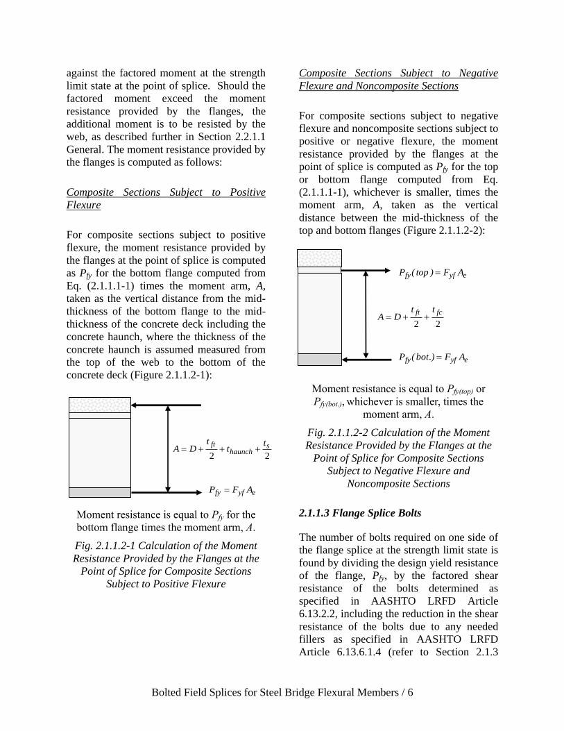
Bolted Field Splices for Steel Bridge Flexural Members / 6
against the factored moment at the strength
limit state at the point of splice. Should the
factored moment exceed the moment
resistance provided by the flanges, the
additional moment is to be resisted by the
web, as described further in Section 2.2.1.1
General. The moment resistance provided by
the flanges is computed as follows:
Composite Sections Subject to Positive
Flexure
For composite sections subject to positive
flexure, the moment resistance provided by
the flanges at the point of splice is computed
as Pfy for the bottom flange computed from
Eq. (2.1.1.1-1) times the moment arm, A,
taken as the vertical distance from the mid-
thickness of the bottom flange to the mid-
thickness of the concrete deck including the
concrete haunch, where the thickness of the
concrete haunch is assumed measured from
the top of the web to the bottom of the
concrete deck (Figure 2.1.1.2-1):
Moment resistance is equal to Pfy for the
bottom flange times the moment arm, A.
Fig. 2.1.1.2-1 Calculation of the Moment
Resistance Provided by the Flanges at the
Point of Splice for Composite Sections
Subject to Positive Flexure
Composite Sections Subject to Negative
Flexure and Noncomposite Sections
For composite sections subject to negative
flexure and noncomposite sections subject to
positive or negative flexure, the moment
resistance provided by the flanges at the
point of splice is computed as Pfy for the top
or bottom flange computed from Eq.
(2.1.1.1-1), whichever is smaller, times the
moment arm, A, taken as the vertical
distance between the mid-thickness of the
top and bottom flanges (Figure 2.1.1.2-2):
Moment resistance is equal to Pfy(top) or
Pfy(bot.), whichever is smaller, times the
moment arm, A.
Fig. 2.1.1.2-2 Calculation of the Moment
Resistance Provided by the Flanges at the
Point of Splice for Composite Sections
Subject to Negative Flexure and
Noncomposite Sections
2.1.1.3 Flange Splice Bolts
The number of bolts required on one side of
the flange splice at the strength limit state is
found by dividing the design yield resistance
of the flange, Pfy, by the factored shear
resistance of the bolts determined as
specified in AASHTO LRFD Article
6.13.2.2, including the reduction in the shear
resistance of the bolts due to any needed
fillers as specified in AASHTO LRFD
Article 6.13.6.1.4 (refer to Section 2.1.3
22
shaunch
ft tt
tDA
eyffy AFP
eyffy AF)top(P
22
fcft ttDA
eyffy AF.)bot(P

Bolted Field Splices for Steel Bridge Flexural Members / 7
Filler Plates (AASHTO LRFD ARTICLE
6.13.6.1.4)). The resulting connections will
develop the full design yield resistance of
each flange (i.e. 100 percent of the design
tension resistance of each flange). The
factored shear resistance of the bolts, Rr, is
calculated as the resistance factor for ASTM
F3125 bolts in shear, ϕs = 0.80, times the
nominal shear resistance of the bolts, Rn,
computed as follows1:
Where threads are excluded from the
shear planes (AASHTO LRFD Eq.
6.13.2.7-1):
subbn NFAR 56.0 (2.1.1.3-1)
Where threads are included in the shear
planes (AASHTO LRFD Eq. 6.13.2.7-
2):
subbn NFAR 45.0 (2.1.1.3-2)
where:
1 In determining the factored shear resistance of the
bolts, if the flange splice-plate thickness closest to
the nut is greater than or equal to 0.5-in. thick, the
nominal shear resistance of the bolts should be
determined assuming the threads are excluded
from the shear planes for bolts less than 1.0 in. in
diameter. For bolts greater than or equal to 1.0 in.
in diameter, the nominal shear resistance of the
bolts should be determined assuming the threads
are excluded from the shear planes if the flange
splice-plate thickness closest to the nut is greater
than 0.75 in. in thickness. Otherwise, the threads
should be assumed included in the shear planes.
The preceding assumes there is one washer under
the nut, and that there is no stick-out beyond the
nut, which represents the worst case for this
determination. Web splice connections will
generally have threads included in the shear plane
due to the relatively thin splice plates in the web
connections.
Ab = area of the bolt corresponding to the
nominal diameter (in.2)
Fub = specified minimum tensile strength
of the bolt specified in AASHTO
LRFD Article 6.4.3.1.1 (ksi)
Ns = number of shear planes per bolt
(Ns = 2 since flange and web splices
are symmetrical double-shear
connections)
As specified in AASHTO LRFD Article
6.13.2.7, for a bolt in a lap splice tension
connection greater than 38.0 in. in length,
the nominal shear resistance, Rn, is taken as
0.83 times the value given by the applicable
equation above. For bolted flange splices,
the 38.0 in. length is measured between the
extreme bolts on only one side of the splice
and is normally not exceeded.
The bearing resistance of the flange splice
bolt holes is also to be checked at the
strength limit state as specified in AASHTO
LRFD Article 6.13.2.9. For standard-size
holes, the factored bearing resistance of the
holes, Rr, is calculated as the resistance
factor for bolts bearing on material, ϕbb =
0.80, times the nominal bearing resistance of
the bolt holes, Rn, computed as follows
(AASHTO LRFD Eqs. 6.13.2.9-1 and
6.13.2.9-2):
With bolts spaced at a clear distance
between holes not less than 2.0d and
with a clear end distance not less than
2.0d:
un dtFR 4.2 (2.1.1.3-3)
If either the clear distance between holes
is less than 2.0d, or the clear end
distance is less than 2.0d:
ucn tFLR 2.1 (2.1.1.3-4)

Bolted Field Splices for Steel Bridge Flexural Members / 8
where:
d = nominal diameter of the bolt (in.)
t = thickness of the connected material
(in.)
Fu = tensile strength of the connected
material specified in AASHTO
LRFD Table 6.4.1-1 (ksi)
Lc = clear distance between holes or
between the hole and the end of the
member in the direction of the
applied bearing force (in.)
The bearing resistance of the connection is
taken as the sum of the smaller of the shear
resistance of the individual bolts and the
bearing resistance of the individual bolt
holes parallel to the line of the design force2.
If the bearing resistance of a bolt hole
exceeds the shear resistance of the bolt, the
bolt resistance is limited to the shear
resistance.
2.1.1.4 Flange Splice Plates
2.1.1.4.1 General
For a typical flange splice with inner and
outer splice plates, an approach is needed to
proportion Pfy to the inner and outer plates.
According to AASHTO LRFD Article
C6.13.6.1.3b, at the strength limit state, Pfy
may be assumed equally divided to the inner
and outer flange splice plates when the areas
2 Assuming the sum of the flange splice-plate
thicknesses exceeds the thickness of the thinner
flange at the point of splice, and the splice plate
areas satisfy the 10 percent rule described in
Section 2.1.1.4.1 General, the bearing resistance
of the connection will be governed by the flange
on either side of the splice with the smaller
product of the thickness and specified minimum
tensile strength, Fu, of the flange. Otherwise, the
bearing resistance of each individual component
should be checked to determine the component
governing the bearing resistance of the
connection.
of the inner and outer plates do not differ by
more than 10 percent. In this case, the shear
resistance of the bolted connection should be
checked for Pfy acting in double shear.
Should the areas of the inner and outer
splice plates differ by more than 10 percent,
the force in each plate should be determined
by multiplying Pfy by the ratio of the area of
the splice plate under consideration to the
total area of the inner and outer plates. In
this case, the shear resistance of the bolted
connection should be checked for the larger
of the calculated splice-plate forces acting
on a single shear plane.
2.1.1.4.2 Splice Plates in Tension
AASHTO LRFD Article 6.13.6.1.3b
specifies that the design force in flange
splice plates subject to tension at the
strength limit state is not to exceed the
factored resistance of the splice plates in
tension specified in AASHTO LRFD Article
6.13.5.2; that is, the splice plates are to be
checked for yielding on the gross section,
fracture on the net section, and for block
shear rupture. Block shear rupture will not
typically control the design of flange splice
plates of typical proportion.
According to AASHTO LRFD Article
6.13.5.2, the factored yield resistance of a
connected element in tension, Rr, is
computed from AASHTO LRFD Equation
6.8.2.1-1 as follows:
gyyr AFR (2.1.1.4.2-1)
where:
y = resistance factor for yielding of
tension members as specified in
AASHTO LRFD Article 6.5.4.2 =
0.95

Bolted Field Splices for Steel Bridge Flexural Members / 9
Fy = specified minimum yield strength of
the connected element (ksi)
Ag = gross cross-sectional area of the
connected element (in.2)
According to AASHTO LRFD Article
6.13.5.2, the factored net section fracture
resistance of a connected element in tension,
Rr, is computed from AASHTO LRFD
Equation 6.8.2.1-2 as follows:
URAFR pnuur (2.1.1.4.2-2)
where:
u = resistance factor for fracture of
tension members as specified in
AASHTO LRFD Article 6.5.4.2 =
0.80
Fu = tensile strength of the connected
element specified in AASHTO
LRFD Table 6.4.1-1 (ksi)
An = net cross-sectional area of the
connected element determined as
specified in AASHTO LRFD Article
6.8.3 (in.2)
Rp = reduction factor for holes taken equal
to 0.90 for bolt holes punched full
size, and 1.0 for bolt holes drilled
full size or subpunched and reamed
to size (use 1.0 for splice plates since
the holes in field splices are not
allowed to be punched full size)
U = reduction factor to account for shear
lag (use 1.0 for splice plates since all
elements are connected)
Furthermore, according to AASHTO LRFD
Article 6.13.5.2, for splice plates subject to
tension, the design net area of the splice
plates, An, must not exceed 0.85Ag, where Ag
is the gross area of the splice plates. Should
An equal or exceed 0.85Ag, then 0.85Ag is
substituted for An in Eq. 2.1.1.4.2-2;
otherwise, An is used.
The factored block shear rupture resistance,
Rr, is determined according to the provisions
of AASHTO LRFD Article 6.13.4 as
follows (AASHTO LRFD Eq. 6.13.4-1):
tnubsvnupbsr AFUAFRR 58.0
tnubsvgypbs AFUAFR 58.0
(2.1.1.4.2-3)
where:
bs = resistance factor for block shear
rupture as specified in AASHTO
LRFD Article 6.5.4.2 = 0.80
Avg = gross area along the plane resisting
shear stress (in.2)
Avn = net area along the plane resisting
shear stress (in.2)
Atn = net area along the plane resisting
tension stress (in.2)
Ubs = reduction factor for block shear
rupture resistance taken equal to 0.50
when the tension stress is non-
uniform and 1.0 when the tension
stress is uniform (use 1.0 for splice
plates)
2.1.1.4.3 Splice Plates in Compression
The factored yield resistance of the splice
plates in compression is the same as the
factored yield resistance of the splice plates
in tension given by Eq. (2.1.1.4.2-1), and
therefore, need not be checked. Buckling of
the splice plates in compression is not a
concern since the unsupported length of the
plates is limited by the maximum bolt
spacing and end distance requirements.
2.1.2 Slip Resistance Check
The moment resistance provided by the
nominal slip resistance of the flange splice
bolts is checked against the factored moment

Bolted Field Splices for Steel Bridge Flexural Members / 10
for checking slip. The factored moments for
checking slip are taken as the moment at the
point of splice under Load Combination
Service II, as specified in AASHTO LRFD
Table 3.4.1-1, and also the factored moment
at the point of splice due to the deck casting
sequence, as specified in AASHTO LRFD
Article 3.4.2.1.
The nominal slip resistance of the bolts, Rn,
is computed as follows (AASHTO LRFD
Eq. 6.13.2.8-1):
tsshn PNKKR (2.1.2-1)
where:
Ns = number of slip planes per bolt
Pt = minimum required bolt tension
specified in AASHTO LRFD Table
6.13.2.8-1 (kips)
Kh = hole size factor specified in
AASHTO LRFD Table 6.13.2.8-2
Ks = surface condition factor specified in
AASHTO LRFD 6.13.2.8-3
As discussed in AASHTO LRFD Article
C6.13.6.1.3b, when checking the slip
resistance of the bolts for a typical flange
splice with inner and outer splice plates, the
flange slip force is assumed divided equally
to the two slip planes regardless of the ratio
of the splice plate areas. Unless slip occurs
on both planes, slip of the connection cannot
occur. Therefore, in this case, the slip
resistance of the bolted connection should
always be computed assuming two slip
planes (i.e. Ns = 2 in Eq. (2.1.2-1)).
The moment resistance provided by the
nominal slip resistance of the flange splice
bolts is computed as described in Section
2.1.1.2 Moment Resistance Check,
substituting the nominal slip resistance of
the bolts for Pfy, and checked against the
corresponding factored moment for
checking slip defined above. For checking
slip due to the factored deck casting
moment, the moment resistance of the
noncomposite section is used. Should the
flange bolts not be sufficient to resist the
factored moment for checking slip at the
point of splice, the additional moment is to
be resisted by the web, as described in
Section 2.2.2 Slip Resistance Check
Should the web bolts not be sufficient to
resist the additional moment, only then
should consideration be given to adding
additional bolts to the flange splices.
A check of the flexural stresses in the flange
splice plates under Load Combination
Service II to control permanent
deformations is not required since the
combined areas of the flange splice plates
must equal or exceed the areas of the smaller
flanges to which they are attached.
Except for the box sections mentioned
previously in Section 2.1.1.1 General, the St.
Venant torsional shear in the bottom flange
is to be considered in the design of the
bottom flange splice when checking the
bolts for slip. Rather than using the vector
sum in this case, the shear is conservatively
subtracted from the nominal slip resistance
of the flange splice bolts prior to computing
the moment resistance. St. Venant torsional
shears and longitudinal warping stresses due
to cross-section distortion are typically
neglected in top flanges of tub sections once
the flanges are continuously braced.
Longitudinal warping stresses due to cross-
section distortion are typically relatively
small in the bottom flange at the service
limit state and for constructibility and may
be neglected when checking bottom flange
splices for slip.
For straight girders and for horizontally
curved girders, the effects of flange lateral

Bolted Field Splices for Steel Bridge Flexural Members / 11
bending need not be considered in checking
the bolted connections of the flange splices
for slip. Flange lateral bending will increase
the flange slip force on one side of the splice
and decrease the slip force on the other side
of the splice; slip cannot occur unless it
occurs on both sides of the splice.
2.1.3 Filler Plates (AASHTO LRFD
Article 6.13.6.1.4)
Filler plates are typically used on bolted
flange splices of flexural members (and
sometimes on web splices) when the
thicknesses of the adjoining plates at the
point of splice are different (Figure 1-1).
At bolted flange splices, it is often
advantageous to transition one or more of
the flange thicknesses down adjacent to the
point of splice, if possible, so as to reduce
the required size of the filler plate, or
possibly change the width of the flanges at
the splice and keep the thicknesses constant
in order to eliminate the need for a filler
plate altogether.
Fillers thicker than ¼ in. must be secured by
additional bolts to ensure that the fillers are
an integral part of the connection; that is, to
ensure that the shear planes are well-defined
and that no reduction in the factored shear
resistance of the bolts results.
AASHTO LRFD Article 6.13.6.1.4 provides
two choices for developing fillers ¼ in. or
more in thickness in girder flange splices.
The choices are to either: 1) extend the
fillers beyond the splice plate with the filler
extension secured by enough additional
bolts to distribute the total stress uniformly
over the combined section of the member or
filler; or 2) in lieu of extending and
developing the fillers, reduce the factored
shear resistance of the bolts by the following
factor (AASHTO LRFD Eq. 6.13.6.1.4-1):
21
1R (2.1.3-1)
where:
= Af/Ap
Af = sum of the area of the fillers on the
top and bottom of the connected
plate (in.2)
Ap = smaller of either the connected plate
area on the side of the connection
with the filler or the sum of the
splice plate areas on the top and
bottom of the connected plate (in.2)
The reduction factor, R, accounts for the
reduction in the nominal shear resistance of
the bolts due to bending in the bolts and will
likely result in having to provide additional
bolts in the connection to develop the
filler(s). Note that the reduction factor is
only to be applied on the side of the splice
with the filler(s). For practical reasons,
consideration should be given to using the
same number of bolts on either side of the
splice. Note that fillers ¼ in. or more in
thickness are not to consist of more than two
plates, unless approved by the Engineer.
Additional requirements regarding the
specified minimum yield strength of fillers
are given in AASHTO LRFD Article
6.13.6.1.4.
The slip resistance of the connection is not
affected by the filler. Therefore, as specified
in AASHTO LRFD Article 6.13.6.1.4, for
slip-critical connections, the nominal slip
resistance of the bolts is not to be adjusted
for the effect of the fillers.
Bolted Field Splices for Steel Bridge Flexural Members / 12
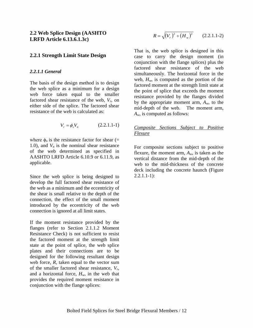
2.2 Web Splice Design (AASHTO
LRFD Article 6.13.6.1.3c)
2.2.1 Strength Limit State Design
2.2.1.1 General
The basis of the design method is to design
the web splice as a minimum for a design
web force taken equal to the smaller
factored shear resistance of the web, Vr, on
either side of the splice. The factored shear
resistance of the web is calculated as:
nvr VV (2.2.1.1-1)
where ϕv is the resistance factor for shear (=
1.0), and Vn is the nominal shear resistance
of the web determined as specified in
AASHTO LRFD Article 6.10.9 or 6.11.9, as
applicable.
Since the web splice is being designed to
develop the full factored shear resistance of
the web as a minimum and the eccentricity of
the shear is small relative to the depth of the
connection, the effect of the small moment
introduced by the eccentricity of the web
connection is ignored at all limit states.
If the moment resistance provided by the
flanges (refer to Section 2.1.1.2 Moment
Resistance Check) is not sufficient to resist
the factored moment at the strength limit
state at the point of splice, the web splice
plates and their connections are to be
designed for the following resultant design
web force, R, taken equal to the vector sum
of the smaller factored shear resistance, Vr,
and a horizontal force, Hw, in the web that
provides the required moment resistance in
conjunction with the flange splices:
22
wr HVR (2.2.1.1-2)
That is, the web splice is designed in this
case to carry the design moment (in
conjunction with the flange splices) plus the
factored shear resistance of the web
simultaneously. The horizontal force in the
web, Hw, is computed as the portion of the
factored moment at the strength limit state at
the point of splice that exceeds the moment
resistance provided by the flanges divided
by the appropriate moment arm, Aw, to the
mid-depth of the web. The moment arm,
Aw, is computed as follows:
Composite Sections Subject to Positive
Flexure
For composite sections subject to positive
flexure, the moment arm, Aw, is taken as the
vertical distance from the mid-depth of the
web to the mid-thickness of the concrete
deck including the concrete haunch (Figure
2.2.1.1-1):

Bolted Field Splices for Steel Bridge Flexural Members / 13
Aw = D2 + thaunch +
Hw
ts
2
ww AHMomentWeb
ww
A
MomentWebH
Aw is measured from the mid-depth of the web to
the mid-thickness of the deck.
Fig. 2.2.1.1-1 Calculation of the Moment
Arm, Aw, for Composite Sections Subject to
Positive Flexure
Composite Sections Subject to Negative
Flexure and Noncomposite Sections
For composite sections subject to negative
flexure and noncomposite sections subject to
positive or negative flexure, the moment
arm, Aw, is taken as one-quarter of the web
depth (Figure 2.2.1.1-2):
D2
D2
D2
Hw
2
Hw
2
22
DHMomentWeb
w
4/D
MomentWebHw
Fig. 2.2.1.1-2 Calculation of the Moment
Arm, Aw, for Composite Sections Subject to
Negative Flexure and Noncomposite
Sections
The required moment resistance in the web
for the case shown in Figure 2.2.1.1-1 is
provided by a horizontal tensile force, Hw,
assumed acting at the mid-depth of the web
that is equilibrated by an equal and opposite
horizontal compressive force in the concrete
deck. The required moment resistance in the
web for the case of composite sections
subject to negative flexure and noncomposite
sections is calculated as shown in Figure
2.2.1.1-2. The resisting web moment is
provided by two equal and opposite
horizontal tensile and compressive forces,
Hw/2, assumed acting at a distance D/4 above
and below the mid-height of the web. In
each case, there is no net horizontal force
acting on the section.
Because the resultant web force is assumed
divided equally to all of the bolts, the
traditional vector analysis is not applied.

Bolted Field Splices for Steel Bridge Flexural Members / 14
Lastly, for box sections, the effect of the
additional St. Venant torsional shear in the
web may be ignored in the design of the web
splice at the strength limit state since the web
splice is being designed as a minimum for the
full factored shear resistance of the web.
2.2.1.2 Web Splice Bolts
The number of bolts required on one side of
the web splice at the strength limit state is
found by dividing the computed design web
force by the factored shear resistance of the
bolts. The factored shear resistance of the
bolts, Rr, is calculated as the resistance
factor for ASTM F3125 bolts in shear, ϕs =
0.80, times the nominal shear resistance of
the bolts, Rn, calculated assuming the
threads are included in the shear planes for
most common web splices since the web
splice-plate thicknesses are normally less
than or equal to ½ in.
Note that the greater than 38.0 in. length
reduction for the shear resistance of the bolts
only applies to lap-splice tension
connections (AASHTO LRFD Article
6.13.2.7), and therefore should not be
applied in the design of the web splice.
As a minimum, two vertical rows of bolts
spaced at the maximum spacing for sealing
bolts specified in AASHTO LRFD Article
6.13.2.6.2 should be provided, with a closer
spacing and/or additional rows provided only
as needed.
The bearing resistance of the web splice bolt
holes is also to be checked at the strength
limit state as specified in AASHTO LRFD
Article 6.13.2.9. For standard holes, the
factored bearing resistance of the holes, Rr,
is calculated as the resistance factor for bolts
bearing on material, ϕbb = 0.80, times the
nominal bearing resistance of the bolt holes,
Rn, computed from Eq. (2.1.1.3-3) or Eq.
(2.1.1.3-4), as applicable. The bearing
resistance may be calculated as the sum of
the smaller of the shear resistance of the
individual bolts and the bearing resistance of
the individual bolt holes parallel to the line
of the design force. If the bearing resistance
of a bolt hole exceeds the shear resistance of
the bolt, the bolt resistance is limited to the
shear resistance.
When a moment contribution from the web
is required, the resultant forces causing
bearing on the web bolt holes are inclined
(Figure 2.2.1.2-1). The bearing resistance of
each bolt hole in the web can conservatively
be calculated in this case using the clear
edge distance, as shown on the left-hand
side of Figure 2.2.1.2-1. This calculation is
conservative since the resultant forces act in
the direction of inclined distances that are
larger than the clear edge distance. This
calculation is also likely to be a conservative
calculation for the bolt holes in the adjacent
rows. Should the bearing resistance be
exceeded, it is recommended that the clear
edge distance be increased slightly in lieu of
increasing the number of bolts or thickening
the web. Other options would be to calculate
the bearing resistance based on the inclined
distances, or to resolve the resultant forces
in the direction parallel to the clear edge
distance, or to refine the calculation for the
bolt holes in the adjacent rows. In cases
where the bearing resistance is controlled by
the web splice plates, the smaller of the clear
edge or end distance on the splice plates can
conservatively be used to compute the
bearing resistances of each hole, as shown
on the right-hand side of Figure 2.2.1.2-1.

Bolted Field Splices for Steel Bridge Flexural Members / 15
Web Splice Plates
Fig. 2.2.1.2-1 Computing the Bearing
Resistance of the Web Splice Bolt Holes for
an Inclined Resultant Design Web Force
2.2.1.3 Web Splice Plates
Webs are to be spliced symmetrically by
plates on each side. The splice plates are to
extend as near as practical for the full depth
between flanges without impinging on bolt
assembly clearances. Required bolt
assembly clearances are given in Tables 7-
15 and 7-16 of AISC (2011), as applicable.
For bolted web splices with thickness
differences of 1/16 in. or less, filler plates
should not be provided. A minimum gap of
½ in. between the girder sections at the
splice should be provided to provide
drainage and allow for fit-up.
The factored shear resistance of the web at
the strength limit state, Vr, is not to exceed
the lesser of the factored shear resistances of
the web splice plates determined as specified
in AASHTO LRFD Article 6.13.5.3.
AASHTO LRFD Article 6.13.5.3 specifies
that the factored shear resistance, Rr, of a
connected element is to be taken as the
smaller value based on shear yielding or
shear rupture.
For shear yielding, the factored shear
resistance of the splice plates, Rr, is
conservatively based on the shear yield
stress (i.e. 3yF = 0.58Fy) as follows
(AASHTO LRFD Eq. 6.13.5.3-1):
vgyvr AFR 58.0 (2.2.1.3-1)
where:
v = resistance factor for shear specified
in AASHTO LRFD Article 6.5.4.2 =
1.0
Avg = gross area of the splice plates subject
to shear (in.2)
Fy = specified minimum yield strength of
the splice plates (ksi)
For shear rupture, the factored shear
resistance of the splice plates, Rr, is taken as
follows (AASHTO LRFD Eq. 6.13.5.3-2):
vnupvur AFRR 58.0 (2.2.1.3-2)
where:
vu = resistance factor for shear rupture of
connected elements specified in
AASHTO LRFD Article 6.5.4.2 =
0.80
Avn = net area of the splice plates subject to
shear (in.2)
Fu = tensile strength of the splice plates
specified in AASHTO LRFD Table
6.4.1-1 (ksi)
Rp = reduction factor for holes taken equal
to 0.90 for bolt holes punched full
size and 1.0 for bolt holes drilled full
size or subpunched and reamed to
size (use 1.0 for splice plates since
the holes in field splices are not
allowed to be punched full size)
The factored shear resistance of the web at
the strength limit state, Vr, is also not to
exceed the factored block shear rupture
resistance of the web splice plates
determined as specified in AASHTO LRFD
Article 6.13.4 (see Eq. (2.1.1.4.2-3)).
2.2.2 Slip Resistance Check
As a minimum, AASHTO LRFD Article
6.13.6.1.3c specifies that bolted connections

Bolted Field Splices for Steel Bridge Flexural Members / 16
for web splices be checked for slip under a
web slip force taken equal to the factored
shear in the web at the point of splice. The
factored shear for checking slip is taken as
the shear in the web at the point of splice
under Load Combination Service II, as
specified in AASHTO LRFD Table 3.4.1-1,
or the factored shear at the point of splice
due to the deck casting sequence, as
specified in AASHTO LRFD Article
3.4.2.1, whichever governs.
Should the flange bolts not be sufficient to
resist the factored moment for checking slip
at the point of splice (see Section 2.1.2 Slip
Resistance Check), the web splice bolts
should instead be checked for slip under a
web slip force taken equal to the vector sum
of the factored shear and a horizontal force,
Hw, located in the web that provides the
necessary slip resistance in conjunction with
the flange splices. The horizontal force in
the web, Hw, is computed as the portion of
the factored moment for checking slip at the
point of splice that exceeds the moment
resistance provided by the nominal slip
resistance of the flange splice bolts divided
by the appropriate moment arm, Aw. The
moment arm, Aw, is computed as described
in Section 2.2.1.1 General.
The computed slip force is then divided by
the nominal slip resistance of the bolts,
determined as specified in AASHTO LRFD
Article 6.13.2.8, to determine the number of
web splice bolts required on one side of the
splice to resist slip. The nominal slip
resistance of the bolts, Rn, is computed from
Eq. (2.1.2-1).
Except for the box sections mentioned
previously in Section 2.1.1.1 General, the
shear for checking slip is taken as the sum of
the flexural and St. Venant torsional shears
in the web subject to additive shears since
slip is a serviceability criterion. For boxes
with inclined webs, the factored shear is
taken as the component of the factored
vertical shear in the plane of the web
(AASHTO LRFD Eq. 6.11.9-1).
Bolted Field Splices for Steel Bridge Flexural Members / 17
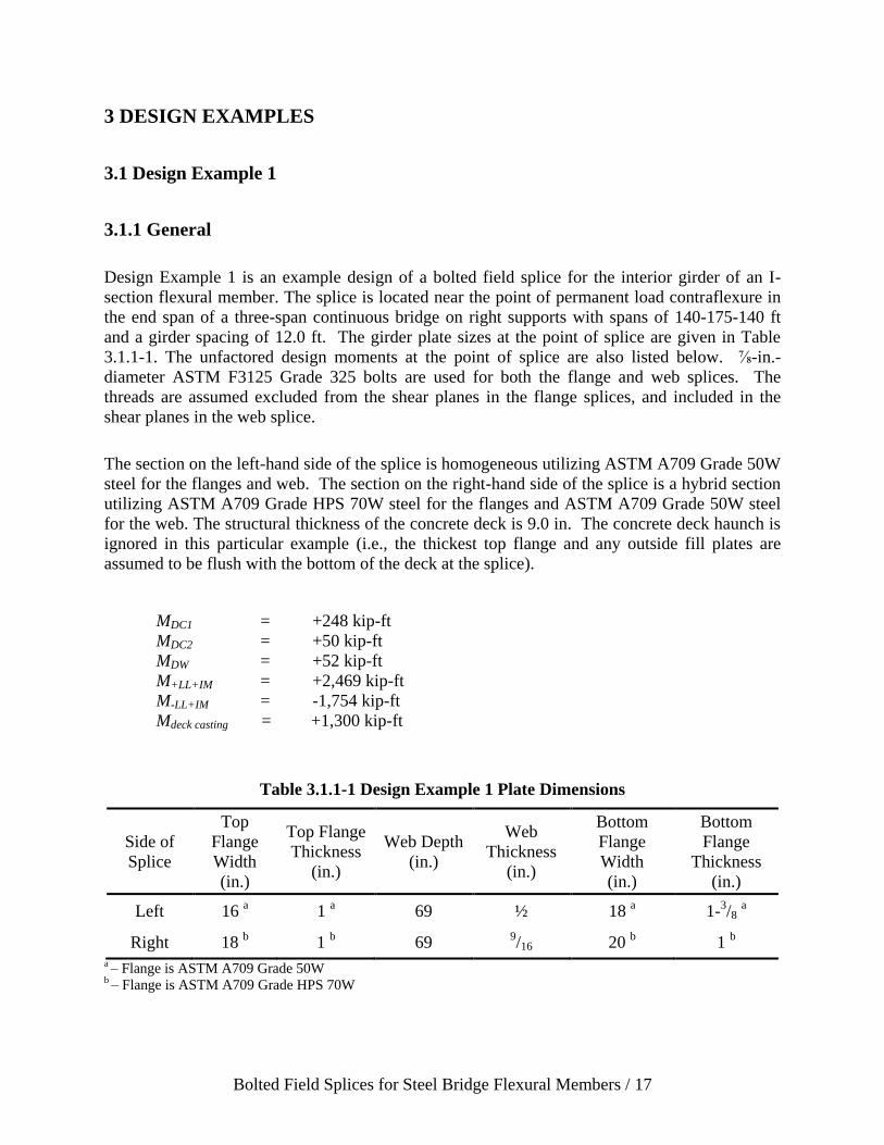
3 DESIGN EXAMPLES
3.1 Design Example 1
3.1.1 General
Design Example 1 is an example design of a bolted field splice for the interior girder of an I-
section flexural member. The splice is located near the point of permanent load contraflexure in
the end span of a three-span continuous bridge on right supports with spans of 140-175-140 ft
and a girder spacing of 12.0 ft. The girder plate sizes at the point of splice are given in Table
3.1.1-1. The unfactored design moments at the point of splice are also listed below. ⅞-in.-
diameter ASTM F3125 Grade 325 bolts are used for both the flange and web splices. The
threads are assumed excluded from the shear planes in the flange splices, and included in the
shear planes in the web splice.
The section on the left-hand side of the splice is homogeneous utilizing ASTM A709 Grade 50W
steel for the flanges and web. The section on the right-hand side of the splice is a hybrid section
utilizing ASTM A709 Grade HPS 70W steel for the flanges and ASTM A709 Grade 50W steel
for the web. The structural thickness of the concrete deck is 9.0 in. The concrete deck haunch is
ignored in this particular example (i.e., the thickest top flange and any outside fill plates are
assumed to be flush with the bottom of the deck at the splice).
MDC1 = +248 kip-ft
MDC2 = +50 kip-ft
MDW = +52 kip-ft
M+LL+IM = +2,469 kip-ft
M-LL+IM = -1,754 kip-ft
Mdeck casting = +1,300 kip-ft
Table 3.1.1-1 Design Example 1 Plate Dimensions
Side of
Splice
Top
Flange
Width
(in.)
Top Flange
Thickness
(in.)
Web Depth
(in.)
Web
Thickness
(in.)
Bottom
Flange
Width
(in.)
Bottom
Flange
Thickness
(in.)
Left 16 a 1
a 69 ½ 18
a 1-
3/8
a
Right 18 b
1 b
69 9/16 20
b 1
b
a – Flange is ASTM A709 Grade 50W b – Flange is ASTM A709 Grade HPS 70W

Bolted Field Splices for Steel Bridge Flexural Members / 18
The factored Strength I design moments at the point of splice are computed as follows:
Positive Moment = 1.25(248+50) + 1.5(52) + 1.75(2,469) = +4,771 kip-ft
Negative Moment = 0.9(248+50) + 0.65(52) + 1.75(-1,754) = -2,768 kip-ft
3.1.2 Flange Splice Design
3.1.2.1 Strength Limit State Design
3.1.2.1.1 Bolts
Top Flange
The left side of the splice has the smaller design yield resistance (i.e., the top flange on the left
side has a smaller area and lower yield strength).
Assuming 4 rows of bolts across the width of the flange (Eq. (2.1.1.1-3)
Ae = 1.18(1)[16 - 4(15
/16)] = 14.4 in.2 < 1(16) in.
2 = 16.0 in.
2
Pfy = 50(14.4) = 720 kips
The factored shear resistance of the bolts in double shear (Ns = 2) is computed as follows:
Bolts with threads excluded from the shear plane (Eq. (2.1.1.3-1)):
kips6.64)2)(120)(601.0)(56.0(80.056.0*80.0 subbnsr NFARR
Number of Bolts Required: N = 720/64.6 = 11.1
Use 4 rows with 3 bolts per row = 12 bolts on each side of the splice.
Bottom Flange
Check which side of the splice has the flange with the smaller design yield resistance:
Left Side
Ae = 1.18(1.375)[18 - 4(15
/16)] = 23.1 in.2 < 1.375(18) in.
2 = 24.75 in.
2
Pfy = 50(23.1) = 1,152 kips

Bolted Field Splices for Steel Bridge Flexural Members / 19
Right Side
Ae = 1.02(1)[20 - 4(15
/16)] = 16.6 in.2 < 1.0(20) in.
2
Pfy = 70(16.6) = 1,162 kips > 1,152 kips; therefore, the left side controls
Pfy = 1,152 kips
Reduction in bolt factored shear resistance due to filler (Eq. (2.1.3-1)):
79.0
1
)375.0(21
1
375.01
R
Note that the splice plate, filler plate, and flange widths will be equal in the splice.
Consequently, the area ratios are only a function of the thickness of the flange and fillers.
Number of Bolts Required (threads excluded from the shear planes): N = 1,152/(0.79(64.6)) =
22.6
Use 4 rows with 6 bolts per row = 24 bolts on each side of the splice.
3.1.2.1.2 Moment Resistance
Positive Moment (Figure 2.1.1.2-1; thaunch = 0)
Use Pfy for the bottom flange = 1,152 kips.
Flange Moment Arm: A = D + tft/2 + tfc + ts/2 = 69 + 1.375/2 + 1 + 9/2 = 75.2 in.
Mflange = 1,152 x (75.2/12) = 7,218 kip-ft > 4,771 kip-ft ok
Negative Moment (Figure 2.1.1.2-2)
Use the smaller value of Pfy for the top and bottom flanges. In this case, the top flange has the
smaller value of Pfy = 720 kips.
Flange Moment Arm: A = D + (tft + tfc)/2 = 69 + (1.375+1)/2 = 70.2 in.
Mflange = 720 x (70.2/12) = 4,211 kip-ft >|-2,768 kip-ft| ok
Therefore, the flanges have adequate capacity to resist the Strength I moment requirements at the
splice. No moment contribution from the web is required.

Bolted Field Splices for Steel Bridge Flexural Members / 20
3.1.2.1.3 Splice Plates
The width of the outside splice plate should be at least as wide as the width of the narrowest
flange at the splice. The width of the inside splice plates should be such that the plates clear the
flange-to-web weld on each side of the web by a minimum of ⅛ in. Therefore, for the bottom-
flange splice, try a ¾ in. x 18 in. outside splice plate and two ⅞ in. x 8 in. inside splice plates.
Include a ⅜ in. x 18 in. filler plate on the outside. All plates are ASTM A709 Grade 50W steel.
At the strength limit state, Pfy may be assumed equally divided to the inner and outer flange
splice plates when the areas of the inner and outer plates do not differ by more than 10 percent.
In this case, the areas of the inner and outer plates are within approximately 4 percent.
Therefore, Pfy is equally divided to the inner and outer plates and the shear resistance of the
bolted connection is checked above for Pfy acting in double shear.
Check the factored yield resistance of the splice plates in tension (Eq. (2.1.1.4.2-1)):
Outside splice plate:
okkips5762/152,1kips641)75.0)(0.18)(50(95.0 rR
Inside splice plates:
okkips5762/152,1kips665)875.0)(0.8)(2)(50(95.0 rR
Check the net section fracture resistance of the splice plates in tension (Eq. (2.1.1.4.2-2)). As
specified in AASHTO LRFD Article 6.8.3, for design calculations, the width of standard-size
bolt holes is taken as the nominal diameter of the holes, or 15
/16 in. for a ⅞-in.-diameter bolt.
According to AASHTO LRFD Article 6.13.5.2, for splice plates subject to tension, the design
net area, An, must not exceed 0.85Ag.
Outside plate:
okin.7.10)75.0()9375.0(40.18in.5.11)75.0)(0.18(85.0 22 nA
Inside plates:
okin.7.10)875.0()9375.0(4)0.8(2in.9.11)875.0)(0.8)(2(85.0 22 nA
Therefore, use the net area to check the net section fracture resistance of the splice plates.
Outside plate:
okkips5762/152,1kips599)0.1)(0.1)(75.0)](9375.0(40.18)[70(80.0 rR

Bolted Field Splices for Steel Bridge Flexural Members / 21
Inside plates:
okkips5762/152,1kips600)0.1)(0.1)(875.0)](9375.0(4)0.8(2)[70(80.0 rR
In order to check the block shear rupture resistance of the splice plates and the flange (and later
on the factored bearing resistance of the bolt holes in Section 3.1.2.1.4 Bearing Resistance
Check), the bolt spacings and bolt edge and end distances must first be established and checked.
Refer to the bolt pattern shown in Figure 3.1.2.1.3-1.
5 SPACES @ 3" = 1'-3"
1 1/2" (TYP.)
2" (TYP.)
4" (TYP.)
6"
CL FIELD SPLICE
OUTSIDE SPLICE
PLATE 34" x 18"
Fig. 3.1.2.1.3-1 Outside Bottom Flange Splice Plate – Plan View
As specified in AASHTO LRFD Article 6.13.2.6.1, the minimum spacing between centers of
bolts in standard holes is not to be less than 3.0d, where d is the diameter of the bolt. For ⅞-in.-
diameter bolts:
.in3.0use.in63.2)875.0(33min ds
Since the length between the extreme bolts (on one side of the splice) measured parallel to the
line of action of the force is less than 38.0 in., no reduction in the factored shear resistance of the
bolts is required, as originally assumed.
As specified in AASHTO LRFD Article 6.13.2.6.2, to seal against the penetration of moisture in
joints, the spacing, s, of a single line of bolts adjacent to a free edge of an outside plate or shape
(when the bolts are not staggered) must satisfy the following requirement:
in.0.70.40.4 ts
where t is the thickness of the thinner outside plate or shape. First, check for sealing along the
edges of the outer splice plate (the thinner plate) parallel to the direction of the applied force.
The bolt lines closest to the edges of the flanges are assumed to be 1-½ in. from the edges of the
Bolted Field Splices for Steel Bridge Flexural Members / 22
flanges. A ¾ in. gap is assumed between the girder flanges at the splice to allow the splice to
provide drainage and allow for fit-up:
okin.75.3.in00.7)75.0(0.40.4max s
Check for sealing along the free edge at the end of the splice plate:
okin.0.6.in00.7)75.0(0.40.4max s
Note that the maximum pitch requirements for stitch bolts specified in AASHTO LRFD Article
6.13.2.6.3 apply only to the connection of plates in mechanically fastened built-up members and
are not to be applied here in the design of the splice.
The edge distance of bolts is defined as the distance perpendicular to the line of force between
the center of a hole and the edge of the component. In this example, the edge distance of 2.0 in.
satisfies the minimum edge distance requirement of 1-⅛ in. specified for ⅞-in.-diameter bolts in
AASHTO LRFD Table 6.13.2.6.6-1. This distance also satisfies the maximum edge distance
requirement of 8.0t (not to exceed 5.0 in.) = 8.0(0.75) = 6.0 in. specified in AASHTO LRFD
Article 6.13.2.6.6.
The end distance of bolts is defined as the distance along the line of force between the center of a
hole and the end of the component. In this example, the end distance of 1-½ in. satisfies the
minimum end distance requirement of 1-⅛ in. specified for ⅞-in.-diameter bolts. The maximum
end distance requirement of 6.0 in. is also obviously satisfied. Although not specifically
required, note that the distance from the corner bolts to the corner of the splice plate, equal to
.in5.2)0.2(5.1 22 , also satisfies the maximum end distance requirement. If desired, the
corners of the plate can be clipped to meet this requirement. Fabricators generally prefer that the
end distance on the all girder flanges at the point of splice be increased a minimum of ¼ in. from
the design value to allow for girder trim.
Check the block shear rupture resistance of the splice plates in tension (Eq. (2.1.1.4.2-3).
Assume the potential block shear failure planes on the outside and inside splice plates shown in
Fig. 3.1.2.1.3-2.

Bolted Field Splices for Steel Bridge Flexural Members / 23
Fig. 3.1.2.1.3-2 Bottom Flange Splice – Assumed Block Shear Failure Planes in the Splice Plates
Check the outside splice plate. Atn is the net area along the place resisting the tensile stress.
2in.89.6)75.0()9375.0(5.10.20.42 tnA
Avn is the net area along the place resisting the shear stress.
2in.01.17)75.0()9375.0(5.55.1)0.3(52 vnA
Avg is the gross area along the plane resisting the shear stress.
2in.75.24)75.0(5.1)0.3(52 vgA
Therefore:
okkips5762
152,1kips938
kips960)89.6)(70(0.175.24)50(58.0)0.1(80.0kips938)89.6)(70(0.1)01.17)(70(58.0)0.1(80.0
r
r
R
R

Bolted Field Splices for Steel Bridge Flexural Members / 24
Check the inside splice plates.
2.in04.8)875.0()9375.0(5.10.20.42 tnA
2in.85.19)875.0()9375.0(5.55.1)0.3(52 vnA
2in.87.28)875.0(5.1)0.3(52 vgA
okkips5762
152,1kips095,1
kips120,1)04.8)(70(0.187.28)50(58.0)0.1(80.0kips095,1)04.8)(70(0.1)85.19)(70(58.0)0.1(80.0
r
r
R
R
Check the block shear rupture resistance in tension of the critical girder bottom flange at the
splice. Since the areas and yield strengths of the flanges on each side of the splice differ, both
sides need to be checked. Only the calculations for the flange on the right-hand side of the
splice, which is determined to be the critical flange for this check, are shown below. Two
potential failure modes are investigated for the flange as shown in Figure 3.1.2.1.3-3.
5 SPACES @ 3" = 1'-3"1 1/2"
3"
4"
6"
CL FIELD SPLICE
BOTTOM FLANGE
PLATE 1" x 20"
3"
4"
BLOCK SHEAR
FAILURE PLANE
BLOCK SHEAR
FAILURE PLANE
5 SPACES @ 3" = 1'-3"1 1/2"
3"
4"
6"
BOTTOM FLANGE
PLATE 1" x 20"
3"
4"
BLOCK SHEAR
FAILURE PLANE
BLOCK SHEAR
FAILURE PLANE
Failure Mode 1
Failure Mode 2
Fig. 3.1.2.1.3-3 Bottom Flange Splice – Assumed Block Shear Failure Planes in the Flange on
the Right-Hand Side of the Splice

Bolted Field Splices for Steel Bridge Flexural Members / 25
For Failure Mode 1:
2in13.6)0.1(9375.00.42 tnA
2in37.45)0.1()9375.0(5.55.1)0.3(54 vnA
2in00.66)0.1(5.1)0.3(54 vgA
okkips152,1kips206,2
kip560,2)13.6)(85(0.100.66)70(58.0)0.1(80.0kips206,2)13.6)(85(0.1)37.45)(85(58.0)0.1(80.0
r
r
R
sR
For Failure Mode 2:
2in.19.11)0.1()9375.0(5.10.30.42 tnA
2in.69.22)0.1()9375.0(5.55.1)0.3(52 vnA
2in.00.33)0.1(5.1)0.3(52 vgA
okkips152,1kips656,1
kips833,1)19.11)(85(0.100.33)70(58.0)0.1(80.0kips656,1)19.11)(85(0.1)69.22)(85(58.0)0.1(80.0
r
r
R
R
Separate computations indicate that AASHTO LRFD Eq. 6.10.1.8-1 is also satisfied for both
flanges of the girder at the splice at the strength limit state.
Since the combined area of the inside and outside flange splice plates is greater than the area of
the smaller bottom flange at the point of splice, fatigue of the base metal of the bottom flange
splice plates adjacent to the slip-critical bolted connections does not need to be checked.
Similarly, the flexural stresses in the splice plates at the service limit state under the Service II
load combination need not be checked.
Calculations similar to the above show that a ⅝ in. x 16 in. outside splice plate with two 11
/16 in.
x 7 in. inside splice plates are sufficient to resist the design yield resistance of the top flange, Pfy
= 720 kips. A filler plate is not required. All plates are again ASTM A709 Grade 50W steel.

Bolted Field Splices for Steel Bridge Flexural Members / 26
3.1.2.1.4 Bearing Resistance Check
The bearing resistance of the connection at the strength limit state is taken as the sum of the
smaller of the shear resistance of the individual bolts and the bearing resistance of the individual
bolt holes parallel to the line of the design force.
The bearing resistance of connected material in the bottom flange splice will be checked herein.
The sum of the inner and outer splice plate thicknesses exceeds the thickness of the thinner
flange at the point of splice, and the splice plate areas satisfy the 10 percent rule described in
Section 2.1.1.4.1 General. Therefore, check which flange on either side of the splice has the
smaller product of the thickness times the specified minimum tensile strength, Fu, of the flange to
determine which flange controls the bearing resistance of the connection.
Bottom Flange Left Side: .in/kips3.96)70)(375.1(
Bottom Flange Right Side: )governs(.in/kips0.85)85)(0.1(
For standard-size holes, the nominal bearing resistance, Rn, parallel to the applied bearing force
is given by Eq. (2.1.1.3-3) or Eq. (2.1.1.3-4), as applicable.
For the four bolt holes adjacent to the end of the flange, the end distance is 1-½ in. Therefore,
the clear distance, Lc, between the edge of the hole and the end of the flange is:
in.75.1)875.0(0.20.2.in03.12
9375.05.1 dLc
Therefore, use Eq. (2.1.1.3-4):
kips420)85)(0.1)(03.1(2.14)2.1(4 ucn tFLR
Since:
nbbr RR
Rr = 0.80(420) = 336 kips
The total factored shear resistance of the bolts in the four holes adjacent to the end of the flange,
acting in double shear and accounting for the presence of the filler, is 4(0.79)(64.6) = 204 kips <
336 kips. Therefore, the factored shear resistance of the bolts controls and bearing does not
control for the four end holes.
For the other twenty bolt holes, the center-to-center distance between the bolt holes in the
direction of the applied force is 3.0 in. Therefore, the clear distance, Lc, between the edges of the
adjacent holes is:
in.75.10.2in.0625.29375.00.3 dLc

Bolted Field Splices for Steel Bridge Flexural Members / 27
Therefore, use Eq. (2.1.1.3-3):
kips570,3)85)(0.1)(875.0(4.220)4.2(20 un dtFR
Since:
nbbr RR
Rr = 0.80(3,570) = 2,856 kips
The total factored shear resistance of the bolts in the twenty interior bolt holes is 20(0.79)(64.6)
= 1,021 kips < 2,856 kips. Therefore, the factored shear resistance of the bolts controls and
bearing does not control for the twenty interior bolt holes.
The total factored shear resistance of the bolts in the twenty-four holes is:
Rr = 204 + 1,021 = 1,225 kips > Pfy = 1,152 kips ok
Calculations similar to the above show that the bearing resistance of the connected material in
the top flange splice does not control, and that the total factored shear resistance of the bolts in
the twelve bolt holes in the top flange splice is sufficient.
3.1.2.2 Slip Resistance Check
The moment resistance provided by nominal slip resistance of the flange splice bolts is checked
against the factored moment for checking slip. The factored moments for checking slip are taken
as the moment at the point of splice under Load Combination Service II, and also the factored
moment at the point of splice due to the deck casting sequence.
Service II Positive Moment (Figure 2.1.1.2-1; thaunch = 0)
Service II Positive Moment = 1.0(+248+50) + 1.0(+52) + 1.3(+2,469) = +3,560 kip-ft
Use the nominal slip resistance of the bottom flange splice bolts.
The nominal slip resistance of a single bolt assuming a Class B surface condition and standard
holes is Eq. (2.1.2-1):
kips0.39)0.39)(2)(50.0(0.1 tsshn PNKKR
Nominal slip resistance of the bottom flange splice with 24 bolts: Pt = 24(39.0 kips/bolt) = 936
kips
Flange Moment Arm: A = D + tft/2 + tfc + ts/2 = 69 + 1.375/2 + 1 + 9/2 = 75.2 in.

Bolted Field Splices for Steel Bridge Flexural Members / 28
Mflange = 936 x (75.2/12) = 5,866 kip-ft > 3,560 kip-ft ok
Service II Negative Moment (Figure 2.1.1.2-2)
Service II Negative Moment = 1.0(+248+50) + 1.0(+52) + 1.3(-1,754) = -1,930 kip-ft
Use the nominal slip resistance of the top or bottom flange splice bolts, whichever is smaller.
Nominal slip resistance of the top flange splice with 12 bolts: Pt = 12(39.0 kips/bolt) = 468 kips
< 936 kips
Flange Moment Arm: A = D + (tft + tfc)/2 = 69 + (1.375+1)/2 = 70.2 in.
Mflange = 468 x (70.2/12) = 2,738 kip-ft > |-1,930| kip-ft ok
Deck Casting (Figure 2.1.1.2-2)
Mdeck casting = 1.4(+1,300) = +1,820 kip-ft
The deck-casting moment is applied to the noncomposite section. Use the nominal slip resistance
of the top or bottom flange splice bolts, whichever is smaller.
Nominal slip resistance of the top flange splice with 12 bolts: Pt = 12(39.0 kips/bolt) = 468 kips
< 936 kips
Flange Moment Arm: A = D + (tft + tfc)/2 = 69 + (1.375+1)/2 = 70.2 in.
Mflange = 468 x (70.2/12) = 2,738 kip-ft > 1,820 kip-ft ok
Therefore, the flanges have adequate slip resistance to resist the Service II and deck casting
moment requirements at the splice. No moment contribution from the web is required.
3.1.3 Web Splice Design
3.1.3.1 Strength Limit State Design
3.1.3.1.1 Bolts
In this case, since the moment resistance provided by the flanges is sufficient to resist the
factored moment at the strength limit state at the point of splice, the web splice bolts are
designed at the strength limit state for a design web force taken equal to the smaller factored
shear resistance of the web on either side of the splice. The factored shear resistance, Vr, of the
smaller ½ in. x 69 in. Grade 50W web on the left side of the splice with a transverse-stiffener
spacing of 3 times the web depth is determined to be (AASHTO LRFD Article 6.10.9):
Vr = ϕvVn = 468 kips

Bolted Field Splices for Steel Bridge Flexural Members / 29
The factored shear resistance of the bolts in double shear (Ns = 2) is computed as follows:
Bolts with threads included in the shear plane (Eq. (2.1.1.3-2)):
kips9.51)2)(120)(601.0)(45.0(80.045.0*80.0 subbnsr NFARR
Number of Bolts Required: N = 468/51.9 = 9.02 bolts
Note that the greater than 38.0 in. length reduction for the shear resistance of the bolts only
applies to lap-splice tension connections (AASHTO LRFD Article 6.13.2.7), and is not to be
applied in the design of the web splice.
The AASHTO specification requires at least two rows of bolts in the web over the depth of the
web (AASHTO LRFD Article 6.13.6.1.3a). The maximum permitted spacing of the bolts for
sealing is s ≤ (4.0 + 4.0t) ≤ 7.0 in., where t is the thickness of the splice plate (AASHTO LRFD
Article 6.13.2.6.2). Assuming the splice plate thickness will be one-half the smaller web
thickness at the point of splice plus 1/16 in. gives a splice plate thickness of:
t = 1
2 x
1
2
1
16 =
5
16 in
which is equal to the minimum permitted thickness of structural steel (AASHTO LRFD Article
6.7.3). The maximum bolt spacing for the 5/16 in. splice plate is:
4.0 4 x 5
16 = 5.25 in.
Using a 3.0 in. gap from the top and bottom of the web to the top and bottom web splice bolts so
as to not impinge on bolt assembly clearances, the available web depth for the bolt pattern is 69 –
(2 x 3) = 63.0 in. The number of bolts required to meet the maximum bolt spacing is:
umber of bolts = 1 63
5.25 = 13 bolts in two vertical rows each side of splice
= 26 bolts > 9.02
3.1.3.1.2 Splice Plates
The web splice plates are 5/16 in. x 66 in. The plates are ASTM A709 Grade 50W steel. Note
that no filler is required since the difference in the web thicknesses at the point of splice is equal
to 1/16 in. (AASHTO LRFD Article 6.13.6.1.3c).

Bolted Field Splices for Steel Bridge Flexural Members / 30
The factored shear resistance of the web at the strength limit state, Vr, is not to exceed the
factored shear yielding or factored shear rupture resistance of the web splice plates (AASHTO
LRFD Article 6.13.6.1.3c).
For shear yielding, the factored resistance of the web splice plates is determined as (Eq. (2.2.1.3-1)):
kips196,1)0.66)(3125.0)(2)(50(58.00.1 rR
okkips468kips196,1 rr VR
For shear rupture, the factored resistance of the web splice plates is determined as (Eq. (2.2.1.3-2)):
kips092,1)3125.0()9375.0(130.66)2)(70)(0.1(58.080.0 rR
okkips468kips092,1 rr VR
In order to check the block shear rupture resistance of the splice plates (and later on the factored
bearing resistance of the bolt holes in Section 3.1.3.1.3 Bearing Resistance Check), the bolt edge
and end distances must first be established and checked.
The edge distance of bolts is defined as the distance perpendicular to the line of force between
the center of a hole and the edge of the component. In this example, the edge distance from the
center of the vertical line of holes in the web plate to the edge of the field piece of 2.0 in.
satisfies the minimum edge distance requirement of 1-⅛ in. specified for ⅞-in.-diameter bolts in
AASHTO LRFD Table 6.13.2.6.6-1. This distance also satisfies the maximum edge distance
requirement of 8.0t (not to exceed 5.0 in.) = 8.0(0.3125) = 2.5 in. specified in AASHTO LRFD
Article 6.13.2.6.6. The edge distance for the outermost vertical row of holes on the web splice
plates is set at 2.0 in.
The end distance of bolts is defined as the distance along the line of force between the center of a
hole and the end of the component. In this example, the end distance of 1-½ in. at the top and
bottom of the web splice plates satisfies the minimum end distance requirement of 1-⅛ in.
specified for ⅞-in.-diameter bolts. The maximum end distance requirement of 2-½ in. is also
satisfied. Although not specifically required, note that the distance from the corner bolts to the
corner of the web splice plate, equal to .in5.2)5.1(0.2 22 , also satisfies the maximum end
distance requirement.
The factored shear resistance of the web, Vr, is also not to exceed the block shear rupture
resistance of the web splice plates at the strength limit state (Eq. (2.1.1.4.2-3)). Because of the
overall length of the connection, the block shear rupture resistance normally does not control for
web splice plates of typical proportion, but the check is illustrated here for completeness.
Assume the block shear failure plane on the web splice plates shown in Fig. 3.1.3.1.2-1:
Atn is the net area along the place resisting the tensile stress.

Bolted Field Splices for Steel Bridge Flexural Members / 31
2in.25.2)3125.0()9375.0(5.10.20.32 tnA
Avn is the net area along the place resisting the shear stress.
2in.99.32)3125.0()9375.0(5.125.10.662 vnA
Avg is the gross area along the plane resisting the shear stress.
2in.31.40)3125.0(5.10.662 vgA
CL FIELD SPLICE
WEB SPLICE
PLATE 516" x 66"
BLOCK SHEAR
FAILURE PLANE
3"
1 1/2" (TYP.)
2" (TYP.)
12 SPACES @
5 14" = 63"
Fig. 3.1.3.1.2-1 Assumed Block Shear Failure Plane in the Web Splice Plates
Therefore:
okkips468kips061,1
kips061,1)25.2)(70(0.131.40)50(58.0)0.1(80.0kips198,1)25.2)(70(0.1)99.32)(70(58.0)0.1(80.0
rr
r
VR
R
Since the combined area of the web splice plates is greater than the area of the smaller web at the
point of splice, the fatigue stresses in the base metal of the web splice plates adjacent to the slip-
critical bolted connections need not be checked. Also, the flexural stresses in the splice plates at
the service limit state under the Service II load combination need not be checked.

Bolted Field Splices for Steel Bridge Flexural Members / 32
3.1.3.1.3 Bearing Resistance Check
Check the bearing resistance of the web-splice bolt holes at the strength limit state. Since the
web at the point of splice with the smaller product of its thickness times its specified minimum
tensile strength, Fu (i.e., the web on the left side of the splice) is less than the sum of the web
splice-plate thicknesses times the corresponding Fu of the splice plates, the web on the left side
of the splice controls the bearing resistance of the connection.
For standard-size holes, the nominal bearing resistance, Rn, parallel to the applied bearing force
is given by Eq. (2.1.1.3-3) or Eq. (2.1.1.3-4), as applicable.
For the two bolt holes at the bottom of the web splice, the clear distance, Lc, between the edge of
the hole and the end of the web in the direction of the applied force is:
in.75.1)875.0(0.20.2.in5313.22
9375.00.3 dLc
Therefore, use Eq. (2.1.1.3-4):
kips147)70)(5.0)(875.0(4.22)4.2(2 un dtFR
Since:
nbbr RR
Rr = 0.80(147) = 118 kips
The total factored shear resistance of the bolts in the two holes at the bottom of the web splice,
acting in double shear, is 2(51.9) = 104 kips < 118 kips. Therefore, the factored shear resistance
of the bolts controls and bearing does not control for these two holes.
The center-to-center distance between the other twenty-four bolt holes in the direction of the
applied force is 5-¼ in. Therefore, the clear distance, Lc, between the edges of the adjacent holes
is:
in.75.1)875.0(0.20.2.in3125.49375.025.5 dLc
Therefore, use Eq. (2.1.1.3-3):
kips764,1)70)(5.0)(875.0(4.224)4.2(24 un dtFR
Since:
Bolted Field Splices for Steel Bridge Flexural Members / 33
nbbr RR
Rr = 0.80(1,764) = 1,411 kips
The total factored shear resistance of the other twenty-four bolts in the web splice is 24(51.9) =
1,246 kips < 1,411 kips. Therefore, the factored shear resistance of the bolts controls and
bearing does not control for other twenty-four holes.
The total factored shear resistance of the bolts in the twenty-six holes is:
Rr = 104 + 1,246 = 1,350 kips > Vr = 468 kips ok
3.1.3.2 Slip Resistance Check
Since the moment resistance provided by the nominal resistance of the flange splice bolts is
sufficient to resist the factored moment for checking slip at the point of splice in this case (see
Section
3.1.2.2 Slip Resistance Check), the web splice bolts are simply checked for slip under a web slip
force taken equal to the factored shear in the web at the point of splice (AASHTO LRFD Article
6.13.6.1.3c). The factored shear for checking slip is taken as the shear in the web at the point of
splice under Load Combination Service II, or the shear in the web at the point of splice due to the
deck casting sequence, whichever governs.
The unfactored shears at the point of splice are as follows:
VDC1 = -82 kips
VDC2 = -12 kips
VDW = -11 kips
V+LL+IM = +19 kips
V-LL+IM = -112 kips
Vdeck casting = -82 kips
By inspection, the Service II negative shear controls.
Service II Negative Shear = 1.0(-82 + -12) + 1.0(-11) + 1.3(-112) = -250.6 kips > Vdeck casting =
1.4(-82) = -114.8 kips
Slip resistance of web splice with 26 bolts: Pt = 26(39.0 kips/bolt) = 1,014 kips > |-250.6| kips ok
A schematic of the final splice for Design Example 1 is shown below.

Bolted Field Splices for Steel Bridge Flexural Members / 34
DESIGN EXAMPLE 1 Bolted Splice Design

Bolted Field Splices for Steel Bridge Flexural Members / 35
3.2 Design Example 2
3.2.1 General
Design Example 2 is an example design of a bolted field splice for the exterior girder of an I-
section flexural member. The splice is located near the point of permanent load contraflexure in
the end span of a three-span continuous bridge on right supports with spans of 234-300-234 ft
and a girder spacing of 12.0 ft. The girder plate sizes at the point of splice are given in Table
3.2.1-1. The unfactored design moments at the point of splice are also listed below. ⅞-in.-
diameter ASTM F3125 Grade 325 bolts are used for both the flange and web splices. The
threads are assumed excluded from the shear planes in the flange splices, and included in the
shear planes in the web splice. The calculation of the factored shear resistance and the nominal
slip resistance of the bolts is given in Design Example 1.
The sections on both slides of the splice are homogeneous utilizing ASTM A709 Grade 50 steel
for the flanges and web. The structural thickness of the concrete deck is 8.0 in. The concrete
deck haunch is ignored in this particular example (i.e., the thickest top flange and any outside fill
plates are assumed to be flush with the bottom of the deck at the splice).
MDC1 = -1,564 kip-ft
MDC2 = -242 kip-ft
MDW = -315 kip-ft
M+LL+IM = +5,627 kip-ft
M-LL+IM = -7,117 kip-ft
Mdeck casting = +3,006 kip-ft
Table 3.2.1-1 Design Example 2 Plate Dimensions
Side of
Splice
Top
Flange
Width
(in.)
Top Flange
Thickness
(in.)
Web Depth
(in.)
Web
Thickness
(in.)
Bottom
Flange
Width
(in.)
Bottom
Flange
Thickness
(in.)
Left 19 1 109 ¾ 20 17/16
Right 22 2 109 ¾ 24 2¼
By inspection, the left side has the smallest flanges which will control the design. Also, a 1-in.
filler is required for the top flange splice, and a 13
/16-in. filler is required for the bottom flange
splice.
The factored Strength I design moments at the point of splice are computed as follows:
Positive Moment = 0.9(-1,564 + -242) + 0.65(-315) + 1.75(+5,627) = +8,017 kip-ft

Bolted Field Splices for Steel Bridge Flexural Members / 36
Negative Moment = 1.25(-1,564 + -242) + 1.5(-315) + 1.75(-7,117) = -15,185 kip-ft
3.2.2 Flange Splice Design
3.2.2.1 Strength Limit State Design
3.2.2.1.1 Bolts
Top Flange
The left side of the splice has the smaller design yield resistance (i.e., the top flange on the left
side has a smaller area).
Assuming 4 rows of bolts across the width of the flange (Eq. (2.1.1.1-3)
Ae = 1.09(1)[19 - 4(15
/16)] = 16.6 in.2 < 1(19) in.
2 = 19.0 in.
2
Pfy = 50(16.6) = 830 kips
Reduction in bolt factored shear resistance due to filler (Eq. (2.1.3-1)):
67.0
1
)1(21
1
11
R
Note that the splice plate, filler plate, and flange widths will be equal in the splice.
Consequently, the area ratios are only a function of the thickness of the flange and fillers.
Number of Bolts Required (threads excluded from the shear planes): N = 830/(0.67(64.6)) = 19.2
Use 4 rows with 5 bolts per row = 20 bolts on each side of the splice.
Bottom Flange
The left side of the splice has the smaller design yield resistance (i.e., the bottom flange on the
left side has a smaller area).
Assuming 4 rows of bolts across the width of the flange (Eq. (2.1.1.1-3)
Ae = 1.09(1.4375)[20 - 4(15
/16)] = 25.5 in.2 < 1.4375(20) in.
2 = 28.8 in.
2
Pfy = 50(25.5) = 1,275 kips

Bolted Field Splices for Steel Bridge Flexural Members / 37
Reduction in bolt factored shear resistance due to filler (Eq. (2.1.3-1)):
73.0
4375.1
)8125.0(21
4375.1
8125.01
R
Number of Bolts Required (threads excluded from the shear planes): N = 1,275/(0.73(64.6)) =
27.0
Use 4 rows with 7 bolts per row = 28 bolts on each side of the splice.
3.2.2.1.2 Moment Resistance
Positive Moment (Figure 2.1.1.2-1; thaunch = 0)
Use Pfy for the bottom flange = 1,275 kips.
Flange Moment Arm: A = D + tft/2 + tfc + tfiller + ts/2 = 109 + 1.4375/2 + 1 + 1 + 8/2 = 115.72 in.
Mflange = 1,275 x (115.72/12) = 12,295 kip-ft > 8,017 kip-ft; therefore, the flanges have adequate
capacity by themselves to resist the factored Strength I positive moment at the point of splice.
Negative Moment (Figure 2.1.1.2-2)
Use the smaller value of Pfy for the top and bottom flanges. In this case, the top flange has the
smaller value of Pfy = 830 kips.
Flange Moment Arm: A = D + (tft + tfc)/2 = 109 + (1.4375 + 1)/2 = 110.22 in.
Mflange = 830 x (110.22/12) = 7,624 kip-ft < |-15,185 kip-ft|; therefore, the flanges do not have
adequate capacity by themselves to resist the factored Strength I negative moment at the point of
splice.
Required Horizontal Web Force to satisfy the Strength I moment requirement (Figure 2.2.1.1-2):
= Strength Moment-Flange Moment
4
= (15,185 - 7,624) x 12
= 3,330 kips
Therefore, negative moment controls the web connection design (see Section 3.2.3.1.1 Bolts)
3.2.2.1.3 Splice Plates
The width of the outside splice plate should be at least as wide as the width of the narrowest
flange at the splice. The width of the inside splice plates should be such that the plates clear the
flange-to-web weld on each side of the web by a minimum of ⅛ in. Therefore, for the bottom-
Bolted Field Splices for Steel Bridge Flexural Members / 38
flange splice, try a 13
/16 in. x 20 in. outside splice plate and two 7/8 in. x 9 in. inside splice plates.
Include a 13
/16 in. x 20 in. filler plate on the outside. All plates are ASTM A709 Grade 50 steel.
At the strength limit state, Pfy may be assumed equally divided to the inner and outer flange
splice plates when the areas of the inner and outer plates do not differ by more than 10 percent.
In this case, the areas of the inner and outer plates are within approximately 3 percent.
Therefore, Pfy is equally divided to the inner and outer plates and the shear resistance of the
bolted connection is checked above for Pfy acting in double shear.
Check the factored yield resistance of the splice plates in tension (Eq. (2.1.1.4.2-1)):
Outside splice plate:
okkips6382/275,1kips772)8125.0)(0.20)(50(95.0 rR
Inside splice plates:
okkips6382/275,1kips748)875.0)(0.9)(2)(50(95.0 rR
Check the net section fracture resistance of the splice plates in tension (Eq. (2.1.1.4.2-2)). As
specified in AASHTO LRFD Article 6.8.3, for design calculations, the width of standard-size
bolt holes is taken as the nominal diameter of the holes, or 15
/16 in. for a ⅞-in.-diameter bolt.
According to AASHTO LRFD Article 6.13.5.2, for splice plates subject to tension, the design
net area, An, must not exceed 0.85Ag.
Outside plate:
okin.2.13)8125.0()9375.0(40.20in.8.13)8125.0)(0.20(85.0 22 nA
Inside plates:
22 in.5.12)875.0()9375.0(4)0.9(2in.4.13)875.0)(0.9)(2(85.0 nA ok
Therefore, use the net area to check the net section fracture resistance of the splice plates.
Outside plate:
okkips6382/275,1kips686)0.1)(0.1)(8125.0)](9375.0(40.20)[65(80.0 rR
Inside plates:
okkips6382/275,1kips648)0.1)(0.1)(875.0)](9375.0(4)0.9(2)[65(80.0 rR

Bolted Field Splices for Steel Bridge Flexural Members / 39
The flange splice bolt spacings are established and checked as illustrated in Section 3.1.2.1.3
Splice Plates of Design Example 1. Separate calculations similar to those illustrated in Design
Example 1 (Sections 3.1.2.1.3 Splice Plates and 3.1.2.1.4 Bearing Resistance Check) indicate
that the block shear rupture resistance of the flange splice plates and the girder flanges, and the
bearing resistance of the flange splice bolt holes are sufficient.
Also, calculations similar to the above show that a 9/16 in. x 19 in. outside splice plate with two ⅝
in. x 8-½ in. inside splice plates are sufficient to resist the design yield resistance of the top
flange, Pfy = 830 kips. A 1 in. x 19 in. filler plate is required on the outside. All plates are again
ASTM A709 Grade 50 steel.
Separate computations indicate that AASHTO LRFD Eq. 6.10.1.8-1 is also satisfied for both
flanges of the girder at the splice at the strength limit state.
Since the combined area of the inside and outside flange splice plates is greater than the area of
the smaller flange at the point of splice, fatigue of the base metal of the splice plates adjacent to
the slip-critical bolted connections does not need to be checked. Similarly, the flexural stresses
in the splice plates at the service limit state under the Service II load combination need not be
checked.
3.2.2.2 Slip Resistance Check
The moment resistance provided by the nominal slip resistance of the flange splice bolts is
checked against the factored moment for checking slip. The factored moments for checking slip
are taken as the moment at the point of splice under Load Combination Service II, and also the
factored moment at the point of splice due to the deck casting sequence.
Service II Positive Moment (Figure 2.1.1.2-1; thaunch = 0)
Service II Positive Moment = 1.0(-1,564 + -242) + 1.0(-315) + 1.3(+5,627) = +5,194 kip-ft
Use the slip resistance of the bottom-flange splice bolts.
Nominal slip resistance of the bottom-flange splice with 28 bolts: Pt = 28(39.0 kips/bolt) = 1,092
kips
Flange Moment Arm: A = D + tft/2 + tfc + tfiller + ts/2 = 109 + 1.4375/2 + 1 + 1 + 8/2 = 115.72 in.
Mflange = 1,092 x (115.72/12) = 10,530 kip-ft > 5,194 kip-ft ok
Service II Negative Moment (Figure 2.1.1.2-2)
Service II Negative Moment = 1.0(-1,564 + -242) + 1.0(-315) + 1.3(-7,117) = -11,373 kip-ft
Use the nominal slip resistance of the top or bottom flange splice bolts, whichever is smaller.
Nominal slip resistance of the top flange splice with 20 bolts: Pt = 20(39.0 kips/bolt) = 780 kips
< 1,092 kips

Bolted Field Splices for Steel Bridge Flexural Members / 40
Flange Moment Arm: A = D + (tft + tfc)/2 = 109 + (1.4375 + 1)/2 = 110.22 in.
Mflange = 780 x (110.22/12) = 7,164 kip-ft < |-11,373|kip-ft; therefore, the flange splice bolts do
not have adequate slip resistance by themselves to prevent slip under the factored Service II
negative moment at the point of splice.
Required Horizontal Web Force to satisfy the Service II moment requirement (Figure 2.2.1.1-2):
= Service Moment-Flange Moment
4
= (|-11,373| - 7,164) x 12
109/4 = 1,854 kips
See Section
3.2.3.2 Slip Resistance Check.
Deck Casting (Figure 2.1.1.2-2)
Mdeck casting = 1.4(+3,006) = +4,208 kip-ft
The deck-casting moment is applied to the noncomposite section. Use the nominal slip resistance
of the top or bottom flange splice bolts, whichever is smaller.
Nominal slip resistance of the top flange splice with 20 bolts: Pt = 20(39.0 kips/bolt) = 780 kips
< 1,092 kips
Flange Moment Arm: A = D + (tft + tfc)/2 = 109 + (1.4375 + 1)/2 = 110.22 in.
Mflange = 780 x (110.22/12) = 7,164 kip-ft > 4,208 kip-ft ok
3.2.3 Web Splice Design
3.2.3.1 Strength Limit State Design
3.2.3.1.1 Bolts
Since the moment resistance provided by the flange splices is not sufficient to resist the factored
moment at the strength limit state at the point of splice in this case, the web splice bolts are
designed at the strength limit state for a design web force taken equal to the vector sum of the
smaller factored shear resistance of the web on either side of the splice and the horizontal web
force, Hw = 3,330 kips, computed in Section 3.2.2.1.2 Moment Resistance (Eq. (2.2.1.1-2)). The
factored shear resistance, Vr, of the ¾ in. x 109 in. Grade 50 web with a transverse-stiffener
spacing at the point of splice of 2 times the web depth is determined to be (AASHTO LRFD
Article 6.10.9):
Vr = ϕvVn = 1,312 kips
Bolted Field Splices for Steel Bridge Flexural Members / 41
kips579,3330,3312,12222 wr HVR
Number of Bolts Required (threads included in the shear plane): N = 3,579/51.9 = 69.0 bolts
Note that the greater than 38.0 in. length reduction for the shear resistance of the bolts only
applies to lap-splice tension connections (AASHTO LRFD Article 6.13.2.7) and is not to be
applied in the design of the web splice.
The AASHTO specification requires at least two rows of bolts in the web over the depth of the
web (AASHTO LRFD Article 6.13.6.1.3a). The maximum permitted spacing of the bolts for
sealing is s ≤ (4.0 + 4.0t) ≤ 7.0 in., where t is the thickness of the splice plate (AASHTO LRFD
Article 6.13.2.6.2). Assuming the splice plate thickness will be one-half the smaller web
thickness at the point of splice plus 1/16 in. gives a splice plate thickness of:
t = 1
2 x 3
4 1
16 = 7
16 in.
The maximum bolt spacing for the 7/16 in. splice plate is:
4.0 4 x 7
16 = 5.75 in.
The minimum bolt spacing is 3d = 3(0.875) = 2.625 in.
Try a 3.0-in. spacing. Using a 3-½ in. gap from the top and bottom of the web to the top and
bottom web splice bolts so as to not impinge on bolt assembly clearances, the available web
depth for the bolt pattern is 109 – (2 x 3.5) = 102 in. The number of bolts required to meet the
3.0-in. bolt spacing is:
umber of bolts = 1 102.
= 35 bolts in two vertical rows each side of splice
= 70 bolts > 69
3.2.3.1.2 Splice Plates
The web splice plates are 7/16 in. x 105.5 in. The plates are ASTM A709 Grade 50 steel. Note
that no filler is required since the web thicknesses are the same on each side of the splice.
The factored shear resistance of the web at the strength limit state, Vr, is not to exceed the
factored shear yielding or factored shear rupture resistance of the web splice plates (AASHTO
LRFD Article 6.13.6.1.3c).

Bolted Field Splices for Steel Bridge Flexural Members / 42
For shear yielding, the factored resistance of the web splice plates is determined as (Eq. (2.2.1.3-1)):
1.0(0.58)(50)2(0.4375)(105.5) 2,677rR kips
2,677 1,312r rR kips V kips ok
For shear rupture, the factored resistance of the web splice plates is determined as (Eq. (2.2.1.3-2)):
0.80(0.58)(1.0)(65)(2) 105.5 35(0.9375) (0.4375) 1,918rR kips
1,918 1,312r rR kips V kips ok
The factored shear resistance of the web, Vr, is also not to exceed the block shear rupture
resistance of the web splice plates. In order to check the block shear rupture resistance of the
web splice plates (and later on the factored bearing resistance of the bolt holes in Section
3.2.3.1.3 Bearing Resistance Check), the bolt edge and end distances must first be established
and checked.
The edge distance of bolts is defined as the distance perpendicular to the line of force between
the center of a hole and the edge of the component. In this example, the edge distance from the
center of the vertical line of holes in the web plate to the edge of the field piece of 2.0 in.
satisfies the minimum edge distance requirement of 1-⅛ in. specified for ⅞-in.-diameter bolts in
AASHTO LRFD Table 6.13.2.6.6-1. This distance also satisfies the maximum edge distance
requirement of 8.0t (not to exceed 5.0 in.) = 8.0(0.4375) = 3.5 in. specified in AASHTO LRFD
Article 6.13.2.6.6. The edge distance for the outermost vertical row of holes on the web splice
plates is set at 2.0 in.
The end distance of bolts is defined as the distance along the line of force between the center of a
hole and the end of the component. In this example, the end distance of 1-¾ in. at the top and
bottom of the web splice plates satisfies the minimum end distance requirement of 1-⅛ in.
specified for ⅞-in.-diameter bolts. The maximum end distance requirement of 3-½ in. is also
satisfied. Although not specifically required, note that the distance from the corner bolts to the
corner of the web splice plate, equal to 2 2(2.0) (1.75) 2.7 .in , also satisfies the maximum end
distance requirement.
Separate calculations similar to those illustrated in Design Example 1 (Section 3.1.3.1.2 Splice
Plates) indicate that the block shear rupture resistance of the web splice plates is sufficient.
Since the combined area of the web splice plates is greater than the area of the web at the point
of splice, the fatigue stresses in the base metal of the web splice plates adjacent to the slip-critical
bolted connections need not be checked. Also, the flexural stresses in the splice plates at the
service limit state under the Service II load combination need not be checked.

Bolted Field Splices for Steel Bridge Flexural Members / 43
3.2.3.1.3 Bearing Resistance Check
Check the bearing resistance of the web-splice bolt holes at the strength limit state. In this
example, the web on each side of the splice has the same thickness and specified minimum
tensile strength, Fu. Since in this case the thickness of the web at the point of splice times its
specified minimum tensile strength, Fu, is less than the sum of the web splice-plate thicknesses
times the corresponding Fu of the splice plates, the web controls the bearing resistance of the
connection.
Since a moment contribution from the web is required in this case, the resultant forces causing
bearing on the web bolt holes are inclined. To calculate the bearing resistance of each bolt hole
in the web for inclined resultant forces, the clear edge distance can conservatively be used
(Figure 2.2.1.2-1). Since the resultant forces act in the direction of inclined distances that are
larger than the clear edge distance, the check is conservative. Other options for checking the
bearing resistance were discussed previously in Section
2.2.1.2 Web Splice Bolts.
Based on the edge distance from the center of the hole to the edge of the field section of 2.0 in.,
the clear edge distance, Lc, is computed as:
in.75.1)875.0(0.20.2in.53.12
9375.00.2 dLc
Therefore, use Eq. (2.1.1.3-4):
kips265,6)65)(75.0)(53.1(2.1702.170 ucn tFLR
Since:
nbbr RR
Rr = 0.80(6,265) = 5,012 kips
The total factored shear resistance of the 70 bolts in the web splice, acting in double shear, is
70(51.9) = 3,633 kips < 5,012 kips. Therefore, the factored shear resistance of the bolts controls
and bearing does not control.
The total factored shear resistance of the bolts in the forty-two holes is:
Rr = 3,633 kips > R = 3,579 kips ok
Had bearing controlled and the bearing resistance been exceeded, the preferred option would be
to increase the edge distance slightly in lieu of increasing the number of bolts or thickening the
web.

Bolted Field Splices for Steel Bridge Flexural Members / 44
3.2.3.2 Slip Resistance Check
Since the moment resistance provided by the nominal slip resistance of the flange splice bolts is
not sufficient to resist the factored moment for checking slip at the point of splice in this case,
the web splice bolts are checked for slip under a web slip force taken equal to the vector sum of
the factored shear in the web at the point of splice and a horizontal force in the web, Hw = 1,854
kips computed in Section 3.2.2.2 Slip Resistance Check, that provides the necessary slip
resistance in conjunction with the flanges. The factored shear for checking slip is taken as the
shear in the web at the point of splice under Load Combination Service II, or the shear in the web
at the point of splice due to the deck casting sequence, whichever governs.
The unfactored shears at the point of splice are as follows:
VDC1 = -147 kips
VDC2 = -28 kips
VDW = -37 kips
V+LL+IM = +19 kips
V-LL+IM = -126 kips
Vdeck casting = -79 kips
By inspection, the Service II negative shear controls.
Service II Negative Shear = 1.0(-147 + -28) + 1.0(-37) + 1.3(-126) = -376 kips > Vdeck casting =
1.4(-79) = -111 kips
kips892,1854,137622R
Slip resistance of web splice with 70 bolts: Pt = 70(39.0 kips/bolt) = 2,730 kips > 1,892 kips ok
A schematic of the final splice for Design Example 2 is shown below.

Bolted Field Splices for Steel Bridge Flexural Members / 45
DESIGN EXAMPLE 2 Bolted Splice Design

Bolted Field Splices for Steel Bridge Flexural Members / 46
3.3 Design Example 3
3.3.1 General
Design Example 3 is an example design of a bolted field splice for a horizontally curved
continuous twin trapezoidal tub girder on radial supports with spans of approximately 150-200-
150 ft, a radius of curvature of 550 ft, and a girder spacing of 12.0 ft. The web slope on each tub
girder is 1-to-4. The sections on both slides of the splice are homogeneous utilizing ASTM A709
Grade 50W steel for the flanges and web. The girder plate sizes at the point of splice are given
in Table 3.3.1-1. The unfactored design moments and torques at the point of splice are also
listed below. ⅞-in.-diameter ASTM F3125 Grade 325 bolts are used for both the flange and web
splices. The threads are assumed excluded from the shear planes in the flange splices, and
included in the shear planes in the web splice. The calculation of the factored shear resistance
and the nominal slip resistance of the bolts is given in Design Example 1.
A 9-½ in. concrete deck with an effective width of 234 in. was used in the design. The concrete
deck haunch is 5.0 in. measured from the top of the web to the bottom of the deck.
Only the calculations to determine the number of bolts are presented herein to demonstrate the
calculation procedure for a tub girder with torsional and flexural force resultants at the splice
location. The remaining calculations for the splice that are not shown are similar to those
demonstrated previously for I-girder bolted splices in Design Examples 1 and 2.
MDC1 = +2,417 k-ft Tdeck casting = -217 k-ft
MDC2 = +251 k-ft TDC1 = -252 k-ft
MDW = +339 k-ft TDC2 = -51 k-ft
M+LL+IM = +5,066 k-ft TDW = -39 k-ft
M-LL+IM = -2,926 k-ft T+LL+IM = +309 k-ft
Mdeck casting = +4,082 kip-ft T-LL+IM = -537 k-ft
Table 3.3.1-1 Design Example 3 Plate Dimensions
Side of
Splice
Top
Flange
Width
(in.)
Top Flange
Thickness
(in.)
Web Depth
(in.)
Web
Thickness
(in.)
Bottom
Flange
Width
(in.)
Bottom
Flange
Thickness
(in.)
Left 18 1 80.39 a ⅝ 76 ¾
Right 20 1-¼ 80.39 a ⅝ 76 1-¼
a – Web depth measured along the web slope; the vertical web depth is 78.0 in.

Bolted Field Splices for Steel Bridge Flexural Members / 47
By inspection, the left side has the smallest flanges which will control the design. Also, fillers
are required for both top and bottom flange splices (¼ in. for the top flange and ½ in. for the
bottom flange).
The factored Strength I design moments at the point of splice are computed as follows:
Positive Moment = 1.25(2,417 + 251) + 1.5(339) + 1.75(5,066) = +12,709 kip-ft
Negative Moment = 0.90(2,417 + 251) + 0.65(339) + 1.75(-2,926) = -2,499 kip-ft
3.3.2 Flange Splice Design
3.3.2.1 Strength Limit State Design
3.3.2.1.1 Bolts
Top Flange
The left side of the splice has the smaller design yield resistance (i.e., the top flange on the left
side has a smaller area).
Assuming 4 rows of bolts across the width of the flange (Eq. (2.1.1.1-3)
Ae = 1.18(1)[18-4(15
/16)] = 16.8 in.2 < 1(18) in.
2 = 18.0 in.
2
Pfy = 50(16.8) = 840 kips
Reduction in bolt factored shear resistance due to filler (Eq. (2.1.3-1)):
83.0
1
)25.0(21
1
25.01
R
Note that the splice plate, filler plate, and flange widths will be equal in the splice.
Consequently, the area ratios are only a function of the thickness of the flange and fillers.
Number of Bolts Required (threads excluded from the shear plane): N = 840/(0.83(64.6)) = 15.7
Use 4 rows with 4 bolts per row = 16 bolts on each side of the splice in each top flange.
The effects of flange lateral bending due to curvature in this case need not be considered in the
design of the top-flange splices since the flange splices are designed to develop the full yield
capacity of the flanges, which cannot be exceeded in the design of the flanges for combined

Bolted Field Splices for Steel Bridge Flexural Members / 48
major-axis and lateral bending for constructibility and at the strength limit state, and because the
top flanges are continuously braced at the strength limit state. Longitudinal warping stresses due
to cross-section distortion also do not need to be considered because the top flanges are
continuously braced at the strength limit state.
Bottom Flange
The left side of the splice has the smaller design yield resistance (i.e., the bottom flange on the
left side has a smaller area).
Assuming 21 rows of bolts across the width of the flange (Eq. (2.1.1.1-3)
Ae = 1.18(0.75)[76-21(15
/16)] = 49.8 in.2 < 0.75(76) in.
2 = 57.0 in.
2
Pfy = 50(49.8) = 2,490 kips
For box sections in horizontally curved bridges, the vector sum of the St. Venant torsional shear
and the design yield resistance is to be considered in the design of the bottom flange splice at the
strength limit state (AASHTO LRFD Article 6.13.6.1.3b). Longitudinal warping stresses due to
cross-section distortion may be ignored at the strength limit state since the bottom flange splices
are designed to develop the full design yield capacity of the flanges. Flange lateral bending due
to curvature is not a consideration for bottom flanges of box girders.
Calculate the factored St. Venant torsional shear flow, f, in the bottom flange at the point of
splice for the Strength I load combination. The negative live load plus impact torque controls by
inspection.
For the DC1 torque, which is applied to the non-composite section, the enclosed area, Ao, is
computed for the non-composite box section. The vertical depth, Dw, between the mid-thickness
of the flanges, which is equal to 78.0 in., is used. The bottom-flange width between the mid-
thickness of the tub-girder webs is 72.0 in. Therefore:
2
2
2
ft1.50in.144
ft1*)5.0375.00.78(*
2
72111
oA
From AASHTO LRFD Eq. C6.11.1.1-1, the St. Venant torsional shear flow is calculated as:
oA
Tf
2
kips/ft14.3)1.50(2
)252)(25.1(0.1
f

Bolted Field Splices for Steel Bridge Flexural Members / 49
For the torques applied to the composite section (i.e. the DC2, DW and LL+IM torques),
calculate Ao for the composite section from the mid-thickness of the bottom flange to the mid-
thickness of the concrete deck (considering the deck haunch):
2
2
2
ft0.56in.144
ft1*)
2
5.90.5375.00.78(*
2
72111
oA
kips/ft48.9)0.56(2
)537(75.1)39(5.1)51(25.10.1
f
kips/ft62.1248.914.3 totalf
The factored St. Venant torsional shear at the strength limit state, VSV, at the point of splice is
computed as:
kips7.7512
0.7262.12 ftotalSV bfV
The resultant bolt shear force is computed as:
kips491,27.75490,22222 svfy VPR
Reduction in bolt factored shear resistance due to filler (Eq. (2.1.3-1)):
71.0
75.0
)5.0(21
75.0
5.01
R
Number of Bolts Required (threads excluded from the shear planes): N = 2,491/(0.71(64.6)) = 54.3
Use 21 rows with 3 bolts per row = 63 bolts on each side of the splice.
3.3.2.1.2 Moment Resistance
Positive Moment (Figure 2.1.1.2-1)
Use Pfy for the bottom flange = 2,490 kips.
Flange Moment Arm: A = D + tft/2 + thaunch + ts/2 = 78 + 0.75/2 + 5 + 9.5/2 = 88.1 in.
Mflange = 2,490 x (88.1/12) = 18,281 kip-ft > 12,709 kip-ft ok
Negative Moment (Figure 2.1.1.2-2)
Use the smaller value of Pfy for the top and bottom flanges. In this case, the top flanges have the
smaller value of Pfy = 2 x 840 = 1,680 kips.

Bolted Field Splices for Steel Bridge Flexural Members / 50
Flange Moment Arm: A = D + (tft + tfc)/2 = 78 + (0.75 + 1)/2 = 78.9 in.
Mflange = 1,680 x (78.9/12) = 11,046 kip-ft > |-2,499 kip-ft| ok
Therefore, the flanges have adequate capacity to resist the Strength I moment requirements at the
splice. No moment contribution from the web is required.
3.3.2.2 Slip Resistance Check
The moment resistance provided by the nominal slip resistance of the flange splice bolts is
checked against the factored moment for checking slip. The factored moments for checking slip
are taken as the moment at the point of splice under Load Combination Service II, and also the
factored moment at the point of splice due to the deck casting sequence.
St. Venant torsional shears and longitudinal warping stresses due to cross-section distortion are
typically neglected in top flanges of tub sections once the flanges are continuously braced.
Longitudinal warping stresses due to cross-section distortion are typically relatively small in the
bottom flange at the service limit state and for constructibility and may be neglected when
checking bottom flange splices for slip. As discussed in Section 2.1.2 Slip Resistance Check, the
effects of flange lateral bending also need not be considered in checking the bolted connections of
the flange splices for slip.
Service II Positive Moment (Figure 2.1.1.2-1)
Service II Positive Moment = 1.0(+2,417+251) + 1.0(+339) + 1.3(+5,066) = +9,593 kip-ft
Use the nominal slip resistance of the bottom flange splice bolts. For box sections in
horizontally curved bridges, for checking slip, the St. Venant torsional shear in the bottom flange
is conservatively subtracted from the slip resistance provided by the bottom flange bolts (see
Section 2.1.2 Slip Resistance Check).
Calculate the factored St. Venant torsional shear flow, f, in the bottom flange at the point of
splice for the Service II load combination. The negative live load plus impact torque controls by
inspection.
For the DC1 torque, which is applied to the non-composite section, the enclosed area, Ao, for the
non-composite box section was computed previously to be 50.1 ft2 (Section 3.3.2.1.1 Bolts).
From AASHTO LRFD Eq. C6.11.1.1-1, the St. Venant torsional shear flow is calculated as:
oA
Tf
2

Bolted Field Splices for Steel Bridge Flexural Members / 51
tf kips/f51.2)1.50(2
)252(0.1
For the torques applied to the composite section (i.e. the DC2, DW and LL+IM torques), Ao for
the composite section was computed previously to be 56.0 ft2 (Section 3.3.2.1.1 Bolts).
Therefore:
kips/ft04.7)0.56(2
)537(3.1)39(0.1)51(0.1
f
kips/ft55.904.751.2 totalf
The bottom-flange width between the mid-thickness of the tub-girder webs is 72.0 in. The
factored St. Venant torsional shear for the Service II load combination, VSV, at the point of splice
is computed as:
sbfV ftotalSV kip3.5712
0.7255.9
Nominal slip resistance of the bottom flange splice with 63 bolts:
Pt = 63(39.0 kips/bolt) = 2,457 kips – 57.3 kips = 2,400 kips
Flange Moment Arm: A = D + tft/2 + thaunch + ts/2 = 78 + 0.75/2 + 5 + 9.5/2 = 88.1 in.
Mflange = 2,400 x (88.1/12) = 17,620 kip-ft > 9,593 kip-ft ok
Service II Negative Moment (Figure 2.1.1.2-2)
Service II Negative Moment = 1.0(+2,417+251) + 1.0(+339) + 1.3(-2,926) = -797 kip-ft
Use the nominal slip resistance of the top or bottom flange splice bolts, whichever is smaller.
Slip resistance of the top flange splice with 16 bolts each: Pt = 2 x 16(39.0 kips/bolt) = 1,248 kips
< 2,400 kips
Flange Moment Arm: A = D + (tft + tfc)/2 = 78 + (0.75 + 1)/2 = 78.9 in.
Mflange = 1,248 x (78.9/12) = 8,206 kip-ft > |-797|kip-ft ok
Deck Casting (Figure 2.1.1.2-2)
Mdeck casting = 1.4(+4,082) = +5,715 kip-ft
The deck-casting moment is applied to the noncomposite section. Use the nominal slip resistance
of the top or bottom flange splice bolts, whichever is smaller.

Bolted Field Splices for Steel Bridge Flexural Members / 52
Slip resistance of the top flange splice with 16 bolts each: Pt = 2 x 16(39.0 kips/bolt) = 1,248 kips
< 2,400 kips
Flange Moment Arm: A = D + (tft + tfc)/2 = 78 + (0.75 + 1)/2 = 78.9 in.
Mflange = 1,248 x (78.9/12) = 8,206 kip-ft > 5,715 kip-ft ok
Therefore, the flanges have adequate slip resistance to resist the Service II and deck casting
moment requirements at the splice. No moment contribution from the web is required.
3.3.3 Web Splice Design
3.3.3.1 Strength Limit State Design
3.3.3.1.1 Bolts
Since the moment resistance provided by the flanges is sufficient to resist the factored moment at
the strength limit state at the point of splice in this case, the web splice bolts are designed at the
strength limit state for a design web force taken equal to the smaller factored shear resistance of
the web on either side of the splice. Since the web splice is being designed to develop the full
factored shear resistance of the web at the strength limit state, the effect of the additional St.
Venant torsional shear in the web may be ignored at the strength limit state. The factored shear
resistance, Vr, of the unstiffened ⅝ in. x 80.39 in. Grade 50W web at the point of splice is
determined to be (AASHTO LRFD Article 6.10.9):
Vr = ϕvVn = 401 kips
Number of Bolts Required (threads included in the shear plane): N = 401/51.9 = 7.7 bolts
Note that the greater than 38.0 in. length reduction for the shear resistance of the bolts only
applies to lap-splice tension connections (AASHTO LRFD Article 6.13.2.7), and is not to be
applied in the design of the web splice.
The AASHTO specification requires at least two rows of bolts in the web over the depth of the
web (AASHTO LRFD Article 6.13.6.1.3a). The maximum permitted spacing of the bolts for
sealing is s ≤ (4.0 + 4.0t) ≤ 7.0 in., where t is the thickness of the splice plate (AASHTO LRFD
Article 6.13.2.6.2). Assuming the splice plate thickness will be one-half the smaller web
thickness at the point of splice plus 1/16 in. gives a splice plate thickness of:
t = 5
8 x
1
2
1
16 =
3
8 in.
A filler plate is not required since the webs are the same thickness on both sides of the splice.
The maximum bolt spacing for the ⅜ in. splice plate is:

Bolted Field Splices for Steel Bridge Flexural Members / 53
4.0 4 x 3
8 = 5.5 in.
Using approximately a 4-7/16 in. gap from the top and bottom of the web to the top and bottom
web splice bolts so as to not impinge on bolt assembly clearances, the available web depth for
the bolt pattern is 80.39 – (2 x 4.4375) = 71.515 in. The number of bolts required to meet the
maximum bolt spacing is:
umber of bolts = 1 71.515
5.5 = 14 bolts in two vertical rows each side of splice
= 28 bolts > 7.7
3.3.3.2 Slip Resistance Check
Since the moment resistance provided by the nominal resistance of the flange splice bolts is
sufficient to resist the factored moment for checking slip at the point of splice in this case (see
Section 3.3.2.2 Slip Resistance Check), the web splice bolts are checked for slip under a web slip
force taken equal to the factored shear in the web at the point of splice (AASHTO LRFD Article
6.13.6.1.3c). The factored shear for checking slip is taken as the shear in the web at the point of
splice under Load Combination Service II, or the shear in the web at the point of splice due to the
deck casting sequence, whichever governs. For tub girders in horizontally curved bridges (and
since slip is a serviceability requirement), the shear is taken as the sum of the factored flexural
and St. Venant torsional shears in the web subjected to additive shears when checking slip
(AASHTO LRFD Article 6.13.6.1.3c). Since the tub girder has inclined webs, the factored shear
is taken as the component of the factored vertical shear in the plane of the web.
The unfactored vertical shears in the critical web (i.e. the web subject to additive flexural and St.
Venant torsional shears) at the point of splice are as follows:
VDC1 = -109 kips
VDC2 = -12 kips
VDW = -12 kips
V+LL+IM = +35 kips
V-LL+IM = -89 kips
Vdeck casting = -89 kips
By inspection, the Service II negative shear controls.
Service II Negative Shear = 1.0(-109 + -12) + 1.0(-12) + 1.3(-89) = -249 kips > Vdeck casting =
1.4(-89) = -125 kips
The factored shear in the plane of the inclined web is computed as:

Bolted Field Splices for Steel Bridge Flexural Members / 54
kips25714cos
249
cos
VVi
Slip resistance of web splice with 28 bolts: Pt = 28(39.0 kips/bolt) = 1,092 kips > |-257| kips ok
A schematic of the final splice for Design Example 3 is shown below (splice plate sizes are not
shown).

Bolted Field Splices for Steel Bridge Flexural Members / 55
20 Spa. @ 3-3/8 inch
13 S
pa. @
5-1
/2
3 spa. @ 5 inch 3 spa. @ 5 inch
DESIGN EXAMPLE 3 Bolted Splice Design

Bolted Field Splices for Steel Bridge Flexural Members / 56
4 ACKNOWLEDGEMENTS
The authors would like to thank the efforts of the many people that have assisted in the effort of
compiling the information contained within this document. First and foremost is the AASHTO
T-14 Technical Committee for Structural Steel Design chaired by Mr. Norman McDonald of the
Iowa DOT that formed an ad-hoc task group to address the broad topic of simplifying the
provisions related to bolted field splice design contained in the AASHTO LRFD Bridge Design
Specifications. The helpful comments and guidance provided by Mr. Edward Wasserman of
Modjeski and Masters, Inc., Mr. Hormoz Seradj of the Oregon DOT, and Dr. Francesco Russo of
Michael Baker International in the development of the improved design method are also
gratefully acknowledged. The authors would also like to thank Mr. Christopher Garrell of the
NSBA for his efforts in developing a design spreadsheet to accompany this document, and Mr.
Matt Shergalis of the NSBA for his assistance with the formatting of this document.
5 REFERENCES
AISC. 2011. Steel Construction Manual, Fourteenth Edition, American Institute of Steel
Construction, Chicago, IL, pp. 7-79 and 7-80.
Ocel, J.M. 2017. “Behavior of a Steel Girder Bolted Splice Connection.” FHWA Report Number
FHWA-HRT-17-042, Federal Highway Administration, McLean, VA, (https://www.fhwa.dot.gov/publications/research/infrastructure/structures/bridge/17042/17042.pdf). See
also Appendix A below.
Sheikh- brahim, F. ., and K.H. Frank. 1998. “The Ultimate Strength of Symmetric Beam Bolted
Splices,” A SC Engineering Journal, American nstitute of Steel Construction, Chicago, L, Vol.
35, No. 3, 3rd
Qtr., pp. 106-118.
Sheikh-Ibrahim, F. ., and K.H. Frank. 2001. “The Ultimate Strength of Unsymmetric Beam
Bolted Splices,” A SC Engineering Journal, American nstitute of Steel Construction, Chicago,
IL, Vol. 38, No. 2, 2nd
Qtr., pp. 100-117.

Bolted Field Splices for Steel Bridge Flexural Members / 57
APPENDIX A – SUPPLEMENTAL FINITE-ELEMENT MODELING OF
DESIGN EXAMPLE 2
The FHWA report entitled “Behavior of a Steel Girder Bolted Splice Connection” (Ocel, 2017)
describes a detailed finite-element analysis of the original Design Example 2 splice design that
was used to provide support for the adoption of the simplified design procedure outlined in this
document. The Design Example 2 splice design in this document was chosen for this analysis
because it had the largest difference in the required number of web bolts between the new and
old design approaches. After that analysis was completed and this document and the FHWA
report were initially released, the following issues were noted, which affected the original design
presented in Design Example 2:
1) Design Example 2 is an example design of a bolted field splice for the exterior girder of
an I-section flexural member located near the point of permanent load contraflexure in
the end span of a three-span continuous bridge on right supports with span lengths of
234-300-234 feet. The bridge for this example was taken from the suite of continuous-
span standards published by the NSBA, and the analysis of the bridge was performed
using LRFD Simon. In the initial design example, the wrong bottom-flange sizes from
the standards were mistakenly used at the point of splice. As a result, it was later
discovered that bottom flange violated the provisions of AASHTO LRFD Eq. 6.10.8.1-1
at the splice. The corrected larger bottom-flange sizes taken from the standards satisfy the
provisions of AASHTO LRFD Eq. 6.10.8.1-1, but also require the use of larger splice
plates and more bolts in the bottom-flange splice. The design moments and shears at the
point of splice are the same as in the original example.
2) A specification Errata had to be issued in early 2018 to revise the simplified design
provisions originally introduced in the 8th
Edition AASHTO LRFD Bridge Design
Specifications (2017). As part of the simplified design procedure, whenever the moment
resistance provided by the flanges is not sufficient to resist the factored moment at the
point of splice, which is the case in Design Example 2, a horizontal force, Hw, must be
computed in the web to provide the necessary moment resistance in conjunction with the
flanges. For the case of composite sections subject to negative flexure and noncomposite
sections subject to positive or negative flexure, an error was made in the calculation of
Hw in the original design provisions. This error has been corrected in the specifications by
the Errata and has also been corrected in this document (see the Release Notes for
Version 2.0 of this document). As a result, the required number of bolts in the web splice
in Design Example 2 increased from 42 in the original example design to 70 in the
revised example design presented herein.
As a result of these two issues, the splice design presented herein in Design Example 2 is
different than the example design that was originally analyzed and described in the published
FHWA report. Therefore, the FHWA finite-element models of the Design Example 2 splice were
revisited and reanalyzed with the revised bottom-flange sizes and bottom-flange splice-plate
sizes, the increased number of bolts in the bottom-flange splice, and the increased number of

Bolted Field Splices for Steel Bridge Flexural Members / 58
bolts in the web splice. All other input data for the analysis remained the same as published in
the original FHWA report.
The FHWA report analyzed the original example splice design under five different loading
scenarios; however, the most severe case was the proportional negative-moment scenario.
Therefore, the revised example splice design was analyzed under the same proportional negative-
moment scenario, and the results of this analysis are described herein.
The load versus displacement response of the cantilever beam tip (described in the original
FHWA report) is shown below in Figure A1. The horizontal blue dashed line in the figure
represents the factored design shear, Vu, taken equal to the factored shear resistance of the web,
Vr, of 1,312 kips for the design of the web splice in the simplified design approach, but it should
also be recognized that there is a coincident factored design moment of -15,185 kip-ft at the
point of splice. Since the flanges in this particular case do not have adequate capacity by
themselves to resist the factored negative moment at the point of splice, the web must carry a
portion of this moment. The circular data points with the solid black line represent the response
of the cantilever tip in the revised model. The response is linear up through an applied shear of
1,500 kips, at which point the system softens causing the displacements to increase. The analysis
was no longer able to converge to the solution under more than 1,851 kips of shear and a
coincident moment of -21,423 kip-ft, which are approximately 41% higher than the design
factored shear resistance of the web and the factored design moment, respectively. Two load
levels are annotated in this plot. The first load level is called “Step 27”, which represents the
point in the analysis where the system is carrying the factored shear resistance of the web in
addition to the factored design moment. The second load level is called “Step 42” where the
analysis could no longer converge to a solution, which would be considered the ultimate limit
state for the system.
Figure A1. Load versus displacement behavior of cantilever tip.
0
500
1,000
1,500
2,000
2,500
3,000
0.00 0.50 1.00 1.50 2.00 2.50 3.00 3.50 4.00
Ap
pli
ed S
hea
r F
orc
e (k
ip)
Displacement of Cantilever Tip (inches)
2018 model
Vu
Step 42
Step 27
Bolted Field Splices for Steel Bridge Flexural Members / 59
Figure A2 and A3 show the Von Mises stresses in the vicinity of the bolted splice determined
from the analysis. The Von Mises stress is a bulk measure stress that is used to determine when
yielding is occurring, and is based on both normal and shear stress components. The legend for
both of these plots ranges from 0 to 50 ksi; therefore, Von Mises stresses with a legend color
other than grey are still elastic, with the grey contours representing areas where the Von Mises
stress is greater than 50 ksi indicated that yielding is occurring. At Step 27 (i.e., the factored
design load level), little yielding is observed anywhere in the system, except at the net sections of
the flange splice plates. However, at Step 42 (i.e., the ultimate limit state), the flanges of the left
girder section, the gross section of all the flange splice plates, and the extremes of the web and
the web splice plates have yielded.
Figure A4 and A5 show the longitudinal stresses in the system (i.e., the stresses aligned with the
z-axis shown in the figures). The legend for the longitudinal stresses is plotted from -50 to 50
ksi; the respective compression and tension nominal yield stresses. Figures A6 and A7 show the
shear stresses in the system. The legend for the shear stresses is plotted from -29 to 29 ksi; the
respective negative and positive shear yield stresses (i.e., 0.58Fy). Recall that the Von Mises
stress measure is a resultant of the longitudinal and shear stresses. The benefit of showing
Figures A4 through A7 is to help indicate the type of stress that is driving the yielding. In this
case, the yielding in the flanges and flange splice plates is not surprisingly being dominated by
the longitudinal stresses. However, the yielding in the extremes of the web and the web splice
plates is also dominated more by the longitudinal stresses, which is an indication that the web
splice in this case is also transmitting significant moment.
Figure A8 and A9 show the plastic strains at Steps 27 and 42, respectively. Wherever there is
yielding, there are associated plastic strains. At Step 27, the plastic strain contours are limited to
the net section of the flange splices at the lead bolt lines. Note that the strain contours are plotted
to a legend maximum of 1% strain. At Step 42, the strain contours are plotted to a legend
maximum of 10% strain, and it is very clear that the gross sections of the flange splices are
heavily yielded, as is the web of the right girder section angling from the corners of the web
splice to the mid-depth of the girder.
Figures A10 and A11 show the magnitude of shear force in the bolts, where each dot represents a
shear plane, and the color is keyed to the magnitude of the force. These plots only convey the
magnitude of the single-plan shear force, and not the direction of the force. The legend is color
coded from 0 to 42 kips, where 42 kips is the unfactored single-plane shear fracture resistance of
the bolts assuming a 120 ksi tensile strength of the bolt [i.e., 0.25(0.8752 in.)(0.58)(120 ksi) =
41.9 kips]. This assumes that no bolts have threads in the shear plane, which is a slightly
different assumption than used in the Design Example 2 calculations. The figures show that at
the factored design load level in Step 27, the forces in the bolt shear planes range from 17 to 28
kips in the flange splices. The forces in the bolt shear planes in the web splice range from 3.5 to
7 kips near the girder centroid, with the magnitude increasing to about 21 kips closer to the
extremes of the web. Regardless, none of the forces in the bolt shear planes at Step 27 are close
to the calculated bolt shear fracture resistance of 42 kips. At the ultimate limit state (Step 42), not
surprisingly, many of the forces in the bolt shear planes are near or at the calculated bolt shear
fracture resistance, which is why the analysis could no longer converge to a solution. These
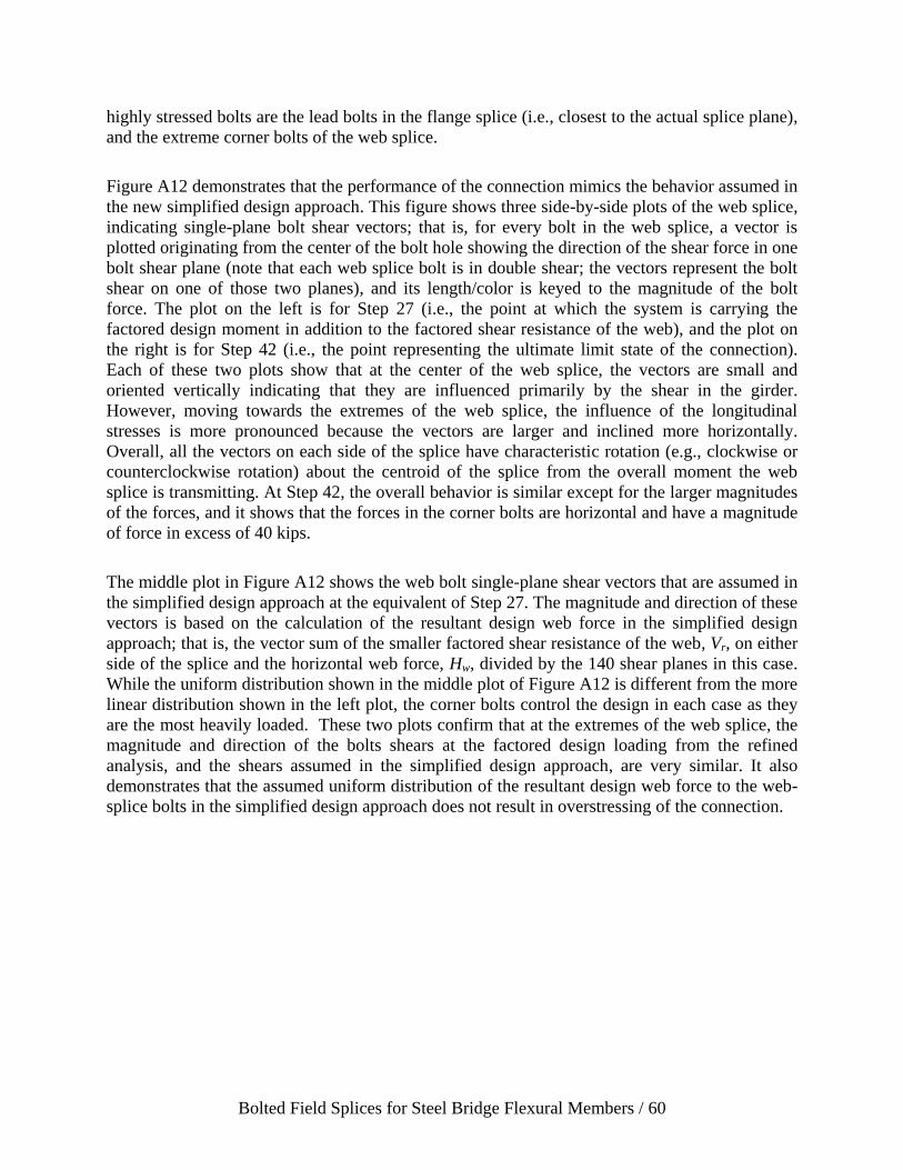
Bolted Field Splices for Steel Bridge Flexural Members / 60
highly stressed bolts are the lead bolts in the flange splice (i.e., closest to the actual splice plane),
and the extreme corner bolts of the web splice.
Figure A12 demonstrates that the performance of the connection mimics the behavior assumed in
the new simplified design approach. This figure shows three side-by-side plots of the web splice,
indicating single-plane bolt shear vectors; that is, for every bolt in the web splice, a vector is
plotted originating from the center of the bolt hole showing the direction of the shear force in one
bolt shear plane (note that each web splice bolt is in double shear; the vectors represent the bolt
shear on one of those two planes), and its length/color is keyed to the magnitude of the bolt
force. The plot on the left is for Step 27 (i.e., the point at which the system is carrying the
factored design moment in addition to the factored shear resistance of the web), and the plot on
the right is for Step 42 (i.e., the point representing the ultimate limit state of the connection).
Each of these two plots show that at the center of the web splice, the vectors are small and
oriented vertically indicating that they are influenced primarily by the shear in the girder.
However, moving towards the extremes of the web splice, the influence of the longitudinal
stresses is more pronounced because the vectors are larger and inclined more horizontally.
Overall, all the vectors on each side of the splice have characteristic rotation (e.g., clockwise or
counterclockwise rotation) about the centroid of the splice from the overall moment the web
splice is transmitting. At Step 42, the overall behavior is similar except for the larger magnitudes
of the forces, and it shows that the forces in the corner bolts are horizontal and have a magnitude
of force in excess of 40 kips.
The middle plot in Figure A12 shows the web bolt single-plane shear vectors that are assumed in
the simplified design approach at the equivalent of Step 27. The magnitude and direction of these
vectors is based on the calculation of the resultant design web force in the simplified design
approach; that is, the vector sum of the smaller factored shear resistance of the web, Vr, on either
side of the splice and the horizontal web force, Hw, divided by the 140 shear planes in this case.
While the uniform distribution shown in the middle plot of Figure A12 is different from the more
linear distribution shown in the left plot, the corner bolts control the design in each case as they
are the most heavily loaded. These two plots confirm that at the extremes of the web splice, the
magnitude and direction of the bolts shears at the factored design loading from the refined
analysis, and the shears assumed in the simplified design approach, are very similar. It also
demonstrates that the assumed uniform distribution of the resultant design web force to the web-
splice bolts in the simplified design approach does not result in overstressing of the connection.

Bolted Field Splices for Steel Bridge Flexural Members / 61
Figure A2. Von Mises stress contours at Step 27.
Figure A3. Von Mises stress contours at Step 42.

Bolted Field Splices for Steel Bridge Flexural Members / 62
Figure A4. Longitudinal stress contours at Step 27.
Figure A5. Longitudinal stress contours at Step 42.

Bolted Field Splices for Steel Bridge Flexural Members / 63
Figure A6. Shear stresses at Step 27.
Figure A7. Shear stresses at Step 42.

Bolted Field Splices for Steel Bridge Flexural Members / 64
Figure A8. Plastic strains at Step 27. Note legend maximum of 1%
strain.
Figure A9. Plastic strains at Step 42. Note legend maximum of
10% strain.
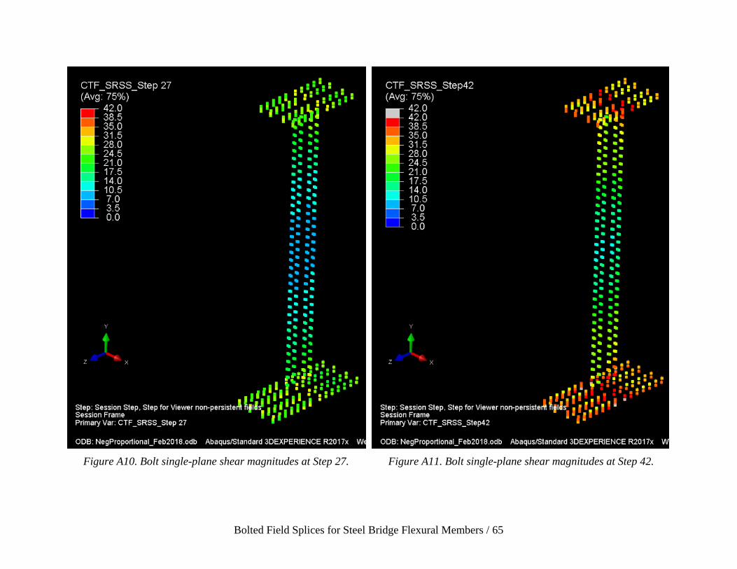
Bolted Field Splices for Steel Bridge Flexural Members / 65
Figure A10. Bolt single-plane shear magnitudes at Step 27.
Figure A11. Bolt single-plane shear magnitudes at Step 42.

Bolted Field Splices for Steel Bridge Flexural Members / 66
Figure A12. Bolt shear vectors in web splice (single shear plane) at Step 27 (left), based on the design assumption (middle), and at
Step 42 (right).