Seismic performance of cold-formed steel bolted moment ...
22
1 Seismic performance of cold‐formed steel bolted moment connections with bolting friction‐slip fusing mechanism Jun Ye 1 , Seyed Mohammad Mojtabaei 2 *, Iman Hajirasouliha 3 1 Lecturer, Department of Architecture and Civil Engineering, University of Bath, UK 2 * PhD candidate, Department of Civil and Structural Engineering, University of Sheffield, UK; (corresponding author). E‐mail: [email protected]; 3 Senior Lecturer, Department of Civil and Structural Engineering, University of Sheffield, UK Abstract: Typical cold‐formed steel (CFS) moment‐resisting connections generally have limited ductility and energy dissipation capacity due to the low local/distortional buckling resistance of thin‐walled CFS elements, and therefore, may not be suitable for seismic applications. This study aims to investigate the efficiency of using bolting friction‐slip fusing mechanism to improve the seismic performance of CFS bolted beam‐to‐column connections. To simulate the hysteretic moment–rotation behaviour and failure modes of selected connections, experimentally validated finite element models are developed using ABAQUS by taking into account the geometrical imperfections, nonlinear material properties and characteristics of the bolting fusing system. The models are then used to investigate the effects of CFS beam cross‐sectional shape and classification, bolt arrangement, and slip resistance on the cyclic behaviour of the connections. It is shown that using bolting friction‐slip fuse mechanism can significantly increases (up to 200%) the energy dissipation capacity, damping coefficient and ductility of the connections especially for CFS beams with thinner plates. Finally, the best design configurations are identified to improve the seismic performance of the CFS connections under strong earthquakes. Key words: Cold‐formed steel; Bolted moment connection; Cyclic behaviour; Friction‐slip fusing mechanism; FE analysis
Transcript of Seismic performance of cold-formed steel bolted moment ...

1
Seismic performance of cold‐formed steel bolted moment connections
with bolting friction‐slip fusing mechanism
Jun Ye1, Seyed Mohammad Mojtabaei2*, Iman Hajirasouliha3
1 Lecturer, Department of Architecture and Civil Engineering, University of Bath, UK
2* PhD candidate, Department of Civil and Structural Engineering, University of Sheffield, UK;
(corresponding author). E‐mail: [email protected];
3 Senior Lecturer, Department of Civil and Structural Engineering, University of Sheffield, UK
Abstract:
Typical cold‐formed steel (CFS) moment‐resisting connections generally have limited
ductility and energy dissipation capacity due to the low local/distortional buckling resistance
of thin‐walled CFS elements, and therefore, may not be suitable for seismic applications.
This study aims to investigate the efficiency of using bolting friction‐slip fusing mechanism to
improve the seismic performance of CFS bolted beam‐to‐column connections. To simulate
the hysteretic moment–rotation behaviour and failure modes of selected connections,
experimentally validated finite element models are developed using ABAQUS by taking into
account the geometrical imperfections, nonlinear material properties and characteristics of
the bolting fusing system. The models are then used to investigate the effects of CFS beam
cross‐sectional shape and classification, bolt arrangement, and slip resistance on the cyclic
behaviour of the connections. It is shown that using bolting friction‐slip fuse mechanism can
significantly increases (up to 200%) the energy dissipation capacity, damping coefficient and
ductility of the connections especially for CFS beams with thinner plates. Finally, the best
design configurations are identified to improve the seismic performance of the CFS
connections under strong earthquakes.
Key words: Cold‐formed steel; Bolted moment connection; Cyclic behaviour; Friction‐slip
fusing mechanism; FE analysis

2
1. Introduction
Cold‐formed steel (CFS) sections are produced by rolling or pressing of thin‐walled steel
sheets to form open cross sectional shapes at ambient temperature (cold working). In
general, CFS elements can be more economical and efficient compared to their hot‐rolled
counterparts due to their inherent advantages such as high strength‐to weight ratio, ease
and speed of construction, and especially greater flexibility in manufacturing various cross‐
sectional profiles and sizes [1‐3]. Traditionally, the use of CFS sections as main structural
components has been restricted to shear walls (stud wall systems) consisting of vertical
studs, diagonal braces and top and bottom tracks. The seismic behaviour of shear walls with
different configurations and bracing systems has been investigated experimentally by
several full‐scale cyclic and monotonic tests [4‐6]. While there is a consensus that most of
the shear wall systems can carry lateral and vertical loads up to the drift limits required by
majority of seismic codes, typical CFS shear walls may exhibit poor ductility due to the
premature buckling of the stud elements [7].
In modern construction, CFS sections are increasingly being used as main structural
elements in other structural systems such as moment‐resisting frames in warehouses,
hangars, and pitched roof industrial and agricultural buildings. Previous studies indicated
that, in general, CFS bolted moment connections are capable of providing acceptable
flexural strength and stiffness, and adequate deformation capacity for seismic applications
[3, 8]. However, typical CFS bolted moment connections may exhibit relatively low ductility
and energy dissipation capacity, especially when the width‐to‐thickness ratio of the CFS
elements increases [9]. This limitation is a major obstacle for widespread application of CFS
moment‐resisting frames in multi‐storey buildings in seismic regions.
Seismic design of structures normally relies on inelastic deformations through hysteretic
behaviour, leading to damage and permanent deformation of structural elements, and

3
hence high repair costs, following a strong earthquake event. In steel construction, using
friction‐slip fusing mechanism is known as an alternative seismic design approach,
implemented to absorb the energy of the earthquake and consequently reduce and control
the damage to the structural elements [10] . In general, development of plasticity in the
connection zone of CFS moment‐resisting frames cannot be easily achieved due to the
higher vulnerability of thin‐walled elements (i.e. with large width‐to‐thickness ratio) to
local/distortional buckling compared to their hot‐rolled counterparts [9]. Therefore,
accommodating friction‐slip fusing mechanism in CFS bolted moment connections to
dissipate the earthquake input energy can provide a practical solution to improve the
seismic performance of CFS moment‐resisting frames. In practice, friction‐slip fusing
mechanism can be easily activated in bolted moment connection by providing appropriate
bolt tightening and detailing [10], which is presented schematically in Fig. 1.
A
A
Guessetplate FF
Beam FF
Plate
BoltshankSlippage
Gap
FF
Bearing
Plate
Column
Full‐scaleconnection
Fig. 1: Slippage and bearing behaviour of a single bolt against steel plate in a CFS bolted
moment connection
The behaviour of beam‐to‐column CFS bolted moment‐resisting connections with gusset
plates has been investigated experimentally and numerically under monotonic and cyclic
loading conditions [10‐16]. It was found that the typical behaviour of CFS bolted connections
can be characterized by a linear deformation phase followed by a slip range, a strength
hardening response due to the bearing action of bolt shank against the steel sheet and

4
finally a strength degradation phase caused by the local buckling of the connected CFS
elements. It was also demonstrated that, though CFS moment‐resisting connections usually
exhibit a semi‐rigid behaviour, they can generally provide enough stiffness and moment
resistance for low to medium rise moment frames [15]. In another study, Lim et al. [3]
examined experimentally the ultimate strength of bolted moment‐connections for CFS
channel‐sections. The tested specimens included apex and eaves connections, and it was
concluded that the connections exhibit a semi‐rigid behaviour due to bolt‐hole elongation in
the thin‐walled steel sheet. Analytical work by Lim et al. [8] indicated that bolt‐group sizes in
CFS connections can also have a significant impact on the bending capacity of the connected
sections. Based on the above studies, it can be concluded that the ductility and energy
dissipation capacity of CFS bolted connections depend mainly on the following four factors:
(a) bolt distribution and bolt tightening (bolt slippage); (b) material yielding and bearing
around the bolt holes; (c) yielding lines resulting from the buckling of the CFS cross‐sectional
plates; and (d) cross‐sectional shapes of the CFS beam elements. The effects of these factors
will be investigated in this study. This paper aims to develop more efficient design
configurations for CFS bolted moment connections with bolting friction‐slip fusing
mechanism to improve their ductility and energy dissipation capacity, and therefore,
facilitate their application in earthquake resistant frames. Detailed GMNIA FE models are
developed by taking into account material nonlinearity and initial geometrical imperfections.
To model the friction‐slip fusing mechanism, equivalent connector elements are used to
simulate the bearing behaviour of a single bolt against CFS plate as well as the slip action of
the bolts. The detailed FE models are then verified against experimental results of CFS
bolted connections under cyclic loading using test data by Sabbagh et al. [10]. Subsequently,
an extensive parametric study is conducted to investigate the effects of a wide range of
design parameters including cross‐sectional shape and classification, slip resistance, and bolt

5
arrangement on the behaviour of the connections. The results are then used to identify the
most efficient design solutions for CFS bolted moment connections with fuse mechanism.
2. Experimentally Validate FE models
The results of previous studies have demonstrated the adequacy of detailed Finite
Element (FE) models to predict the behaviour of CFS connections under monotonic [17, 18]
and cyclic loading [19]. This section describes the details of the FE models developed in this
study, including the model proposed for simulating bolting friction‐slip fusing mechanism in
a connection assembly.
2.1Elementtype,loadingandboundaryconditions
The general‐purpose S8R element (8‐noded quadrilateral shell element with reduced
integration) in ABAQUS [20] element library is adopted to model the CFS connection
components. Following a comprehensive mesh sensitivity study, the mesh size 20×20 mm is
used as it could provide a balance between accuracy and computational efficiency. The
boundary conditions are applied according to the details of the test set‐up presented by
Sabbagh et al. [10], as shown in Fig. 2. The translational degrees of freedom UX and UY on
top face of the back‐to‐back channel column are restrained, while the bottom of the column
is considered to be pinned. Since the back‐to‐back beam was assembled with bolts and filler
plates in the experimental tests, the web lines are connected together in the UX, UY and UZ
direction using the “Tie” constraint in ABAQUS [20]. Lateral bracing in the X direction is
imposed at the locations of lateral frames used in the experiments to prevent lateral
torsional buckling of the beam element [10] (see Fig. 2). While it was previously shown that
the deformation of panel zone can also contribute to the rotational response of bolted
moment connections [21, 22], due to the use of a thicker cross‐section and column stiffeners
in this study, it is assumed that the panel zone remains elastic during cyclic loading. This is
consistent with the experimental results reported by Sabbagh et al. [10].

6
Fig. 2: Boundary conditions of the FE model for beam‐column connection
To apply the external cyclic load, the nodes of the beam end section are coupled to the
reference point placed on the cross‐sectional centroid. A tip displacement corresponding to
rotation of the connection is applied at the reference point. The AISC 341‐16 [23] cyclic
loading regime used in the reference experimental tests [10] is adopted as shown in Fig. 3.
The displacement control nonlinear FE analyses are conducted using Static General Analysis
available in ABAQUS [20] library.
Fig. 3: Cyclic loading regime for the reference test [10] and numerical study
‐150
‐100
‐50
0
50
100
150
0 5 10 15 20 25 30 35 40
Displacement (m
m)
Cycles
RP
Lateral bracing in X direction
Coupling (UX=UY=0)
Coupling (UX=UY=UZ=0)
F Coupling (UX=URY=URZ=0)
Tie (UX=UY=UZ)
RP
RP

7
2.2Materialproperties
The stress‐strain behaviour of CFS plate is simulated using the constitutive model
suggested by Haidarali and Nethercot [24]. This stress‐strain relationship consists of a
Ramberg‐Osgood equation up to the 0.2% proof stress, followed by a straight line with a
slope of / 100E (E is the elastic modulus) as shown below:
0.20.2
0.20.2 0.2
= 0.002
100( )=
n
forE
forE
(1)
where 0.2 is the 0.2% proof stress, 0.2 is the strain corresponding to the 0.2% proof
stress and n is a parameter determining the roundness of the stress‐strain curve. Based on
the results of coupon tests conducted by Sabbagh et al. [10], the parameter n is taken as 10,
0.2 310MPa , 210E GPa and the ultimate strain is considered to be 0.08. Fig. 4
demonstrates the good agreement between the stress‐strain curve from the coupon tests
[10] and the material model used in this study.
Fig. 4: Stress‐strain curve used in the FE model.
0
100
200
300
400
500
0 0.02 0.04 0.06 0.08
σ(M
Pa)
ɛ
Eq.(2)
Coupon Test

8
2.3Imperfection
As mentioned before, no global buckling (lateral‐torsional buckling) was observed in the
tested reference beam [10] due to the lateral bracing system used in the test setup.
Therefore, either a local or a distortional imperfection is incorporated into the FE model,
depending on which mode has the lower critical buckling resistance. The imperfection
magnitude for the thickness of steel sheet (t) less than 3mm is taken as 0.34t and 0.94t for
the local and distortional imperfections, respectively, based on the work conducted by
Schafer and Pekӧz [25]. For steel sheet thickness (t) larger than 3mm, the imperfection
magnitude is considered to be 0.3 st as suggested by Walker [26], where s is the cross‐
sectional slenderness. The cross‐sectional shape of the imperfection is generated by using an
eigenvalue buckling analysis in ABAQUS. The first buckling mode of the CFS connection is
then used to find the general shape of the local and distortional imperfections. In the case of
monotonic load, a tip displacement in the Z direction is used to conduct the eigenvalue
buckling analysis, which results in a unsymmetrical mode for including imperfection (see Fig.
5 (a)). However, in the case of cyclic loading, there is a need to generate a symmetrical
imperfection mode (see Fig. 5 (b)). To generate this, eigenvalue buckling analysis is
performed on the both +Z and ‐Z directions, and the mixture of the first buckling mode
shapes is incorporated as an initial state of the CFS bolted moment connection.
Fig. 5: First buckling mode shape in the cases of: (a) monotonic load (b) cyclic load.

9
2.4boltmodelling
In this study, a simplified connection element based to the concept of “component
method” [27] is adopted to simulate the CFS connection behaviour. The slippage behaviour
of the bolted connections depends mainly on the distribution of initial friction forces, which
in return rely on the bolt pretension force bP for a given applied torque and friction
coefficient of the contact surfaces. Therefore, the bolt slip resistance slipF can be
expressed as [15] :
slip b bF P n (2)
where is the mean frictional coefficient given as 0.19 for galvanised steel surfaces [28],
and bn is the number of slip planes.
The point‐based “Fastener” using a two‐layer fastener configuration found in ABAQUS
library [20] is employed to model individual bolts (see Fig. 6). Each layer is connected to the
CFS beam and gusset plate using the connector element to define the interaction properties
between the layers. To model the connector element, a “physical radius” r is defined to
represent the bolt shank radius and simulate the interaction between the bolt and the nodes
at the bolt‐hole perimeter. This reduces the stress concentration around the nodes at the
bolt positions and, hence, improves the convergence of the cyclic nonlinear analysis.
Fig. 6: FE model of the beam‐column connection with fastener definition
Fastener element
Beam or column node
Beam or column node
Gusset plate node
Physical radius

10
As shown in Fig. 7 (a), each fastener point is connected to the CFS steel plates using a
connector element that couples the displacement and rotation of each fastener point to the
average displacement and rotation of the nearby nodes. The friction‐slip fusing behaviour is
assigned to the connector element using “Cartesian” with 3 translational degrees of freedom,
characterised by a parallel combination of “Elasticity”, “Friction” and “Stop” behaviours, as
shown in Fig. 7 (b). To model “Elasticity” characteristic, a rigid behaviour is assigned to the
local coordinate system corresponding to the shear deformation of the bolts. The friction
coefficient and internal contact force bP in Eq. (2) are used to model “Friction”
behaviour. The “Stop” behaviour is thereby defined to limit the range of slip movement
within the bolt‐hole clearance (typically ±1mm for standard bolts by assuming that the bolt
shanks are centrally positioned). The connector behaviour is schematically presented in Fig.
7 (c).
Fig. 7: Single bolt modelling in ABAQUS: (a) definition of fastener; (b) components defined in
a connector section; and (c) slip‐bearing relationship defined in a connector section
(a) (b)
(c)

11
Based on the above discussion, the connector behaviour is characterised as follows:
(a) The connector is reasonably assumed to be rigid up to the slip resistance slipF before the
slippage of bolts (fusing mechanism) is activated. It should be noted that no slippage can be
captured in FE analysis if the internal bolt force is smaller than the critical slip resistance.
(b) Connector shear force is gradually developed and overcomes frictional resistance ( slipF ),
and subsequently relative slippage between the two plates in each layer of the CFS
connection starts to happen (see Fig. 7 (a)). The slippage will stop when the bolt shank is in
contact with the hole perimeter surface.
(c) The bearing stiffness is infinite when the relative displacement between two fastener
points is larger than slip .
2.5ValidationofFEmodels
Fig. 8 shows the moment‐rotation hysteresis behaviour of the CFS connection test B2
[29], which is used to validate the developed detailed FE models. This connection is
mobilised with a friction‐slip fusing mechanism, which activates the bolt slippage before the
buckling of CFS beam profile. Based on Eq. (2), the pretension force in the bolts is directly
related to the applied torque. In the reference experimental test, the friction force between
the steel plates was provided through pre‐tensioning the bolts with a torque of 240 N∙m [29].
The torque was controlled by using a torque wrench and the preloading‐torque relationship
was established by using a pretension measuring machine [29].
The simplified bolt model in Fig. 7 is used for modelling of the bolts, and the physical
radius is defined in accordance with the bolt shank radius equal to 9 mm [29]. To partially
account for the effect of bolt elongation of the plate holes, the range of slippage of the stop
element in Fig. 7 is increased from 1mm to 2mm in the first lines of the bolts [10]. The
experimental measurements and FE responses subjected to both monotonic and cyclic
loading are presented in terms of moment‐rotation (M‐Ɵ) hysteretic curves in Fig. 8. For

12
better comparison, Fig. 9 also compares the failure shape of the modelled connection under
cyclic loads with the experimental observations. Generally, the numerical simulation under
cyclic load is in a very good agreement with the corresponding experimental results.
However, the M‐Ɵ curve subjected to monotonic load shows less strength degradation than
the response under cyclic load. This is due to the cyclic deterioration effects which cannot be
captured in the case of monotonic loading. It is worth noting that reduced slip resistance
was observed after a number of cycles in the experiment [10]. This is mainly due to the fact
that the high torque applied in the assembling process affects the contact surface between
the plates after a number of loading cycles and the new slippage force will be then stabilised.
The slippage resistance corresponding to the normal surface contact condition defined in Eq.
(2) proved to be reasonable in the numerical validation of FE modelling against tested results
in this study. It is shown in Fig. 9 that the developed numerical model can capture
successfully the shape and the position of local/distortional buckling in the CFS beam as well
as bolting friction‐slip fusing mechanism. These results validate the modelling approach used
in this study.
(a) (b)
Fig. 8: Comparison between tested and analysed moment‐rotation curves of connection B2
(tested by Bagheri et al. [10]): (a) monotonic load and (b) cyclic load

13
(a) (b) (c)
Fig. 9: Comparison between tested and analysed buckled shape of connection B2: (a)
experimental cyclic load (adopted from [29]), (b) FE monotonic load, and (c) FE cyclic load
3. General response of connections with and without friction‐slip fusing
mechanism
CFS bolted moment connections with bolting friction‐slip fusing mechanism can be
considered as friction dampers, which can reduce damage in structural elements by
absorbing a part of earthquake input energy and also decrease maximum stresses in
connection zones by providing a fusing mechanism. To show the efficiency of the proposed
system, the flexural deformation and the von‐Mises stress distribution of the connections
with and without bolting friction‐slip fusing mechanism are extracted from FE analysis and
compared in Fig. 10. While the details of the FE models for both types of connections are
similar (see Section 2), bolt slippage is prevented in the connections with no friction‐slip fuse
mechanism by using very high pretension force values [30]. The results in Fig. 10 confirm
that using the proposed fusing mechanism can significantly reduce the stress concentrations
in the connection zone.
In general, the flexural behaviours of a typical CFS bolted moment connection and the
one which friction‐slip mechanism is mobilised through slippage of the bolts can be
distinguished in different phases as shown Fig. 11. The first phase (O‐A) occurs during initial
loading of the connection corresponding to the elastic performance of the connection.
During this phase, the bearing action of the bolts occurs for both types of connection.
However, in the connection with friction‐slip fuse the bearing action is interrupted at slip

14
moment Mslip (point A), which corresponds to the beginning of bolts slippage phase. The
total slippage ( b ) in the connection can be determined based on the summation of bolt
holes clearance and elongation. It will be discussed in section 4 that the slip moment (Mslip)
and bolt clearance are the key parameters which affect the energy absorbing capability of
friction‐slip fusing systems.
As can be seen in Fig. 11, point B corresponds to the position that the bearing action of
the bolts is re‐activated. Points C and C’ show the peak moments (Mp) of the CFS bolted
moment connections with and without bolting fusing mechanism, respectively. In the final
stage, there is a sudden loss of strength for both connections due to local buckling of the
beam element. In this study, it was assumed that the ultimate moment of both connections
(Mu) is reached at 20% drop from peak moment (points D and D’ for connections with and
without friction‐slip fusing mechanism, respectively).
Fig. 10: Von‐Mises stress distribution and coressponsing damage in the (a) normal, and (b)
mobilised friction‐slip connections
(a)
(b)

15
Fig. 11: Moment‐rotation relationships of CFS connections with and without bolting fusing
mechanism
Fig. 12 compares the cyclic hysteretic performance of the CFS bolted moment
connection without and with friction‐slip fuse mechanism under cyclic loading regime shown
in Fig. 3. The results indicate that, similar to monotonic behaviour, using friction‐slip fusing
mechanism provides a horizontal shift in each cycle of hysteretic moment‐rotation curve
while the peak and ultimate moments are not considerably affected. This will be discussed in
more detail in the following sections.
Fig. 12: Example of comparison between cyclic hysteretic performance of the CFS bolted
moment connection without and with friction‐slip fuse mechanism

16
4.Keydesignparameters
The main design parameters examined are beam cross‐sectional shape, plate thickness
(or cross‐sectional slenderness), bolt configuration and bolt slip load resistance. Considering
the capabilities of the cold‐rolling and press‐braking processes to provide cross sections with
intermediate stiffeners or folded plates, four different geometries including flat, stiffened,
folded and curved shaped channel cross‐sections are selected for the parametric study, as
shown in Fig. 13. For each cross‐section, four different plate thicknesses of 1, 2, 4, 6 mm are
used. The selected cross‐sections have the same total plate width, and therefore, use the
same amount of structural material. Moreover, to investigate the effect of different flange
shapes, all cross‐sections are designed to have a similar web slenderness ratio. It should be
mentioned that the curved‐flange cross‐section in this study is less practical and is mainly
used for comparison purposes and verification of analytical models with the reference
experimental results [10]. It should be noted that thin walled sections with curved or folded‐
flange cross sections may be sensitive to crippling due to support transvers actions from
joints and purlins, which should be considered in the design process of these elements. Since
bolt configuration can also affect the stress field distribution of bolted moment connections
[8], three types of bolt configurations including circle, diamond and square shapes are
selected, as shown in Fig. 14. To increase the efficiency of the proposed connection, the
number of bolts and their arrangement were also optimised in this study. As a result, the
number of required bolts was reduced from 16 in the reference experimental tests [10] to 9
bolts. It is worth mentioning that in common construction practice the circular bolt
arrangement may be less practical compared to square and diamond arrangements,
however, in this study it is investigated for comparison purposes.

17
Flat‐flange Stiffened‐flange Curved‐flange Folded‐flange
Fig. 13: Details of the back‐to‐back beam sectional dimensions with L=2000 mm
Fig. 14: Different bolt configurations
4.1Cross‐sectionalclassification
Eurocode 3 (EC3) categorizes cross‐sections into four different classes (1, 2, 3 and 4)
according to their susceptibility to local buckling. This classification can be conceptually
conducted by using moment‐rotation behaviour (M‐ϴ) of the cross‐section, where My, Mp
and Mu represent yield moment, plastic moment and peak moment capacity, respectively
(see Fig. 15). Class 4 cross‐sections generally experience local buckling before attaining the
yield moment capacity (Mu<My). In class 3 cross‐sections, the stress in the extreme
compression fibre reaches the yield strength, but local buckling prevents the development
of the plastic moment resistance (My <Mu<Mp). Class 2 represents cross‐sections that reach
to their plastic moment capacity, but their ultimate plastic rotation is limited by occurrence
of local plastic buckling of compression part (Mp<Mu). Class 1 cross‐sections can develop
their full plastic moment capacity with adequate plastic rotation (Mp<Mu). According to the
Bolt configuration‐1 Bolt configuration‐2 Bolt configuration‐3
Square Circle Diamond

18
FE results, in this study all cross sectional shapes with 1, 2, 4 and 6 mm plate thickness are
classified as class 4, 3, 2 and 1, respectively [30].
Fig. 15: EC3 cross‐sectional classification definition
4.2Effectofvariousboltslipresistance
To evaluate the effect of using various bolt slip resistance on the global moment‐
rotation behaviour of the connections, a range of bolt pretensions are applied on the
connections with the beam flat‐flange class 1 (t=6mm). The slip resistance design values are
selected to be at least equal to the allowable slip resistance determined according to ASTM
A325 [31] using the following equation:
1.13n b mR N T (3)
where nR is slip resistance of the connection, is the frictional coefficient, bN is the
number of bolts, and mT is minimum bolt pretension. Monotonic analyses are then carried
out on the connections with three different bolts pretensions using “Static General” analysis
available in ABAQUS library [20]. Bolt pretensions are selected to be: mT =90 kN which
activates the bolt slippage while the CFS beam is still in the elastic behaviour range, mT =270
kN which activates the slippage of the bolts when CFS is in its inelastic behaviour range, and
fully clamped beam (no friction‐slip fuse). As shown in Fig. 16, the adopted fuse mechanism
generally generates a horizontal shift in the moment‐rotation curve while the global
behaviour of the connection is very similar to the no slippage connection. It should be noted
19
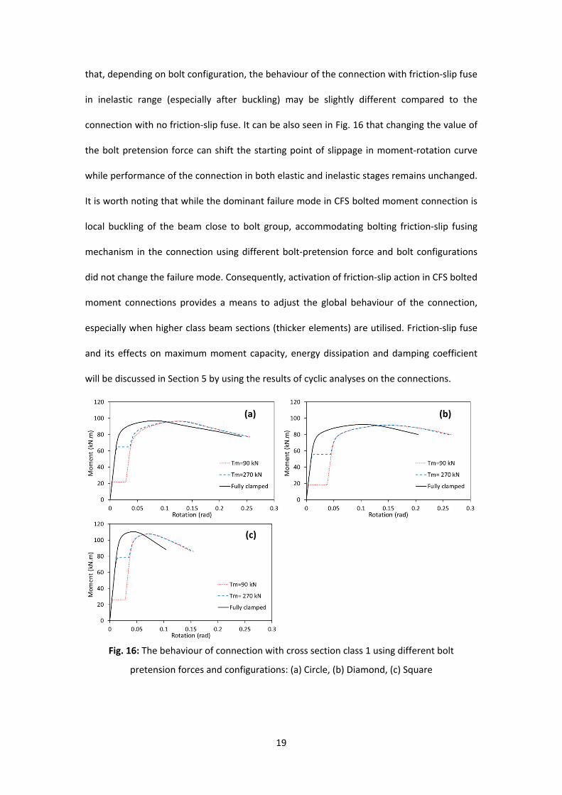
that, depending on bolt configuration, the behaviour of the connection with friction‐slip fuse
in inelastic range (especially after buckling) may be slightly different compared to the
connection with no friction‐slip fuse. It can be also seen in Fig. 16 that changing the value of
the bolt pretension force can shift the starting point of slippage in moment‐rotation curve
while performance of the connection in both elastic and inelastic stages remains unchanged.
It is worth noting that while the dominant failure mode in CFS bolted moment connection is
local buckling of the beam close to bolt group, accommodating bolting friction‐slip fusing
mechanism in the connection using different bolt‐pretension force and bolt configurations
did not change the failure mode. Consequently, activation of friction‐slip action in CFS bolted
moment connections provides a means to adjust the global behaviour of the connection,
especially when higher class beam sections (thicker elements) are utilised. Friction‐slip fuse
and its effects on maximum moment capacity, energy dissipation and damping coefficient
will be discussed in Section 5 by using the results of cyclic analyses on the connections.
Fig. 16: The behaviour of connection with cross section class 1 using different bolt
pretension forces and configurations: (a) Circle, (b) Diamond, (c) Square
(a) (b)
(c)

20
5. Efficiency of CFS bolted moment connections with friction‐slip
fusingmechanism
In this section, the results of the comprehensive parametric study are used to identify
the most efficient design solutions for CFS bolted moment connections with friction‐slip
fusing mechanism using different response parameters.
5.1Moment‐rotationbehaviour
In this section, the flat‐flange channels with various thicknesses (1, 2, 4 and 6 mm) and
circle distribution of the bolts is selected to show the typical cyclic response of the
connections mobilised with friction‐slip fusing system (Fig. 17). The cyclic moment‐rotation
envelope is specified in both positive and negative rotations by plotting the locus of peak
moment points at the first cycle of each load amplitude. It should be noted that, unlike the
monotonic moment rotation backbone curve, the cyclic moment‐rotation envelope can take
into account the strength degradation due to cyclic loading as observed in the previous
experimental tests on CFS elements and connections [29, 32, 33]. The rotation of the
connection was quantified as the ratio of beam tip displacement to the length of the beam
up to the gusset plate. In the following sections, the moment‐rotation results are used to
determine different performance parameters such as moment capacity, energy dissipation,
equivalent viscous damping coefficient, and ductility ratio. It is worth mentioning that the
dominant mode of failure in the selected connections with and without friction‐slip is always
local buckling in the CFS beam. However, the deformation of buckled area of the beam is
less intensified when slip action is activated in the connection (see Fig. 10).

21
(a) t=1 mm (b) t=2 mm
(c) t=4 mm (d) t=6 mm
Fig. 17: Moment‐rotation cyclic relationship and envelope curve of the connections with flat‐
flange beam section and circular bolt arrangement
5.2Momentcapacityoftheconnections
Fig. 18 shows the maximum moment capacity of both connections with and without
bolting friction‐slip fuse, indicating the effect of bolt slippage is generally negligible on the
flexural capacity of the connections regardless of the beam cross‐sectional class. The minor
differences can be attributed to the fact that after bolt slippage the centre of rotation shifts
from the centre of the bolts, leading to a small change in the maximum flexural capacity of
the connections. As shown in Fig. 18, the cross‐sectional class of the CFS beam elements and
the arrangement of the bolts seem to be the most important design parameters affecting
the capacity of the connections. In general, using a square bolt arrangement leads to a
higher bending moment capacity especially in the case of CFS beam elements with class 1
and 2 (6 mm and 4 mm), where up to 32% increase is observed compared to the other bolt
arrangements. While it was previously shown that bent flange sections can provide
noticeably higher moment capacity compared to standard flat‐flange sections [10, 34], the

22
results of this study indicate that using bent flange sections can increase the capacity of the
connections by less than 10%. This is referred to two main reasons: (i) effect of bi‐moment
generated due to presence of bolts [8], and (ii) using channels with deep web generally
reduces the effects of the flange on the moment capacity of the connections.
Fig. 18: Moment capacity of CFS connections as a function of bolt configuration and cross‐
section class (C1, C2, C3, and C4 are cross‐section classes 1, 2, 3 and 4, respectively)
5.3FEMAbi‐linearidealisationmodel
To characterize the cyclic behaviour of the CFS bolted moment connections, the idealised
bi‐linear models recommended by FEMA‐356 [35] are developed based on the cyclic
moment‐rotation envelopes (see Section 5.1). As shown in Fig. 19, the FEMA proposed
models use an ideal bilinear elastic plastic curve to represent the non‐linear behaviour of an
assembly by incorporating an energy balance approach. The yield rotation (y) is determined
on the condition that the secant slope intersects the actual envelope curve at 60% of the
nominal yield moment (My), while the area enclosed by the bilinear curve is equal to that
enclosed by the original curve bounded by the target displacement (t). The adopted model