BOLTED END-PLATEJOINTS EXPERIMENTAL $TUDY ON THE …
18
EXPERIMENTAL $TUDY ON THE CYCLIC BEHAVIOUR OF BOLTED END-PLATE JOINTS $ándor Ádány*, Luis Calado** and László Dunai*** *Assistant, Department of Stmctural Mechanics, Technical University of Budajest, Hungary **Associate Professor, DECivil, Instituto Superior Técnico, Lisbon, Portugal ***Assocjate Professor, Department of Steel Strnctures, Technical University ofBudapest, Hungaiy • ABSTRACT In this paper an experimental st;idy is reported perforhied on end-plate type joints. The test arrangement represents a column-basejoint oja steeiframe. Altogether six specimens were testec, each of them subject to cyclic loading. The speciméns were carefíilly designea’ by performing detailed preliminary calcídations, so that they would presem’ the typical behaviour types of end-ptate joints. On the basis of the experimentally establishëd moment rotation relationshi the cyclic characteristics of each specimen have been calculated and compared to one another. The results are evahiated qïtalitative and quantitative conclusions are drawn. • 1 INTRODUCTION End-plate-type joints are widely used in steel frame structures. These joints can connect either two steel elements (like beam-to-colunm, beam-to-beam or column tó-column joints) or a steel and a concrete/reinforced concrete element (like column-base joints or joints of a steel beam and a reinforced concrete colurnn). lhe main advantage ofthis tye ofjoint is in the production and mounting, at the sarne tirne, • however, their application resuits in a more complicated structural behaviour and, consequently, requires more complex design. In the recent decade lots of investigation (both numerical and experimental) have been perforrned to analyse the behaviour of the different kinds of end-plate j oints, and to develop appropriate numerical modeis for the everyday engineering practice. As a result ofthese investigations, focused mainly on the monotonic behaviour, calculation rnethods have been developed and introduced to the new European steel code for steel-to-steei joints (Eurocode 3, 1991), as well as design tables are worked out for colurnn-bases (Wald et ai, 1994). lo the cyclic behaviour, however, rnuch iess efforts have been devoted. Nevertheless, certain number of experimental programs have been 7
Transcript of BOLTED END-PLATEJOINTS EXPERIMENTAL $TUDY ON THE …
EXPERIMENTAL $TUDY ON THE CYCLIC BEHAVIOUR OFBOLTED END-PLATE JOINTS
$ándor Ádány*, Luis Calado** and László Dunai****Assistant, Department of Stmctural Mechanics, Technical University of Budajest, Hungary
**Associate Professor, DECivil, Instituto Superior Técnico, Lisbon, Portugal***Assocjate Professor, Department of Steel Strnctures, Technical University ofBudapest, Hungaiy
• ABSTRACT
In this paper an experimental st;idy is reported perforhied on end-plate type joints. The testarrangement represents a column-basejoint oja steeiframe. Altogether six specimens weretestec, each of them subject to cyclic loading. The speciméns were carefíilly designea’ byperforming detailed preliminary calcídations, so that they would presem’ the typicalbehaviour types of end-ptate joints. On the basis of the experimentally establishëd momentrotation relationshi the cyclic characteristics of each specimen have been calculated andcompared to one another. The results are evahiated qïtalitative and quantitative conclusionsare drawn.
• 1 INTRODUCTION
End-plate-type joints are widely used insteel frame structures. These joints canconnect either two steel elements (likebeam-to-colunm, beam-to-beam or columntó-column joints) or a steel and aconcrete/reinforced concrete element (likecolumn-base joints or joints of a steel beamand a reinforced concrete colurnn). lhemain advantage ofthis tye ofjoint is in theproduction and mounting, at the sarne tirne,
• however, their application resuits in a morecomplicated structural behaviour and,consequently, requires more complexdesign.
In the recent decade lots of investigation(both numerical and experimental) havebeen perforrned to analyse the behaviour ofthe different kinds of end-plate j oints, and todevelop appropriate numerical modeis forthe everyday engineering practice. As aresult ofthese investigations, focused mainlyon the monotonic behaviour, calculationrnethods have been developed andintroduced to the new European steel codefor steel-to-steei joints (Eurocode 3, 1991),as well as design tables are worked out forcolurnn-bases (Wald et ai, 1994). lo thecyclic behaviour, however, rnuch iess effortshave been devoted. Nevertheless, certainnumber of experimental programs have been
7

IastificoJelongation -
and,
the jointby the
These
performed (Dunai et ai. 1996, Calado et ai.1999, Bailio et ai. 1997, Calado and Lamas1998, Calado et ai. 1998), as weil as somenumerical modeis have been developed(Ádány and Dunai 1995, Adány and Dunai1997, Dunai 1992, Dunai et ai. 1995, Dunaiand Ádány 1997). The lack of appropriatenumerical modeis can be explained by therather complicated joint behaviour whichrequires sophisticated models and timeconsuming calculations.
The more complete understanding of thecyclic behaviour of end-piate joints isessential, especially in the seismic design.lhe importance of the probiem was clearlyjustified during the recent earthquakeevents of Northridge and Kobe, wheresignificant stmcturai damage of steelframes took place in the connection zonesin severa! cases. Thus, it is important to beable to simply but reliably asses thebehaviour of the joints in case of seismicactions, in order to satisfy the requiredresistance, rigidity, ductility and energyabsorption demands.
In this paper an experimental program isreported, carried out in the InstitutoSuperior Técnico, Lisbon, Portugal. Thetest program is devoted to the cyciicbehaviour of column-base type end-piatejoints. The paper presents the wholeprocess of the experimental program. InSection 2 the aim ofthe program is defined,in Section 3 the preliminary work issunnnarised, in Section 4 the results arepresented. Finally some conclusions aredrawn.
2 AIM
According to the previous experimentsfour basic behaviour components can be
distinguished which determinebehaviour, usually measuredmoment-rotation reiationship.components, iilustrated in Figure 1, are thefollowings:• end-plate behaviour, due to the
elastic/plastic deformation of end-plate,• bolt behaviour, due to the eiastic/plastic
elongation of bolts,• steel beamlcolumn behaviour, due to the
eiastic/plastic deformations of theconnected steel element, including localbuckling,
• concrete behaviour, characterised by thedeterioration of the concrete element.
It is to be noted that other reasons offailurecan also occur, like weld failure, it isreasonable to assume, however, that thesephenomena have no significant effect onthe behaviour before the faiiure, as well asthey can be eiiminated by appropriatedesign and fabrication.
lhe primary aim of the experimentalprogram is to. provide information on thejoint behaviour, including• joint behaviour govemed by the end
plate behaviour• joint behaviour govemed by the bolt
behaviour• joint behaviour govemed by the
bearn/coluinn behaviour,• joint behaviour govemed by the
interaction ofthem.It is important to underline that the concretebehaviour is out ofthe scope ofthis study.
lhe experimental data, provided by thetests, can also be used to verifSr andcalibrate numerical modeis, which isanother important aim of the experimentalprogram.
cracks
Figure 1 Behaviour components of the joint behaviour
8
3 DE$IGN OF TRE TESTS
3.1 Test equipment
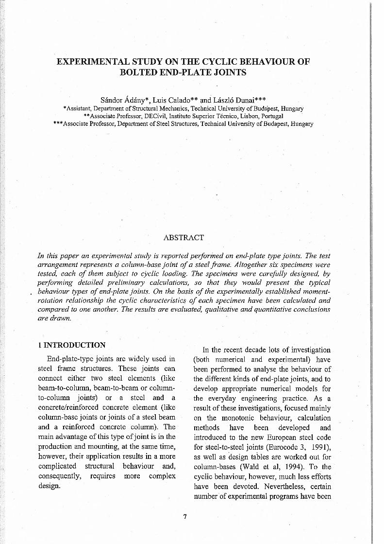
The test equiprnent is basically developedto test beam-to-column joints of steelfrarnes. The global arrangernent is illustratedin Figure 2. In addition, there is a lateralfrarne to rnake possible the lateral support ofthe specirnen, avoiding its lateral rnovernentor twisting. The whole testing prõcess isrnanaged by a personal computer, by meansof a data acquisition unit, which cornrnandsthe actuator and reads the data from theload celi and displacernent transducers.Another irnportant note that displacernentcontrol is used. (More informátion about thetest equiprnent •can be found in Ferreira1994 and Calado and Mele 1999.)
In. designing the test, the specirnencharacteristics are deterrnined in accordancewith the pararneters of the existing test setup, by considering the geornetricalproperties, the load capacíty of the actuatorand load ceil, as welJ as the displacernent
capacity of the inductive displacernenttransducers. lhe global arrangement ispresented in Figures 2 and 3, with the maingeornetrical dirnensions of the specirnens. inFigure 2. lhe arrangernent represents acolurnn base joint, with an H-shaped columnand a practically rigid base. The applicationof the base element is necessary to be ableto connect the colurnn to the base beam.The top part of the specirnen has the role toensure the restraint against lateral movementand twisting ofthe colurnn.
3.2 Prcliminary calculations
To be able to achieve the intendedphenomena of the specirnens prelirninarycalculations were done. The rnomentresistance of each joint was determined ontwo-dirnensional modeis as the minimum ofresistances belonging to the possible failuremodes.
four modes of failure were defined asillustrated in Figure 5. Mode 1 represents
1..rç
cross-section
270
+1 1*cD•
370
investigated joint
Figure 2 Global anangement with the main dimensions of the specirnens
9

the pure end-plate failure without failure ofbolts. Mode 4 corresponds to the pure boltfailure, without any failure of the end-plate.Mode 2 and 3 are two cases of combínedbolt and end-plate failure.
II
,q b
1_II..•t l+
plastíc hinge
I+4
Figure 4 Notations and assumed position of plasticbinges
There are two potential places whereplastic hinge (hinge-line) can be developed:
either at the bolts, or at the column flange.The assumed positions of the plastic hingesare presented in Figure 4;
The joint resistance belonging to thevarious failure modes can be expressed bythe following formulae, for Modes 1 to 4,respectively.
I1
Mode 2
:Mode 3 Mode 4
Figure 5 Possible failure modes of end-platejoints
Figure 3 Global arrangement of the test equipment
MRd,1 = Mep,Rd •2• [i +
MRd2 MepRd .í2+\
m+fl)
h’ n+fb,Rd• ,
m +n
MRd,3 = Mep,Rd + Fb,Rd . (h’ + m’)
MRd,4 = b
1
Mode 1
lo

Table 1 Moinent resistance calculation ofthejoints
t Plate res. Mode 1 Mode 2 Mode 3 Mode 4 Resistance
[mm] [kNm] [kNm] [kNm] [kNm] [kNm] [kNm]
10 1.35 18.1 33.0 55.5 85.2 18.1
12 1.944 27;() 36.3 56.3 85.2 27.0
16 3.456 51.4 44.5 58.3 85.2 44.5
20 5.4 86.4 55.2 60:7 85.2 55.2
• 22 6.534 108.6 61.5 62.1 $5.2 61.5
25 8.4375 148.8 72.2 64.3 $5.2 64.3
30 12.15 238.1 93.7 68.6 $5.2 68.8
40 21.6 540.0 152.0 79.2 85.2 79.2
50 33.75 1147.5 234.7 92.5 . 85.2 85.2
Tlie notations are as follow:
• Mep,Rcl denotes the plastic resistance of
the end-plate, calculated as:
Mep,Rcl = . fy
• Fb denotes the plastic resistance of
the bolts (two bolts), calculated as:
‘b,Rd = 2. Ab
. fyb
h’ and m’ can be calculated as:h’=h+t
, tm =rn—-—
2
• a, b, h, m, n, and t are geometricaldimensions of the joínt, presented inFigure 4,
• Ab is the sectional area ofone bolt,
• f, and Jb the yield stress of the base
material and bolt material, respectively.
The applied bolt is of grade 8.8, whilethe material is $235, which means that thecharacteristic value of the yield strength isequal to 640 MPa and. 235 MPa for the boltand the base material, respectively,according to the Eurocode 3 (1991).Generally, these characteristic values areadopted as the basis of further calculations.According to previous experiences,however, a higher value is considered forthe base material (270 MPa).
The column section is assumed to be aHEA 200 profile, or similar, the height of.which is h = 190 mm. For the bolt positionand extension of end-plate m =40 mm andn = 50 mm are applied. The thickness of theend-plate is treated as a parameter, varyingbetween 10 and 50 mm. The bolt diameteris 16 mm, which gives approximatelyA1, 200 mm2 for the arca ofone bolt.
The calculations are surnmarised inTable 1, showing the resistances of thevarious failure modes for the various platethickness values. The most probable failuremode is the one to which the minimalresistance belongs.
It can be seen from Table 1 that purebolt failure is not realistic to achieve sinceit occurs only in case of extrerncly thickend-plate. For that reason it was decided toeliminate the pure bolt failure from thestudy and, finally, three pieces of end-platethickness were chosen, according to failuremode 1, 2 and 3. These are:
• t = 12 mm, for Mode 1,• t 16 mm, forMode 2,• t = 25 mm, for Mode 3.
In addition, it was decided to study theeffect of bolt pre-tensioning. It can beassumed, however, that the resistance is notdependent on the pre-loading.
11

3.3 Tlie specimens
Altogether five specimens were designed.The main characteristics of the specirnensare sumrnarised in TaNe 2. An additionalnote that butt welds are applied between thecolumn and the end-plate in order tominimise the risk ofweld failure.
Moreover, there is a transducer, notpresented in Figure 6, to measure thehorizontal displacement of load applicationpoint. Since ali the test procedure iscontrolled by this displacement, it is referredas transducer TO.
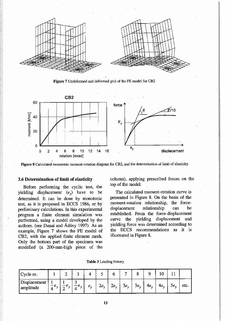
3.5 Loading history
3.4Displacement transducers
To measure the displacements inductivedisplacement transducers were used. Thenumber and the position of the transducerswere defined so as to get the possible mostinformation 011 the behaviour, consideringalso the place required for each transducer,which gives a limitation of their maximalnumber. Finally, altogether 13 transducerswerê used. Their arrangement from Ti toT12 is presented in Figure 6.
The loading history is defined inaccordance with (ECCS 1986) on the basisof the displacernent belonging to the limit ofelasticity (ex). In this study, however, twocycles were applied in the plastic rangeinstead of three as proposed in the (ECCS1986), because it was observed in previoustests (Calado and Lamas 1998) that the thirdcycle does not give additional inforn-iationrelatively to the previous two cycles. Thegeneral pattem ofin Table 3.
the loading is surnrnarised
Table 2 Specirnens main characteristics
Specimen Column End-plate Bolt tightening Anticipatedsection thickness behaviour
CB1 / CB1R HEA200 25 mm hand-tightened Mode 3
CB2 HEA200 16 mm hand-tightened Mode 2
CB3 welded 25 mm hand-tightened local buckling
CB4 HEA200 25 mm pre-tensioned Mode 3
CB5 HEA200 12 mm hand-tightened Mode 1
11 11
Figure 6 Anangement of displacement transducers
12
Ez 40
ca)EoE
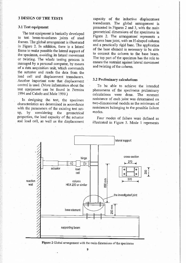
3.6 Determination of limit of elasticity
Before performing the cycic test, theyielding displacement (es) have to be
determined. It can be done by monotonictest, as ít is proposed in ECCS 1986, or bypreliminary calculations. In this experimentalprogram a finite element simulation wasperformed, using a model developed by theauthors. (see Dunai and Adány 1997) As anexample, Figure 7 shows the FE model ofCB2, with the applied finite element mesh.Only the bottom part of the specimen wasmodelled (a 200-mm-high piece of the
column), applying prescribed forces on thetop of the model.
The calculated moment-rotation curve ispresented in Figure 8. On the basis of themoment-rotation relationship, the forcedisplacement relationship can beestablished. From the force-displacementcurve the yielding displacement andyielding force was determined according tothe ECCS recommendations as it isillustrated in Figure 8.
Table 3 Loadmg history
Cyclenr. 1 2 3 4 5 6 7 8 9 10 11
Displacement 1 1 3—e —e eamplitude 4 2 4
e 2e 2e 3e 3e 4e 4e 5e etc.
Figure 7 Undeformed and deformed grid of the FE model for CB2
60CB2
force
F
o
Oo .2 4 6 8 10 12 14 16
rotation [mradJ
e
Figure $ Calculated monotonic moment-rotaüon diagram for CB2, and the detennination of limit of elasticity
displacement
13

4 RESULTS bolt plastification takes place in the bolt
4.1 Summary on the tests
At test CB1 (HEA 200 colurnn, 25-rnrn-thick end-plate, hand-tightened bolts, seeTable 2) the goveming phenornenon of thebehaviour is the elastic-plastic elongation ofthe bolts. The plastification, however, takesplace not in the bolt shank but in the boltand nut threads. Due to the deterioration ofthe nut thread, at the end of cycle 7 the. nutsof the tensioned bolts were “jurnped” fromthe bolt, which means joínt failure.
Since the specimen has not significantlydeteriorated during the test it was decidedto replace the bolts, applying more nuts(3 pcs), and repeating the test. The repeatedtest is referred as CB1R.
shank, which results in having more cyclesperforrned. At the end of cycle 13 one of thetensioned bolts broke which means thefailure ofthe joint.
In case of CB2 (HEA 200 column, 16-mm-thick end-plate, hand-tightened bolts,see Table 2 and Figure 10) specirnen thebehaviour follows Mode 2 (see Section 3.2).There is a strong interaction between twobasic phenomena: the base-platedeformation and the bolt elongation. Bothcomponents reach its plastic state, due toplate bending for the base-plate, and acornbined tensionlbending for the bolt. Atthe very end of cycle 16 the flange weld wasbroken, causing the failure ofthejoint.
In case of CB1R (see Table 2 and figure9) the behaviour is basically ídentical withthat ofCBl, following Mode 3 (see Section3.2). The rnost irnportant phenornenon is thebolt elongation, cornbined with certain endplate deformation. In this case, liowever, the
At CB3 test (welded column, 25-mm-thick end-plate, hand-tightened bolts, seeTable 2) the governing phenornenon is thebuckling of the colurnn flanges and web, asit can be seen in Figure 11. There is noconsiderable deformation of the bolt, and itrernains practically elastic during the wholetest. $irnilarly, the base-plate remains
Figure 9 CB iR test Figure 10 CB2 test
.14

practically flat, without plastic deformations.The large deformations are concentrated inthe bottom part of the column, approx.300 mm from the end-plate. It is to be notedthat the deformation pattem ofthe column isnot exactly symmetrical. It is interesting toobserve that there is a considerableshortening of the colurnn due to theflange/web buckling. (The maxirnumshortening is approx. 25 mm.) Afier the 27thcycle the test was decided to stop, since themajority of transducers reached theirrneasuring capacity, due to the largedeflections.
CR4 specirnen (HEA 200 column, 25-nirn-thick end-plate, pre-tensioned bolts, seeTable 2) is identical with CBÏ and CB1R,with the. only difference of bolt pretensioning. The beliaviour is similar to thatof CBIR, govemed by the bolt elongation.At cycle 11 one of the tensioned bolts isbroken, as it is presented in Figure 12. Thetest was not continued, because of thesignificant degradation of the joint loadhearing capacity.
For CB5 (HEA 200 colurnn, 12-rnrn-thick end-plate, hand-tightened bolts, seeTable 2) the governing phenomenon isdefinitely the base-plate defonriation (elasticand plastic). Nevertheless, the boltelongation lias also an influence, especiallyafter some plastic cycles. The behaviour isbetween Mode 1 and Mode 2 (see Section3.2). Nevertheless, the prying effèct wasclearly observed, especially at largerdisplacernents.
In cycle 11 a small crack occulTed in theend-plate beside the flange weld, along tliewhole width of the end-plate. At the end ofcycle 14 a similar crack developed at theopposite side of the column. Thedevelopment of the weld craóks resulted in adegradation of the resistance. At cycle 18 thejoint failed, caused by the complete failureofend-plate (see Figure 13).
C84
Figure 12 Failed bolt from CB4 test
Figure 11 CB3 test Figure 13 End-plate failure in CB5 test
15

4.2 Procedure for results evaluation Base rotation
Definition ofthejoint reference section
In order to be able to calculate thevarious mechanical characteristics of theinvestigated column-base joint, it isnecessary to define a section as jointreference section. This section is used tomeasure the forces/mornents which act onthe joint, and also the displacements of thissection give the joint displacernents.
The joint reference section is defined ata distance of twice the column sectiondepth (h,.= 2xcf) in order to be notdisturbed by the intensive deformation dueto local buckling. Note that hreí5 measuredfrom the top surface of the base-piate, whiled is the distance between the system linesof the flanges, as it is illustrated in Figure14. Since d is equal to 180 mm for ali thespecimens, the reference section is situated360 mm from the base-piate.
______
—
figure 14 Joint reference section
Forces, momentsThe joint forces/moments are defined as
the intemal forces/mornents of the referencesection.• The bending moment (M) can be
calculated as M F•Ah, where Ah is thevertical distance between the loadapplication point and the referencesection being equal to 530 mm for eachspecimen, while F is the applied force.
• The shear force (V) of the joint is equalto the force (F) applied to the specimenat the column top.
The rotation of the base can becalculated from the vertical displacementsofthe base eiement as:
0basc = (t9 — t8) d8_9,
where t8 and t9 are the displacementsmeasured by T8 and 19, and d9 is thedistance between the two transducers.
Rotation ofthe reference section
The rotation of the reference section canbe calculated from the measured verticaldisplacernents of the flanges, which arerecorded at two different leveis. The elasticcolumn deformations shouid also beconsidered. lhe rotation calculated fromT1-T2 and T3-T4:
01_2= 21
— 0base
O=
+034 0base
wheret. is the displacement measured by the ith transducer,
d12 and d34 are the horizontal distancesbetween transducer T1-T2 and T3-T4,
0bc,se is the base rotation as defined
above,
02 and 04 are the eiastic rotations
betweçn the reference section andmeasuring point for T1-T2 and T3-T4transducers, respectively.
• The rotation of the reference section isgenerally determined as tbe average vaiueofthose calculated from T1-T2 and T3-T4.
—O_ + O3_4
ref -
Sh,j between the base and base-plate
The relative displacement between thebase-plate and the base element can bederived from the data measured by Til andT12, considering the appropriate signs.
sl=t11 —t12
d=l8Omm
joïntreference section
EE
COC)
xC-’J
16
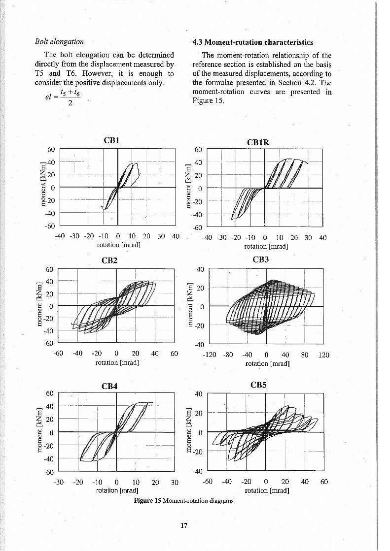
Bólt etongation ‘4.3 Moment-rotation characteristics
The bolt elongation can be deterrnineddirectly from the displacement measured byT5 and T6. However, it is enough toconsider the positive displacernents only.
ei =
2
60
r,40
20
E° 20
-40
-60
The rnornent-rotation relationship of thereference section is established 011 the basisof the rneasured displacernents, according tothe forrnulae presented in Section 4.2. Thernoment-rotation curves are presented inFigure 15.
60
40
20
E-20
-40
-60
E 20z
Eo-20
40
E 20
ci)
EoE -20
CB1RCBl
-40 -30 -20 -10 O 10 20rotation [mrad]
30 40
CB2
-40 -30 -20 -10 O 10 20 30 40rotation [mrad]
40CB3
60
40E20
60
40E20
-60 -40 -20 O 20rotation [mradJ
CB4
-4040 60 -120 -80 -40 O 40 80 120
rotation [mrad]
CB5
-30 -20 -10 O •10 20 30rotation [mrad]
-40
Figure 15 Mornent-rotation diagrams
-60 -40 -20 O 20 40 60rotation [mradJ
17

4.4 Base deformation 4.5 Slip between the base and base-plate
E 20
EoE -20
figure 17 Slip between the base and base-plate for CB2 and CB3
Figure 17 shows the slip-force diagramfor CB2 and CB3 specimens. (Here, theterrn “force” is the shear force.) It can beobserved that the developrnent of the slipbegins at the zero-force levei of each cycie,and very rapidly reaches its maximum value.This observation can be easily explaíned bytaking intô consideration that, at the zero-force levei, the contact area between thebase-plate and the base elernent is reduceddue to the residual deformations of baseplate.
Similar diagrams can be obtained for alithe cases where significant base-plate or boltdeformation is experienced (CB1, CB1R,CB2, CB4, and CB5). However, in case ofCB3, the effect of slip is almost negligible,since the base-plate and the bolts are notsubjected to plastic deformations.
40
A general observation is that thedeformations of the base element are notsigniftcant. They always remam in theelastic domam, with a maximum rotation ofappróx. 2-2.5 mrad, and a maximumhorizontal displacement of approx. 1 mm.Note, that the yielding rotation is between 4and• 12 rnrad, which means that the basedeforrnation has no signiflcant effect in theplastic range, but cannot be neglected in thevicinity of elastic range.
As an example, Figure 16 shows therotation of the base element for CB2 andCB3. Similar diagrarns are obtained for alitlie specimens, which clearly dernonstratesthat the base defoniiations are elastic,without having considerable effect on. cyclicjoint behavíour.
60
40E20
100
.50
) Oo
-50
-100
CB2 CB3
-3 -2 -1 O 1 2. 3rotation [mrad]
-3 -2 -1 O 1 2 3rotation [mradJ
-40
60
40
‘20
o
-40
-60-3 -2 -1 O
slip [mm]1 2 3 -0,6 -0,4 -0,2 O 0,2 0,4 0,6
slip [mm]
18
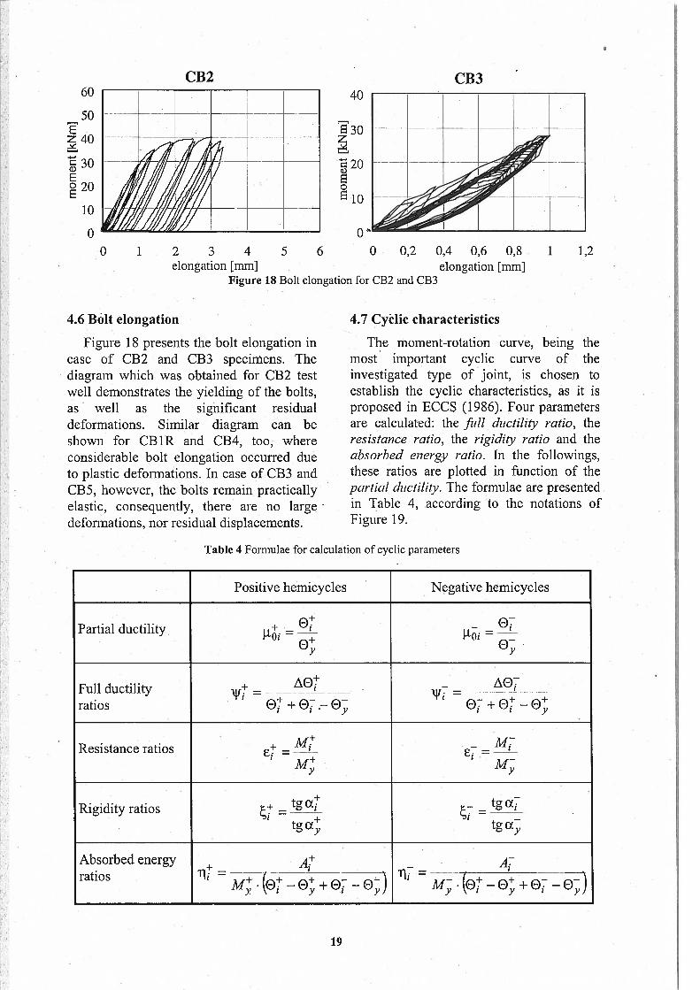
4.6 Bcilt elongation
Figure 18 presents the bolt elongation incase of CB2 and CB3 specirnens. lhediagram which was obtained for CB2 testwell dernonstrates the yielding of the bolts,as well as the significant residualdeformations. Similar diagram can beshown for CB1R and CB4, too, whereconsiderable bolt elongation occurred dueto plastic deformations. In case of CB3 andCB5, however, the bolts remam practicallyelastic, consequently, there are no largedeformations, nor residual displacements.
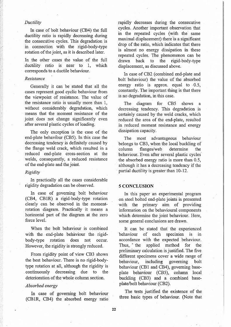
4.7 Cyèlic characteristics
lhe mornent-rotation curve, being thernost irnportant cyclic curve of theinvestigated type of joint, is chosen toestablish the cyclic characteristics, as it isproposed in ECCS (1986). Four pararnetersare calculated: the fui ductility ratio, theresistance ratio, the rigidity ratio and theabsorbed energy ratio. In the followings,these ratios are plotted in function of thepartial ducfllity. The forrnulae are presentedin Table 4, according to the notations ofFigure 19.
Table 4 Formulae for calculation of cyclic pararneters
. Positive hemicycles Negative hemicycles
Partial ductility =
Fuli ductility = =
ratios 07 + e — e; 1O + et
—
Resistance ratios = =
Rigidity ratios = =.
tg4 tgX
Absorbedenergy + g -
ratios 1i = li =
CB260
50
40
.30E
20
10
o
CB340
30
20so$ 10
OO 1 2 3 4 5 6 O 0,2 0,4 0,6 0,8 1 1,2
elongation [mm]Figure 18 Bolt elongation for CB2 and CB3
elongation [mm]
19

The calculated cyclic pararneters are failure ofthe bolts. Since the bolts are of
[
presented in Figure 20 for the positivehernicycles of the moment-rotationdiagrams. Note that CB1 test is notevaluated here, since, due to the early failureof the bolt and nut thread, the loadinghistory is too short.
Effect ofboltpre-tensioning
CB1R and CB4 specirnens are identical.However, in case of CBlR the bolts arehand-tightened, while in case of CB4 pretensioning is applied. Thus, the effect ofboltpre-tensioning can be analysed bycornparing the two cases.
The behaviours observed during the twotests are similar, as well as the calculatedcyclic parameters have similar tendencies,according to Figure 20. Thus, it can bestated that the bolt pre-tensioning has noirnportant effect on the cyclic behaviour inthe analysed cases.
Deformation capacity
An irnportant observation is that thedeforniation capacities of the various testedjoints strongly differ from each other.
If the governing behaviour is the boltbehaviour (Mode 3, see CB4 or CB1R),the maximal value of the partial ductilityis approx. equal to 4. In this case thefailure of the specirnen is caused by the
high-strength steel, the deformationcapacity of the bolts is lirnited, whichresults in a small deforrnation capacityofthejoint.
• In case of CB2 there is a stronginteraction between the bolt and endplate (Mode 2). The maxirnal value ofthe partial ductility is 6. In this case thefailure is caused by the crack occurred atthe flange to end-plate welds. It means,that although the behaviour itself isgoverned by the end-plate and boltdeforrnations, the failure is caused bythe weld crack, which lirnits thedeforrnation capacity ofthejoint.
• CB 5 corresponds to Mode 1, when thebehaviour is basically govemed by theend-plate deformations. lhe maximapartial ductility is slightly more than 4.It is to be noted, however, that thefailure is caused by the failure of theflange weld again, which reduced thedeformation capacity.If the governing behaviour is the colurnnftange/web buckling (CB3), the maxirnalpartial ductility is much more than anyof the other cases (more than. 20).Moreover, it should be rnentioned thatCB3 joint has not reached itsdeformation capacity during the test.(The test was finished because of therneasuring devices.)
e
M
Figure 19 Notation for the calculation of cyclic characteristics
20

CB 1 R
O 2 4 6 8 10 12 14 16 18 20partial ductílïty
CB2
1,5
1,0
0,5
0,0
1,5
1,0
0,5>
0,0
1,5
1,0
- 0,5
0,0
1,5
1,0
: 0,5>
0,0
1,5
1,0
0,5>I)
0,0
O 2 4 6 8 10 12 14 16 18 20partial ductility
CE3
partial duciility
CB4
pardal ductility
CB5
O 2 4 6 8 10 12 14 16 18 20
partial ductilíty
fuil ductility ratio resistance ratio rigídity ratio absorbedFigure 20 Cyclic characteristics for positive hemicycles of moment-rotation curves
21
Ductitity
In case of bolt behaviour (CB4) the fuilductility ratio is rapidly decreasing duringthe conseciitive cycles. This degradation isin connection with the rigid-body-typerotation ofthe joint, as it is described later.
In the other cases the value of the fuilductiiity ratio is near to 1, whichconesponds to a ductile behaviour.
Resistance
Generally it can be stated that ali thecases represent good cyclic behaviour fromthe viewpoint of resistance. The value ofthe resistance ratio is usually more than 1,without considerabiy degradation, whichmeans that the rnornent resistance of thejoint does not change significantly evenafter several plastic cycles of loading.
The only exception is the case of theend-plate behavibur ÇCB5). In this case thedecreasing tendency is definiteiy caused bythe flange weid crack, which resulted in areduced end-plate cross-sectíon at theweids, consequentiy, a reduced resistanceof the end-plate and the joint.
Rigidity
In practically ali the cases considerablerigidity degradation can be observed.
In case of goveming boit behaviour(CB4, CB1R) a rigid-body-type rotationcleariy can be observed in the momentrotation diagram. Practicaily it means ahorizontal part of the diagram at the zeroforce levei.
When the bolt behaviour is combinedwith the end-plate behâviour the rigidbody-type rotation does not occur.However, the rigidity is strongiy reduced.
from rigidity point of view CB3 showsthe best behaviour. There is no rigid-bodytype rotation at ali, although the rigidity iscontinuously decreasing due to thedeterioration of the whole coiurnn section.
Absorbed energy
In case of goveming boit behaviour(CB1R, CB4) the absorbed energy ratio
rapidly decreases during the consecutivecycles. Another irnportant observation thatin the repeated cycles (with the sarnemaxirnai díspiacernent) there Is a .significantdrop of.the ratio, which indicates that thereis alrnost no energy dissipation in theserepeated cycIés. The phenomenon can bedrawn back to the rigid-body-typedisplacernent, as discussed above.
In case of CB2 (cornbined end-plate andbolt behaviour) the value of the absorbedenergy ratio is approx. equal to 0.5,constantiy. The important thing is that thereis no degradation, in this case.
The diagram for CB5 shows adecreasing tendency. This degradation iscertainly caused by the weid cracks, whichreduced the area of the end-plate, resultedin reduced moment resistance and energydissipation capacity.
The rnost advantageous behaviourbelongs to CB3, when the local buckling ofcolumn flanges/web determine thebehaviour. Even after several plastic cyclesthe absorbed energy ratio is rnore than 0.5,although it has a decreasing tendency if thepartial ductility is greater than 10-12.
5 CONCLUSION
In this paper an experimental programon steel bolted end-plate joints is presented.with the primary aim of providinginformation on the behaviourai cornponentswhich determine the joint behaviour. Here,some general conciusions are drawn.
It can be stated that the experiencedbehaviour of each specinien is inaccordance with the expected behaviour.Thus, the applied rnethod for thepreiiminary calcuiation is justified. The fivedifferent specirnens cover a wide range ofbehaviour, including goveming boltbehaviour (CB1 and CB4), goveming basepiate behaviour (CB5), column localbuckiing (CB3) and a combined basepiate/bolt behaviour (CB2).
The tests justified the existence of thethree basic types of behaviour. (Note that
22

the concrete behaviour was not investigated REFERENCESin the present study.) However, theimportant effect of weld cracks is alsohighlighted. Whenever there is intensiveendp1ate deformation the failure is causedby the.cracks occurred at the flange to endplate welds. The cracks also influence thecyclic characteristics causing significantdegradation of the rnornent resistance andthe energy absorption capacity. Thus,although the end-plate behaviour wouldhave good cyclic characteristics (since it isdetermined by the steel material behaviour),the weld cracks can strongly modify thebehaviour.
The most advantageous behaviour isexperienced if the deformations areconcentrated iii the colunm section, forminga plastic hinge (CB3, governing columnbehaviour). In this case the behaviour isextremely ductile, with considerable energyabsorption capacity.. On the other hand,whenever there is signfficant boltelongation, the rigidity and energydissipation capacity of the jointconsiderably .decrease, due to the rigidbody-type rotation of the joint. In this casealso the deformation capacity is reduced, asa consequence of the limited elongationcapacity of the bolts.
The obtained results are applicable forthe verification and calibration of numericalmodeis. Detailed experimental data areprovided for various behaviour typescorresponding to the sarne joint topology. Itis important, however, to study the concretebehaviour, which cn be the topic of furtherinvestigations.
ACKNOWLEDGEMENTS
The research work has been conductedunder the financial support of the followingprojects: OTKA T02073 $ (HungarianNational Scientific Research Foundation),PBICT/P/CEG/23 5 9/95 (fundação para aCiência e a Tecnologica, in Portugal), andTEMPUS JEP 11236/96.
Ádány, S., Dunai, L. (1995): “Rigidity ofColunm-Base Connections under CombinedLoading”, International Colloquium onStability of Steel Structures, September 21-23, 1995, Budapest, Hungary, PrelirninaiyReport, Vol. II, pp. 3-lO.
Ádány, 5., Dunai, L. (1997): “Modelling ofsteel-to-concrete end-plate connectionsunder rnonotonic and cyclic loading”,Periodica Pàlitechnica ser. Civil Eng., Vol.41, No. 1, pp. 3-16, 1997.
Bailio, G., Calado, L. and Castiglioni, C. A.(1997): “Low Cycle Fatigue Behaviour ofStructural Steel Mernbers and Connections”,fatigue & fracture of EngineeringMateriais & Strttctures, Vol. 20, No. 8, pp.1129-1146.
Calado, L, Bemuzzi, C. and Castiglioni, C. A.(1998): “Structural Steel Components underLow-cycle Fatigue: Design Assisted byTesting”, Stmctural Engineering WorldCongress, SEWC, San Francisco.
Calado, L. and Lamas, A.Modelling and BehaviourColumn Connections”Conference on $teelSebastian, Spain.
Calado, L. and Mele, E. (1999): “ExperimentalResearch Program on Steel Beam-toColunm Connections “, Report ICIST, DTno 1/99, ISSN:087l-7869
Calado, L., Mele, E. and De Luca, A. (1999):“Cyclic Behaviour of Steel Semirigid Beamto-.Column Connections”, to be published inASCE.
Dunai, L. (1992): “Modelling of CyclicBehaviour of Steel Serni-Rigid Connection”,First State-of-the-Art Workshop on SemiRigid Behaviour of Civil Engineering.Structural Connections: COST Cl, Bmssels,Proceedings, pp. 394-405.
Dunai, L., Ádány, 5., Fukumoto, Y. (1995):“Mornent-Rotation Model of $teel-toConcrete End-plate Connections”,Proceedings of the Third IntemationalWorkshop on Connections in SteelStructures, 29 May - 1 June, 1995, Trento,Italy, Connections in $teei Structures IIL(ed R. Bjorhovde, Á. Colson and R.Zandonint2 pp. 269-277.
Dunai, L., Fukumoto, Y., Ohtani, Y. (1996):“Behaviour of $teel-to-Concrete Connections
(1998): “Sei’smicof Steel Beam-to
2’ WorldConstruction, San
23

under Combined Axial force and CyclicBending”, Journal of C’onstructional SteetResearch, Vol. 36, No. 2, pp. 12 1-147, 1996.
Dunai, L., Ádány, 5. (1997): “CyciicDeterioration Model for Steei-to-ConcreteJoints,” Second Intemationai Conference onthe Behaviour of $teei Structures in $eismicAreas (STE$SA ‘97), August 3-8, 1997,Kyoto, Japan, Froceedings, eU. f. liMazzolani, H Aktyarna), pp. 564-571.
ECC$ (1986): “Recornmended TestingProcedure for Assessing the Behaviour of$tructural $teel Elernents under CyclicLoads”, Technical Cornmittee 1, TWG 1.3,No. 45.
Eurocode 3 (1991): “Design Rules for $teelStructures, Part 1, General Rules and Rulesfor Buildings.”
Ferreira, J. (1994) “Charactersation of theBehaviour of Serni-Rigid $teel Connections”MSc Thesis, Instituto Superior Técnico,Lisbon, Portugal. (in portugztese)
Wald et ai., 1994: “Connection Design Tables toENV 1993-1-1 (Eurocode 3)”, eU: Wald, F.,Prague, 1994.
24