
Experimental Study of Bolted Connections Using Light Gauge ...
21
International Journal of Sciences: Basic and Applied Research (IJSBAR) ISSN 2307-4531 http://gssrr.org/index.php?journal=JournalOfBasicAndApplied Experimental Study of Bolted Connections Using Light Gauge Rectangular Hallow Section, Normal Concrete and Geopolymer concrete Infilled only at the Joints a* R. B. Kulkarni, and b S.P.Deshamukh a Dept. of Civil Engg., Gogte Institute of Technology, Belgaum – (Karnataka) b Dept of Civil Engg. Dr JJ Magadum College of Engineering Jaysingpur-(Maharastra) Abstract: Cold-formed structural members are being used more widely in routine structural design as the world steel industry moves from the production of hot-rolled section and plate to coil and strip, often with galvanised and/or painted coatings. Steel in this form is more easily delivered from the steel mill to the manufacturing plant where it is usually cold-rolled into open and closed section members. The present experimental study is on the effect of infilled Normal Concrete and Geopolymer concrete only at the joints in cold formed tubular sections and which may increase the load carrying capacity of the joints. In present study strength of the joint is increased by infilling different grades of concrete in the tubular specimens the joints with single number of bolts at the connection. This work presents number of experimental tests have been carried out on cold formed tubular tension members fastened with bolts, to calculate the failure capacity and increase in strength of the member and also to trace the entire load versus Strain/Elongation so that the behavior of the connection is examined and also MATLAB used for calculation of maximum loads for various thickness. Keywords: Light Gauge Steel Sections, Concretes, Strain/Elongation, Failure Pattern, MATLAB Software 1. Introduction The use of cold-formed steel members in building construction began in the 1850s in both the United States and Great Britain. In the 1920s and 1930s, acceptance of cold-formed steel as a construction material was still limited because there was no adequate design standard and limited information on material use in building codes. One of the first documented uses of cold-formed steel as a building material is the Virginia Baptist Hospital [1] , constructed around 1925 in Lynchburg, Virginia. The walls were load bearing masonry, but the floor system was framed with double back-to-back cold-formed steel lipped channels. ------------------------------------------------------------------------ * Corresponding author. E-mail address: Email: [email protected] 1
Transcript of Experimental Study of Bolted Connections Using Light Gauge ...
International Journal of Sciences: Basic and Applied Research (IJSBAR)
ISSN 2307-4531
http://gssrr.org/index.php?journal=JournalOfBasicAndApplied
Experimental Study of Bolted Connections Using Light Gauge Rectangular Hallow Section, Normal Concrete and Geopolymer
concrete Infilled only at the Joints a*R. B. Kulkarni, and bS.P.Deshamukh
a Dept. of Civil Engg., Gogte Institute of Technology, Belgaum – (Karnataka)
bDept of Civil Engg. Dr JJ Magadum College of Engineering Jaysingpur-(Maharastra)
Abstract:
Cold-formed structural members are being used more widely in routine structural design as the world steel industry moves from the production of hot-rolled section and plate to coil and strip, often with galvanised and/or painted coatings. Steel in this form is more easily delivered from the steel mill to the manufacturing plant where it is usually cold-rolled into open and closed section members. The present experimental study is on the effect of infilled Normal Concrete and Geopolymer concrete only at the joints in cold formed tubular sections and which may increase the load carrying capacity of the joints. In present study strength of the joint is increased by infilling different grades of concrete in the tubular specimens the joints with single number of bolts at the connection. This work presents number of experimental tests have been carried out on cold formed tubular tension members fastened with bolts, to calculate the failure capacity and increase in strength of the member and also to trace the entire load versus Strain/Elongation so that the behavior of the connection is examined and also MATLAB used for calculation of maximum loads for various thickness.
Keywords: Light Gauge Steel Sections, Concretes, Strain/Elongation, Failure Pattern, MATLAB Software
1. Introduction
The use of cold-formed steel members in building construction began in the 1850s in both the United States and Great Britain. In the 1920s and 1930s, acceptance of cold-formed steel as a construction material was still limited because there was no adequate design standard and limited information on material use in building codes. One of the first documented uses of cold-formed steel as a building material is the Virginia Baptist Hospital [1], constructed around 1925 in Lynchburg, Virginia. The walls were load bearing masonry, but the floor system was framed with double back-to-back cold-formed steel lipped channels.
------------------------------------------------------------------------ * Corresponding author. E-mail address: Email: [email protected]
1
International Journal of Sciences: Basic and Applied Research (IJSBAR) (2010) Volume 1, No 1, pp 1-21
According to Chuck Greene, P.E of Nolen Frisa Associates [2], the joists were adequate to carry the initial loads and spans, based on current analysis techniques. Greene engineered a recent renovation to the structure and said that for the most part, the joists are still performing well. A site observation during this renovation confirmed that "these joists from the 'roaring twenties' are still supporting loads, over 80 years later!" In the 1940s, Lustron Homes built and sold almost 2500 steel-framed homes, with the framing, finishes, cabinets and furniture made from cold-formed steel.
Cold-Formed Steel (CFS) is the common term for products made by rolling or pressing thin gauges of sheet steel into goods. Cold-formed steel goods are created by the working of sheet steel using stamping, rolling, or presses to deform the sheet into a usable product. Cold worked steel products are commonly used in all areas of manufacturing of durable goods like appliances or automobiles but the phrase cold form steel is most prevalently used to described construction materials. The use of cold-formed steel construction materials has become more and more popular since its initial introduction of codified standards in 1946. In the construction industry both structural and non-structural elements are created from thin gauges of sheet steel. These building materials encompass columns, beams, joists, studs, floor decking, built-up sections and other components. Cold-formed steel construction materials differ from other steel construction materials known as hot-rolled steel. The manufacturing of cold-formed steel products occurs at room temperature using rolling or pressing. The strength of elements used for design is usually governed by buckling. The construction practices are more similar to timber framing using screws to assemble stud frames.
Cold-formed steel (CFS) members have been used in buildings, bridges, storage racks, grain bins, car bodies, railway coaches, highway products, transmission towers, transmission poles, drainage facilities, various types of equipment and others. These types of sections are cold-formed from steel sheet, strip, plate, or flat bar in roll forming machines, by press brake (machine press) or bending operations. The material thicknesses for such thin-walled steel members usually range from 0.0147 in. (0.373 mm) to about ¼ in. (6.35 mm). Steel plates and bars as thick as 1 in. (25.4 mm) can also be cold-formed successfully into structural shapes.
Tension Member
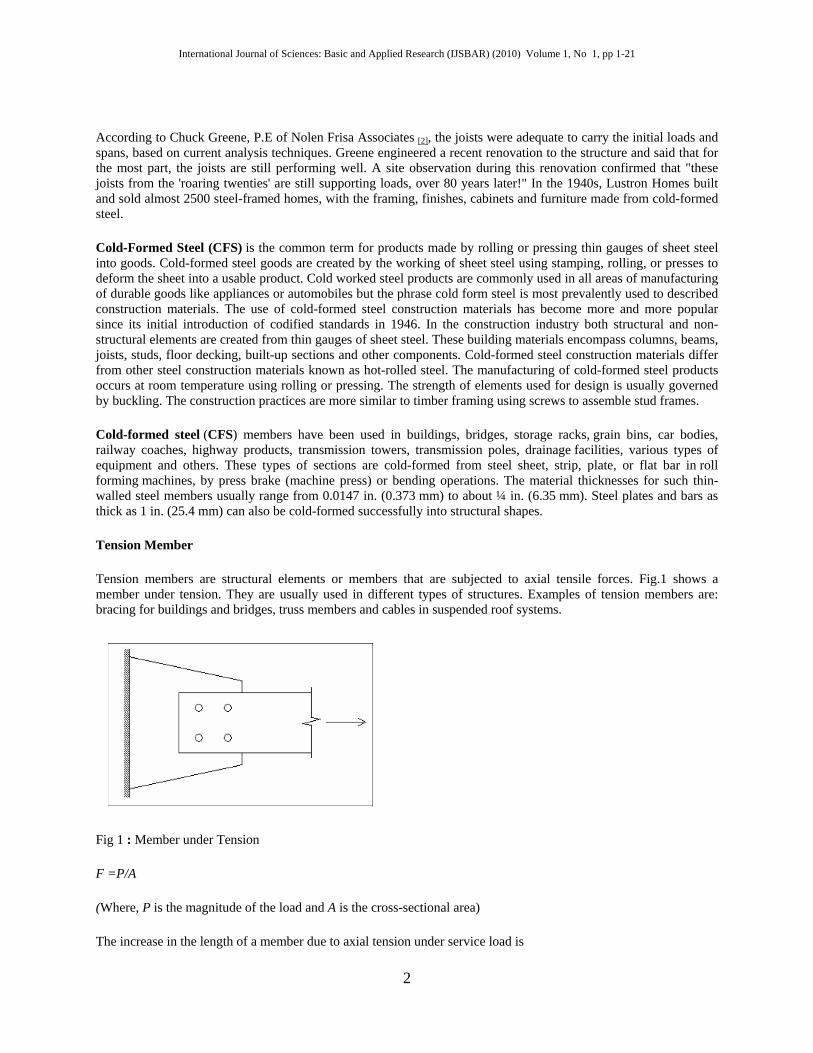
Tension members are structural elements or members that are subjected to axial tensile forces. Fig.1 shows a member under tension. They are usually used in different types of structures. Examples of tension members are: bracing for buildings and bridges, truss members and cables in suspended roof systems.
Fig 1 : Member under Tension
F =P/A
(Where, P is the magnitude of the load and A is the cross-sectional area)
The increase in the length of a member due to axial tension under service load is
2
International Journal of Sciences: Basic and Applied Research (IJSBAR) (2010) Volume 1, No 1, pp 1-21
Δ=PL / (E.Ag)
Where,
Δ is the axial elongation of the member (mm),P is the axial tensile force (un-factored) in the member (N),L is the length of the member (mm) and E is the modulus of elasticity of steel=2.0x10 MPa.
Note : that displacement is a serviceability limit state criterion and hence is checked under service loads and not under factored loads.
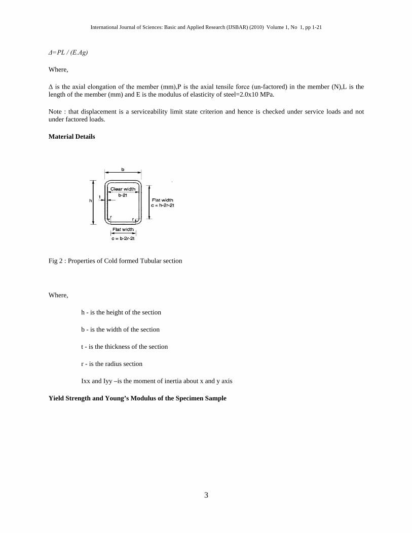
Material Details
Fig 2 : Properties of Cold formed Tubular section
Where,
h - is the height of the section
b - is the width of the section
t - is the thickness of the section
r - is the radius section
Ixx and Iyy –is the moment of inertia about x and y axis
Yield Strength and Young’s Modulus of the Specimen Sample
3
International Journal of Sciences: Basic and Applied Research (IJSBAR) (2010) Volume 1, No 1, pp 1-21
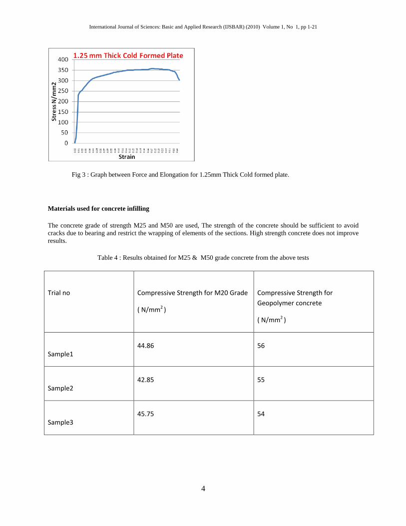
Fig 3 : Graph between Force and Elongation for 1.25mm Thick Cold formed plate.
Materials used for concrete infilling
The concrete grade of strength M25 and M50 are used, The strength of the concrete should be sufficient to avoid cracks due to bearing and restrict the wrapping of elements of the sections. High strength concrete does not improve results.
Table 4 : Results obtained for M25 & M50 grade concrete from the above tests
Trial no
Compressive Strength for M20 Grade
( N/mm2 )
Compressive Strength for Geopolymer concrete
( N/mm2 )
Sample1 44.86 56
Sample2 42.85 55
Sample3 45.75 54
4
International Journal of Sciences: Basic and Applied Research (IJSBAR) (2010) Volume 1, No 1, pp 1-21
Connections
1. Connections Designed more conservatively than members because they are more complex to analyse and discrepancy between analysis and design is large 2. In case of overloading, failure in member is preferred to failure in connection 3. Connections account for more than half the cost of structural steel work 4. Connection design has influence over member design 5. Similar to members, connections are also classified as idealised types effected through rivets, bolts or weld
Connections are normally made either by bolting or welding. Bolting is common in field connections, since it is simple and economical to make. Bolting is also regarded as being more appropriate in field connections from considerations of safety. However, welded connections, which are easier to make and are more efficient, are usually resorted to in shop fabrications.
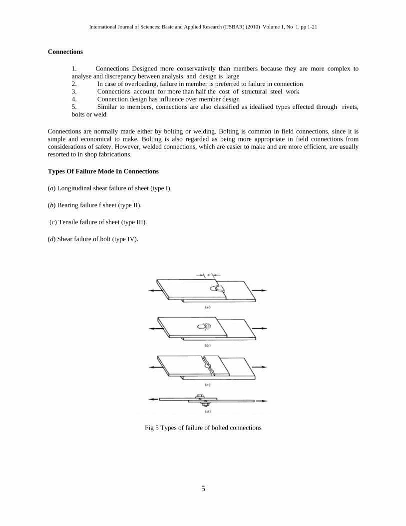
Types Of Failure Mode In Connections
(a) Longitudinal shear failure of sheet (type I).
(b) Bearing failure f sheet (type II).
(c) Tensile failure of sheet (type III).
(d) Shear failure of bolt (type IV).
Fig 5 Types of failure of bolted connections
5
International Journal of Sciences: Basic and Applied Research (IJSBAR) (2010) Volume 1, No 1, pp 1-21
Experimental Tests
The tension test is used to ascertain several mechanical properties of materials that are important in design. The results of tensile tests are used in selecting materials for engineering applications. Tensile properties are often measured during development of new materials and processes, so that different materials and processes can be compared. Finally, tensile properties are often used to predict the behavior of a material under different forms of loading.
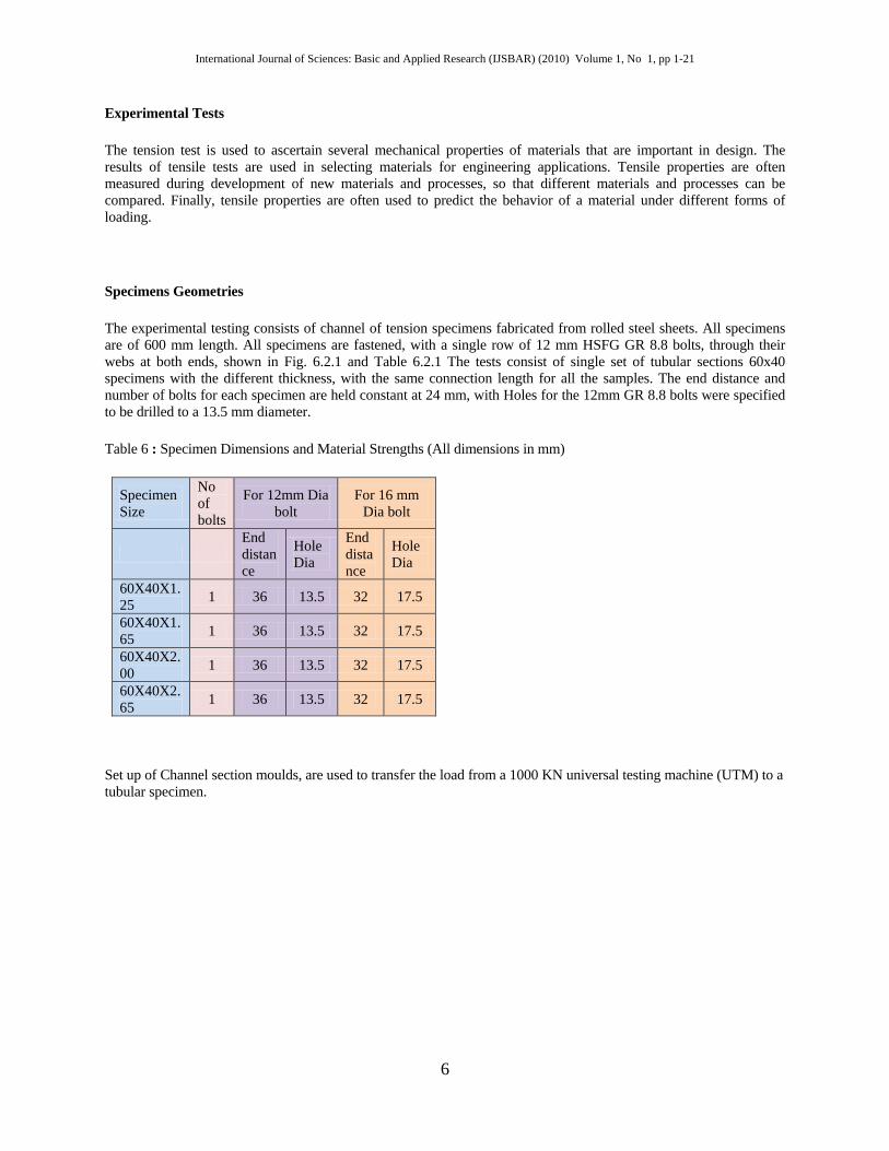
Specimens Geometries
The experimental testing consists of channel of tension specimens fabricated from rolled steel sheets. All specimens are of 600 mm length. All specimens are fastened, with a single row of 12 mm HSFG GR 8.8 bolts, through their webs at both ends, shown in Fig. 6.2.1 and Table 6.2.1 The tests consist of single set of tubular sections 60x40 specimens with the different thickness, with the same connection length for all the samples. The end distance and number of bolts for each specimen are held constant at 24 mm, with Holes for the 12mm GR 8.8 bolts were specified to be drilled to a 13.5 mm diameter.
Table 6 : Specimen Dimensions and Material Strengths (All dimensions in mm)
Specimen Size
No of bolts
For 12mm Dia bolt
For 16 mm Dia bolt
End distance
Hole Dia
End distance
Hole Dia
60X40X1.25 1 36 13.5 32 17.5
60X40X1.65 1 36 13.5 32 17.5
60X40X2.00 1 36 13.5 32 17.5
60X40X2.65 1 36 13.5 32 17.5
Set up of Channel section moulds, are used to transfer the load from a 1000 KN universal testing machine (UTM) to a tubular specimen.
6
International Journal of Sciences: Basic and Applied Research (IJSBAR) (2010) Volume 1, No 1, pp 1-21
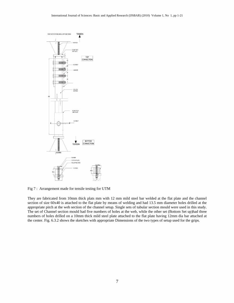
Fig 7 : Arrangement made for tensile testing for UTM
They are fabricated from 10mm thick plats mm with 12 mm mild steel bar welded at the flat plate and the channel section of size 60x40 is attached to the flat plate by means of welding and had 13.5 mm diameter holes drilled at the appropriate pitch at the web section of the channel setup. Single sets of tubular section mould were used in this study. The set of Channel section mould had five numbers of holes at the web, while the other set (Bottom Set up)had three numbers of holes drilled on a 10mm thick mild steel plate attached to the flat plate having 12mm dia bar attached at the center. Fig. 6.3.2 shows the sketches with appropriate Dimensions of the two types of setup used for the grips.
7
International Journal of Sciences: Basic and Applied Research (IJSBAR) (2010) Volume 1, No 1, pp 1-21
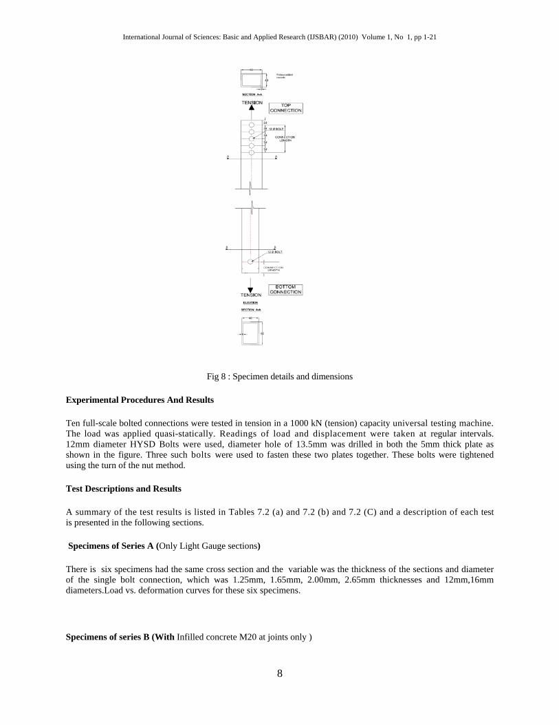
Fig 8 : Specimen details and dimensions
Experimental Procedures And Results
Ten full-scale bolted connections were tested in tension in a 1000 kN (tension) capacity universal testing machine. The load was applied quasi-statically. Readings of load and displacement were taken at regular intervals. 12mm diameter HYSD Bolts were used, diameter hole of 13.5mm was drilled in both the 5mm thick plate as shown in the figure. Three such bolts were used to fasten these two plates together. These bolts were tightened using the turn of the nut method.
Test Descriptions and Results
A summary of the test results is listed in Tables 7.2 (a) and 7.2 (b) and 7.2 (C) and a description of each test is presented in the following sections.
Specimens of Series A (Only Light Gauge sections)
There is six specimens had the same cross section and the variable was the thickness of the sections and diameter of the single bolt connection, which was 1.25mm, 1.65mm, 2.00mm, 2.65mm thicknesses and 12mm,16mm diameters.Load vs. deformation curves for these six specimens.
Specimens of series B (With Infilled concrete M20 at joints only )
8
International Journal of Sciences: Basic and Applied Research (IJSBAR) (2010) Volume 1, No 1, pp 1-21
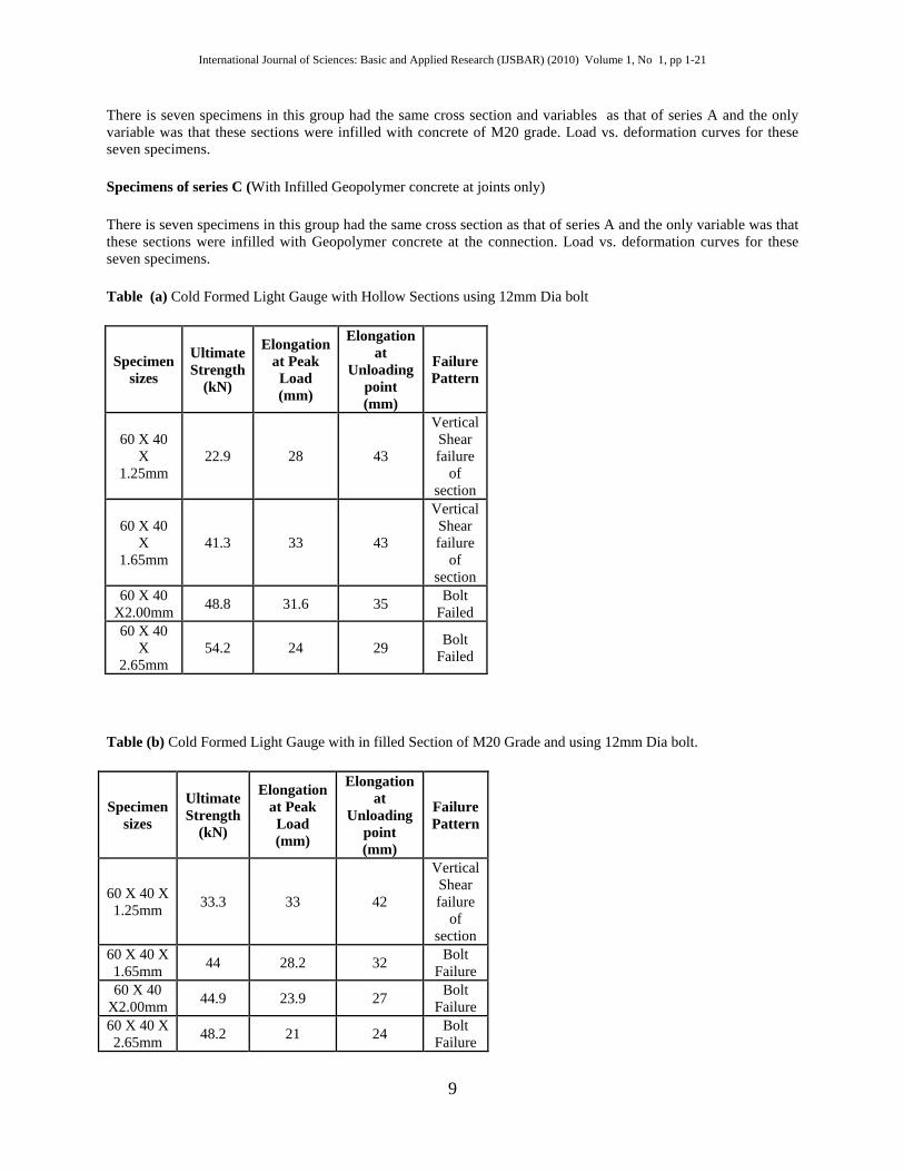
There is seven specimens in this group had the same cross section and variables as that of series A and the only variable was that these sections were infilled with concrete of M20 grade. Load vs. deformation curves for these seven specimens.
Specimens of series C (With Infilled Geopolymer concrete at joints only)
There is seven specimens in this group had the same cross section as that of series A and the only variable was that these sections were infilled with Geopolymer concrete at the connection. Load vs. deformation curves for these seven specimens.
Table (a) Cold Formed Light Gauge with Hollow Sections using 12mm Dia bolt
Specimen sizes
Ultimate Strength
(kN)
Elongation at Peak Load (mm)
Elongation at
Unloading point (mm)
Failure Pattern
60 X 40 X
1.25mm 22.9 28 43
Vertical Shear failure
of section
60 X 40 X
1.65mm 41.3 33 43
Vertical Shear failure
of section
60 X 40 X2.00mm 48.8 31.6 35 Bolt
Failed 60 X 40
X 2.65mm
54.2 24 29 Bolt Failed
Table (b) Cold Formed Light Gauge with in filled Section of M20 Grade and using 12mm Dia bolt.
Specimen sizes
Ultimate Strength
(kN)
Elongation at Peak Load (mm)
Elongation at
Unloading point (mm)
Failure Pattern
60 X 40 X 1.25mm 33.3 33 42
Vertical Shear failure
of section
60 X 40 X 1.65mm 44 28.2 32 Bolt
Failure 60 X 40
X2.00mm 44.9 23.9 27 Bolt Failure
60 X 40 X 2.65mm 48.2 21 24 Bolt
Failure
9

International Journal of Sciences: Basic and Applied Research (IJSBAR) (2010) Volume 1, No 1, pp 1-21
Table (c) Cold Formed Light Gauge with in filled Sections of Geopolymer concrete and using 12mm Dia bolt.
Specimen sizes
Ultimate Strength
(kN)
Elongation at Peak Load (mm)
Elongation at
Unloading point (mm)
Failure Pattern
60 X 40 X 1.25mm 36 29.7 42
Vertical Shear
failure of section
60 X 40 X 1.65mm 44 28 32 Bolt
Failure
60 X 40 X2.00mm 42.8 42.8 21 Bolt
Failure
60 X 40 X 2.65mm 50.1 50.1 27 Bolt
Failure
Table 7.2 (d) Cold Formed Light Gauge with Hollow Sections using 16mm Dia bolt
Specimen sizes
Ultimate Strength
(kN)
Elongation at Peak Load (mm)
Elongation at
Unloading point (mm)
Failure Pattern
60 X 40 X
2.00mm 62.7 32 44
Vertical Shear failure
of section
60 X 40 X
2.65mm 82.7 29 44
Vertical Shear failure
of section
10
International Journal of Sciences: Basic and Applied Research (IJSBAR) (2010) Volume 1, No 1, pp 1-21
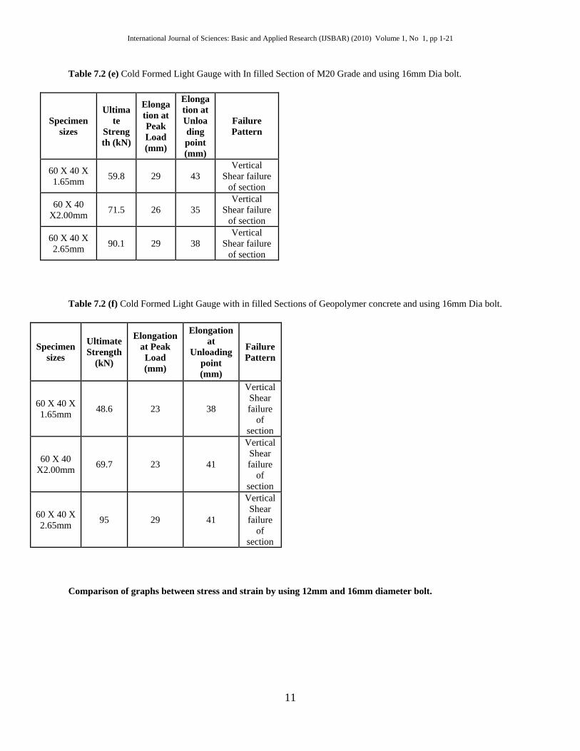
Table 7.2 (e) Cold Formed Light Gauge with In filled Section of M20 Grade and using 16mm Dia bolt.
Specimen sizes
Ultimate
Strength (kN)
Elongation at Peak Load (mm)
Elongation at Unloading point (mm)
Failure Pattern
60 X 40 X 1.65mm 59.8 29 43
Vertical Shear failure
of section
60 X 40 X2.00mm 71.5 26 35
Vertical Shear failure
of section
60 X 40 X 2.65mm 90.1 29 38
Vertical Shear failure
of section
Table 7.2 (f) Cold Formed Light Gauge with in filled Sections of Geopolymer concrete and using 16mm Dia bolt.
Specimen sizes
Ultimate Strength
(kN)
Elongation at Peak Load (mm)
Elongation at
Unloading point (mm)
Failure Pattern
60 X 40 X 1.65mm 48.6 23 38
Vertical Shear failure
of section
60 X 40 X2.00mm 69.7 23 41
Vertical Shear failure
of section
60 X 40 X 2.65mm 95 29 41
Vertical Shear failure
of section
Comparison of graphs between stress and strain by using 12mm and 16mm diameter bolt.
11
International Journal of Sciences: Basic and Applied Research (IJSBAR) (2010) Volume 1, No 1, pp 1-21
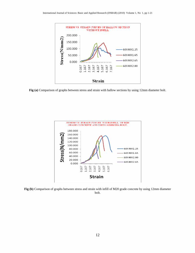
Fig (a) Comparison of graphs between stress and strain with hallow sections by using 12mm diameter bolt.
Fig (b) Comparison of graphs between stress and strain with infill of M20 grade concrete by using 12mm diameter bolt.
12

International Journal of Sciences: Basic and Applied Research (IJSBAR) (2010) Volume 1, No 1, pp 1-21
Fig (c) Comparison of graphs between stress and strain with infill of geopolymer concrete by using 12mm diameter bolt.
Fig (d) Comparison of graphs between stress and strain with hallow sections by using 16mm diameter bolt.
13
International Journal of Sciences: Basic and Applied Research (IJSBAR) (2010) Volume 1, No 1, pp 1-21
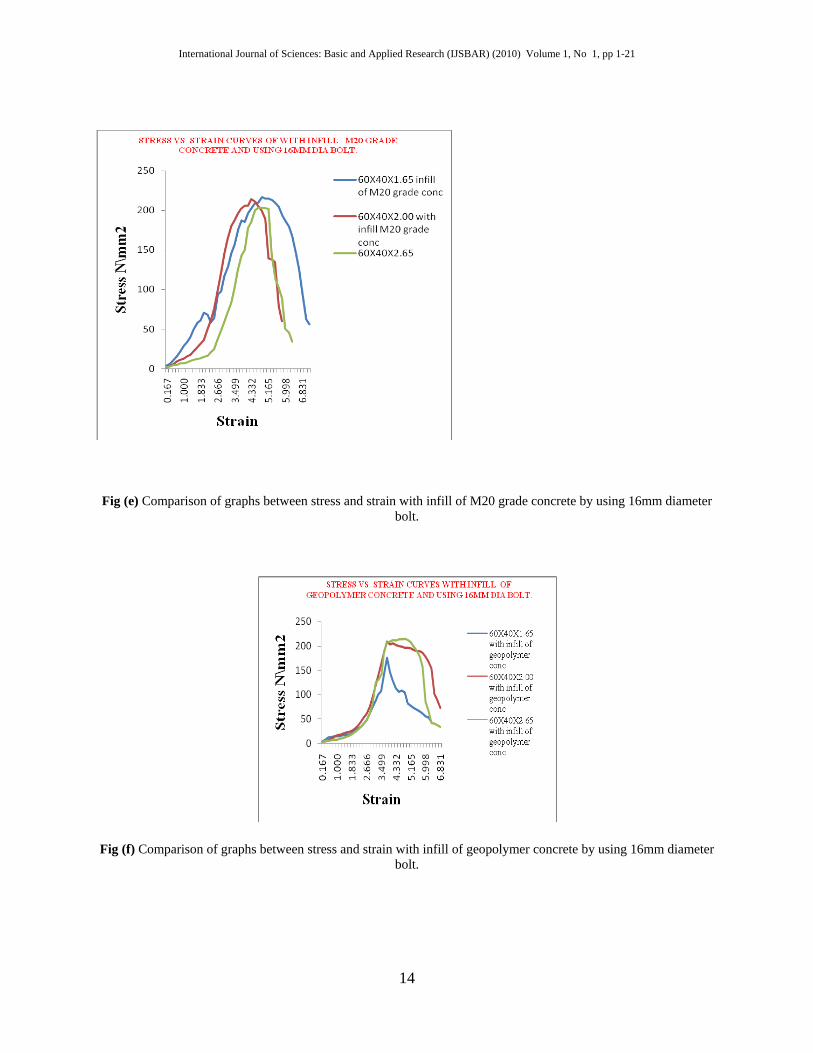
Fig (e) Comparison of graphs between stress and strain with infill of M20 grade concrete by using 16mm diameter bolt.
Fig (f) Comparison of graphs between stress and strain with infill of geopolymer concrete by using 16mm diameter bolt.
14
International Journal of Sciences: Basic and Applied Research (IJSBAR) (2010) Volume 1, No 1, pp 1-21
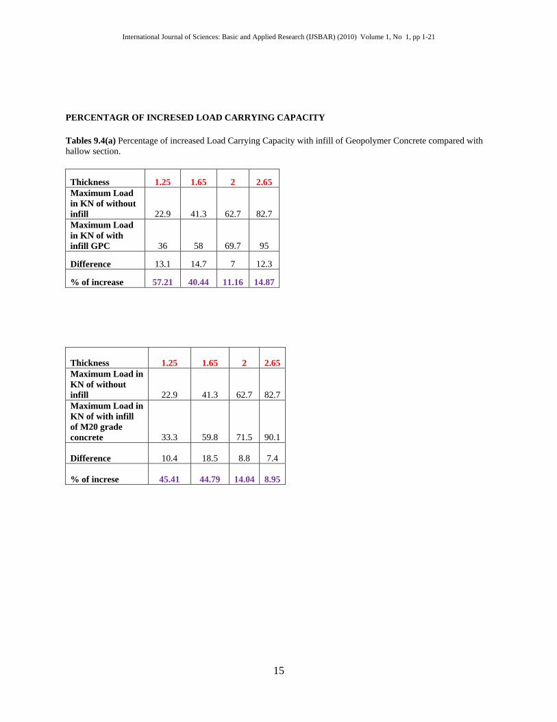
PERCENTAGR OF INCRESED LOAD CARRYING CAPACITY
Tables 9.4(a) Percentage of increased Load Carrying Capacity with infill of Geopolymer Concrete compared with hallow section.
Thickness 1.25 1.65 2 2.65 Maximum Load in KN of without infill 22.9 41.3 62.7 82.7 Maximum Load in KN of with infill GPC 36 58 69.7 95
Difference 13.1 14.7 7 12.3
% of increase 57.21 40.44 11.16 14.87
Thickness 1.25 1.65 2 2.65 Maximum Load in KN of without infill 22.9 41.3 62.7 82.7 Maximum Load in KN of with infill of M20 grade concrete 33.3 59.8 71.5 90.1
Difference 10.4 18.5 8.8 7.4
% of increse 45.41 44.79 14.04 8.95
15
International Journal of Sciences: Basic and Applied Research (IJSBAR) (2010) Volume 1, No 1, pp 1-21
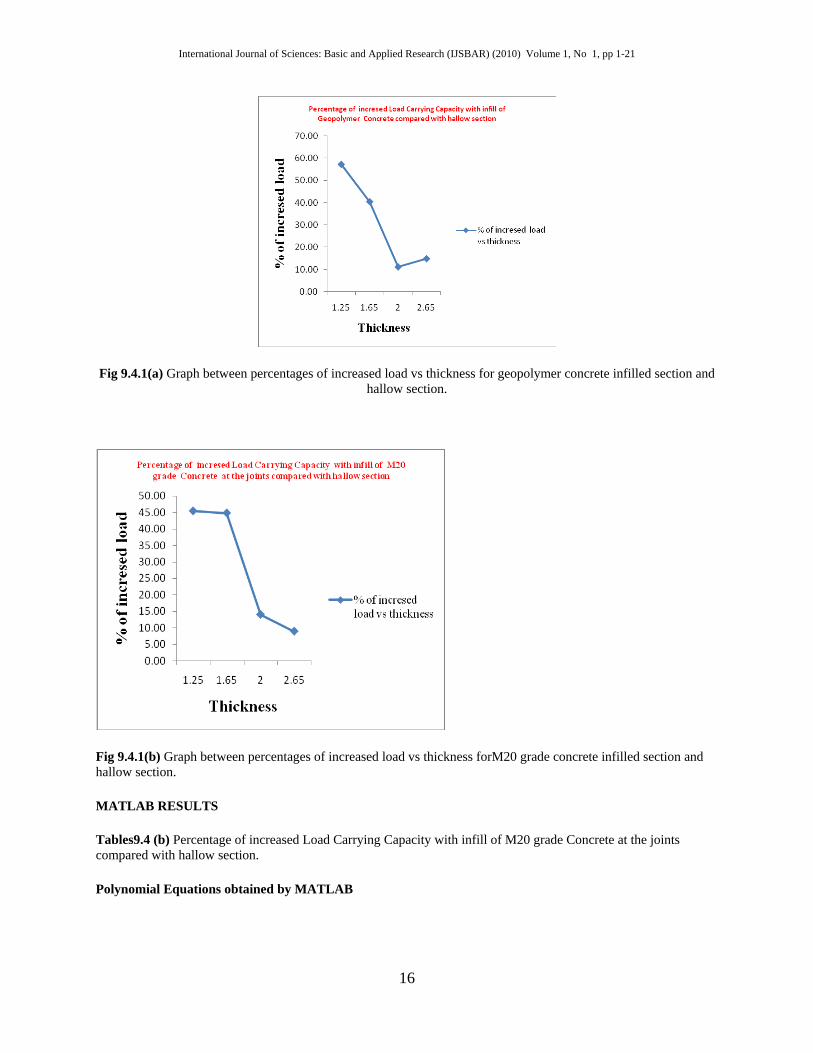
Fig 9.4.1(a) Graph between percentages of increased load vs thickness for geopolymer concrete infilled section and hallow section.
Fig 9.4.1(b) Graph between percentages of increased load vs thickness forM20 grade concrete infilled section and hallow section.
MATLAB RESULTS
Tables9.4 (b) Percentage of increased Load Carrying Capacity with infill of M20 grade Concrete at the joints compared with hallow section.
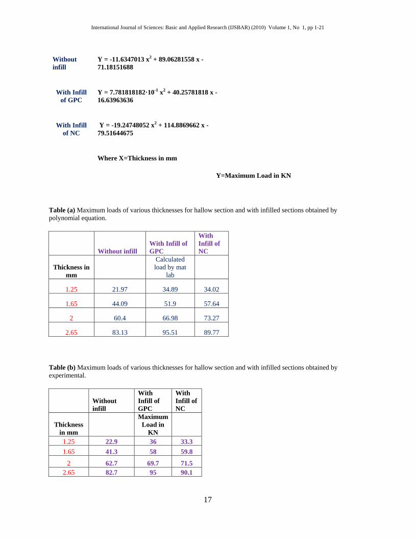
Polynomial Equations obtained by MATLAB
16
International Journal of Sciences: Basic and Applied Research (IJSBAR) (2010) Volume 1, No 1, pp 1-21
Without infill
Y = -11.6347013 x2 + 89.06281558 x - 71.18151688
With Infill of GPC
Y = 7.781818182·10-1 x2 + 40.25781818 x - 16.63963636
With Infill of NC
Y = -19.24748052 x2 + 114.8869662 x - 79.51644675
Where X=Thickness in mm
Y=Maximum Load in KN
Table (a) Maximum loads of various thicknesses for hallow section and with infilled sections obtained by polynomial equation.
Without infill With Infill of GPC
With Infill of NC
Thickness in mm
Calculated load by mat
lab
1.25 21.97 34.89 34.02
1.65 44.09 51.9 57.64
2 60.4 66.98 73.27
2.65 83.13 95.51 89.77
Table (b) Maximum loads of various thicknesses for hallow section and with infilled sections obtained by experimental.
Without infill
With Infill of GPC
With Infill of NC
Thickness in mm
Maximum Load in
KN 1.25 22.9 36 33.3 1.65 41.3 58 59.8
2 62.7 69.7 71.5 2.65 82.7 95 90.1
17
International Journal of Sciences: Basic and Applied Research (IJSBAR) (2010) Volume 1, No 1, pp 1-21
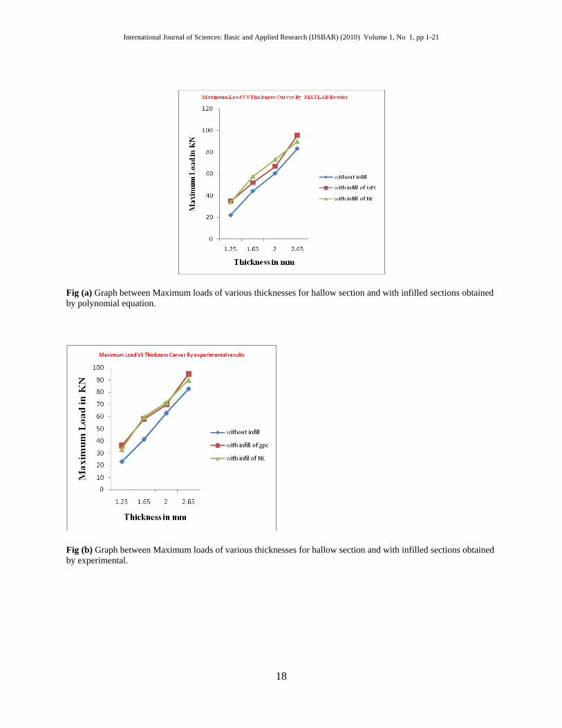
Fig (a) Graph between Maximum loads of various thicknesses for hallow section and with infilled sections obtained by polynomial equation.
Fig (b) Graph between Maximum loads of various thicknesses for hallow section and with infilled sections obtained by experimental.
18
International Journal of Sciences: Basic and Applied Research (IJSBAR) (2010) Volume 1, No 1, pp 1-21
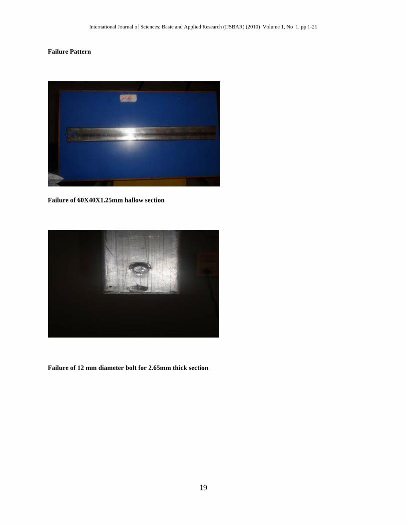
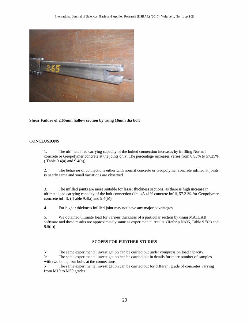
Failure Pattern
Failure of 60X40X1.25mm hallow section
Failure of 12 mm diameter bolt for 2.65mm thick section
19
International Journal of Sciences: Basic and Applied Research (IJSBAR) (2010) Volume 1, No 1, pp 1-21
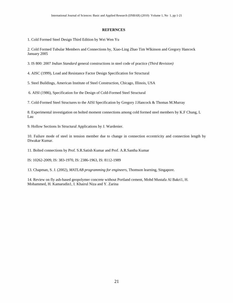
Shear Failure of 2.65mm hallow section by using 16mm dia bolt
CONCLUSIONS
1. The ultimate load carrying capacity of the bolted connection increases by infilling Normal concrete or Geopolymer concrete at the joints only. The percentage increases varies from 8.95% to 57.25%. ( Table 9.4(a) and 9.4(b)) 2. The behavior of connections either with normal concrete or Geopolymer concrete infilled at joints is nearly same and small variations are observed. 3. The infilled joints are more suitable for lesser thickness sections, as there is high increase in ultimate load carrying capacity of the bolt connection (i.e. 45.41% concrete infill, 57.21% for Geopolymer concrete infill). ( Table 9.4(a) and 9.4(b)) 4. For higher thickness infilled joint may not have any major advantages. 5. We obtained ultimate load for various thickness of a particular section by using MATLAB software and these results are approximately same as experimental results. (Refer p.No96, Table 9.5(a) and 9.5(b))
SCOPES FOR FURTHER STUDIES
The same experimental investigation can be carried out under compression load capacity. The same experimental investigation can be carried out in details for more number of samples with two bolts, four bolts at the connections. The same experimental investigation can be carried out for different grade of concretes varying from M10 to M50 grades.
20
International Journal of Sciences: Basic and Applied Research (IJSBAR) (2010) Volume 1, No 1, pp 1-21
REFERNCES
1. Cold Formed Steel Design Third Edition by Wei Wen Yu
2. Cold Formed Tubular Members and Connections by, Xiao-Ling Zhao Tim Wlkinson and Gregory Hancock January 2005
3. IS 800: 2007 Indian Standard general constructions in steel code of practice (Third Revision)
4. AISC (1999), Load and Resistance Factor Design Specification for Structural
5. Steel Buildings, American Institute of Steel Construction, Chicago, Illinois, USA
6. AISI (1986), Specification for the Design of Cold-Formed Steel Structural
7. Cold-Formed Steel Structures to the AISI Specification by Gregory J.Hancock & Thomas M.Murray
8. Experimental investigation on bolted moment connections among cold formed steel members by K.F Chung, L Lau
9. Hollow Sections In Structural Applications by J. Wardenier.
10. Failure mode of steel in tension member due to change in connection eccentricity and connection length by Diwakar Kumar.
11. Bolted connections by Prof. S.R.Satish Kumar and Prof. A.R.Santha Kumar
IS: 10262-2009, IS: 383-1970, IS: 2386-1963, IS: 8112-1989
13. Chapman, S. J. (2002), MATLAB programming for engineers, Thomson learning, Singapore.
14. Review on fly ash-based geopolymer concrete without Portland cement, Mohd Mustafa Al Bakri1, H. Mohammed, H. Kamarudin1, I. Khairul Niza and Y. Zarina
21


![Bolted Connections[1]](https://static.fdocuments.us/doc/165x107/54e7f8c84a7959704f8b46b8/bolted-connections1.jpg)
![[SATO] Bolted Flange Plate Moment Connections](https://static.fdocuments.us/doc/165x107/577cd67d1a28ab9e789c841c/sato-bolted-flange-plate-moment-connections.jpg)


