Boiler Room Guide - K F Industrials · Boiler Room Guide ... personnel in understanding the...
88
Boiler Room Guide
Transcript of Boiler Room Guide - K F Industrials · Boiler Room Guide ... personnel in understanding the...

�����������
Boiler Room Guide

�����������
�����������
��������������������
������������������������������ ������!�������������� �
CB-7853
3/07 Printed in U.S.A.
© Cleaver-Brooks 2007

�����������
��������
This guide is provided to assist supervisory, operating and maintenance
personnel in understanding the operation of boiler room equipment, and to
provide guidance to achieve safe and efficient operation of the equipment.
Automatic features provided in the design of boiler room equipment
relieves the operator from mundane and repetitive tasks, but routine
maintenance of all of the equipment is never to be neglected by the operators
or maintenance personnel.
The information provided in this guide is for general guidance in proper
equipment operation and maintenance. The operation maintenance and
parts manual for a specific piece of equipment should be reviewed for
details and safety requirements. No attempt should be made to operate
equipment until the principles of operation and all of the components are
thoroughly understood. Failure to follow all applicable instructions and
warnings may result in personal injury or damage to the equipment.
Because of the multiplicity of national, state, local, or other applicable codes
pertaining to the design, manufacture, installation and operation of steam
and hot water boilers, no attempt will be made in this guide to set any
mandatory rules. The operation of this equipment by the owner and his/her
operating personnel must comply with all requirements or regulations of
his/her insurance company and/or any other authority having jurisdiction.
These requirements take precedence over anything contained herein.
�����������
������� �������
CHAPTER 1
GENERAL BOILER DESCRIPTION
GENERAL BOILER DESCRIPTION . . . . . . . . . . . . . . . . . . . . . . . . . . . . . . . . 1-1
THE FIRETUBE BOILER . . . . . . . . . . . . . . . . . . . . . . . . . . . . . . . . . . . . . . . . . 1-1
THE WATERTUBE BOILER . . . . . . . . . . . . . . . . . . . . . . . . . . . . . . . . . . . . . . 1-2
PACKAGED BOILERS . . . . . . . . . . . . . . . . . . . . . . . . . . . . . . . . . . . . . . . . . . . 1-2
FIELD ERECTABLE BOILERS . . . . . . . . . . . . . . . . . . . . . . . . . . . . . . . . . . . . 1-3
THREE PASS FIRETUBE BOILERS . . . . . . . . . . . . . . . . . . . . . . . . . . . . . . . . 1-4
OTHER BOILER DESIGNS . . . . . . . . . . . . . . . . . . . . . . . . . . . . . . . . . . . . . . . 1-4
REGULATORY CODES . . . . . . . . . . . . . . . . . . . . . . . . . . . . . . . . . . . . . . . . . . 1-5
HEAT RECOVERY EQUIPMENT . . . . . . . . . . . . . . . . . . . . . . . . . . . . . . . . . . 1-6
GENERAL ACCESSORY EQUIPMENT . . . . . . . . . . . . . . . . . . . . . . . . . . . . . 1-6
BLOWDOWN SEPARATOR . . . . . . . . . . . . . . . . . . . . . . . . . . . . . . . . . . . . . . 1-8
DEAERATORS . . . . . . . . . . . . . . . . . . . . . . . . . . . . . . . . . . . . . . . . . . . . . . . . . 1-9
SAMPLE COOLER . . . . . . . . . . . . . . . . . . . . . . . . . . . . . . . . . . . . . . . . . . . . . . 1-9
CHAPTER 2
INSPECTIONS
INSPECTIONS . . . . . . . . . . . . . . . . . . . . . . . . . . . . . . . . . . . . . . . . . . . . . . . . . 2-1
NEW BOILER INSTALLATIONS . . . . . . . . . . . . . . . . . . . . . . . . . . . . . . . . . . 2-1
HYDROSTATIC TESTING . . . . . . . . . . . . . . . . . . . . . . . . . . . . . . . . . . . . . . . 2-2
WATER SIDE INSPECTION . . . . . . . . . . . . . . . . . . . . . . . . . . . . . . . . . . . . . . 2-4
EXTERNAL INSPECTION . . . . . . . . . . . . . . . . . . . . . . . . . . . . . . . . . . . . . . . . 2-6
FIRESIDE INSPECTION . . . . . . . . . . . . . . . . . . . . . . . . . . . . . . . . . . . . . . . . . 2-6
WATER SOFTENER/DEALKALIZER/REVERSE OSMOSIS . . . . . . . . . . 2-10
CHAPTER 3
ORIGINAL STARTUP
ORIGINAL STARTUP . . . . . . . . . . . . . . . . . . . . . . . . . . . . . . . . . . . . . . . . . . . 3-1
INITIAL STARTUP FOR A NEW BOILER . . . . . . . . . . . . . . . . . . . . . . . . . . 3-1
FIRETUBE BOILER BOILOUT . . . . . . . . . . . . . . . . . . . . . . . . . . . . . . . . . . . . 3-2
WATERTUBE BOILOUT . . . . . . . . . . . . . . . . . . . . . . . . . . . . . . . . . . . . . . . . . 3-5
FIRING UP . . . . . . . . . . . . . . . . . . . . . . . . . . . . . . . . . . . . . . . . . . . . . . . . . . . . . 3-7
BOILER CONTROLS . . . . . . . . . . . . . . . . . . . . . . . . . . . . . . . . . . . . . . . . . . . . 3-8
CHAPTER 4
ROUTINE OPERATION
NORMAL OPERATION . . . . . . . . . . . . . . . . . . . . . . . . . . . . . . . . . . . . . . . . . . 4-1
Boiler Room Care . . . . . . . . . . . . . . . . . . . . . . . . . . . . . . . . . . . . . . . . . 4-1
Basic Record System . . . . . . . . . . . . . . . . . . . . . . . . . . . . . . . . . . . . . . . 4-2
Daily Maintenance . . . . . . . . . . . . . . . . . . . . . . . . . . . . . . . . . . . . . . . . . 4-5
Weekly Maintenance . . . . . . . . . . . . . . . . . . . . . . . . . . . . . . . . . . . . . . . 4-6
Monthly Maintenance . . . . . . . . . . . . . . . . . . . . . . . . . . . . . . . . . . . . . . . 4-6
Semi-Annual Maintenance . . . . . . . . . . . . . . . . . . . . . . . . . . . . . . . . . . . 4-7
Annual Maintenance . . . . . . . . . . . . . . . . . . . . . . . . . . . . . . . . . . . . . . . 4-8
Boiler Room Log . . . . . . . . . . . . . . . . . . . . . . . . . . . . . . . . . . . . . . . . . . 4-9
Low Water Cutoff . . . . . . . . . . . . . . . . . . . . . . . . . . . . . . . . . . . . . . . . 4-10

�����������
Safety And Relief Valves . . . . . . . . . . . . . . . . . . . . . . . . . . . . . . . . . . 4-11
Burner And Controls . . . . . . . . . . . . . . . . . . . . . . . . . . . . . . . . . . . . . . 4-13
Feedwater Treatment . . . . . . . . . . . . . . . . . . . . . . . . . . . . . . . . . . . . . . 4-13
Boiler Blowdown . . . . . . . . . . . . . . . . . . . . . . . . . . . . . . . . . . . . . . . . . 4-14
Deaerator . . . . . . . . . . . . . . . . . . . . . . . . . . . . . . . . . . . . . . . . . . . . . . . 4-16
The Economizer . . . . . . . . . . . . . . . . . . . . . . . . . . . . . . . . . . . . . . . . . . 4-17
Feedwater Pump(s) . . . . . . . . . . . . . . . . . . . . . . . . . . . . . . . . . . . . . . . . 4-18
Fuel Systems . . . . . . . . . . . . . . . . . . . . . . . . . . . . . . . . . . . . . . . . . . . . 4-19
CHAPTER 5
SHUTTING DOWN
SHUTTING DOWN . . . . . . . . . . . . . . . . . . . . . . . . . . . . . . . . . . . . . . . . . . . . . . 5-1
GENERAL . . . . . . . . . . . . . . . . . . . . . . . . . . . . . . . . . . . . . . . . . . . . . . . . . . . . . 5-1
DRY STORAGE . . . . . . . . . . . . . . . . . . . . . . . . . . . . . . . . . . . . . . . . . . . . . . . . 5-4
CHAPTER 6
THEORY OF COMBUSTION
AND
THERMODYNAMICS
THEORY OF COMBUSTION
AND THERMODYNAMICS . . . . . . . . . . . . . . . . . . . . . . . . . . . . . . . . . . . . . . 6-1
THEORY OF COMBUSTION . . . . . . . . . . . . . . . . . . . . . . . . . . . . . . . . . . . . . 6-2
BASICS OF THERMODYNAMICS . . . . . . . . . . . . . . . . . . . . . . . . . . . . . . . . 6-7

�����������
�����

CB-7853 1-1
�"�#$���%
��&������'����(���'#$'&
There is a variety of boiler design concepts available in the marketplace. The material contained in
this guide is directed at users of equipment for commercial or industrial applications. Boilers for
these applications are generally of the firetube design or watertube design concepts.
The firetube boiler design (see Figures 1-1 & 1-2) uses tubes to direct the
hot gases from the combustion process through the boiler to a safe point of
discharge. The tubes are submerged in the boiler water and transfer the heat
from the hot gases into the water.
����������
��� �����
���� �����
�����������
��������
��������������������
��������� ������
���������
����������
Inside a firetube boiler the hot gases
travel down the furnace during the
combustion process, (first pass). The
rear head seals the gasses in the
lower portion of the head. The gas is
redirected through the second pass
tubes. In the front head the hot
gasses are sealed from escaping out
the stack and turned and redirected
through the third pass tubes. The hot
gas travels toward the upper portion
of the rear head where it’s turned and
directed through the fourth pass
tubes. From there, after giving up
mos t o f t he ene rgy f rom the
combustion process, the gas is
directed into the stack and vented to
the atmosphere.
�����������
�����
�������������� ���������
��������������� �������������

������� � � �������� ��� ���������
1-2 CB-7853
The watertube boiler design (see Figures 1-3 & 1-4) uses tubes to direct the
boiler water through the hot gases from the combustion process, allowing
the hot gases to transfer its heat through the tube wall into the water. The
boiler water flows by convection from the lower drum to the upper drum.
Either of the firetube or watertube boiler design concepts is available in
what is popularly known as the packaged boiler, a concept introduced by
Cleaver-Brooks in 1931. A packaged boiler is shipped from the
manufacturer as a complete assembly, with burner, control systems,
operating and safety controls, all piped and/or wired into the assembly.
Equipment of this type needs only to be positioned into its intended location,
utility connections made and a means provided to direct the flue gases to a
safe point of discharge.
Most packaged firetube boilers are available in capacities of 500,000 Btu/hr
up to 26,800,000 Btu/hr output. These boilers are normally rated on the
basis of boiler horsepower (BHP) output. One boiler horsepower = 33,472
Btu per hour.
Packaged watertube boilers, designed for commercial applications, are
normally available in sizes as small as 1,200,000 Btu/hr output. (See Figures
1-3 & 1-4)
Industrial watertube boilers can be provided in packaged format in
capacities of up to 134,000,000 Btu/hr. (see Figures 1-5 & 1-6)
����������
� ���������
����������
�����������
����������
���� �������
�����
���������
������
�������������������������� ��������� �������������������������� ���� !

� � �������� ��� ��������� �������
CB-7853 1-3
Boilers that are not provided in packaged form can be delivered to the job
site in pieces for assembly (see Figures 1-7 & 1-8) in the boiler room by
people with the various skills required. Industrial watertube boilers can be
field erected (see Figures 1-5 & 1-6) but, in most cases, smaller boilers of
both watertube and firetube concept are available for field assembly. The
parts would include a shell, drums or headers and tubes, which would be
erected onto a brick or water-cooled, wall-combustion chamber. A burner
system, boiler and burner controls are then piped and/or wired into the
assembly at the job site.
������
���������
������
��������"#$%�&������������ ��'��������
�&&�� ��%
��������(#$%�&������������ �
��������)����%������ �����*
+� �����!�'���������&&�� ��%
��������,+������%������ ������!�����%�$%
-��%����./�0��$�

������� � � �������� ��� ���������
1-4 CB-7853
Firetube boiler designs can vary significantly. Various tube and furnace
arrangements have been developed to maximize boiler efficiency and
pressure vessel longevity. One of the primary variations occurs in the
arrangement of the firetubes. Designs are available to provide for 2, 3, or 4
gas passes. Furnaces can be located high or low within the boiler shell.
Boilers are available as dry back or wet back (water cooled gas reversal
area). The popular Cleaver-Brooks design includes 3 or 4 gas passes with a
low furnace location for optimum thermal efficiency (see Figures 1-1, 1-9),
and dry back or wet back arrangement.
There is a variety of other boiler design concepts available. For example,
cast iron sectional boilers, usually limited to smaller output capacities.
There are vertical boilers (see Figure 1-10) of several designs. These boilers
are frequently used when floor area is quite limited and where sufficient
height in the boiler room is available. Electric boilers (see Figure 11) are
available for those sites where electric energy is low cost.
Vertical and electric boilers are not as commonly used as the firetube and
watertube design concepts, for various reasons. However, where they are
used, they require the same kinds of maintenance and care instructions
which are provided in this guide. The procedures may vary for each design
concept but the end result should be the same. The manufacturer’s operation
and maintenance manual recommendations should always take precedence
when a conflict of instructions appear in this guide.
����������
� ����
������
����������
����������
� �����
�����
������
��������1+/���'�&&���� ��2��������
�����������
�������
������
������������
�������
����
����
��������34��������������4��
����������������
����������

� � �������� ��� ��������� �������
CB-7853 1-5
Fabricated steel boilers that are manufactured for installation in the United
States are designed to comply with one or more of the codes which were
written by the American Society of Mechanical Engineers (ASME). Some
of the codes relate primarily to the boiler pressure vessel see (Figures 1-12,
1-13). When the fabricated pressure vessel has been completed in
accordance with all facets of the applicable code, it receives a compliance
stamp including the proper ASME symbol.
The tenets of the ASME codes are widely accepted, but, in some nations,
some minor deviations are required, usually in the area of connection sizes
and type.
Combustion hardware and burner control systems can be regulated by
ASME code, CSD-1. Other approval bodies, such as Underwriters
Laboratories, Canadian Standards Association, American Gas Association,
etc., also could be a regulating body.
Heating boilers are fabricated in accordance with Section IV of the ASME
Code. The limits established by Section IV for boiler design are:
• For steam - operating at pressures not exceeding 15 psi.
• For hot water - operating at pressures not exceeding 160 psi and/or
temperatures not exceeding 250°F at or near the boiler outlet. Standard
controls normally limit the maximum temperature to 240°F.
Process boilers, called “power boilers,” are fabricated in accordance with
Section I of the ASME Code. Section I applies to all steam boilers above 15
psi or 250° F/160 psi hot water boilers. The most common design pressures
are 150, 200, 250, 300 and 350 psi.
Boilers that generate steam from an external source of energy, commonly
referred to as waste heat boilers, are fabricated in accordance with Section
VIII of the ASME Code. Deaerators, surge tanks or other pressurized tanks,
referred to as unfired pressure vessels, are also fabricated to Section VIII.
Insurance carriers such as Factory Mutual, Industrial Risk Insurance,
Kemper, etc., could also have an impact on a specific installation.
����������
�����
��������������� �
'��&&���4�&&���
-���5���60�$
���������7�%���'��&&���
4�&&��
������� � � �������� ��� ���������
1-6 CB-7853
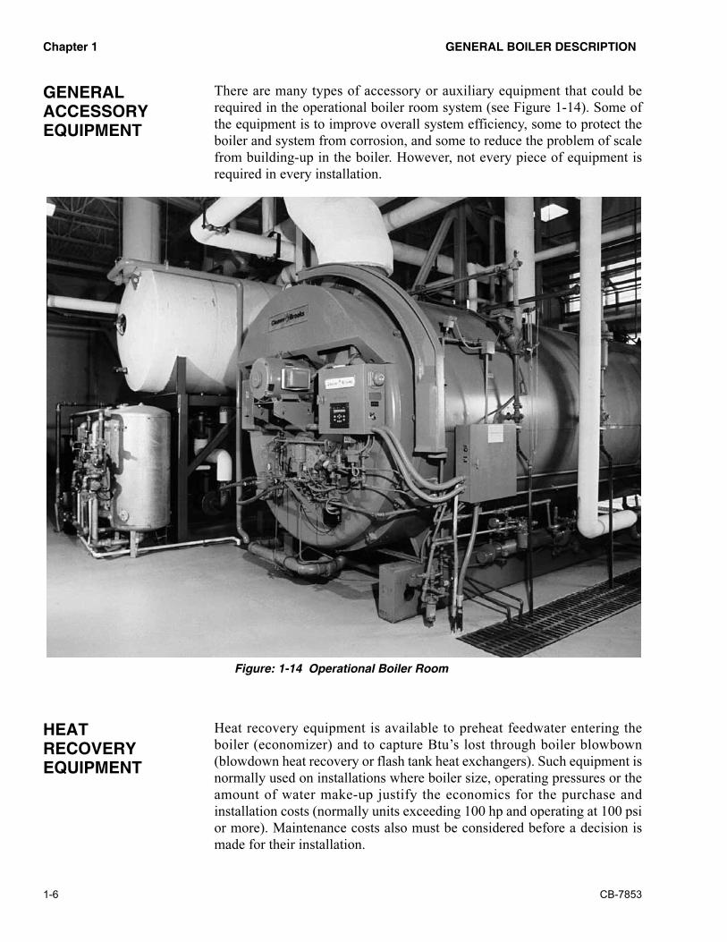
There are many types of accessory or auxiliary equipment that could be
required in the operational boiler room system (see Figure 1-14). Some of
the equipment is to improve overall system efficiency, some to protect the
boiler and system from corrosion, and some to reduce the problem of scale
from building-up in the boiler. However, not every piece of equipment is
required in every installation.
Heat recovery equipment is available to preheat feedwater entering the
boiler (economizer) and to capture Btu’s lost through boiler blowbown
(blowdown heat recovery or flash tank heat exchangers). Such equipment is
normally used on installations where boiler size, operating pressures or the
amount of water make-up justify the economics for the purchase and
installation costs (normally units exceeding 100 hp and operating at 100 psi
or more). Maintenance costs also must be considered before a decision is
made for their installation.
�����
���������
��������
��������
����������
��������
���������60������$��������-���

� � �������� ��� ��������� �������
CB-7853 1-7
�� �� �
��������
Economizers are bent, finned-tube heat exchangers. They are available in
rectangular or cylindrical (see Figure 1-15) styles. The type of boiler and the
overall boiler room layout may dictate which style is utilized.
The boiler feedwater flows through the economizer tubes before it enters the
boiler. The economizer is installed into the breeching between the flue gas
outlet connection on the boiler and the stack. The products of combustion
leaving the boiler flow through the economizer, over the finned tubes,
transferring its heat or Btu’s to the boiler feedwater. The efficiency of the
overall system can be increased by 2% to 4%, depending on fuel being
burned, boiler size, and operating conditions.
There are several methods and equipment used in blowdown heat recovery.
In most cases, the systems are used on continuous or surface blowdown to
control the Total Dissolved Solids (TDS) in the boiler water.
Blowdown heat recovery equipment is used for automatic control of the
continuous blowdown, based on water make-up (see Figure 1-16) and cools
the continuous blowdown to a point where it can be safely dumped to the
sewer system. It transfers heat or Btu’s to the make-up water, thus raising
the temperature of the make-up water before it enters the deaerator or boiler
feed system.
�����������
��������".���2
���$���8��
��������(����%��$9���
-���:���

������� � � �������� ��� ���������
1-8 CB-7853
Another system uses the addition of a flash tank heat exchanger (see Figure
1-17). This system works on the same principle as the blowdown heat
recovery system, however, it also provides the benefit of flash steam. This
flash steam can be reused in the plant, such as being piped to a deaerator and
mixed with the incoming steam in the deaerator.
An additional piece of equipment - the blowdown separator - can be
installed for bottom blowdown (see Figure 1-18). The blowdown separator
reduces the temperature of the bottom blowdown water to a temperature that
would be safe for the sewer system. However, because of the erratic flow of
bottom blowdown, there is little benefit to use a blowdown separator as a
means to raise the temperature of make-up water prior to entering the
deaerator or boiler feed system.
���������������
���������
��������)���&/+�$2
9����*�/�$���
�� �� ��
���������
��������,����%��$.�0�������$%��������
� � �������� ��� ��������� �������
CB-7853 1-9
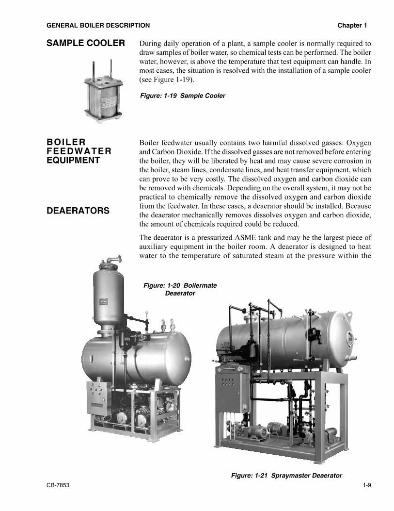
During daily operation of a plant, a sample cooler is normally required to
draw samples of boiler water, so chemical tests can be performed. The boiler
water, however, is above the temperature that test equipment can handle. In
most cases, the situation is resolved with the installation of a sample cooler
(see Figure 1-19).
Boiler feedwater usually contains two harmful dissolved gasses: Oxygen
and Carbon Dioxide. If the dissolved gasses are not removed before entering
the boiler, they will be liberated by heat and may cause severe corrosion in
the boiler, steam lines, condensate lines, and heat transfer equipment, which
can prove to be very costly. The dissolved oxygen and carbon dioxide can
be removed with chemicals. Depending on the overall system, it may not be
practical to chemically remove the dissolved oxygen and carbon dioxide
from the feedwater. In these cases, a deaerator should be installed. Because
the deaerator mechanically removes dissolves oxygen and carbon dioxide,
the amount of chemicals required could be reduced.
The deaerator is a pressurized ASME tank and may be the largest piece of
auxiliary equipment in the boiler room. A deaerator is designed to heat
water to the temperature of saturated steam at the pressure within the
����������
���������3����������
5��������
���������.0�����&���5��������
�������������
�����
���� ����
��������
��������1.��0��������

������� � � �������� ��� ���������
1-10 CB-7853
����������.����+�$2
����������
deaerator. A deaerator provides an effective means for recovery of heat from
exhaust or flash steam, provides a location for returning condensate and
accepts condensate first to reduce excessive make-up water. There are three
types of deaerators available. The tray type is normally used in large utility
plants. Applications that use a deaerator with a packaged boiler typically use
a packed column (see Figure 1-20) or spray type (see Figure 1-21) deaerator.
If plant conditions do not warrant the use of a deaerator, in most cases, a
Packaged Feed System (See Figure 1-22) is used. The packaged feed system
is an atmospheric tank that can heat feedwater to a maximum of 210°F.
Because they are atmospheric tanks, they are equipped with an epoxy lining
or made from galvanized steel. The packaged feed system heats the
feedwater and reduces the amount of dissolved oxygen and carbon dioxide
in the feedwater. However, it’s not as efficient as a deaerator and, therefore,
more chemicals will be required to protect the overall system.
There are many additional pieces of equipment available to remove
impurities in the make-up water before it enters the boiler and system. The
type of equipment required is determined by a water analysis. This
equipment can be classified as pre-treatment equipment.
A surge tank could be used under the following conditions: If there are
intermittent peak loads of condensate that can exceed the surge capacity of
the deaerator - varying pressures or temperatures in condensate - gravity or
pumped condensate that have insufficient pressure to enter the deaerator on
their own (see Figure 1-23). Surge tanks are atmospheric and accept
�������������%�����.�&���
������������

� � �������� ��� ��������� �������
CB-7853 1-11
condensate and make-up water before it goes to the deaerator. Surge tanks
can be lined with an epoxy coating to prevent corrosion. The condensate and
make-up water mix into a blend temperature as determined by the
percentage of each.
Filters (see Figure 1-24) are available to remove free chlorine, some
dissolved organics and sediment. They can also remove suspended solids,
colloidal matter, sand and iron.
There are carbon filters, multilayered filters, sand or iron filters. There can
be lined tanks, ASME code tanks and automatic operation based on a time
clock, pressure differential switch or water meter. They can protect such
items as water softeners, dealkalizers, and reverse osmosis equipment, etc.
There are many different types of water softening systems available today.
No attempt will be made in this section to explain the operation of them all.
Probably the most popular and widely used type of water softening method
is the sodium zeolite softening process (see Figure 1-25), more commonly
referred to as zeolite softening. This type of softening process will remove
the calcium and magnesium salts from water and reduce it to zero hardness.
Through an ion exchange process, water softeners remove hardness and
replace it with highly soluble sodium ions; thus preventing scale buildup on
heat transfer surfaces. Removing hardness also reduces the need for
chemical treatment used to control scale. A water softener can be single or
multiple tank and automatic or manual operation.
The zeolite type of softening process can be used in conjunction with other
external or internal treatment processes or equipment for boilers. Other
types of equipment that could be in a system are:
1. Dealkalizer - Employ an ion exchange to reduce Bicarbonate Alkalinity. It
replaces bicarbonate, sulfate, nitrate, and silica with chloride ions.
������������������������������"�������$%����$��&
�������������
��������
������������

������� � � �������� ��� ���������
1-12 CB-7853
2. Reverse Osmosis Units - This type of unit is used to reduce dissolved solids in
make-up water. The unit uses a semi-permeable membrane that allows water
to flow through it and at the same time restricts the flow of dissolved solids.
The dissolved solids remain in solution and are carried out of the unit to waste.
While the amount of chemicals added to a boiler and system can be reduced
with the use of pre-treatment equipment, chemicals still have to be added.
Chemicals are normally added with the use of chemical feeders.
Note: Contrary to common belief, hot water boilers often require treatment
to a limited degree.
There are several different methods that can be utilized to feed chemicals
into a boiler. However, there are two basic types and most chemical feed
equipment can be classed in one or the other.
First and simplest is the pot type Manual Shot Feeder. Pot type feeders are
frequently installed in small boiler plants, on the discharge side of the boiler
feed pump. The feeder is convenient and economical for the injection of
precipitating chemicals in closed loop or low make-up systems.
The second group of chemical feeders is the Chemical Feed System (see
Figure 1-26) and Metering Pumps (see Figure 1-27). These systems provide
for feeding chemicals into a boiler at a predetermined and controlled rate.
Chemicals for oxygen removal, pH adjustment or any of the surface active
organic and inorganic chemicals for prevention of deposits or corrosion in
distribution lines, would normally be added to the system with this type of
arrangement.
Depending upon the degree of sophistication, this type of system could
include a chemical tank, pump, complement of valves, piping, etc., plus
some type of control mechanism, timer or meter.
���������(�/���������%.�&���
���������)�/������
7�����$�'��0
��������
�������

� � �������� ��� ��������� �������
CB-7853 1-13
The Flame Safeguard or Programming Control on boilers are designed to
ensure that the start-up of the burner follows a definite timed sequence of
operation. In addition to the sequence of operation and after the flame has
been established, the Flame Safeguard monitors the flame and sets the firing
rate of the burner, as determined by the boiler firing rate controls. They also
monitor, through the boiler controls, items such as boiler pressure or
temperature, fuel pressure or temperature and they provide for normal shut
down of the burner if the load demand is satisfied, or shut down and alarm
if there is a safety shut down condition.
The Flame Safeguards or Programming Control installed on a boiler can be
classified into three categories:
1. Electro Mechanical
2. Solid State Electronic
3. Micro Processor
The electro mechanical controls have been used from around 1950 until
1984.
Solid state electronic controls were introduced in 1984. This type of control
provides for more alarm or monitoring functions than the electro
mechanical controls. The micro processor controls (see Figures 1-28 & 1-
29) introduced in 1989 not only provide the functions as the other controls,
but also have the ability to send information to computers and work in
conjunction with some energy management systems. The micro processor
type of controls are standardly furnished on some of today’s modern boilers.
���������,���9��;#�.™'��������
7�$�����$���$����
���������1���),3�����.�<�����%
�����
��������
��������

������� � � �������� ��� ���������
1-14 CB-7853
There are numerous types of stacks available. They could be steel stacks
with portions material insulated, prefabbed single wall stainless steel,
double wall material insulated, double wall air insulated, or triple wall air
insulated. See Figure 1-30.
The type of heating equipment to be used, the fuels to be burned, the exhaust
temperatures of the equipment, the building use and type of construction
materials used have to be considered when a stack is selected. The job-site
elevation, site dimensions, the need for an offset, drains, fittings, roof
penetration, etc., must also be considered.
An oxygen trim system (see Figure 1-31) is designed to continuously
monitor oxygen concentrations in the boiler flue gas and adjust fuel or air
flow to maintain the oxygen level at a set point. The system will compensate
for changes in ambient air temperature, barometric pressure, humidity and
slight variations in fuel characteristics.
���������62+���.�&���
������
�2�������������
���������3.���2&

CB-7853 2-1
�"�#$���)
'&#��$'&�
Before a new boiler is initially fired, it should be given a complete and
thorough inspection on both the fire side and water side. Examination is
necessary of all the pressure parts, drums, tubes, water column(s), blowoff
and blowdown valves, safety or safety relief valves, baffles, nozzles,
refractory setting, seals, insulation, casing, etc. If any foreign material is
found in the boiler, it should be removed.
The period of initial inspection is also a good time for the insurance
inspector to check out the boiler. As a general rule, the inspectors like to
have an opportunity to inspect the boiler prior to the hydrostatic test. Any
state or local inspectors, when required, should also be contacted.
Note: All electrical service to
the bo i le r mus t be
disconnected and locked
into the off position. It is
suggested that only low
voltage portable lighting be
used for in ternal bo i ler
inspections.Only approved,
properly guarded extension
cords with waterproof fittings
should be used, and al l
connections are to be made
exterior to the boiler. Light
bulbs should be equipped
wi th exp los ion-p roo f
guards.All federal, state,
local or insurance codes
regarding confined space
requirements or lock out of
electr ical equipment, or
valves in steam lines, fuel
lines, and water lines, must
be followed.
���������
���� �����
��������� ������������������ �����������

������� ������ ���
2-2 CB-7853
When a hydrostatic test is required in order to comply with state, local or
insurance company requirements, a series of actions are necessary. It first
must be determined if the hydrostatic test will be at 1-1/2 times the operating
pressure or 1-1/2 times the design or maximum allowable working pressure.
Boilers are hydrostatically tested during manufacturing at 1-1/2 times the
design or maximum allowable working pressure and the Manufacturer’s
Data Report (H-2 Section IV Boilers or P- 2 Section I Boilers) is completed.
A job site hydrostatic test is normally at 1-1/2 times the operating pressure,
or below the safety valve settings, and is done to determine if any tube
connections were loosened during shipment. However, some installations
require a hydrostatic test at 1-1/2 times the design or maximum working
pressure. Depending on which test is required and the juristic body
involved, some of the following may be applicable:
1. Safety valves may have to be removed (see Figure 2-2) and blind flanges
installed over the openings. If safety valves are equipped with threaded inlets,
they may be removed and the boiler openings can be plugged.
2. The safety valves may be gagged. However, this method is not a normally
recommended practice. The gag should be used only for the hydrostatic test
and must be removed as soon as the test is completed. The gag should be
installed on the valve and extreme care should be exercised not to tighten the
gag screw too tightly. Hand tight torque is generally sufficient. Damage to the
spindle and/or seat of the valve may result if the gag is too tight. After safety
valves have been gagged for the hydrostatic test and if there is any doubt about
their operation, the valves should be removed and sent to an authorized testing
facility and tested before the boiler is put into operation.
3. Blowoff valves, blowdown valves, non-return valves and other isolating valves
should all be closed tight. All lines leading to or from the boiler that lead to any
equipment that might be damaged by the hydrostatic pressure should be
blocked off either by valves or by disconnecting and capping the piping. Water
column(s), gauge glass(es), continuous blowdown lines, chemical feed lines,
pressure control lines, drain lines, etc., should all be checked and isolated if
necessary. All blowdown and drain lines should be piped to a point of safe
������ ����
�������
���������� ��!"��#��

������ ��� �������
CB-7853 2-3
discharge. The vent valve on top of the boiler, the steam pressure gauge, water
column, and the water fill line should be the only lines not plugged or blocked
off. The steam pressure gauge may need to be checked and calibrated with a
dead weight tester.
With the vent valve on top of the boiler open, or in the water column piping
(see Figure 2-3) open, water can now be fed into the boiler. Water used for
the hydrostatic test should be at ambient temperature, but in no case less
than 70°F. The appropriate hydrostatic test pressure can then be applied. The
test should be conducted in one of several methods:
1. The boiler should be filled slowly at the proper water temperature, venting air
through the boiler vent valve. When the boiler is full and all of the air has been
vented, the boiler vent valve can be closed. Then the pressure can gradually be
raised until the maximum hydrostatic test pressure has been reached.
2. The pressure shall be under close control at all times so that the required test
pressure is never exceeded. If a hydrostatic test at 1-1/2 times design or
maximum working pressure is applied, the pressure cannot be allowed to
exceed more than 6 percent above the design or maximum working pressure
for power boilers (Section I), or more than 10 psi for heating boilers (Section
IV). A heating boiler should be inspected while under the hydrostatic test
pressure, and all joints and connections inspected closely for leakage. Close
visual inspection for leakage is not required on a power boiler at this time.
3. For power boilers the hydrostatic test pressure may be reduced to the design or
maximum allowable working pressure as shown on the manufacturer’s data
report and maintained at this pressure while the boiler is carefully examined.
After the boiler is found to be tight, the pressure can be released slowly and
the boiler drained. Open the vent valve on the boiler during draining. After
the boiler is drained, the blind flanges, plugs, caps and gags (if used) should
be removed and all the lines, etc., put back into operating condition.
During the hydrostatic test inspection of the boiler, a few so called
“weepers” may be observed. If the weeping tubes are just a few in number
and the leak is just a drop or two every few minutes, this is not of great
concern. Chances are very good the weepers will dry up completely when
the boiler is fired. If, however, there are tubes leaking at a rate of more than
one or two drops every few minutes, then the leaking tubes should be re-
rolled.
If re-rolling of any tubes is required during the initial hydrostatic test
inspection, the boiler inspector generally is present to observe the operation
during the re-rolling, or for a re-inspection after the re-rolling. All re-rolling
of any previously rolled and flared tubes should be done with straight rolls
only, no flare.
���������
��������$���������%�
���"���"��#�

������� ������ ���
2-4 CB-7853
Note: Rolling of tubes in a boiler should be done by an experienced
boilerperson. If there is not a qualified boiler repairperson in the
customer’s organization, then either the boiler manufacturer, their
authorized representative or a boiler repair shop should be called in
to roll the tubes. After the leaking tubes have been re-rolled, it will
be necessary to hydro-test the boiler once again, to make sure
everything is tight.
An external inspection of an existing installation can be made while the
boiler is in operation. Close inspection of the external parts of the boiler, its
accessories, and connections should be made before taking the boiler off the
line and securing. Notes of all conditions that need attention should be made
so that proper repairs can be taken care of after the boiler is shut down.
When conditions will permit, the shutdown of an existing installation can
often be timed to coincide with the annual or semi-annual inspection, at
which time the insurance and/or state boiler inspectors and feedwater and
boiler water treatment consultant, can be present.
The burner flame shall be extinguished and fuel supply lines shut off and
locked where feasible. Where oil is used, atomizers or oil gun assemblies
should be removed from the burner. Where gas is used, the supply lines shall
be blanked off, or shutoff cocks closed and locked. Care must be taken to
ensure no fuel or fuel vapors can enter the boiler furnace while the unit is
shut down.
Before draining the boiler, it must be determined that the boiler and setting
have cooled sufficiently to prevent damage to the boiler or to prevent the
baking of deposits that may be present on the heating surface. It is
recommended that the boiler be drained while there is sufficient heat present
to dry out the water side of the boiler when ventilated by opening manhole
and/or handhole covers. However, the temperature of the water removed
from the boiler must be below the maximum temperature that the drain
system can tolerate.
Before opening the manhole or handhole covers and entering any part of the
steam generating portions of the unit, the boiler stop or non-return valve and
the header stop valve must be closed and the drain valve or cock (bleed
valve) between the two valves opened. All valves should be tagged and
preferably padlocked. After draining the boiler the blowdown valves should
be closed and padlocked. To prevent someone from being burned by hot
steam, care must be taken to ensure no steam can enter the boiler while the
unit is open.
The water surfaces of drums and tubes should preferably not be cleaned,
unless otherwise agreed, until after the authorized inspector(s) have had the
opportunity to observe the conditions. Examination of the boiler water side
before cleaning will assist in judging the adequacy of the feedwater and
water treatment program in preventing scale formation, corrosion, or
excessive accumulation of sludge. Also the feedwater and boiler water
�������������
���� �����
� ��������
����������

������ ��� �������
CB-7853 2-5
treatment consultant should be notified to permit him/her to inspect the
water side of the boiler during this period.
Loose deposits should be washed out with a high pressure stream hose.
Because of the possibility of tube joint chilling, all wash water should be at
ambient temperature, but in no case less than 70°F. It is advisable to
disconnect the blowdown piping from the boiler and run the wash water to
waste, or to provide strainers in the blowdown openings to prevent foreign
matter from lodging in blowdown piping and valves.
Many of the internal waterside surfaces of boilers cannot be cleaned
properly by mechanical means. When it becomes necessary to clean these
surfaces, chemical cleaning must be employed. Such chemical cleaning can
be acidic or basic, depending upon the type of deposits that need to be
removed. When chemical cleaning is required, care must be taken to avoid
damage to both ferrous and non-ferrous materials through improper use of
the solvents. Also, be aware of the potential dangers involved when dealing
with corrosive solutions and possible explosive and toxic products of the
cleaning process. Work of this kind should be supervised by personnel
specially qualified by training and experience in this highly technical field.
It is important to maintain adequate ventilation in the boiler room during
any chemical cleaning procedures. Before internal inspections are
performed, and after the cleaning process has been completed, the boiler
must be properly ventilated. Appropriate lighting as previously described
(see Figure 2-1) must be used during internal inspections.
Careful inspection of the internal areas of the pressure parts should be made
to detect any corrosion or cracking of the tube sheets, tube ends, furnaces,
or drums, signs of leaking tubes, excessive thinning of the tubes from
repeated rolling, and the condition of any ferrules and nipples within drums.
Also note any evidence of corrosion or cracking due to leakage at manholes
or handholes.
Other points to look for when examining the interior of the boiler include
cracks, broken stays, cracked fittings, corrosion, erosion, scale, and thin
places in the drums. The upper half of drums in the steam space shall be
examined particularly for signs of grease, oil, or similar deposits.
The interior of the tubes or the space between the tubes shall be examined
for scale and deposits. In the case of a Firetube boiler, a small light may be
lowered between the tubes to make sure there is no restriction to impede
boiler circulation. The condition of all drum internals should be observed.
Internal feed pipes, dry pans, scrubbers, baffles, chemical feed pipes,
surface blowoff and bottom blowdown connections, and other accessories
shall be examined to see that their openings and perforations are free from
deposits. All interior fittings shall be examined for loose connections and
damaged or missing gaskets.

������� ������ ���
2-6 CB-7853
����� �
����������
If fusible plugs are used, see that they are kept in good condition and that
they are not used for more than one year. The ASME Code states that the
fusible plug shall be replaced at least once each year. However, the use of
fusible plugs is no longer required by ASME Codes. Usually the best time
for replacing a fusible plug is during the time the boiler is down for the
annual inspection. A fusible plug is defined as a hollow threaded plug. The
hollowed portion is filled with a low melting point material and it is usually
located at the lowest permissible water level.
Examination of the fireside areas of the unit should include checking the
condition of baffles, refractory and metal, setting and poured refractories,
gas passes, sootblower lances and support bearings. All brick, tile or
refractory walls and door linings should be inspected carefully for spalling
or decay of refractory surfaces, cracking and settlement. Any such observed
conditions should be cleaned out and repaired. Cracks or holes in walls and
baffles will permit short-circuiting of the combustion gases. Such short-
circuiting will eventually cause a burnout and failure of the affected part,
and will change the combustion, as well as result in a loss in boiler
efficiency. A deteriorated refractory and/or insulation can usually be
detected during operation by location of hot spots on the casing or other
outer covering of the furnace and boiler, or during a combustion gas
analysis.
External examination of the boiler should include the visual inspection of
the outer surfaces during operation as stated earlier. Other external points
that should be inspected and examined include the gauge glasses, water
column(s), water level controls, high and low-water alarms and cutoffs,
blowoffs, blowdown, feed water valves, check valve, feed line at the entry
to the boiler, safety valves, and boiler stop valves or non-return valves.
All piping connecting these various controls and accessories should be
checked to make certain there are no deposits to stop or impede proper flow
through the piping and to the controls. Most installed piping for these
controls includes cleanout plugs at critical points. The cleanout plugs should
be removed and the pipe rodded out to remove any scale, mud or sediment.
The condition of the water column(s), gauge glass and trycocks (if installed)
should be carefully observed. Make sure the water pipe connecting the
water column drains toward the boiler. The water column should be checked
with respect to its proper level in relation to the normal water level in the
boiler. In Firetube boilers check the position of the water column gauge
glass by leveling across the top row of tubes. Replace or repair any part of
this control before restoring the boiler to service.
��������
����������

������ ��� �������
CB-7853 2-7
All connecting piping and all exterior piping supports should be inspected
to ensure that no excessive stresses or strains are exerted on the pressure
parts of the boiler.
For future reference a written report should be made of all points observed
during the inspection. Immediate steps should be taken to correct those
items that can be corrected at the completion of the inspection. Careful
consideration should be given to those points concerning conditions of the
pressure parts, which will require changes in operating procedure or
maintenance.
��������������� �
Before making any attempt to start a burner-boiler unit, the manufacturer's
instruction manual should be read thoroughly in order to get a good
understanding of how the burner operates. The operator should be familiar
with the various parts of the burner and understand their function and
operation.
To describe all of the different types of fuel burning equipment is beyond
the scope or intent of the guide. The guide covers points that can, with slight
variations, be applicable to many types of equipment.
The burner should be checked over thoroughly to ascertain all parts are in
proper operating condition. Some of the points to check are:
1. Fuel lines: All of the fuel connections, valves, etc., should be inspected
thoroughly. Make sure all the joints are tight, pressure gauges and
thermometers are in place and tight, and valves are operative. Fuel lines should
be checked for leakage.
2. Check all of the burner linkage for tightness and wear at connecting points. If
possible to do so, check linkage for travel and proper movement.
3. The electrical wiring should be checked very carefully. Make sure all
connections are tight. Check all the terminal strip connections. Sometimes the
vibration from shipping or operation will loosen them. Plug-in controls, relays,
timers, switches, etc., should all be checked to ensure the wires are tight. Check
rotation of fan, pumps, and air compressor motors, etc.
All of the various interlocks, limits and safety controls should be checked to
ensure that they are operational and set at the proper safe set point. An actual
operating test of the controls cannot be made until the burner is in operation.
All or most all of the following limits may be found on the average package
boiler/burner, depending on the insurance regulations, federal, state or local
codes being complied with.
������������������������ ����
1. High Limit Pressure Control
2. High Limit Temperature Control (Hot Water)
3. Operating Limit Pressure Control (Steam)
��������������
���� �����

������� ������ ���
2-8 CB-7853
4. Operating Limit Temperature Control (Hot Water)
5. Modulation Pressure Control (Steam)
6. Modulation Temperature Control (Hot Water)
7. Low Water Cutoff/Auxiliary Low Water Cutoff
8. Flame Failure (Part of Flame Safeguard Function)
9. Combustion Air Proving Switch
10. Atomizing Media Proving Switch, for Oil Burner only (Steam and/or Air)
11. Low Oil Temperature Switch
12. Low Oil Pressure Switch
13. High Oil Pressure Switch
14. Low Gas Pressure Switch
15. High Gas Pressure Switch
16. Low Fire Switch
17. High Fire Switch
There are other operating limit interlocks that can be added to the control
system, depending on the degree of sophistication.
���� ��������������
All of the boiler room accessory or auxiliary equipment should be inspected
thoroughly to ensure everything is in good working order and ready for
operation.
�����������
Manufacturer's drawings and instructions should be followed when making
an inspection of the economizer. Check for proper installation, check
breeching duct work, arrangement, alignment and expansion provisions.
Tubes and headers should be checked to make sure there is no plugging nor
obstructions on both the waterside and fireside of the tubes. Check
feedwater piping to the economizer inlet header and the piping between
economizer and boiler. Shutoff and check valves, isolating valves,
feedwater control valve and relief valves, etc., test connections,
thermometers and pressure gauges should all be inspected and checked for
proper safe settings and operation.
�����
Boiler feed pumps, transfer pumps, condensate pumps - all of the pumps in
the system-should be inspected. Piping connections to the pump suction and
discharge ports should be checked. Adequate provisions should be made for
proper expansion to prevent undue strains imposed on the pump casing.
Drain lines, gland seal lines, recirculation lines, etc., should all be checked

������ ��� �������
CB-7853 2-9
to determine if they are in accordance with the manufacturer's
recommendations. The coupling alignment should be checked to ensure no
misalignment exists. If the coupling alignment is not up to the pump or the
coupling manufacturer's recommendations, they must be realigned so they
are within the manufacturer's recommended tolerances. After all of the
above precautions have been carried out, check the pump for proper
rotation. The appropriate pump motor starter can be momentarily energized
for this operation. Be careful not to hold the starter in too long.
� � � ��!����"���#���
The continuous blowdown heat recovery, flash tank heat exchanger and
blowdown separator piping, both drain and vent, should be inspected for
leaks, proper slope of drain lines, and proper valve operation. All controls
and automatic valves should be checked for proper safe settings and
operation. The tanks should be inspected to ensure no sediment is blocking
top outlet and/or drain lines.
$��� ���� ��
Ensure there are no leaks in the sample-in and sample-out lines or in the
cooling water in and out lines. Check to ensure none of the lines are plugged.
%��������&$�����'���&��������(���$������
Installation of this equipment should conform to manufacturer's
recommendations. Check all piping for proper connections. Check valves
and controls to be sure they are installed properly and set to proper operating
parameters.
Check internals of the tank(s) and remove any foreign material. The inside
of the tank should be wiped thoroughly to remove any oil or grease from
manufacturing. Make sure all pipe connections leading into and out of the
tank are clear. Vent valves, overflow drainer and relief valves, etc., should
be piped to a point of safe discharge.
There is a possibility that some installations may have problems with
corrosion in their tanks. If such problems occur, the insurance and/or state
Note: Care should be exercised when checking for
proper rotation. Some pumps may be seriously
damaged if the pump is rotated in the wrong direction.
Where the possibility of damage to the pump does exist
(refer to the manufacturer’s instruction manuals), it is
advisable to disconnect the coupling before checking
the motor rotat ion. The coupl ing can then be
reconnected and aligned after it has been determined
the motor rotation is correct.

������� ������ ���
2-10 CB-7853
boiler inspector should inspect the tank. There are brushed-on or baked-on
coatings available to prevent tank corrosion. Corrosion of the tank(s) may
be a sign of system or mechanical problems.
(� ����
The filter inlet and outlet piping and drain lines should all be checked
against installation drawings and for tightness. All electrical wiring should
be checked for tightness at connecting points. Ensure all filter beds are clear
of contamination. Inspect tanks to ensure that if a lining was installed, it is
still in place. All automatic, pneumatic or pilot operated valves, water
meters, or pressure differential switches, etc., should be inspected, set at
proper set point and tested for operation.
)�����$�*�����&%�� �� ����&"�#������������
All inlet and outlet piping and drain lines should be checked against
installation drawings and for tightness. All electrical wiring should be
checked for tightness at connecting points.
Depending on the particular system being used, the tanks should be charged
with the required filtering or exchange media and chemical solutions.
All automatic, pneumatic or pilot operated valves should be inspected, set
at proper set point and tested for operation.
+����� �(�����
There are several different methods of feeding chemicals into a boiler. There
are two basic types, however, and most chemical feed equipment can be
classed in one or the other of these groups.
First and simplest of the systems is the pot type shot feeder. Pot type feeders
are frequently installed in small boiler plants on the suction side of the boiler
feed pumps. The feeders are convenient and economical for the injection of
the precipitating chemicals, such as phosphates, caustic soda and soda ash
to boilers.
Such chemicals as sodium sulfite (for oxygen removal), caustic soda or soda
ash (for pH adjustment) or any of the surface active organic and inorganic
chemicals (for prevention of deposits in distribution lines) should not be fed
through this type of feeder.
The second group of chemical feeders involves the pump type of feeder,
which provides for feeding chemicals into a boiler at a predetermined and
controlled rate. Depending upon the degree of sophistication, this type of
system usually includes a chemical tank, pump, complement of valves,
piping, etc., plus some type of control mechanism (timer or metering).
This equipment can be purchased as a packaged unit ready for installation.
When the equipment is purchased as separate items, they have to be
mounted, piped and checked out for proper operation. The most important

������ ��� �������
CB-7853 2-11
part of checking out this equipment is to examine them for leaks, proper
installation, pump rotation and operating controls.
�����������
On large industrial or utility boilers, the economizer is normally an integral
part of the boiler. For smaller boilers, packaged heat recovery equipment is
external.
Economizers are normally bent tube exchangers. The boiler feedwater flows
through the tubes on its way to the boiler. The tube bank is assembled into
a section of duct work which is located in the breeching between the flue gas
vent connection on the boiler and the stack or chimney. The products of
combustion leaving the boiler flow through this duct, over the tube bank,
giving up its heat to the boiler feedwater.
Manufacturer's drawings and instructions should be followed when making
inspection of the economizer. When inspecting an economizer, check for
proper installation, check breeching duct work, arrangement, alignment and
expansion provisions. Make sure all internal baffling, tube arrangements,
headers, tube sheets, etc., are installed in accordance with manufacturer's
recommendations. Tubes and headers should be checked to make sure there
is no plugging nor obstructions. Check feed piping to the economizer inlet
header and piping between the economizer and the boiler. Check and inspect
shutoff and check valves, isolating valves and relief valves, test
connections, thermometers and pressure gauges.

������� ������ ���
2-12 CB-7853
�����

CB-7853 3-1
�"�#$���*
�'�'&���$��$+#
After the initial inspection is completed, the new boiler is ready for startup.
Startup can be the most critical period in the life of the boiler. The
manufacturer's installation and/or operating instruction manuals should be
referred to, and their contents thoroughly understood by all parties involved
in the initial startup and eventual operation of the boiler(s). The personnel
responsible for operating and maintaining the boiler should be present
during the initial startup period.
Note: No attempt should be made
to initially fire the boiler until the
fo l low ing po in ts have been
checked:
1. A sufficient water supply is available. Water used to initially fill the
boiler must be at ambient temperature, but not less than 70°F. Water
used during the boil out period should be at the normal temperature of
the water coming from the deaerator or packaged feedwater system.
2. Steam piping, blowoff and blowdown lines, etc. must be inspected
and ready for operation. All piping must be inspected for adequate
support and expansion provisions.
3. All fuel supply lines must be checked for tightness and leaks.
Strainers are most important to the safe operation of gas and/or oil fired
units.
4. Electrical power lines to the boiler/burner unit are connected and the
voltage required is verified. (Checking out of the burner and controls is
covered in Chapter 2.)
5. Hydrostatic test has been completed.
6. Any walkways, platforms, stairs, and/or ladders, etc., that are needed
to permit proper access to the boiler/burner, are installed and ready for
use.
��������������
� �������� ���

������� �� � ����������
3-2 CB-7853
It is recommended that a newly installed boiler be boiled out. Its internal
surfaces could be fouled with oil, grease, and/or other protective coatings
from the manufacturing of the boiler. Boiling out will also remove any
remaining mill scale, rust, welding flux, or other foreign matter normally
associated with manufacturing or shipment. All contamination needs to be
removed since it lowers the heat transfer rate, and could cause localized
overheating.
Existing boilers that have had any tube replacement, re-rolling or other
extensive repairs to the pressure parts should also be boiled out. The
lubricant used for rolling tubes, plus the protective coating on the new tubes,
must be removed by boiling out before the repaired boiler can be put back
on the line.
There are several methods used to perform the boilout operation. The
boilout chemicals that are added to the water create a highly caustic
solution, which upon heating dissolves the oils and greases and takes them
into solution. After the period of boil out and blowing down the boiler, the
concentration is diluted enough that practically all of the oils and greases
and other matter have been eliminated.
Since the guide covers firetube and watertube boilers, we will divide the
boilout instructions into two (2) parts, one for firetube and one for
watertube. The procedures have been recommended by Cleaver-Brooks for
many years.
Note: No chemicals should be added to the boiler until the hydrostatic test
has been completed and the burner has been checked to ensure a low fire
flame can be established.
The suggested procedure for boiling out new units prior to initial firing is as
follows.
Water relief valves and steam safety valves must be removed before adding
the boilout solution so that neither it nor the grease which it may carry will
contaminate the valves.
All valves in the piping leading to or from the system must be closed to
prevent cleaning solution from getting into the system.
Soda ash and caustic soda are the suggested chemicals for cleaning of
boilers. The quantities will vary according to conditions, but an amount
from 3 to 5 pounds of each chemical per 125 gallons of water is suggested.
A small amount of laundry detergent should be added to this solution to
serve as a wetting agent. Refer to manufacturer's information data report for
the water capacity of the boiler.
�������� ����
� �� �

�� � ���������� �������
CB-7853 3-3
When dissolving chemicals, the following procedure is suggested. Warm
water should be put into a suitable container. Slowly introduce the dry
chemical into the water, stirring it at all times until the chemical is
completely dissolved. Add the chemical slowly and in small amounts to
prevent excessive heat and turbulence.
Note: Use of a suitable face mask, goggles, rubber gloves, and protective
garments is strongly recommended when handling or mixing caustic
chemicals. Do not permit the dry material or the concentrated solution to
come in contact with skin or clothing.
Fill the pressure vessel with clean water until the top of the tubes are
covered. Add the cleaning solution and then fill the boiler to the top. An
overflow pipe should be attached to one of the top boiler openings and
routed to a safe point of discharge. Water relief or safety valve tappings are
usually used.
The boiler should then be fired intermittently at low fire rate, sufficient to
hold solution just at the boiling point. During this slow firing, a small
amount of fresh water should be periodically introduced into the pressure
vessel to create an overflow that will carry off surface impurities. Ensure
this overflow is discharged to a safe point of discharge as determined by
federal, state, or local codes.
The boilout operation should be carried out for 6 to 8 hours minimum and
then the boiler should be permitted to cool.
When the temperature of the water in the boiler has fallen to 120° F or less,
the boiler should be drained.
Remove handhole and manhole plates and rinse or flush internal waterside
surfaces until they are clean and free of deposits, using a high-pressure
water hose. The water temperature should be ambient, but not less than
70°F.
After the boilout procedure has been completed, consideration must be
given to the possibility that contaminated materials could enter the boiler
from the system. Refer to Chapter 4 of the guide and follow the procedures
given there regarding feedwater treatment.
��������� ��������������������
No later than three months after initially placing the boiler into operation
and thereafter as conditions warrant, the pressure vessel should be drained,
handhole and manhole covers removed, and the internal waterside surfaces
inspected for corrosion, pitting or formation of deposits. Upon completion
of the inspection, the pressure vessel interior should be flushed out, as
required, with a high-pressure hose.

������� �� � ����������
3-4 CB-7853
The water temperature should be ambient, but not less than 70°F. If deposits
are not fully removed by flushing, an immediate consultation with your
water consultant or feedwater treatment company may be needed. In
extreme cases, it may be necessary to resort to acid cleaning. Should acid
cleaning be required, professional advice is recommended.
Inspections will indicate the effectiveness of the feedwater treatment
program. Water conditions and the amount of make-up water required are
also factors to be considered in establishing frequency of future pressure
vessel washout periods. At later washouts, the condition of the waterside
surfaces will indicate the effectiveness of the water treating program, as well
as the suitability of the intervals between washouts. A feedwater consultant
or a water treatment service should include periodic pressure vessel
inspection and water re-analysis.
��������� �����������������������
In theory, a hot water system and boiler that have been initially cleaned and
filled with raw water will require no further cleaning or treatment. However,
the system (new or old) could allow the entrance of air and the unintended
introduction of raw makeup water that can lead to pitting, corrosion, and
formation of sludge, sediment or scale on the pressure vessel.
Therefore the pressure vessel waterside should be inspected no later than
three months after initially placing the boiler in operation, and periodically
thereafter, as indicated by conditions observed during inspections. At
inspection time, the pressure vessel should be drained, handhole and
manhole covers removed, and internal waterside surfaces inspected for
corrosion, pitting or formation of deposits. Upon completion of the
inspection, the pressure vessel interior should be flushed out as required
with a high-pressure hose. The water temperature should be ambient, but not
less than 70°F. If deposits are not fully removed by such flushing, immediate
consultation with your water consultant or feedwater treatment company
may be required. In extreme cases, it may be necessary to resort to acid
cleaning. Should acid cleaning be required, professional advice is
recommended.
Inspections will indicate the effectiveness of the feedwater treatment
program, Water conditions and the amount of make-up water required are
also factors to be considered in establishing frequency of future pressure
vessel washout periods. At later washouts, the condition of the waterside
surfaces will indicate the effectiveness of the water treating program as well
as the suitability of the intervals between washouts. A feedwater consultant
or a water treatment service should include periodic pressure vessel
inspection and water re-analysis.
There is a tendency to mistakenly assume that a hot water system is without
leakage because of the difficulty of measuring the actual quantity of makeup
water added to the system during operation. Since raw makeup water
requires treatment in the same manner as water used for complete filling, a

�� � ���������� �������
CB-7853 3-5
water meter, capable of accurately recording low rates of flow, is
recommended for installation in the makeup water line to the system or
boiler. A meter will provide guidance in determining the amount of raw
water admitted and the additional water treatment required.
�����������������������
It is suggested that temporary gauge glasses be installed during the boiling
out operation and that rubber gaskets be used with a temporary round glass.
A prismatic gauge glass, if supplied, should be removed, and a temporary
round gauge glass should be substituted.
Wipe out as much excess oil as possible from the drums with clean rags.
Clean out any loose debris from the drums.
Internal drum fittings, feed distributing pipes, deflector baffles, etc., if not
already fastened in place, should be placed in the drum during the cleaning
process. Any of the fittings or pieces that are loose should be hung in
position or securely placed in the steam drum during the boiling out period
in such a manner that no tube ends are obstructed.
Soda ash and caustic soda are the suggested chemicals for cleaning of
boilers. The quantities will vary according to conditions, but an amount
from 3 to 5 pounds of each chemical per 125 gallons of water is suggested.
A small amount of laundry detergent should be added to this solution to
serve as a wetting agent. Refer to the manufacturer's information data report
for the water capacity of the boiler.
When dissolving chemicals, the following procedure is suggested. Warm
water should be put into a suitable container. Slowly introduce the dry
chemical into the water, stirring at all times until the chemical is completely
dissolved. Add the chemical slowly and in small amounts to prevent
excessive heat and turbulence.
Note: Use of a suitable face mask, goggles, rubber gloves, and protective
garments is strongly recommended when handling or mixing caustic
chemicals. Do not permit the dry material or the concentrated solution to
come in contact with skin or clothing.
Fill the boiler with water at ambient temperature but not less than 70°F, to a
point just below the manway opening in the upper drum. Add the chemicals
in solution through the manway, or through the upper drum vent valve, or
through the chemical feed line. Close and secure the manway cover.
Fill the boiler with water to 1" to 1/2” below the top of the gauge glass. The
normal operating level is at about the center of the gauge glass. Exercise
caution to prevent water from spilling over into the superheater, if the boiler
is so equipped.
��������� �� �

������� �� � ����������
3-6 CB-7853
Open the steam drum vent valve. If the boiler is equipped with a superheater,
open the superheater drain and vent valves. Recheck the feedwater supply,
gauge glass, pressure gauge, and position of all valves.
Start the burner and allow the boiler to warm up slowly. When steam vapor
is noticed at the boiler vent, close the vent valve. The superheater inlet drain
valve (if provided) should be closed, but the superheater outlet drain valve
should be left open enough to permit continuous cooling of the superheater
tubes. Allow the boiler pressure to increase at a rate not to exceed 50 psi per
hour until the pressure has reached half of the normal operating pressure-not
less than 80 psi but not to exceed 150 psi. Cycle the burner at low fire to
maintain the pressure for approximately six (6) hours.
During the pressure raising and boiling out period, keep the water above the
bottom of the gauge glass by adding water as required.
At the completion of the boilout period, shut the burner off. Add water
slowly until the gauge glass shows full. Blow down through the continuous
blowdown line in the steam drum, until the water falls to approximately the
center of the gauge glass. From this point, blow off with the bottom blowoff
valves until the water level falls to within approximately 2" of the bottom of
the gauge glass. The water column and gauge glass should also be blown
down.
After each blow, refill the boiler to 1" to 1/2” below the top of the gauge
glass and allow the boiler to soak and boil for about 15 minutes before the
next blow cycle. Repeat the cycle of blowdown operation for a minimum of
six times or until a cooled sample of the boiler water shows no oil. If
possible, maintain the chemical concentration during the blowdown by
using a chemical feed pump.
Pressure should lower somewhat during the blowing and refill cycles.
However, to ensure boiler water side circulation, the pressure should not be
allowed to fall below 50 psi.
After it has been determined that the water in the boiler contains no oil, shut
off the burner and allow the boiler to cool. When the temperature of the
water in the boiler has fallen to 120°F or less, the boiler should be drained.
Open the manways and inspect the drums. Wipe out any sludge or scum that
might be present. Then wash out the boiler with a high pressure hose using
water of ambient temperature, but not less than 70°F. Use a hose on each
individual tube, including superheater, if provided. If possible, the washing
should be done from the bottom of the tube. The fireside of the boiler should
be checked for any unusual conditions.
Upon completion of the wash down, inspect the internal surfaces and, if not
clean, repeat the boilout.
Replace manhole covers, using new gaskets. Replace the gauge glass if
necessary and/or reinstall the prismatic gauge glass if the boiler is so
equipped. Refill the boiler with clean treated water. If not immediately being

�� � ���������� �������
CB-7853 3-7
placed into service, fire the boiler until it is heated to at least 180°F to drive
off any dissolved gases, which might otherwise cause corrosion on the
waterside surfaces of the boiler.
Firing the burner should follow the procedure(s) outlined in the specific
burner operating instruction manual for the equipment being started. Check
the condition of all auxiliary equipment that serves in firing or feeding the
boiler, interlocks, limits, feedwater supply pumps, etc. By this time all of the
auxiliary equipment should have been checked out for proper size and
pressure to ensure proper operation of the unit.
1. When the boiler is closed, check and close the blowoff valves, water column
and gauge glass drains, and gauge cocks, if mounted on the water column.
2. Open the vent valves, gauge glass shutoff valves and steam pressure gauge
valves.
3. Fill the boiler with water at ambient temperature, but not less than 70°F. Fill to
a level about 2" above the bottom of the gauge glass or sufficient to close the
low water cutoff contact in the burner circuit. Be careful to fill slowly and vent
fully to prevent any pressure buildup from flashing of warm water.
4. Blow down the water column(s) and the gauge glass(es), making sure that
water returns to proper level promptly. The gauge cocks should be opened to
verify the water level, if they are mounted on water column.
5. Fuel piping, whether gas or oil, should have been pretested for leaks. The oil
pump sets should be started so oil can be circulating, and oil pressures adjusted
to the burner requirements. If the fuel is gas, check the gas pressure and adjust
the boiler gas pressure regulator for proper pressure. If air has not been bled
from the gas line, it should be done at this time.
Note: The gas utility company should be involved in the above
operation so they can supervise the bleeding and cleaning of the
gas line. In new installations, where the fuel lines (gas and oil) are
new, precautions should be taken to make sure these lines are
clean. Dirt, sand, gravel, thread cuttings, steel chips, welding beads,
welding rod, rags and wood chips, etc., can all find their way into
shutoff valve seats, control valves, pressure regulators, burner
nozzles, etc. Such debris caught in the wrong place can cause very
serious problems.Proper strainers should be installed in the fuel
lines to remove all of the aforementioned debris. The strainers
should be checked frequently, especially during the first few days of
operation. When there is much foreign material in the fuel lines, the
strainers will quickly clog and impede proper flow of the fuel to the
burner.
6. Start the burner on low fire in accordance with instructions listed in the specific
burner operating instruction manual.
7. The boiler should be warmed up slowly to permit temperatures to reach
saturation temperatures, and metal and refractory temperatures to equalize. As
the boiler begins to warm up, it should be watched closely for leaks and also
signs of expansion. If the boiler has been sitting outdoors or in a damp
�������

������� �� � ����������
3-8 CB-7853
atmosphere, there is a good possibility that the insulation has absorbed some
moisture. Moisture will generally show up as condensate or steam vapor
leaking out of some of the casing joints or sealing plates. The points should be
observed and should dry up after a reasonable period of time.
8. When pressure in the boiler has reached 10 to 15 psi, close the drum vent. Open
the drains in the steam headers, if supplied, and warm them up. If a superheater
is provided, leave the superheater startup vent open until the boiler stop valve
is open and steam flow through the header is sufficient to keep the superheater
tubes cool.
Before the boiler is permitted to go on the line, all of the safety controls
should be checked to make sure they are all operating properly.
To meet the codes of regulatory bodies, i.e., UL, Insurance companies,
federal, state, local codes, etc., some or all of the following controls may be
found on a boiler.
��������������
The purpose of the flame safeguard control is to monitor the burner start up
sequence, the main flame and control the firing rate during normal
operation. The flame safeguard also controls the shut down sequence.
Following is a brief step-by-step description of the operation of a typical
flame safeguard/programming control utilizing a gas pilot for ignition.
On automatic burners, this programming control establishes the operating
sequences by enforcing a fixed, preassigned time schedule for each phase of
burner operation. The usual sequence is as follows:
1. The burner switch is turned on or the operating limit pressure (or temperature)
control closes. If all required limit controls are satisfied, the blower motor
starts and the automatic sequence begins.
2. The programmer actuates the modulating motor and drives it to high fire
position and purges the boiler for a predetermined period of time. No fuel is
introduced at this time because the fuel valves remain closed.
3. After the prepurge cycle is completed, the programmer drives the modulating
motor and burner linkage back to low fire position.
4. The ignition transformer is energized and the pilot solenoid valves are opened.
The pilot must light.
5. Trial for ignition period: If the pilot has ignited and the flame is proven, the
programmer moves on to the next step. If the pilot flame is not proven during
this trail for ignition period, the programmer will close the pilot solenoid valve,
turn off the ignition transformer, lock itself out and sound the alarm horn (if
equipped).
6. If the pilot flame is proven, the programmer, after a timed interval, energizes
the main flame fuel valve(s) and trial for main flame is started, at minimum
fuel rate.
� ����� �� ��

�� � ���������� �������
CB-7853 3-9
7. After a timed period, the main flame has to be established. If this is completed,
the programmer extinguishes the pilot and then continues to monitor the main
flame.
8. The programmer continues to monitor the main flame while the burner
continues to automatically modulate (if the burner is capable of full
modulation) on an increasing or decreasing firing rate to satisfy the load
demand.
9. If the operating limit pressure (or temperature) control opens the circuit
because of a rising steam pressure (or temperature), the programmer closes the
fuel valves and allows the blower to postpurge the furnace and then shuts the
blower off.
10. The programmer cycles to off position and is now ready for restart upon
demand.
��� �������������������
This is an adjustment to set the size of the pilot flame so the pilot is large
enough to ignite the main flame and also be detected by the flame sensor.
Minimum pilot tests should be conducted in accordance with flame
safeguard/programming control manufacturer's recommendations.
��������� ������
This pressure (or temperature limiting control) is set above the operating
limit control and, in the event the pressure (or temperature) in the boiler rises
above the normal operating limit, the control reenergizes the limit circuit to
shut down burner operation. The control is equipped with a manual reset
feature that has to be reset before the burner can be restarted.
Any time that one or more of the safety or high limit controls is actuated to
shut down the burner, it must be determined why the fault occurred, before
an attempt is made to restart the burner.
!������������ ������
On a rise of boiler pressure (or temperature) above the desired operating
pressure (or temperature) setting, the control deenergizes the limit circuit to
shut down burner operation. It is adjusted to make and break the circuit at
preselected points. With a drop in pressure (or temperature), the control will
make the limit circuit and start the burner through an automatic restart cycle.
"��������� ������
The control causes the modulating motor to change the firing rate to meet
the demands of a varying load, on full modulation burners.
�����#���"���� ��������$��%�
When an oil burner uses air or steam to atomize the oil, means must be taken
to assure the atomizing medium is present at the required pressure. In the

������� �� � ����������
3-10 CB-7853
event of low atomizing air or steam pressure, the control will open a circuit
and shut down the burner.
��$�������� ������
The purpose of the control is to limit the burner to low fire position until the
pressure (or temperature) in the boiler is high enough that the boiler has had
sufficient time to warm up. After the burner has operated in the low fire
position long enough to allow the boiler to warm up, the control will close
and release the burner firing rate control to the modulating control.
��$����� �����
The control is generally a float operated or probe operated control that is set
to deenergize the burner limit circuit and shut down the burner upon
detecting a low water condition in the boiler.
On a low pressure steam boiler, the Low Water Cut Off is positioned to
allow 0 to 1/4” of water above the upper most tubes in a firetube when the
gauge glass shows the Low Water Cut Off point. On a high pressure unit,
there must be a minimum of 3” of water above the upper-most tubes with
zero in the gauge glass.
The float type of control actuates a switch, or several switches, to perform
one or more functions. The first function of the low water cutoff is to
deenergize the burner limit circuit and shut down the burner, if the water
level in the boiler drops below the safe operating level. Another function of
the control is to sound the low water alarm at the same time the burner is
shut down. A pump on-off control can start and stop the boiler feed pump to
maintain water at safe operating level in boiler. One additional function that
may be added to the control is a high water alarm, sound an alarm when the
water level in the boiler exceeds a predetermined level.
A probe type of control performs the same functions as the float control,
except the probe depends on the conductivity of the water to complete the
desired circuits. Metal probes of varying length are suspended in a sleeve or
chamber and a low current utilizes the conductivity of the boiler water to
complete a circuit and energize a control relay. When the water level in the
boiler drops down below the end of the probe (electrode) the circuit is
deenergized and the control relay is de-energized, or energized in the case
of high water. In this type of control, there are no moving parts within the
probe chamber.
��&�����'��$����� �����
Just as its name implies, this control is an auxiliary (additional,
supplementary) control, designed and wired in series with the primary low
water cutoff. Generally it is located in such a manner that it deenergizes the
limit circuit at a level slightly below the primary low water cutoff.

�� � ���������� �������
CB-7853 3-11
The purpose of such an auxiliary control is to act as a backup safety control
in the event the primary low-water cutoff fails to shut off the burner, in the
event of a low water condition.
Figure 3-1 is a replica of the low water cutoff plate attached to a steam
boiler. The instructions contained in it should be followed on a definite
planned schedule. These controls normally function for long periods of time
which may lead to laxity in testing on the assumption that normal operation
will continue indefinitely
The following three (3) paragraphs are taken from Engineering Bulletin No.
70 “Boiler Log Program” published by the Hartford Steam Boiler
Inspection and Insurance Company. The statistics shown here prove how
important it is to properly maintain and test the boiler safety controls.
“Not every accident is preventable. The results of accident investigations
show, however, that by far the great majority of accidents to boilers are
preventable. The number of such accidents can be effectively reduced
through the proper application of operating and maintenance logs.
Among the more common preventable accidents are those involving
overheating of a boiler. Most of these occurrences are due to low water
conditions. As shown by statistics developed by Hartford Steam Boiler on
accidents occurring in a recent one year period, 89 percent of the accidents
to low-pressure Firetube heating boilers, 59 percent of accidents to high-
pressure Firetube power boilers, and 42 percent of accidents to all
watertube boilers involved overheating or burning.
���������������������� ! ��"����!�#���

������� �� � ����������
3-12 CB-7853
Of the foregoing accidents, the failure of operating or protective controls to
function properly accounted for 52 percent of the accidents to low-pressure
Firetube heating boilers; 46 percent of the accidents to high-pressure
Firetube power boilers; and 16 percent of the accidents to watertube
boilers.”
The need to regularly check water level controls and the waterside of the
pressure vessel cannot be overemphasized. Most instances of major boiler
damages are the result of operating with low water or the use of untreated or
incorrectly treated feedwater.
��$��� ��������$��%�
On gas fired boilers, the control is normally closed whenever gas line
pressure is above a preselected pressure. The Low Gas Pressure Switch
opens when the gas pressure drops below a preselected minimum
requirement and deenergizes the main gas valve(s) and energizes the vent
valve.
������� ��������$��%�
Normally closed whenever gas line pressure is below a preselected pressure;
opens when gas pressure rises above a preselected maximum requirement
and deenergizes the main gas valve(s) and energizes the vent valve.
The above two switches are non-recycling and have to be manually reset
after a safety shutdown due to high or low gas pressure.
��(��������� ��)����$��%�
This is an air pressure actuated switch. The contacts close on proving of
sufficient pressure of combustion air from the forced draft fan.
The control is generally on all boilers in one form or another to prove that
the combustion air is available for burning the fuel when it is introduced into
the burner.
��$��*��!��������$��%�
When heavy oil is being burned, the oil must be heated in order to atomize
properly. The control will prevent the burner from starting and will shut the
burner down, if the oil temperature drops below the required temperature for
proper operation. The control can be wired into several circuits of the flame
safeguard/programming control.
������*��!��������$��%�
The control serves the same function in reverse that the low oil temperature
switch does. This switch opens the circuits and shuts down the burner when
the oil temperature rises above a preset temperature.

�� � ���������� �������
CB-7853 3-13
��$�� ��������$��%�
The control is designed to open the burner limit circuit in the event the oil
pressure should drop below the preselected minimum pressure for proper
operation. The control may be equipped with manual reset.
��������������������
After all of the various safety and interlock controls have been checked to
make sure they are functioning properly, the boiler stop valve can be opened
and the boiler allowed to go on line. When opening the boiler stop valve, it
must be done very slowly to permit the steam line to warm up gradually and
to equalize the line pressure. If live steam is permitted to pressurize a cold
line too fast, it is possible to do considerable damage to the steam line and/
or other equipment, and also personnel.
After the steam line pressure is stabilized and it is possible to start picking
up load, the air-fuel input should be slowly increased to the burner. As the
firing rate to the burner is increased, the air-fuel ratio should be checked at
several points to make sure proper combustion is taking place. Once the air-
fuel adjustments have been made through the complete firing range, from
low fire to high fire, the burner controls can be put on automatic.
When a burner is equipped with single point positioning controls, it is a
matter of making adjustments to the air and fuel linkage and cams to get the
best firing condition for each position of the cam. Adjustments to the burner
may be necessary to get the best flame pattern, fuel-air mixing, etc.
The more sophisticated control systems, dual positioning, parallel
positioning, fully metered, or systems with O2 (Oxygen Trim Systems)
could require a good deal more work to calibrate and adjust.
However, no matter which system is employed, it is highly recommended
that a factory trained Representative be called in to make the adjustments
and tests to put equipment into operation.
During this period, the operators can also be trained in how to operate the
equipment.
Once the boiler and accessory equipment has been put into operation and all
of the adjustments and calibrations made, the initial startup is complete and
we can move into the phase of “Normal Operation.”

������� �� � ����������
3-14 CB-7853
�����

CB-7853 4-1
�"�#$���,
�+$'&��#���$'&
Normal operation of a boiler room and all of its associated equipment can
become mundane. Day by day, week in and week out, the same chores are
performed over and over again. To achieve trouble-free operation, these
chores must be performed with diligence. Safe and reliable operation is
dependent, to a large extent, upon the skill and attentiveness of the operator.
A skilled operator should:
• Have suitable background training
• Have good knowledge of fundamentals
• Be familiar with the equipment
• Be capable of diligently performing routine tasks
It’s also very important that preventative maintenance be performed on an
established schedule. The following are recommendations on schedules, as
well as additional suggestions to assist in keeping the uptime of a boiler and
associated equipment to the highest level.
��������������
1. Know your equipment. Information is available from your local authorized
Cleaver Brooks Representative and from the manuals and drawings supplied
with your equipment and from Cleaver Brooks. Keep this information in a
boiler file and train personnel to consult this information first whenever they
are in doubt.
2. Maintain complete records. Each individual component should be listed on an
index card or computer data base as to model, serial number and date of
installation. Get replacement part numbers from your local authorized Cleaver-
Brooks Representative.
3. Establish a regular boiler inspection schedule. The schedule should include
daily, weekly, monthly, semi-annual and annual inspections or activities.
4. Establish and use boiler log sheets. Log sheets should be tailored to your
equipment. Review of log sheets will help in establishing a planned
maintenance program. See additional information later in this chapter.
5. Establish and keep written operating procedures updated. The ideal time to
originate the procedures is when the equipment is placed in use. A detailed
start-up procedure is essential in standardizing the boiler room routine. Posted
procedures constantly remind you of the things to be done and help the
inexperienced person to assume their proper roll.
�������
�������

������� �� �������������
4-2 CB-7853
6. Good housekeeping is a must. Housekeeping is the one unalterable truth as to
the quality of boiler room maintenance.
7. Keep electrical equipment clean. The most common cause of nuisance
electrical control problems is failure to maintain equipment properly.
8. Keep an adequate fresh air supply. Proper combustion and burner operation
require adequate air. Filters must be kept clean. In severe winter areas, it may
be necessary to heat the room to an acceptable ambient temperature.
9. Keep accurate fuel records. A system of recording fuel consumption can keep
you informed of any unusual fuel demands, thus enabling you to spot a
problem or a waste before it gets out of hand.
10. SAFETY - SAFETY - SAFETY. When a boiler is taken off line, follow good
safety practices such as: disconnect all power supplies and lock switches in the
off position. Whenever there is more than one boiler connected to a common
header, establish routine procedure of locking the header valve on any unit that
is down for cleaning or inspection, close any flue gas outlet dampers, and all
pieces of equipment required to isolate the boiler.
�� ����������� ��
A simple and effective system can be established using 5" x 7" lined file
cards or a computer data base, and it should contain the following basic
information:
1. Boiler and auxiliary equipment nameplate data. Include information such as
model number, serial number, fuel series, design pressure and all other related
data. Also maintain data on each major component. Keeping accurate data will
assist in establishing a record to determine if you carry a required spare part in
your inventory, if the part is stocked by your local authorized Cleaver Brooks
representative, if the part is stocked by Cleaver Brooks or if it has a long lead
time.
2. The name, title, address and phone and fax numbers for your authorized
Cleaver Brooks representative, your insurance inspector, state boiler inspector,
water treatment company and anyone else that you would have to contact in an
emergency.
In addition to the basic record card, a file should be established to contain
information such as:
1. Manufacturer’s data report
2. Start-up reports
3. Operating manuals
4. Parts lists and part numbers
5. Fuel supplier
6. Copy of all pertinent correspondence
7. Operating log book
8. Operating procedures

�� ������������� �������
CB-7853 4-3
���������������������������������� ����!��" �������#��$����%
Daily * Weekly Monthly Semi-Annually Annually
Check water level Check for tight
closing of fuel
valves
Inspect burner Clean low water
cutoff (s)
Clean fireside
surfaces
Blowdown boiler Check fuel and
air linkage
Analyze
combustion
Check oil
preheater
Clean breeching
Blowdown water
column
Check indicating
lights and alarms
Check cams Inspect refractory Clean waterside
surfaces
Check combustion
visually
Check operating
and limit controls
Inspect for flue gas
leaks
Clean oil pump
strainer and filter
Check oil storage
tanks
Treat water
according to the
established
program
Check safety and
interlock controls
Inspect for hot
spots
Clean air cleaner
and air/oil
separator
Check fluid levels
on hydraulic
valves
Record boiler
operating pressure/
temperature.
Check low water
cutoff(s)
operation
Review boiler
blowdown
procedures
Check pump
coupling
alinement
Check gauge
glass
Record feedwater
pressure/
temperature
Check for leaks,
noise, vibration,
unusual
conditions, etc.
Check combustion
air supply
Reset combustion Remove and
recondition safety
valves
Record flue gas
temperature
Check operation
of all motors
Check all filter
elements
Inspect mercury
switches
Check oil pumps
Record oil pressure
and temperature
Check general
burner operation
Check fuel systems Check boiler feed
pumps
Record gas pressure Check lubricating
oil levels
Check belt drives Check condensate
receivers
Record atomizing
pressure
Check flame
scanner assembly
Check lubrication
requirements
Check chemical feed
systems
Check general
boiler/burner
operation
Check packing
glands
Tighten all
electrical
terminals
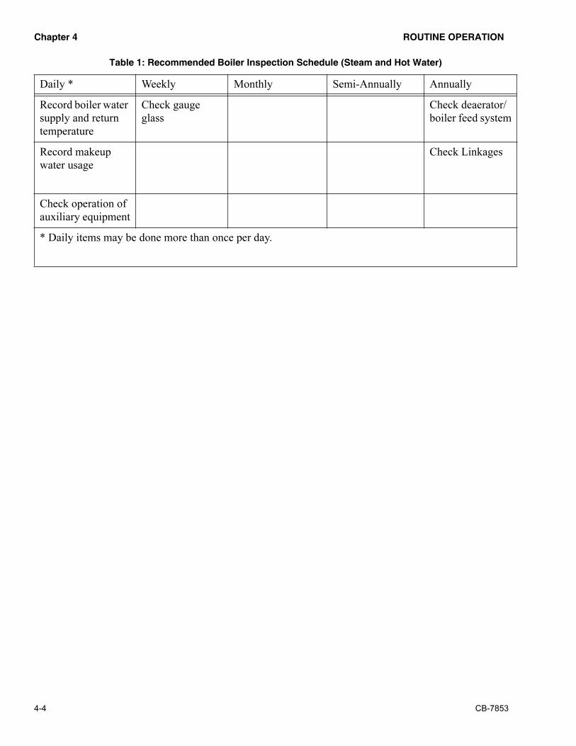
������� �� �������������
4-4 CB-7853
Record boiler water
supply and return
temperature
Check gauge
glass
Check deaerator/
boiler feed system
Record makeup
water usage
Check Linkages
Check operation of
auxiliary equipment
* Daily items may be done more than once per day.
���������������������������������� ����!��" �������#��$����%
Daily * Weekly Monthly Semi-Annually Annually

�� ������������� �������
CB-7853 4-5
�����������������
1. Check water level. An unstable water level can indicate several problems such
as excessive solids or water treatment, contamination from oil, overload or
control malfunction. Ensure there is water in the gauge glass every time you
enter the boiler room. See additional information later in this chapter.
2. Blow down boiler. Blow down the boiler in accordance with the
recommendation of your feedwater consultant. A water quality and chemical
treatment program will dictate frequency of boiler blowdown. See additional
information later in this chapter.
3. Blow down the water level controls to purge the float bowl of possible
sediment accumulation. Operating conditions will dictate frequency of this
check. See information later in this chapter.
4. Check combustion visually. Look at the flame to see if something has changed.
Changes may be an indication that a problem is developing.
5. Treat water according to the established program. Add chemicals and take tests
as outlined by your chemical feedwater consultant. See information later in this
chapter.
6. Record boiler operating pressure or temperature. An excessive steam or water
temperature drop will alert you to excessive loading on the boiler.
7. Record feedwater pressure and temperature. A change in pressure or
temperature may indicate a problem is developing with your feed pump (s),
deaerator or packaged feed system.
8. Record stack temperature. Changes in stack temperatures could indicate the
boiler is sooting, scaling or there is a problem with baffles or refractory.
9. Record oil pressure and temperature. Changes in pressure and/or temperature
could have an effect on combustion in the boiler and could indicate a problem
in the oil regulators or oil heater.
10. Record oil atomizing pressure. Changes in pressure could have an effect on
combustion in the boiler.
11. Record gas pressure. Changes in pressure could have an effect on combustion
in the boiler and indicate a problem in the gas delivery system.
12. Check general boiler/burner operation. Maintaining top efficiency is the
simple and basic reason for having operating personnel. Is anything different
than it was the day before? If so, why?
13. Record boiler water supply and return temperatures. On hot water boilers,
record these temperatures to assist in detecting system changes.
14. Record makeup water usage. Excessive makeup water could be an indication
of system problems in both steam and hot water systems.
15. Check auxiliary equipment. There is a vast difference between “is it running”
and “is it running properly.” Take nothing for granted, as auxiliary equipment
can shut down your operation.

������� �� �������������
4-6 CB-7853
�������������������
1. Check for tight closing of fuel valves. Check to ensure fuel does not flow
through the fuel valve (s) when the burner is shut off.
2. Check fuel and air linkages. Check to ensure that all set screws on linkages are
tight and are securely holding the linkage in place.
3. Check indicating lights and alarms. Check for burned out or loose light bulbs.
Also check to ensure the alarm bell or horn sound on the appropriate shut down
condition.
4. Check operating and limit controls. Check to ensure these controls shut the
burner down at their predetermined set point. Settings should be verified by
checking actual pressures and temperatures on the boiler gauges.
5. Check safety and interlock controls. Check to ensure these controls shut the
burner down at their predetermined set point. Settings should be verified by
checking actual pressures and temperatures on the boiler gauges.
6. Check operation of water level controls. Stop the boiler feed pump and allow
the control to stop the boiler under normal low fire conditions. See your
operating manual for a more detailed procedure. See information later in this
chapter.
7. Check for leaks, noise, vibration, unusual conditions, etc. Checking for these
items is a cost effective way to detect system operational changes. Small
problems can be corrected before they become large problems.
8. Check operation of all motors. By developing a routine, any change in
operation or bearing temperature will usually be caught in time to avoid a
failure.
9. Check lubricating levels. Check levels of any oil bath filters, oil level in air/oil
tank, oilers on pumps, etc. Add oil in accordance with the manufacturer’s
recommendations.
10. Check the flame scanner assembly. Using the appropriate meter, check the
flame signal strength at the program relay flame amplifier. Ensure the scanner
assembly is clean and dry.
11. Check packing glands on all pumps and metering devices. Proper tension on
packing glands will extend life of the equipment.
12. Check gauge glass. Ensure there are no cracks or etching in the glass or leakage
around the packing.
�������������������
1. Inspect burner operation. Do a visual inspection of the pilot flame, main burner
flame throughout the firing range, free movement of linkages and general
burner operation.
2. Analyze combustion. Take the flue gas analysis over the entire firing range,
comparing the combustion analysis and stack temperature readings with
previous month.

�� ������������� �������
CB-7853 4-7
3. Check cams. Inspect the cam springs for scoring, tightness of set screws, free
movement, alignment of cam followers and other related parts.
4. Check for flue gas leaks. Ensure something hasn’t changed in the breeching,
stack or overall system that allows flue gas to be drawn into the boiler room.
5. Inspect for hot spots. Inspect the boiler to ensure no hot spots are developing
on the outside of the boiler. Hot spots can indicate a refractory failure or baffle
failure, which could cause improper gas flow through the boiler or the cooling
lines could be plugged or disconnected.
6. Review boiler blowdown to determine that a waste of treated water is not
occurring. Check water treatment and testing procedures with your feedwater
consultant. See additional information later in this chapter.
7. Check all combustion air supply inlets to the boiler room and burner to ensure
sufficient air is being supplied.
8. Check all filter elements. Clean or replace as needed. On “self-cleaning”
filters, make certain that impurities are flushed or discharged from filter body.
9. Check the fuel system to make certain that strainers, vacuum gauges, pressure
gauges and pumps are properly cared for.
10. Check all belt drives for possible failure. Tighten V-belt sheaves and make
certain that belts operate with proper tension.
11. Check lubrication requirements of all bearing supported equipment. Do not
over-lubricate electric motors.
����������������������
1. Clean low water cutoff (s). Remove the head assembly or probes and inspect
and clean out any sediment or contamination in the column or piping.
Determine why sediment or contamination condition exists. See additional
information later in this chapter.
2. Check oil preheaters by removing the heating element and inspect for sludge
or scale.
3. Repair refractory. Immediately upon opening the fireside areas, give the
refractories an inspection and start repairs as soon as possible. Read and follow
refractory repair instructions.
4. Clean oil pump strainer and filter. Ensure they are not plugged, thus reducing
the flow of the required oil to the burner.
5. Clean air cleaner and air/oil tank. Inspect and clean out any sediment or
contaminat ion. Add oi l in accordance with the manufacturer ’s
recommendations.
6. Check pump coupling alignment. Check alignment of all couplings to ensure
the tolerances are within the manufacturers recommendations.
7. Reset Combustion. The entire combustion process should be carefully
checked, O2 readings taken and necessary burner adjustments made. Make
certain the readings are recorded and used as a basis of comparison for future

������� �� �������������
4-8 CB-7853
tests. Combustion adjustments should only be made by those thoroughly
familiar with all aspects of burner adjustment and combustion.
8. Inspect mercury switches. Inspect mercury switches for contamination, loss of
mercury, and cracked or broken wires. Replace if any of these conditions are
found.
������������������
Note: Annual maintenance should be coordinated with the annual
pressure vessel inspection performed by insurance or government groups.
Establish a firm procedure with all outside inspection groups so that your
equipment will be in a proper state of readiness. As a matter of routine,
establish a procedure using good safety practices whenever a boiler is
taken off the line. Disconnect all power supplies and lock switches in the
off position. Whenever there is more than one boiler connected to a
common header establish a routine procedure of locking the header valve
on any unit that is down for cleaning or inspection, close any flue gas outlet
dampers, and all pieces of equipment required to isolate the boiler.
1. Clean fireside surfaces by brush or use a powerful vacuum cleaner to remove
soot. After the cleaning process and if boiler is to be left open, it is advisable
to spray all fireside surfaces with some type of corrosion preventative.
2. Clean breeching. Inspect breeching and stack and remove any soot build up.
3. Clean waterside surfaces. Remove all handhole and manway plates, inspection
plugs from water column tees and crosses and float assemblies from water
columns. Thoroughly wash all waterside surfaces.
4. Check oil storage tanks. Oil storage tanks should be inspected for sludge and
water accumulation. Keep the tank filled with oil to prevent condensation
during summertime.
5. Check fluid levels on all hydraulic valves. If any leakage is apparent, take
positive corrective action immediately.
6. Check gauge glass for possible replacement. If internal erosion at water level
is noted, replace with new glass and gaskets. On all unattended boilers, the
gauge glass mounting should be of the safety style with stop-checks in case of
glass breakage.
7. Remove and recondition safety valves. Have them reconditioned by an
authorized safety valve facility. The safety valve is an important device yet
possibly receives less attention than any other device. See additional
information later in this chapter.
8. If oil fuels are used, check on the condition of the fuel pump. Fuel pumps wear
out and the annual inspection time is the opportune time to rebuild or replace
them.
9. Boiler feed pumps. Strainers should be reconditioned. Feed pump elements
wear and must be replaced. Sometimes a review of the condensate return
system and chemical feed arrangement will reveal causes of short pump life.
See additional information later in this chapter.

�� ������������� �������
CB-7853 4-9
10. Condensate receivers should be emptied and washed out. Make an internal
inspection, if possible. If the receiver has a make-up valve mounted, it should
be overhauled and checked for proper operation.
11. Chemical feed systems should be completely emptied, flushed and
reconditioned. Metering valves or pumps should be reconditioned at this time.
12. Tighten all electrical terminals. All terminals should be checked for tightness,
particularly on starters and movable relays.
13. Check deaerator or boiler feed systems. Inspect them to ensure they are not
contaminated, corrosion is not taking place and that the lining has not
deteriorated and fallen off. Check all other mechanical aspects of the
equipment. See information later in this chapter.
14. Check linkages. Check to ensure the linkage ball connectors have not worn out.
Worn connectors can cause inconstancy in the linkage movement and result in
unrepeatable excess air levels in the combustion process.
�������������
During operation, there are certain procedures that should be performed by
the operating personnel. The best way to keep track of procedures and to
help remind the operator to perform certain functions is to keep a boiler
room log. For a log to be effective, it must provide a continuous record of
boiler operation and maintenance and record any unusual observations. The
number and frequency of the checks to be performed depend on the type of
boiler room installation. The Hartford Steam Boiler Inspection and
Insurance Company, in their Engineering Bulletin No. 70 “Boiler Log
Program,” explains why a log is desirable, and also points out the various
tests to be performed on the equipment or apparatus. Bulletin No. 70
recommends the various tests to be performed and the frequency of log
entries as follows:
1. Low Pressure Steam and Hot Water Heating Boiler Logs - Weekly Readings
2. High Pressure Power Boiler Log, for relatively small plants that do not have
constant attendance - Twice Daily readings with more frequent checking while
in operation.
3. High Pressure Power Boilers, larger units in large plants - Hourly Readings,
the preferred frequency for all high pressure boilers.
In the interest of accident prevention and safe operating and maintenance
practices, the Hartford Steam Boiler Inspection and Insurance Company and
Cleaver-Brooks Division of Aqua-Chem, Inc., offer without cost or
obligation, copies of the boiler room logs. Consult your Cleaver-Brooks
Representative or write to The Hartford Steam Boiler Inspection and
Insurance Company, One State Street, Hartford, Connecticut 06102-5024.

������� �� �������������
4-10 CB-7853
����������������
Statistics show that by far the largest number of preventable accidents
involve the overheating of a boiler. Most of the occurrences are due to low
water conditions.
The statistics in Chapter 3 (see pages 3-11, 3-12) point out how important it
is to keep the low water cutoff in proper working condition. There are
several ways in which the low water cutoff can be checked.
The most recommended method when the boiler is operating is to shut off
the supply of feedwater to the boiler. If the boiler is equipped with its own
individual boiler feed pump, the pump can be shut off. If more than one
boiler is being supplied from the same pump, then a valve in the feedwater
line to the boiler can be closed. With the supply of water to the boiler shut
off, the water level will slowly drop until it falls to the point where the low
water cutoff mechanism should actuate and shut the burner down. This is
known as an evaporation test. The test should be performed only under close
supervision and when the boiler is operating at low fire conditions. The low
water cutoff should activate before the water disappears completely from
the gauge glass.
When blowing down the gauge glass and the water column, the operator
should carefully observe the action of the water in the glass. When the drain
valve is closed, the water level should recover promptly. If the water level
is slow or sluggish in returning to its normal level, it is an indication there
is some obstruction partially blocking the flow of water into the control
chamber. If the apparent obstruction cannot be cleared up by blowing down,
then the boiler should be shut down and cooled off so the water column float
(or probe) chamber can be opened up and inspected. If there are any mud,
scale, or sediment deposits, they should be removed completely. The float
and linkage should be examined to make sure everything is in good working
order. All of the connecting piping should be inspected and, if necessary,
rodded out to remove any obstructions.
On a steam boiler, the head mechanism of the low water cutoff device(s)
should be removed from the bowl at regular intervals to check and clean the
float ball, the internal moving parts, and the bowl or water column.
In addition and at the same time, remove the pipe plugs from the tees or
crosses to make certain the cross connecting piping is clean and free of
obstructions. Controls must be mounted in a plumb position for proper
performance. Determine that piping is vertically aligned after shipment and
installation and throughout the life of equipment.
A scheduled blowdown of the water controls on a steam boiler should be
maintained.
On a hot water boiler, it is impractical to blow down the low water cutoff
devices since the entire water content of the system would become involved.
In addition, since many hot water systems are fully closed, any loss of water

�� ������������� �������
CB-7853 4-11
will require makeup and additional feedwater treatment that might not
otherwise be necessary. Since the boiler and system arrangement usually
makes it impractical to perform daily and monthly maintenance of the low
water cutoff devices, it is essential to remove the operating mechanism from
the bowl annually or more frequently if possible to check and clean the float
ball, internal moving parts, and the bowl housing. Also check any cross
connecting piping to make certain that it is clean and free of obstruction.
����������������� ��!�
Another extremely important safety check that should be performed is the
testing of all safety and relief valves. How frequently the test should be done
is an extremely controversial subject. Everyone seems to agree that safety
and relief valves should be checked or tested periodically, but very few
agree as to how frequently they should be tested.
The ASME book on “Recommended Rules for Care and Operation of
Heating Boilers,” Section VI, states that the safety or relief valves on steam
or hot water heating boilers should be tested every thirty days. A try lever
test should be performed every thirty days that the boiler is in operation or
after any period of inactivity. With the boiler under a minimum of 5 psi
pressure lift the try lever on the safety valve to the wide open position and
allow steam to be discharged for 5 to 10 seconds (on hot water boilers hold
open for at least 5 seconds or until clear water is discharged). Release the try
lever and allow the spring to snap the disk to the closed position.
An optional method that may be preferred by the owner or operator is to
slowly build up the pressure in the boiler until the popping point of the valve
or valves is reached. As soon as the valve(s) pop, cut back on the firing rate
or shut the burner off and allow the pressure to drop back to its normal
operating range. This procedure should be followed once or twice a year.
The ASME book on “Recommended Rules for Care of Power Boilers,”
Section VII, does not list any specific period of elapsed time between testing
of safety valves. The book does state that all safety valves should be kept in
good working order at all times. The best time for testing the safety valves
or relief valves on power boilers and high temperature hot water boilers
(HTW) is just prior to the shutdown for mandatory inspection. The safety
valves can be tested while operating at low output and throttling the non-
return or boiler stop valve until the lowest set safety valve relieves. Normal
pressure should then be restored by slowly opening the non-return valve.
The valve which relieved may then be gagged and the procedure repeated
until all valves have been checked.
If the boiler is the type where a stop or non-return valve is omitted, close the
prime mover throttle valve and test the valves by raising the pressure by
varying the firing rate. Use the vent or drain valves on the superheaters,
reheaters, or steam piping to provide the minimum flow necessary to
prevent any overheating. Install temperature measuring devices at the
critical points to assure that safe metal temperature limits are not exceeded.
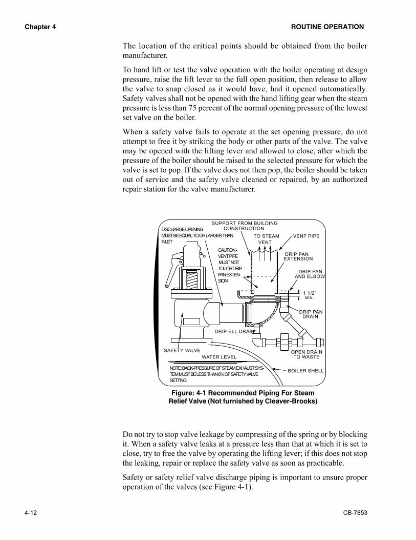
������� �� �������������
4-12 CB-7853
The location of the critical points should be obtained from the boiler
manufacturer.
To hand lift or test the valve operation with the boiler operating at design
pressure, raise the lift lever to the full open position, then release to allow
the valve to snap closed as it would have, had it opened automatically.
Safety valves shall not be opened with the hand lifting gear when the steam
pressure is less than 75 percent of the normal opening pressure of the lowest
set valve on the boiler.
When a safety valve fails to operate at the set opening pressure, do not
attempt to free it by striking the body or other parts of the valve. The valve
may be opened with the lifting lever and allowed to close, after which the
pressure of the boiler should be raised to the selected pressure for which the
valve is set to pop. If the valve does not then pop, the boiler should be taken
out of service and the safety valve cleaned or repaired, by an authorized
repair station for the valve manufacturer.
Do not try to stop valve leakage by compressing of the spring or by blocking
it. When a safety valve leaks at a pressure less than that at which it is set to
close, try to free the valve by operating the lifting lever; if this does not stop
the leaking, repair or replace the safety valve as soon as practicable.
Safety or safety relief valve discharge piping is important to ensure proper
operation of the valves (see Figure 4-1).
DISCHARGE OPENING
MUST BE EQUAL TO OR LARGER THAN
INLET
CAUTION -
VENT PIPE
MUST NOT
TOUCH DRIP
PAN EXTEN-
SION
SUPPORT FROM BUILDING
CONSTRUCTION
VENT
DRIP PAN
EXTENSION
DRIP PAN
AND ELBOW
DRIP PAN
DRAIN
VENT PIPE
OPEN DRAIN
TO WASTE
BOILER SHELL
SAFETY VALVE
DRIP ELL DRAIN
WATER LEVEL
NOTE: BACK-PRESSURE OF STEAM EXHAUST SYS-
TEM MUST BE LESS THAN 6% OF SAFETY VALVE
SETTING.
&�'!���(�����������������'&�� ����
�����)*��+�"���)!��������,����+��(����-�%
TO STEAM
1 1/2”
MIN.

�� ������������� �������
CB-7853 4-13
������������������
During normal operation, maintenance of the burner and controls is
extremely important. If the operation is of such a nature that the boilers are
firing continuously day and night around the clock, most of the maintenance
and repairs that can be made under these conditions are of a minor nature.
Spare oil guns or oil tip and swirlers should be kept cleaned and ready to be
changed as necessary. Keeping a spare oil gun on hand is recommended.
Check all of the valves in the fuel lines, feedwater and steam lines for leaks
and packing gland conditions. Repair, repack and tighten where possible.
Check out burner linkage, jackshafts, drive units, cams, etc. Make sure all
linkage, linkage arms and connections are tight. Lubricate or grease where
required. Note any wear or sloppiness in any of this equipment. If it cannot
be repaired while the boiler is in operation, then it should be noted in the log
book so proper repairs can be made when the boiler is taken out of service.
Operation of the burner should be observed. Is the burner firing properly?
Check the flame shape and combustion. If the burner is not operating
properly, arrangements should be made to have a factory trained
representative work on the burner to correct deficiencies.
Operating controls will normally function properly for long periods of time.
For this reason, some operators become lax in their daily, weekly, or
monthly testing, assuming that normal operation will continue indefinitely.
Malfunctions of controls leads to uneconomical operation and damage and
in most cases, conditions can be traced directly to deficiencies in testing and
maintenance. Here is where use of the boiler room log becomes extremely
useful. When a boiler room log is kept with complete and accurate entries
of operating conditions, the entries can be very helpful in detecting
malfunctions or pinpointing trouble.
Normal and proper operation of a boiler usually follows a distinct pattern.
When readings and tests are made and entered in the boiler room log, these
entries define the pattern. Any deviation from the pattern should be checked
into and, if possible, determined what is causing the change in operating
conditions. Changes in the readings can be gradual over a prolonged period
of time or it can be a sudden change. The gradual change can be something
like a slow increase in the flue gas temperature. An increase in flue gas
temperature can be caused by a loss in heat transfer caused by sooting up of
the boiler on the fireside surfaces, baffle leakage or scale buildup on the
waterside surfaces. A sudden or rapid change in some of the readings can
indicate the fuel-air ratio has changed due to linkage slipping, damper
movement, fuel or air cam adjustment screws changed, or a multitude of
other points that can go out of adjustment.
"���������#�������
Improper water treatment is probably the largest direct cause of boiler
failure. When the boiler feedwater and the boiler water do not receive proper

������� �� �������������
4-14 CB-7853
preparation and treatment, scale and sludge deposits, corrosion and pitting
of the boiler surfaces result. The boiler owner and operator must know that
proper boiler feedwater treatment is an absolute necessity.
Unless the boiler receives water of proper quality, the boiler's life will be
needlessly shortened. The services of a “QUALIFIED BOILER
FEEDWATER CONSULTANT” should be utilized. They would have to
carefully study the plant conditions, materials employed, pumps, lines, heat
users, prevailing water chemistry, etc., to establish a good boiler feedwater
treatment program to accomplish the following:
• Prevent scale and deposits
• Remove dissolved gases
• Protect against corrosion
• Eliminate of carryover
• Correct against embrittlement
• Save on fuel and maintenance
• Achieve highest boiler efficiency
• Minimize of boiler outages
A properly executed boiler feedwater treatment program, along with proper
blowdown procedures, will normally maintain the waterside surfaces in
good condition. If fireside corrosion and erosion conditions are kept to a
minimum, the boiler pressure parts should enjoy a long and useful life.
���������������
When a boiler is generating steam, the feedwater continuously carries
dissolved mineral matter into the unit. The material remains in the boiler
shell or drum, causing an increase in the total solids until some limit is
reached beyond which operation is unsatisfactory. Many difficulties in
boiler operation occur because of excessive concentrations of sludge, silica,
alkalinity, chlorides, or total dissolved solids.
To prevent an excessive accumulation of dissolved and undissolved solids
which will interfere with proper boiler operation, a blowdown program
should be established.
The amount of blowdown or number of times the boiler is blown each day
depends upon the concentration of solids in the boiler water. It is not
possible to include any specific recommendation for blowing down a boiler
because of the difference in the composition of the water that is used for
makeup. Recommendations of the feedwater consultant should be followed
regarding blowdown procedure.
Further, at installations where the condensate returns represent a high
percentage of the total feedwater, it can generally be assumed that the
amount of water that must be blown to waste to properly control the

�� ������������� �������
CB-7853 4-15
concentrations within the boiler may be relatively small in comparison to an
installation at some other location. If no condensate return is available, then
it is necessary to employ some means of establishing the frequency of
blowdowns that are required to eliminate any trouble that would be caused
by steam contamination, or any of the other aforementioned difficulties.
Bottom blowoff valves are primarily meant to be used as drain valves;
however, it is frequently necessary to use the blowoff valves to get rid of
mud and sludge that have settled to the bottom of the boiler shell or drum.
Generally, when boilers are being operated at or near rated capacity, the
circulation is great enough that the mud and sludge do not have much
chance to settle out.
When necessary to blow down the boiler through the blowoff valves (see
Figure 4-2), they should be opened slowly and carefully. The boiler should
be blown down at lower firing rates. Blowoff valves should be closed tightly
after blowdown is completed. The boiler should be equipped with either two
slow-opening valves or one quick-opening valve and one slow-opening
valve piped in series. If the boiler has more than one bottom blowdown
connection, a second quick-opening valve is needed. The following steps
should be taken to blow down a boiler.
1. Open the quick-opening valves (ones closest to the boiler).
2. Open the slow-opening valve.
3. Blow down the boiler for the amount of time specified by your water
treatment consultant by opening and closing the slow-opening valve.
Pay close attention to the water level in the gauge glass. Some loads
&�'!���(.���/��/�*��+����������'�����'�����

������� �� �������������
4-16 CB-7853
require several short blowdown cycles to maintain the proper water
level in the boiler.
4. Close the slow-opening valve.
5. Close the quick-opening valve(s).
6. Open the slow-opening valve again to drain the line between the quick
and slow-opening valves.
7. Close the slow-opening valve again and double check that the shutoff is
tight after the valve has cooled off.
Note:
Note: Never pump the quick-opening valve to blow down the boiler. Such
action could cause water hammer and damage piping and valves. It could
also cause personal injury. Never leave an open blowdown valve
unattended. Remember the valve(s) closest to the boiler must be opened
first.
Blowdown valves on economizers are provided to serve primarily as drain
valves, and this type of equipment should never be blown down in the
ordinary sense while the boiler is in active steaming service, except under
conditions specifically recommended by the manufacturer.
Continuous blowdown or surface blowdown from a location designated by
the boiler manufacturer is generally preferable to intermittent blowdown for
control and solids concentrations. The boiler water may be flashed at one or
more lower pressures and valuable heat recovered.
It is good operating practice just before cutting a boiler into service to give
the boiler a good blowdown. This action helps to start circulation in the
boiler before picking up load.
���������
Deaeration (degasification) is one of the most important steps in boiler
water treatment. Both the low pressure condensate return and the treated
makeup water requires deaeration prior to passage to the boiler feed pumps.
If degasification is carried out external to the boiler, a mechanical process is
usually applied. Such a process depends on the decrease in solubility of
dissolved gases as the water temperature is increased. The principle gases
which are removed by deaeration, because of their contribution to corrosion,
are oxygen and carbon dioxide.
The basic principle of deaeration is to heat the incoming water up to a
temperature that causes the entrained gases to flash out of solution. The best
results in releasing the gases can be obtained with steam at a pressure of not
less than 5 psi (227°F). An atmospheric type of heater will only partially
remove the gases. The column and spray types of deaerators are designed to
operate under a positive pressure of 5 psi or greater. The amount of
maintenance required to keep the average deaerator in operating condition
is very minimal. With a column-type deaerator, there is a tendency to scale
if the is the least amount of hardness in the water going to the deaerator. If

�� ������������� �������
CB-7853 4-17
this scale deposit should build up, it will impede the flow of water through
the packing rings in the column, reducing the effectiveness of the deaeration
process.
The packed column type of deaerator may or may not be cleaned with acid
solution depending on the type of packing in the column. If the column
packing is stainless steel, then acid cleaning could be used. The column as
well as the deaerator tank and all the piping should be thoroughly washed
and back-washed.
The spray type deaerator will generally have a spray valve or spray pipe.
With the spray valve, it may be necessary to check the valve seat for wear
or pitting. The spring compression dimension should be checked and
adjusted to manufacturer's recommendations. If the deaerator has a spray
pipe, then the pipe should be inspected to see if all of the spray holes are
open. If any holes are plugged, they should be opened.
Strainers in all lines should be cleaned at regular intervals determined by
conditions and usage; water gauge glasses should be kept clean and replaced
if necessary. Tighten all packing glands and fittings to eliminate steam and
water leaks. The overflow valve and makeup valve with their associated
level control mechanisms should be checked out. Refer to appropriate
manufacturer’s literature for service recommendations on the particular
components.
Pressure reducing valves feeding steam to a deaerator should be maintained
in accordance with the manufacturer’s recommendations.
#���$�����%��
Soot deposits from firing heavy oil and/or improper combustion on all fuels
can stick on the economizer tubes and cause plugging between the tubes or
between the fins. Soot deposits cut down the efficient operation of the
economizer, cause corrosion from any sulfur in the fuel and increase the
draft losses.
If the economizer is plugged with deposits, they should be removed. If the
deposits are fairly soft, it is quite possible they can be blown out with an air
lance. Hard deposits can best be removed by poking between the tubes. If
the breeching beneath the economizer is built so it can be drained, a jet
stream of water can be used to wash out the deposits. When water is used,
the surfaces must be washed completely to remove all traces of sulfur. The
surfaces should then be dried quickly to prevent any rust or corrosion from
starting. The drying could possibly be done by closing the access doors and
blowing air from the forced draft fan through the unit, or by blowing with
an air lance to dry off the water.
Decreased loads on the boiler result in lower flue gas temperatures, and the
possibility of condensation of moisture from the flue gases. Moisture, with
sulfur compounds from the flue gas, will cause corrosion of the surfaces of
the economizer. Corrosion can be caused by nonuniform flue gas

������� �� �������������
4-18 CB-7853
distribution resulting in pockets of stagnation. The best solution is to operate
the boiler at loads high enough to raise the flue gas temperatures to above
their dewpoint. If this is not a workable solution, then mechanical changes
to the system are recommended. One such change may be to decrease the
flow of boiler feedwater through the economizer using a bypass
arrangement, thus raising the temperature of the flue gas to eliminate the
condensation.
A second option might be the installation of a preheater to raise the
temperature of the water entering the economizer.
A third option might be to provide duct work to allow the flue gas to
completely bypass the economizer during periods of operation at low loads
on the boiler.
The water side of the economizer should be opened up and inspected.
Remove one or more handholes in each header and inspect for scale buildup,
deposits, sediment, etc. Any mud, scale or sediment in the headers should
be cleaned out or washed out. The tubes should be inspected for scale
deposits and plugging. If the tubes are plugged or scaled heavily enough to
impede flow or heat transfer, then the deposit should be removed. The
deposits can be removed either by chemical or mechanical means.
The tubes should also be examined for internal corrosion. Any corrosion of
the internal surfaces is most frequently due to dissolved oxygen in the
feedwater. Precautions must be taken to provide proper conditioning if
difficulty is to be avoided. The water supplied to an economizer should be
properly deaerated and treated by the addition of chemicals.
"���������&�'( )
One of the most important times in the life of a pump is when it is installed.
Proper installation at this time will do more towards pump longevity than
any other one item. The pump should be very carefully leveled, grouted and
aligned before it is piped. Then to make sure the piping has not distorted the
pump housing or pulled it out of alignment, the pump should be checked
again and realigned if necessary.
During periods of operation, there is very little that can be done except to
check it periodically to make sure everything is functioning normally.
Bearing temperatures should be checked. At the same time bearing
temperatures are being checked, the vibration can also be observed. Packing
gland adjustment can be done and, depending on types of lubrication
methods employed, lubrication of the bearing can be done.
Just like other pieces of equipment in a boiler room, the pumps should be
taken out of service on a preplanned schedule for monthly, semi-annual and
annual inspections. At that time the bearings should be checked carefully,
lubricant replaced or added. Flexible couplings should be opened up,
checked for wear and alignment, washed out thoroughly and reassembled
with new lubricant.

�� ������������� �������
CB-7853 4-19
During the same inspection, the pump seals can be inspected and, if
necessary, replaced. If the pump is equipped with mechanical seals and they
are working all right, then probably the best advice is to leave them alone.
If the pumps are equipped with a packing type seal, they should be inspected
and repacked if necessary.
Any suction or discharge strainers should be inspected, opened up and
cleaned. Suction and discharge piping should be checked for proper support,
leaks, etc. If the boiler room log entries indicate that the pump performance
has fallen off appreciably, perhaps overhaul of the pump is advisable. Rotor
wear and increased clearances will affect pump capacity and discharge
pressure. If a major overhaul of the pump is indicated, the pump
manufacturer should be contacted for instructions and recommendations.
"������ ��
In order for any boiler to be able to operate at peak efficiency and as trouble-
free as possible, the fuel handling system must be designed properly and
must also be maintained in top condition at all times.
Full and effective use should be made of manufacturers' instruction books
on operation and maintenance. Of special importance are written procedures
prepared expressly for each installation. Fuel burning equipment should
never be operated below the safe minimum level at which a stable flame can
be maintained. In like manner, operation at rates of fuel input which are
excessive in relation to available air supply should not be tolerated.
Natural gas and fuel oils are the most common fuels used in the currently
popular firetube and watertube packaged boiler. Most of these units are
automatic in their operation with some semi-automatic controls being used.
The gas train in its simplest form for automatic burner boiler unit will
consist of:
1. Manual shutoff valve(s) (or cock).
2. Safety shutoff valve(s). (This valve is an automatic valve that is actuated to
open or close at the direction of the flame safeguard control.)
3. Fuel flow control valve (butterfly valve). (This valve is actuated by the
combustion control system or flame safeguard and modulates to control the
flow of fuel to the burner. It is not a fuel shutoff valve.)
More sophisticated fuel trains to satisfy various code and insurance groups
require additional shutoff valves (manual), dual safety shutoff valves
(automatic) with automatic vent valve in between, high and low gas
pressure interlock switches and also proof of closure switches on one or
more of the automatic shutoff valves.
The entire gas train should be checked carefully to ensure every component
is in good working order. Strainers in the gas line should be opened up and
the strainer baskets cleaned. Inspect the strainer body internally while the
basket is removed. Be sure there is not any lint, dirt, scale, etc., that may be

������� �� �������������
4-20 CB-7853
dislodged with the removal of the basket that could be blown on through the
gas line when the gas pressure is turned on again. Check gas burners for
presence of dirt, lint, or foreign matter. Be sure ports, gas passages, and air
passages are free of obstructions. Linkages, belts and moving parts on
power burners should be checked for proper adjustment. On combination oil
and gas burners, the gas outlets may become caked with carbon residue from
unburned fuel oil after prolonged periods of oil firing and require cleaning.
Lub r i ca t e componen t s i n a cco rdance w i th manufac tu r e r ' s
recommendations. Also check the pilot burner. Clean and inspect the
electrode for igniting the pilot flame. Space and regap the electrode if
necessary. Check the ignition equipment and pilot burner for flame
adjustment and performance.
Note: Under no conditions should fuel train piping (gas or oil) be fastened
to or located near the side casing of an industrial watertube packaged
boiler.
The reason is safety. In the event of a fireside furnace occurrence in an
industrial watertube packaged boiler, the side casing will usually be bulged
outward or torn loose from the force of the occurrence. The gas or oil train
piping fastened to or in close proximity to the casing could be ruptured by
the bulged casing, in which event raw fuel (gas or oil) would be released in
the boiler room.
In the case of an oil burner or combination gas and oil burner, the oil supply
train should be checked out and inspected as diligently as the gas equipment.
Oil burners require periodic maintenance to keep the nozzle and other parts
clean. Check and clean oil line strainers. Inspect and check the nozzle.
Check and clean filters, air intake screens, blowers and air passages. Check
all linkages and belts, and adjust as required. Lubricate components in
accordance with manufacturer's recommendations. Check pilot burners and
ignition equipment for proper flame adjustment and performance.
The oil piping, both suction and return from the storage tanks to the burner,
should be checked over thoroughly, inspecting for leaks, corrosion, and
physical damage.
Where light oil only is being used, the piping and pumping system is fairly
simple. Generally such a system consists of one or more pumps, designed
for pumping the required amount of light oil, suction strainer, discharge
strainer, piping, valves and gauges. Normal maintenance on the pumps
should include checking and repacking or replacing of the seals if necessary.
Check bearings and lubricate if necessary, check coupling alignment and
realign if required, clean and lubricate, if necessary. Any leaks in the piping
or valve packing glands should be tightened or repaired.
�� ������������� �������
CB-7853 4-21
If the burner is designed to burn residual grade fuel oil, then a fuel oil heater
and all of the necessary control components will also need to be inspected
to ensure that the system is in satisfactory working order. Steam and oil
pressure regulators as well as temperature controls should be monitored to
ensure that they function as required and are adjusted to the appropriate
temperature and/or pressure. It is possible for residual fuel oil to foul up the
surfaces of the heater should flows or temperatures go beyond normal
operating limits. The exchanger may become fouled with carbon or sludge,
which will necessitate disassembly and physical cleaning to restore it to its
original performance.

������� �� �������������
4-22 CB-7853
�����

CB-7853 5-1
�"�#$���-
"+$$'&��(.&
When a routine shutdown is scheduled, it should be planned so there is time
to perform certain operations in the shutdown procedure.
1. If the boiler is equipped with sootblowers, and any other fuel other than natural
gas has been fired, the sootblowers should all be operated before taking the
boiler off the line.
All the recommended rules for operating the sootblowers should be followed.
One of the most important rules is that the steam load on the boiler is 70% of
boiler rating or greater. Operation at low load, with its resulting colder furnace
may result in some unburned combustibles escaping from the furnace, and re-
depositing on the tubes or collecting in pockets. Agitation of the combustibles
during sootblowing at low load may result in an occurrence. Therefore, it is im-
portant to have all of the areas of the gas passes thoroughly swept with flue gas,
thus purging any combustible gas from pockets where it may collect.
�������
��������� ��������� ���������
������������� ����� ���������
����� ��� ������ ������� ���
������� ��� ������� ��� ���
������������
������� !"��#$%&'($
5-2 CB-7853
2. After the sootblowing operation is complete, the steam flow from the boiler
should be gradually reduced and the burner run to the low fire position.
3. With the burner in low fire position, blow down the boiler (as explained
previously in Chapter 4) along with the water column, gauge glass, and
feedwater regulator. Turn the burner off in accordance with the burner
manufacturer's instructions. If the boiler is equipped with a flue gas outlet
damper, it should be fully closed to allow the unit to cool slowly.
4. Remove and clean the burner oil gun. Place the fuel supply equipment in
standby condition (for gas, shut main supply cock). Throw the main electrical
switch, and take the feedwater regulator out of service. Hand operate the
feedwater valves to keep the water level above one-half (1/2) gauge glass.
5. When the boiler pressure falls below line pressure, the boiler stop valve should
be closed if the setting has cooled enough to prevent any pressure buildup. If
the boiler is equipped with a non-return valve, the valve should close
automatically when the boiler pressure drops below line pressure. This, of
course, isolates the boiler from other units remaining in service. As the drum
pressure falls below 15 to 25 psi, the manual closing device (handwheel) of the
non-return (if equipped) should be closed and the vent valve on the boiler
opened. This will prevent a vacuum on the boiler waterside, which will loosen
well set gaskets and cause future problems. While there is still a small amount
of steam pressure available, the boiler should be blown down and filled back
to a safe level with freshly treated hot water in preparation for the next startup.
If the boiler is being shut down just for overnight or for the weekend, the
foregoing procedure is generally all that is required. The primary concern is
to make sure there is sufficient water in the boiler. If the boiler is only going
to be shut down overnight, the boiler can be secured and will have pressure
still showing the next morning. When the boiler is insulated well enough to
permit steam pressure to remain overnight, there is no danger of pressures
dropping low enough to start pulling a vacuum. Then the boiler vent valve
can be left closed.
In those instances where the boiler may be left unattended long enough that
the boiler cools down and does start to pull a vacuum, the piping can be
equipped with a vacuum breaker valve. The valve can be installed close to
the top of the steam drum or shell, preferably above the water line. As the
boiler cools down and the condensing of the steam starts to form a vacuum,
the valve permits air to enter the drum and atmospheric pressure will exist
in the drum. One precaution must be taken in such an installation. When
starting up the boiler each time, be sure the boiler vent valve is opened to
evacuate all of the air that has been trapped in the boiler and boiler water.
Up to this point, we have been talking about shutting down the boiler for just
a few hours or a few days. If the boiler is going to be taken out of service for
several weeks or several months, then a different procedure must be
followed.

!"��#$%&'($ �������
CB-7853 5-3
There are two (2) basic methods of laying up a boiler for extended periods
of time. They are wet and dry storage.
If the unit is to be stored for no longer than a month and emergency service
is required, wet storage is satisfactory. Wet storage is not generally
employed for boilers that may be subjected to freezing temperatures.
Several alternative methods may be employed.
1. The boiler to be stored should be closed and filled to the top with chemically
treated feedwater or condensate, to minimize corrosion during standby storage.
Water pressure greater than atmospheric pressure should be maintained within
the boiler during the storage period. A head tank may be connected to the
highest vent of the boiler to maintain pressure above that of atmospheric
pressure.
For short periods of wet storage, the water or condensate in the boiler should
contain approximately 450 PPM of caustic soda and 200 PPM of sodium
sulfite. If the boiler is equipped with a superheater of the drainable type, it can
also be filled with the above described treated water by overflowing from the
boiler.
If the superheater is non-drainable, it should be filled with condensate or dem-
ineralized water containing no more than 1 PPM of dissolved solids. Before in-
troducing the water into the superheater, sufficient hydrazine should be added
to achieve a concentration of about 200 PPM. Sufficient volatile alkali should
also be added to produce a pH of 10. The treated water may be introduced into
the superheater through an outlet header drain until the water flows into the
boiler. When the superheater is filled, close the vents and drains. This quality
of water may also be used in the boiler. If the storage period should extend be-
yond a month, the concentration of hydrazine should be doubled.
2. As an alternative, the boiler may be stored with water at normal operating level
in the drum and nitrogen maintained at greater than atmospheric pressure in all
vapor spaces. To prevent in leakage of air, it is necessary to supply nitrogen at
the vents before the boiler pressure falls to zero as the boiler is coming off the
line. If boiler pressure falls to zero, the boiler should be fired to re-establish
pressure and drums and superheaters thoroughly vented to remove air before
nitrogen is admitted. All partly filled steam drums and superheater headers
should be connected in parallel to the nitrogen supply. If nitrogen is supplied
only to the steam drum, nitrogen pressure should be greater than the
hydrostatic head of the longest vertical column of condensate that could be
produced in the superheater, or a minimum of 5 psi.
3. Rather than maintain the water in the boiler at normal operating level with a
nitrogen cap, it is sometimes preferred to drain the boiler completely, applying
nitrogen continuously during the draining operation and maintaining a pressure
of nitrogen greater than atmospheric throughout the draining and subsequent
storage.
��������

������� !"��#$%&'($
5-4 CB-7853
�������� Dry storage is preferable for boilers out of service for extended periods of
time or in locations where freezing temperatures may be expected during
standby.
The cleaned boiler should be thoroughly dried, since any moisture left on
the metal surface would cause corrosion. After drying, precautions should
be taken to preclude entry of moisture in any form from steam lines, feed
lines, or air.
A moisture absorbing material should be used, such as quicklime, at the rate
of two (2) pounds or silica gel at the rate of five (5) pounds for 30 cubic feet
of boiler volume. It may be placed on desiccant trays inside the drums or
inside the shell to absorb moisture from the air. The manholes should then
be closed and all connections on the boiler should be tightly blanked. The
effectiveness of the materials for such purposes and the need for their
renewal may be determined through regular internal boiler inspections.
We would strongly recommend that large signs be placed in conspicuous
places around the boiler to indicate the presence of moisture absorbing
materials. The message to be conveyed can be as follows:
Note: Moisture absorbing material has been placed in both the fireside and
waterside of this boiler. These materials must be removed before any
water is introduced into the boiler and before the boiler is fired.
For long periods of storage, internal inspections should be performed to
assess the condition of the moisture absorbing materials. Such inspections
should be initiated monthly, unless experience dictates otherwise. The
moisture absorbing material increases in volume as moisture is absorbed,
making it necessary to use deep pans. Fresh material should be substituted
as needed at the time of the inspection.
Alternatively, air dried externally to the boiler may be circulated through it.
The distribution should be carefully checked to be sure the air flows over all
areas.
If the boilers are going to be stored in any place other than a dry, warm
protected atmosphere, then steps should be taken to protect the exterior
components also. Burner components that are subject to rust, such as
jackshaft, linkage, valve stems, moving parts, etc., should be coated with a
rust inhibitor and covered to protect them from moisture and condensation.
Electrical equipment, electronic controls, relays, switches, etc., should be
similarly protected.
Pneumatic controls, regulators, diaphragm or piston operated equipment
should be drained or unloaded and protected so that moisture, condensation,
rust, etc. will not damage the equipment during a long period of storage.
Feedwater lines, as well as blowdown, sootblower, drain lines, etc., should
all be drained and dried out. Valve stems, solenoid valves and diaphragms
should all be protected by lubricant, rust inhibitors, plastic coverings or
sealants.

CB-7853 6-1
�"�#$���/
$"����0��1�+$'&
�&(�
$"��1(�&�1'�
����������� �����������������������
�������������� ������������� ��
�������������������������������������
�����������������������������������
�� ������ ��� � ����������� �����
�� �������� ����������������������
��������������� ��������������
��� ������������� ������������ �
������ ����� �������� � ������
��� �� ����������������������������
����������An act or instance of burning
���������� ����Physics that deals with
the mechanical action or relations of heat
'��� ����� �

������� �� �����������
6-2 CB-7853
��������
Combustion requires three items, heat, fuel and oxygen (see Figure 6-1).
Heat is provided by the pilot. Fuel can be natural gas, propane, oil, coal,
wood or solvents and/or by-products of a process. The third item is oxygen.
By volume, air contains approximately 21% oxygen, 78% nitrogen and 1%
miscellaneous gases.
During the combustion process, we only use the oxygen in ambient air. The
nitrogen is heated by the combustion process and exits the boiler. It has been
found that nitrogen contributes to air pollution. During the combustion
process, a nitrogen molecule will attach to an oxygen molecule and exit the
boiler in the form of Oxides of Nitrogen, which are classified as NOx.
To maintain satisfactory combustion, once it has been started, there are three
requirements: Time - time for the combustion process to take place;
temperature - which comes from the combustion process; and turbulence
- which is the mixing of the air and fuel.
All three must be considered when a boiler and burner combination is
designed. They must also be taken into account when combustion or fuel/air
ratios are set in a boiler.
During the design process of a boiler and burner, the size of the combustion
air fan must be considered. The fan must provide sufficient air in CFM, so
enough fuel can be added to make the full rated capacity of the boiler, plus
a safety margin. The fan must also produce sufficient static pressure to
overcome the pressure drop across the air damper, burner, diffuser and the
combustion gas passes of the boiler. The fan provides the air for combustion
and moves the combustion gases to the outlet of the boiler. The removal of
the combustion gases from the outlet of the boiler to the top of the stack is
a function of the breeching and stack sizing.
If there is a change in the system, after the original start up of new
equipment, care must be taken to ensure the breeching and stack sizes are
sufficient to remove the combustion gases from the boiler. Breeching and
stacks that are too small or too large can create problems.
Stoichiometric or perfect combustion is a term used to describe a condition
when there is the exact amount - molecule for molecule - of air for the fuel
���
����
�����
=
� !"#$�"%�
�"&'()�*"+
��������� ���� �!"#
�"�$�!��"
���%&�����

�� ����������� �������
CB-7853 6-3
attempting to be burned. Perfect combustion can be accomplished under
laboratory conditions; however, it’s not practical to attempt to meet the
condition in a boiler. Stoichiometric combustion is the reference point used
when setting fuel/air ratios in a boiler.
If combustion is set in a boiler and there is high excess air levels or the
oxygen is rich and the fuel is lean, dollars will be spent to heat up the
nitrogen in the ambient air. The heated nitrogen will go out the stack. This
is not very cost effective. There also is the possibility that too much excess
air at a given firing rate could result in unstable fires in the boiler.
Going the other direction, with too low excess air levels or lean oxygen and
rich fuel, there is a different set of problems. The boiler may soot on the
fireside but, more importantly, there may be excessive amounts of CO
(Carbon Monoxide) in the combustion process. CO is unburned fuel and,
under the right conditions, could reignite.
When combustion or fuel/air ratios are set in a boiler, readings must be taken
to determine the O2 levels in the combustion process. O
2 is the total amount
of excess air in the combustion process, above the point of stoichiometric
combustion. There must always be excess air in the combustion process to
account for changes in boiler room conditions and to ensure that combustion
is on the proper side of the combustion curve.
The only method available to determine the O2 level in a boiler is to measure
the combustion gases at the outlet of the boiler. The O2 level cannot be
determined by looking at the flame.
The O2 levels through the entire firing range of the burner, low fire to high
fire, should be tested. The burner manufacturer’s recommendations on
turndown should be followed and the turndown range of the burner should
not be exceeded.
It’s important there is an understanding of what the readings shown on an
instrument refer to when setting combustion in a boiler. Figure 6-2 shows
the relationship between O2 levels, excess air and the products of
combustion for a typical flue gas analysis for natural gas.
One of the products of combustion is CO2 (Carbon Dioxide), which is
shown as a percentage.
Another product of combustion is CO (carbon monoxide) and is shown in
both percentage and parts per million (ppm). The maximum CO level
standardly allowed is less than 400 ppm (1/10 of 1% is 1,000 ppm). The
instruments used today usually record CO in ppm. The maximum CO level
allowed varies across the country.
Instruments today also measure O2 in percent. The percent O
2 recorded on
an instrument equates to percent excess air, i.e. 2% O2 is approximately
10% excess air, 3% O2 is approximately 15% excess air and 4% O
2 is
approximately 20% excess air.
���%&�����

������� �� �����������
6-4 CB-7853
The exact percentage of excess air is a mathematical calculation based on an
ultimate fuel analysis of the fuel being fired. Excess air is the percentage of
air over stoichiometric or perfect combustion (0% O2).
If instrument readings were plotted as shown on the graph in Figure 6-2,
they would provide the following information.
If there was a CO2
reading of 9% (dot A), it could mean the combustion is
on the proper side of the combustion curve and there is an excess air level
of approximately 25%,or it could be on the wrong side of the combustion
curve (dot B), producing CO, which is a dangerous situation. When setting
combustion and only measuring CO2, it's very important to measure for CO
to ensure which side of the combustion curve you are on. That is why most
instrumentation used today measures O2.
From dot “A,” if the fuel input increased without the air increasing or the air
decreases and the fuel input remains constant and the O2 level dropped to
dot “C” (2% O2
) there is still sufficient excess air (10%) above
stoichiometric combustion to be on the proper side of the combustion curve.
However the combustion ratio could result in the boiler sooting.
������������� ������ ����������
�����������������
������������
�
�
�
�
�
��
��
��
�� �� �� �� �� ����� �
���������������� �����
��������'�2�����(!���
����� �� ���������������!���"�
�#���$%��&����'��(���������
�
�
�
���%&�����

�� ����������� �������
CB-7853 6-5
If the problem is not corrected and the fuel continues to increase or the air
decrease, it's possible to get to the point where there is a visible trace of stack
haze, while firing natural gas. This is a very dangerous situation and can
only be controlled through manual action by a qualified boiler operator.
Changes in barometric pressure and ambient air temperature can effect
combustion (see Table 6-1). Typically changes in barometric pressure result
in small changes in excess air levels in the combustion process.
If, for example, combustion is set when the ambient air temperature is 80°F,
the barometric pressure at 29" and an excess air level of 15% excess air or
3% O2 and the barometric air pressure changes to 28", the excess air level
drops to 11%. If the barometric pressure changes to 30" the excess air level
increases to 19%.
However, a 20° or 30° F., change in ambient air temperatures can result in
large changes in excess air levels. Using the same set up point of 80° F
ambient air temperature, 29" barometric pressure and 15% excess air and
the ambient air temperature changes 20° F. the changes in excess air levels
will be greater. A drop in ambient air temperature to 60° F. will result in a
rise in excess air to 20.2% or about a 4% O2.
If the O2 levels are allowed to continue to rise, the boiler efficiency would
be reduced and the possibility of unstable fires in the boiler could exist.
However, when going the other direction and the ambient air goes from 80°
F. to 100° F., the excess air will drop to 9.6% or about a 1.9% O2.
This is still safe because it’s above the point of stoichiometric combustion,
but this condition could result in a soot build up in the boiler. Under this
condition, the CO levels could increase and, if the excess air levels continue
to drop, there could be a dangerous condition.
As the air in the boiler room gets hotter, the density of the air decreases and
results in lower excess air levels. As the air in the boiler room gets cooler,
the air density increases and results in higher excess air levels.
If, through the year, there are large temperature air changes (20° to 30° F)
the combustion or fuel/air ratios should be readjusted several times a year to
keep the boiler operating in a safe and efficient condition. Readjustment
could be done during the spring and fall of the year.
An O2
Trim system could be installed, under the right application, to help
compensate for the varying conditions (refer to page 1-14).
One additional item to be aware of in a boiler room is ventilation air. 10
CFM per boiler horsepower of air available is required in the boiler room, 8
CFM for combustion and 2 CFM for ventilation. If the amount of air is
reduced, it will have an effect on combustion. While the recommendations
are Cleaver-Brooks, local codes may supersede the requirements.
���%&�����

������� �� �����������
6-6 CB-7853
���%&�����
��������� �����������
For a burner originally adjusted to 15% excess air, changes in combustion air temperature,
pressure and humidity will have the following changes in excess air.
��$����� ##�)�!�#���*�"������!
�������������� %��"�����)*��!!��� ��!���� �+ ,)�!!���-
40 29 25.5
60 29 20.2
80 29 15 (setup)
100 29 9.6
120 29 1.1
80 27 7
80 28 11
80 29 15 (setup)
80 30 19
40 31 34.5
60 30 25
80 29 15 (setup)
100 28 5
120 27 -5.5
* Expressed as a percentage of Stoichiometric air required.

�� ����������� �������
CB-7853 6-7
� ������������������ ���
The terms temperature, thermal energy, internal stored energy and heat
are related to a specific law of energy: the Law of Energy Conservation.
The Law of Energy Conservation states: “energy can be neither created
nor destroyed, only altered in form.” In essence, the law states that all
energy that exists must be accounted for.
For example, if a body's temperature decreases, it has lost some of its
energy. Because temperature is a measure of molecular energy, a decrease
in temperature represents a decrease in the molecular energy of a substance.
The energy has not been lost; however, it has been transferred out of the
body in the form of heat. The transfer of heat out of a body causes the
temperature of the body to decrease and the temperature of whatever
surrounds it to increase.
The amount of heat transferred out of a body is equal to the amount of
energy lost by the body. Therefore, all of the energy is accounted for.
The two units commonly used to measure heat are the British Thermal Unit
(Btu) and Calorie (Cal). A Btu is defined as the amount of energy needed to
raise the temperature of one pound of water one degree Fahrenheit.
A calorie is defined as the amount of energy needed to raise the temperature
of one gram of water one degree Celsius. Btu's are used for the examples
throughout Chapter 6.
There is also a unit of measurement for the rate of heat transfer. The rate of
heat transfer, often referred to as thermal power, is measured in units of
Btu's per hour. The rate of heat transfer is the amount of heat transferred into
or out of a body per unit of time.
� ����� ������������� ��� ���� ��������� ���
The addition of heat to a solid at its melting point produces a change of
physical state instead of a rise in temperature. Thus, heat added to ice at 32°
F. causes it to change to water at 32° F. When added heat produces a change
of state instead of a change in temperature, it is called latent (hidden) heat.
The amount of heat required to melt a unit mass (or weight) of a substance
at its melting point is called its latent heat of fusion. Conversely, if a unit
mass of water at 32° F. is sufficiently cooled so the heat is removed from it,
then ice would form and its temperature will measure 32° F.
As the water changes state, there is no change in temperature. The process
is called the latent heat of fusion. In order to change one pound of water at
32° F. to ice at 32° F., we must remove 144 Btu's of heat from the water, (see
Figure 6-3).
When heat is added to a liquid at its boiling point, a change in physical state
is produced rather than a change in temperature. The amount of heat
required to change a unit mass of water to steam at its normal boiling point
is known as its latent heat of evaporation. Conversely, if a unit mass of
'�)*�)�"%�
� !#&",$+�&*�)

������� �� �����������
6-8 CB-7853
steam at 212° F. is sufficiently cooled so that the heat is removed from it
then water will form and its temperature will measure 212° F. This is known
as the latent heat of condensation. Figure 6-4 shows the energy required to
change water into steam and steam into water.
Evaporation or vaporization occurs when molecules of the liquid phase,
because of their internal kinetic energy, bounce out of the liquid phase into
the gaseous or vapor phase. Vaporization of molecules from the liquid phase
is known as evaporation; vaporization from the solid phase is known as
sublimation. Since the rate of evaporation and sublimation depends on the
energy of the particles, undergoing the change depends upon their
temperature. Evaporation and sublimation occur more rapidly at higher
t empe ra tu r e s and more s l owly a t l ower t empe ra tu r e s .
The dashed line in Figure 6-5 is referred to as the saturation curve. At the
top of the curve is a point called critical point. In the case of water, the
1 Pound
of Water
at 2120
1 Pound
of Steam
at 2120
F.
970 Btu’s
Receives
Forms
Forms
Gives UpF.
��������. ���(��/����0#"�1��� �����"#��!�" 2
��������3 ���(��/����0#"�1��� �����"# 4��"����" "��" 0� !���" 2
1 Pound
of Ice
at 320
1 Pound
of Water
at 320
F.
144 Btu’s
Receives
Forms
Forms
Gives UpF.

�� ����������� �������
CB-7853 6-9
critical point occurs at a pressure of 3206 psia and a temperature of 705° F.
At the critical point, the latent heat of vaporization is zero, which means that
any additional heat added can only result in a superheated vapor. A
superheated vapor is a vapor whose temperature is higher than its boiling
temperature.
The points on the saturation curve, on the left side of the critical point,
represent liquids at the boiling temperature for a given pressure. The points
on the right side of the critical point represent vapor at the boiling
temperature. Horizontal lines connecting the two points represent the latent
heat of vaporization for various pressure conditions.
The boiling temperature of water is different at different pressures. For
example, at atmospheric pressure, the boiling temperature of water is 212°F.
At pressures lower than atmospheric pressure, the boiling temperature of
water decreases, because the molecules of water are not forced as closely
together. This means that the water molecules can escape the body of water
more easily, which makes it easier for steam to form. On the other hand, at
pressures above atmospheric, the boiling temperature of water increases,
because the water molecules are packed so closely together that they require
a temperature higher than 212° F. before they are able to escape the body of
water.
The graph in Figure 6-5 can be used to explain the relationship of pressure
and temperature to the boiling point of water. The line representing
atmospheric pressure on the graph is used as a reference. As indicated on the
graph, water at a pressure of 100 psig boils at approximately 338° F. The
�����������
���������������
�� ����������������
�����������
�������� �!����"������
##$�
�%�
����
�%�
�&��
�%�
#�� �%�
!������'����(�����)��%*�#��&������
���������������������
��������5������" !���"#*��!!���� 0
������������"���%"��� �*"� �"#6����

������� �� �����������
6-10 CB-7853
latent heat of vaporization at 100 psig is about 881 Btu's per pound, which
means that the water vaporizes at a higher temperature above atmospheric
pressure. It also takes less heat to make it change completely to steam. The
reason is that the water molecules move more rapidly at higher
temperatures, so it takes less heat to change the water into steam.
Similarly, at a vacuum of 20 inches of mercury, water boils at about 162° F
and the latent heat of vaporization is about 1001 Btu's per pound, which
means that water vaporizes at a lower temperature, but it takes more heat to
make it change completely to steam.
�� ������������� �������� � � �� ������! �������� ��
"�����
Whether a substance exists as a solid, liquid or gas (water vapor), depends
on its temperature, its heat content, and on the pressure to which it is
subjected. Also the temperature of a substance depends on its heat content
and its thermal capacity. As a confirmation of how these factors are related
to the absorption and transfer of heat, consider the changes of state that
occur and the work required to effect these changes when water is raised
from 0° F to 300° F., see Figure 6-6.
The two terms, sensible heat and latent heat, are used to define heat as the
water passes through the temperature range 0 - 300° F. Sensible heat is heat
that can be felt and will change the temperature of the substance absorbing
it. The flow of heat from one substance to another is normally reflected in
the temperature changes of each substance - the hotter substance becomes
cooler, the cooler substance becomes hotter.
When the flow of heat is reflected in a temperature change, sensible heat has
been added to or removed from the substance. When the temperature is
reached at which heat added or subtracted does not cause further change in
temperature (as at the freezing or boiling points), a change in state takes
place with the addition or subtraction of heat.
The heat necessary to cause one pound of a substance to change its state at
the boiling or freezing temperature is known as latent heat; in changing
from a liquid to solid or vice versa, it is known as the latent heat of fusion.
In changing a liquid to a gas, the heat necessary is known as the latent heat
of evaporation and, in changing from a gas to a liquid, it is known as the
latent heat of condensation. The latent heat of fusion of water at 32° F. is
144 Btu per pound (freezing or boiling), and the latent heat of evaporation
(or condensation) at 212° F. is 970 Btu per pound.
Heat is the flow of thermal energy. Adding or removing heat provides a
temperature differential to allow energy to flow from one substance to

�� ����������� �������
CB-7853 6-11
another. Sensible heat and latent heat are two different kinds of effects that
can be produced by heat, but not two different kinds of heat. Three physical
states of all matter are solid, liquid, and gas (or vapor).
The physical state of a substance is closely related to the kinetic energy of
its molecules. When the flow of heat to a substance is not reflected in a
temperature change, the energy is used to increase the kinetic energy of the
molecules and thus to change state. Latent heat is the energy price that must
be paid for a change of state from a solid to a liquid or from liquid to a gas.
Sensible
Heat
F.
F.
F.
F.
F.
F.
Sensible
Heat
Latent
Heat Of
Fusion
Sensible
Heat
Latent Heat
Of Vaporization
(Or Latent Heat
Of Condensation)
18014416 42970
300
212
200
100
32
0
0
0
0
0
0
0
Btu Per Pound Of Water
Figure 6-6.
Temperature - Heat Diagram for 1 lb
of water at atmospheric pressure.
The energy price is repaid when the substance changes back from gas to
liquid or from liquid to solid. Heat flows from the substance during these
changes of state.
Figure 6-6 shows the relationship between sensible heat and latent heat for
water at atmospheric pressure. The same kind of chart could be drawn for
other substances; however, different amounts of thermal energy would be
involved in the changes of state.

������� �� �����������
6-12 CB-7853
Starting with one pound of ice at 0° F., 16 Btu's are required in order to raise
the temperature of the ice to 32° F. To change the pound of ice at 32° F. to a
pound of water at 32° F., 144 Btu's (the latent heat of fusion) must be added.
There will be no change in temperature while the ice is melting.
After the ice has melted, the temperature of the water will be raised as
additional heat is applied. If 180 Btu's - that’s one Btu for each degree of
temperature between 32° F. and 212° F. - the temperature of the water will
be raised to the boiling point. To change the pound of water at 212 ° F. to
one pound of steam at 212° F., 970 Btu's (the latent heat of vaporization)
must be added.
After the water has been converted to steam, the addition of more sensible
heat will cause an increase in the temperature of the steam. Adding an
additional 42 Btu's to the pound of steam at 212° F. will cause the steam to
superheat to 300° F.
The same relationship applies when heat is being removed. The removal of
42 Btu's to the pound of steam at 300° F. will cause the temperature to drop
to 212° F. As the pound of steam at 212° F. changes to a pound of water at
212° F., 970 Btu's are given off. When a substance is changing from a gas
or vapor to a liquid, latent heat of condensation is given off. Notice that the
latent heat off condensation is exactly the same as the latent heat of
vaporization.
The removal of another 180 Btu's of sensible heat will lower the temperature
of a pound of water from 212° F. to 32° F. As a pound of water at 32°F.
changes to a pound of ice at 32° F., 144 Btu's are given off without any
accompanying change in temperature. Further removal of heat causes the
temperature of the ice to decrease.
Figure 6-6 shows that it only takes 16 Btu's to raise the temperature of one
pound of ice from 0° F. to 32° F. - that’s only 1/2 Btu for each degree of rise
in temperature. This is similar to the Btu's needed to raise the temperature
of the steam (superheated) 88° F. - 42 Btu. However, it takes one Btu (on the
average) to raise the temperature of the same amount of water 1° F. This
difference occurs because the specific heat of water is about twice the
specific heat of ice and also steam.
# ����������$���
The basis of a firetube boiler rating is the boiler horsepower. This is defined
as the evaporation of 34.5 pounds of water per hour into dry saturated

�� ����������� �������
CB-7853 6-13
steam. The steam is from a water temperature of 212° F., and the steam is at
212° F. (0 psig) ( see Table 6-2).
The latent heat of a pound of steam is 970 Btu/Pound. Therefore, 34.5
Pounds/Hour/Horsepower times 970 Btu/Pound of steam equals 33,472
Btu/Hour per Boiler Horsepower.
� ��������� ��� ���
Assume that we have a 100 horsepower boiler which has an output of 3,450
pounds of Steam/Hour from and at 212° F. This is equal to an output of
3,347,200 Btu/Hour. The boiler is burning 4,184,000 Btu/Hour of natural
gas and is transmitting 80% of the heat to the water.
If the feedwater is not 212° F., some of the Btu/Hour will be required to add
sensible heat or heat the liquid to get the water up to 212° F.
When making steam at pressures above (0) psig, the boiling temperature
rises. This means additional Btu/Hour of sensible heat must be added to get
from 212° F. up to the higher boiling temperature. The result is part of the
required energy is used to add sensible heat and part of it is used to vaporize
the water.
For example, a 100 horsepower boiler has an output of 3,450 pounds of
Steam/Hour from and at 212° F., or 3,347,200 Btu/Hour. Assume a
feedwater temperature of 100° F. (which is not recommended) and an
operating pressure of 10 psig.
At 10 psig, the boiling temperature equals 240° F., 240 minus 100 equals
140 Btu/Pound which must be added to the 100° F. feedwater to bring it up
to 240° F.
Now, at 10 psig, the latent heat equals 953 Btu/Pound; therefore 953 Btu
must be added to each pound of water at 240° F. in order to vaporize it.
Feedwater at a temperature of 100° F., must receive a total of 1093 Btu’s per
pound of water (140+953) in order to convert to steam at a pressure of 10
pisg.
Therefore, the rated output of 3,347,200 Btu/Hour divided by 1093 Btu per
pound equals an output of 3062 pounds of Steam/Hour with the given
conditions. Note: 3062 Pounds/Hour compared to the rated output of 3450
Pounds/Hour from and at 212° F. Dividing the rated 3450 by the 3062,
equates to 1.12, which is called the factor of evaporation.
If the requirement was 3450 pounds of Steam/Hour, to meet the load
demand, a minimum of a 112 Horsepower Boiler would be required to meet
the demand under the given conditions (100° F., 10 psig operating pressure).
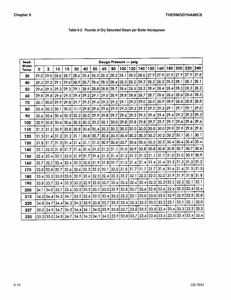
������� �� �����������
6-14 CB-7853
����������� ����� ��������������������������� ������ ���� ���

�������
CB-7853 -1
�����������
Following is an explanation of the abbreviations,
acronyms, and symbols used in this guide.
AC Alternating Current
AR Automatic Reset
ASME American Society of Mechanical Engineers
ASTM American Society of Testing and Materials
BHP Boiler Horsepower
BTU British Thermal Unit
°C Degrees Celsius
CFH Cubic Feet per Hour
Cu Ft Cubic Feet
CFM Cubic Feet Per Minute
DC Direct Current
°F Degrees Fahrenheit
FM Factory Mutual
FS Flame Safeguard
ft Feet
GPM Gallons per Minute
Hd Head
Ht Height
HTB High Turndown Burner
Hz Hertz
In H2O Inches of Water
IRI Industrial Risk Insurance
Lb Pound
LE Low Emission
LWCO Low-Water Cut-Off
MM Million
MFD Micro-Farad
MR Manual Reset
NEC National Electric Code
No. Number
pH Measure of the degree of acid or base of a solution
P/N Part Number
PPM Parts Per Million
PR Program Relay
psi Pounds Per Square Inch
SAE Society of Automotive Engineers
scfh Standard Cubic Feet per Hour
T Temperature
TC Temperature Control
TI Temperature Gauge
UL Underwriter’s Laboratories
V Volt
WC Water Column
WSI Watts Per Square Inch