Boat Lift Controller with Remote - downloads.deusm.comdownloads.deusm.com/designnews/GF-262.pdf ·...
12
Boat Lift Controller with Remote Dick Bipes -- [email protected] Overview At my lake home I have a Shore Station boat lift to lift my boat out of the water when it is not in use. The lift has a manual crank and wheel, which can be quite tedious to operate. I added a Lift Mate Universal motor from Shoreline Industries to crank the wheel for me.
Transcript of Boat Lift Controller with Remote - downloads.deusm.comdownloads.deusm.com/designnews/GF-262.pdf ·...
Boat Lift Controller with Remote Dick Bipes -- [email protected]
Overview At my lake home I have a Shore Station boat lift to lift my boat out of the water when it is not in use.
The lift has a manual crank and wheel, which can be quite tedious to operate. I added a Lift Mate Universal motor from Shoreline Industries to crank the wheel for me.
Boat Lift Controller with Remote
Dick Bipes Page 2
This type of lift and lift motor is very common in the lakes area. The motor works well, but it uses a momentary switch to run it, so you have to stand and hold the switch for the 2-3 minutes that it takes to raise and lower the lift. I wanted automatic operation and remote control. Lift remotes are commercially available – even Shoreline offers one. But none that I could find had the specs that I wanted at a reasonable price.
Design
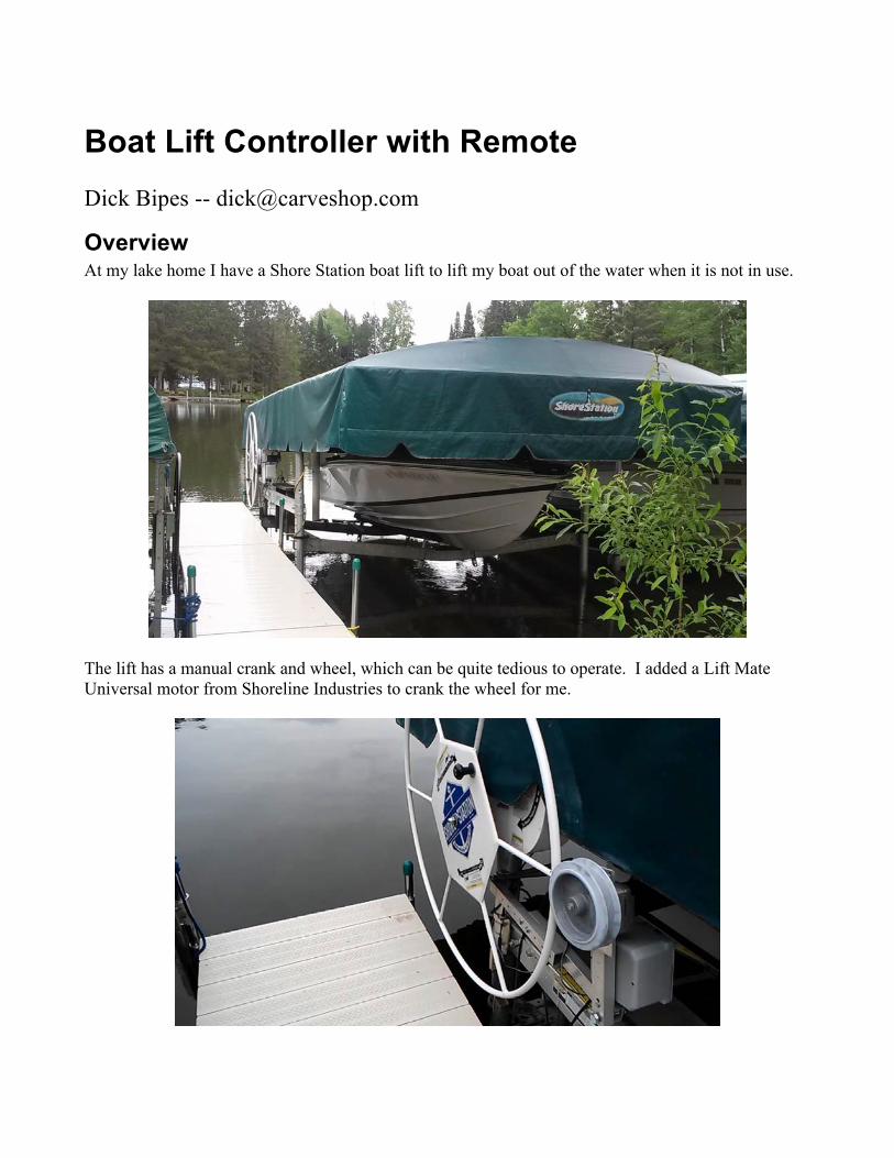
Remote For extended range, a remote that utilizes super heterodyne technology is desired. From a security standpoint, rolling code technology is also desirable. The cheapest remotes with these characteristics can be found in remote car starters that include keyless entry. (Note that almost all keyless entry only systems have limited range, and are not as desirable.)
While not directly suitable for lift control, these remote car starter systems can be adapted with some additional circuitry. I purchased a remote car starter on eBay for $45 with shipping.
Controller I was working up a relay control circuit to adapt this remote for lift use, but quickly realized that it would be too complex. I had previously done a couple of microcontroller projects, so I thought about using a microcontroller for this project. But I decided that an industrial PLC (Programmable Logic Controller) was just what I needed. PLCs can be programmed it in Ladder Logic to mimic relays. In fact, Ladder Logic makes it easier for people familiar with relay logic to make the transition to microcontrollers. I found that Triangle Research International offered a relatively inexpensive PLC which met my needs, so I ordered a Starter Kit for under $100. The key chain remotes from the car starter that I used have five buttons (four on the face and one on the side). For this application, only three buttons are used: * The “Unlock” button corresponds to “lift down”. * The “Lock” button corresponds to “lift up”. * The “Truck Open” button toggles the auxiliary lighting on and off.
Boat Lift Controller with Remote
Dick Bipes Page 3
The PLC converts the outputs of the remote car starter/keyless entry to the appropriate lift control circuitry. The momentary lock/unlock outputs are converted to lift down or up functions. The PLC also interprets the pushing of any button on the remote as a panic stop. The PLC accepts limit switches to automate operation. A magnetic reed switch signals full up. A float switch signals lift down. The float switch automatically compensates for varying lake water levels. I used a float switch from SJE-Rhombus which is specifically tailored for small signal control circuitry. An auxiliary power outlet is toggled on and off by the trunk unlock button. I connect this to some green rope lights strung around the inside of my green canopy. (Very handy for coming home late after July 4th fireworks on the lake!) In addition to the remote car starter and PLC, a few components such as relays, connectors, and cables were needed for this project
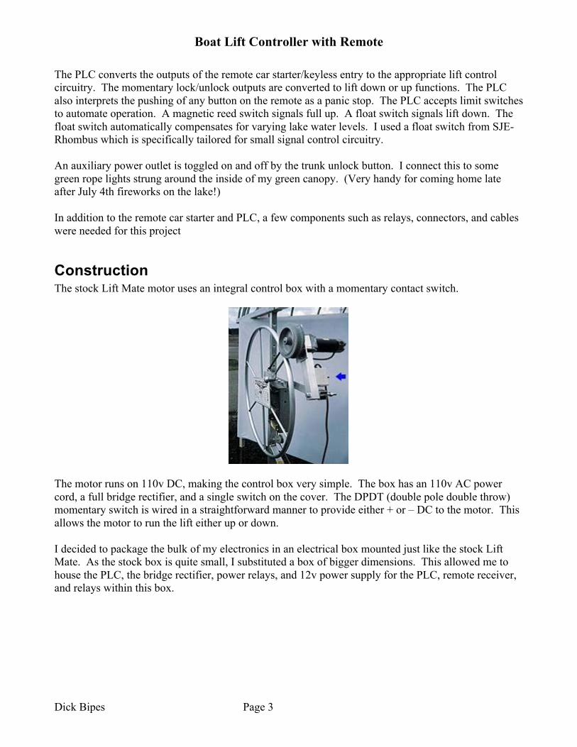
Construction The stock Lift Mate motor uses an integral control box with a momentary contact switch.
The motor runs on 110v DC, making the control box very simple. The box has an 110v AC power cord, a full bridge rectifier, and a single switch on the cover. The DPDT (double pole double throw) momentary switch is wired in a straightforward manner to provide either + or – DC to the motor. This allows the motor to run the lift either up or down. I decided to package the bulk of my electronics in an electrical box mounted just like the stock Lift Mate. As the stock box is quite small, I substituted a box of bigger dimensions. This allowed me to house the PLC, the bridge rectifier, power relays, and 12v power supply for the PLC, remote receiver, and relays within this box.
Boat Lift Controller with Remote
Dick Bipes Page 4
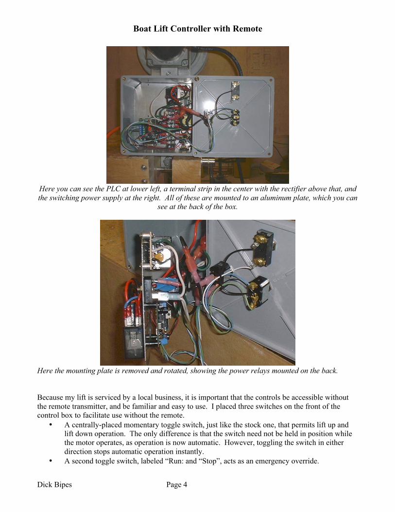
Here you can see the PLC at lower left, a terminal strip in the center with the rectifier above that, and the switching power supply at the right. All of these are mounted to an aluminum plate, which you can
see at the back of the box.
Here the mounting plate is removed and rotated, showing the power relays mounted on the back. Because my lift is serviced by a local business, it is important that the controls be accessible without the remote transmitter, and be familiar and easy to use. I placed three switches on the front of the control box to facilitate use without the remote.
• A centrally-placed momentary toggle switch, just like the stock one, that permits lift up and lift down operation. The only difference is that the switch need not be held in position while the motor operates, as operation is now automatic. However, toggling the switch in either direction stops automatic operation instantly.
• A second toggle switch, labeled “Run: and “Stop”, acts as an emergency override.

Boat Lift Controller with Remote
Dick Bipes Page 5
• A third momentary pushbutton switch turns the canopy lighting on and off. These three functions are also operable via the remote as described in the overview.
Front panel. The top cord is to the motor, the center is power in, and the lower orange cord is to the canopy lighting. At the lower right you can see one of the two connectors for the limit switches. A connector for the radio remote is on the bottom. These allow the entire assembly to be removed for the off season, leaving the limit switches on the lift. The radio remote receiver is housed separately, largely to avoid RF (radio frequency) interference from the electrically noisy Lift Mate motor. I used a water-resistant aluminum box, into which I placed the car starter control module and radio receiver. I drilled holes in this box at either end. At one end, the antenna for the receiver protrudes through a grommet; at the other end, a cable to the control box. The receiver is mounted up under the canopy, away from the motor and control box.

Boat Lift Controller with Remote
Dick Bipes Page 6
Radio receiver.
Schematics
Lift Mate Electronics The stock Lift Mate electronics is pretty straightforward.
Lift Mate schematic
AC power is rectified and applied to the motor in one polarity when the momentary switch is held in one direction and reversed polarity when the motor is held in the reverse direction.
Lift Controller with Remote Electronics The remote car starter package that I used includes a control unit, an extended range receiver, a status LED, a valet switch, and four wiring harnesses. In this application, much of this is not needed and can be discarded. All that is needed is the control unit and extended range receiver. The receiver plugs into the control unit with a supplied cable. I made only 5 connections to the control unit: power, ground, unlock, lock, and trunk. The latter three connections are outputs, and in their default configuration act just like momentary switches to ground.
Boat Lift Controller with Remote
Dick Bipes Page 7
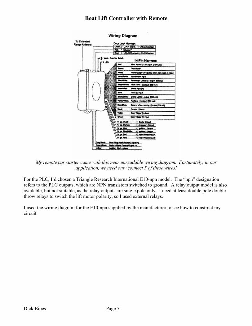
My remote car starter came with this near unreadable wiring diagram. Fortunately, in our
application, we need only connect 5 of these wires! For the PLC, I’d chosen a Triangle Research International E10-npn model. The “npn” designation refers to the PLC outputs, which are NPN transistors switched to ground. A relay output model is also available, but not suitable, as the relay outputs are single pole only. I need at least double pole double throw relays to switch the lift motor polarity, so I used external relays. I used the wiring diagram for the E10-npn supplied by the manufacturer to see how to construct my circuit.

Boat Lift Controller with Remote
Dick Bipes Page 8
E10-npn PLC wiring diagram from the manufacturer
The radio receiver outputs, which are switches to ground, match exactly the inputs of the E10-npn. I connected these directly. I also wired the panel switches in parallel so that I and the service company personnel can operate the lift without the remote. My up and down position limit switches are also simple switches to ground. The Up switch is a magnetic reed relay, with the activating magnet attached to the moving boat cradle. The Down switch is a low-voltage float switch. My lake is actually a reservoir, and the water level does vary over the season. A float switch ensures that the cradle will stop at the correct position regardless of water level. It is desirable to have the cradle touching the boat slightly when lowered, so that the boat does not float free on its own, but rather can be gently powered off and onto the lift. As the PLC inputs are low voltage and low current, safety in the case of a short or exposed wire is not an issue. (Note that a short on the limit switches will cause operation to stop, which is a good fail safe mode.) In place of the original momentary DPDT switch, I substituted a pair of relays that are controlled by the PLC. I choose relays with 12v coils to match the PLC. They are wired as the loads are indicated in the diagram. I used 4 pole relays, with an extra set of contacts wired so that only one relay of this pair may be activated at any time. This keeps the excitement down if I make a PLC programming error. I added a third relay to control canopy lighting. A run/stop switch wired in line with the lift motor allows for a fail-safe shutoff or panic stop for safety. Here’s my completed circuit:

Boat Lift Controller with Remote
Dick Bipes Page 9
Lift Controller with Remote schematic
Programming
Relay logic Before describing the PLC programming, I’ll start by describing the type of relay logic I first considered. This will lead right into the Ladder Logic design. The first task in this design is to convert the momentary pulsed output of the radio receiver to a steady-on output to run the lift motor. Also needed is a way to stop the motor when the lift reaches the full up or down position. Since a relay is needed to safely switch the 110v rectified AC power, a standard solution to the design problem is to use a relay with an extra set of contacts to latch the relay on once it is activated. In the diagram, the Up switch is a normally open pushbutton switch or, in the case of the radio controller I’m using, a transistor momentarily switched to ground. When activated, current flows from the battery (or power supply) through the relay coil, the normally-closed limit switch, and the pushbutton or transistor to ground, activating the relay. As the relay activates, the second set of contacts close, in parallel with the Up switch. The Up switch can now be released and the relay and lift motor will stay activated. (I have not illustrated the lift motor connections for simplicity.) When the upper limit of lift travel is reached, the limit switch opens, breaking the circuit and stopping the motor.

Boat Lift Controller with Remote
Dick Bipes Page 10
Simple relay design solution for lift motor control
This circuit will work, but it has many shortcomings:
• The only way to stop the lift is at the end of travel. There is no way to stop it part way. • I’d like to be able to stop and restart the lift by remote control, in a simple, intuitive way. For
example, push the Lock (up) button the remote a second time. • For added safety, I’d like the lift to stop even if the Unlock (down) button is pushed. • The limit switches are normally closed, meaning a short in the wiring would cause the lift to
keep running. The circuit can be modified to address the shortcomings, but it would get quite complex and require lots more relays.
Ladder Logic Let’s start by taking a look at a Ladder Logic design that mimics the basic control circuit.
Boat Lift Controller with Remote
Dick Bipes Page 11
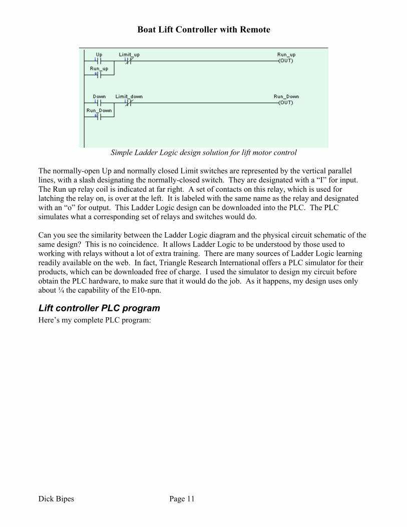
Simple Ladder Logic design solution for lift motor control
The normally-open Up and normally closed Limit switches are represented by the vertical parallel lines, with a slash designating the normally-closed switch. They are designated with a “I” for input. The Run up relay coil is indicated at far right. A set of contacts on this relay, which is used for latching the relay on, is over at the left. It is labeled with the same name as the relay and designated with an “o” for output. This Ladder Logic design can be downloaded into the PLC. The PLC simulates what a corresponding set of relays and switches would do. Can you see the similarity between the Ladder Logic diagram and the physical circuit schematic of the same design? This is no coincidence. It allows Ladder Logic to be understood by those used to working with relays without a lot of extra training. There are many sources of Ladder Logic learning readily available on the web. In fact, Triangle Research International offers a PLC simulator for their products, which can be downloaded free of charge. I used the simulator to design my circuit before obtain the PLC hardware, to make sure that it would do the job. As it happens, my design uses only about ¼ the capability of the E10-npn.
Lift controller PLC program Here’s my complete PLC program:
Boat Lift Controller with Remote
Dick Bipes Page 12
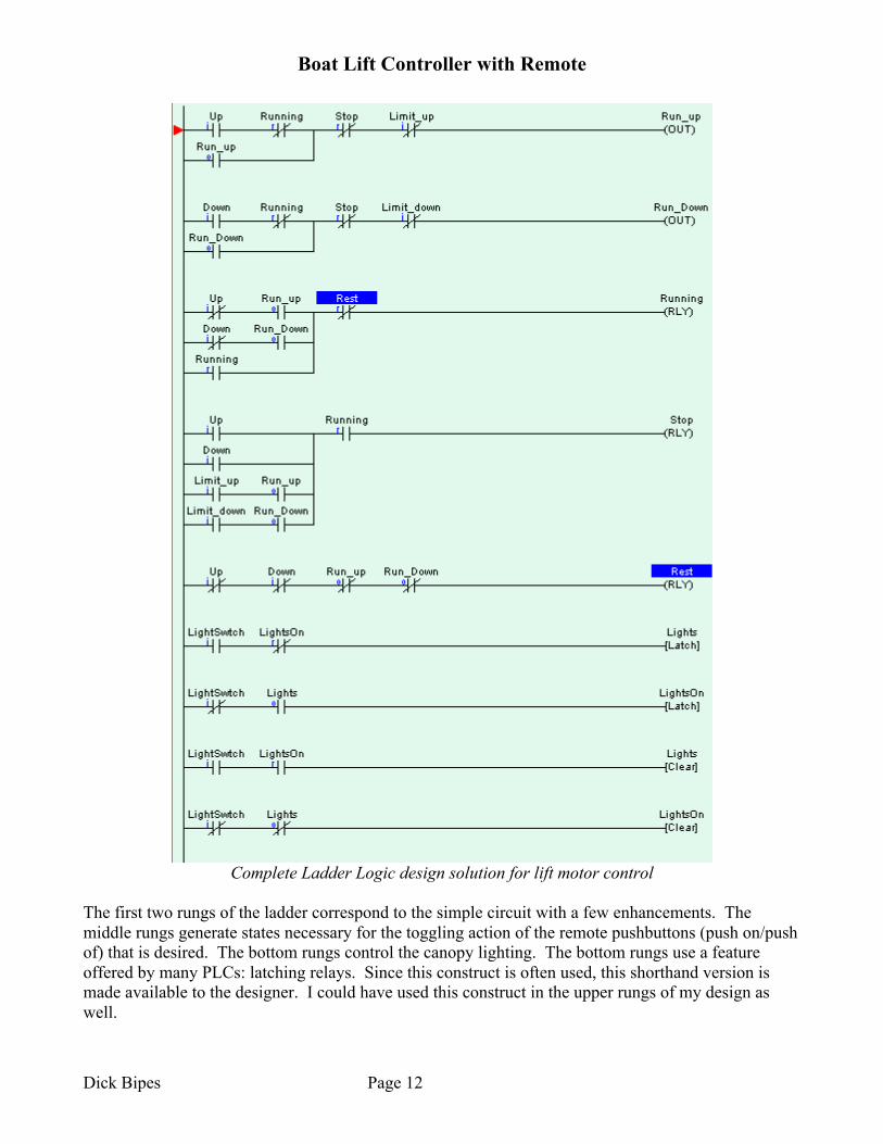
Complete Ladder Logic design solution for lift motor control
The first two rungs of the ladder correspond to the simple circuit with a few enhancements. The middle rungs generate states necessary for the toggling action of the remote pushbuttons (push on/push of) that is desired. The bottom rungs control the canopy lighting. The bottom rungs use a feature offered by many PLCs: latching relays. Since this construct is often used, this shorthand version is made available to the designer. I could have used this construct in the upper rungs of my design as well.