BLUE ORIGIN MANUFACTURING ANNEX BUILDING · blue origin manufacturing annex building specifications...
255
BID DOCS & SPECIFICATIONS set no. BLUE ORIGIN MANUFACTURING ANNEX BUILDING Project Manager: CLW ENGINEERING, LLC Civil: MORGAN & ASSOCIATES, INC. Architect: ARCHITECTS RZK, INC. Mechanical/Plumbing: CEG ENGINEERING GROUP Electrical: PILO ENGINEERING Structural: NOBLE STRUCTURAL GROUP, INC. Pre-Eng. Building: BREVARD CONSTRUCTORS Environmental: NELSON ENGINEERING COMPANY Contractor: W & J CONSTRUCTION CORPORATION Permitting: SPACE FLORIDA RZK# 2015.28 ISSUE DATE: JUNE 30, 2016
Transcript of BLUE ORIGIN MANUFACTURING ANNEX BUILDING · blue origin manufacturing annex building specifications...

BID DOCS & SPECIFICATIONS
set no.
BLUE ORIGIN
MANUFACTURING ANNEX BUILDING
Project Manager: CLW ENGINEERING, LLC Civil: MORGAN & ASSOCIATES, INC.
Architect: ARCHITECTS RZK, INC.
Mechanical/Plumbing: CEG ENGINEERING GROUP Electrical: PILO ENGINEERING
Structural: NOBLE STRUCTURAL GROUP, INC. Pre-Eng. Building: BREVARD CONSTRUCTORS
Environmental: NELSON ENGINEERING COMPANY
Contractor: W & J CONSTRUCTION CORPORATION Permitting: SPACE FLORIDA
RZK# 2015.28
ISSUE DATE: JUNE 30, 2016

TABLE OF CONTENTS - 1 6120
BLUE ORIGIN MANUFACTURING ANNEX BUILDING
SPECIFICATIONS - TABLE OF CONTENTS
RZK# 2015.28
June 30, 2016
SECTION NO. TITLE PAGES
TITLE PAGE
DIVISION 00 PROCUREMENT AND CONTRACTING REQUIREMENTS
00 30 00 AVAILABLE INFORMATION 1 (+4)
00 60 00 PROJECT FORMS 1 (+10)
DIVISION 01 GENERAL REQUIREMENTS
01 33 00 SHOP DRAWINGS, PRODUCT DATA AND SAMPLES 1 - 6
01 40 00 QUALITY CONTROL SERVICES 1 - 2
01 41 00 PROJECT COORDINATION 1 - 4
01 42 00 DEFINITIONS AND STANDARDS 1 - 10
01 50 00 TEMPORARY FACILITIES 1 - 3
01 60 00 PRODUCTS AND SUBSTITUTIONS 1 - 5
01 60 01 ZERO TOLERANCE HAZARDOUS MATERIALS STATEMENT 1 - 2
01 74 19 CONSTRUCTION WASTE MANAGEMENT 1 - 9
01 77 00 PROJECT CLOSEOUT 1 - 5
DIVISION 02 EXISTING CONDITIONS
Not used.
DIVISION 03 CONCRETE and See Structural
03 48 16 PRECAST CONCRETE SPLASH BLOCK 1
DIVISION 04 MASONRY
Not used.
DIVISION 05 METALS and See Structural
05 50 00 METAL FABRICATIONS 1
05 52 00 GUARDRAILS AND HANDRAILS check name after redlining 1 - 3
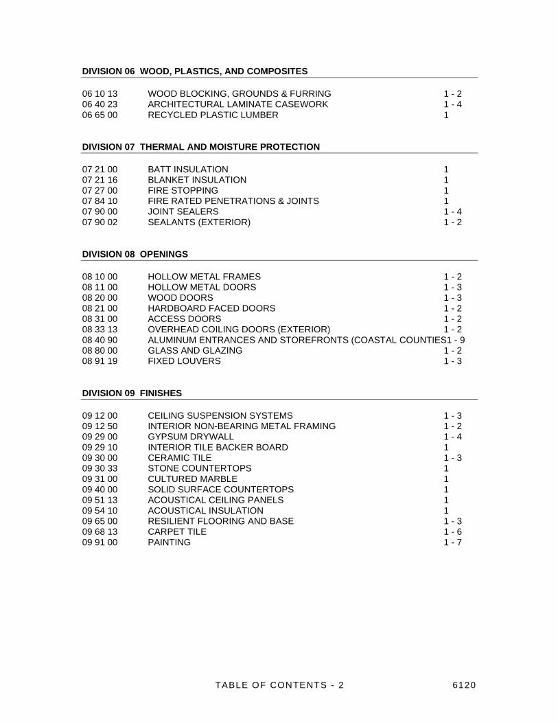
TABLE OF CONTENTS - 2 6120
DIVISION 06 WOOD, PLASTICS, AND COMPOSITES
06 10 13 WOOD BLOCKING, GROUNDS & FURRING 1 - 2
06 40 23 ARCHITECTURAL LAMINATE CASEWORK 1 - 4
06 65 00 RECYCLED PLASTIC LUMBER 1
DIVISION 07 THERMAL AND MOISTURE PROTECTION
07 21 00 BATT INSULATION 1
07 21 16 BLANKET INSULATION 1
07 27 00 FIRE STOPPING 1
07 84 10 FIRE RATED PENETRATIONS & JOINTS 1
07 90 00 JOINT SEALERS 1 - 4
07 90 02 SEALANTS (EXTERIOR) 1 - 2
DIVISION 08 OPENINGS
08 10 00 HOLLOW METAL FRAMES 1 - 2
08 11 00 HOLLOW METAL DOORS 1 - 3
08 20 00 WOOD DOORS 1 - 3
08 21 00 HARDBOARD FACED DOORS 1 - 2
08 31 00 ACCESS DOORS 1 - 2
08 33 13 OVERHEAD COILING DOORS (EXTERIOR) 1 - 2
08 40 90 ALUMINUM ENTRANCES AND STOREFRONTS (COASTAL COUNTIES1 - 9
08 80 00 GLASS AND GLAZING 1 - 2
08 91 19 FIXED LOUVERS 1 - 3
DIVISION 09 FINISHES
09 12 00 CEILING SUSPENSION SYSTEMS 1 - 3
09 12 50 INTERIOR NON-BEARING METAL FRAMING 1 - 2
09 29 00 GYPSUM DRYWALL 1 - 4
09 29 10 INTERIOR TILE BACKER BOARD 1
09 30 00 CERAMIC TILE 1 - 3
09 30 33 STONE COUNTERTOPS 1
09 31 00 CULTURED MARBLE 1
09 40 00 SOLID SURFACE COUNTERTOPS 1
09 51 13 ACOUSTICAL CEILING PANELS 1
09 54 10 ACOUSTICAL INSULATION 1
09 65 00 RESILIENT FLOORING AND BASE 1 - 3
09 68 13 CARPET TILE 1 - 6
09 91 00 PAINTING 1 - 7

TABLE OF CONTENTS - 3 6120
DIVISION 10 SPECIALTIES
10 14 00 IDENTIFYING DEVICES 1 - 2
10 21 13 SOLID PLASTIC COMPARTMENTS/PARTITIONS 1 - 2
10 26 13 HIGH IMPACT CORNER GUARDS 1
10 28 00 TOILET AND BATH ACCESSORIES 1 - 2
10 44 00 FIRE EXTINGUISHERS & CABINETS 1 - 2
10 51 13 METAL LOCKERS 1 - 3
10 67 00 SHELVING 1
10 73 13 ALUMINUM CANOPIES (CUSTOM) 1 - 2
DIVISION 11 EQUIPMENT
11 31 00 RESIDENTIAL KITCHEN EQUIPMENT 1 - 2
11 40 30 FOOD SERVICE EQUIPMENT 1 - 4
11 52 13 MANUAL PROJECTION SCREENS 1 - 2
DIVISION 12 FURNISHINGS
12 21 10 WINDOW TREATMENT 1 - 3
12 48 00 RUGS AND MATS 1 - 2
12 93 13 BICYCLE RACKS 1
DIVISION 13 SPECIAL CONSTRUCTION
13 34 19 METAL BUILDING SYSTEM 1 - 3
DIVISION 14 CONVEYING EQUIPMENT
14 42 16 VERTICAL WHEELCHAIR LIFT 1 - 4
DIVISION 21 FIRE SUPPRESSION
Not used.
DIVISION 22 PLUMBING See Plumbing Specifications
DIVISION 23 HEATING, VENTILATING & AIR CONDITIONING See Mechanical Spec.
DIVISION 26 ELECTRICAL See Electrical Specifications
DIVISION 27 COMMUNICATIONS See Communications Spec on Drawings

TABLE OF CONTENTS - 4 6120
DIVISION 28 ELECTRONIC SAFETY AND SECURITY
Not used.
DIVISION 31 EARTHWORK
31 31 16 TERMITE CONTROL 1 - 2
DIVISION 32 EXTERIOR IMPROVEMENTS
32 31 13 CHAIN LINK FENCING AND GATES 1 - 4
DIVISION 33 UTILITIES
Not used.

AVAILABLE INFORMATION – 00 30 00-1 1140
SECTION 00 30 00 – AVAILABLE INFORMATION
PART 1 GENERAL
This section includes references to:
Survey Information
Existing Hazardous Material Information
Geotechnical Data
PART 2 – DATA
SURVEY INFORMATION:
A site survey is included with the prepared architectural and engineering construction documents. The
project architects and engineers do not validate the accuracy of the survey document and direct the
bidders and contractors to verify dimensions in the field.
The State of Florida Registered Land Surveyor for this Work is: Robert A. Stevens & Associates, Inc.,
210 Lena Vista Blvd., Auburndale, FL 33823, 863.559.1216, [email protected] .
EXISTING HAZARDOUS MATERIAL INFORMATION:
Available for bidders and contractors for this Work is a copy of a hazardous materials report covering the
investigation of and sampling for the existence of asbestos and lead-based paint in the existing portions
of the project area.
The investigation, sampling and report was undertaken by: Robert B. Sport, CIAQP, Universal
Engineering Sciences, Inc., 3532 Maggie Boulevard, Orlando, FL 32811, 407.423.0504, ext. 23306,
407.694.4968 (cell), [email protected] .
If abatement is to be a part of the work of this contract, specifications for abatement will be included and
the scope of work will identify such.
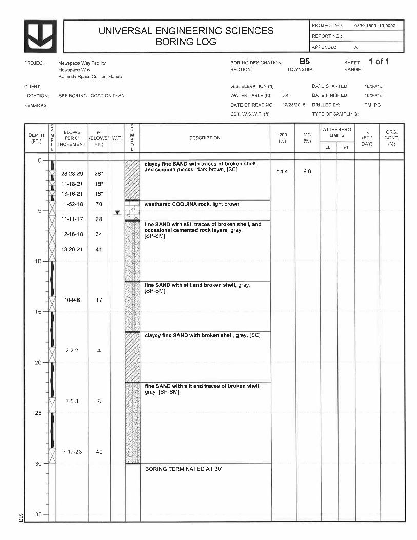
GEOTECHNICAL DATA:
If applicable, a subsurface soils and geotechnical report with soils stabilization and foundation
recommends will be included with the construction documents for the benefit of bidders and contractors
working on the project.
The geotechnical work has been undertaken and prepared by : (not applicable this project).
If there are questions regarding results and recommendations, inquiries shall be made directly to the
geotechnical engineer. The geotechnical report for this work, if applicable, is included with this
Specifications Book.
END OF SECTION 00 30 00


PROJECT FORMS – 00 60 00-1 6120
SECTION 00 60 00- PROJECT FORMS
INSTRUCTIONS:
The forms and certificates listed below are to be used by the Contractor for submissions for
contractual and administrative requirements specified herein.
Requirements and instructions on the forms may constitute extensions of, or additions to, the
contractual conditions of the contract and the general requirements of the specifications.
Prepare all forms as required with all blank spaces filled in, in ink or typewritten.
PROJECT FORM LISTING:
TITLE DOCUMENT NUMBER
Certificate of Insurance AIA Doc. G-705
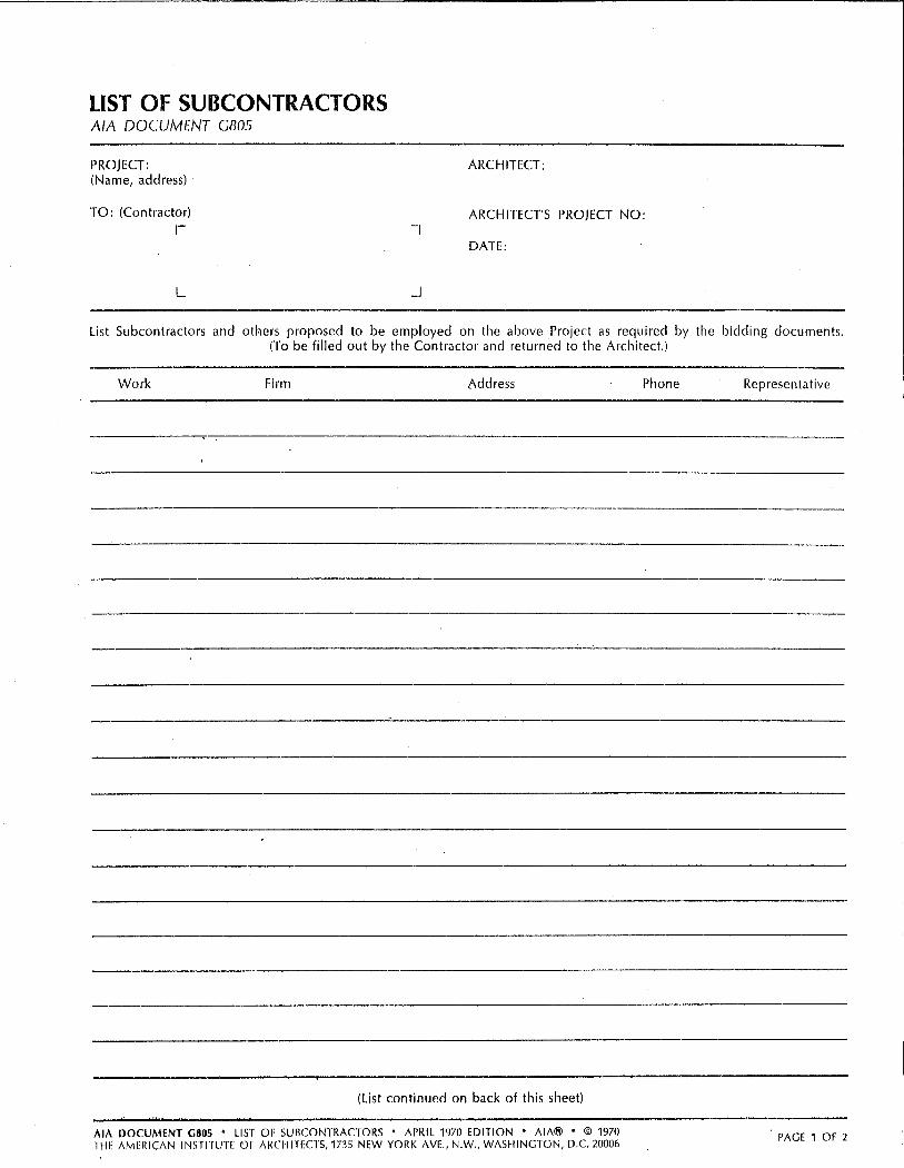
List of Subcontractors AIA Doc. G-805
Application & Certificate for Payment AIA Doc. G-702
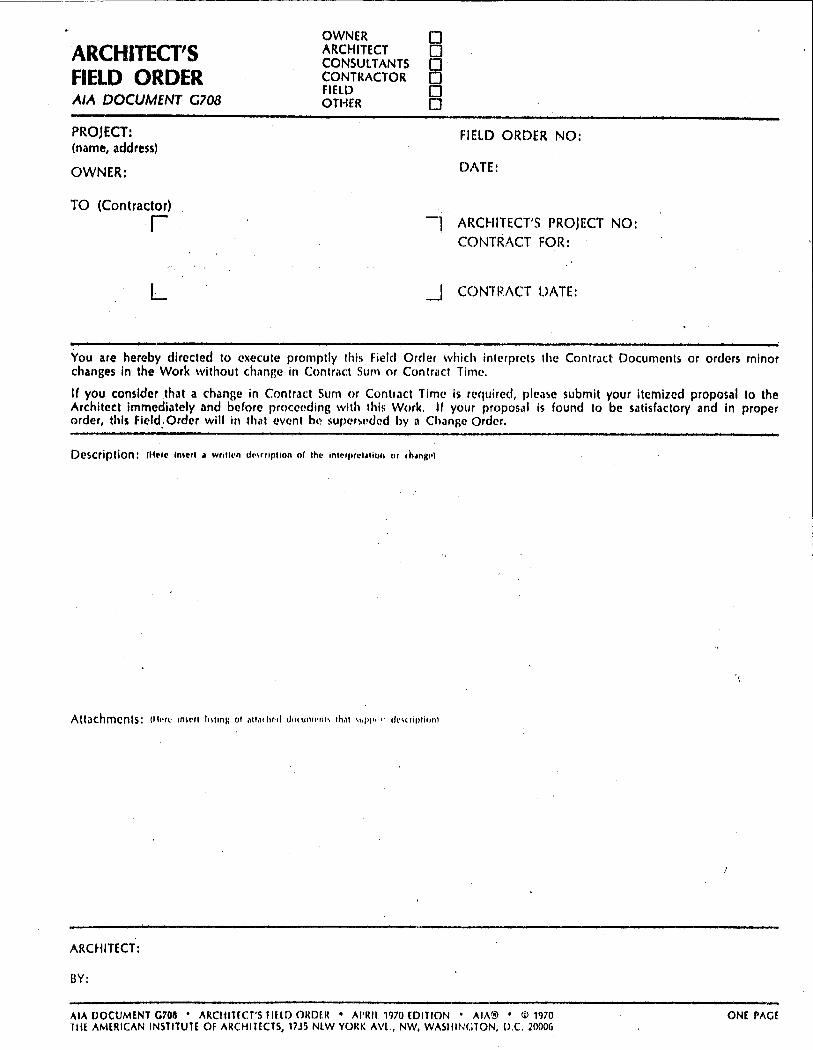
Architect's Field Order AIA Doc. G-708
Proposal Request AIA Doc. G-709
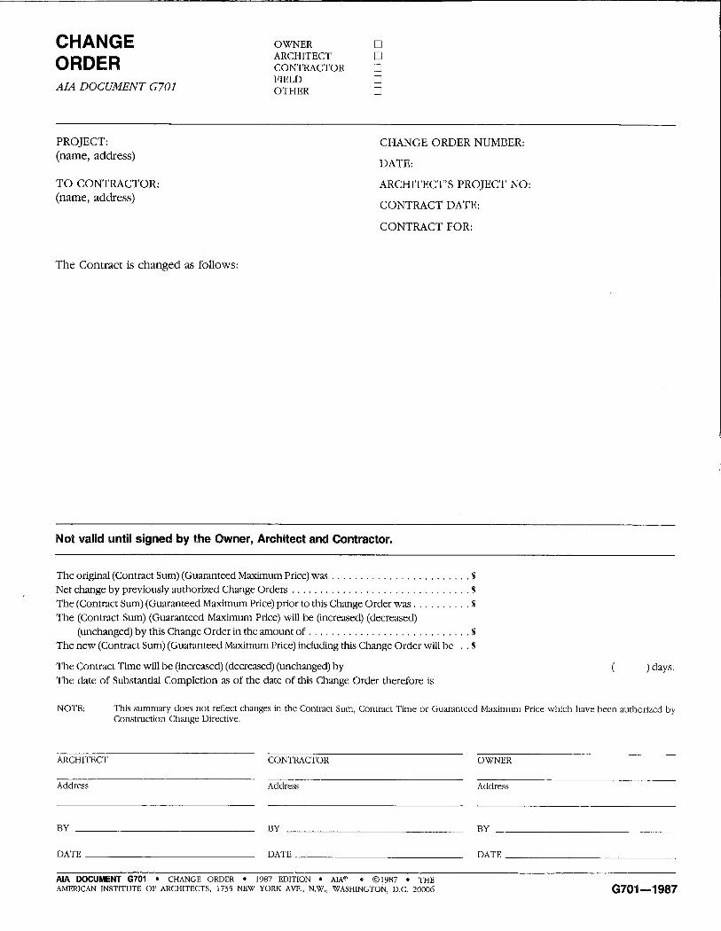
Change Order AIA Doc. G-701
Certificate of Substantial Completion AIA Doc. G-704
Consent of Surety Company to
Final Payment AIA DOC. G-707
Contractor's Affidavit for Payment of
Debts and Claims AIA Doc. G-706
Contractor's Affidavit of Release of
Liens (Final Release) AIA Doc. G-706A
END OF SECTION 00 60 00


GENERAL CONDITIONS – 00 72 00-1 6110
SECTION 00 72 00 - GENERAL CONDITIONS
REFERENCE:
The general conditions of this contract are the American Institute of Architects Document A201,
"General Conditions of the Contract for Construction", 2007, Fourteenth Edition, hereinafter
referred to as the "General Conditions".
A copy of the General Conditions may be obtained from the Architects office at cost. Additional
copies may be purchased from the American Institute of Architects, 1735 New York Avenue,
N.W., Washington, D.C. 20006.
The General Conditions shall apply to each and every section of the Work as though written in full
therein.
DEFINITIONS:
The following definitions shall amend the General Conditions in a manner to specifically apply to
this project.
Contract Documents: The Contract Documents, as referred to herein, consist of the Contract, the
Legal Advertisements covering Opening of Bids, the Performance Bond, the Labor, and Material
Payment Bond, the Instruction to Bidders and General Conditions, the Special Conditions,
Technical Specifications, Contract Drawings, and Addenda, all incorporated into the contract
before its execution. These documents apply to each and every division and section of the
specifications, the plans and working drawings and all modifications issued after the execution of
the contract, as if written in full therein. All plans and drawings, general requirements, and
technical specifications, modifications, and all other items included as a part of the Summary of
Work Section 01 10 00 are also a full and effective portion of the Contract Documents.
Owner: As herein used shall mean: BLUE ORIGIN
Architect: As herein referred to shall mean Architects RZK, Inc., 600 Florida Avenue, Suite 201,
Cocoa, Florida 32922.
Contractor: As used herein refers to the person, firm, or corporation authorized to do business in
the State of Florida with whom a contract has been made directly or through accredited
representatives that have entered into a contract with the Owner for the performance of the work
described by these documents.
Other Contractors: As used herein shall mean any person, firm or corporation with whom a
contract has been made by the Owner for the performance of any work on the site of this building,
which work is not a portion of the work covered by this contract.
Inspector: As used herein shall mean any authorized representative of the Owner.
Subcontractor: As used herein refers to and shall include all those performing labor or furnishing
materials under the supervision and control of the Contractor and not in privity of contract with the
Owner.
Superintendent: As used herein refers to the executive representative of the Contractor who is
present on the work at all times during progress, authorized to receive and fulfill instructions from
the Architect, and capable of superintending work efficiently.
Surety: As used herein shall mean the firm, corporation, or individual which is bound by the
Performance Bond, Labor and Material Payment Bond, with and for the Contractor, and which

GENERAL CONDITIONS – 00 72 00-2 6110
engages to be responsible for the Contractor's acceptable Performance, Labor and Material
Payment of the work and for payment of all debts pertaining thereto.
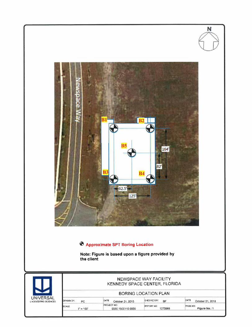
Project: As used herein shall mean the construction of Blue Origin Manufacturing Annex, 8201
Newspace Drive, Merritt Island, Florida
Proposal Guarantee: As used herein shall mean the Bid Bond or good faith deposit, acceptable
to the Owner, designated in the proposal to be furnished by the bidder as a guarantee of good
faith to enter into a contract with the Board, if the contract is awarded to him.
Written Notice: Shall be deemed to have been duly served if delivered in person to the individual
or to a member of the firm or to an officer of the corporation for whom it is intended, or if delivered
at or sent by certified or registered mail to the last business address known to him who gives
notice.
Work: As used herein means labor or materials furnished by the Contractor or Subcontractor.
Completion: As used herein means that the facility called for is fully executed and completed in
accordance with the contract.
Plans: As used herein include all drawings and specifications.
Punch List: Is a compilation of items which have been found to require further attention by
Contractor.
END OF SECTION 00 72 00

SUPPLEMENTARY GENERAL CONDITIONS – 00 73 00-2 6110
2.2.5.1 Upon award of the Contract, the Contractor will be furnished signed and sealed
permit sets of the Contract Drawings and Specifications.
ARTICLE 3 - CONTRACTOR:
3.3.4 Contractor is responsible for correlating the work of Subcontractors and exercising
general superintendence over them. Contractor shall determine the extent of work
of Subcontractors so the necessary placing of sleeves, inserts, anchors, hangers,
bolts, bucks, sub-bases, pipes, conduits, mounting devise and other roughing-in
may be accomplished by the proper time to provide for the ultimate placing or
installing of equipment and fixtures. Contractor shall see that the work of
Subcontractors is performed properly so there will be a minimum of cutting of work
in place.
3.4.3.1 Contractor and his Subcontractors shall have full control of all persons in their
employ; however, the Owner/Architect shall have the right to require Contractor to
remove any Contractor or Subcontractor employee(s) whose actions have a
disruptive effect upon the construction site. Further, Owner shall have the right to
require Contractor to replace, within ten (10) days of Contractor's receipt of
Owner's written notice, any employee or supervisor of Contractor or its
Subcontractors.
3.4.4 Contractor shall notify Owner of potential jurisdictional disputes of or claims of two
or more trades for work and shall consult with the Owner relative to any potential or
actual slowdowns, stoppage, picketing or any other action that might result in labor
disputes or work disruption at the Project Site.
3.4.5 To expedite inspection and testing of materials, the Contractor shall furnish
complete statements to the Architect as to the origin, composition and manufacture
of all materials to be used in the Work. Such statements shall be furnished
promptly after execution of the Contract but, in all cases, prior to delivery of such
materials. At the Owner's option, materials may be approved at the source of
supply before delivery to the site. If it is found after trial that sources of supply for
previously approved materials do not produce specified products, the Contractor
shall furnish materials from other sources approved by Owner.
3.5.1 Contractor agrees to preserve for Owner any and all warranties furnished by
Subcontractors and materialmen. In the event Contractor is unable to obtain from
any Subcontractor or materialmen the warranty required by the Contract
Documents, Contractor expressly assumes the risk of providing such warranty in
lieu of the warranty sought from such Subcontractor or materialmen. Contractor
shall accept no limitation of remedies or exclusion of warranties clauses in its
Subcontracts or purchase orders or, alternatively, if such clauses are included in its
Subcontracts or purchase orders, Contractor agrees to be fully liable to Owner for
all damages sustained by the Owner or those claiming through the Owner
notwithstanding such limitation or exclusion clauses. The Owner shall not be
bound by any limiting language or clauses contained in any Subcontract or
purchase order entered into by Contractor and no limiting language or clauses shall
reduce, affect or limit in any way Contractor's liability to Owner. Any exception to
this provision must be agreed to in writing by Owner.
3.7.4 (related to concealed or unknown conditions): line 6, delete 21 days and insert 7
days.
3.7.6 Where requirements of the Contract Documents differ from laws, ordinances, rules,
regulations, orders, the Building Code or the requirements of authorities having

SUPPLEMENTARY GENERAL CONDITIONS – 00 73 00-3 6110
jurisdiction, the more stringent requirements shall govern. Subject to the provisions
of Subparagraph 3.7.2, any major changes in the scope of the Work as the result
of laws, ordinances, rules, regulations, orders or the Building Code, the
requirements of which are more stringent than the Contract Documents, shall be
accompanied by appropriate Change Order Request from the Contractor.
3.7.7 On behalf of the Owner, the Contractor shall file a Notice-Of-Commencement, in
accordance with State of Florida laws, with the applicable jurisdiction for the
project.
3.9.2 Delete existing paragraph 3.9.2 and insert: “Contractor's superintendent(s) and/or
project manager(s) shall have had recent experience in the type of Work to be
performed under this Contract which shall be specified in a written Notice to
Owner. Owner shall be deemed to accept such person(s) unless, within fourteen
(14) days after receipt of such notice, Owner objects in writing to the selection. If
Owner so objects, Contractor shall select another person and the above process
shall be repeated. No adjustment in Contract time or Contract Sum shall be
permitted for compliance with this subparagraph. Should Contractor's
superintendent or project manager have to be replaced during the course of this
Contract, this subparagraph shall apply.”
3.11.1 The Job Superintendent, and the plumbing, heating, ventilation and electrical
subcontractors shall make and keep current red line corrections on drawings,
showing exact location of underground lines. The red line drawings shall include
all underground or concealed pipes, conduit, ducts, and all existing items which
were not installed exactly as shown on drawings. Failure to keep record drawings
current will delay processing of monthly payments.
3.12.11 Architect's approval of Shop Drawings or Samples of Product Data which deviate
from the Contract Documents does not authorize change to the Contract. Any
changes to the Contract affected by such Shop Drawings, Samples or Product
Data, shall be recorded by the Contractor on the as-builts record drawings.
Construction cost associated with changes indicated in approved shop drawing
shall be borne by the Contractor who proposes the change.
3.13.1 Contractor's proposed use of the Site shall be subject to Owner's prior written
approval.
3.15.3 At reasonably frequent intervals during progress of Work, Contractor shall clean up
site, building and access, and dispose of waste materials, rubbish and debris.
Contractor shall provide containers and location on site for collection of waste
materials, rubbish and debris. Contractor shall not allow waste materials, rubbish
and debris to accumulate and become an unsightly or hazardous condition.
Contractor shall lower waste materials in a controlled manner with as few handlings
as possible and shall not drop or throw materials from heights. Contractor shall
schedule cleaning operations so that dust and other contaminants resulting from
cleaning process will not fall on wet, newly painted surfaces.
Contractor shall schedule clean-up operations such that it does not interfere with
the Owner's operations should that apply.
Contractor shall conduct clean-up and disposal operations to comply with local
ordinances and anti-pollution laws. Burning or burying of rubbish and waste
materials on the site is not permitted. Disposal of volatile fluid wastes (such as
mineral spirits, oil, or paint thinner) in storm or sanitary sewer systems or into

SUPPLEMENTARY GENERAL CONDITIONS – 00 73 00-1 6110
SECTION 00 73 00 - SUPPLEMENTARY GENERAL CONDITIONS
SCOPE:
The Supplementary General Conditions modify, change, delete from or add to the General
Conditions (A.I.A. 2007 Edition) and shall apply to each and every Section of the Work as though
written in full therein.
SUPPLEMENTARY CONDITIONS:
The following paragraphs and subparagraphs take precedence over the General Conditions.
Where any part of the General Conditions is modified or deleted by the Supplementary General
Conditions, the unaltered provisions remain in effect.
Paragraph numbers and titles refer to like numbers and titles in the General Conditions.
ARTICLE 1 - GENERAL PROVISIONS:
1.1.3.1 The work of this Contract shall be the construction of the BLUE ORIGIN –
MANUFACTURING ANNEX, MERRITT ISLAND, FL
1.1.6.1 The section, article and paragraph headings in the Specifications are inserted only
as a matter of convenience and for reference, and in no way define, limit or
describe the scope or intent of any provision of the Contract Documents.
1.2.2.1 Scope paragraphs placed at the beginning of the Sections present a brief indication
of the principal Work included in that Section, but do not limit Work to subject
mentioned.
1.2.2.2 The Specifications have been partially "streamlined" and some works and phrases
have been intentionally omitted. Missing portions shall be provided by inference as
with notes on drawings.
1.2.4 Locations of piping, ductwork, conduit, outlets and the like, shown on the
mechanical and electrical drawings are diagrammatic, except where specifically
indicated by dimension or as existing. Therefore, it shall be the duty of the
Contractor and his subcontractors to consult with each other and verify conditions,
and in each case where there is a question of doubt as to adequacy of space or
indicated arrangements, to submit a workable solution to the Architect for his
approval before installing the work which is questionable.
1.2.4.1 Failure to report a conflict or ambiguity in the Contract Documents shall be deemed
evidence that the Contractor has elected to proceed in the more expensive
manner.
1.2.5 Upon award of the Contract, the Contractor will be furnished a disk containing the
Contract Drawings and Specifications.
ARTICLE 2 - OWNER
2.2.3.1 The Owner does not warrant the accuracy of said surveys or utility locations and
the Contractor shall be responsible for verifying all existing conditions. Those
conditions which vary substantially from that noted or reasonably inferred therefrom
will be considered for a change in the contract work.

SUPPLEMENTARY GENERAL CONDITIONS – 00 73 00-4 6110
streams or waterways or onto the ground is not permitted. Contractor shall remove
waste materials, rubbish and debris from the Site and legally dispose of at public or
private dumping areas off Owner's property.
Contractor shall vacuum clean interior building areas when ready to receive finish
painting and continue vacuum cleaning on an as needed basis until the building
areas are ready for Beneficial Occupancy.
3.18.1 (related to indemnification), first sentence, will be amended, in part, to read, “To the
fullest extent permitted by law the Contractor shall indemnify and hold harmless the
Owner, Architect, Architect’s consultants, and agents, employees of any of them
from and against claims, damages, losses and expenses, including, but not limited
to attorneys’ fees, arising out of or resulting from performance of the Work,
including any violation of Devereux’s Safety Protocols…” Devereux’s Safety
Protocols will be a part of the Contract
ARTICLE 4 - ARCHITECT
4.2.4.1 The Owner and Contractor shall issue all communications between each other
simultaneously to the Architect.
ARTICLE 5 - SUBCONTRACTORS
5.3 (related to subcontractual relations) will be amended to include an additional
sentence, which will read, “Each subcontract agreement shall provide for the
subordination of any mechanics’ liens to the lien of a mortgage or security interest
lien that may exist.”
ARTICLE 7 - CHANGES IN THE WORK
7.1.4 If Contractor wishes to make a claim for an increase in the Contract Sum, he shall
give Owner written notice thereof within ten days after the occurrence of the event
given rise to such claim. The amount of the adjustment shall be determined by one
of the methods set forth in subparagraph 7.3.3. Any change in the Contract Sum
resulting from such claim shall be authorized by written Change Order and shall not
be valid or effective unless the written Change Order has been signed by
Contractor, Owner and Architect.
7.2.2 For change order work, the maximum allowance of 5% profit and 10% overhead
shall apply to the Contractor for work performed by his forces and to
subcontractors and sub-subcontractors (combined if by both) for actual receipted
material and direct labor costs. The Contractor may mark up subcontractor and
sub-subcontractor cost by 5% maximum.
7.3.3.5 For each method previously listed (7.3.3.1 through 7.3.3.4) The Contractor shall
submit a detailed cost breakdown for each task listed in a Proposal Request, AIA
Doc. G709, or Change Order request. A cost breakdown shall mean the elements
listed in 7.3.7.1 through 7.3.7.5. All cost elements shall be related directly to the
tasks listed in the Proposal Request or Change Order Request. Other than profit,
overhead and bond premiums, no cost shall be determined in a percentage basis.
The Contractor shall submit a reply to the Architect's Proposal Request within ten
(10) days of its date unless a letter is received by the Architect prior to the tenth
day stating the cause for a delayed response. Upon receipt of a Contractor
response, the Owner and Architect shall review the amounts. The Architect shall
prepare a change order directive, AIA Doc. G701 as negotiated or deny the change

SUPPLEMENTARY GENERAL CONDITIONS – 00 73 00-5 6110
order request; or, direct the work of the change order as allowed by Subparagraph
7.3.7.
7.3.3.6 Mark-ups for overhead, profit and commission shall be per subparagraph 7.2.2
7.3.5.1 In the event of failure to reach a timely agreement on a proposal submitted by the
Contractor, the Architect and Owner may direct the Contractor to proceed whereby
the cost shall be determined in accordance with 7.3.7 but in no case shall that cost
exceed the increase of the proposal.
7.4.1 Minor changes so documented may, at a later date, be incorporated into the
Drawings or Specifications, but this will in no way be cause for Contractor to make
claim for additional cost or time if such claim has not been made promptly at the
time of receipt of such instructions.
ARTICLE 8 - TIME
8.3.4 In case of claims for extension of time because of adverse weather, such extension
of time shall be granted only when adverse weather prevented the execution of
major items or Work on normal working days. The Contractor must notify the
owner and architect immediately [within one (1) hour] when a weather delay takes
place. The Contractor shall provide an estimate of the probable effect of such
delay on the progress of the Work. "Adverse weather" shall be defined to indicate
weather which is not normal (on a 5 year average) for the Site.
8.3.5 For each calendar day that any part of the Work remains uncompleted after the
expiration of the Contract Time; including all extensions and adjustments as
agreed, sums set out in the Agreement Between Owner and Contractor as
liquidated damages, shall be deducted from any monies due Contractor or, if no
money is due Contractor, Owner shall have the right to recover said sum or sums
from Contractor, from the surety, or from both. The amount of these deductions
are to cover liquidated damages to Owner incurred by additional and other
expenses due to the failure of Contractor to complete the Work or any part of the
work within the time specified, and such deductions are not to be considered as
penalties. The sums represent liquidated damages for the loss to Owner on
account of the expense due to the employment of the Architect and to any other
expenses after the expiration of completion time.
8.3.6 By permitting the Contractor to continue and finish the Work, or any part of it, after
the date fixed for its completion or after the date to which the time for completion
may have been executed, will in no way serve as a waiver on the part of the Owner
of any of its rights under the Contract.
8.3.7 There shall be no changes in the time limits allotted for Substantial Completion of
the Work except by Change Order. Provisions similar to this are included in all
contract documents governing work to be performed under this Contract. In the
event that Contractor fails to complete any of the various work elements in the
allotted time, he shall be liable for additional costs, including all attorney's fees,
which are incurred by Owner because of failure of Contractor to complete such
work within such time limits.
8.3.8 The Contractor shall cooperate with the Owner in order to maintain the contractual
schedule. If Owner determines Contractor is falling behind schedule, contractor
must, upon written request of Owner, submit to the Architect and Owner
operational plans detailing Contractor's plan of action to regain lost time. If Owner
determines it is in its own interest, Contractor shall comply with Owner's written
SUPPLEMENTARY GENERAL CONDITIONS – 00 73 00-6 6110
orders to Contractor to take such steps as are necessary to improve progress of
the Work. These steps may include, but are not limited to, expediting delivery
times, or increasing overtime operations. No additional compensation will be made
to Contractor for work done under this subparagraph.
ARTICLE 9 - PAYMENTS AND COMPLETION
9.2.1 The Schedule of Values shall breakdown the bid price in an organized manner to
conform to the Technical Specification Index. Include cost of all required building
permits, fees, premiums, bonds, etc.
9.2.2 When the Owner seeks exemption from the Florida State Sales Tax, the Schedule
of Values shall have a column added separating the materials and building
equipment costs from other costs for each line item.
9.3.1.3 The Architect may require a rough draft of the proposed application to review with
the Contractor prior to submitting the final submittal.
9.7.1 Anything to the contrary notwithstanding, Contractor may not stop the Work for
Owner's failure to pay if Owner's nonpayment is caused by defects in the
Certificate for Payment.
9.8.1.1 Substantial completion cannot be achieved by the Contractor without express
written approval of the public authorities having jurisdiction over the work.
ARTICLE 10 - PROTECTION OF PERSONS AND PROPERTY
10.2.1.4 The Contractor shall be responsible for repair of Contractor damages to any utility
lines that are visible, shown on Contract Documents or made known in advance to
the Contractor. The Contractor shall promptly report to the Architect any damages
to lines not made known to him in advance. Locations of underground lines shown
in the drawing are based on best available information, but are not necessarily
exact in regard to location or number of lines.
10.2.8.1 Contractor agrees to abide by OSHA and any other safety regulations or regulatory
agencies. Contractor will promptly report to Architect all lost time, injuries or
property damage involving its work or employees. Such report shall be in writing
and in a form acceptable to Architect.
10.2.9 When required by law or for the safety of the Work, Contractor shall shore up,
brace, underpin and protect foundations and other portions of existing structures
which are in any way affected by the Work. Contractor, before commencement of
any part of the Work, shall give any notices required to be given to adjoining
landowners or other parties.
ARTICLE 11 - INSURANCE AND BONDS
11.1.3 (related to certificates of insurance), second sentence will be amended to read,
“These certificates and the insurance provisions required by this Section 11.1 shall
contain a provision that coverages afforded under the policies will not be changed,
canceled or allowed to expire until at least 30 days’ prior written notice has been
given to the Owner.
11.1.5 Certificates of Insurance for all required insurance coverages shall be forwarded to
the Owner prior to the beginning of construction. All insurance shall remain in

SUPPLEMENTARY GENERAL CONDITIONS – 00 73 00-7 6110
effect until the Owner accepts the project as substantially complete. The
Contractor shall include the cost of this insurance as part of his original bid.
11.1.5.1 Insurance Requirements.
A. Contractor’s insurers shall maintain an AM Best Rating of at least A-: IX and must be licensed
in the state where work is being done. Contractor’s insurance coverage must be written on a per
Occurrence form.
B. Contractor’s Commercial General Liability, Automobile Liability, Pollution Liability (when
applicable) and Umbrella Liability policies shall be endorsed to name Devereux, its Officers,
Trustees, employees, and independent contractors as Additional Insureds.
C. Contractor’s insurance policies must
(1) include a waiver of subrogation in favor of Blue Origin,
(2) with respect to required liability policies, provide cross liability coverage as would be
achieved under the standard ISO separation of insured clause;
(3) stipulate that with the exception of property insurance, the Contractor’s policies of
insurance shall be considered as primary insurance and any similar policy maintained by
Devereux shall be considered as excess and non-contributory;
(4) designate Devereux as an additional insured (excepting Contractor’s Workers’
Compensation and Professional Liability (if applicable) policies) using ISO endorsement forms set
forth below.
(5) provide coverage to Devereux for any and all bodily injury and property damage
claims, costs and expenses arising out of or in any way relating to work or operations performed
under this Agreement, including but not limited to bodily injury claims by employees of Contractor,
regardless of whether Contractor’s negligence, acts or omissions caused, contributed to or are
alleged to have caused or contributed to the injury, damage or loss for which the claim is made
D. Contractor’s failure to maintain the aforementioned insurance at any time required by this
Agreement is a material breach of its obligations under this Agreement. In the event of any such
breach, Contractor shall be liable to Devereux for any and all costs, liabilities, damages, penalties
or expenses (including but not limited to attorneys fees, court and settlement expenses)
sustained by Devereux in the handling, adjustment, defense and/or settlement of any claim that
would otherwise be covered by such insurance.
E. Contractor shall provide Blue Origin with thirty (30) days’ advanced written notice of the
cancellation, non-renewal or material adverse change to the specified coverage and limits.
F. Prior to the commencement of any work, Contractor shall provide the Finance Director or
his/her designee [Insert Center Name and Address] with Certificates of Insurance and relevant
endorsements for all policies set forth above evidencing that Contractor and all sub- contractors,
sub-consultants, independent contractors and any other person/entity performing duties under
this Agreement on Contractor’s behalf, have insurance coverage within the limits specified in this
Agreement and have named Devereux as an additional insured [excepting Contractor’s Workers’
Compensation and Professional Liability (if applicable) policies] as described above.
G. Contractor shall monitor the compliance of sub-contracting parties with these insurance
requirements, including maintaining Certificates of Insurance throughout the term of the contract.
In the event Contractor fails to obtain the required certificates of insurance from the Subcontractor
and a claim is made or suffered, the Contractor shall indemnify, defend and hold harmless
Devereux from any and all claims for which the required insurance would have provided
coverage. This indemnity obligation is in addition to any other indemnity obligation provided in the Contract.

SUPPLEMENTARY GENERAL CONDITIONS – 00 73 00-8 6110
11.1.5.2 Minimum Coverage Limits.
A. Contractor’s requirements. Contractor shall obtain and maintain at all times during the course
of this Agreement the following insurance and minimum limits:
(1) Workers’ Compensation as required in compliance with the limits established by all
applicable State and Federal law in which the work is to be performed and Employer’s Liability
Insurance with minimum limits of $500,000 bodily injury for each employee, $500,000 Disease
Policy limit and $500,000 Disease limit for each employee.
(2) Commercial General Liability Insurance on an “occurrence” basis including coverage for Premises and Operations, Products and Completed Operations, Personal Injury and Advertising Injury, Broad Form Property Damage, Independent Contractors, Broad Form Blanket Contractual Liability, “All Risk” Legal Liability, Coverage for Explosion, Collapse and Underground Property Damage (XCU), and Medical Payments. The minimum Limits of Liability required shall be:
Limit Per Occurrence $1,000,000 Personal Injury/Advertising Injury $1,000,000 Policy General Aggregate $2,000,000 with a “Per Project Aggregate Endorsement” Product/Completed Operations $2,000,000 Medical Payments $10,000 each person “All Risk” Legal Liability $100,000
Contractor’s Commercial General Liability must include completed operations coverage
and must be maintained for two (2) years from the day the work has been completed or the date
of the last payment, whichever is later. Additional Insured coverage during the project, and for an
additional two-year period for products/completed operations, shall be provided under ISO
additional insured endorsement CG 20 10 or CG 20 33 AND CG 20 37 or substitute form(s)
providing equivalent coverage.
(3) Automobile Liability Insurance covering any owned, hired or non-owned vehicle or
other vehicle used in the performance of services hereunder in the amount of $1,000,000
combined single limit per occurrence and including any statutorily mandated “No-Fault” Personal
Injury Protection, medical payments or Uninsured/Underinsured Motorist coverage.
(4) Umbrella Liability Insurance shall provide following form coverage in excess of the
above mentioned automobile, employers’ and general and professional liability (if applicable)
policies. Contractor’s Umbrella policy shall be at least as broad in coverage as the primary layer
policies and will contain no exclusion not on the primary layer policies. Minimum coverage limit
required is:
___ $5.0 million per occurrence and in the aggregate for those contractors involved in
Excavation, Site Work, Demolition, Roofing or any other operation involving work at
heights in excess of 20 feet, or any work involving the hiring of a general contractor and/
or construction manager for the construction of a new building or renovation of an
existing building with a total value in excess of $250,000.
__ $1.0 million per occurrence and in the aggregate for all other operations.
(5) Payment and Performance Bonds in an amount equal to 100% of the contract value are
required for all projects of $1.0 million or more. Performance and Payment Bonds may be required on
other projects, subject to the judgment of Blue Origin’s Treasurer. A letter from a surety evidencing the
Contracting Party’s ability to secure such bonds is required for any project greater than $250,000 but less
than $1.0 million.

SUPPLEMENTARY GENERAL CONDITIONS – 00 73 00-9 6110
B. Subcontractor’s requirements. Subcontractors shall be required to obtain and maintain at all
times all insurances and minimums limits listed in Section II A(1) – (4) above.
C. Additional Insured Endorsement. All policies set forth above must be maintained for two (2)
years from the day the work has been completed. Additional Insured coverage during the project,
and for the additional two year period for products/completed operations, shall be provided under
ISO additional insured endorsement CG 20 10 or CG 20 33 AND CG 20 37 or substitute form(s)
providing equivalent coverage.
D. The insurance requirements and other provisions of this Agreement shall not limit the
Contractor’s indemnification obligations set forth in elsewhere in this Agreement.
11.1.5.3 Indemnification.
A. To the fullest extent permitted by law, Contractor shall indemnify, defend and hold
Devereux, its Officers, Directors, employees, agents, contractors, representatives, affiliates, heirs
and assigns harmless from and against liability of any kind or nature, any and all claims,
judgments, suits, settlements, costs including, but not limited to any injury, harm, loss, cost,
damage, claim, expense, liability and damages arising from or in any manner related to any work
or operations performed under this Agreement regardless of the negligence or alleged
negligence of Devereux, its Officers, Directors, employees, agents, contractors, representatives,
affiliates, heirs and assigns. Upon request of Devereux, Contractor shall, at no cost or expense
to Devereux, defend any suit asserting a claim for any loss, damage, or liability specified above,
and Contractor shall pay any costs and attorneys' fees that may be incurred by Devereux in
connection with any such claim or suit. The aforesaid duty to indemnify and defend Devereux
shall commence immediately upon notice to Contractor of any such claim or suit and shall
continue unless and until a court has determined that such loss, cost, damage, claim, expense, or
liability results solely from the gross negligence or willful misconduct of Devereux or its
employees.
B. Contractor’s obligation to indemnify, defend and hold Devereux harmless shall include
but not be limited to claims by employees of Contractor and any subcontractor for bodily injury
that occurs or is alleged to have occurred in the course and scope of employment by Contractor
or any subcontractor.
ARTICLE 11.3 PROPERTY INSURANCE:
11.3.1 (related to property insurance), first sentence will be amended to read, “Unless otherwise provided, the Owner shall purchase and maintain, in a company or companies lawfully authorized to do business in the jurisdiction in which the Project is located, property insurance written on a builder’s risk, “all-Risk” or equivalent policy form in the amount of the initial Contract Sum, plus value of subsequent Contract Modification and cost of materials supplied or installed by others, comprising total value for the entire Project at the site on a replacement cost basis without optional deductibles.”
11.3.1.3 (related to property insurance deductibles), will be amended to include a second
sentence, which will read, “Owner’s payment of the property deductible does not
constitute a waiver of its Insurance Company’s rights.”
11.3.1.4.1 Although the Owner pays the Contractor for materials stored on site, it is the
responsibility of the contractor to protect these materials from theft.
11.3.3 (related to loss of use insurance), second sentence will be amended to read, “The
Owner waives all rights of action against the Contractor for loss of use of the
Owner’s property, including consequential damages due to fire or other hazards,

SUPPLEMENTARY GENERAL CONDITIONS – 00 73 00-10 6110
however caused, unless such loss is determined to be due to the negligence of the
Contractor, subcontractor, sub-subcontractor or any other party providing services
on behalf of the Contractor.”
11.3.5 (related to property insurance), first sentence will be amended to read, “If during the Project construction period the Owner insures properties, real or personal or both, at or adjacent to the site by property insurance under policies separate from those insuring the Project, or if after final payment property insurance it to be provided on the completed Project through a policy or policies other than those insuring the project during the construction period, the Owner shall waive all rights in accordance with the terms of Section 11.3.7 for damages caused by fire or other causes of loss covered by this separate property insurance, to the extent of such insurance, unless such loss is determined to be due to the negligence of the Contractor, subcontractor, sub-subcontractor or any other party providing services on behalf of the Contractor.”
11.3.7 (related to waivers of subrogation), first sentence will be amended to read, “The
Owner and the Contractor waive all rights against (1) each other and any of their
subcontractors, sub-subcontractors, agents, employees, each of the other, and (2)
the Architect, Architect’s consultants, separate contractors described in Article 6, if
any, and any of their subcontractors, sub-subcontractors, agents and employees,
for damages caused by fire or other causes of loss to the extent covered by
property insurance obtained pursuant to this Section 11.3 or other property
insurance applicable to the Work, except such rights as they have to proceeds of
such insurance held by the Owner, as fiduciary, unless such loss is determined to
be due to the negligence of the Contractor, subcontractor, sub-subcontractor or
any other party providing services on behalf of the Contractor.”
11.3.9 (related to owner’s bond upon occurrence of insured loss), first sentence shall be
amended to read, “If required in writing by a party in interest, the Owner as
fiduciary shall, upon occurrence of an insured loss, give bond for proper
performance of the Owner’s duties, at the expense of that party in interest.”
ARTICLE 11.4 PERFORMANCE BOND AND PAYMENT BOND:
11.4.1 Delete the existing paragraph and insert the following: The Contractor shall furnish
Performance Bonds and Labor & Material Payment Bonds at least equal to the
Contract price as security for the faithful performance and payment of all
Contractor's obligation under the Contract. These bonds shall identify the Owner
as the beneficiary; and, shall remain in effect until one (1) year after the date of
final payment, except as otherwise provided by law. Contractor shall also furnish
such other bonds as are required by the Supplementary Conditions. All bonds
shall be in the forms prescribed by the bidding documents or Supplementary
Conditions and be executed by such sureties as (a) are licensed to conduct
business in the State of Florida and (b) are named in the current list of "Companies
Holding Certificates of Authority as Acceptable Sureties on Federal Bonds and as
Acceptable Reinsuring Companies" as published in Circular 570 (amended) by the
Audit Staff Bureau of Accounts, U.S. Treasury Department. All bonds signed by an
agent must be accompanied by a certified copy of authority to act.
11.4.1.1 If the surety of any bond furnished by Contractor is declared bankrupt or becomes
insolvent or its right to do business is terminated in Florida. Contractor shall, within
five (5) days thereafter, substitute another bond and surety, both of which shall be acceptable to Owner.

SUPPLEMENTARY GENERAL CONDITIONS – 00 73 00-11 6110
11.4.1.2 All surety companies are subject to approval and may be rejected by the Owner
without cause, in the same manner that bids may be rejected.
ARTICLE 13 - MISCELLANEOUS PROVISIONS
13.1.1 If any covenant, condition or provision contained in the Contract Documents is held
to be invalid by any court of competent jurisdiction, such invalidity shall not affect
the validity of any other covenant, condition or provision therein contained.
13.5.7 Inspections or tests not identified in the Contract Documents, determined by
Contractor to be of his/her benefit and ordered by Contractor, shall be paid for by
the Contractor.
13.5.8 If a proposed substitution requires investigation, testing or approval to determine its
suitability for incorporation into the Work, the testing of the proposed substitution
shall be determined by the Architect. Contractor shall bear all costs of such
investigations or tests, including the Architect's additional services made necessary
by such substitutions.
ARTICLE 14 - TERMINATION OR SUSPENSION OF THE CONTRACT
14.1.2.1 Nothing in 14.1.2 shall authorize payment to Contractor for anticipated profits.
ARTICLE 15 – CLAIMS AND DISPUTES
15.1.6 (related to claims for consequential damages) deleted this sub paragraph.
15.2.1 (related to claims referred to initial decision maker), third sentence will be
amended, in part, to read, “Except for those Claims excluded by this Section
15.2.1, an initial decision shall be required as a condition precedent to mediation
binding dispute resolution of any Claim…”
15.2.1.1 Any claim for extension of time or damages for delay or acceleration shall be made
in writing to the Architect not more than ten (10) days from the commencement of
the delay or acceleration; otherwise, it shall be waived. In the case of a continuing
delay, only one claim is necessary.
15.2.5 (related to rendering the initial decision), last sentence will be amended to read,
“The initial decision shall be final and binding on the parties but subject to
mediation and, if the parties fail to resolve their dispute through mediation, to
binding dispute resolution.”
15.2.6 (related to mediation of initial decision) deleted this sub-paragraph.
15.2.6.1 (related to demand for mediation after initial decision) deleted this sub-paragraph.
15.3 (related to mediation), including 15.3.1-15.3.3, deleted this sub-paragraph.
15.4 (related to arbitration), including 15.4.1, 15.4.1.1 and 15.4.2-15.4.3 deleted this
sub-paragraph.
END OF SECTION 00 73 00

SUMMARY OF THE WORK – 01 10 00-1 6110
SECTION 01 10 00 - SUMMARY OF THE WORK
PART 1 - GENERAL
RELATED DOCUMENTS:
Work of Contract can be summarized by reference to the Contract, General Conditions &
Supplementary Conditions, specification sections as listed in the "Index of Specification Sections"
bound herewith, drawings as listed in the Drawings and addenda and modifications to the
contract documents issued subsequent to the initial printing of this project manual, and including
but not necessarily limited to printed matter referenced by any of these.
General: The work of this contract includes the construction of a new Manufacturing Annex for
Blue Origin.
Abbreviated Written Summary: The work includes the provision and installation of all materials
and equipment shown on contract drawings and/or specified in the contract specifications unless
otherwise noted.
The work includes site development, utilities and improvements. This includes site fill, paved
drives, parking area, sidewalks, covered walkway canopies, ramps, curbs, exterior signage,
electrical service and utilities to the structure. This will be included as part of the GMP for the
overall effort.
The work includes adherence to Contractual & General Requirements as identified in the
Contract.
The work includes adherence to Requirements as defined within the Florida Building Code (FBC)
2014 (5th) edition.
The work includes adherence to all pertinent requirements of other codes as referenced in the
Florida Building Code (FBC).
The work requires adherence to that identified in the Subsurface Soils Investigation Report and
findings.
The work includes site work and site drainage.
The new structure is a single story high, bay pre-engineered metal building on concrete footings,
with a slab on grade.
The exterior finishes include a standing seam metal roof and wall panels with faced batt
insulation.
The Interior finishes includes ceilings of suspended acoustical panels, painted and textured
gypsum wallboard on furring or steel stud framing. Floors are specified to be covered with carpet
tiles, ceramic tile, vinyl planks and polished, sealed concrete. Interior doors are all solid core,
some are specialty doors as specified in the documents.
The HVAC system is defined under respective Division 23 sections herein.
The Plumbing System includes toilet fixtures, showers, work sinks, condensate and rain water
collection, as well as the various piping systems for sanitary sewer and domestic water
distribution.
The Plumbing System is further defined under respective Division 22 sections herein.

SUMMARY OF THE WORK – 01 10 00-2 6110
The Electrical System includes power for convenience and industry systems, lighting for ordinary
illumination and wiring for various assembly and communication systems.
The Electrical System is further defined under respective Division 26 and 28 sections herein.
The Communications System includes features and infrastructure to support communication
system(s) and is further defined under various sections in Division 27.
PART 2 - PRODUCTS
SCHEDULE:
A project schedule is identified by Blue Origin effort and in other locations of this specification
book.
PART 3 - EXECUTION
CONSTRUCTION SUPERVISION
The Contractor shall provide a full time Project Manager or Construction Superintendent. The
Project Manager or Superintendent shall not be a subcontractor or tradesman engaged to
perform as such on these projects. No work shall be performed by the Contractor or his
subcontractors, at the site, unless either of these individuals is on site.
END OF SECTION 01 10 00

SCHEDULES, REPORTS, PAYMENTS – 01 31 00-1 4111
SECTION 01 31 00 - SCHEDULES, REPORTS, PAYMENTS
PART 1 - GENERAL
RELATED DOCUMENTS:
Drawings and general provisions of contract, including General and Supplementary Conditions
and other Division-1 Specifications sections, apply to work of this section.
COORDINATION:
Coordinate both the listing and timing of reports and other activities required by provisions of this
section and other sections, so as to provide consistency and logical coordination between the
reports. Maintain coordination and correlation between separate reports by updating at monthly
or shorter time intervals. Make appropriate distribution of each report and updated report to all
parties involved in the work including the Architect/Engineer and Owner. In particular, provide
close coordination of the progress schedule, schedule of values, listing of subcontracts, schedule
of submittals, progress reports, and payment requests.
EXISTING CONDITIONS REPORTING:
Contractor shall immediately, after notice to proceed, per section 01 41 00 Project
Coordination, prepare a listing and report of the existing site and structure(s), prior to start
of work.
CONSTRUCTION PROGRESS SCHEDULE:
Chart Schedule: The form to be used for reporting progress schedules shall be as approved or
provided by the Architect. Secure critical time commitments for performing major elements of the
work. Within 20 days of the date established for "commencement of the work", submit a
completed progress schedule, in accordance with the form instructions.
CPM Scheduling: CPM scheduling is required per the SBBC Contractual & General Conditions.
For specific requirements refer to those documents.
Distribution: Following the initial submittal to and response by the Architect/Engineer, print and
distribute progress schedules to the Architect/Engineer and Owner (3 copies minimum).
Schedule Updating: Update schedule as required to maintain accurate current information and at
least monthly. Minimally, submit three (3) copies minimum with the monthly application for
payment.
SUBMITTAL SCHEDULE:
General: Immediately after acceptance of the fully developed progress schedule, prepare a
complete schedule of work-related submittals. Correlate this submittal schedule with the listing of
principal subcontractors, as required by the General Conditions, and with Section 01 33 00 SHOP
DRAWINGS, PRODUCT DATA AND SAMPLES.
SPECIAL REPORTS:
General: Submit special reports directly to the Owner’s representative within one day of an
occurrence. Submit a copy of the report to the Architect and other entities that are affected by the
occurrence.
Reporting Unusual Events: When an event of an unusual and significant nature occurs at the
site, prepare and submit a special report. List chain of events, persons participating, response by
SCHEDULES, REPORTS, PAYMENTS – 01 31 00-2 4111
the Contractor's personnel, an evaluation of the results or effects and similar pertinent
information. Advise the Owner in advance when such events are known or predictable.
Reporting Accidents: Prepare and submit reports of significant accidents, at site and anywhere
else work is in progress. Record and document data and actions. For this purpose, a significant
accident is defined to include events where personal injury is sustained, or property loss of
substance is sustained, or where the event posed a significant threat of loss or personal injury.
PROGRESS MEETINGS, REPORTING:
General: In addition to specific coordination and pre-installation meetings for each element of
work, and other regular project meetings held for other purposes, hold general progress meetings
twice a month with time coordinated with preparation of the payment requests. Review each
entity's present and future needs including interface requirements, time, sequences, deliveries,
access, site utilization, temporary facilities and services, hours of work, hazard and risks,
housekeeping, change orders, and documentation of information for payment requests. Discuss
whether each element of current work is ahead of schedule, on time, or behind schedule in
relation with updated progress schedule. Determine how behind-schedule work will be expedited,
and secure commitments from entities involved in doing so. Discuss whether schedule revisions
are required to ensure that current work and subsequent work will be completed within Contract
Time. Review everything of significance which could affect progress of the work.
Initial Progress Meeting: Schedule initial progress meeting, recognized as "Pre-Construction
Conference", for a date not more than 10 days after date of commencement of the work. Use it
as an organizational meeting, and review responsibilities and personnel assignments.
Reporting: Within 3 days after each progress meeting date, distribute copies of minutes-of-the-
meeting to each entity present and to others who should have been present. Include brief
summary (in narrative form) of progress of the work since previous meeting and report.
Schedule Updating: Immediately following each progress meeting, where revisions to progress
schedule have been made or recognized, revise progress schedule. Reissue revised schedule
concurrently with report of each meeting.
Daily Reports: Prepare a daily report, recording the following information concerning events at
the site; and submit duplicate copies to Architect/Engineer at regular intervals not exceeding
weekly intervals:
List of subcontractors at the site
List of separate contractors at the site
Approximate count of personnel at the site
High/low temperatures, general weather conditions
Accidents (refer to accident reports)
Meetings and significant decisions
Unusual events (refer to special reports)
Stoppages, delays, shortages, losses
Meter readings and similar recordings
Emergency procedures, field orders
Orders/requests by governing authorities
Change orders received, implemented
Services connected, disconnected
Equipment system tests and start-ups
Partial completions, occupancies
Substantial completions approved
SCHEDULE OF VALUES:

SCHEDULES, REPORTS, PAYMENTS – 01 31 00-3 4111
General: Prepare the schedule of values, as required by the General Conditions, in conjunction
with the preparation of the progress schedule. Coordinate preparation of schedule of values and
progress schedule. Correlate line items with other administrative schedules and the forms
required for the work, including the progress schedule, payment request form, listing of
subcontractors, schedule of allowances, schedule of alternatives, listing of products and principal
suppliers and fabricators, and the schedule of submittals. Provide breakdown of the Contract
Sum, by specification section, in sufficient detail to facilitate continued evaluation of payment
requests and progress reports. Break down principal subcontract amounts into several line items.
Round off to the nearest whole dollar, but with the total equal the Contract Sum. Submit for
review and approval by A/E prior to first application submittal.
PAYMENT REQUESTS:
General: Except as otherwise indicated, the progress payment cycle is to be regular. Each
application must be consistent with previous applications and payments. Certain applications for
payment, such as the initial application, the application at substantial completion, and the final
payment application involve additional requirements.
Waivers of Lien: Submit waivers of lien, per the General Conditions, from every entity (including
Contractor) who could lawfully and possibly file a lien in excess of $200 arising out of the
Contract, at intervals identified within those documents. Submit partial waivers for the amount
requested, prior to deduction or retainage, on each item. When the application shows completion
of an item, submit final or full waivers. The Owner reserves the right to designate which entities
involved in the work must submit waivers.
Payment Application Times: The "date" for each progress payment application is as indicated in
Owner-Contractor Agreement or, if none is indicated therein, it is the 25th day of each month.
The period of construction work covered by each payment request is period indicated in Owner-
Contractor Agreement or, if none is indicated therein, it is the 25th day of previous month or day
following end of previous period to 24th day of present month.
Application Preparation: Except as otherwise indicated, complete every entry provided for on the
form, including notarization and execution by authorized persons. Incomplete applications will be
returned by Architect/Engineer without action. Entries must match current data of schedule of
values and progress schedule and report. Listing must include amounts of change orders issued
prior to last day of the "period of construction" covered by application.
Payment will be for work installed in place in a correct and operable manner. Payment for
material stored at the project site will not be considered in the application for payment process.
Initial Payment Application: The principal administrative actions and submittals which must
precede or coincide with submittal of contractor's first payment application can be summarized as
follows, but not necessarily by way of limitation submit at least three (3) copies of each unless
noted elsewhere to be more:
Listing of subcontractors and principal suppliers and fabricators
Schedule of values
Progress schedule
Schedule of submittals
Listing of Contractor's staff assignments and principal consultants
Copies of acquired building permits and similar authorizations and licenses from governing
authorities for current performance of the work

SCHEDULES, REPORTS, PAYMENTS – 01 31 00-4 4111
Performance and/or payment bonds
Evidence satisfactory to Owner that Contractor's insurance coverage have been secured
Data needed to acquire Owner's insurance coverage
Typical Monthly Payment Application:
Provide a “rough” application for initial review; thereafter, provide at least three (3) copies of the
following items by transmittal listing each:
• Application For Payment, properly numbered
• Updated Schedule of Values
• Updated Progress Schedule
• Waivers of Lien from the previous pay request
• Stored Material invoices, as needed.
Application at Time of Substantial Completion: Following issuance of Architect's or Engineer's
"certificate of substantial completion", and as applicable, a payment application may be prepared
allowing 100% completion of the work, if it is 100% completed, minus the retainage; and,
submitted by Contractor. The principal administrative actions and submittals which must proceed
or coincide with such special applications are summarized under Section 01 77 00 - PROJECT
CLOSE-OUT.
Final Payment Application: The administrative actions and submittals which must precede or
coincide with submittal of contractor's final payment application are also summarized under
Section 01 77 00 - PROJECT CLOSE-OUT.
Application Transmittal: Submit 3 originally executed copies of each payment application.
Transmit each copy with a transmittal form listing those attachments, and recording appropriate
information related to application in a manner acceptable to Architect/Engineer. Transmit to
Architect/Engineer by means ensuring receipt within 24 hours.
PART 2 - PRODUCTS (Not Applicable)
PART 3 - EXECUTION (Not Applicable)
END OF SECTION 01 31 00

SHOP DRAWINGS, PRODUCT DATA AND SAMPLES – 01 33 00-1 6120
SECTION 01 33 00 - SHOP DRAWINGS, PRODUCT DATA AND SAMPLES
PART 1 - GENERAL
RELATED DOCUMENTS:
Drawing and general provisions of contract, including General and Supplementary Conditions and
other Division 1 Specifications Sections, apply to work of this section.
DESCRIPTION OF REQUIREMENTS:
General: This section specifies procedural requirements for non-administrative submittals
including shop drawings, product data, samples and other miscellaneous work-related submittals.
Shop drawings, product data, samples and other work-related submittals are required to amplify,
expand and coordinate the information contained in the Contract Documents.
Shop drawings are technical drawings and data that have been specially prepared for this project,
including but not limited to the following items:
- Coordination drawings
- Fabrication and installation drawings
- Schedules
- Design mix formulas
- Contractor's engineering calculations
- Specialty engineering calculations and drawings.
Standard information prepared without specific reference to a project is not considered to be shop
drawings.
Product data includes standard printed information on manufactured products that has not been
specially-prepared for this project, including but not limited to the following items:
- Manufacturer's product specifications and installation instructions
- Standard color charts
- Catalog cuts
- Printed performance curves
- Operational range diagrams
- Mill reports
- Standard product operating and maintenance manuals
Samples are physical examples of work, including but not limited to the following items:
- Partial sections of manufactured or fabricated work
- Small cuts or containers of materials
- Complete units of repetitively-used materials
- Swatches showing color, texture and pattern
- Color range sets
- Units of work to be used for independent inspection and testing
Mock-ups are special forms of samples, which are too large or otherwise inconvenient for
handling in the manner specified for transmittal of sample submittals.
Miscellaneous submittals are work-related, non-administrative submittals that do not fit in the
three previous categories; including, but not limited to the following:
- Specially prepared and standard printed warranties

SHOP DRAWINGS, PRODUCT DATA AND SAMPLES – 01 33 00-2 6120
- Maintenance agreements
- Workmanship bonds
- Project photographs
- Testing and certification reports
- Record drawings
- Field measurement data
- Operating and maintenance manuals
- Keys and other security protection devices
- Maintenance tools and spare parts
- Overrun stock
SUBMITTAL PROCEDURES:
Coordination: Coordinate the preparation and processing of submittals with the performance of
the work. Coordinate each separate submittal with other submittals and related activities such as
testing, purchasing, fabrication, delivery and similar activities that require sequential activity.
Scheduling: In each appropriate administrative submittal, such as the progress schedule, show
the principal work-related submittals and time requirements for coordination of submittal activity
with related work.
Coordination of Submittal Times: Prepare and transmit each submittal to the Architect/Engineer
within 14 days of the date of the notice to proceed. Coordinate the submittal of different units of
interrelated work so that one submittal will not be delayed by the Architect/Engineer's need to
review a related submittal. The Architect/Engineer reserves the right to withhold action on
any submittal requiring coordination with other submittals until related submittals are also
received.
Contractor's Review: Before submittal of items for review, the Contractor shall check and verify
all pertinent field dimensions, make sure that all submitted items are properly coordinated and
conform to the drawing and specifications, noting in colored pencil (any color except red) any
modifications necessary to bring them into conformity. Shop drawings shall indicate the location
of the different items shown on same, or make reference to the sheet number of the contract
specifications to which they refer, and shall further indicate compliance with the referenced
technical society or organization specifications. It shall be the Contractor's responsibility to see
that shop drawings are submitted in logical groups to permit a complete review. Individual
components which depend upon the proper selection of other components of a system are not to
be submitted separately. In the event an item is submitted independently, to expedite
procurement or for other reasons, and it is later discovered to be a poor selection due to the
influence of items which are submitted for review in a different submission, the Contractor shall
have the full responsibility for taking corrective action as directed by the Architect and at no
additional cost to the Owner. Partial or incomplete submittals will be returned without review.
The Contractor shall certify that he has verified the correctness, completeness and adequacy of
all items submitted by suitable stamp and his signature.
Shop drawings submitted without Contractor's certification, and shop drawings which are not
complete, may be returned for proper submission.
Review Time: Allow sufficient time so that the installation will not be delayed as a result of the
time required to properly process submittals, including time for resubmittal, if necessary. Advise
the Architect/Engineer on each submittal, as to whether processing time is critical to the progress
of the work and if the work would be expedited if processing time could be shortened.
Allow two weeks, ten (10) normal work days, from receipt by the Architect/Engineer's for initial
processing of each submittal. Allow a longer time period where processing must be delayed for

SHOP DRAWINGS, PRODUCT DATA AND SAMPLES – 01 33 00-3 6120
coordination with subsequent or concurrent submittals. The Architect/Engineer will advise the
Contractor when it is determined that a submittal being processed must be delayed for
coordination.
Allow one week (5 normal work days) from receipt by the Architect for reprocessing each
submittal.
No extension of time will be authorized because of the Contractor's failure to transmit submittals
to the Architect/Engineer sufficiently in advance of the work.
Submittal Preparation: Mark each submittal with a permanent label for identification.
Submittal Transmittal: Package each submittal appropriately for transmittal and handling.
Transmit each submittal from the Contractor to the Architect/Engineer, and to other destinations
as indicated, by use of a transmittal form. Submittals received from sources other than the
Contractor will not be reviewed.
An electronic pdf submittal of a suitable file size to be easily e-mailed, is preferred;
however, any signed and sealed documents must also be mailed or delivered.
Provide on the form places for the following information:
- Project name
- Date
- To:
- From:
- Names of subcontractor, manufacturer and supplier
- References
- Specification section number and type of submittal
- Submittal purpose and description
- Submittal and transmittal distribution record
- Signature of transmitter
- Contractor's certification stating that the information submitted complies with the requirements
of the Contract Documents, with a place for the Contractor's signature
Submittal Log: Prepare a submittal log indicating submittal type, extent of all anticipated
submittals and chronological disposition of each. Submit initial log showing anticipated submittals
for review and acceptance by Architect. Special attention shall be given to those submittals
requiring color selection or long lead items.
SPECIFIC SUBMITTAL REQUIREMENTS:
SHOP DRAWINGS: Information required on shop drawings includes, dimensions, identification
of specific products and materials which are included in the work compliance with specified
standards and notations of coordination requirements with other work. Provide special notation
of dimensions that have been established by field measurement. Highlight, encircle or
otherwise indicate deviations from the contract documents on the shop drawings.
Refer to all Sections for additional general requirements applicable to shop drawings.
Do not permit shop drawing copies without an appropriate final "Action" marking by the
Architect/Engineer to be used in connection with the work.
Do not reproduce contract documents or copy standard printed information as the basis of shop
drawings.

SHOP DRAWINGS, PRODUCT DATA AND SAMPLES – 01 33 00-4 6120
Preparation: Submit newly prepared information, drawn to accurate scale on sheets not less than
8 1/2” x 11” and the maximum sheet size shall not exceed 24” x 36”. Or, submit a .pdf file of
newly prepared information, and to scale. Indicate the name of the firm that prepared each shop
drawing and provide appropriate project identification in the title block.
For specialty submittals required to be signed and sealed by the contractor’s or subcontractor’s
specialty engineer, provide an initial review copy.
Once the review process is completed, submit three (3) signed and sealed sets of shop drawings
and data for construction materials and systems specified to be pre-engineered or engineered by
others than the architect and engineers-of-record for this work.
PRODUCT DATA; General information required specifically as product data includes
manufacturer's standard printed recommendations for application and use, compliance with
recognized standards of trade associations and testing agencies, and the application of their
labels and seals (if any), special notation of dimensions which have been verified by way of field
measurement, and special coordination requirements for interfacing the material, product or
system with other work.
Preparation: Collect required product data into a single submittal for each specification section of
work. Mark each copy to show which choices and options are applicable to the project.
Where product data must be specially prepared for required products, materials or systems,
because standard printed data is not suitable for use, submit data as "Shop Drawings" and not as
"Product Data".
Submittals: Product data submittals are required for information and record and to determine that
the products, materials and systems comply with the provisions of the contract documents.
Therefore, the initial submittal is also the final submittal, except where the Architect/Engineer
observes that there is non-compliance with the provisions of the contract documents and returns
the submittal promptly to the Contractor marked with the appropriate "Action".
Except as otherwise indicated in individual sections of these specifications, submit 5 copies of
each required product data submittal, plus 2 additional copies where required for maintenance
manuals. The Architect/Engineer will retain 2 - 3 copies, and will return the others marked with
"Action" and corrections or modifications as required. An electronic pdf file may be emailed if of
suitable size.
Do not submit product data or allow its use on the project, until compliance with the requirements
of the contract documents has been confirmed by the Contractor.
Do not proceed with installation of materials, products and systems until a copy of product data
applicable to the installation is in the possession of the installer.
SAMPLES: Submit samples for the Architect/Engineer's visual review of general generic kind,
color, pattern, and texture, and for a final check of the coordination of these characteristics with
other related elements of the work. Samples are also submitted for quality control comparison of
these characteristics between the final sample submittal and the actual work as it is delivered and
installed.
Documentation required specifically for sample submittals includes a generic description of the
sample, the sample source or the product name or manufacturer, compliance with governing
regulations and recognized standards. In addition, indicate limitations in terms of availability,
sizes, delivery time, and similar limiting characteristics.

SHOP DRAWINGS, PRODUCT DATA AND SAMPLES – 01 33 00-5 6120
Preparation: Where possible, provide samples that are physically identical with the proposed
material or product to be incorporated into the work; provide full scale, fully fabricated samples
cured and finished in the manner specified. Where variations in color, pattern, or texture are
inherent in the material or product represented by the sample, submit multiple units of the
samples (not less than 3 different units), which show the approximate limits of variations. Where
samples are specified for the Architect/Engineer's selection of color, texture or pattern, submit a
full set of available choices for the material or product. Mount, display, or package samples in the
manner specified to facilitate the review of indicated qualities. Prepare samples to match the
Architect/Engineer's sample where so indicated. The Architect/Engineer shall retain the samples
throughout the life of the work as evidence to the acceptable standard for the work.
Distribution of Samples: Maintain the submittal sets of samples, if returned by the
Architect/Engineer, at the project site, available for quality control comparisons throughout the
course of performing the work. Prepare and distribute additional sets of samples to
subcontractors, suppliers, fabricators, manufacturers, installers, governing authorities, and others
as required for proper performance of the work. Show final distribution on transmittal forms.
Mock-up and similar samples specified in individual work sections are special types of samples.
Comply with sample submittal requirements to the fullest extent possible. Process transmittal
forms to provide a record of activity.
COLOR SELECTION:
Be advised that the Architect shall retain all shop drawings, product data and samples until he
has received all items requiring color selection. Once all are received, he shall prepare a Color
Schedule for the Owner's review. Once approved by the Owner, submittals with the Color
Schedule shall be transmitted to the Contractor for his action. In the meantime, the submittals
shall not be finally approved by the Architect until approval of the Color Schedule is given by the
Owner. There is time involved with this process; therefore, the Contractor is encouraged to
provide all submittals requiring color selection as soon after the Notice-to-Proceed as possible.
MISCELLANEOUS SUBMITTALS:
Inspection and Test Reports: Classify each inspection and test report as being either "shop
drawings" or "product data" depending on whether the report is specially prepared for the project,
or a standard publication of workmanship control testing at the point of production. Process
inspection and test reports accordingly.
Warranties: Provide proposed warranty data at early submittals with product data. Refer to
section "Project Closeout" for specific general requirements on warranties, product bonds,
workmanship bonds and maintenance agreements relative to closeout.
Standards: Where submittal of a copy of standards is indicated, and except where copies of
standards are specified as an integral part of a "Product Data" submittal, submit a single copy of
standards for the Architect/Engineer's use. Where workmanship, whether at the project site or
elsewhere is governed by a standard, furnish additional copies of the standard to fabricators,
installers and others involved in the performance of the work.
Closeout Submittals: Refer to section "Project Closeout" and to individual sections of these
specifications for specific submittal requirements of project closeout information, materials, tools,
extra stock, and similar items.
Record Documents: Refer to section "Project Closeout" and other sections of these
specifications for submittal of record documents.

SHOP DRAWINGS, PRODUCT DATA AND SAMPLES – 01 33 00-6 6120
Operating and Maintenance Data: Refer to "Project Closeout" and other sections of these
specifications for submittal of this data.
Materials and Tools: Refer to "Project Closeout" and other individual sections of these
specifications for required quantities of spare parts, extra and overrun stock, maintenance tools
and devices, keys, and similar physical units to be submitted.
ARCHITECT/ENGINEER'S ACTION:
Action Stamp: The Architect/Engineer will stamp each submittal to be returned with a uniform,
self explanatory action stamp, appropriately marked and executed to indicate whether the
submittal returned is for unrestricted use, final-but-restricted use (as marked), must be revised
and resubmitted (use not permitted) or without action (as explained on the transmittal form).
Final Unrestricted Release: Where the submittals are marked as follows, the work covered by the
submittal may proceed provided it complies with the requirements of the contract documents;
acceptance of the work will depend upon that compliance.
"No Exceptions Taken"
Returned for Resubmittal: When the submittal is marked as follows, do not proceed with the work
covered by the submittal, including purchasing, fabrication, delivery, or other activity. Revise the
submittal or prepare a new submittal in activity. Revise the submittal or prepare a new submittal
in accordance with the Architect's/Engineer's notations stating the reasons for returning the
submittals with the following marking to be used at the project site, or elsewhere where work is in
progress.
"Revise and Resubmit"
"Rejected, Comments Attached"
PART 2 - PRODUCTS (Not Applicable)
PART 3 - EXECUTION (Not Applicable)
END OF SECTION 01 33 00

QUALITY CONTROL SERVICES – 01 40 00-1 1180
SECTION 01 40 00 - QUALITY CONTROL SERVICES
PART 1 - GENERAL
DESCRIPTION OF REQUIREMENTS:
Definitions: The requirements of this section relate primarily to customized fabrication and
installation procedures, rather than the production of standard products. Quality control services
include inspections, tests and related actions, including reports, performed by independent
agencies and governing authorities, as well as those contracted directly by the Contractor. Refer
to specific sections throughout the project specifications for the required testing.
Requirements for the Contractor to provide quality control services, as required by the
Architect/Engineer, the Owner, governing authorities or other authorized entities are not limited by
the provisions of this section.
The contract enforcement activities performed directly by the Architect/Engineer (design
consultants) or owner’s independent representative are not a quality control service.
Should the Architect/Engineer or owner’s independent representative identify defective or
non-conforming work or products and be required to inspect the deficiency more than
once to confirm if corrections have been made, his services for reinspection shall be an
extra to the Owner at his current contracted hourly rates and such charges shall be
deducted, by change order, from the construction contract.
RESPONSIBILITIES:
Owner Responsibilities: Except where they are specifically indicated as being the Contractor's
responsibility, or where they are to be provided by another identified entity such as testing for
standard products, initial inspections, tests and similar quality control services specified to be
performed by independent agencies are the Owner's responsibility. Costs for these services may
not be included in the Contract Sum. The Owner will employ and pay for the services of an
independent agency, testing laboratory or other qualified firm to perform services which are the
Owner's responsibility.
Retest Responsibility: Where results of required inspections, tests or similar services prove
unsatisfactory and do not indicate compliance of related work with the requirements of the
contract documents; then, retests by the initial testing firm are the responsibility of the Contractor,
regardless of whether the original test was the Contractor's responsibility. Retesting of work
revised or replaced by the Contractor is the Contractor's responsibility and the Architect will make
the decision for the extent of retesting to be performed.
Testing or inspections of field assembled work is envisioned as a verification on behalf of the
Owner that the work complies with the contract requirements. Such inspection(s) are not
provided as a replacement for the Contractor's own quality control efforts. The Contractor shall
have performed his own quality control checks before notifying the testing agency of a time for
their verification. Costs associated to lengthy initial inspections or reinspections, or when
required as a result of poor quality control by the Contractor will be borne by the Contractor.
Responsibility for Associated Services: The Contractor is required to cooperate with the
independent agency performing required inspections, tests and similar services. Provide such
auxiliary services as are reasonably requested. The Contractor shall notify the testing agency
sufficiently in advance of operations to permit assignment of personnel. These auxiliary services
include but are not necessarily limited to the following:
- Providing access to the work.

QUALITY CONTROL SERVICES – 01 40 00-2 1180
- Taking samples or assistance with taking samples.
- Delivery of samples to test laboratories.
- Delivery and protection of samples and test equipment at the project site.
Coordination: The Contractor and each independent agency engaged to perform inspections,
tests and similar services for the project shall coordinate the sequence of their activities so as to
accommodate required services with a minimum of delay in the progress of the work. In addition
the Contractor and each independent testing agency shall coordinate their work so as to avoid
the necessity of removing and replacing work to accommodate inspections and tests. The
Contractor is responsible for scheduling times for inspections, tests, taking of samples and similar
activities.
SUBMITTALS:
General: Refer to Division-1 section on "Submittals" for the general requirements on submittals.
Submit a certified written report of each inspection, test or similar service, directly to the
Architect/Engineer, in duplicate. If the Contractor is responsible for the service, submit a certified
written report of each inspection, test or similar service through the Contractor, in duplicate.
Submit additional copies of each written report directly to the governing authority, when the
authority so directs.
Report Data: Written reports of each inspection, test or similar service shall include, but not be
limited to the following:
- Name of testing agency or test laboratory.
- Dates and locations of samples and tests or inspections.
- Names of individuals making the inspection or test.
- Designation of the work and test method.
- Complete inspection or test data.
- Test results.
- Interpretations of test results.
- Notation of significant ambient conditions at the time of sample-taking and testing.
- Comments or professional opinion as to whether inspected or tested work complies with
requirements of the contract documents.
- Recommendations on retesting, if applicable.
PART 2 - PRODUCTS (Not Applicable)
PART 3 - EXECUTION
REPAIR AND PROTECTION:
General: Upon completion of inspection, testing, sample-taking and similar services performed
on the work, repair damaged work and restore substrates and finishes to eliminate deficiencies,
including deficiencies in the visual qualities of exposed finishes. Comply with the contract
document requirements for Cutting and Patching. Protect work exposed by or for quality control
service activities, and protect repaired work. Repair and protection is the Contractor's
responsibility, regardless of the assignment of responsibility for inspection, testing or similar
services.
END OF SECTION 01 40 00

PROJECT COORDINATION – 01 41 00-1 1180
SECTION 01 41 00 - PROJECT COORDINATION
PART 1 - GENERAL
DESCRIPTION OF WORK:
Minimum administrative and supervisory requirements necessary for coordination of work on the
project include but are not necessarily limited to the following:
Coordination drawings
Coordination and meetings
Surveys and records or reports
Special reports
Project safety
General installation provisions
Cleaning and protection
COORDINATION DRAWINGS AND MEETINGS:
Coordination Drawings: The contractor’s staff or a designated subcontractor (usually the HVAC
subcontractor) shall prepare coordination drawings where work by separate entities requires
fabrication of products and materials which must accurately interface above ceilings, within walls
or specialties exposed to view. Coordination drawings shall indicate how work by separate
contractors or as shown by separate shop drawings will interface, and shall indicate sequence for
installation. Comply with all requirements of the "Submittals" section.
All items which will impact the visual integrity shall be specifically reviewed with the architect.
The submittal drawings must be specific and include all components, anchors, etc.
Weekly Coordination Meetings: Hold weekly general project coordination meetings at regularly
scheduled times convenient for all parties involved. These meetings are in addition to specific
meetings held for other purposes, such as regular project meetings and special pre-installation
meetings. Request representation at each meeting by every contractor currently involved in
coordination or planning for the work of the entire project. Conduct meetings in a manner which
will resolve coordination problems. Record results of the meeting and distribute copies to
everyone in attendance and to others affected by decisions or actions resulting from each
meeting.
SURVEYS AND RECORDS/REPORTS:
General: Working from lines and levels established by the property survey, establish and
maintain benchmarks and other dependable markers. Establish benchmarks and markers to set
lines and level for work at each story of construction and elsewhere as needed to properly locate
each element of the project. Calculate and measure required dimensions as shown within
recognized tolerances. Drawings shall not be scaled to determine dimensions. Advise entities
performing work, of marked lines and levels provided for their use.
Surveyor: Engage a Land Surveyor or Professional Engineer experienced and specializing in
land survey work, who is registered in the State where the project is located, to perform those
services specified in this article.
Survey Procedures: Before proceeding with the layout of actual work, verify the layout
information shown on the drawings, in relation to the property survey and existing bench marks.
As work proceeds, check every major element for line, level and plumb. Maintain a surveyor's log
or record book of such checks; make the log or record book available for the Architect or
Engineer's reference. Record deviations from required lines and levels, and advise the Architect

PROJECT COORDINATION – 01 41 00-2 1180
or Engineer promptly upon detection of deviations that exceed indicated or recognized
tolerances. Record deviations which are accepted, and not corrected, on record drawings.
Final Property Survey: Before substantial completion, prepare a final property survey and submit
per Section 01 33 00 and 01 77 00.
SPECIAL REPORTS:
General: Submit special reports per Section 01 31 00, directly to the Owner within one day of an
occurrence. Submit a copy of the report to the Architect and other entities that are affected by the
occurrence.
PROJECT SAFETY:
The Contractor and his subcontractor and their subcontractors shall perform all work in
accordance with current federal safety standard as established by O.S.H.A. Likewise, the work
environment shall be set up and operated in a manner to meet all current federal safety standards
as established by O.S.H.A.
PART 2 - PRODUCTS (Not Applicable)
PART 3 - EXECUTION
GENERAL INSTALLATION PROVISIONS:
Existing Conditions: All projects have existing conditions whether it be just a site or a building
undertaking renovation and/or additions. In any case, within 10 days of the Notice-to-Proceed
with the work, the Contractor shall initiate an ‘in depth’ inspection and record and file with the
Owner the existing conditions of all site features, facility features and equipment which are
scheduled to remain and be a part of the completed site, building, or operation. The record-of-
existing-conditions may be in the form of video tape and photographs of sufficient quantity, size
and detail so as to see all items. For equipment or fixtures which are to remain and be functional
at the close of the contract, whether renovation, reconditioned or not, the Contractor shall prepare
a report which clearly and specifically identifies the function of the individual items at the time of
inspection. If no documentation is submitted, the Contractor shall replace or repair existing items
at the Owner's directions.
If the Contractor observes conditions with site, building or equipment which are contrary to
instructions of the contract documents, he shall notify the SBBC Project Manager within 48 hours
of discovery. All site features, building features and equipment conditions shall become accepted
by the Contractor as they exist if not recorded in the manner identified above.
Pre-Installation Conferences: Hold a pre-installation meeting at the project site well before
installation of each unit of work which requires coordination with other work. Installer and
representatives of the manufacturers and fabricators who are involved in or affected by that unit
of work, and with its coordination or integration with other work that has preceded or will follow
shall attend this meeting. Advise the Architect of scheduled meeting dates.
Record significant discussions of each conference, and record agreements and disagreements,
along with the final plan of action. Distribute the record of meeting promptly to everyone
concerned, including the Owner and Architect.
Do not proceed with the work if the pre-installation conference can not be successfully concluded.
Initiate whatever actions are necessary to resolve impediments to performance of the work and
reconvene pre-installation conference at the earliest feasible date.
PROJECT COORDINATION – 01 41 00-3 1180
Installer's Inspection of Conditions: Require the Installer of each major unit of work to inspect the
substrate to receive work and conditions under which the work is to performed. The Installer shall
report all unsatisfactory conditions in writing to the Contractor. Do not proceed with the work until
unsatisfactory conditions have been corrected in a manner acceptable to the Installer.
Manufacturer's Instructions: Where installations include manufactured products, comply with the
manufacturer's applicable instructions and recommendations for installation, to the extent that
these instructions and recommendations are more explicit or more stringent than requirements
indicated in the contract documents.
Inspect each item of material or equipment immediately prior to installation. Reject damaged and
defective items.
Provide attachment and connection devices and methods for securing work. Secure work true to
line and level, and within recognized industry tolerances. Allow expansion and building
movement. Provide uniform joint width in exposed work. Arrange joints in exposed work to
obtain the best visual effect. Refer questionable visual-effect choices to the Architect for final
decision.
Recheck measurements and dimensions of the work, as an integral step of starting each
installation. The contractor is solely responsible for assuring the project is built to
accurate, true and correct dimensions. Any discrepancies in the documents must be
referred to the Architect/Engineer for confirmation or acceptance prior to fabrication or
construction.
Install each unit-of-work during weather conditions and project status which will ensure the best
possible results in coordination with the entire work. Isolate each unit of work from incompatible
work as necessary to prevent deterioration.
Coordinate enclosure of the work with required inspections and tests, so as to minimize the
necessity of uncovering work for the purpose.
Mounting Heights: Where mounting heights are not indicated, mount individual units of work at
industry recognized standard mounting heights for the particular application indicated. Refer
questionable mounting height choices to the Architect for final decision.
EXPOSURES OF WORK:
Limiting Exposures of Work: Supervise performance of the work in such a manner and by such
means which will ensure that none of the work, whether completed or in progress, will be
subjected to harmful, dangerous, damaging or otherwise deleterious exposure during the
construction period. Such exposures include, where applicable, but not by way of limitation of the
following:
Excessive static or dynamic loading
Excessive internal or external pressures
Excessively high or low temperatures
Excessively high or low humidity
Water
Solvents
Chemicals
Light
Puncture Abrasion
Heavy traffic

PROJECT COORDINATION – 01 41 00-4 1180
Soiling
Insect infestation
Combustion
Improper lubrication, unusual wear
Incompatible interface
Destructive testing
Misalignment
Excessive weathering
Unprotected storage
Improper shipping or handling
Theft
Vandalism
CLEANING AND PROTECTION:
General: During handling and installation of work at the project site, clean and protect work in
progress and adjoining work on the basis of continuous maintenance. Apply protective covering
on installed work where it is required to ensure freedom from damage or deterioration at time of
substantial completion.
Clean and perform maintenance on installed work as frequently as necessary through the
remainder of the construction period. Adjust and lubricate operable components to ensure
operability without damaging effects.
END OF SECTION 01 41 00

DEFINITIONS AND STANDARDS – 01 42 00-1 8011
SECTION 01 42 00 - DEFINITIONS AND STANDARDS
PART 1 - GENERAL
RELATED DOCUMENTS:
Drawings and general provisions of Contract, including General and Supplementary Conditions
and other Division -1 Specification sections, apply to work of this section.
DESCRIPTION OF REQUIREMENTS:
General: This section specifies procedural and administrative requirements for compliance with
governing regulations and codes and other standards imposed upon the Work. These
requirements include obtaining permits, licenses, inspections, releases and similar
documentation, as well as payments, statements and similar requirements associated with
regulations, codes and standards.
The term, "Regulations", is defined to include laws, statutes, ordinances and lawful orders issued
by governing authorities, as well as those rules, conventions and agreements within the
construction industry which effectively control the performance of the work regardless of whether
they are lawfully imposed by governing authority or not.
Governing Regulations: Refer to General and Supplementary Conditions for requirements
related to compliance with governing regulations.
DEFINITIONS:
Approve/Accept: Where used in conjunction with the Architect's/Engineer's response to
submittals, requests, applications, inquiries, reports and claims by the Contractor, the meaning of
the term "approved" will be held to limitations of the Architect's/Engineer's responsibilities and
duties as specified in General and Supplementary Conditions. In no case will the
Architect/Engineer's approval or acceptance be interpreted as a release of the Contractor from
responsibilities to fulfill requirements of contract documents.
Architect: The use of the term, Architect-of-Record, within the usual architectural specifications
and drawings is consistent with the Architect who signs and seals the documents. For Divisions
2, 15 and 16 it shall collectively refer to the Architect-of-Record, the Engineers-of-Record for the
various disciplines and the Owner's project representatives.
Directed, Requested, Etc.: Where not otherwise explained, terms such as "directed",
"requested", "authorized", "selected", "approved", "required", "accepted", and "permitted" mean
"directed by the Architect/Engineer", "requested by the Architect/Engineer", and similar phrases.
However, no such implied meaning will be interpreted to extend the Architect's/Engineer's
responsibility into the Contractor's area of construction supervision or safety administrative
efforts.
Furnish: Except as otherwise defined in greater detail, the term "furnish" is used to mean "supply
and deliver to the project site, ready for unloading, unpacking, assembly, installation, and similar
operations" as applicable in each instance.
General Explanation: A substantial amount of specification language consists of definitions of
terms found in other contract documents, including drawings. (Drawings are recognized as being
diagrammatic in nature and not completely descriptive of the requirements indicated thereon).
Certain terms used in contract documents are defined in this article. Definitions and explanations
contained in this section are not necessarily either complete or exclusive, but are general for the

DEFINITIONS AND STANDARDS – 01 42 00-2 8011
Work to the extent that they are not stated more explicitly in another element of the contract
documents.
General Requirements: The provisions or requirements of other Division -1 sections apply to
entire work of the Contract and, where so indicated, to other elements which are included in the
project.
Indicated: The term, "indicated", is a cross-reference to graphic representations, notes or
schedules on the drawings, to other paragraphs or schedules in the specifications, and to similar
means of recording requirements in contract documents. Where terms such as "shown", "noted",
"scheduled", and specified" are used in lieu of "indicated", it is for the purpose of helping the
reader locate the cross-reference, and no limitation of location is intended except as specifically
noted.
Install: Except as otherwise defined in greater detail, the term "install" is used to describe
operations at project site including the actual "unloading, unpacking, assembly, erection, placing,
anchoring, applying, working to dimension, finishing, curing, protecting, cleaning and similar
operations", as applicable in each instance.
Installer: The term "installer" is defined as "the entity" (person or firm) engaged by the
Contractor, its subcontractor or sub-subcontractor for performance of a particular unit of work at
the project site, including installation, erection, application and similar required operations. It is
a requirement that installers are experienced in the operations they are engaged to perform.
Project Site: The term, "project site", is defined as the space available to the Contractor for
performance of the Work, either exclusively or in conjunction with others performing other work as
part of the project. The extent of the project site is shown on the drawings, and may or may not
be identical with the description of the land upon which the project is to be build.
Provide: Except as otherwise defined in greater detail, the term "provide" means "to furnish and
install, complete and ready for intended use", as applicable in each instance.
Testing Laboratories: The term "testing laboratory" is defined as an independent entity engaged
to perform specific inspections or tests of the work, either at the project site or elsewhere, and to
report, and (if required) interpret results of those inspections or tests.
DRAWINGS AND SPECIFICATIONS:
The organization of the Specifications into divisions, sections and articles and the arrangement of
drawings is for clarity only and shall not control the Contractor in dividing the work among
subcontractors or in establishing the extent of work to be performed by any trade. The Contractor
may subcontract the work in such divisions as he sees fit and he is ultimately responsible for
furnishing all work shown on all the drawings and/or in the specifications.
In the event of inconsistencies between parts of the Contract Documents or between the Contract
Documents and applicable standards, codes and ordinances, the Contractor shall: (1) provide
the better quality and/or greater quantity of work; or (2) comply with the more stringent
requirement: either or both in accordance with the Architect's interpretation. Technical
specifications take priority over general specifications and detail drawings take precedence over
general drawings. Any work shown on one drawing shall be construed to be shown in all
drawings and the Contractor will coordinate the work and the drawings. If any portion of the
Contract Document shall be in conflict with any other portion, the various documents comprising
the Contract Documents shall govern in the following order of precedence: The Owner-
Contractor Agreement; Modifications; Addenda; and Supplementary Conditions; the General
Conditions; the Specifications; the Drawings; as between schedules and information given on
Drawings, the schedules shall govern; as between figures given on Drawings and the scaled

DEFINITIONS AND STANDARDS – 01 42 00-3 8011
measurements, the figures shall govern; as between large-scale drawings and small scale
drawings, the larger scale shall govern. Any such conflict or inconsistency between or in the
drawings shall be submitted to the Architect whose decision thereon shall be final and conclusive.
SPECIFICATION FORMAT AND CONTENT EXPLANATION:
General: This article is provided to help the user of these specifications more readily understand
the format, language, implied requirements and similar conventions of content. None of the
following explanations shall be interpreted to modify the substance of the contract requirements.
Production Methods: Portions of these specifications have been produced by the
Architect/Engineer's standard method of editing master specifications; they may contain minor
deviations from traditional writing formats. Such deviations are a natural result of this production
technique, and no other meaning shall be implied.
Specification Format: These specifications are organized based upon the Construction
Specifications Institute's 33-Division format. The organization of these specifications into
Divisions, Sections or Trade Headings conforms generally to no recognized industry practice.
Specification Content: This project specification has been produced employing certain
conventions in the use of language as well as conventions regarding the intended meaning of
certain terms, words, and phrases when used in particular situations or circumstances. These
conventions are explained as follows:
In certain circumstances, the language of the specifications and other contract documents is of
the abbreviated type. It implies words and meanings that will be appropriately interpreted.
Singular words will be interpreted as plural and plural words will be interpreted as singular where
applicable and where the full context of the contract documents so indicates.
Imperative Language is used generally in the specifications. Requirements expressed
imperatively are to be performed by the Contractor. At certain locations in the text, for clarity,
contrasting subjective language is used to describe responsibilities which must be fulfilled
indirectly by the Contractor, or by others when so noted.
Methods of Specifying: The techniques or methods of specifying requirements varies throughout
the text. The method used for specifying one element of the Work has no bearing on
requirements for another element of the Work. The methods of specifying may include the
following, or any combination of the following:
Assignment of Specialists: In certain circumstances, the specification text requires or implies that
specific elements of the Work are to be assigned to specialists who must be engaged to perform
that element of the Work. Such assignments are special requirements over which the Contractor
has no choice or option. Such assignments are intended to establish which party or entity
involved in a specific element of the Work is considered as being sufficiently experienced in the
indicated construction processes or operations to be recognized as "expert" in those processes or
operations. Nevertheless, the ultimate responsibility for fulfilling all contract requirements
remains with the Contractor.
These requirements should not be interpreted to conflict with the enforcement of building codes
and similar regulations governing the work. They are also not intended to interfere with local
trade union jurisdictional settlements and similar conventions.
Trades: The use of certain titles such as "carpentry" in the specification text, is not intended to
imply that the Work must be performed by accredited or unionized individuals of a corresponding
generic name, such as "carpenter". It also is not exclusively to work by tradespersons of that
corresponding generic name.

DEFINITIONS AND STANDARDS – 01 42 00-4 8011
INDUSTRY STANDARDS:
Applicability of Standards: Except where more explicit or more stringent requirements are written
into the contract documents, applicable construction industry standards have the same force and
effect as if bound into or copied directly into the contract documents. Such industry standards are
made a part of the contract documents by reference. Individual specification sections indicate
which codes and standards the Contractor must keep available at the project site for reference.
Referenced Standards: (standards referenced directly in the contract documents) take
precedence over non-referenced standards that are recognized in the industry for applicability to
the Work.
Un-referenced Standards: Except as otherwise limited by the contract documents, un-referenced
standards recognized in the construction industry are defined as having direct applicability to the
Work and will be enforced for the performance of the Work. The decision as to whether an
industry code or standard is applicable to the Work, or as to which of several standards are
applicable, is the sole responsibility of the Architect/Engineer.
Publication Dates: Except as otherwise indicated, where compliance with an industry standard is
required, comply with standard in effect or as recognized as governing by code authorities, as of
date of contract documents.
Updated Standards: At the request of the Architect/Engineer, Contractor or governing authority,
submit a change order proposal where an applicable industry code or standard has been revised
and reissued after the date of the contract documents and before the performance of the work
affected. The Architect/Engineer will decide whether to issue the change order to proceed with
the updated standard.
Conflicting Requirements: Where compliance with two or more standards is specified, and where
these standards establish different or conflicting requirements for minimum quantities or quality
levels, the most stringent requirement will be enforced, unless the contract documents specifically
indicate a less stringent requirement. Refer requirements that are different, but apparently equal,
and uncertainties as to which quality level is more stringent to the Architect/Engineer for a
decision before proceeding.
Copies of Standards: The contract documents require that each entity performing work be
experienced in that part of the work being performed. Each entity is also required to be familiar
with industry standards applicable to that part of the work. Copies of applicable standards are not
bound with the contract documents.
Where copies of standards are needed for proper performance of the Work, the Contractor is
required to obtain such copies directly from the publication source.
Although certain copies of standards needed for enforcement of the requirements may be
required submittals, the Architect/Engineer reserves the right to require the Contractor to submit
additional copies of these standards as necessary for enforcement of the requirements.
Abbreviations and Names: Trade association names and titles of general standards are
frequently abbreviated. Where acronyms of abbreviations are used in the specifications or other
contract documents they are defined to mean the recognized name of the trade association,
standards generating organization, governing authority or other entity applicable to the context of
the text provision. Refer to the "Encyclopedia of Associations", published by Gale Research Co.,
available in most libraries.

DEFINITIONS AND STANDARDS – 01 42 00-5 8011
Abbreviations and Names: Trade association names and titles of general standards are
frequently abbreviated. The following acronyms or abbreviations as referenced in contract
documents are defined to mean the associated names. Both names and addresses are subject
to change, and are believed to be, but are not assured to be, accurate and up-to-date as of date
of contract documents:
AA Aluminum Association
900 19th St. N.W., Suite 300
Washington, DC 20006 (202) 862-5100
AABC Associated Air Balance Council
1518 K Street, NW, Suite 503
Washington, DC 20005 (202) 737-0202
AAMA American Architectural Manufacturer's Association
1540 E. Dundee Road, Suite 310
Palatine, IL 60067-8321 (708) 202-1350
AATCC American Association of Textile Chemists and Colorists
P. O. Box 12215
Research Triangle Park, NC 27709-2215 (919) 549-8141
ACI American Concrete Institute
P. O. Box 9094
Farmington Hills, MI 48333 (313) 532-2600
ACIL American Council of Independent Laboratories
1629 K Street, NW, Suite 400
Washington, DC 20006 (202) 887-5872
ACS Acoustical Society of America
500 Sunnyside Blvd.
Woodbury, NY 11797 (516) 576-2360
ADC Air Diffusion Council
11 S. LaSalle St., #1400
Chicago, IL 60603 (312) 201-0101
AGA American Gas Association
1515 Wilson Blvd.
Arlington, VA 22209-2470 (703) 841-8400
AHA American Hardboard Association
1210 W. Northwest Hwy.
Palatine, IL 60067 (847) 934-8800
AIA American Institute of Architects
1735 New York Ave., NW
Washington, DC 20006 (202) 626-7300
A.I.A. American Insurance Association
1130 Connecticut Ave., N.W., Suite 1000
Washington, DC 20036 (202) 828-7100
AISC American Institute of Steel Construction
1 E. Wacker Dr., #3100

DEFINITIONS AND STANDARDS – 01 42 00-6 8011
Chicago, IL 60601-2001 (312) 670-2400
AISI American Iron and Steel Institute
1101 17th St., N.W., Suite 1300
Washington, DC 20036 (202) 452-7100
AMCA Air Movement and Control Association
30 W. University Drive
Arlington Heights, IL 60004 (847 ) 394-0150
ANSI American National Standards Institute
11 W. 42nd St., 13 th Floor
New York, NY 10036 (212) 642-4900
APA American Plywood Association
P. O. Box 11700
Tacoma, WA 98411 (253) 565-6600
ARI Air Conditioning and Refrigeration Institute
4301 N. Fairfax Dr., Suite 425
Arlington, VA 22203 (703) 524-8800
ARMA Asphalt Roofing Manufacturers Association
4041 Powder HIll Road, Suite 404
Calverton, MD 20705 (301) 231-9050
ASC Adhesive and Sealant Council
1627 K St., N.W., Suite 1000
Washington, DC 20006-1707 (202) 452-1500
ASHRAE American Society of Heating, Refrigerating and
Air-Conditioning Engineers, Inc.
1791 Tullie Circle, NE (800) 527-4723
Atlanta, GA 30329-2305 (404) 636-8400
ASME American Society of Mechanical Engineers
345 East 47th Street (800) THE-ASME
New York, NY 10017 (212) 705-7722
ASPE American Society of Plumbing Engineers
3617 Thousand Oaks Blvd., Suite 210
Westlake Village, CA 91362-3649 (805) 495-7120
ASSE American Society of Sanitary Engineering
28901 Clemens Road, #100
Bay Village, OH 44140 (216) 835-3040
ASTM American Society for Testing & Materials
100 Barr Harbor Dr.
W. Conshohecken,PA 19428-2959 (610) 832-9500
AWI Architectural Woodwork Institute
1952 Isaac Newton Sq.
Reston, VA 20190 (703) 222-1100
AWPA American Wood-Preservers' Association

DEFINITIONS AND STANDARDS – 01 42 00-7 8011
P. O. Box 286
Woodstock, MD 21163-0286 (410) 465-3169
AWPI American Wood Preservers' Institute
1945 Old Gallows Road, Suite 150 (800) 356-AWPI
Vienna, VA 22182 (703) 893-4005
AWS American Welding Society
550 Le Jeune Road, NW
Miami, FL 33126 (800) 443-9353
AWWA American Water Works Association
6666 W. Quincy Ave.
Denver, CO 80235 (303) 794-7711
BHMA Builders' Hardware Manufacturers Assn.
355 Lexington Ave., 17th floor
New Yourk, NY 10017 (212) 661-4261
CAUS Color Association of the United States
409 W. 44th St.
New York, NY 10036 (212) 582-6884
CAGI Compressed Air and Gas Institute
1300 Sumner Avenue
Cleveland, OH 44115-2851 (216) 241-7333
CISPI Cast Iron Soil Pipe Institute
5959 Shallowford Road, #419
Chattanooga, TN 37421 (423) 892-0137
CRSI Concrete Reinforcing Steel Institute
933 N. Plum Grove Road
Schaumburg, IL 60173 (847) 517-1200
CTI Ceramic Tile Institute of America, Inc.
12061 W. Jefferson
Culver City, CA 90230-6219 (310) 574-7800
DHI Door and Hardware Institute
14170 Newbrook Drive
Chantilly, VA 22021-2223 (703) 222-2010
FPDA Fluid Power Distributors Assn.
P. O. Box 1420
Cherry Hill, NJ 08034 (609) 795-6133
GANA Glass Association of North America
3310 S. W. Harrison St.
Topeka, KS 66611-2279 (913) 266-7013
FMER Factory Mutual Engineering and Research
1151 Boston-Providence Turnpike
Norwood, MA 02062 (781) 762-4300
FTI Facing Tile Institute

DEFINITIONS AND STANDARDS – 01 42 00-8 8011
P. O. Box 8880
Canton, OH 44711 (216) 488-1211
GA Gypsum Association
810 First Street, N.E. Suite 510
Washington, DC 20002 (202) 289-5440
HEI Heat Exchange Institute
1300 Sumner Avenue
Cleveland, OH 44115 (216) 241-7333
ICEA Insulated Cable Engineers Assn, Inc.
P. O. Box 440
South Yarmouth, MA 02664 (508) 394-4424
IEc International Electrotechnical Commission
11 W. 42nd St., 13 th Floor
New York, NY 10036 (212) 642-4900
IEEE Institute of Electrical and Electronic Engineers
U.S. Activities Board
1828 L St., N.W., Suite 1202
Washington, DC 20036-5104 (202) 785-0017
ILI Indiana Limestone Institute of America
Stone City Bank Building; Suite 400
Bedford, IN 47421 (812) 275-4426
MIA Marble Institute of America
30 Eden Alley, Suite 201
Columbus, OH 43215 (614) 228-6194
MCA Metal Construction Association
11 S. LaSalle Street; Suite 1400
Chicago, IL 60603 (312) 201-0193
MSS Manufacturers Standardization Society of the
Valve and Fittings Industry
127 Park Street, NE
Vienna, VA 22180 (703) 281-6613
NAAMM National Association of Architectural Metal Manufacturers
8 S. Michigan Ave., Suite 1000
Chicago, IL 60603 (312) 456-5590
NCMA National Concrete Masonry Assn.
2302 Horse Pen Road
Herndon, VA 20171 (703) 713-1900
NEC National Electric Code (by NFPA)
NECA National Electrical Contractors Assn.
3 Bethesda Metro Ctr., Suite 1100
Bethesda, MD 20814 (301) 657-3110
NEMA National Electrical Manufacturers Assn.

DEFINITIONS AND STANDARDS – 01 42 00-9 8011
1300 N. 17th St., Suite 1847
Rosslyn, VA 22209 (703) 841-3200
NPA National Particleboard Assn.
18928 Premiere Court
Gaithersburg, MD 20879 (301) 670-0604
NPCA National Paint and Coating Assn.
1500 Rhode Island Ave., NW
Washington, DC 20005 (202) 462-6272
NRCA National Roofing Contractors Assn.
10255 W. Higgins Road, Suite 600
Rosemont, Il 60018 (847) 299-9070
NSFI National Sanitation Foundation Inc.
P. O. Box 130140
Ann Arbor, MI 48113-0140 (313) 769-8010
PPCI Precast/Prestressed Concrete Institute
175 W. Jackson Blvd.
Chicago, IL 60604 (312) 786-0300
PDI Plumbing and Drainage Institute
c/o W. C. Whitehead
45 Bristol Drive, Suite 101
Easton, MA 02375 (508) 230-3516
PEI Porcelain Enamel Institute
P. O. Box 158541
Nashville, TN 37215 (615) 385-5357
RFCI Resilient Floor Covering Institute
966 Hungerford Drive; Suite 12-B
Rockville, MD 20850 (301) 340-8580
RMA Rubber Manufacturers Assn.
1400 K Street, NW, Suite 900
Washington, DC 20005 (202) 682-4800
SDI Steel Deck Institute
P. O. Box 9506
Canton, OH 44711 (330) 493-7886
S.D.I. Steel Door Institute
30200 Detroit Road
Cleveland, OH 44145 (216) 899-0010
SIGMA Sealed Insulating Glass Manufacturers Assn.
401 N. Michigan Ave.
Chicago, IL 60611-4267 (312) 644-6610
SJI Steel Joist Institute
1205 48th Street, North; Suite A
Myrtle Beach, SC 29577-5424 (803) 449-0487

DEFINITIONS AND STANDARDS – 01 42 00-10 8011
SMACNA Sheet Metal and Air Conditioning Contractors' National Assn.
4201 Lafayette Ctr. Dr.
Chantilly, VA 22021 (703) 803-2980
SPC Southern Pine Council
P. O. Box 641700
Kenner, LA 70064-1700 (504) 443-4464
SSPC Steel Structures Painting Council
40 24th St.
Pittsburgh, PA 15222 (412) 281-2331
TCA Tile Council of American, Inc.
P. O. Box 1787
Clemson, SC 29633-1787 (864) 646-8453
UL Underwriters Laboratories, Inc.
333 Pfingsten Road
Northbrook, IL 60062 (708) 272-8800
WRI Wire Reinforcement Institute
203 Loudoun St., S.W.
Leesburg, VA 22075 (703) 779-2339
WSC Water Systems Council
800 Roosevelt Rd, Suite 20, Building C
Glen Ellyn, Il 60137 (708) 545-1762
W.W.P.A. Woven Wire Products Assn.
2462 Hickory Glen Dr.
Bloomfield Hills, MI 48304 (810) 258-5756
SUBMITTALS:
Certificates: For the Owner's records, submit copies of certifications, inspection reports,
releases, jurisdictional settlements, notices, receipts for fee payments, judgments, and similar
documents, correspondence and records established in conjunction with compliance with
standards and regulations bearing upon performance of the work.
PART 2 - PRODUCTS (Not Applicable)
PART 3 - EXECUTION (Not Applicable)
END OF SECTION 01 42 00

TEMPORARY FACILITIES – 01 50 00-1 6110
SECTION 01 50 00 - TEMPORARY FACILITIES
PART 1 - GENERAL
DESCRIPTION OF REQUIREMENTS:
Definitions: Nothing in this section is intended to limit types and amounts of temporary work
required, and no omission from this section will be recognized as an indication by Architect or
Engineer that such temporary activity is not required for successful completion of the work and
compliance with requirements of contract documents. Provisions of this section are applicable to,
but not by way of limitation, utility services, construction facilities, security/protection provisions,
and support facilities.
Use Charges: No cost or usage charges for temporary services or facilities are chargeable to the
Owner or Architect/Engineer. Cost or use charges for temporary services or facilities will not be
accepted as a basis of claims for a change-order extra.
JOB CONDITIONS:
Conditions of Use: Install, operate, maintain and protect temporary facilities in a manner and at
locations which will be safe, non-hazardous, sanitary and protective of persons and property, and
free of deleterious effects.
PARTS 2 AND 3 - PRODUCTS AND EXECUTION
TEMPORARY UTILITY SERVICES:
The types of services required include, but not by way of limitation, water, sewerage, surface
drainage, electrical power and telephones. Where possible and reasonable, contractor shall
connect to existing franchised utilities for required services; and comply with service companies'
recommendations on materials and methods, or engage service companies to install services.
Locate and relocate services (as necessary) to minimize interference with construction operations
with minimum 14 days notice to Owner and affected utility company. If service from utility
company(ies) is unavailable, contractor shall provide well(s), portable generator or other similar
methods for temporary utilities.
Potable Water: Provide a temporary water connection sufficient in flow for the project needs.
Non-potable Water: If non-potable water is used, mark each outlet with adequate health-hazard
warning signs.
Temporary Power: Provide ample/adequate service with ground-fault circuit interrupter features,
activated from each circuit of 20-amp or less rating.
Metering: If service is obtained from the owner’s sources, provide meters for water and electrical
power services. Read meters and record readings weekly, and include in progress report to
Architect/Engineer at monthly (or less) intervals.
TEMPORARY CONSTRUCTION FACILITIES:
The types of temporary construction facilities required may include, but not by way of limitation,
water distribution, drainage, dewatering equipment, enclosure of work, heat, ventilation, electrical
power distribution, lighting, hoisting facilities, stairs, ladders, and access roads. Provide facilities
reasonably required to perform construction operations properly and adequately.

TEMPORARY FACILITIES – 01 50 00-2 6110
Water Distribution: Pipe to each floor level and provide hose lengths sufficient to reach entire
area of construction work, not less than 3/4" hose size. Prevent freezing of water distribution by
either prompt drainage after each use, or by suitable outlets, by temporary pumping where
necessary.
Enclosure: Provide temporary enclosure where reasonably required to ensure adequate
workmanship and protection from weather and unsatisfactory ambient conditions for the work,
including enclosure where temporary heat is used. Provide fire-retardant treated lumber and
plywood. Provide tarpaulins with UL label and flame spread of 15 or less; provide translucent
type (nylon reinforced polyethylene) where day-lighting of enclosed space would be beneficial for
workmanship, and reduce use of temporary lighting.
Electrical Power: Provide weatherproof, grounded, power distribution system sufficient to
accommodate construction operations requiring power, use of power tools, electrical heating,
lighting, and start-up testing of permanent electric-powered equipment prior to its permanent
connection to electrical system. Provide overload protection. Locate multiple outlets (not less
than 4-gang) at each story of construction, spaced so that entire area of construction can be
reached by power tools on a single extension cord of 100' maximum length.
Supply power for electric welding, if any, from either temporary power distribution system or by
engine-driven power-generator sets, at Contractor's option.
Lighting: Provide sufficient temporary lighting to ensure proper workmanship everywhere; by
combined use of daylight, general lighting, and portable plug-in task lighting.
Provide uniformly spaced general lighting equivalent to not less than one 200-watt incandescent
lamp per 1000 sq. ft. of floor area, and one 100-watt lamp per 50' of corridor and per flight of
stairs.
Access Provisions: Provide ramps, stairs, ladders and similar temporary access elements as
reasonably required to perform the work and facilitate its inspection during installation.
SECURITY/PROTECTION PROVISIONS:
The types of temporary security and protection provisions required may include, but not by way of
limitation, fire protection, barricades, warning signs/lights, site enclosure fence, sidewalk bridges,
building enclosure/lockup, watchman service, personnel security program (theft prevention),
environmental protection, and similar provisions intended to minimize property losses, personal
injuries and claims for damages at project site. Provide security/protection services and systems
in coordination with activities and in a manner to achieve 24-hour, 7-day-per-week effectiveness.
Fire Extinguishers: Provide types, sizes, numbers and locations as would be reasonably effective
in extinguishing fires during early stages, by personnel at project site. Provide Type A
extinguishers at locations of low-potential for either electrical or grease-oil-flammable liquids fires;
provide Type ABC dry chemical extinguishers at other locations; comply with recommendations of
NFPA No. 10. Post warning and quick-instructions at each extinguisher location, and instruct
personnel at project site, at time of their first arrival, on proper use of extinguishers and other
available facilities at project site. Post local fire department call number on each telephone
instrument at project site.
Building Enclosure and Lockup: At earliest possible date, secure building against unauthorized
entrance at times when personnel are not working. Provide secure temporary enclosures at
ground floor and other locations of possible entry, with locked entrances.
Hurricane & Tropical Storm Preparedness: When there is news of a tropical storm or hurricane
approaching and forecasted to affect the project area, the Contractor shall pick up all materials,

TEMPORARY FACILITIES – 01 50 00-3 6110
scaffolding, equipment, etc. which are in place or attached to the structure but not in final position.
He shall secure doors, windows and other openings in as much as is practical to close-in the
project structure. The Contractor shall secure all equipment, materials and construction trailer(s)
to be left at the site with locks, hold-down straps and ropes to prevent their movement in as much
as is possible. Prior to leaving the site, the Contractor shall take several photographs showing
the entire project and site; and, upon return to the site, the Contractor shall immediately take
several photographs showing the entire project and site. Copies of these photographs shall be
immediately made available to the Owner upon request.
TEMPORARY SUPPORT FACILITIES:
The types of temporary support facilities required include, but not by way of limitation, field
offices, storage sheds, fabrication sheds, sanitary facilities, drinking water, as may be reasonably
required for proficient performance of the work and accommodation of personnel at the site
including Owner's and Architect's/Engineer's personnel. Discontinue and remove temporary
support facilities, and make incidental similar use of permanent work of the project, only when
and in manner authorized by Architect/ Engineer; and, if not otherwise indicated, immediately
before time of substantial completion. Locate temporary support facilities for convenience of
users, and for minimum interference with construction activities.
Contractor's Field Office: Provide adequate office space for Contractor's field office functions.
Include a telephone with recorder, a FAX machine (or computer with active email service), toilet,
and an air-conditioned conference room of sufficient size for meetings with Engineers, Architect
and Owner's representatives.
Contractor's superintendent shall have a cell phone(s) at all times from job start and during the
closeout period until final payment is made.
Sanitary Facilities: Provide toilet facilities acceptable to governing authorities, adequate for use
of personnel at project site.
Drinking Water: Provide drinking water.
Project Identification Sign: Provide project identification sign including owner, GC, architect,
name and contact information. Engage an experienced sign painter to paint graphics on sign as
indicated. Colors per the Architect.
END OF SECTION 01 50 00

PRODUCTS AND SUBSTITUTIONS – 01 60 00-1 8011
SECTION 01 60 00 - PRODUCTS AND SUBSTITUTIONS
PART 1 - GENERAL
DESCRIPTION OF REQUIREMENTS:
Substitutions: The Contractor's requests for changes of products, materials, equipment and
methods of construction required by the contract documents are considered requests for
"substitutions", and are subject to the requirements specified herein.
The Architect or Engineer's reference to "or equal" products or equipment; and, a contractor's
submittal of a proposed "equal" product is considered a "substitution", and is subject to the
reqirements of this section.
In certain specifications sections, it may be indicated that substitute or alternative product will be
considered prior to bid date. Beyond that time limit, no substitution is to be made; and, the
Architect-Engineer is not obligated to accept or approve a proposed substitution. The following
are not considered substitutions:
Substitutions requested during the bidding period, which have been accepted, in writing, prior to
the "Bid Date", are included in the contract documents and are not subject to the requirements for
substitutions as herein specified.
Specified Contractor options on products and construction methods included in the contract
documents are choices available to the Contractor and are not subject to the requirements for
substitutions as herein specified provided all requirements for a product performance as specified
are met.
Standards: Refer to the products specified for the project, and for acronyms used in the text of
the specification sections.
Where a proposed substitution involves the work of more than one prime contractor, each prime
contractor involved shall cooperate and coordinate the work with each other prime contractor
involved, so as to provide uniformity and consistency and to assure the compatibility of products.
QUALITY ASSURANCE:
Source Limitations: To the fullest extent possible, provide products of the same generic kind,
from a single source, for each unit of work.
When it is discovered that specified products are available only from sources that do not or
cannot produce an adequate quantity to complete project requirements in a timely manner,
consult with the Architect/Engineer for a determination of what product qualities, such as visual,
structural, durability, or compatibility, that are most important. When the Architect/Engineer's
determination has been made, select products from those sources that produce products that
possess the most important qualities, to the fullest extent possible.
Compatibility of Options: Compatibility of products is a basic requirement of product selection.
When the Contractor is given the option of selecting between two or more products for use on the
project, the product selected must be compatible with other products previously selected, even if
the products previously selected were also Contractor options. The complete compatibility
between the various choices available to the Contractor is not assured by the various
requirements of the Contract documents, but must be provided by the Contractor.

PRODUCTS AND SUBSTITUTIONS – 01 60 00-2 8011
SUBMITTALS:
Substitution Request Submittal:
Requests for Substitutions: Submit 3 copies of each request for substitution. In each request
identify the product or fabrication or installation method to be replaced by the substitution; include
related specification section and drawing numbers, and complete documentation showing
compliance with the requirements for substitutions. Include the following information, as
appropriate, with each request.
Provide complete product data, drawings and descriptions of products, and fabrication and
installation procedures.
Provide samples where applicable or requested.
Provide a detailed comparison of the significant qualities of the proposed substitution with those
of the work originally specified. Significant qualities include elements such as size, weight,
durability, performance and visual effect where applicable.
Provide complete coordination information. Include all changes required in other elements of the
work to accommodate the substitution, including work performed by the Owner and separate
Contractors.
Provide a statement indicating the effect the substitution will have on the work schedule in
comparison to the schedule without approval of the proposed substitution. Include information
regarding the effect of the proposed substitution on the Contract Time.
Provide certification by the Contractor to the effect that, in the Contractor's opinion, after thorough
evaluation, the proposed substitution will result in work that in every significant respect is equal-to
or better than the work required by the Contract documents, and that it will perform adequately in
the application indicated.
Include in this certification, the Contractor's waiver of rights to additional payment or time, which
may subsequently be necessary because of the failure of the substitution to perform adequately.
Architect/Engineer's Action: Within one week of receipt of the Contractor's request for
substitution, the Architect/Engineer will request additional information or documentation as may
be needed for evaluation of the request. Within 2 weeks of receipt of the request, or within one
week of receipt of the requested additional information or documentation, which ever is later, the
Architect/Engineer will notify the Contractor of either the acceptance of rejection of the proposed
substitution.
Excessive or repeated requests/submittals for substitutions solely for the benefit of the
Contractor, or substitutions which are being requested based on false information (i.e.:
no longer made available) are unacceptable and extra work for the Architect/ Engineer.
The Contractor shall bear the cost for same, which will be deducted from the construction
contract via a change order; the basis of which cost shall be the Architect's contracted
hourly rate plus any expenses. The owner will in turn pay the Architect all amounts so
deducted.
PART 2 - PRODUCTS
GENERAL PRODUCT COMPLIANCE:

PRODUCTS AND SUBSTITUTIONS – 01 60 00-3 8011
General: Requirements for individual products are indicated in the contract documents;
compliance with these requirements is in itself a contract requirement. These requirements may
be specified in any one of several different specifying methods, or in any combination of these
methods. These methods include the following:
Proprietary
Descriptive
Performance
Compliance with Reference Standards.
Compliance with codes, compliance with graphic details, allowances, and similar provisions of the
contract documents also have a bearing on the selection process.
Procedures for Selecting Products: Contractor's options in selecting products are limited by
requirements of the contract documents and governing regulations. They are not controlled by
industry traditions or procedures experienced by the Contractor on previous construction projects.
Required procedures include but are not limited to the following for the various indicated methods
of specifying:
Proprietary Specification Requirements: Where the specifications identify one or more
manufacturers as acceptable, but limit the contractor to same except by approval prior to bid, or
by approval in accordance with this section; the contractor shall provide that product(s) by the
manufacturers listed unless approval prior to bids has been incorporated, in writing, into the
contract documents. Likewise, if the specifications indicate one or more contractors as a basis
for design but allow others as "equals", the contractor shall receive approval of the "equals" prior
to bids.
Non-Proprietary Specification Requirements: Where the specifications name products or
manufacturers that are available and may be incorporated in the Work, but do not restrict the
Contractor to the use of these products only, the Contractor may at his option, use any available
product that complies with contract requirements.
Descriptive Specification Requirements: Where the specifications describe a product or
assembly generically, in detail, listing the exact characteristics required, but without use of a
brand or trade name, provide products or assemblies that provide the characteristics indicated
and otherwise comply with contract requirements.
Performance Specification Requirements: Where the specifications require compliance with
indicated performance requirements, provide products that comply with the specific performance
requirements indicated, and that are recommended by the manufacturer for the application
indicated. The manufacturer's recommendations may be contained in published product
literature, or by the manufacturer's individual certification of performance. General overall
performance of a product is implied where the product is specified for specific performances.
Compliance with Standards, Codes and Regulations: Where the specifications require only
compliance with an imposed standard, code or regulation, the Contractor has the option of
selecting a product that complies with specification requirements, including the standards, codes
and regulations.
Visual Matching: Where matching an established sample is required, the final judgment of
whether a product proposed by the Contractor matches the sample satisfactorily will be
determined by the Architect. Where there is no product available within the specified product
category that matches the sample satisfactorily and also complies with other specified
requirements, comply with the provisions of the contract documents concerning "substitutions" for
the selection of a matching product in another product category, or for non-compliance with
specified requirements.

PRODUCTS AND SUBSTITUTIONS – 01 60 00-4 8011
Visual Selection: Except as otherwise indicated, where specified product requirements include
the phrase "...as selected from the manufacturer's standard colors, patterns, textures..." or similar
phrases, the Contractor has the option of selecting the product and manufacturer, provided the
selection complies with other specified requirements. The Architect is subsequently responsible
for selecting the color, pattern and texture from the product line selected by the Contractor.
Producer's Statement of Applicability: Where individual specification sections indicate products
that require a "Statement of Applicability" from the manufacturer or other producer, submit a
written-certified statement from the producer stating that the producer has reviewed the proposed
application of the product on the project. This statement shall state that the producer agrees with
or does not object to the Architect/Engineer's specification and the Contractor's selection of the
product for use in the Work. The statement shall also state that the proposed application of the
product on the project is suitable and proper.
SUBSTITUTIONS:
Conditions: Contractor's request for substitution will be received and considered when extensive
revisions to the contract documents are not required, when the proposed changes are in keeping
with the general intent of the contract documents, when the request is timely, fully documented
and properly submitted, and when one or more of the following conditions is satisfied, all as
judged by the Architect/Engineer; otherwise the requests will be returned without action except to
record non-compliance with these requirements.
The Architect/Engineer will consider a request for substitution where the request is directly related
to an "or equal" clause or similar language in the contract documents.
The Architect/Engineer will consider a request for substitution where the specified product or
method cannot be provided within the Contract Time. However, the request will not be
considered if the product or method can not be provided as a result of the Contractor's failure to
pursue the work promptly or to coordinate the various activities properly.
The Architect/Engineer will consider a request for substitution where the specified product or
method cannot receive necessary approval by a governing authority, and the requested
substitution can be approved.
The Architect/Engineer will consider a request for a substitution where a substantial advantage is
offered the Owner, in terms of cost, time, energy conservation or other considerations of merit
after deducting offsetting responsibilities the Owner may be required to bear. These additional
responsibilities may include such considerations as additional compensation to the
Architect/Engineer for redesign and evaluation services, the contractor(s), and similar
considerations.
The Architect/Engineer will consider a request for substitution when the specified product or
method cannot be provided in a manner which is compatible with other materials of the work, and
where the Contractor certifies that the substitution will overcome the incompatibility.
The Architect/Engineer will consider a request for substitution when the specified product or
method can not be properly coordinated with other materials in the work, and where the
Contractor certifies that the proposed substitution can be properly coordinated.
The Architect/Engineer will consider a request for substitution when the specified product or
method can not receive a warranty as required by the contract documents and where the
contractor certifies that the proposed substitution receive the required warranty.
PRODUCTS AND SUBSTITUTIONS – 01 60 00-5 8011
Work-Related Submittals: Contractor's submittal of and the Architect's/Engineer's acceptance of
shop drawings, product data or samples which relate to work not complying with requirements of
the contract documents, does not constitute an acceptable or valid request for a substitution, nor
approval thereof.
GENERAL PRODUCT REQUIREMENTS:
General: Provide products that comply with the requirements of the contract documents and that
are undamaged and, unless otherwise indicated, unused at the time of installation. Provide
products that are complete with all accessories, trim, finish, safety guards and other devices and
details needed for a complete installation and for the intended use and effect.
Continued Availability: Where, because of the nature of its application, the Owner is likely to
need replacement parts or additional amounts of a product at a later date, either for maintenance
and repair or replacement, provide standard, domestically produced products for which the
manufacturer has published assurances that the products and its parts are likely to be available
to the Owner at a later date.
PART 3 - EXECUTION
INSTALLATION OF PRODUCTS:
General: Except as otherwise indicated in individual sections of these specifications, comply with
the manufacturer's instructions and recommendations for installation of the products in the
applications indicated. Anchor each product securely in place, accurately located and aligned
with other work. Clean exposed surfaces and protect surfaces as necessary to ensure freedom
from damage and deterioration at time of acceptance.
END OF SECTION 01 60 00
ZERO TOLERANCE HAZARDOUS MATERIALS STATEMENT – 01 60 01-1 2180
SECTION 01 60 01 - ZERO TOLERANCE HAZARDOUS MATERIALS STATEMENT
PART 1 - GENERAL
Attached hereto is a "Zero Tolerance Hazardous Materials Statement". It is a statement
regarding all products and materials that are to be incorporated into the work. The General
Contractor is advised to secure similar statements from all suppliers and subcontractors and
submit same along with his statement at project closeout.
END OF SECTION 01 60 01
ZERO TOLERANCE HAZARDOUS MATERIALS STATEMENT – 01 60 01-2 2180
"ZERO TOLERANCE
STATEMENT”
Al l mater ia ls are to be 100% FREE OF ASBESTOS and no LEAD BASE PAINT
MATERIALS shal l be used in the construct ion of th is pro ject. In the event that
such mater ia l is d iscovered e i ther dur ing construct ion, or fo l lowing complet ion
of construct ion and c lose-out of the construct ion contract , i t wi l l be the
respons ib i l i ty of th is contractor to pay al l costs incurred to remove and replace
those mater ia ls , including repair or replacement of a l l adjacent mater ia ls which
are af fec ted by the abatement process.
ATTEST:
(Contractor )
BY:
(Signature) (Date)
(Name and T it le Typed/Pr inted)
BUSINESS ADDRESS:
Subscr ibed and sworn to before me
(Typed Name)
th is day of , 20 .
Signature
My Commiss ion Expires , 20 .

CONSTRUCTION WASTE MANAGEMENT – 01 74 19-1 2120
SECTION 01 74 19 – CONSTRUCTION WASTE MANAGEMENT
PART 1 – GENERAL
RELATED DOCUMENTS:
Drawings and general provisions of the Contract, including General and Supplementary conditions and
Division 1 Specification Sections, apply to this Section.
SUMMARY:
This section includes administrative and procedural requirements for the following:
Salvaging non-hazardous demolition and construction waste
Recycling non-hazardous demolition and construction waste
Disposing of non-hazardous demolition and construction waste
Related Sections include the following: Division 1 Section “Temporary Facilities and Controls” for
environmental-protection measures during construction, and location of waste containers at project site.
DEFINITIONS:
Construction Waste: Building and site improvement materials and other solid waste resulting from
construction, remodeling, renovation, or repair operations. Construction waste includes packaging.
Demolition Waste: Building and site improvement materials resulting from demolition or selective
demolition operations.
Disposal: Removal off-site of demolition and construction waste and subsequent sale, recycling, reuse,
or deposit in landfill or incinerator acceptable to authorities having jurisdiction.
Recycle: Recovery of demolition or construction waste for subsequent processing in preparation for
reuse.
Salvage: Recovery of demolition or construction waste and subsequent sale or reuse in another facility.
Salvage and Reuse: Recovery of demolition or construction waste and subsequent incorporation into the
work.
PERFORMANCE REQUIREMENTS:
General: Develop waste management plan that results in end-of-project rates for salvage/recycling of 50
percent by weight of total waste generated by the work.
Salvage/Recycle Requirements: Owner’s goal is to salvage and recycle as much non-hazardous
demolition and construction waste as possible. Owner has established minimum goals for the following
materials:
Demolition Waste:
Asphaltic concrete paving
Concrete
Concrete reinforcing steel
Brick
Concrete masonry units

CONSTRUCTION WASTE MANAGEMENT – 01 74 19-2 2120
Wood studs
Wood joists
Plywood and oriented strand board
Wood paneling
Wood trim
Structural and miscellaneous steel
Rough hardware
Roofing
Insulation
Doors and frames
Door hardware
Windows
Glazing
Metal studs
Gypsum board
Acoustical tile and panels
Carpet
Carpet pad
Demountable partitions
Equipment
Cabinets
Plumbing fixtures
Piping
Supports and hangers
Valves
Sprinklers
Mechanical equipment
Refrigerants
Electrical conduit
Copper wiring
Lighting fixtures
Lamps
Ballasts
Electrical devices
Switchgear and panelboards
Transformers
Construction waste:
Site-clearing waste
Masonry and CMU
Lumber
Wood sheet materials
Wood trim
Metals
Roofing
Insulation
Carpet and pad
Gypsum board
Piping
Electrical conduit

CONSTRUCTION WASTE MANAGEMENT – 01 74 19-3 2120
Packaging: Regardless of salvage/recycle goal indicated above, salvage or recycle 100 percent of the
following uncontaminated packaging materials:
Paper
Cardboard
Boxes
Plastic sheet and film
Polystyrene packaging
Wood crates
Plastic pails
SUBMITTALS:
Waste Management Plan: Submit 3 copies of plan within 7 days of date established for the Notice to
Proceed.
Waste Reduction Progress Reports: Concurrent with each Application for Payment, submit three copies
of report, Include separate reports for demolition and construction waste. Include the following
information:
Material category
Generation point of waste
Total quantity of waste in tons
Quantity of waste salvaged, both estimated and actual in tons
Quantity of waste recycled, both estimated and actual in tons
Total quantity of waste recovered (salvaged plus recycled) in tons
Total quantity of waste recovered (salvaged plus recycled) as a percentage of total waste
Waste Reduction Calculations: Before request for Substantial Completion, submit three copies of
calculated end-of-project rates for salvage, recycling, and disposal as a percentage of total waste
generated by the work.
Records of Donations: Indicate receipt and acceptance of salvageable waste donated to individuals and
organizations. Indicate whether organization is tax exempt.
Records of Sales: Indicate receipt and acceptance of salvageable waste sold to individuals and
organizations. Indicate whether organization is tax exempt.
Recycling and Processing Facility Records: Indicate receipt and acceptance of recyclable waste by
recycling and processing facilities licensed to accept them. Include manifests, weight tickets, receipts,
and invoices.
Landfill and Incinerator Disposal records: Indicate receipt and acceptance of waste by landfills and
incinerator facilities licensed to accept them. Include manifests, weight tickets, receipts and invoices.
Qualification Data: For Waste Management Coordinator and refrigerant recovery technician.
Statement of Refrigerant Recovery: Signed by refrigerant recovery technician responsible for recovering
refrigerant, stating that all refrigerant that was present was recovered and that recovery was performed
according to EPA regulations. Include name and address of technician and date refrigerant was
recovered.

CONSTRUCTION WASTE MANAGEMENT – 01 74 19-4 2120
QUALITY ASSURANCE:
Waste Management Coordinator Qualifications: Minimum of five (5) years of experience.
Refrigerant Recovery Technician Qualifications: Certified by EPA-approved certification program.
Regulatory Requirements: Comply with hauling and disposal regulations of authorities having jurisdiction.
Waste Management Conference: Conduct conference at project site to comply with requirements in
Division 1 Section 01040, ‘Project Coordination”. Review methods and procedures related to waste
management including, but not limited to the following:
Review and discuss waste management plan including responsibilities of Waste Management
Coordinator.
Review requirements for documenting quantities of each type of waste and its disposition.
Review and finalize procedures for materials separation and verify availability of containers and
bins needed to avoid delays.
Review procedures for periodic waste collection and transportation to recycling and disposal
facilities.
Review waste management requirements for each trade.
WASTE MANAGEMENT PLAN:
General: Develop plan consisting of waste identification, waste reduction work plan, and cost/revenue
analysis. Include separate sections in plan for demolition and construction waste. Indicate quantities by
weight or volume, but use same units of measure throughout waste management plan.
Waste Identification: Indicate anticipated types and quantities of demolition, site-clearing and
construction waste generated by the work. Include estimated quantities and assumptions for estimates.
Waste Reduction Work Plan: List each type of waste and whether it will be salvaged, recycled, or
disposed of in landfill or incinerator. Include points of waste generation, total quantity of each type of
waste, quantity for each means of recovery, and handling and transportation procedures.
Salvaged Materials for Reuse: For materials that will be salvaged and reused in this project, describe
methods for preparing salvaged materials before incorporation into the work.
Salvaged Materials for Sale: For materials that will be sold to individuals and organizations, include list of
their names, addresses, and telephone numbers.
Salvaged Materials for Donation: For materials that will be donated to individuals and organizations,
include list of their names, addresses, and telephone numbers.
Recycled Materials: Include list of local receivers and processors and type of recycled materials each will
accept. Include names, addresses, and telephone numbers.
Disposed Materials: Indicate how and where materials will be disposed of. Include name, address, and
telephone number of each landfill and incinerator facility.
Handling and Transportation Procedures: Include method that will be used for separating recyclable
waste including sizes of containers, container labeling, and designated location on project site where
materials separation will be located.

CONSTRUCTION WASTE MANAGEMENT – 01 74 19-5 2120
Cost/Revenue Analysis: Indicate total cost of waste disposal as if there was no waste management plan
and net additional cost or net savings resulting from implementing waste management plan. Include the
following:
Total quantity of waste.
Estimated cost of disposal (cost per unit). Include hauling and tipping fees and cost of collection
containers for each type of waste.
Total cost of disposal (with no waste management).
Revenue from salvaged materials.
Revenue from recycled materials.
Savings in hauling and tipping fees by donating materials.
Savings in hauling and tipping fees that are avoided.
Handling and transportation costs. Include cost of collection containers for each type of waste.
Net additional cost or net savings from waste management plan.
PART 2 – PRODUCTS (Not Used)
PART 3 – EXECUTION
PLAN IMPLEMENTATION:
General: Implement waste management plan as approved by Project LEED accredited professional.
Provide handling, containers, storage, signage, transportation, and other items as required to implement
waste management plan during the entire duration of the Contract.
Comply with Division 1 Section “Temporary Facilities and Controls” for operation, termination, and
removal requirements.
Waste Management Coordinator: Engage a waste management coordinator to be responsible for
implementing, monitoring, and reporting status of waste management work plan. Coordinator shall be
present at project site full time for duration of project.
Training: Train workers, subcontractors, and suppliers on proper waste management procedures, as
appropriate for the work occurring at project site.
Distribute waste management plan to everyone concerned within three days of submittal return.
Distribute waste management plan to entities when they first begin work on-site. Review plan procedures
and locations established for salvage, recycling, and disposal.
Site Access and Temporary Controls: Conduct waste management operations to ensure minimum
interference with roads, streets, walks, walkways, and other adjacent occupied and used facilities.
Designate and label specific areas on project site necessary for separating materials that are to be
salvaged, recycled, reused, donated, and sold.
Comply with Division 1 Section “Temporary Facilities and Controls” for controlling dust and dirt,
environmental protection, and noise control.
SALVAGING DEMOLITION WASTE:
Salvaged Items for Reuse in the Work:
Clean salvaged items.
Pack or crate items after cleaning. Identify contents of containers.

CONSTRUCTION WASTE MANAGEMENT – 01 74 19-6 2120
Store items in a secure area until installation.
Protect items from damage during transport and storage.
Install salvaged items to comply with installation requirements for new materials and equipment.
Provide connections, supports, and miscellaneous materials necessary to make items functional
for use indicated.
Salvaged Items for Sale and Donation: Not permitted on project site.
Salvaged Items for Owner’s Use:
Clean salvaged items.
Pack or crate items after cleaning. Identify contents of containers.
Store items in a secure area until delivery to Owner.
Transport items to Owner’s storage area off-site.
Protect items from damage during transport and storage.
Doors and Hardware: Brace open end of door frames. Except for removing door closers, leave door
hardware attached to doors.
RECYCLING DEMOLITION AND CONSTRUCTION WASTE, GENERAL:
General: Recycle paper and beverage containers used by on-site workers.
Recycling Incentives: Revenues, savings, rebates, tax credits, and other incentives received for recycling
waste materials shall accrue to Owner.
Procedures: Separate recyclable waste from other waste materials, trash, and debris. Separate
recyclable waste by type at project site to the maximum extent practical.
Provide appropriately marked containers or bins for controlling recyclable waste until they are removed
from project site. Include list of acceptable and unacceptable materials at each container and bin.
Inspect containers and bins for contamination and remove contaminated materials if found.
Stockpile processed materials on-site without intermixing with other materials. Place, grade, and shape
stockpiles to drain surface water. Cover to prevent windblown dust.
Stockpile materials away from construction area. Do not store within drip line of remaining trees.
Store components off the ground and protect from the weather.
Remove recyclable waste off Owner’s property and transport to recycling receiver or processor.
RECYCLING DEMOLITION WASTE:
Asphaltic Concrete Paving: Grind asphalt to maximum 1-1/2-inch size.
Crush asphaltic concrete paving and screen to comply with requirements in Division 2 Section
“Earthwork” for use as general fill.
Asphaltic Concrete Paving: Break up and transport paving to asphalt-recycling facility.
Concrete: Remove reinforcement and other metals from concrete and sort with other metals.
Pulverize concrete to maximum 1-1/2-inch size.

CONSTRUCTION WASTE MANAGEMENT – 01 74 19-7 2120
Crush concrete and screen to comply with requirements in Division 2 Section “Earthwork” for use as
satisfactory soil for fill or subbase.
Masonry: Remove metal reinforcement, anchors, and ties from masonry and sort with other metals.
Pulverize masonry to maximum ¾-inch size.
Crush masonry and screen to comply with requirements in Division 2 Section “Earthwork” for use as
satisfactory soil for fill or subbase.
Crush masonry and screen to comply with requirements in Division 2 Section “Exterior Plants” for use as
mineral mulch.
Clean and stack undamaged, whole masonry units on wood pallets.
Wood Materials: Sort and stack members according to size, type, and length. Separate lumber,
engineered wood products, panel products, and treated wood materials.
Metals: Separate metals by type.
Structural Steel: Stack members according to size, type of member, and length.
Remove and dispose of bolts, nuts, washers, and other rough hardware.
Asphalt Shingle Roofing: Separate organic and glass-fiber asphalt shingles and felts. Remove and
dispose of nails, staples and accessories.
Gypsum Board: Stack large clean pieces on wood pallets and store in a dry location. Remove edge trim
and sort with other metals. Remove and dispose of fasteners.
Acoustical Ceiling Panels and Tile: Stack large clean pieces on wood pallets and store in a dry location.
Separate suspension system, trim, and other metals from panels and tile and sort with other metals.
Carpet and Pad:
Roll large pieces tightly after removing debris, trash, adhesive, and tack strips.
Store clean, dry carpet and pad in a closed container or trailer provided by Carpet Reclamation
Agency or carpet recycler.
Equipment: Drain tanks, piping, and fixtures. Seal openings with caps or plugs. Protect equipment from
exposure to weather.
Plumbing Fixtures: Separate by type and size.
Piping: Reduce piping to straight lengths and store by type and size. Separate supports, hangers,
valves, sprinklers, and other components by type and size.
Lighting Fixtures: Separate lamps by type and protect from breakage.
Electrical Devices: Separate switches, receptacles, switchgear, transformers, meters, panelboards,
circuit breakers, and other devices by type.
Conduit: Reduce conduit to straight lengths and store by type and size.

CONSTRUCTION WASTE MANAGEMENT – 01 74 19-8 2120
RECYCLING CONSTRUCTION WASTE:
Packaging:
Cardboard and Boxes: Break down packaging into flat sheets. Bundle and store in a dry location.
Polystyrene Packaging: Separate and bag materials.
Pallets: As much as possible, require deliveries using pallets to remove pallets from project site. For
pallets that remain on-site, break down pallets into component wood pieces and comply with
requirements for recycling wood.
Crates: Break down crates into component wood pieces and comply with requirements for recycling
wood.
Site-Clearing Wastes: Chip brush, branches, and trees at landfill facility.
Comply with requirements in Division 2 Section “Exterior Plants” for use of chipped organic waste as
organic mulch.
Wood Materials:
Clean Cut-Offs of Lumber: Grind or chip into small pieces.
Clean Sawdust: Bag sawdust that does not contain painted or treated wood.
Comply with requirements in Division 2 Section “Exterior Plants” for use of clean sawdust as organic
mulch.
Gypsum Board: Stack large clean pieces on wood pallets and store in a dry location.
Clean Gypsum Board: Grind scraps of clean gypsum board using small mobile chipper or hammer mill.
Screen out paper after grinding.
Comply with requirements in Division 2 Section “Exterior Plants” for use of clean ground gypsum board as
inorganic soil amendment.
DISPOSAL OF WASTE:
General: Except for items or materials to be salvaged, recycled, or otherwise reused, remove waste
materials from project site and legally dispose of the in a landfill or incinerator acceptable to authorities
having jurisdiction.
Except as otherwise specified, do not allow waste materials that are to be disposed of accumulate on-
site.
Remove and transport debris in a manner that will prevent spillage on adjacent surfaces and areas.
Burning: Do not burn waste materials.
Burning: Burning of waste materials is permitted only at designated areas on Owner’s property, provided
required permits are obtained. Provide full-time monitoring for burning materials until fires are
extinguished.
Disposal: Transport waste materials and dispose of at designated spoil areas on Owner’s property.

CONSTRUCTION WASTE MANAGEMENT – 01 74 19-9 2120
Disposal: Transport waste materials off Owner’s property and legally dispose of them.
END OF SECTION 01 74 19

PROJECT CLOSE-OUT – 01 77 00-1 4111
SECTION 01 77 00 - PROJECT CLOSE-OUT
PART 1 - GENERAL
DESCRIPTION OF REQUIREMENTS:
Definitions: Project close-out is the term used to describe certain collective project requirements,
indicating completion of the Work items that are to be fulfilled near the end of the Contract time in
preparation for occupancy and final acceptance of the Work by the Owner, as well as final
payment to the Contractor and the normal termination of the Contract.
Specific requirements for individual units of work are included in the appropriate sections in
Divisions 1 through 33.
Time of close-out is directly related to "Substantial Completion." For this project, the time of
close-out will be a single time/date for the entire Work.
PREREQUISITES FOR SUBSTANTIAL COMPLETION:
General: Complete the following before requesting the Owner's or Architect/Engineer's
inspection for certification of substantial completion, for the entire Work. Portions of the Work
may be reviewed for acceptance as being fit for occupancy per the schedule. Substantial
completion of the entire project will be considered only when all portions are substantially
complete.
In the progress payment request that coincides with, or is the first request following, the date
substantial completion is claimed for the entire work, show either 100% completion for the Work
claimed as "substantially complete", or list incomplete items, the value of incomplete work, and
reasons for the Work being incomplete.
Submit supporting documentation for review prior to the anticipated substantial completion date
as indicated below and elsewhere in the contract documents. Supporting documentation for
portions of the entire work that are substantially completed may include parts of the
documentation as determined by the Architect.
Submit certified copy of final property survey in accordance with Section 01 41 00, Project
Coordination, at least one month prior to the anticipated substantial completion date.
Submit all operational and maintenance instruction manuals and the final test and balance
report(s) at least one month prior to substantial completion.
Provide operational and maintenance instructions and training to all Owner-designated personnel
at least one week prior to the anticipated substantial completion date.
Failure to provide proper/complete final survey, test and balance report(s), and operations
and maintenance manuals and subsequent training may delay substantial completion and
will delay the actual warranty start date. The Contractor and his subcontractors will
provide all maintenance until the manuals and training are accepted.
Advise Owner of pending insurance change-over requirements.
Submit special warranties, workmanship/maintenance bonds, maintenance agreements, final
certifications, special test certifications and similar documents.
Complete final cleaning-up requirements, including touch-up painting of marred surfaces.
PROJECT CLOSE-OUT – 01 77 00-2 4111
Make final change out to permanent door locks leaving only specific doors with construction
keying for access by the Contractor to complete the punchlist as acceptable to the Architect.
Touch-up and otherwise repair and restore marred exposed finishes.
Inspection Procedures: Upon receipt of the Contractor's written request for inspection, the
Architect/Engineer will either proceed with inspection or advise the Contractor of unfilled
prerequisites.
Following the initial inspection, the Architect/Engineer will either prepare the certificate of
substantial completion, or will advise the Contractor of work which must be performed before the
certificate will be issued. The Architect/Engineer will repeat the inspection one time for those
areas determined as incomplete when requested and when assured that the Work has been
completed. Contractor shall bear all the costs of the Architect's and Engineer's reinspections at
the hourly rates stipulated in the Owner/Architect Agreement.
Results of the completed inspection will form the initial "punchlist" for final acceptance.
PREREQUISITES FOR FINAL ACCEPTANCE:
General: Complete the following before requesting the Architect/Engineer's final inspection for
certification of final acceptance, and final payment as required by the General Conditions. List
known exceptions, if any, in the request.
Submit the final payment request with final releases and supporting documentation not previously
submitted and accepted. Include certificates of insurance for products and completed operations
where required.
Submit an updated final statement, accounting for all additional changes to the Contract Sum.
Submit a certified copy of the Architect/Engineer's and local authority(ies)' final punchlist of
itemized work to be completed or corrected, signed, dated and notarized by the Contractor and
stating that each item has been completed or otherwise resolved for acceptance and has been
endorsed and dated by the Architect/Engineer.
Submit consent of surety.
Submit a final liquidated damages settlement statement, acceptable to the Owner.
Submit evidence of final, continuing insurance coverage complying with insurance requirements.
Submit all as-built drawings, record drawings, specifications and shop drawings as required,
clearly marked to indicate installed conditions.
Deliver tools, spare parts, extra stock of material and similar physical items to the owner and
obtain a written receipt for each. Copy Architect with receipt.
Reinspection Procedure: The Owner's representative or Architect/Engineer will reinspect the
Work upon receipt of the Contractor's written notice that the work, including punchlist items
resulting from earlier inspections, has been completed, except for these items whose completion
has been delayed because of circumstances that are acceptable to the Architect/Engineer.
Upon completion of reinspection, the Architect/Engineer will either prepare a certificate of final
acceptance, or will advise the Contractor of work that is incomplete of obligations that have not
been fulfilled, but are required for final acceptance.
PROJECT CLOSE-OUT – 01 77 00-3 4111
If necessary, the reinspection procedure will be repeated and such cost as are currently paid the
Architect on an hourly basis will be deducted from the Contractor's final payment request to
reimburse the Architect for additional services.
RECORD DOCUMENT SUBMITTALS:
General: Specific requirements for record documents are indicated in the individual sections of
these specifications. Other requirements are indicated in the General Conditions. General
submittal requirements are indicated in the various "submittals" sections.
Do not use record documents for construction purposes; protect from deterioration and loss in a
secure, fire-resistive location; provide access to record documents for the Architect/Engineer's
reference during normal working hours.
Record Drawings: Maintain a record set of blue or black line white-prints of contract drawings
and shop drawings in a clean, undamaged condition. Mark-up the set of record documents to
show the actual installation where the installed work varies from the work as originally shown.
Mark whichever drawing is most capable of showing the actual "field" condition fully and
accurately; however, where shop drawings are used for mark-up, record a cross-reference at the
corresponding location on the working drawings. Give particular attention to concealed work that
would be difficult to measure and record at a later date.
Mark record sets on at least a monthly basis with red erasable pencil and, where feasible,
use other colors to distinguish between variations in separate categories of work. Review
with architect, engineer and owner’s representatives before or at each pay request. The
pay request will be delayed until drawings are updated.
Mark-up new information which is known to be important to the Owner (i.e.: underground utilities,
electrical circuitry or any concealed work), that is not shown on either contract drawings or shop
drawings.
Note related change order numbers where applicable.
Organize record drawing sheets into manageable sets, bind with durable paper cover sheets, and
print suitable titles, dates and other identification on the cover of each set.
Additionally, make an electronic copy (scan) in pdf after final review with the architect,
engineer and owner.
Record Specifications: Maintain one complete copy of the Project Manual, including
specifications and addenda, and one copy of other written construction documents such as
change orders and similar modifications issued in printed form during construction. Mark these
documents to show substantial variations in the actual work performed in comparison with the
text of the specifications and modifications as issued. Give particular attention to substitutions,
selection of options and similar information on work where it is concealed or cannot otherwise be
readily discerned at a later date by direct observation. Note related record drawing information
and product data, where applicable.
Upon completion of the Work, submit record specifications to the Architect/Engineer for the
Owner's records.
Miscellaneous Record Submittals: Refer to other sections of these specifications for
requirements of miscellaneous record keeping and submittals in connection with the actual
performance of the Work. Immediately prior to the date or date of final completion, complete

PROJECT CLOSE-OUT – 01 77 00-4 4111
miscellaneous records and place in good order, properly identified and bound or filed, ready for
continued use and reference. Submit to Architect/Engineer for the Owner's records.
Operations and Maintenance Manuals: Organize operating and maintenance data into suitable
sets of manageable size. Bind data into individual binders properly identified and indexed. Bind
each set of data in a heavy duty 2 inch, 3 ring, vinyl covered binder, with pocket folders for folded
sheet information. Mark the appropriate identification on both front and spine of each binder.
Provide three (3) copies with original warranties, guarantees, and manufacturer's instruction
booklets/data.
Organize the manuals into sections which correspond to that of the specifications (i.e.: Division
2, 3 and etc.). Subsections for each division shall be further broken into sections as noted below
and as approved by the Architect.
- Copies of warranties - manufacturer's and Contractor's/installer's.
- Written review of instruction/training procedures and all manufacturer's operational data
- Emergency instructions
- Cleaning procedures (manufacturer's)
- Inspection procedures
- Recommended "turn-around" cycles
- Spare parts listing
- Wiring diagrams
- All shop drawings and product data
Also include an electronic (scanned) pdf copy, in each manual, of all of the above.
PART 2 - PRODUCTS (Not Applicable)
PART 3 - EXECUTION
CLOSE-OUT PROCEDURES:
General Operating and Maintenance Instructions: Arrange for each installer of operating
equipment and other work that requires regular or continuing maintenance, to meet at the site
with the owner's personnel to provide necessary basic instruction in the proper operation and
maintenance of the entire Work. Where installers are not experienced in the required
procedures, include instruction by the manufacturer's representatives. Provide meeting minutes
of meetings and submit copies to the Owners and Architect.
As part of this instruction, provide a detailed review of the following items:
- Maintenance manuals
- Record documents
- Spare parts and materials
- Tools
- Lubricants
- Fuels
- Identification systems
- Control sequences
- Hazards
- Cleaning
- Warranties, bonds, maintenance agreements and similar continuing commitments
As part of this instruction for operating equipment, demonstrate the following procedures:
- Emergency operations

PROJECT CLOSE-OUT – 01 77 00-5 4111
- Noise and vibration adjustments
- Safety procedures
- Economy and efficiency adjustments
- Effective energy utilization
FINAL CLEANING:
General: Special cleaning requirements for specific units of Work are included in the appropriate
sections of Divisions 2 through 16. General cleaning during the regular progress of the Work is
required by the General Conditions and is included under section "Temporary Facilities".
Cleaning: Provide final cleaning of the Work at the time indicated. Employ experienced workers
or professional cleaners for final cleaning. Clean each surface or unit of work to the condition
expected from a normal, commercial building cleaning and maintenance program. Comply with
the manufacturer's instructions for operations.
Complete the following cleaning operations before requesting the Architect/Engineer's inspection
for certification of substantial completion.
Remove labels which are not required as permanent labels.
Clean transparent materials, including mirrors and glass in doors and windows, to a polished
condition. Remove putty and other substances which are noticeable as vision-obscuring
materials. Replace chipped or broken glass and other damaged transparent materials.
Clean exposed exterior and interior hard-surfaced finishes to a dust-free condition, free of dust,
stains, films and similar noticeable distracting substances. Restore reflective surfaces to their
original reflective condition. Leave concrete floors broom clean. Vacuum carpeted surfaces,
strip, seal and wax all vinyl flooring using procedures, equipment and products equal to that
which the Owners use on their other properties.
Clean the project site, including landscape development areas of rubbish, litter and other foreign
substances. Sweep paved areas to a broom clean condition if disturbed during construction;
remove stains, spills and other foreign deposits. Rake grounds that are neither paved nor
planted, to a smooth even-textured surface.
Clean floor surfaces per Section 01 77 10, Floor Care.
Compliance: Comply with safety standards and governing regulations for cleaning operations.
Do not burn waste materials at site. Do not bury debris or excess materials on Owner's property.
Do not discharge volatile or other harmful or dangerous materials into drainage systems.
Remove waste materials from the site and dispose of in a lawful manner.
Where extra materials of value remaining after completion of associated work have become
Owner's property, dispose of these materials to the Owner's best advantage as directed.
END OF SECTION 01 77 00
PRECAST CONCRETE SPLASH BLOCK - 03 48 16-1 2150
SECTION 03 48 16 - PRECAST CONCRETE SPLASH BLOCK
PART 1 - GENERAL
SCOPE OF WORK:
The work includes the provision and installation of a precast concrete splash block where shown and
decaled for on the construction drawings and specified herein.
SUBMITTALS:
In accordance with Specification Section 01 33 00, Submittals, furnish product data, concrete test reports,
and other items as needed to determine compliance with the Construction Documents.
QUALITY ASSURANCE:
The splash blocks shall be provided by a manufacturer who shall show evidence of having manufactured
similar items as a continuously operated business for at least three (3) years.
PART 2 - PRODUCTS
MATERIALS:
Concrete: Minimum 28 day compressive strength of 3,000 psi.
Admixtures: Provide admixtures for concrete that contain not more than 0.1 percent chloride ions.
WINDOW SPLASH BLOCK UNIT:
Model: Precast concrete splash block with an open trough end
Overall Size: Nominal 12” X 24” X 3” height at edge
FINISHES:
All exposed concrete surfaces shall have a hard smooth finish requiring no further finish work once
installed and cleaned.
PART 3 - EXECUTION
INSTALLATION:
Generally, the units are located at the perimeter of the building.
The installation shall not damage existing material or building structures which are installed or scheduled
to remain once the work in completed.
END OF SECTION 03 48 16

METAL FABRICATIONS – 05 50 00-1 6110
SECTION 05 50 00 - METAL FABRICATIONS
PART 1 - GENERAL
SCOPE OF WORK:
All miscellaneous type metal materials and fabrications shall conform to the requirements
specified for the particular item, and where these requirements are not specified in detail, the
materials shall be suitable for the intended usage of the item. The materials listed below shall
conform to the respective specifications and other requirements as designated below.
Fabricated items shall include, but not be limited to:
Miscellaneous steel, ladders, stairs, traffic bollards, etc., as indicated throughout the drawings or
as required in the field.
Submittals: In accordance with Section 01 33 00, Submittals, provide shop drawings on
fabricated items for review by the Architect/Engineer.
PART 2 - MATERIALS/PRODUCTS
MATERIALS:
STEEL:
Steel shall conform to ASTM Specification A 36 for structural steel and A 27 for mild to medium
strength carbon steel castings for general application. Architectural and miscellaneous steel not
otherwise indicated or specified shall be mild steel.
Steel pipe shall meet ASTM A53 Grade B for standard weight (Schedule 40) pipe. Size as noted.
All steel tubing shall be new, free from rust, and conforming with the requirements of ASTM A
501. Sizes as indicated on drawings.
All steel plate and sheet shall be new, free from rust, and conforming with the requirements of
ASTM A 36.
Finish: All fabrications shall be hot dip G90 galvanized, after fabrication.
PART 3 - EXECUTION
GENERAL:
Erect and install all miscellaneous metal fabrications in strict accordance with the drawings, the
approved shop drawings, the reference standards, and the general conditions of this division.
Align all items straight, plumb, and level within a tolerance of one in 200.
END OF SECTION 05 50 00

GUARDRAILS AND HANDRAILS – 05 52 00-1 6110
SECTION 05 52 00 – GUARDRAILS AND HANDRAILS
PART 1 - GENERAL
DESCRIPTION OF WORK:
Furnish and install handrails and railings systems shown on drawings and specified herein. Types of
handrails and railings required for this project include:
- Interior Steel Tube Handrails and Guardrailings
- Interior Steel Tube Handrails and Guardrailings with intermediate cables and swageless cable fittings
SUBMITTALS:
In accordance with Section 01 33 00, Submittals, provide shop drawings, product data and finish samples
for review by the Architect.
SYSTEM PERFORMANCES:
Structural Performances: Provide railing and handrail assemblies which when installed, comply with the
following minimum requirements for structural performance, and any additional requirements as indicated
by the Standard Building Code or NFPA Chapter 101.
Handrails and Toprails: Capable of withstanding the following loads applied as indicated:
Concentrated load of 200 lbs. applied at any point in any direction including intermediate rails or other
elements serving this purpose.
Uniform load of 50 lbs per lineal ft. applied horizontally and a simultaneous load of 100 lbs. per lineal ft.
applied vertically downward.
Concentrated and uniform loads above, need not be assumed to act concurrently.
BUILDING CODES:
All handrails and railing systems shall meet applicable building codes for height of top and other
members, spacing of intermediate rails and pickets and uniform load on the railing system.
QUALITY ASSURANCE:
Shop Assembly: Preassemble items in shop to greatest extent possible to minimize field splicing and
assembly. Disassemble units only as necessary for shipping and handling limitations. Clearly mark units
for reassembly and coordinated installation.
PART 2 - PRODUCTS
INTERIOR - STEEL TUBE HANDRAILS AND GUARDRAILINGS SYSTEMS:
Materials:
Steel Tubing: Hot rolled, ASTM A-501.
Steel Plates, Shapes and Bars: ASTM A-36.
Non-Shrink, Non-Metallic Grout: CE CRD-C621, non-staining, non-corrosive, non-gaseous;
recommended by mfr. for types of application indicated here.

GUARDRAILS AND HANDRAILS – 05 52 00-2 6110
Fasteners: Same material as fastened metal; concealed unless otherwise indicated and standard with
system indicated.
Anchors and Inserts: As required for secure anchorage of handrails and railings to concrete, masonry
and other adjoining work; non-corrosive to materials joined.
Galvanize: Provide G90, hot dipped galvanize for all railings and accessories.
Primer: Factory primed, non-lead based priming material.
Components:
Top Rails, Handrails and Posts: 1-1/2" diameter pipe.
Bottom Rail: Min. 1" diameter or square, where shown or required.
Pickets: Min. 3/4" diameter or square, where shown or required.
Intermediate Rails: 1-1/2" diameter pipe, where shown or required.
Wall Brackets and Base
Plates: As required; concealed anchorage or tamperproof screws.
Misc. components: As required to complete installation to meet applicable
codes and appear visually complete.
CABLE RAILING ASSEMBLIES:
Provide some top rails, handrails, posts and plates as for full tube assemblies plus provide cables and
fittings for horizontal cable intermediates.
Finishes:
Steel tube railing system shall be fully galvanized after all welded connections are completed.
PART 3 - EXECUTION
FABRICATION:
Contrary to what may or may not be shown on the project detail drawings, the Contractor's shop drawings
and installation shall be in accordance with the latest edition of all applicable codes regarding railing
member size, installation heights, spacing of railing components, etc.
PREPARATION:
Coordinate setting drawings, diagrams, templates, instructions and directions for installation of
anchorages, such as sleeves, concrete inserts, anchor bolts and miscellaneous items having integral
anchors, which are to be embedded in concrete or masonry construction. Coordinate delivery of such
items to project site.
Field Measurements: Take field measurements prior to preparation of shop drawings and fabrication,
where possible. Do not delay job progress; allow for adjustments during installation, where taking field
measurements before fabrication might delay work.
INSTALLATION:
Cables and fittings shall be stainless steel products by WAGNER Companies
( www.wagnercompanies.com ).

GUARDRAILS AND HANDRAILS – 05 52 00-3 6110
General:
All railings shall be installed in accordance with the manufacturer's recommendations and the design
drawings.
Fit exposed connections accurately together to form tight, hairline joints.
Perform cutting, drilling and fitting required for installation of handrails and railings. Set work accurately in
location, alignment and elevation, plumb, level, true and free of rack, measured from established lines
and levels. Do not weld, cut or abrade surfaces of handrails and railing components which have been
coated or finished after fabrication and are intended for field connection by mechanical means without
further cutting or fitting.
Form bends by use of prefabricated elbow fittings and radius bends.
Welded connections: Interconnect tube and railing members by welding. Grind smooth and flush.
Corrosion Protection: Coat concealed surfaces of aluminum, which will be in contact with grout, concrete,
masonry, wood or dissimilar metals, with a heavy coat of bituminous paint.
Adjust handrails and railings prior to anchoring to ensure matching alignment at abutting joints. Space
posts at interval indicated, or if not indicated, as required by design loadings.
Anchoring Posts:
Anchor posts to metal surfaces with fittings designed for this purpose as approved by shop drawings
unless otherwise indicated.
Provide removable railing sections as indicated, using slip-fit metal sockets. Accurately locate sockets to
match post spacing.
Where shown, coat railing, post and grout securely into deck.
Railing Connections:
Permanently connect railing components together using manufacturer's standard mechanical or adhesive
joinery method and fittings, unless otherwise indicated. Use wood blocks and padding to prevent damage
to railing members and fittings. Seal recessed holes of exposed locking screws and butt joints not
intended for expansion using plastic filler cement colored to match finish of handrails and railings.
Permanently connect railing components by welding using, manufacturer's standard fittings designed for
this purpose, unless otherwise indicated.
Expansion Joints: Provide expansion joints at locations indicated, or if not indicated, at intervals not to
exceed 40 feet. Provide slip-joint internal sleeve extending 2" beyond joint on either side; fasten internal
sleeve securely to one side, locate joint within 6" of post.
ADJUST AND CLEAN:
Protect finishes of railing and handrails from damage during construction period by use of temporary
protective coverings approved by railing manufacturer. Remove protective covering at project completion
or when directed by Architect. Restore finishes damaged during installation and construction period so
that no evidence remains of correction work. Return items, which cannot be refinished in the field, to the
shop; make required alterations and refinish entire unit, or provide new units as required.
END OF SECTION 05 52 00

WOOD BLOCKING, GROUNDS & FURRING – 06 10 13-1 2130
SECTION 06 10 13 – WOOD BLOCKING, GROUNDS & FURRING
PART 1 - GENERAL
Rough carpentry: Includes carpentry work not specified as part of other sections and which is
generally not exposed, except as otherwise indicated.
NOTE: Contractor responsible to monitor and verify that any combustible materials
installed in the project meet the specific requirements and limitations of the FBC for this
construction type. See life safety sheet for more information.
SUBMITTALS:
In accordance with Section 01 33 00, Submittals, provide product data on chemical and pressure
treated wood to the Architect for review.
PART 2 - PRODUCTS
LUMBER DESCRIPTION:
Sizes: Lumber shall be dressed to conform to PS 20 and unless otherwise specified, all lumber
shall be surfaced four sides (S4S).
Size references, unless otherwise noted, are nominal sizes; actual sizes shall be within
manufacturing tolerances allowed by the standard under which it is produced.
Lumber Types: All shall be #2 Southern Pine.
PRESERVATIVE TREATED BLOCKINGS/GROUNDS & FURRING:
Moisture Treatment: In accordance with the latest publications of The American Wood
Preservers Institute.
Lumber in contact with masonry or concrete shall be pressure preservative treated #2 Southern
Pine or #2 Douglas Fir.
Water-borne salt preservatives for painted, stained or exposed natural wood.
AWPB LP-2 for above ground use, AWPB LB-22 for ground contact application.
Lumber redried to maximum moisture content of 19 percent, stamped "DRY".
Edge Treatment: Brush-coat surfaces of lumber sawed or cut after treatment with same
preservative used originally.
PART 3 - EXECUTION
All rough carpentry work shall conform to the requirements of the Florida Building Code, latest
edition, that noted herein or on the drawings, whichever is more stringent.
GENERAL APPLICATION:
The contractor shall coordinate the location and application of rough carpentry work with all other
trades to assure that the installation of finish work may be properly executed to fulfill the design
requirements.

WOOD BLOCKING, GROUNDS & FURRING – 06 10 13-2 2130
Apply all rough carpentry work in conjunction with the rough hardware, fastening devices and
miscellaneous materials noted in Section 06 11 00.
WOOD GROUNDS:
Back Prime: Prime all preservative treated wood with bituminous dampproofing compound as
specified in Section 07 11 13, where it will be in contact with any ferrous metals.
Fastening: Except as otherwise required for special locations, form ground of kiln-dried,
softwood, 1 1/2" wide, and of thickness to properly align related items of work. Securely fasten
grounds into position by means of power-actuated fasteners, annealed wire, nails, brads, bolts, or
other methods that will provide maximum results and corrosion resistance, particularly with
preservative treated wood.
Ground Anchorage: Hardened corrosion resistant hot dip galvanized steel or stainless steel;
nails, expansion bolts, thru bolts, metal plugs, or metal inserts, as most appropriate for each type
of masonry or concrete construction shall be used.
END OF SECTION 06 10 13
ARCHITECTURAL LAMINATE CASEWORK – 06 40 23-1 6110
SECTION 06 40 23 - ARCHITECTURAL LAMINATE CASEWORK
PART 1 - GENERAL
DESCRIPTION OF WORK:
Extent of each type of casework is shown on drawings and specified herein and further shown by
standard details in these specifications.
Types of laminate clad casework include: Base Cabinets, to receive natural stone and solid
surface countertops. Solid surface materials are specified elsewhere in the specifications.
Coordinate work of this section with manufactured countertops by others within another section,
where applicable.
QUALITY ASSURANCE:
AWI Quality Standard: Comply with applicable requirements of "Architectural Woodwork Quality
Standards" published by the Architectural Woodwork Institute (AWI) for Section 400 and its
Division 400B and as may otherwise be specified herein or noted on the drawings.
Installer Qualifications: Arrange for installation of architectural woodwork items by same firm
which fabricated them.
SUBMITTALS:
In accordance with the requirements of Section 01 33 00, Submittals, provide the following items
for review by the Architect.
Product Data: Manufacturer's product data for hardware, plastic laminate and other pre-
manufactured items.
Quality Certification: Submit fabricator's certification, stating that woodwork complies with quality
grades and requirements indicated herein.
Shop Drawings: Submit shop drawings showing location of each item, dimensioned plans and
elevations, large scale details, attachment devices and other components.
Samples: Submit the following samples:
- Plastic laminate; color and pattern chips for all colors and patterns to review and make
selection.
- Cabinet hardware, one unit of each type and finish.
- Edge trim; color and pattern of all available colors for selection.
Job Dimensions: Verify dimensions of all cabinet locations in the building prior to fabrication as
much as possible.
PART 2 - PRODUCTS
MANUFACTURERS:
Casework by recognized manufacturers will be considered for bid with prior approval by the
architect. They shall demonstrate that they comply with these specifications and can provide
proof that they have a minimum of 5 years experience in casework manufacture on similar
projects.

ARCHITECTURAL LAMINATE CASEWORK – 06 40 23-2 6110
MATERIALS:
Vertical Surface High Pressure Laminate: High pressure laminate for vertical surfaces shall be of
a textured or gloss finish and meet NEMA standards LD3-1980 GP28 for vertical grade. Colors,
patterns and finishes to be selected by the Architect.
High Pressure Laminate Cabinet Liner: High pressure laminate cabinet liner, light beige or other
color as selected by Architect, shall meet NEMA standards LD3-1980 CL20 for cabinet liner.
Low Pressure Laminate Cabinet Liner: Low pressure laminate cabinet liner for interior surfaces
shall be a double top coated resin impregnated laminate (4 mil bonded to substrate). Color to be
light beige or as selected by Architect.
Plywood: Plywood shall be Douglas Fir, exterior grade as described in commercial standard CS
45-60.
Prefinished Hardboard: Wood fiber hardboard shall be 1/4" thick with one side prefinished to
match interior of cabinet.
Plastic Edging: Door and drawer face edges shall be edged with high pressure laminate or 3 mm
PVC edge banding as selected by Architect. PVC edge color shall match or compliment face
front color, as selected by the architect.
Hardware:
Hinges shall be five knuckle, 2 3/4" overlay type, hospital tip, .095" thick steel with either dull
chrome or color finish as selected by architect. Hinges shall have a minimum of eight (8) edge
and leaf fastenings. Doors 48" to 72" shall have three (3) hinges per door.
Door and Drawer Pulls: Door and drawers shall be aluminum 'wire' pull 3" long x 1/4" diameter
minimum in finish to match hinges.
Drawer Suspensions: Drawer Suspensions for regular drawers shall be equipped with one pair
of ball bearing nylon roller suspensions which shall be self-closing from a four (4) inch extension.
Each guide shall have a minimum load capacity of one hundred (100) lbs. and be of zinc coated
cold rolled steel. In lieu of the above, the contractor may provide the GRASS #6036-V1, 100 lb.
load capacity system for regular drawers. File drawer suspensions shall be the full extension
type with a 150 lb. load capacity and have nylon ballbearing rollers, self closing from a four inch
(4") extension.
Drawer Stops: Drawer stops for all regular drawers shall be equipped with two drawer stops
attached to the cabinet ends. The cabinet drawer stops shall be metal with attached rubber
bumper and be installed to prevent the drawer face from touching the cabinet end's edges when
the drawer is in a closed position.
Door Catches: Door catches shall be magnetic type with a minimum ten (10) pound pull,
attached with screws and slotted for adjustment.
Shelf Supports: Adjustable shelf supports shall be heavy-duty, self-locking nylon, designed for
installation in pre-drilled holes in cabinet ends and vertical partitions. The shelf supports shall
have two (2) pins, .020" in diameter, designed to prevent the shelf support from rotating.

ARCHITECTURAL LAMINATE CASEWORK – 06 40 23-3 6110
PART 3 - EXECUTION
CONSTRUCTION:
Cabinet Joinery: Tops and bottoms shall be joined to cabinet ends using a minimum of six (6)
dowels for twenty four (24) inch deep cabinets and a minimum of four (4) dowels for twelve (12)
inch deep cabinets. All dowels are to be hardwood, laterally fluted, with chamfered ends and a
minimum diameter of ten (10) millimeters, internal cabinet components such as fixed horizontals,
rails and verticals are to be doweled in place. Dowels and cabinet edges are to be securely glued
and cabinets clamped under pressure during assembly until dry to assure secure joints and
cabinet squareness.
Cabinet Base: Base shall be 2 x 6 pressure treated milled lumber cut to 4" height. Except where
cabinet backs or sides extend to the floor and the bottom edge will contact the floor, laminate clad
exterior plywood shall be used.
Cabinet Top and Bottom: Tops and bottoms shall be 3/4" thick exterior plywood, laminated on
the interior with low pressure laminate cabinet liner with a backer sheet, of a neutral color on the
unexposed surface. The interior surface of sink cabinet bottoms shall be laminated with high
pressure laminate cabinet liner. The bottom surface of all upper cabinets shall be high pressure
laminate. Front edges to be with high pressure laminate edging.
Counter Tops: Counter tops shall be composition solid surface tops per specifications section 09
40 00 or stone per specifications section 09 30 33.
Splashes: Shall be composition solid surface to match countertops.
Cabinet Ends: Cabinet ends shall be 3/4" thick exterior plywood, laminated on the interior with
low pressure laminate cabinet liner and a backer sheet of a neutral color on the exterior
unexposed surface. Exposed cabinet ends shall be laminated with vertical surface high pressure
laminate on the exterior and high pressure laminate cabinet liner, light beige color, on the interior.
Holes shall be drilled for adjustable shelf clips 32MM (1 1/4") on center.
Fixed Intermediates and Adjustable Shelves: Unexposed shelving shall be 3/4" thick lumber or
plywood laminated on both sides with low pressure laminate cabinet liner. Color shall be light
beige on both surfaces. Front edges to be banded with PVC edging. Adjustable shelves up to
and including 30" wide shall be 3/4" thick. Shelves over 30" shall be 1" thick.
Cabinet Back: Standard recessed cabinet back to be 1/4" thick prefinished hardboard. Color to
match cabinet interior. All sink cabinets to have split back, removable from inside. Exposed
exterior back on fixed or movable cabinets to be plywood, 3/4" thick, laminated with high pressure
laminate on the exterior surface and light beige colored high pressure laminate cabinet liner on
the interior surface.
Cabinet Doors and Drawer Fronts: Doors and drawer fronts shall be, 3/4" thick exterior plywood,
laminated with vertical surface high pressure laminate on the exposed surface and light beige
colored high pressure laminate cabinet liner on the interior surface. All corners shall be radiused
and all edges edged with high pressure laminate or PVC edge banding. Double doors shall be
used on all cabinets in excess of 24" in width unless specifically shown otherwise.
Drawers: Sides, back and sub-front and bottom shall be plywood, 1/2" thick, laminated with light
colored low pressure laminate liner. The back and sub-front are doweled and glued into the
sides. Dowels shall be spaced 32mm (1 1/4"). Dowels are to be hardwood, laterally fluted, with
chamfered ends and a minimum diameter of eight (8) millimeters. Top edge is banded with PVC
edging. Drawer bottom is light beige color, 1/2" thick, prefinished hardboard or plywood let into

ARCHITECTURAL LAMINATE CASEWORK – 06 40 23-4 6110
sub-front, sides and back. In lieu of the sides as noted, the contractor may use the GRASS 6036
System.
Open Shelving Units: All open (exposed) shelving units shall have exposed surfaces of high
pressure plastic laminate. Tops and bottoms of shelves shall be balanced and sides and back
edges will also receive edge banding. Shelves up to and including 30" wide shall be 3/4" particle
board. Shelves over 30" to 42" shall be 1" particle board. All exposed shelving within a room
shall be of the same thickness based on largest size required.
INSTALLATION:
Casework to be accurately set in place, scribed and permanently secured to walls and/or floors
with stainless steel or non-ferrous tap cons at masonry/concrete and flat head screws elsewhere.
Caulk with clear silicone or color as selected by the architect at tops, joints and splashes. Use
marine grade caulk at all sink areas.
Do not install casework until building is dry, secure and painting and ceiling grid have been
completed.
END OF SECTION 06 40 23

RECYCLED PLASTIC LUMBER – 06 65 00-1 1180
SECTION 06 65 00 – RECYCLED PLASTIC LUMBER
PART 1 - GENERAL
SCOPE OF WORK:
Furnish and install recycled plastic lumber where shown on detailed drawings and specified
herein.
For this project, plastic lumber is primarily shown in use under the track of metal stud walls.
SUBMITTALS:
In accordance with Section 01 33 00, Submittals, provide product data, test data, and copy of
warranty for review by the Architect.
PART 2 – PRODUCTS
MANUFACTURER:
This specification is based on products manufactured by the TREX Company LLC, Winchester,
VA ,1-800-289-8739.
Similar products by U.S. Plastics Lumber Ltd. (www.eepl.com) and other manufacturers will be
considered.
MATERIAL:
Wood dust and polyethylene matrix.
SIZE:
Decking, nominal 2 x 4, 2 x 6, or 2 x 8. Longest lengths available.
FASTENERS:
Hot dip galvanized or stainless steel for power actuated installation.
COLOR:
Light brown – gray.
ACCESSORIES:
Furnish and install fasteners, adhesives, sealants and flashing in accordance with details for a
completed installation.
PART 3 – EXECUTION
INSTALLATION:
Install under track for select metal stud walls and set onto double strip of sealant.
END OF SECTION 06 65 00

BATT INSULATION – 07 21 00-1 6010
SECTION 07 21 00 - BATT INSULATION
PART 1 - GENERAL
DESCRIPTION OF WORK:
Batt insulation shall be furnished and installed in ceiling and wall locations as shown on the
drawings. Sizes shown on drawings.
SUBMITTALS:
In accordance with Section 01 33 00, Submittals, provide product data for review by the Architect.
PART 2 - PRODUCTS
Faced Mineral Fiber Blanket/Batt Insulation: Thermal insulation produced by combining mineral
fibers of type described below with thermosetting resins to comply with ASTM C 665 for Type III,
Un-faced Class A blankets with a flame spread of 25 or less.
Mineral Fiber Type: Fibers manufactured from glass.
Combustion Characteristics: Unfaced blanket/batt passes ASTM E 136 test.
Surface Burning Characteristics: Maximum flame spread and smoke developed values of 25 and
50, respectively.
Auxiliary Insulating Materials:
Adhesive for Bonding Insulation: Type recommended by insulation manufacturer, and complying
with fire-resistance requirements. Mechanical Anchors: Type and size shown or, if not shown, as
recommended by insulation manufacturer for type of application and condition of substrate.
Mastic Sealer: Type recommended by insulation manufacturer for bonding edge joints between
units and filling voids in work.
PART 3 - EXECUTION
All insulation shall be installed in a snug, continuous and secure manner (stapled) whether
between roof members, or wall frame or furring members. The entire ceiling and exterior wall
spaces adjacent to conditioned spaces shall be filled with the insulation material specified.
The insulation shall be installed after all electric wiring, plumbing, and other concealed work is in
place; areas around electrical outlets, pipes, and all other protruding objects shall be snugly fitted.
Tape unsealed edges of insulation to adjacent roof and wall members in a continuous and secure
manner. Where manufacturer's vapor barrier attached to fiberglass installation cannot be or is
not installed continuously and sealed; provide an independent non-combustible secondary, vapor
retarder membrane, i.e.: foil, fiberglass sheet, etc.; which shall be installed continuously and
sealed at all edges.
END OF SECTION 07 21 00

BLANKET INSULATION – 07 21 16-1 1140
SECTION 07 21 16 – BLANKET INSULATION
PART 1 - GENERAL
DESCRIPTION OF WORK:
Blanket insulation shall be furnished and installed in wall and ceiling/attic locations as shown on
the drawings. Sizes and/or ‘R’ value as shown on drawings.
SUBMITTALS:
In accordance with Section 01 33 00, Submittals, provide product data for review by the Architect.
PART 2 - PRODUCTS
Unfaced and Faced Mineral Fiber Blanket Insulation: Thermal insulation produced by combining
mineral fibers of type described below with thermosetting resins respectively; and as follows:
Mineral Fiber Type: Fibers manufactured from glass.
Combustion Characteristics: Unfaced blanket passes ASTM E 136 test. Faced blankets shall
comply with ASTM C 665 for Type III, Class A blankets with reflective foil-scrim-kraft vapor-
retarder membrane on one face with flame spread of 25 or less).
Surface Burning Characteristics: Maximum flame spread and smoke developed values of 25 and
50, respectively.
PART 3 - EXECUTION
All insulation shall be installed in a snug, continuous and secure manner between wall frame or
furring members. The entire wall and ceiling/attic spaces shall be filled with the insulation
material specified.
The insulation shall be installed after all electric wiring, plumbing, and other concealed work is in
place; areas around electrical outlets, pipes, and all other protruding objects shall be snugly fitted.
Assure closure of wall cavities by installing a tight roll of foil faced blanket insulation set snugly
into wall cavity at top.
END OF SECTION 07 21 16

FIRE STOPPING – 07 27 00 - 1 6110
SECTION 07 27 00 - FIRE STOPPING
PART 1 - GENERAL
DESCRIPTION OF WORK:
Fire rated caulk, fire rated sealant, fire rated safing insulation; generally, all fire stopping materials
shall be provided where shown on drawings and where required to form a smoke and/or fire tight
seal per the identified U.L. Design Number or building inspector.
SUBMITTALS:
In accordance with Section 01 33 00, Submittals, provide product data for review by the Architect.
QUALITY ASSURANCE:
All materials shall be labeled by Underwriters' Laboratories, Inc.
PART 2 - PRODUCTS
Specifications are based upon USG Thermafiber sound attenuation fire blanket as manufactured
by USG Interiors, Inc. Products of equal or better quality will be considered.
Safing Insulation: Thermafiber mineral fiber safing insulation, regular color, with galvanized steel
safing clips. Thickness as required.
Sealing Compound: Thermafiber Smoke Seal compound, smoke-resistant.
PART 3 - EXECUTION
Curtain Wall Insulation Application: Mechanically attach CW insulation to inside of spandrel
panels with fasteners approved by the Architect.
Safing Insulation Application: Install safing insulation (of proper size, 2"-8" max opening, in safe-
off area foil side up between curtain wall insulation and floor slabs), on safing clips spaced as
needed, 24" o.c. max. (3 clips per 4' batt), leaving no voids. Cut safing wider (1/2" min.) than
opening to insure compression fit. Compress or install on wire hangers in all floor slab openings,
to seal completely around telephone cables, ducts, piping or other utilities.
Fire-Resistant Sealant Application: Seal all joints with 3/8" bead of Smoke Seal compound. Top
off safing insulation in all poke-through openings with minimum 2" depth of Smoke Seal
compound.
END OF SECTION 07 27 00

FIRE RATED PENETRATIONS & JOINTS – 07 84 10-1 1180
SECTION 07 84 10 – FIRE RATED PENETRATIONS & JOINTS
PART 1 – GENERAL
DESCRIPTION OF WORK:
The contractor shall enlist the services of a subcontractor or subcontractors skilled in the
installation and sealing of penetration thru fire rated floors, walls and any other rated construction
joints/penetrations to complete the installation of all rated penetrations in this project. This
section shall apply to all other sections, where consistent with the intent herein.
All subcontractors (i.e.: mechanical, electrical, door installer and etc.) shall follow the procedures
required herein and shall provide submittals if they intend to self-perform the installation of any
rated penetration.
SUBMITTALS:
In accordance with section 01 33 00, provide product data, installation instructions and samples
of all products to be used. Include U.L. (or other code approved agency) details or data for each
type of penetration and bind into booklet.
CERTIFICATION:
Submit written certification(s) that the contractor or subcontractor has inspected each and every
installation of all penetrations thru fire (or smoke) rated partitions/construction.
PART 2 – PRODUCTS
MATERIALS:
Foamed-In-Place Fire-Stopping Sealant: Two-part, foamed-in-place, silicone sealant formulated
for use as part of a through-penetration fire-stop system for filling openings around cables,
conduit, pipes and similar penetrations through walls and floors, with fire-resistance rating
indicated per ASTM E 814, listed by U.L. or other testing and inspecting agency acceptable to
authorities having jurisdiction.
One-Part Fire-Stopping Sealant: One part elastomeric sealant formulated for use as part of a
through-penetration fire-stop system for sealing openings around cables, conduit, pipes and
similar penetrations through walls and floors, listed by U.L. or other testing and inspecting agency
acceptable to authorities having jurisdiction.
Accessory Materials: Forming, joint fillers, packing, sleeves and other accessory materials as
required for installation of fire/smoke stopping sealants.
PART 3 – EXECUTION
Install sealant, etc. and accessories per the U.L. (or other) design written instructions.
END OF SECTION 07 84 10
JOINT SEALERS – 07 90 00-1 6110
SECTION 07 90 00 - JOINT SEALERS
PART 1 - GENERAL
Provide joint sealers at interior locations throughout the project. Carefully review other sections
of the project specifications for required sealant joints not specifically shown on the drawings or
noted herein.
QUALITY ASSURANCE:
Preconstruction Field Tests: Prior to installation of joint sealers, field-test their adhesion to joint
substrates as recommended in ASTM C 962.
Warranty: Provide only products which are warranteed by manufacturer for a period of 20 years.
It is anticipated that a firm who specializes in the sealing (installation and product types) of
buildings will be secured by the general contractor/CM to complete the work of this section.
SUBMITTALS:
In addition to product and warranty data submit the following:
Samples of each type and color of joint sealer for this work.
Schedule of sealants to be used clearly identifying where each type is to be installed. Refer to
example Joint Sealant Schedule at end of this section. The contractor or sealant’s subcontractor
shall prepare a schedule, even if products will be provided by others, and submit it for review. He
shall coordinate the work of other trades and assure all products are compatible.
PART 2 - PRODUCTS
Compatibility: Provide joint sealers, joint fillers and other related materials that are compatible
with one another and with joint substrates under service and application conditions, as
demonstrated by testing and field experience.
Color: Provide color of exposed joint sealers as selected by Architect.
One-Part Mildew-Resistant Silicone Sealant: Type S; Grade NS; Class 25; Uses NT, G, A, and
O; intended for sealing interior joints with nonporous substrates exposed to moisture.
One-Part Nonsag Urethane Sealant: Type S; Grade NS; Class 25; Uses NT, M, A and O.
Acrylic Sealant: Manufacturer's standard one-part nonsag, solvent-release- curing, acrylic
terpolymer sealant complying with ASTM C 920 for Type S; Grade NS; Uses NT, M, G, A and O;
except for selected test properties which are revised as follows:
Heat-aged hardness: 40 - 50
Weight loss: 15%
Max. cyclic movement capability (Class): +/- 7 1/2%
Butyl Sealant: Manufacturer's standard one-part, nonsag, solvent-release-curing, polymerized
butyl sealant complying with FS TT-S-001657 for Type I and formulated with minimum of 75%
solids to be nonstaining, paintable, and have a tack-free time of 24 hours or less.
Acrylic-Emulsion Sealant: Manufacturer's standard, one-part, nonsag, acrylic, mildew-resistant,
acrylic-emulsion sealant complying with ASTM C 834.

JOINT SEALERS – 07 90 00-2 6110
Acoustical Sealant for Concealed Joints: Manufacturer's standard, nondrying, nonhardening,
nonskinning, nonstaining, gunnable, synthetic rubber sealant recommended for sealing interior
concealed joints to reduce transmission of airborne sound.
Butyl-Polyisobutylene Sealant: Manufacturer's standard, solvent-release- curing, butyl-
polyisobutylene sealant complying with AAMA 809.1, recommended for concealed joints.
Butyl-Polyisobutylene Tape Sealant: Manufacturer's standard, solvent-free, butyl-polyisobutylene
tape sealant with a solids content of 100%; complying with AAMA 804.1; formulated to be
nonstaining, paintable, and non-migrating in contact with nonporous surfaces; packaged on rolls
with a release paper on one side; with or without reinforcement thread to prevent stretch.
Sponge Rubber Joint Filler: Preformed strips of composition below, complying with ASTM D
1751:
Sealant Backings, General: Non-staining; compatible with joint substrates, sealants, primers and
other joint fillers; approved for applications indicated by sealant manufacturer based on field
experience and laboratory testing.
Plastic Foam Joint-Fillers: Preformed, compressible, resilient, non-waxing, non-extruding strips
of plastic foam of closed-cell polyethylene foam, non-gassing, and of size, shape and density to
control sealant depth and otherwise contribute to producing optimum sealant performance.
Elastomeric Tubing Joint-Fillers: Neoprene, butyl or EPDM tubing complying with ASTM D 1056,
non-absorbent to water and gas, capable or remaining resilient at temperatures down to -26
degrees F. (-32 degrees C). Provide products with low compression set and size and shape to
provide a secondary seal, to control sealant depth and otherwise contribute to optimum sealant
performance.
Bond-Breaker Tape: Polyethylene tape or other plastic tape as recommended by sealant
manufacturer for preventing bond between sealant and joint filler or other materials at back (3rd)
surface of joint.
Primer: Type as recommended by joint sealer manufacturer where required for adhesion of
sealant to joint substrates indicated, as determined from preconstruction joint sealer-substrate
and field tests.
PART 3 - EXECUTION
INSTALLATION OF JOINT SEALERS:
General: Comply with joint sealer manufacturer's printed installation instructions applicable to
products and applications indicated, except where more stringent requirements apply.
Sealant shall be installed at all necessary locations to insure a water and air tight structure, and
where required as part of rated separations. The following schedule is a guide and shall not be a
means of limiting the sealant locations.

JOINT SEALERS – 07 90 00-3 6110
JOINT SEALER SCHEDULE (GENERAL):
DESCRIPTION OF JOINT CONSTRUCTION AND LOCATION WHERE SEALANT IS
TYPICALLY APPLIED
JOINT SEALERS (GENERAL) (SEE NOTE BELOW)
One-Part Non-Sag Urethane Sealant Exterior and interior joints in vertical
surfaces of concrete and masonry;
between concrete masonry or stone;
between metal and concrete, mortar
or stone; perimeters of metal frames
in exterior walls; overhead or ceiling
joints; and on interior of glazed
curtain wall.
One-Part Mildew-Resistant Silicone Sealant Interior joints in vertical surfaces of
ceramic tile in toilet rooms, showers,
and kitchens.
Acrylic-Emulsion or Latex Sealant Interior joints in field-painted vertical
and over-head surfaces at perimeter
of elevator door frames, hollow
metal door frames, gypsum drywall,
plaster and concrete or concrete
masonry; and all other interior
locations not indicated otherwise.
Note: Install sealant indicated in joints fitting descriptions and locations listed.
Elastomeric Sealant Installation Standard: Comply with recommendations of ASTM C 962 for
use of joint sealants as applicable to materials, applications and conditions indicated.
Latex Sealant Installation Standard: Comply with requirements of ASTM C 790 for use of latex
sealants.
Acoustical Sealant Application Standard: Comply with recommendations of ASTM C 919 for use
of joint sealants in acoustical applications as applicable to materials, applications and conditions
indicated.
Installations of Sealant Backings: Install sealant backings to comply with the following
requirements:
Install joint-fillers to provide support of sealants during application and at position required to
produce the cross-sectional shapes and depths of installed sealants relative to joint widths which
allow optimum sealant movement capability.
Do not leave gaps between ends of joint-fillers.
Do not stretch, twist, puncture or tear joint-fillers.
Remove absorbent joint-fillers which have become wet prior to sealant application and replace
with dry material.
Install bond breaker tape between sealants and joint-fillers, compression seals or back of joints
where required to prevent third-side adhesion of sealant to back of joint.

JOINT SEALERS – 07 90 00-4 6110
Install compressible seals serving as sealant backings to comply with requirements indicated
above for joint fillers.
Installation of Sealants: Install sealants by proven techniques that result in sealants directly
contacting and fully wetting joint substrates, completely filling recesses provided for each joint
substrates, completely filling recesses provided for each joint configuration and providing uniform,
cross-sectional shapes and depths relative to joint widths which allow optimum sealant movement
capability.
PROTECTION AND CLEANING:
Protect joint sealers during and after curing period from contact with contaminating substances or
from damage resulting from construction operations or other causes so that they are without
deterioration or damage at time of substantial completion. If, despite such protection, damage or
deterioration occurs, cut out and remove damaged or deteriorated joint sealers immediately and
reseal joints with new materials to produce joint sealer installations with repaired areas
indistinguishable from original work.
Clean off excess sealants or sealant smears adjacent to joints as work progresses by methods
and with cleaning materials approved by manufacturers of joint sealers and of products in which
joints occur.
END OF SECTION 07 90 00

SEALANTS (EXTERIOR) – 07 90 02-1 6110
SECTION 07 90 02 – SEALANTS (EXTERIOR)
PART 1 - GENERAL
SCOPE OF WORK:
Provide all labor, materials, necessary equipment and services to properly fill joints, cracks and
locations as specified herein or required for a complete and first class job. Work includes but is
not limited to:
• Concrete construction joints
• Window frames and door frames and similar conditions
QUALITY ASSURANCE:
Comply with provisions of standards of American Society of Testing and Materials (ASTM) and
American Standards Association Specification ASA 116.1. Recommendations are intended as a
guide for preparation of job specifications, and cover general procedures necessary for proper
installation of construction sealants. Verify compatibility with E.I.F. system and comply with
industry standards regarding removal and reapplication.
Manufacturer's current application instructions should be consulted and will have precedence in
areas of conflict with general guidelines except if a more stringent procedure is cited in other
applicable specifications or literature.
Performance: Joints sealers are required to establish and maintain airtight and waterproof
continuous seals on a permanent basis within recognized limitations of wear and aging.
SUBMITTALS:
In accordance with Section 01 33 00, Shop Drawings, Product Data and Samples, provide
product data, installation instructions and samples.
Warranty: Submit copies of written warranty signed by Contractor and Installer agreeing to repair
or replace joint sealers which fail to perform as airtight and watertight, fail in joint adhesion,
cohesion, abrasion resistance, weather resistance, extrusion resistance, migration resistance,
stain resistance or general durability, appear to deteriorate in any other manner not clearly
specified by submitted manufacturer's product data as an inherent quality of material for exposure
indicated. Warranty period is for ten (10) years.
JOB CONDITIONS:
Installer must examine areas and conditions under which joint sealer work is to be performed.
Notify Contractor in writing of conditions detrimental to proper, timely completion of work. Do not
proceed until unsatisfactory conditions have been corrected in an acceptable manner.
Weather Conditions: Do not proceed with sealant installation under unfavorable weather
conditions. Proceed only when forecasted weather conditions are favorable for proper cure and
development of high early bond strength. Install elastomeric sealant when temperatures are in
lower 1/3 of range recommended by Supplier for installation.
PART 2 - PRODUCTS
Products which comply with the specifications by the following manufacturers shall be provided
products by Sonneborn or other nationally recognized manufacturer will be accepted, provided
they comply with the requirements.

SEALANTS (EXTERIOR) – 07 90 02-2 6110
SEALANT MATERIALS:
Exterior: One (1) component urethane based, air curing, non-sag, low modulus elastomeric
sealant, ASTM C920, Type S, Class 25, Grade NS.
MISCELLANEOUS MATERIALS:
Sealant Backer Rod: Compressible rod stock of polyethylene foam, polyethylene jacketed
polyurethane foam, butyl rubber foam, neoprene foam or other flexible, permanent, durable
nonabsorbent material recommended for compatibility with sealant by Sealant Supplier.
PART 3 - EXECUTION
MANUFACTURER'S INSTRUCTIONS:
Comply with manufacturer's printed instructions except where more stringent requirements are
shown or specified, and except where manufacturer's technical representative directs otherwise.
JOINT PREPARATION:
Remove old (existing) sealants at all locations to receive new sealants. Areas shall include but
not be limited to window and door frames; masonry joints; construction joints; joints between
walkways and building walls; and cracks in masonry, stucco and concrete.
Clean joint surfaces immediately before installation of sealants or caulking compound. All
surfaces receiving sealants shall be clean, dry, free of loose materials, dirt, dust, rust, oil, frost
and other contaminants which could interfere with sealant or caulking compound bond. Etch
concrete and masonry joint surfaces. Roughen vitreous and glazed joint surfaces as
recommended by sealant manufacturer.
All nonporous surfaces which will be in contact with sealants shall be cleaned with new methyl
ethyl ketone (MEK) or other approved solvent. Small areas shall be washed and dried with a
clean cloth before solvents evaporates. This final cleaning shall be done after other necessary
preparations have been completed.
Backer rod shall be of proper size to provide a thickness of sealant in joint to comply with Sealant
Supplier's recommendations.
Test applications shall be made in prepared joints by Caulking or Glazing Contractor to determine
if preparation steps have been adequate for optimum sealant adhesions.
END OF SECTION 07 90 02

HOLLOW METAL FRAMES – 08 10 00-1 4170
SECTION 08 10 00 - HOLLOW METAL FRAMES
PART 1 - GENERAL
DESCRIPTION OF WORK:
All door and window frames scheduled, or otherwise detailed as hollow metal shall be standard
steel frames as furnished by an established manufacturer who regularly engages in the
fabrication of such metal components. All metal frames shall be of the types and sizes shown on
the drawings and in the door schedule and shall include all standard accessory items. The work
includes label frames, see schedule.
SUBMITTALS:
In accordance with Section 01 33 00, Submittals, provide shop drawings, product data, warranty,
certifications and tests. Exterior frames shall be certified along with the doors confirming
compliance with the Florida Building Code Product Approval. Submit copy of product approval.
PART 2 - PRODUCTS
MATERIALS:
Frames shall be made of commercial grade cold-rolled steel conforming to ASTM designation A-
366.
Frame Gauge: Oversize frames shall be formed from 12 gauge steel sheet, all other frames shall
be formed from No. 14 gauge steel sheet.
All frames not scheduled to receive weatherstripping shall be equipped with rubber bumpers or
silencers on the strike jamb of single doors (minimum 3/jamb) and on the head member of double
doors (one/door leaf).
CONSTRUCTION:
Size: All metal door and window frames shall be accurately fabricated to the sizes and shapes
shown on the drawings. Frames shall be custom-made units to match the new doors or to fit
existing openings where noted.
Shape: Frames shall typically have double rabbeted and cased opening profiles, depth as shown
on the drawings, with 2" faces and 1/2" returns typical.
Minimum depths of stops shall be 5/8" or as required for U.L. labeled doors and standard width
for all stops shall be in accordance with detail drawings.
Joints: All frames shall be welded unit type with head and jamb members mitered, continuously
welded and ground smooth. Door frames shall be provided with steel bottom spreader.
All finished work shall be strong and rigid, neat in appearance, square, true, and free of defects,
warp, or buckle. Members shall be clean cut, straight, and of uniform profile throughout their
lengths.
HARDWARE PROVISIONS:
Frames shall be prepared at the factory for the installation of hardware. Frames shall be
mortised, reinforced, drilled and tapped to templates for all mortised hardware.

HOLLOW METAL FRAMES – 08 10 00-2 4170
Frames shall be mortised for template type hinges conforming to CS 9-65, see hardware
schedule.
Minimum thickness of hardware reinforcement plates shall be as follows:
Hinge and pivot reinforcements: No. 7 gauge
Strike, flush bolt, closer and other surface mounted hardware: No. 12 gauge
Dust covers, at all hardware cutouts: No. 24 gauge
ANCHORS:
Wall Anchors: Metal anchors of shapes and sizes required for the adjoining type of wall
construction shall be provided as required.
Fabricate jamb anchors of steel, not lighter than the gauge used for frame.
Locate anchors on jambs near the top and bottom of each frame and at intermediate points not
over 24" apart.
Provide for securing anchors to wood studs with 1/4" round head machine or wood screws.
Floor Anchors: Floor anchors shall be welded inside each jamb, with holes provided for floor
anchorage. Minimum thickness shall be No. 14 gauge.
STOPS AND BEADS:
Metal glazing beads shall be furnished with the hollow metal frames at window openings and
other locations where beads are indicated in hollow metal frames.
Drill and tap frames to receive the type of glazing beads, stops and gaskets required.
FINISHES:
After fabrication, before priming, all tool marks and surface imperfections shall be removed, and
exposed faces of all welded joints shall be dressed smooth.
All frames shall be galvanized, A60 rating, and shall then be chemically treated to insure
maximum paint adhesion and shall be coated on all accessible surfaces with a rust-inhibitive
primer. Insides of all frames to be grouted shall also be factory coated with a bituminous water
resistant paint.
All frames shall be cleaned, bonderized and shop primed to receive finish painting
(Section 09 91 00).
PART 3 - EXECUTION
Frames shall be securely installed according to publication #105 by Steel Door Institute or as
required to satisfy the Florida Product Approval tested assembly, whichever is more stringent.
Frames shall be carefully plumbed and aligned. Brace frames until permanent anchors are set.
Anchor base of frames to floor with non-corrosive expansion bolts or with power fasteners. Grout
solid all frames in masonry or concrete walls.
END OF SECTION 08 10 00

HOLLOW METAL DOORS – 08 11 00-1 6110
SECTION 08 11 00 - HOLLOW METAL DOORS
PART 1 - GENERAL
DESCRIPTION OF WORK:
All doors scheduled, or otherwise designated, as hollow metal steel shall be of standard full flush
construction as manufactured by an established firm regularly engaged in the fabrication of such
door types. Hollow metal doors shall be furnished complete with all accessory components and
related specialty items as specified or noted in the drawings.
SUBMITTALS:
In accordance with Section 01 33 00, Submittals, provide shop drawings, product data, warranty
and certifications; and, test data indicating compliance with the Building Code impact resistance
requirements for the exterior doors.
TESTING AND PERFORMANCE REQUIREMENTS FOR EXTERIOR INSTALLATION:
Test Units: All tests, unless otherwise noted, shall conform to the impact, static, cyclic, air and
water tests as set forth by the Florida Building Code, 2014 (5th) edition.
PART 2 - PRODUCTS
MANUFACTURERS:
For exterior door installations, the H.M. door manufacturer shall be one selected and tested using
specified hardware.
MATERIALS:
Doors shall be made of commercial quality, level, rolled steel conforming to ASTM Designation A-
366 and free of scale, pitting, or other surface defects.
Face Sheets: Face sheets for all doors shall be No. 16 gauge rolled steel sheet.
All structural components shall be manufactured of steel, utilizing maximum-strength welding
design and techniques throughout.
DOOR CONSTRUCTION:
Door Faces: Shall be rigid, and neat in appearance, free from warpage, or buckle. Corner bends
shall be true and straight and of minimum radius for the gauge of metal used.
Face sheets, as well as lock and hinge edges, shall have a smooth, seamless and unbroken
surface.
Face panels shall be laminated to core materials and welded to perimeter channel edge at 5" o.c.
to assure maximum strength and rigidity.
Edges: Lock and hinge edges shall be formed by full overlap of each face sheet around the
perimeter vertical channels of a unitized grid structure, meeting at the centerline of each edge
and continuously welded, filled and ground smooth. Top and bottom edges shall be closed flush
to the door face sheets.
The resulting seam shall be closed by a continuous bead arc weld, and ground smooth.

HOLLOW METAL DOORS – 08 11 00-2 6110
Top, bottom, and lock channels: 16 g. steel, minimum.
Core Materials: All hollow metal doors shall be completely filled with a rigid urethane core
foamed in place and chemically bonded to all internal door surfaces.
Door face sheets shall be uniformly supported by the rigid core material thereby providing
increased sound retardation and thermal barrier properties.
Sizes: Door types and sizes shall be as defined in the drawings and/or scheduled.
Unless noted otherwise, all doors shall be 1 3/4" thick.
HARDWARE PROVISIONS:
Doors shall be mortised, reinforced, drilled and tapped at the factory for field applied, fully
templated hardware only, in accordance with the approved hardware schedule and templates
provided by the hardware contractor.
Where surface mounted hardware is to be applied, doors shall have reinforcing plates only; all
drilling and tapping shall be done in the field.
Mortising: Doors shall be mortised for 4 1/2" x 4 1/2" template type hinges, unless specified
otherwise in the hardware schedule, conforming to CS9-65.
Active doors shall be prepared for mortise and cylindrical locksets with 2 3/4" backsets and ANSI
A115.2 lock front.
Hardware Reinforcement:
Hinge Reinforcement: 8 gauge minimum, tapped and drilled by manufacturer.
Closer Reinforcement: 12 gauge minimum.
Lock Reinforcement: 14 gauge minimum.
FINISHES:
Pre-clean and shop prime each door for finish painting which will be performed at the job site
under Section 09 91 00 of these specifications.
After fabrication, all tool marks and surface imperfections shall be dressed as required to make all
faces and vertical edges smooth, level, and free of all irregularities.
All exterior and specially designated doors shall be galvanized with a zinc coating G90 per ASTM
A525 and shall then be chemically treated to insure maximum paint adhesion and shall be
coated, on all exposed surfaces, with a primer which is fully-cured before shipment.
All doors shall be bonderized and finished as standard with one prime coat of baked-on rust
inhibitive paint capable of passing humidity resistance of 500 hours minimum, according to ASTM
D714 and a salt spray resistance of 250 hours minimum according to ASTM B117.
FEATURES:
Glazing: Where specified or scheduled, doors shall be provided with moldings in accordance with
glass opening sizes shown or scheduled on the drawings.

HOLLOW METAL DOORS – 08 11 00-3 6110
Doors with glass lights shall have manufacturer's standard glass molding, not less than 20 gauge
with no exposed screws.
Louvers:
Type: Suitable for interior and exterior applications as required. Exterior shall be G90
galvanized.
Size: Dimensions according to door schedule and drawings.
Screen: Galvanized steel insect screens 16 x 14 fibers/in. mesh with frames for all exterior
louvers.
Construction: 18 gauge steel frame and blades of inverted "Y" design.
Finish: Standard prime gray finish.
Frame: Self-clamping and not screwed to door skin.
Free area: Louvers shall have 30% free air space.
Labeled Doors: Where required, doors with fire-rating classification shall be provided with a label
attached thereto.
All doors and frames for labeled openings shall be of the construction and design as furnished by
the door manufacturer having specific UL approval according to current procedures for the
specified fire rating.
PART 3 - EXECUTION
Install all metal doors throughout the building in strict accordance with all pertinent codes,
regulations, recommendations of Steel Door Institute (SDI), the approved shop drawings, and the
manufacturer's recommendations, anchoring all components firmly in position for long life under
hard use.
END OF SECTION 08 11 00

WOOD DOORS – 08 20 00-1 2140
SECTION 08 20 00 - WOOD DOORS
PART 1 -GENERAL
SECTION INCLUDES:
Wood doors and transom panels; flush and flush glazed configuration; fire-rated and non-rated as
applicable
REFERENCES:
ASTM E90 — Measurement of Airborne Sound Transmission Loss of Building Partitions.
ASTM E152 — Methods of Fire Tests of Door Assemblies.
ASTM E413 — Classification for Determination of Sound Transmission Class.
AWI — Architectural Woodwork Institute Quality Standards.
NFPA 80 — National Fire Protection Association Pamphlet 80 Fire Doors and Windows.
NFPA 252 — National Fire Protection Association Standard Method of Fire Tests for Door
Assemblies.
UL 10B — Underwriters Laboratories Fire Tests of Door Assemblies.
DOOR AND PANEL DESCRIPTION:
Flush Interior Doors (Non-rated)
Flush Interior Doors (Fire-Rated)
SUBMITTALS:
Submit under provisions of Section 01 33 00.
Shop Drawings: Illustrate door opening criteria, elevations, sizes, types, swings, undercuts
required, special beveling, special blocking for hardware, identify cutouts for glazing, louvers, etc.
Product Data: Indicate door core materials and construction; veneer species, type and
characteristics; factory machining criteria and factory finishing criteria.
Samples: Submit one samples of door veneer, 6 X 6 inch in size illustrating wood grain, stain
color and sheen or decorative laminate pattern and color as applicable and per Architect's
instructions.
REGULATORY REQUIREMENTS:
Fire-Rated Door and Panel Construction: Shall conform to required codes, including ASTM
E152, NFPA 252, UL 10B, WHI as applicable.
Installed Door and Panel Assembly: Shall conform to NFPA 80 for fire-rated class as scheduled.
DELIVERY, STORAGE AND HANDLING:
Accept doors at job site in manufacturer’s standard packaging. Inspect for damage.
WOOD DOORS – 08 20 00-2 2140
Do not store in damp or wet areas. Cover stored doors with opaque covering material where
sunlight might bleach veneer. Seal top and bottom edges if stored more than one week.
Break seal at job site to permit ventilation.
WARRANTY:
Provide manufacturer’s warranty including replacement, refinishing and rehanging for the “Life of
Original Installation” (unlimited lifetime).
Include coverage for delamination of veneer, warping beyond specified installation tolerances,
defective materials, and telegraphing core construction.
PART 2 - PRODUCTS
AWI QUALITY STANDARDS:
AWI Quality Standards, Section 1300; core and facing qualities as specified below.
Supply all doors from same manufacturer.
DOOR CORE CONSTRUCTION:
Core (Solid, Non-Rated): AWI Section 1300: Glued Block SLC-7; staved wood, kiln dried
softwood, one species per core.
Core (Solid, Fire-Rated): AWI Section 1300: Doors rated 45 minutes or higher shall be 5 ply with
mineral core and treated rails for 60 minute or greater rating.
Stiles and Rails: Hardwood treated for rated doors.
DOOR FACING
Veneer (Flush Interior Doors): AWI Type, Premium quality, 1/32 to 1/41 inch (0.8 to 0.62 mm)
thick mechanically spliced Birch species wood, rotary cut with pair matched grain, and end
matched transoms, as applicable for transparent finish.
Exposed Vertical Edges: Hardwood for transparent finish.
ADHESIVES:
Facing Adhesive: Type I — waterproof
ACCESSORIES:
Vision Frames in Rated Doors: Wood veneer wrapped metal, of same species as facing.
Vision Frames in Non-Rated Doors: Wood of same species as door facing; shape; mitered
corners; prepared for countersink style tamper proof screws.
FABRICATION:
Fabricate fire-rated and non-rated doors in accordance with specified manufacturers’ and UL
requirements.

WOOD DOORS – 08 20 00-3 2140
Meeting Edges for Fire-Rated Double Doors: Steel, T shaped astragal, wood veneer wrapped of
same species as facing, overlapping and recessed at face edge, specifically for double doors.
Provide non-rated flush doors with stiles of wood species to match face veneer.
Bond stiles and rails to cores. Sand for uniform thickness.
Factory sand assembled door leaf.
Factory machine doors for finish hardware in accordance with hardware requirements and
dimensions. Do not machine for surface hardware.
Factory cut lite and louver openings.
Factory fit doors for frame opening dimensions identified
on shop drawings.
Cut and configure exterior door edge to receive recessed
weather stripping devices as applicable, see Hardware Schedule.
Provide inner blocks at lock edge and top of door for closer
for hardware reinforcement as recommended by door manufacturer.
FINISH:
Factory finish doors in accordance with AWI Quality Standards Section 1500, catalyzed
conversion varnish; stain color and sheen to match the existing wood doors elsewhere in the
existing building. Wrap and protect door during shipment and on site storage prior to installation.
PART 3 - EXECUTION
EXAMINATION:
Verify that opening sizes and tolerances are acceptable. Do not install doors in frame openings
that are not plumb or are out of tolerance for size or alignment.
INSTALLATION:
Install fire-rated and non-rated doors in accordance with AWI Quality Standard, NFPA 80 and to
UL requirements. Trim non-rated door width by cutting equally on both jamb edges.
Trim door height by cutting bottom edges to a maximum of 3/4 inch (19 mm). Trim fire-rated door
height at bottom edge only, in accordance with fire-rating requirements.
Pilot drill screw and bolt holes using templates provided. Machine cut for hinges and closers.
Core for handsets and cylinders.
Coordinate installation of doors with installation of frames and hardware identified in the Door -
Window Schedule, Section 08999. Coordinate installation of glass and glazing specified in
Section 08 80 00 and Schedule, Section 08 99 99.
ADJUSTING:
Adjust door for smooth and balanced door movement.
END OF SECTION 08 20 00

HARDBOARD FACED DOORS – 08 21 00-1 8011
SECTION 08 21 00 - HARDBOARD FACED DOORS
PART 1 - GENERAL
DESCRIPTION OF WORK:
Provide hardboard doors for interior locations and as designated for openings in the door
schedule which follows in Section 08 99 99.
SUBMITTALS:
In accordance with Section 01 33 00, Submittals, provide product data, schedule, guarantee and
sample of each door type specified.
PART 2 - PRODUCTS
TYPE:
Hollow and solid core doors with paint grade hardboard faces on both sides.
ACCEPTABLE MANUFACTURERS:
Mohawk Flush Doors, Inc. (717) 473-3557 is the basis of design. Equal products by other
manufacturers will be considered prior to bidding per section 01 60 00.
MATERIALS:
Size: Per door schedule
Face: Type 1, 1/8" tempered hardboard
Solid Core Door Core: 28 to 30 lb. density, particle board conforming to ANSI A208.1, grade 1 or
mineral core for '45 minute' or greater labeled fire doors.
Hollow Core Door Edges: Minimum 2 5/8" at stiles, 2 1/2" at rails, plus lockboxes. Wood species
mill option.
Solid Core Door Edges: 1 3/8" rails and stiles bonded to particle board core. Larger for '45
minute' or greater labeled doors.
Adhesive: Type 11, water resistant
Guarantee: 3 year
Hardware: See Specification Section 08 71 00.
PART 3 - EXECUTION
Fitting: All wood doors shall be installed in accordance with requirements of the NWMA
"Standard Door Guarantee," in locations in accordance with the drawings.
Doors shall be carefully plumbed and aligned within the frame.
The utility, structural strength, or appearance of the door must not be impaired in the fitting of the
door, the application of the hardware, or the cutting and altering the door for lights, louvers,
panels or other special details.
HARDBOARD FACED DOORS – 08 21 00-2 8011
Hanging: Doors shall be fitted, hung plumb and true to within the allowable warpage tolerances
of NWMA.
Clearances: Provide clearances of 1/8" at sides and top; lock edges shall have required bevel to
clear frame. Provide the minimum adequate clearance between the bottom of the door and the
finish floor covering and/or thresholds.
Trim: Trim equal amounts of wood off each stile and rail when fitting doors.
Sanding: Slightly round all door edges with fine sandpaper to eliminate sharp corners.
Finish: Primed, field painted per section 09 91 00, in color as selected by Architect
END OF SECTION 08 21 00

ACCESS DOORS – 08 31 00-1 1180
SECTION 08 31 00 - ACCESS DOORS
PART 1 - GENERAL
DESCRIPTION OF WORK:
Provide access doors as generally required in wall and hard ceiling surfaces to gain access to
HVAC, plumbing and electrical valves, shutoffs, or other devices. Generally, except where
specifically noted, the need for an access panel is referenced by inference by a related trade.
The Contractor shall coordinate the work between trades to be able to provide the quantity of
access panels of a size and in a location as needed by the work at no additional costs to the
Owner. All access panel types, sizes and locations shall be submitted by the Contractor prior to
installation and approved by the Architect.
SUBMITTALS:
In accordance with Specification Section 01 33 00, Submittals, provide product data on materials
to be used and shop drawings which indicate size, type and location of each access door.
Where access doors are to be provided into rated walls or ceilings, provide certification of the
required rating.
PART 2 - PRODUCTS
ACCEPTABLE MANUFACTURERS:
Products of the following manufacturers meeting these specifications will be considered.
- J. L. Industries, Bloomington, MN
- Milcov Inc., Lima, Ohio
- Nystrom Inc., Minneapolis, MN
- Williams Bros. Corp., Sandberg Co., Inc., E. Moline, Ill.
MASONRY & WALLBOARD INSTALLATION:
Materials: Interior installation
Door: 14 ga. steel
Frame: 16 ga. steel w/min. 1" flange
Finish: Primed for paint
Materials: Interior installation at tile areas and Exterior installation
Door: 14 ga. stainless steel
Frame: 16 ga. stainless steel
Finish: Min. SS 304
Hinge: Concealed, opens to 150-180 degrees
Lock: Flush screwdriver operated steel cam.
Size: As required and approved
PART 3 - EXECUTION
PREPARATION:
Prepare opening for size of unit required. Cut square to adjacent surfaces. Provide adequate
concealed bracing to install unit.

ACCESS DOORS – 08 31 00-2 1180
INSTALLATION:
Install unit in accordance with manufacturer's recommendations.
Paint when specified to match adjacent surfaces in accordance with Section 09 91 00, Painting.
END OF SECTION 08 31 00

OVERHEAD COILING DOORS (EXTERIOR) – 08 33 13-1 8011
SECTION 08 33 13 - OVERHEAD COILING DOORS (EXTERIOR)
PART 1 - GENERAL
Location of Door is between the Gym Room, 130 and Stage, 132, at the H.C. Lift opening with
hood located toward the stage.
SUBMITTALS:
In accordance with Section 01 33 00, Submittals, provide product data, shop drawings and
installation details for review by the Architect.
Additionally, provide a Florida Product Approval Number and certification data which
demonstrates compliance with the test requirements as set forth in the Florida Building Code,
2004 edition, for exterior doors.
DESIGN:
The doors shall be designed to resist wind loads consistent with that expected for the area of
installation and to comply with local codes.
TESTING AND STRUCTURAL PERFORMANCE REQUIREMENTS:
Test Units: All tests, unless otherwise noted, shall conform to the impact, static, cyclic, air and
water tests as set forth by the Florida Building Code, latest edition, and SBCCI STD 12-97, wind
speed for this project site exposure and importance factor must satisfy the requirements set forth
on the structural drawings.
PART 2 - PRODUCTS
Manufacturer: Specifications are based on product manufactured by Overhead Door
Corporation, Lewisville, TX (800) 275-3290, www.overheaddoor.com Manufacturers of similar
products of equal or better quality products will be considered.
Door Curtain: Shall be formed of interlocking slats filled with end locks. The bottom slat shall be
reinforced with double back to back angles not less than 1/8" thick.
Insulated Slats: Cavity filled with CFC-free foamed-in-place, polyurethane insulation.
Curtain material and design for this work shall be:
- Extruded Aluminum, .040 inch thickness at exterior door
- Galvanized Steel, 20 gauge (minimum) at interior door, galvanized G90
Guides: Shall be composed of three structural angles bolted with 3/8" diameter bolts to form
groove for the curtain. Wall angle to be continuous type. Guides shall be of same metal type
finish as the curtain unless recommended otherwise by the door manufacturer and as approved
by the Architect.
Gears: Shall be cast metal G90 galvanized with teeth cast from machine cut patterns. Gear ratio
shall be designed for maximum manual effort of 30 pounds.
Barrel: Shall be 4" diameter metal tubing capable of limiting deflection to .03 inches per foot.

OVERHEAD COILING DOORS (EXTERIOR) – 08 33 13-2 8011
Hood: Shall be formed to fit the curve of the brackets and of a metal type and finish same as the
curtain slats. Metal gauge/thickness shall be as required for metal type selected but not less than
24 gauge steel or an equivalent strength for other metals.
Wind Locks: Shall be installed on all exterior doors due to greater design wind loads.
Curtain Finish: Epoxy primed with polyester top coat for field paint for interior door(s) and
anodize 0.7 mil min. Class I for exterior doors.
Door Operation: For this work, shall be Manual-Chain Hoist.
PART 3 - EXECUTION
Guides shall be attached to the wall with 1/2" diameter expansion bolts or welded at 36" on
center.
Bolt finish for this work shall be Galvanized Stainless Steel.
Brackets: Shall be anchored to the wall angle with minimum of 1/2" diameter fasteners
compatible with the selected curtain and angle finish.
Install door mechanical parts and hardware per manufacturer's instructions.
END OF SECTION 08 33 13

ALUMINUM ENTRANCES AND STOREFRONTS (COASTAL COUNTIES) – 08 40 90-1 6110
SECTION 08 40 90 - ALUMINUM ENTRANCES AND STOREFRONTS (COASTAL COUNTIES)
PART 1 - GENERAL
DESCRIPTION OF WORK:
Extent of aluminum entrances and storefronts is indicated on drawings and schedules.
Types of aluminum entrances and storefronts required include the following:
Exterior entrance doors
Frames for exterior entrances
Storefront type framing system for exterior windows
Glazing: Refer to "Glass and Glazing" section of Division 8 for glazing requirements for aluminum
entrances and storefronts, including doors specified herein to be factory-preglazed; and, the
project drawings.
SYSTEM PERFORMANCES:
Thermal Movement: Allow for expansion and contraction resulting from ambient temperature
range of 120 deg. F. (49 deg. C.).
Wind Loading: Provide capacity to withstand loading, tested per ASTM E 330, meeting the latest
edition of the Florida Building Code.
Transmission Characteristics of Fixed Framing: Comply with requirements indicated below for
transmission characteristics and test methods.
- Air and Water Leakages: Air infiltration of not more than 0.06 CFM per sq. ft. of fixed area per
ASTM E 283 and no uncontrolled water penetration per ASTM E 331 at pressure differential of
6.24 psf (excluding operable door edges).
Transmission Characteristics of Entrances: Provide entrance doors with jamb and head frames
which comply with requirements indicated below for transmission characteristics and test
methods.
- Air Leakage: Air filtration per linear foot of perimeter crack of not more than 0.50 CFM for single
doors and 1.0 CFM for pairs of doors per ASTM E 283 at pressure differential of 1.567 psf.
QUALITY ASSURANCE:
Drawings: Plans, elevations and details show spacings of members as well as profile and similar
dimensional requirements of aluminum entrances and storefront work. Minor deviations will be
accepted in order to utilize manufacturer's standard products when, in Architect's sole judgments,
such deviations do not materially detract from design concept of intended performances.
TESTING AND PERFORMANCE REQUIREMENTS:
Test Units: All tests, unless otherwise noted, shall conform to the impact, static, cyclic, air and
water tests as set forth by the Florida Building Code (5th) edition.
SUBMITTALS:
Provide submittals in accordance with Section 01 33 00 and include shop drawings, product data,
samples and test data indicating compliance with the Building Code impact resistance
requirements for exterior entrances and storefront system.

ALUMINUM ENTRANCES AND STOREFRONTS (COASTAL COUNTIES) – 08 40 90-2 6110
SPECIAL PROJECT WARRANTY:
Provide written warranty signed by Manufacturer, Installer, and Contractor, agreeing to service or
replace aluminum entrances and storefront which fail in materials or workmanship within time
period as indicated below. Failure of materials or workmanship includes excessive leakage or air
infiltration, excessive deflections, faulty operation of entrances, deterioration of finish or
construction in excess of normal weathering, and defects in hardware, weatherstripping, and
other components of the work. Service visits are included in this scope and are not to be
considered billable to owner within warranty period.
- Time Period: 3 years from date of substantial completion.
PART 2 - PRODUCTS
ACCEPTABLE MANUFACTURERS:
Manufacturer: Subject to compliance with requirements, provide products of one of the following:
Kawneer Company, Inc.*
Vistawall Architectural Products
YKK Architectural Products
*Drawings are based on Kawneer's 350 medium stile aluminum entrance and “IR 500” storefront
system for “windborne debris” installations. Another equivalent standard system will be
considered when differences do not materially detract from design concept or intended
performances, as judged solely by the Architect.
MATERIALS AND ACCESSORIES:
Aluminum Members: Alloy and temper recommended by manufacturer for strength, corrosion
resistance, and application of required finish; ASTM B 221 for extrusions, ASTM B 209 for
sheet/plate.
Fasteners: Aluminum, non-magnetic stainless steel, or other materials warranted by
manufacturer to be noncorrosive and compatible with aluminum components.
- Do not use exposed fasteners except where unavoidable for application of hardware. Match
finish of adjoining metal and provide Phillips flat-head machine screws for any unavoidable
exposed fasteners.
Concealed Flashing: Dead-soft stainless steel, 26 gage minimum, or extruded aluminum, 0.062"
minimum, of an alloy and type selected by manufacturer for compatibility with ASTM A 386.
Concrete/Masonry Inserts: Cast-iron, malleable iron, or hot-dip galvanized steel complying with
ASTM A 386.
Bituminous Coatings: Cold-applied asphalt mastic complying with SSPC-PS 12, compounded for
30-mil thickness per coat.
Compression Weatherstripping: Manufacturer's standard replaceable stripping of either molded
neoprene gaskets complying with ASTM D 2000 or molded PVC gaskets complying with ASTM D
2287.
Sliding Weatherstripping: Manufacturer's standard replaceable stripping of wool, polypropylene,
or nylon woven pile, with nylon fabric or aluminum strip backing, complying with AAMA 701.2.

ALUMINUM ENTRANCES AND STOREFRONTS (COASTAL COUNTIES) – 08 40 90-3 6110
DOOR HARDWARE:
General: Refer to hardware section of Division 8 for requirements for hardware items other than
those indicated herein to be provided by manufacturer of aluminum entrances.
Provide door manufacturer's standard heavy-duty hardware units as indicated, scheduled or
required for operation of each door, including the following items of sizes, number, and type as
recommended by door manufacturer for service required, finished to match door, unless
otherwise indicated. Coordinate hardware types where auto open hardware specified for use.
- Hinges: Assemblies complying with ANSI A156.4, Grade 1 requirements; compatible with
aluminum frame. Size and quantity as required for door size and weight. NRP.
- Overhead Closers: Units complying with ANSI A 156.4, of the following type, grade, functions
and features. Surface mounted, parallel arm, separate different materials. Selective hold open
equal to LCN super smooth.
- Panic Hardware: Provide concealed-rod type panic unit exit devices actuated by full-width crash
bar; comply with UL 305 equal to Jackson 2086.
- Thresholds: Extruded aluminum in mill finish, complete with anchors and clips, coordinated with
pivots and floor-concealed closers, of size indicated or manufacturer's standard, if not indicated.
- Keyed Cylinder: Provide housing to receive lock cylinder specified elsewhere. For door pairs
provide cylinder in right-hand-reverse leaf.
- Weatherstripping: Provide for all aluminum door installations. With door pairs, provide
weatherstriping closure at meeting stiles.
- Flush Bolts: For pair doors, provide units as necessary to meet the requirements of the impact
tests and code.
GLASS:
Provide SAF-GLAS 9/16” impact resistant glass by Security Impact Glass or equal as minimally
required to meet the Florida Building Code for the location of the work of this project.
FABRICATION:
Prefabrication: To greatest extent possible, complete fabrication, assembly, finishing, hardware
application, and other work before shipment to project site.
Welding: Comply with AWS recommendations to avoid discoloration; grind exposed welds
smooth and restore mechanical finish.
Reinforcing: Install reinforcing as necessary for performance requirements; separate dissimilar
metals with bituminous paint or other separator which will prevent corrosion.
Fasteners: Conceal fasteners wherever possible.
Weatherstripping: For exterior doors, provide compression weatherstripping against fixed stops;
at other edges, provide sliding weatherstripping retained in adjustable strip mortised into door
edge. Provide EPDM/vinyl blade gasket weatherstripping in bottom door rail, adjustable for
contact with threshold.

ALUMINUM ENTRANCES AND STOREFRONTS (COASTAL COUNTIES) – 08 40 90-4 6110
Provide finger guards of collapsible neoprene or PVC gasketing securely anchored into frame at
hinge-jamb of center-pivoted doors.
STOREFRONT FRAMING SYSTEM:
General: Provide inside-outside matched resilient flush-glazed system with provisions for glass
replacement. Shop-fabricate and preassemble frame components where possible. System is
detailed around Kawneer IR-500, 2 1/2” x 5” framing typically.
STILE-AND-RAIL TYPE ALUMINUM DOORS:
Frame: Provide tubular frame members, fabricated with mechanical joints using heavy inserted
reinforcing plates and concealed tie-rods or j-bolts, or fabricate with structurally welded joints, at
manufacturer's option.
Design: Provide doors 1-3/4" thick, medium stile (3-1/2" nominal width).
Glazing: Fabricate doors to facilitate replacement of glass or panels, without disassembly of door
stiles and rails. Provide snap-on extruded aluminum glazing stops, with exterior stops anchored
for non-removal.
ALUMINUM DOOR FRAMES:
Fabricate tubular and channel frame assemblies, as indicated, with either welded or mechanical
joints in accordance with manufacturer's standards, reinforced as necessary to support required
loads.
FINISHES:
Anodized Aluminum Finishes:
Class I Color Anodized Finish: AA-M12C22A41 (#14 clear)
Non-specular as fabricated mechanical finish; chemical etch, medium matte; 0.7 mil min. thick
integrally or electrolytically deposited colored anodic coating. Architect shall select color from
manufacturer's standard color range of minimum 7 colors.
PART 3 - EXECUTION
PREPARATION:
Take field measurements prior to preparation of shop drawings and fabrication, to ensure proper
fitting of work.
INSTALLATION:
Comply with manufacturer's instructions and recommendations for installation of aluminum
entrances and storefronts.
Set units plumb, level, and true to line, without warp or rack of framing members, doors, or
panels. Anchor securely in place, separating aluminum and other corrodible metal surfaces from
sources of corrosion of electrolytic action at points of contact with other materials.
Set sill members and other members in bed of sealant as indicated, or with joint fillers or gaskets
as indicated to provide weathertight construction. Aluminum sills to be continuously soldered and
sealed. Comply with requirements of Division 7 for sealants, fillers, and gaskets.

ALUMINUM ENTRANCES AND STOREFRONTS (COASTAL COUNTIES) – 08 40 90-5 6110
ADJUST AND CLEAN:
Adjust operating hardware to function properly, without binding, and to prevent tight fit at contact
points and weatherstripping.
Clean complete system, inside and out, promptly after erection and installation of glass and
sealants. Remove excess glazing and joint sealants, dirt, and other substances from aluminum
surfaces.
END OF SECTION 08 40 90

FINISH HARDWARE – 08 71 00 - 1 1140
SECTION 08 71 00 - FINISH HARDWARE
PART 1 - GENERAL
DESCRIPTION OF WORK:
Types of finish hardware required is indicated by manufacturer, in schedules on the construction
drawings.
Types of finish hardware required include the following:
Hinges; Pivots; Lock cylinders and keys; Lock and latch sets; Bolts; Exit devices; Push/pull units;
Closers; Miscellaneous door control devices; Door trim units; Protection plates; Weatherstripping
for exterior doors; Sound stripping for interior doors; and Thresholds.
Hardware for aluminum, special entrance or other doors are specified elsewhere in Division 8.
QUALITY ASSURANCE:
Manufacturer: Obtain each type of hardware (latch and lock sets, hinges, closers, etc.) from a
single manufacturer, although several may be indicated as offering products complying with
requirements.
Wind-borne Debris Rating for Exterior Doors: In accordance with current Florida Building Codes,
exterior door, frame and hardware are to be tested for wind resistance and damage by wind-
borne debris. Only those materials meeting the requirements of the test and codes shall be
provided for exterior openings for this work. Proof shall be provided in the form of test results
signed by a Licensed Florida Engineer.
Specific hardware types are typically noted in the Door-Window Schedule shown on the drawings
or the Specifications. Alternative hardware types or manufacturers providing products equal to or
exceeding the specified quality will be considered only during the bid period prior to seven (7)
days of the bid date.
Fire-Rated Openings: Provide hardware for fire-rated openings in compliance with NFPA
Standard No. 80 and governing building code requirements. Provide only hardware which has
been tested and listed by UL or FM for types and sizes of doors required and complies with
requirements of door and door frame labels.
Where emergency exit devices are required on fire-rated doors (with supplementary marking on
doors, UL or FM labels indicating "Fire Door to be Equipped with Fire Exit Hardware") provide UL
or FM label on exit devices indicating "Fire Exit Hardware".
Typically where fire-rated assemblies are noted, the contractor shall provide all necessary
additional hardware and seals whether scheduled or not, to meet NFPA No. 80. In addition, it is
the responsibility of the hardware supplier to furnish the proper hardware that is required for all
openings, whether or not herein detailed. The hardware supplier shall supply all necessary
accessories as drop plates, proper length strikes, and correct size protective plates to meet the
requirements for proper operation and function of the hardware.
Where required, the contractor shall provide hardware meeting ANSI A117.1, Specifications for
Making Buildings and Facilities Accessible to and Usable by Physically Handicapped People.
Products Requiring Electrical Connection: Listed and classified by Underwriter's Laboratories
Inc. (UL) as suitable for the purpose specified and indicated.
FINISH HARDWARE – 08 71 00 - 2 1140
SUBMITTALS:
In accordance with Section 01 33 00, Submittal, provide product data and hardware schedule.
Include:
Type, style, function, size, and finish of each hardware item.
Name and manufacturer of each item.
Fastenings and other pertinent information.
Location of hardware set cross-referenced to indications on drawings both on floor plans and in
door and frame schedule.
Explanation of all abbreviations, symbols, codes, etc. contained in schedule.
Mounting locations for hardware.
Door and frame sizes and materials.
Keying information.
Keying Schedule: Submit separate detailed schedule indicating clearly how the Owner's final
instructions on keying of locks has been fulfilled.
Samples: Prior to submittal of the final hardware schedule and prior to final ordering of finish
hardware, submit one sample of each type of exposed hardware unit, finished as required, and
tagged with full description for coordination with schedule. Samples will be returned to the
supplier.
Templates: Furnish hardware templates to each fabricator of doors, frames and other work to be
factory-prepared for the installation of hardware. Check shop drawings of such other work, to
confirm that adequate provisions are made for proper location and installation of hardware.
Wiring Diagrams: Furnish complete wiring diagrams and any other electrical information direct
from the manufacturer if required.
Manufacturer's Installation Instructions: Indicate special procedures, perimeter conditions
requiring special attention, and all weather and sound control hardware.
For Exterior Door Hardware: Submit data indicating compliance with impact, static, cyclic and air
test as set forth by the Florida Building Code, latest edition. This data may take the form of test
data and reports. All items shall be signed and sealed by an engineer registered in the State of
Florida if required by code.
OPERATION AND MAINTENANCE DATA:
Submit under provisions of Section 01 77 00.
Operations and Maintenance Data: At the completion of the job, furnish to the architect the
required copies of an Owner's Operation and Maintenance Manual. The manual shall consist of
the following:
• Maintenance instructions for each item of hardware.
• Catalog pages for each product
• Data of operating and adjusting hardware

FINISH HARDWARE – 08 71 00 - 3 1140
• Lubrication requirements
• Inspection procedures related to preventative maintenance
• Name and phone number of distributor of hardware
• Name and phone number of manufacturer of hardware
• Parts list for each product
• Copy of final as installed hardware schedule
• Copy of final keying and bitting schedule
QUALIFICATIONS:
Manufacturer: Products furnished in the work of this section shall be by a company specializing
in manufacturing the products specified in this section with three years documented experience.
Hardware Supplier: The company furnishing the materials under this section shall be a
recognized architectural door hardware supplier with a successful in-service performance for
supplying door hardware in this geographic area for a period of no less than three years.
WARRANTY:
Warrant door closers against failure due to defective materials and workmanship for a period of
ten (10) years. Closers judged defective during this period shall be replaced or repaired at no
cost to the owner.
Warrant mechanical exit devices against failure due to defective materials and workmanship for a
period of three (3) years. Exit devices judged defective during this period shall be replaced or
repaired at no cost to the owner.
The hardware supplier shall provide in writing that all additional materials furnished under this
section shall be free from defects in material and workmanship for a period of one year from date
of substantial completion of work.
PART 2 - PRODUCTS
MANUFACTURERS:
Reference to specific proprietary products are used to establish the minimum standards of quality
to be allowed. Unless otherwise approved by the architect, provide only the products specified in
the schedule 'legend' with the Door Schedule on the construction drawings. A request made to
furnish a substitute product must be submitted in writing to the architect a minimum of fourteen
(14) days prior to the scheduled bid date. The submittal shall include technical data including cut
sheets which fully explain the proposed product and how it is different from the product specified.
Provide the manufacturer's standard warranty information with the submittal.
GENERAL:
All door hardware shall be new and free from defects affecting the service ability and appearance.
All parts shall be properly fitted and work smoothly without unnecessary play.
All door hardware for metal doors and frames shall be installed to template locations, and
furnished with the proper fasteners to give complete and satisfactory installation.
Furnish all hardware with the necessary screws, shields, bolts, and other fasteners of suitable
size and type to anchor the hardware in position for long life under hard use. Provide concealed
fasteners.
FINISH HARDWARE – 08 71 00 - 4 1140
Use of self-tapping or sheet metal type screws is prohibited except for application of flush
mounted protective plates (flat goods).
Fasteners exposed to the weather shall be of non-ferrous metal or of stainless steel.
MATERIALS AND FABRICATION:
Hand of door: Drawings show direction of slide, swing or hand of each door leaf. Furnish each
item of hardware for proper installation and operation of door movement as shown.
Base Metal: Produce hardware units of basic metal and forming method indicated, using
manufacturer's standard metal alloy, composition, temper and hardness, but in no case of lesser
(commercially recognized) quality than specified for applicable hardware units by applicable ANSI
A156 series standard for each type hardware item and with ANSI A156.18 for finish designations
indicated.
Provide concealed fastener for hardware units which are exposed when door is closed. Do not
use thru-bolts for installation, where bolt head or nut on opposite face is exposed in other work.
Tools and Maintenance Instructions for Maintenance: Furnish a complete set of specialized tools
and maintenance instructions as needed for Owner's continued adjustment, maintenance, and
removal and replacement of finish hardware. The hardware shall include all necessary screws,
bolts, expansion shields and other devices necessary for the proper application of the hardware.
HINGES, BUTTS, AND PIVOTS:
Manufacturer: McKinley, Hager or equivalent
Construction: Ball bearing, standard weight
Templates: Except for hinges and pivots to be installed entirely (both leaves) into wood doors
and frames, provide only template-produced units.
Screws: See above, "General".
Hinge Pins: Except as otherwise indicated, provide hinge pins as follows:
Steel Hinges: Steel pins
Non-ferrous Hinges: Stainless steel pins
Exterior Doors: Non-removable pins
Out-swing Corridor Doors: Non-removable pins
Interior Doors: Non-rising pins
Tips: Flat button and matching plug, finished to match leaves, except where hospital tip (HT)
indicated.
Number of hinges: Provide number of hinges indicated but not less than 3 hinges for door leaf for
doors 90" or less in height and one additional hinge for each 30" of additional height.
Size: Not less than that specified in schedule. Provide larger size per manufacturer's
recommendations for large, oversized or special doors (i.e., X-ray). Provide pivots where
applicable and approved by Architect.
Provide hinges with sufficient throw to clear the wall condition and trim when opening to 180
degrees.

FINISH HARDWARE – 08 71 00 - 5 1140
LOCK CYLINDERS AND KEYING:
General: Supplier will meet with Owner's Facility representative, not Architect-Engineer, to
finalize keying requirements and submit final instructions in writing thru the Architect.
Manufacturers: Refer to schedule on the drawings and provide “Schlage”, per local district
requirements.
Existing System: Provide new to match existing Master Grand Master system.
Equip locks with cylinders for interchangeable-core pin tumbler inserts. Furnish temporary inserts
for the construction period only, and remove these when directed and install cores to match
Owner approved keying schedule. Do not install finish cores for Contractor and subcontractors
use.
Metals: Construct lock cylinder parts from brass/bronze, stainless steel or nickel silver.
All locksets shall meet or exceed ANSI 156.2, Grade I, Series 4000, and ANSI A117.1
Accessibility Code.
All levers shall be knurled in areas of hazard in accordance with the State of Florida Accessibility
Requirements.
Comply with Owner's instructions for master keying and, except as otherwise indicated, provide
individual change key for each lock which is not designated to be keyed alike with a group of
related locks.
All key blanks shall be “Primus” blanks whether or not lock has a “Primus” cylinder.
Key Material: Provide keys of nickel silver only.
Key Quantity: Furnish 3 change keys for each lock; 5 master keys for each master system; and 5
grand master keys for each grandmaster system.
Deliver keys to Owner's representative and obtain signed receipt for each delivery. Forward copy
of receipt to Architect.
Provide a key control system including envelopes, labels, tags with self-locking key clips, receipt
forms, 3-way visible card index, temporary markers, permanent markers, and standard metal
cabinet, all as recommended by system manufacturer, with capacity for 150% of the number of
locks required for the project. Provide hinged-panel type cabinet, for wall mounting.
LOCKS, LATCHES, AND BOLTS:
Manufacturers: Same as for previous paragraph, "Lock Cylinders".
Strikes: Provide manufacturer's standard wrought box strike for each latch or lock bolt, with
curved lip extended to protect frame, finished to match hardware set.
Lock Throw: Provide 5/8" minimum throw of latch and deadbolt used on pairs of doors. Comply
with UL requirements for throw of bolts and latch bolts on rated fire openings and for exterior
doors in windborne debris locales.
Provide 1/2" minimum throw on other latch and deadlock bolts.

FINISH HARDWARE – 08 71 00 - 6 1140
Flush Bolt: Minimum of 1/2" diameter rods of brass, bronze or stainless steel, with minimum 12"
long rod for doors up to 7'0" in height. Provide longer rods as necessary for doors exceeding 7'0"
in height. Provide "dust proof" strikes at floor strikes for all flush or other bolts. Furnish flush
bolts in pairs (top and bottom of door). Flush bolts shall have a minimum 5/8 inch throw and a 7/8
inch vertical adjustment.
Exit Device Dogging: Except on fire-rated doors, wherever closers are provided on doors
equipped with exit devices, equip the units with keyed dogging device to hold the push bar down
and the latch bolt in the open position.
Rabbeted Doors: Where rabbeted door stiles are indicated, provide special rabbeted front on
lock and latch units and bolts.
EXIT DEVICES:
Manufacturer: Refer to schedule on the drawings and provide product(s) by “Von Duprin”, per
local requirements.
Construction: Horizontal push bar of extruded aluminum with steel channel reinforcement.
Chassis of heavy duty extruded aluminum. Plastic touch pads are not acceptable. Latch bolts
shall have a self-lubricating coating to reduce wear. Plated or plastic coated latch bolts are not
acceptable. All strikes shall be of stainless steel roller type construction.
Rating: All devices shall be U.L. rated.
Coordination: Where knob, lever or thumb lever set is specified for outside side of door leaf; the
knob and/or lever shall activate the latch assembly.
All exit devices shall incorporate a fluid dampener which decelerates the touch pad on it's return
stroke, and thus eliminates the noise associated with exit device operation.
A representative of the manufacturer shall inspect and adjust as necessary all exit devices at
substantial completion of the work.
PUSH/PULL UNITS:
Manufacturer: Refer to schedule on the drawings and when not listed, Hager or equal.
Exposed Fasteners: Provide manufacturer's standard exposed fasteners for installation; through-
bolted for matched pairs, but not for single units. The door pull shall be installed using thru bolts.
The head of the thru bolt shall be countersunk on the opposite side of the door from the pull when
using a push plate. Do not drill the push plate for the thru bolt to extend thru.
All push plates, kick plates, and armor plates shall be constructed from .05 inch (US 18 ga.)
stainless steel (US32D).
All flat goods shall be delivered to the job site with a protective vinyl covering over the entire
finished surface. This protective covering shall be removed after the plate has been properly
installed on the door.
CLOSERS AND DOOR CONTROL DEVICES:
Manufacturer: Refer to schedule on the drawings and provide Corbin or equal.

FINISH HARDWARE – 08 71 00 - 7 1140
Size of Units: Except as otherwise specifically indicated, comply with the manufacturer's
recommendations for size of door control unit, depending upon size of door, exposure to weather
and anticipated frequency of use.
Provide fully concealed closers when possible; where not, provide parallel arms for all overhead
closers.
Closers shall be fully hydraulic, full rack and pinion action with a high strength cast iron cylinder.
Hydraulic fluid shall be type requiring no seasonal adjustment for temperatures 120 degrees F
(40 degrees C) to 30 degrees F (-35 degrees C).
Hydraulic regulation shall be tamper-proof, non-critical screw valves, adjustable only with a hex
wrench. Closers shall have separate adjustment for latch speed, general closing speed, and
hydraulic back check.
All closers mounted with parallel arm mounting shall have forged main and forearm. All closers
mounted with regular arm mounting shall have solid forged main arm and adjustable fore arm.
All door closers shall be tested to ANSI/BHMA A156.4 test requirements by a BHMA certified
testing laboratory. Upon the request of the architect, a written certification showing successful
completion of a minimum of 10,000,000 cycles must be provided.
Closers on exterior doors shall meet the 8.5 pound opening force requirement, and interior
closers shall meet the 5 pound opening force requirement in accordance with the State of Florida
Accessibility Code Manual. Note: Life Safety NFPA 101 and NFPA 80 supersede.
A representative of the manufacturer shall inspect and adjust as necessary all closers at
substantial completion of the work.
DOOR TRIM UNITS:
Manufacturer: Refer to schedule on the drawings and when not listed, provide Hager, or equal.
Fasteners: Provide manufacturer's standard exposed fasteners for door trim units (kick plates,
edge trim, viewers, knockers, mail drops, door stops and similar units); either machine screws of
self-tapping screw.
Fabricate edge trim of stainless steel, not more than 1/2" nor less than 1/16" smaller in length
than door dimension.
Fabricate protection plates (armor, kick, or mop) not more than 1 1/2" less than door width on
stop side and not more than 1/2" less than door width on pull side, x the height of 8".
Metal plates: Stainless steel, 0.50" (U.S. 18 gauge).
Door stops: Shall be type that are wall mounted at knob/lever height unless no wall is present,
then use floor mounted type. Wall type shall have grey neoprene rubber depressed in center for
screw set. Floor type shall be solid rubber, half circle set in metal frame and attached to floor.
SILENCERS:
Provide silencers on all door frames where required.
Furnish three (3) silencers on all single openings, and two (2) silencers on all pair of door
openings.
FINISH HARDWARE – 08 71 00 - 8 1140
WEATHERSTRIPPING:
Manufacturers: Zero International, Pemko, or equal.
General: Except as otherwise indicated, provide continuous weatherstripping at each edge of
every exterior door leaf. Provide smoke seals as required for all labeled doors. Provide type,
sizes, and profiles shown or scheduled. Provide non-corrosive fasteners as recommended by
manufacturer for application indicated.
Replaceable Seal Strips: Provide only those units where resilient or flexible seal strip is easily
replaceable and readily available from stocks maintained by manufacturer.
Weatherstripping at Jambs and Heads: Provide bumper-type resilient insert and metal retainer
strips, surface-applied unless shown as mortised or semi-mortised, of following metal, finish, and
resilient bumper material:
Extruded aluminum in finish to match door/frames, 0.05" minimum thickness of main walls and
flanges.
Flexible bulb or loop insert of vinyl, conforming to MIL R 6055, Class II, Grade 40.
THRESHOLDS:
Manufacturer: Zero International, Pemko, or equal.
General: Except as otherwise indicated provide standard metal threshold unit of type, size, and
profile as shown or scheduled.
Exterior Hinged/Pivoted Doors: Provide units not less than 4" wide, formed to accommodate
change in floor elevation where indicated, fabricated to accommodate door hardware and to fit
door frames, and as follows:
For out-swinging doors provide rabbeted type units with replaceable weatherstrip insert in stop.
HARDWARE FINISHES:
For this work provide finish scheduled in Section 08 99 99 and when not listed;
Exterior use: 630, US 32D - stainless steel metal,
Interior use: 626, US 26D
Other items are specified, submit to Architect for approval.
Provide matching finished for hardware units at each door or opening, to the greatest extent
possible, and except as otherwise indicated. Reduce differences in color and textures as much
as commercially possible where the base metal or metal forming process is different for individual
units of hardware exposed at the same door or opening. In general, match items to the
manufacturer's standard finish for the latch and lock set (or push-pull units if no latch-lock sets)
for color and texture.
Provide finishes which match those established by BHMA or, if none established, match the
Architect's sample.
Provide quality of finish, including thickness of plating or coating (if any), composition, hardness
and other qualities complying with manufacturer's standards, but in no case less than specified
for the applicable units of hardware by referenced standards.

FINISH HARDWARE – 08 71 00 - 9 1140
Provide protective lacquer coating on all exposed hardware finishes of brass, bronze, and
aluminum, except as otherwise indicated.
The designations used in schedules and elsewhere to indicate hardware finishes are those listed
in ANSI A156.18 "Materials & Finishes Standard", including coordination with the traditional U.S.
finishes shown by certain manufacturers for their products.
PART 3 - EXECUTION
INSTALLATION:
Mount hardware units at heights indicated in "Recommended Locations for Builders Hardware for
Standard Steel Doors and Frames" by the Door and Hardware Institute; and, as required by the
Florida BBCS Accessibility Requirements Manual and ANSI A117.1 latest edition, except as
specifically indicated or required to comply with governing regulations, and except as may be
otherwise directed by Architect.
Install each hardware item in compliance with the manufacturer's instructions and
recommendations. Wherever cutting and fitting is required to install hardware onto or into
surfaces which are later to be painted or finished in another way, coordinate removal, storage and
reinstallation or application of surface protections with finishing work specified in the Division-9
sections. Do not install surface-mounted items until finishes have been completed on the
substrate.
Set units level, plumb and true to line and location. Adjust and reinforce the attachment substrate
as necessary for proper installation and operation.
Drill and countersink units which are not factory-prepared for anchorage fasteners. Space
fasteners and anchors in accordance with industry standards.
Set thresholds for exterior doors in full bed of butyl-rubber or polyisobutylene mastic sealant.
ADJUST AND CLEAN:
Adjust and check each operating item of hardware and each door, to ensure proper operation or
function of every unit. Replace units which can not be adjusted to operate freely and smoothly as
intended for the application made. Clean adjacent surfaces soiled by hardware installation.
Final Adjustment: Wherever hardware installation is made more than one month prior to
acceptance or occupancy of a space or area, return to the work during the week prior to
acceptance or occupancy, and make final check and adjustment of all hardware items in such
space or area. Clean operating items as necessary to restore proper function and finish of
hardware and doors. Adjust door control devices to compensate for final operation of heating and
ventilating equipment.
Instruct Owner's Personnel in proper adjustment and maintenance of hardware and hardware
finishes, during the final adjustment of hardware.
Continued Maintenance Service: Approximately six months after the acceptance of hardware in
each area, the Installer, accompanied by the representative of the latch and lock manufacturer,
shall return to the project and re-adjust every item of hardware to restore proper function of doors
and hardware. Consult with and instruct Owner's personnel in recommended additions to the
maintenance procedures. Replace hardware items which have deteriorated or failed due to faulty
design, materials, or installation of hardware units.
END OF SECTION 08 71 00
GLASS AND GLAZING – 08 80 00-1 6110
SECTION 08 80 00 - GLASS AND GLAZING
PART 1 - GENERAL
DESCRIPTION OF WORK:
Glass and glazing materials in windows and doors, see doors and windows schedules.
SUBMITTALS:
In accordance with Section 01 33 00, Submittals, provide product data submit the following:
Samples of each glass indicated, except for clear single pane units; and of each type of sealant
or gasket exposed to view.
Certificates of compliance from glass and glazing materials manufacturers.
Test reports for sealant-substrate adhesion and sealant compatibility.
For laminated glass, provide certified test data to verify compliance with the large missile impact
and cyclical wind loading requirements of the new Florida Building Code, and to insure product is
part of a window system which has been tested. Submit the Florida Product Approval Number for
same. Or, if acceptable with the local code authority, provide Miami-Dade County Code
acceptance approval.
QUALITY ASSURANCE:
Glazing Standard: Comply with FGMA "Glazing Manual" and "Sealant Manual".
Safety Glazing Standard: Comply with ANSI Z97.1 and testing requirements of 16 CFR Part
1201 for category II materials.
Fire Resistance Rated Clear Glass: Provide UL labeled and listed products, identical with those
tested per ASTM E 163 (UL 9), ANSI Z97.1 for impact.
PART 2 - PRODUCTS
Glass Manufacturers: Subject to compliance with requirements, provide products by one of the
following, other manufacturers may be considered:
Ford Glass Div.
LOF Glass, Inc.
PPG Industries Inc.
Technical Glass Products
Glasslam, N.G.I., Inc.
Sizes: Fabricate glass of thicknesses indicated or required to comply with expected loading and
to sizes required for glazing openings indicated, with edge clearances and tolerances complying
with recommendations of glass manufacturer.
Primary Glass Products: Comply with ASTM C 1036 for the following:
Clear Float Glass: Type I, Class 1, Quality q3.
Fire Rated Clear Impact Resistant Glass: Firelite Plus or Safelite, 1/4" thick, as mfg. by Tech.
Glass Products or Safelite.
GLASS AND GLAZING – 08 80 00-2 6110
Uncoated Heat-Treated Glass Products: Comply with ASTM C 1048 and with manufacturing
process indicated for the following:
- Clear Tempered Float Glass: Kind FT, Condition A, Type I, Class 1, Quality q3.
Glazing Sealant: Comply with sealant and glass manufacturers for selection of glass sealants
which suit project application and installation conditions and which are compatible with surfaces
contacted. Provide color of exposed sealants indicated or as selected by Architect.
Dense Elastomeric Compression Seal Gaskets: ASTM C 864, extruded or molded neoprene,
EPDM, or thermoplastic polyolefin rubber.
Cellular Elastomeric Preformed Gaskets: ASTM C 509, Type II, black; extruded or molded
neoprene.
Cleaners, Primers and Sealers: Type recommended by manufacturer of sealants/gaskets.
Blocks and Spacers: Neoprene, EPDM or silicone as required for compatibility with glazing
sealants; of 80 to 90 Shore A hardness for setting blocks and, for spacers and edge blocks, of
hardness recommended by glass and sealant manufacturer for application indicated.
Compressible Filler Rods: Closed-cell or waterproof-jacketed rod stock of synthetic rubber of
plastic foam, 5-10 psi compression strength for 25% compression.
PART 3 - EXECUTION
General: Comply with referenced FGMA standards and instructions of manufacturers of glass,
glazing sealants, and gaskets, to achieve airtight and watertight performance, and to minimize
breakage.
Protect glass from edge damage during handling and installation. Inspect glass during
installation and discard pieces with edge damage that could affect glass performance.
Set units of glass in each series with uniformity of pattern, draw, bow and similar characteristics.
Protect glass from contact with contaminating substances resulting from construction operations;
remove any such substances by method approved by glass manufacturer.
Wash glass on both faces not more than 4 days prior to date scheduled for inspections intended
to establish date of substantial completion. Wash glass by method recommended by glass
manufacturer.
END OF SECTION 08 80 00

FIXED LOUVERS – 08 91 19-1 1140
SECTION 08 91 19 – FIXED LOUVERS
PART 1 - GENERAL
DESCRIPTION OF WORK:
The extent of fixed louvers is indicated on drawings, including indications of sizes and locations.
Types of louvers include: Extruded aluminum louvers near peak of raised metal sloped roof
areas.
QUALITY ASSURANCE:
Performance Requirements: Where louvers are indicated to comply with specific performance
requirements, provide units whose performance ratings have been determined in compliance with
Air Movement and Control Association (AMCA) Standard 500 and in a simulated HEVAC test that
utilizes wind, system air-flow and rain effects.
SUBMITTALS:
In accordance with Section 01 33 00, Submittals, provide product data, certified test data, which
confirms compliance with test protocols associated to the Florida Product Approval including PA-
100A, PA-201, PA-202 and PA-203, shop drawings, and connections to adjoining work for review
by the Architect.
Louvers shall be fabricated and installed in accordance with the manufacturer’s recommendations
to meet Product Approval installation data.
PART 2 - PRODUCTS
MANUFACTURER:
Subject to compliance with requirements, provide products by Ruskin (www.ruskin.com). Similar
products by other manufacturers which meet or exceed these specification will be considered per
Section 01 60 00, Products and Substitutions.
MATERIALS:
Aluminum Extrusions: ASTM B 221, Alloy 6063-T52.
Fastenings: Use same material as items fastened, unless otherwise indicated. Fasteners for
exterior applications may be hot-dip galvanized, stainless steel or aluminum. Provide types,
gages and lengths to suit unit installation conditions. Use Phillips flat-head machine screws for
exposed fasteners, unless otherwise indicated.
Anchors and Inserts: Use non-ferrous metal or hot-dip galvanized anchors and inserts for
exterior installations and elsewhere are required for corrosion resistance. Use steel or lead
expansion bolt devices for drilled-in-place anchors.
Bituminous Paint: SSPC-Paint 12 (cold-applied asphalt mastic).
FABRICATION, GENERAL:
Provide louvers and accessories of design, materials, sizes, depth, arrangement, and metal
thicknesses as required for optimum performance with respect to airflow; restrictive water
penetration blade; strength; durability; and uniform appearance.

FIXED LOUVERS – 08 91 19-2 1140
Fabricate frames including integral sills to suit adjacent construction with tolerances for
installation, including application of sealants in joints between louvers and adjoining work.
Include supports, anchorages, and accessories required for complete assembly.
Provide vertical mullions of type and at spacings not further apart than recommended by
manufacturer. At horizontal joints between louver units provide horizontal mullions except where
continuous vertical assemblies are indicated.
Provide sill extensions and loose sills made of same material as louvers, where indicated, or
required for drainage to exterior and to prevent water penetrating to interior.
Join frame members to one another and to stationary louver blades by welding, except where
indicated otherwise or where field bolted connections between frame members are made
necessary by size of louvers. Maintain equal blade spacing, including separation between blades
and frames at head and sill, to produce uniform appearance.
STATIONARY EXTRUDED WALL ALUMINUM LOUVERS:
Basis of Design: Model EME6625 by Ruskin, Kansas City, MO is the basis of design. Any or
equal must provide equal or better results for free area and wind driven water penetration to be
considered.
LOUVER SCREENS:
Provide removable screens for exterior louvers at exterior faces.
Fabricate screen frames of same metal and finish as louver units to which secured, unless
otherwise indicated.
- Provide rewireable frames consisting of formed or extruded metal with a driven spline or insert
for securing screen mesh.
Use insect screens of 0.011" aluminum wire.
METAL FINISHES:
Comply with NAAMM "Metal Finished Manual" for finish designations and application
recommendations, except as otherwise indicated.
Aluminum Finishes: High-Performance Coating: AA-C12C42R1x, Inhibitive thermo-cured primer,
0.2 mil minimum dry film thickness, and thermo-cured fluorocarbon coating containing "Kynar
500" resin, 1.0 mil minimum dry film thickness, or clear Class II anodize coating.
MISCELLANEOUS ACCESSORIES:
Provide all fasteners, adhesives and fittings necessary for a complete installation.
At the back side of the louver, provide a metal pan (scoop) as shown in the drawing. Metal shall
be aluminum sheet installed to drain back to and out of the louver.
PART 3 - EXECUTION
INSTALLATION:
Install all subflashings.

FIXED LOUVERS – 08 91 19-3 1140
Locate and place louver units plumb, level and in proper alignment with adjacent work.
Use concealed anchorages wherever possible. Provide brass or lead washers fitted to screws
where required to protect metal surfaces and to make a weathertight connection.
Form tight joints with exposed connections accurately fitted together. Provide reveals and
openings for sealants and joint fillers.
Repair finishes damaged by cutting, welding, soldering and grinding operations require for fitting
and jointing. Restore finishes so there is no evidence of corrective work. Return items which can
not be refinished in field to shop, make required alterations, and refinish entire unit, or provide
new units, at Contractor's option.
Protect non-ferrous metal surfaces from corrosion or galvanic action by application of a heavy
coating of bituminous paint on surfaces which will be in contact with concrete, masonry or
dissimilar metals.
Provide concealed gaskets, flashings, joint fillers, and insulations, and install as work progresses
to make installations weathertight.
Refer to Division 7 sections for sealants in connection with installations of louvers.
END OF SECTION 08 91 19

CEILING SUSPENSION SYSTEMS – 09 12 00-1 8011
SECTION 09 12 00 - CEILING SUSPENSION SYSTEMS
PART 1 GENERAL
DESCRIPTION OF WORK:
Provide suspension systems for exposed grid suspension systems, and concealed suspension
system for interior gypsum board ceilings. Refer to drawings and finish schedule,
section 09 99 99.
Materials and equipment furnished and installed under other Divisions/ Sections, but related to
this section:
- Luminaires, ballasts, lenses, lamps: Division 26 - Electrical/Lighting.
- Air diffusers, return air grilles: Division 23 - Mechanical.
- Gypsum Wall Board: Section 09 29 00
- Acoustical Ceiling Panels: Section 09 51 20
SUBMITTALS:
In accordance with Section 01 33 00, Submittals, provide shop drawings, product data and
samples for review by the Architect.
Give careful consideration to expansion contraction of large expanses of solid ceilings which
would require control of expansion and contraction. Provide shop drawings to indicate proposed
joint locations including the necessary joint types.
PART 2 - PRODUCTS
EXPOSED GRID SUSPENSION SYSTEMS (FOR ACOUSTICAL LAY-IN
PANELS):
Design: Suspension systems shall be designed to comply with ASTM C635 and to support lay-in
units with deflection of suspension members not to exceed 1/360 of span of member.
Components: Systems shall consist of main support tees, cross tees, splice clips, wall angles,
hold-down clips, and all miscellaneous moldings.
- Main Tees: 15/16 exposed flange, integral reverse splice, cross tee holes 6" o.c.
- Cross Tees: 15/16 exposed flange, interlocking tee web, lower flange extended and offset to
provide a flush, level appearance.
- Wall Molding: Channel or angle shape, hemmed edges, 1" exposed face or 9/16" narrow grid
as the case may be, see Section 09512, Ceiling Panels.
Systems:
- Location: Use in conjunction with 2' x 2' lay-in acoustic panels.
- Type: Exposed tee grid (two-way).
- Construction: Double web tee design with bulb and hemmed edges.
- Material: Commercial quality cold rolled steel.
- Color/Finish: To be selected by Architect.
- Pattern: 2' x 2' layout as indicated on drawings/schedules.
Clips for securing hangers to steel structural members shall be of a type to develop fully the
strength of the hanger, and shall be approved by the Architect.
Wire: Minimum No. 12 gauge galvanized steel wire.

CEILING SUSPENSION SYSTEMS – 09 12 00-2 8011
SUSPENSION SYSTEM FOR GYPSUM BOARD CEILINGS:
Design Loads: The suspension system shall support the ceiling assembly as shown on drawings
or as specified herein, with a maximum deflection of 1/360 of the span.
Components: System shall consist of main support tees, cross tees, splice clips, wall angles,
hold down clips, and all miscellaneous moldings.
- Main tees: 1 1/2" flange with a rolled cap, cross-tee holes located a minimum 8" o.c., hanger
holes located on 2" centers, and with an integral reversible holding mechanism.
- Cross tees: 1 1/2" flange with a rolled cap, and web extended and formed to provide a positive
mechanical interlock with main tees.
- Wall track: Formed in a channel shape with 1 9/16" I.D. and 1" legs.
- Vertical Suspension Rod: Of same material as tees, used in lieu of wire in exterior soffit
conditions.
System:
- Location: Use in conjunction with gypsum board and F.R. gypsum board.
System concealed from view.
- Construction: Double web tee design with bulb and hemmed edges.
- Material: Commercial quality cold rolled steel.
- Pattern: 1'4" x 4'0" maximum size of grid layout, unless larger is required at light fixture(s).
Fire rated system shall be similar to standard system but include fire expansion details and shall
be labeled by UL for rated assembly.
Clip for securing hangers to steel structural members shall be of a type to develop fully the
strength of the hanger.
Wire shall be a minimum of No. 12 (0.106" diameter) galvanized steel wire.
OTHER MATERIALS:
Provide all other trim, including clips, wire ties, fasteners, expansion/control joints, brackets,
support yokes, anchor straps, personnel and visual access panels, etc., not specifically
mentioned herein, but required for a complete, and secure installation of work under this and
related sections.
PART 3 - EXECUTION
COORDINATION:
Grid systems and tile lines are primarily modular ceiling systems to which other
Divisions/Sections must work. Protrusions of other Divisions/Sections must be symmetrically and
consistently placed with respect to grid systems and/or tile lines.
Erect suspension grillage and/or grid systems, suspended from structure above and provide any
necessary sub-suspension systems to avoid work of other Divisions/Sections, and appropriate
edge and other trim. Construct all required fascias and soffits. If main runners occur normal to
joists, install hangers from joist to top chords.
Cooperate with other Divisions/Sections in construction of grid system so that work of others
which penetrates grid system is centered in panels. Random placement of work of other
Divisions/Sections will not be accepted.

CEILING SUSPENSION SYSTEMS – 09 12 00-3 8011
GENERAL:
Lay out major grid lines at given elevations. Unless otherwise shown, center systems in space
with grid parallel with walls.
Secure an inspection and approval of Architect; make any necessary adjustments and proceed
with installation after receipt of approval.
Erect grid systems so that joints occur at grid member intersections; systems must have all joists
neatly cut, well trimmed, and closely fit.
Comply with all requirements of ASTM C636 and U.L. directory when specific rated ceiling
systems are indicated. Comply with more stringent requirements noted herein or on the
drawings.
TOLERANCES:
Flatness: Maximum deviation from true plane at required elevation; 1/4" in any space and 1/8" in
any 12'0".
Parallelness: Maximum deviation from required grid; 1/4" in entire space.
Bow: Maximum; 1/360 span.
SUPPORT:
Where hangers fall at structural members, secure hanger wire around or to structural member.
Provide adequate support and backing for surface mounted fixtures/devices.
Place channel supports for ceiling supply air diffusers.
Erect trusses for luminaires support.
Wire hangers must be securely attached to structure. Grid members for finished ceiling are then
to be installed as required following required codes, regulations and manufacturer's instructions.
Fire rated gypsum board ceiling must retain its integrity. Any penetrations must be taped,
patched and/or sealed to retain rating.
END OF SECTION 09 12 00

INTERIOR NON-BEARING METAL FRAMING – 09 12 50-1 8011
SECTION 09 12 50 - INTERIOR NON-BEARING METAL FRAMING
PART 1 - GENERAL
DESCRIPTION OF WORK:
The work includes the items specified herein and/or shown in the drawings for interior non-
bearing metal studs, framing and furring.
SUBMITTALS:
In accordance with Section 01 33 00, Submittals, provide product data for review by the architect.
QUALITY ASSURANCE:
Fire Resistance Rating: Where metal studs or furring are identified as a part of fire rated
construction provide materials and installations which are identical to those assemblies tested per
ASTM E119 and by fire testing laboratories acceptable to authorities having jurisdiction at the
project location.
Provide rated fire resistance assemblies identical to those listed in the latest U.L. "Fire
Resistance Directory."
Comply with "Gypsum Construction Handbook" published by United States Gypsum Co.
PART 2 - PRODUCTS/MATERIALS
STUDS, FRAMING AND FURRING:
Comply with ASTM C645 and provide minimum 22 gage thick base metal material, or greater
where local codes or manufacturers written literature require it even though not specifically
designated herein or detailed on the drawings.
Depth of Section: 3 5/8" minimum depth of section unless specifically detailed as less; greater
where noted, or required for height or lateral stability, or as recommended by manufacturer's
written literature.
Runners: Match studs with type as recommended in manufacturer's literature for floor, ceiling or
vertical abutment conditions, including that for deflection.
Furring sections for this work shall be ‘Z’ zee shaped.
Depth of furring section shall be 1 1/2" minimum or of a size required to match insulation
thickness.
All members shall be galvanized, A60 minimally.
FASTENERS:
Comply with type and size as recommended in manufacturer's literature for substrate and
application indicated.

INTERIOR NON-BEARING METAL FRAMING – 09 12 50-2 8011
PART 3 - EXECUTION
INSTALLATION OF METAL SUPPORT SYSTEMS:
General:
Metal Support Installation Standard: Comply with ASTM C754.
Do not bridge building expansion joints with support system; frame both sides of joints with furring
and other support as indicated.
Wall/Partition Support Systems:
Install supplementary framing, blocking and bracing at termination in the work and for support of
fixtures, equipment, services, heavy trim, grab bars, toilet accessories, furnishings and similar
work, to comply with applicable published recommendations of gypsum board manufacturer or if
not available, of "Gypsum Construction Handbook" published by United States Gypsum Co.
Isolate stud system from transfer of structural loading to system, both horizontally and vertically.
Provide slip or cushioned type joints to attain lateral support and avoid axial loading.
Install runner tracks at floors, ceiling and structural walls and columns where gypsum drywall stud
system abuts other work, except as otherwise indicated. Set track on 2X pressure treated wood
plate also coated with dampproofing at toilet or wet areas. Set track in two strips of sealant at all
other locations.
Extend partition stud system through acoustical ceilings and elsewhere at minimum of 4'0"
intervals to the structural support.
Space all members at 16" o.c., unless otherwise indicated.
Frame door openings to comply with details indicated or to comply with applicable published
recommendations of gypsum board manufacturer, or if not available, of "Gypsum Construction
Handbook" published by United States Gypsum Co. Attach vertical studs at jambs with screws
either directly to frames or to jamb anchor clips on door frames; install runner track section (for
jack studs) at head and secure to jamb studs.
- Extend vertical jamb studs through suspended ceilings and attach to underside of floor or roof
structure above, unless otherwise indicated.
Frame openings other than door openings to comply with details indicated or if not indicated, in
same manner as required for door openings; and install framing below sills of openings to match
framing required above door heads.
Space wall furring members 16" o.c., unless otherwise indicated.
END OF SECTION 09 12 50
GYPSUM DRYWALL – 09 29 00-1 8011
SECTION 09 29 00 - GYPSUM DRYWALL
PART 1 GENERAL
DESCRIPTION OF WORK:
Provide gypsum board where noted herein, in the finish schedule and details. The work includes
drywall finishing. Refer to section 09 29 10 Tile Backer Board for special wallboard to be used
behind ceramic tile.
SUBMITTALS:
In accordance with Section 01 33 00, Submittals, provide product data and drawings.
When not shown, prepare shop drawings which will locate expansion control per USG
recommendations.
PROJECT CONDITIONS:
Interior drywall shall not be stored on the site or installed until building roof and walls are in place.
PART 2 - PRODUCTS
MANUFACTURER:
Gypsum wallboard and general drywall system materials shall be products equivalent to those
manufactured by UNITED STATES GYPSUM (USG), Chicago, Illinois, Gold Bond Products,
Louisiana Pacific Corp. and the Ameray Corporation of Randolph, New Jersey. Gypsum
wallboard products shall be of the types described herein and the drywall system shall further
include all other accessory items required for a complete installation.
GYPSUM WALLBOARD:
All wallboard shall be furnished in 48" widths with tapered edges, in lengths as great as
practicable to minimize number of joints. Wallboard shall be 5/8" thick minimum unless otherwise
noted.
Regular Gypsum Wallboard: Wallboard shall be in accordance with ASTM C36 and FS SS-L-
30C, Type III, Grade R, Class 1.
Moisture Resistant Gypsum Wallboard: Wallboard shall conform to ASTM C630 and FS SS-L-
30D, Type VII, Grade 'R' or 'X' where core and both faces are specially treated.
Location: Bathroom and toilet walls (adjacent to tile areas) and ceilings; between base and upper
cabinets at sink areas; and, other similar locations.
Type "X" Gypsum Panels for Fire-Resistant Rated Assemblies: Wallboard shall conform to
ASTM C36 and FS-SS-L-30C Type III, Grade X, where core is specially treated highly resistant to
fire.
High Impact Resistant Gypsum Wallboard Panels: Impact resistant wallboard which conforms to
ASTM C36 and C1396, FS-SS-L-30D, Type III Grade X (Gypsum Tough Rock).

GYPSUM DRYWALL – 09 29 00-2 8011
OTHER MATERIALS:
Drywall Accessories: Provide miscellaneous shapes to finish drywall board installation; this
includes but is not limited to corner beads, 'J' beads, reveals, control joints, drywall expansion
joints, radius corners, etc. These items shall be incorporated into the finishing (tape and mud)
process unless identified otherwise.
For metal framing: 1" USG brand screws, Type S bugle head or equal conforming to ASTM C646
or ASTM C1002.
For masonry and concrete application: Drywall adhesive shall be USG ready-to-use durabond
adhesive of the appropriate type, complying with ASTM C557-73.
Jointing: Joint tape shall be perforated, reinforced tape conforming to ASTM C475-70 and FS
SS-J-570A, Type II.
Joint compound shall be ready mixed conforming to ASTM C475-70 ready-mixed and FS SS-J-
570A, Type I.
Metal corner beads, "J" beads casings, control joints (USG #093) shall be galvanized steel, sizes
and shapes as required and conforming to ASTM A525.
Sealants: Water resistant sealant required, similar to USG sheetrock brand W/R sealant.
Acoustic sealant; highly elastic; permanently flexible, non-staining, water base caulking supplied
by gypsum wallboard manufacturer.
Vinyl foam tape to be supplied as required in conjunction with the drywall adhesives.
Finish: Provide a semi-course orange peel or splatter texture substrate for painting system using
a spray applied latex based coating on the drywall. Confirm texture with architect before starting.
PART 3 - EXECUTION
GENERAL:
All applications and workmanship shall be in accordance with ANSI A97.1 and the manufacturer's
written instructions.
LOCATION:
Gypsum wallboard types shall be applied where noted herein, or in the finish schedule and wall
details.
Use abuse resistant wallboard on corridor walls in the classrooms addition attached to the
Theatre.
Gypsum wallboard shall be applied to suspended ceiling systems or joists as indicated in finish
schedule or the drawings.
COORDINATION:
Coordinate application of drywall system with trades for metal or wood framing, suspended
ceilings, and furring.

GYPSUM DRYWALL – 09 29 00-3 8011
Coordinate installation of gypsum wallboard with work of other trades in regard to mechanical and
electrical fixtures and provisions, acoustical and building insulation, backing or anchors for
support of specialty items, etc.
INSTALLATION TECHNIQUES:
Install wallboards on walls in vertical fashion, horizontal installation will not be accepted unless
specifically accepted by the architect. Use longest boards available from manufacturer.
Neatly fit ends and edges of wallboard without forcing.
Support ends and edges of wallboard panels on framing or furring members.
Cut and fit gypsum wallboard by scoring and breaking, or by sawing, working from face side.
Smooth cut edges and ends of gypsum wallboard to achieve neat joining.
Where core of wallboard is exposed by cut-out or trimming, seal with approved sealer.
Arrange joints on opposite sides of partitions to occur on different framing members.
Trim/Beads: Cover wallboard end joint at dissimilar surfaces with a metal trim strip against a
continuous bead of caulking.
Install "J" bead, corner bead, expansion bead or other trim as detailed or appropriate.
Reinforce and finish internal corners with tape and compound.
Apply trim to exposed corners and edges.
Attachment: Attach single layer of wallboad to metal framing support with USG Type S drywall
screws at corners, spaced 12" o.c. in field of board and 8" o.c. along vertical abutting edges.
Where wallboard is called out on the drawings to be applied directly to concrete or unit masonry,
walls shall receive drywall adhesive prior to application of wallboard, according to manufacturer's
recommendations for a secure and lasting installation.
JOINT TREATMENT:
Mix and use joint finishing materials in accordance with manufacturer's recommendations.
Allow a minimum drying time of 24 hours between coats.
Sand as necessary after each application without scuffing paper surface of board.
Apply at least two filler coats of joint compound to all screw depressions, holes and flanges or
corner beads and other trim.
Apply finish coat and extend beyond filler coats, feather to smooth uniform finish, sand and
prepare surface for finishing.
Where pipes, conduits, ducts, electrical devices and other items penetrate wallboard, caulk as
described in Section 07 90 00, Sealants and Caulking. Assure all layout and locations of such
are complete prior to application.

GYPSUM DRYWALL – 09 29 00-4 8011
FINISHES:
Orange peel or splatter substrate prior to painting. Confirm architect's approval with sample prior
to start. Mix and use finishing materials in accordance with manufacturer's recommendation.
Allow a minimum drying time of 24 hours between applications.
Apply only to drywall which has been taped and sanded smooth.
Apply uniform texture coat.
Note: The texture finish may also be applied to concrete masonry, stuccoed concrete
masonry, or poured concrete walls. See finish schedule in section 09 99 99 for locations.
DAMAGES:
Small holes, punctures by fasteners and surface tears shall be dressed with joint compound and
tape.
Large areas of drywall (over 1 s.f.) that have fractures, torn paper surfaces, water damage,
broken core, etc., shall be rejected and replaced, or repaired to the satisfaction of the Architect.
Remove damaged boards, cracked or broken in handling or application and replace with new
material.
END OF SECTION 09 29 00

INTERIOR TILE BACKER BOARD – 09 29 10-1 4140
SECTION 09 29 10 - INTERIOR TILE BACKER BOARD
PART 1 - GENERAL
SUMMARY OF WORK:
Provide tile backer wall board and floor board products as substrate for tile on framed, masonry
and concrete walls and floors to receive full or partial covering of ceramic tile treatment.
SUBMITTALS:
In accordance with Section 01 33 00, Submittals, provide product data to describe all materials
and installation methods to be used for this work.
PART 2 - PRODUCTS
ACCEPTABLE MANUFACTURERS:
Provide products manufactured by Georgia-Pacific Corporation. Equivalent products by other
manufacturers will be considered per Section 01 60 00 - Products and Substitutions.
BACKER BOARD:
Type: "Dens-Shield" interior tile backer board.
Material: Silicone treated gypsum core penetrated front and back with inorganic fiberglas mats
and treated with a coating.
Sizes:
5/8" thickness, maximum width and lengths for walls where replacing plaster or when butted to
gypsum wall board not identified for tile finish.
1/4” thickness for walls over existing plaster and on floors.
ACCESSORIES:
Adhesive: Per manufacturer's written recommendations for the installation encountered.
Fasteners: Provide manufacturers' recommended stainless steel screws for wall boards, or set
into latex Portland cement mortar then nailed on floors.
Joint Reinforcement: Fiber tape and joint compound per manufacturer's written instructions.
PART 3 - EXECUTION
Framing: Confirm that appropriate blocking or headers to support plumbing fixtures and other
accessories and hardware is in place.
Tile Backer Panels: Install panels on floor sheathing, framed wall partitions, masonry (CMU) and
concrete walls. Pre-cut board to required sizes and make necessary cut-outs. Fit ends and
edges closely but not forced together. Fasten boards with approved fasteners spaced not more
than 8" o.c. and to masonry or concrete walls and floors with adhesive and fasteners per
manufacturer’s recommendations. Apply tape over joints and corners per manufacturer's written
instructions.
END OF SECTION 09 29 10

CERAMIC TILE – 09 30 00-1 1150
SECTION 09 30 00 - CERAMIC TILE
PART 1 GENERAL
DESCRIPTION OF WORK:
The work includes, interior tiled floors, walls and base as noted on the drawings, herein and in the
finish schedule.
SUBMITTALS:
In accordance with Section 01 33 00, Submittals, provide product data, full size samples and
color range samples for all available grades. Colors of tile and grout shall be selected by the
Architect.
EXTRA STOCK:
Contractor, at close of project, shall supply the owner with 1% of each type and color used on the
project, but not less than 1/2 case for each type and color used.
QUALITY ASSURANCE:
Installation shall be in accordance with standards established and published by A.N.S.I. and by
the Tile Council of American (TCA). All products to be used in a room or for a particular
application shall be from the same manufacturer and same product firing run. The installer shall
be a certified and licensed installer who has performed this work for a minimum of five (5)
preceding years.
PART 2 - PRODUCTS
GENERAL:
Product materials shall meet the standards set forth in A.N.S.I. A-137.1.
MANUFACTURER:
Products described herein are by DALTILE. Equivalent products having the same shapes and
color range by other well known manufacturers are acceptable. All other manufacturers must be
approved prior to bids or will be considered per Section 01 60 00 Products and Substitutions.
INTERIOR TILE - FLOORS:
PORCELAIN TILE: "Continental Slate” in 6” x 6” (at toilet rooms), 12" x 12" (elsewhere).
Mortar: Dryset on concrete or mud bed, TCA-F112 (at mud bed locations); TCA-F113 at non
recessed slab area using 'Flex Bond' by Custom Building Products for both.
Grout: Latex Portland Cement (sanded) with 'Acrylic Mortar Admix' by Custom Building Products,
at typical rooms and Epoxy/Furan at toilet rooms
INTERIOR TILE – TOILET ROOMS WALLS AND BASE:
Walls and Base: "Semi-Gloss”, 6" x 6" to price group 2, including cove and sanitary cove bases.
Trim for this work: Include bullnose at corners and edges.

CERAMIC TILE – 09 30 00-2 1150
Mortar for this work: Dryset on tile backer board TCA-W243
Grout for this work: Latex Portland cement
BASE FOR SCHEDULED ROOMS AND ROOMS WHERE 12” X 12” FLOOR TILE
IS USED:
Porcelain “Continental Slate”, 4” x 12” bullnose
Mortar: Dryset on drywall TCA-W243
Grout: Same as floor area
MISCELLANEOUS MATERIALS:
Soft Joint Sealant: Per tile manufacturer’s recommendation.
Crack Isolation Sheet: Composite sheet membrane (i.e.: DAL-Seal CIS or Protecto Wrap)
Marble Thresholds: Provide marble thresholds complying with ASTM 503 requirements for heavy
foot traffic, abrasion resistant. Locate at entrance doors to toilets, janitors closets, locker rooms,
and kitchens. Use white honed marble.
Tile Cleaner: Product specifically acceptable to manufacturer of tile and grout for application
indicated and as recommended by National Tile Promotion Federation, 112 North Alfred St.,
Alexandria, VA 22134 or Ceramic Tile Institute, 700 N. Virgil Ave., Los Angeles, CA 90029.
Tile Grout Sealer: Provide “Aquamix” product. Product shall be a protective sealer designed to
waterproof and seal grout joints but shall not reduce slip resistant characteristics of the tiles.
PART 3 - EXECUTION
COORDINATION:
Coordinate with the contractor for placement of control joints in the floor slab during pre-pour
planning efforts. Advise contractor for proper placement of joints such that crack control of the tile
floors will eliminate probability of cracks in the tile flooring.
INSPECTION:
Examine surfaces to receive tile work and conditions under which tile will be installed. All floor
surfaces should be adequately and properly sloped to drains. A water test should be provided to
insure that drainage is proper. Do not proceed with tile work until surfaces and conditions comply
with requirements of drainage/slope and those indicated in referenced tile installation standards.
INSTALLATION, GENERAL:
ANSI Tile Installation Standard: Comply with applicable parts of ANSI 108 series of tile
installation standards included under "American National Standard Specifications for the
Installation of Ceramic Tile".
TCA Installation Guidelines: TCA "Handbook for Ceramic Tile Installation"; comply with TCA
installation methods previously indicated. TCA installation method noted in part 2 of this
specification applies.

CERAMIC TILE – 09 30 00-3 1150
Extend tile work into recesses and under or behind equipment and fixtures, to form a complete
covering without interruptions, except as otherwise shown. Terminate work neatly at obstructions,
edges and corners without disrupting pattern or joint alignments.
Accurately form intersections and returns. Perform cutting and drilling of tile without marring
visible surfaces. Carefully grind cut edges of tile abutting trim, finish or built-in items for straight
aligned joints. Fit tile closely to electrical outlets, piping, fixtures and other penetrations so that
plates, collars, or covers overlap tile.
Jointing Pattern: Unless otherwise shown, lay tile in regular grid pattern. Align joints when
adjoining tiles on floor, base, walls and trim are same size. Layout tile work and center tile fields
in both directions in each space or on each wall area. Adjust to minimize tile cutting and pieces
less than 1/2 tile width.. Provide uniform joint widths, unless otherwise shown.
Lay out tile wainscots to next full tile beyond dimensions indicated.
Expansion Joints: Coordinate expansion joints and other sealant filled joints, including control,
contraction and isolation joints, with control and expansion joints for floor slab wherever possible,
at spacings and locations recommended in TCA "Handbook for Ceramic Tile Installation", and as
recommended by the tile manufacturer. Include crack Isolation Sheets where necessary to
eliminate probability of tile cracks. Fill control/expansion joints with soft sealant.
Coordinate soap dispenser locations and insure there is adequate blocking for same.
Marble Thresholds: Install thresholds at locations indicated; set in same type of setting bed as
abutting field tile unless otherwise indicated.
CLEANING AND PROTECTION:
Cleaning: Upon completion of placement and grouting, clean all ceramic tile surfaces so they are
free of foreign matter.
Finished Tile Work: Leave finished installation clean and free of cracked, chipped, broken,
unbonded, or otherwise defective tile work.
Protection: When recommended by tile manufacturer, apply a coat of neutral protective cleaner
to completed tile walls and floors. Protect installed tile work with Kraft paper or other heavy
covering during construction period to prevent staining, damage and wear.
Prohibit foot and wheel traffic from using tiled floors for at least 7 days after grouting is completed.
Before final inspection, remove protective coverings and rinse neutral cleaner from tile surfaces.
Apply tile grout sealer to all grout joints.
END OF SECTION 09 30 00

SOLID SURFACE COUNTERTOPS – 09 30 33-1 6110
SECTION 09 30 33 – NATURAL STONE COUNTERTOPS
PART 1 – GENERAL
DESCRIPTION OF WORK:
Provide natural stone countertops at the reception desk.
SUBMITTALS:
In accordance with Section 01 33 00, Submittals, provide product data and color selection
samples for review and acceptance by the architect.
PART 2 – PRODUCTS
MANUFACTURER:
This specification is based on natural stone as secured from a local provider established in the
manufacture/fabrication of natural stone products.
PRODUCTS:
Material: Natural “Granite” of first rate quality.
Sizes: Use thickest sizes and largest sheet as required to fabricate the items as shown on the
detail drawings and in the specifications. Piecing of material will not be acceptable.
Shapes: Provide shape as detailed.
Finish and Color: The Architect or Owner will select the desired colors and gradation from all
available patterns.
PART 3 – INSTALLATION
Install or mount product on adequate blocking or shims on casework.
END OF SECTION 09 30 33

CULTURED MARBLE – 09 31 00-1 6011
SECTION 09 31 00 - CULTURED MARBLE
PART 1 GENERAL
DESCRIPTION OF WORK:
The product described herein shall be cultured marble manufactured in accordance with
specification of the Cultured Marble Institute. All products shall be labeled as manufactured
according to the standards of the CMI.
Cultured marble products for this work include Window Sills, Ledges and Shower Stalls.
SUBMITTALS:
In accordance with Section 01 33 00, Submittals, provide product data for review by the Architect.
PART 2 - PRODUCTS
CULTURED MARBLE:
Composition: 80% granular marble and 20% polyester resin cured to a strong and rigid state.
Finished surfaces: Coating of approximately 20 mil (wet gauge) thickness of clear sanitary gel
coat.
WINDOW SILLS AND LEDGES:
Style: Bullnose Cornish sill
Size: Minimum 5/8" thickness, by width and lengths required for the project. Overhanging
bullnose section approx. 1 1/2”.
Color: Shall be selected by the Architect.
OTHER MATERIALS:
Adhesives: As recommended by the manufacturer.
Metal anchor clips: Galvanized, 20 gage steel.
PART 3 - EXECUTION
General: Products shall be pre-sized and factory cut ready for installation.
Install and secure sill in accordance with the manufacturer's
recommendations.
COORDINATION:
Field measure for all installations. Coordinate size and installation with manufacturer of the base
cabinet.
END OF SECTION 09 31 00

SOLID SURFACE COUNTERTOPS – 09 40 00-1 6110
SECTION 09 40 00 – SOLID SURFACE COUNTERTOPS
PART 1 – GENERAL
DESCRIPTION OF WORK:
Provide solid surface countertops without integral sink bowls within the breakroom, as specified
herein.
SUBMITTALS:
In accordance with Section 01 33 00, Submittals, provide product data and color selection
samples for review and acceptance by the architect.
PART 2 – PRODUCTS
MANUFACTURER:
This specification is based on “CORIAN” manufactured by the DuPont Company, Wilmington,
Delaware. Equivalent products by other manufacturers will be considered, but subject to rejection
should material composition; variety of colors; patters; or sink bowl and countertop shapes prove
unacceptable to the architect.
PRODUCTS:
Material: Solid acrylic plastic and resins, i.e., Corian, Formstone or Solid polyester composition,
i.e., Avonite, Surell:
Sizes: Use thickest sizes and largest sheet to fabricate the items as shown on the detail
drawings and in the specifications. Piecing of material will not be acceptable if observed.
Shapes: Provide shape as detailed.
Finish and Color: The Architect will select the desired colors from all available colors from the
manufacturer, including solids, patterns, granite patterns, etc.
Lab Test Results: - Fungus resistant
- NSF Standard #51
- Flammability Class I per ASTM E84-84a
Splashes: Back and sides typical at all locations
Fittings: Specified elsewhere if applicable to project. Locate sink bowl drain at rear on side
opposite the faucet on same side as bubbler
PART 3 – INSTALLATION
Install or mount product on adequate blocking or shims on casework.
Coordinate installation of drop-in sinks where noted in Plumbing drawings.
END OF SECTION 09 40 00

ACOUSTICAL CEILING PANELS – 09 51 13-1 6110
SECTION 09 51 13 - ACOUSTICAL CEILING PANELS
PART 1 GENERAL
DESCRIPTION OF WORK:
The work includes lay-in ceiling panels as herein described and scheduled on the drawings.
SUBMITTALS AND EXTRA STOCK:
In accordance with Section 01 33 00, Submittals, provide product data for review by the Architect.
Provide one carton for up to first 50 cartons and one for each additional 50 or fewer cartons
thereafter.
WARRANTY:
Panels shall be warranted to be free of sagging and warping for a period of 10 years as a result of
the extreme environmental conditions which are expected in the project location and for
workmanship or material defects.
PART 2 - PRODUCTS
MANUFACTURER:
For the purpose of designating type and quality for the work under this section, drawings and
specifications are based on products furnished by the Armstrong Contact Interiors. Equivalent
products by other manufacturers will be considered prior to bid and in accordance with Section
01600 Products and Substitutions. For all products under this section, manufacturer must supply
evidence of compatibility between acoustical materials and suspension systems (see Section
09120).
ACOUSTICAL PANELS:
Style: 'Fine Fissured', medium texture with antimicrobial treatment
Designation: Mineral fiber - face painted with vinyl latex paint
Type: Grid Panel, lay-in, square edge
Size: 24" X 48" X 5/8" - see drawings and schedule for locations throughout the building
Acoustical Properties: NRC: .65 minimum CAC: 40 minimum
Light Reflectance: LR 0.84
Flame Spread: Class A, 0-25 (ASTM E-1264)
PART 3 - EXECUTION
PANEL ERECTION:
Re-examine and adjust suspension systems so that acoustical panels can be installed and
subsequently lifted or fitted in place from underside without contact to suspension systems
(hanger wires, etc.)
Install acoustical panels and necessary trim taking care not to damage or smudge panels, trim, or
grid systems.
Make necessary cut-outs in panels for penetrating devices.
Provide access systems and identify location by acceptable means. END OF SECTION 09 51 13

ACOUSTICAL INSULATION – 09 54 10-1 8011
SECTION 09 54 10 - ACOUSTICAL INSULATION
PART 1 GENERAL
DESCRIPTION OF WORK:
The extent of the work includes Acoustical Blanket Insulation in Walls as identified on the
drawings and/or described herein.
SUBMITTALS:
In accordance with Division 1, Submittals, provide product data for review by the Architect.
PART 2 - PRODUCTS
ACOUSTICAL BLANKET INSULATION:
Manufacturer: This specification is based on fiberglass insulation products manufactured by
Owens/Corning. Mineval Wool or Fiberglass Products by other manufacturers which meet or
exceed these specifications or that implied by reference to the named manufacturer will be
considered.
Material: Size: 3 1/2" thick x 24" or 16" wide as required to suit stud spacings
(provide fire core 60 in rated construction). (NOTE: Material used to provide closure at tops of
wall cavities exposed to the ceiling plenium shall have a suitable foil face on one side; otherwise,
product may be unfaced.)
Accessories: Provide additional materials to complete the work including USG Acoustical sealant
for application as recommended by the manufacturer.
PART 3 - EXECUTION
Install acoustical blanket in accordance with manufacturer's written recommendations. Do not
install damp or wet material, and fill all voids.
END OF SECTION 09 54 10

RESILIENT FLOORING & BASE – 09 65 00-1 6110
SECTION 09 65 00 - RESILIENT FLOORING & BASE
PART 1 GENERAL
DESCRIPTION OF WORK:
Extent of resilient flooring and accessories is shown on drawings and in the finish schedule.
Work includes the following:
- Vinyl plank flooring
- Vinyl base
QUALITY ASSURANCE:
Manufacturers: Provide each type of resilient flooring and accessories as produced by a single
manufacturer, including recommended primers, adhesives, sealants, and leveling compounds.
SUBMITTALS:
In accordance with Section 01 33 00, Submittals, provide product data; manufacturer's standard
color charts in form of actual sections of resilient flooring, for each type of resilient flooring
required; certification for fire test performance; and maintenance instructions.
EXTRA STOCK:
Deliver stock of maintenance materials to Owner. Furnish maintenance materials from same
manufactured lot as materials installed and enclosed in protective packaging with appropriate
identifying labels.
Tile Flooring: Furnish not less than one box for each 50 boxes or fraction thereof, for each type,
color, pattern, and size installed.
PROJECT CONDITIONS:
Maintain minimum temperature of 65 degrees F. (18 degrees C.) in spaces to receive resilient
flooring for at least 48 hours prior to installation, during installation, and for not less than 48 hours
after installation.
Contractor shall make a thorough inspection of all surfaces to receive the specified product. If in
the opinion of the Contractor, the substrate should receive a concrete sealing agent or
waterproofing material prior to application of the resilient flooring, then the Contractor shall
provide said product and apply it. In any case, once the Contractor has commenced with
installation of the flooring, adhesive and tile, it shall be understood that the Contractor accepts the
floor substrate as being satisfactory for installation of the finish material. If at a later date during
the 1 year warranty period (from the date of overall substantial completion), there is delamination
of tile or deterioration of the installation owing to improper substrate conditions, the Contractor
shall immediately replace the specific material in total for the floor affected; and, properly install
new material at no additional cost to the Owner.
PART 2 - PRODUCTS
MANUFACTURERS:
For the purpose of designating type and quality these specifications indicate products as a design
basis for most items. Should a specific manufacturer and/or color be indicated on the finish
schedule, that will govern. Similar products by other manufacturers which meet or exceed this

RESILIENT FLOORING & BASE – 09 65 00-2 6110
specification will be considered prior to bids in accordance with Section 01 60 00 - Products and
Substitutions.
VINYL PLANK FLOORING:
Solid vinyl tile, Class 111, f-1700-96, embossed surface.
Thickness: .120" (3mm)
Length: nominal 36"
Width: 6"
Fire rated attributes: Flame spread, <75 class B, ASTM E-84.
Smoke, <450, meets ASTM E-862.
Slip resistant to meet ADA.
Limited warranty, 10 years.
Color: To be selected by Architect from all manufacturers colors, premium and standard.
VINYL BASE:
Provide vinyl base complying with FS SS-W-40, type II, with matching end stops and preformed
or molded corner units and as follows:
- Height: 4" (unless noted otherwise)
- Thickness: 1/8"
- Style: Standard top-set cove
- Finish: Matte
- Color: To be selected by Architect from manufacturer's standard range. Manufacturers with a
limited color range may be subject to rejection..
RESILIENT EDGE STRIPS:
Resilient Edge Strips: 1/8" thick, homogeneous vinyl or rubber composition, tapered or bullnose
edge not less than 1" wide, color to match flooring or as selected by Architect.
ACCESSORIES:
Adhesives (Cements): Waterproof, stabilized type as recommended by flooring manufacturer to
suit material and substrate conditions.
Concrete Slab Primer, Sealing Compound or Waterproofing Material: Non-staining type as
recommended by flooring manufacturer.
Leveling and Patching Compounds: Latex type as recommended by flooring manufacturer.
Caulk: Sealant material capable of minor traffic, see section 07 90 00.
PART 3 - EXECUTION
INSPECTION:
Installer shall inspect subfloor surfaces to determine that they are satisfactory. A satisfactory
subfloor surface is defined as one that is smooth and free from cracks, holes, ridges, coatings
preventing adhesive bond, and other defects impairing performance or appearance.
Perform bond and moisture tests on concrete subfloors to determine if surfaces are sufficiently
cured and dry as well as to ascertain presence of curing compounds.
RESILIENT FLOORING & BASE – 09 65 00-3 6110
PREPARATION:
Use leveling and patching compounds as recommended by resilient flooring manufacturer for
filling small cracks, holes, and depressions in subfloors.
Remove coatings from subfloor surfaces that would prevent adhesive bond, including curing
compounds incompatible with resilient flooring adhesives, paint, oils, waxes and sealers.
Broom clean or vacuum surfaces to be covered, and inspect subfloor.
Apply concrete slab primer, if recommended by flooring manufacturer, prior to application of
adhesive. Apply in compliance with manufacturer's directions.
INSTALLATION OF TILE FLOORS:
Install resilient flooring using method indicated in strict compliance with manufacturer's printed
instructions. Extend resilient flooring into toe spaces, door reveals, and into closets and similar
openings.
Lay tile from center marks established with principal walls, discounting minor offsets, so that tile
at opposite edges of room area of equal width.
Adjust as necessary to avoid use of cut widths less than 1/2 tile at room perimeters. Lay tile
square to room axis, unless otherwise shown.
Match tiles for color and pattern by using tile from cartons in same sequence as manufactured
and packaged if so numbered. Cut tile neatly around all fixtures. Broken, cracked, chipped, or
deformed tiles are not acceptable.
Lay tile with grain running in direction as selected by architect.
Adhere tile flooring to substrates using full spread of adhesive applied in compliance with flooring
manufacturer's directions.
In applications where no floor base is to be installed, provide a 1/8" uniform bead of traffic
resistant caulk/sealant along the perimeter of the installation.
CLEANING AND PROTECTION:
Do not wash floor until time period recommended by resilient flooring manufacturer has elapsed
to allow resilient flooring to become well-sealed in adhesive.
Damp-mop floor being careful to remove black marks and excessive soil.
Remove any excess adhesive or other surface blemishes, using appropriate cleaner
recommended by resilient flooring manufacturers.
Refer to section 01 77 10 for cleaning of resilient flooring prior to date scheduled for inspections
intended to establish date of substantial completion in each area of project. Clean resilient
flooring by method recommended by resilient flooring manufacturer.
END OF SECTION 09 65 00

6110 CARPET TILE – 09 68 13-1
SECTION 09 68 13 - CARPET TILE
DESCRIPTION OF WORK
SCOPE OF WORK:
Provide all carpet installation work as required by contract documents and as indicated in the Room
Finish Schedule, Section 09 99 99.
QUALITY ASSURANCE:
Carpet manufacturer shall have no less than five years of production experience with carpet similar to
type specified in this document; and whose published product literature clearly indicates compliance of
products with requirements of this section.
Single Source Responsibility: The selected provider must be directly responsible for the quality of the
completed floorcovering installation, including both the quality of the materials and labor used in the
installations. The selected provider must directly warrant to customer that all products, materials and
services related to the floorcovering installation will meet specifications.
Trade Contractor: The selected firm must have no less than five (5) years of successful carpeting
experience similar to work of this Section and recommended, trained and approved by the carpet
manufacturer. Submit letter from carpet manufacturer stating certification qualifications and acceptance.
SUBMITTALS:
In accordance with Section 01 33 00, provide product and selection data, samples, test results and
certification for product compliance.
Submit to Owner two (2) copies of the manufacturer’s carpet maintenance instructions, including
information needed for the removal of common stains from each type of carpet required.
EXTRA STOCK:
Provide minimum of three percent (3%) overage of calculated yardage for each type of carpet (calculated
yardage shall include carpet needed for complete installation plus waste and usable scraps).
PRE-INSTALLATION MEETING:
The manufacturer shall meet at the project site with representatives of end user, General Contractor and
the Trade Contractor to review the carpet installation procedure and coordination with other trades. The
Trade Contractor must have available at this meeting the carpet manufacturer’s installation procedures
and instructions for the carpet types specified in the various applications required.
Store carpet in working areas that have been enclosed and have air conditioned environmental conditions
as those planned for occupancy. Carpet shall be allowed to reach room temperature or minimum
temperature recommended by manufacturer before installation.
Relative humidity in excess of 70 percent may cause moisture gain in carpet constructions and shall be
kept to a minimum to avoid installation delays and seaming problems.

6110 CARPET TILE – 09 68 13-2
WARRANTY:
Provide warranties by Carpet Manufacturer agreeing to replace defective materials during one (1) year
warranty period following substantial completion. Also submit the following agreed upon warranties:
Wear - Surface fiber wear shall not be more than 10% by weight in 15 years.
Static - Carpet will remain static generation at less than 3.0 kV at 70º F, and 20% R.H. for a
period no less than 15 years.
No Delamination (chair pads not required) for a period no less than 15 years Antimicrobial
preservation properties warranted to be > 90% effective for a period no less than 15 years.
No Edge Ravel for a period no less than 15 years.
No Dimensional Instability, i.e. shrinkage, curling and doming which adversely affect the ability of
the tile to lay flat for a period no less than 15 years. See Aachen Test.
Antimicrobial preservation properties warranted to be > 90% effective for a period no less than 15
years.
Submit manufacturer’s certified test results to show that carpet meets or exceeds product performance
specification criteria for carpet testing requirements (i.e. see section 2.3 flame, smoke, Aachen test, etc).
Installation service provider agrees to rework any defective carpet handling or installation workmanship
during one (1) year warranty period following substantial completion.
PART 2 PRODUCTS
MANUFACTURER:
This specification is based on products manufactured by TANDUS FLOORING, Dalton, Georgia (800)
248-2878. Products by PATCRAFT (PROSE) of equal or better quality are acceptable.
CARPET TILE:
Styles which are to be considered:
Abstraction 03590, Solution dyed, Antron Legacy
Colors to be selected by Owner and Architect.
CARPET CONSTRUCTION :
All yarn and carpet shall be manufacturer’s first quality and recyclable through an existing Carpet
Reclamation Program.
When cushion backing is required, the backing shall contain no PVC, no SB (styrene butadiene) latex or
SBR (styrene butadiene rubber) latex. The product shall have a minimum density of 18 lbs. It shall be
able to be installed in a manner allowing for future removal without delamination.
FACE CONSTRUCTION:
Construction: Stratatec® Patterned Loop

6110 CARPET TILE – 09 68 13-3
Face Weight: 18 oz./sq. yd.
Gauge: 5/64
Stitches per Inch: 8.8
Pile Height Average: 0.187 inch
Fiber System: Antron Lumena® Minimum 10% Post Industrial Recycled Content
Dye Method: Solution Dyed
Soil/Stain Protection: Ensure
Primary Tufting Substrate: Synthetic Non-Woven
Pattern
PRODUCT TESTING/INFORMATION:
Antimicrobial Chemicals: No antimicrobials (EPA Registered pesticides) added to product (ASTM
E2471-05)
Electrostatic Propensity: 1.2 kV (AATCC 134), Permanent Conductive Fiber
Surface Flammability: Passes CPSC FF 1-70 (ASTM D-2859)
Flooring Radiant Panel: Class 1 (mean average CRF: 0.45 w/sq cm or higher)(ASTM E-648)
Smoke Generation: Less than 450 (ASTM E-662)
INSTALLATION METHODS:
Peel And Stick: RS Adhesive System – Full Coverage Peel and Stick
MINIMUM CONSTRUCTION STANDARDS :
Nylon Specification - All nylon fiber shall be branded (premium) type 6,6 or type 6 nylon from DuPont,
Solutia or Aquafil with performance certification from the fiber manufacturer.
Average pile thickness as determined by ASTM D418.
Antimicrobial, registered by the EPA for use in carpeting, with broad spectrum efficacy against the growth
of bacteria and fungi for a minimum of 15 years. The antimicrobial ingredient shall meet standards set by
the U.S. General Services Administration (GSA) for Antimicrobial Carpet
Soil/Stain Blocking Treatment
RELATED MATERIALS:
Leveling Compound: Latex type as recommended by carpet manufacturer and is compatible with carpet
adhesive and curing/sealing compound on concrete.

6110 CARPET TILE – 09 68 13-4
Releasable Pressure Sensitive Type Adhesive: Use the following as recommended by the carpet
manufacturer which will allow removal of carpet tile at any time without damage or adherence to carpet:
Grid Set Adhesive 2000 or Spray Adhesive 5400 with Spray System for GlasBac and GlasBac RE OR
Adhesive 2300 or Spray Adhesive 5400 with Spray System for NexStep. Adhesive must contain
antimicrobial preservative, have “zero” calculated VOC’s and be on “greenlist.”
Carpet Edge Guard, non-metallic: Extruded or molded heavy duty vinyl or rubber carpet edge guard of
size and profile indicated, and with minimum two inch wide anchorage flange; colors selected by
architect/designer from among standard colors available within the industry.
Miscellaneous Materials: As recommended by manufacturer of carpet, cushion and other carpeting
products and selected by Trade Contractor to meet project circumstance and requirements.
Electrostatic Dissipation:
Static Propensity - Low generation (< 3.0 kV for GlasBac; < 3.5 kV for NexStep)
Surface Resistivity (Burrough’s) - Across face of carpet (< 2.0 x 10⁹ and >1.5 x 10⁵) or (0.15 to
2000 megaohms)
Transverse or Volume Resistivity (IBM) - Through face of carpet (<2.0 x 10¹⁰ and > 1.5 x 10⁵
ohms) or (0.15 to 2000 megaohms)
Decay Time - to be determined
PART 3 EXECUTION
PRE-INSTALLATION REQUIREMENTS AND PREPARATORY WORK:
The Trade Contractor shall measure all dimensions and other conditions in the field to insure proper fit.
Trade Contractor shall be totally responsible for accuracy of his measurements on total yardage
requirements. No request for carpet or installation extras from the owner will be considered due to
measurement or takeoff errors by the Trade Contractor. The Trade Contractor shall confirm total yardage
required, including 3% extra stock along with bid.
Sequence carpeting with other work so as to minimize possibility of damage and soiling of carpet during
remainder of construction period. Do no commence carpet installation until painting and finishing work is
complete and ceiling and other overhead work has been approved and completed, unless specifically
approved by owner’s Project Manager, in writing.
Trade Contractor and manufacturer’s representative must examine substrates for conditions over which
carpeting is to be installed.
New concrete shall be allowed to cure for at least ninety (90) days before carpet installation. Installation
cannot begin before it is fully cured.
The temperature of the jobsite must stay within 60º F (15.5º C) and 85º F (29.5º C) throughout the
installation and for 2-3 days beforehand. Be sure the heating and air conditioning system is operational.
Trade Contractor must perform moisture emission testing prior to installation over a new or old concrete
subfloor. All concrete floors should be tested for moisture emission by using an anhydrous calcium
chloride moisture test kit, and paying strict attention to the test kit manufacturer’s detailed instructions,
including requirements for controlled indoor climate, duration of testing and number of tests to be used.
Moisture emissions should not exceed three (3) pounds per 1,000 square feet for 24 hours. If concrete
tests higher than 3 pounds, do not proceed with installation.
6110 CARPET TILE – 09 68 13-5
Trade Contractor must perform alkalinity testing prior to installation over a new or old concrete floor using
an alkalinity test kit. The pH test papers should be capable of measuring a range of 0-14. The area to be
tested must be weather-tight and conditioned, via the building’s HVAC system, to a temperature range of
65º - 85º F and a relative humidity range of 40-60%. This temperature and humidity range must be
maintained for at least 48 hours immediately prior to commencing the test, and at all times during the test.
Test kit manufacturer’s instructions for performing the test must be strictly followed. The slab should have
an alkalinity level between 7.0 – 9.0 to be suitable for carpet installation. Do not proceed with the
installation if the pH levels fall outside of this range.
Cracks 1/16” or more, holes, unevenness and roughness must be filled, leveled and made smooth with a
compatible latex floor patching compound. Prior to filling, the floor must be swept clean of all loose
granular debris. After filling, allow filler to dry. Then damp mop the floor with warm water and allow to dry.
Vacuum after mopping to insure all loose granular debris is removed and provide a proper substrate to
install carpet.
All surfaces to receive carpet shall be clean and dry, and in a condition satisfactory to the Trade
Contractor. Then, Trade Contractor shall notify Construction Manager in writing of any conditions which
will prevent him from producing satisfactory finish work after above specified preparatory work is
completed.
Trade Contractor shall vacuum floors again immediately before installation of carpeting.
Confirm compatibility of adhesive with curing compounds on concrete floors.
Environmental Conditions - Areas to be carpeted must be preheated at a minimum of 68º F for at least 72
hours prior to installation with the relative humidity not more than 65%. A minimum temperature of 50º F
shall be maintained thereafter. Carpet and adhesives must be stored at a minimum temperature of 68º F
for 72 hours prior to installation.
Once the Trade Contractor commences installation work under this contract, it shall be assumed that the
condition of the floor has been accepted and any repairs or further corrections in the floor surface shall
become the responsibility of the Trade Contractor.
INSTALLATION:
General: Comply with manufacturer’s instructions and recommendations for uniformity of direction carpet
installation.
Install carpet under open-bottom obstructions and under removable flanges and furnishings, and into
alcoves and closets of each space.
Provide cut outs where required. Conceal cut edges with protective edge guards or overlapping flanges.
Run carpet under open bottom items such as heating convectors and install tight against walls, columns
and cabinets so that the entire floor area is covered with carpet. Cover over all floor type door closures.
Install edging guard at all openings and doors wherever carpet terminates, unless indicated otherwise.
Prior to installation, report to the Construction Manager all other obstructions which may occur.
Cutting shall be done in accordance with the manufacturer’s recommendation, using the tools designed
for the carpet being installed. Pattern size or loop integrity shall not be compromised by the trade
contractor’s use of trace cuts or double cuts on any side seam.
All carpet shall be installed with pile-lay in the same direction, except as indicated by manufacturer’s
instructions.
6110 CARPET TILE – 09 68 13-6
Use leveling compound where necessary. Any floor filling or leveling shall have a minimum of 4’0” of
feather.
Expansion joints - Do not bridge building expansion joints with continuous carpeting. Provide for
movements.
Installation: Install carpet according to carpet manufacturer’s printed instructions and in keeping with the
Carpet and Rug Institute’s Installation Standard.
Installation contractor shall be a Carpet and Rug Institute’s certified installation professional.
Tufted patterns must be row-cut on both side seams to maintain pattern integrity.
Maintain pattern integrity on all end seams.
CLEANING AND PROTECTION:
On completion of the installation in each area, all dirt, carpet scraps, etc. must be removed from the
surface of the carpet. Any soiling spots or excessive adhesive on the carpet shall be removed with the
proper spot remover.
Do not allow construction traffic, other than as may be required to fit up specific carpeted area, to traverse
the completed work.
Remove debris, and sort pieces to be saved from scraps to be redirected and recycled.
General Contractor shall protect carpeting against damage during construction. Cover with 6-mil thick
polyethylene covering with taped joints during the construction period, wherever protection is required, so
that carpet will be without any indication of deterioration, wear or damage at the time of acceptance.
Damaged carpeting will be rejected. As the carpet is laid, remove all trimmings, excess pieces of carpet
and laying materials from each area as it is completed.
At the completion of the work and when directed by the GC, vacuum carpet using commercial dual motor
vacuum of type recommended by carpet manufacturer. Remove spots and replace carpet where spots
cannot be removed. Remove rejected carpeting and replace with new carpeting. Remove any protruding
yarns with shears or sharp scissors.
Protection of carpeting with craft paper or other suitable covering shall be maintained on each floor or
area until accepted, without waiting until the entire project is complete. Covering should permit curing of
adhesives while protecting the carpet from construction traffic and debris.
If heavy furniture or equipment is to be moved over areas where carpet tile is already installed, plywood
or Masonite board must completely cover area where heavy objects will be rolled or slid.
INSPECTION:
Preliminary Acceptance - Upon completion of the carpet installation of each floor, it shall be inspected by
Owner, the GC and Trade Contractor.
Upon completion of the installation, verify that work is complete, properly installed and acceptable.
Remove and replace all work not found acceptable to the owner at the installer’s expense.
END OF SECTION 09 68 13

PAINTING – 09 91 00-1 6110
SECTION 09 91 00 - PAINTING
PART 1 GENERAL
DESCRIPTION OF WORK:
Extent of painting work is indicated on drawings and schedules, and as herein specified.
Note: The Contractor is advised to review the paint schedule. In all instances as may be
possible, each coat of paint color in a multiple coat application will be installed a shade different in
order to observe evidence of adequate and proper paint coverage.
Work includes caulking of joints and painting and finishing of select new and previously painted
interior and new exterior exposed items and surfaces throughout project, except as otherwise
indicated.
Initial coats of paint may be sprayed at the Contractor's risk, final coats of paint shall be brush or
roller applied.
Work includes field painting of exposed bare and covered pipes and ducts (including color
coding) and of hangers, exposed steel and iron work, and primed metal surfaces of equipment
installed under mechanical and electrical work, except as otherwise indicated.
"Paint" as used herein means all coating systems materials, including primers, emulsions,
enamels, stains, sealers and fillers, and other applied materials whether used as prime,
intermediate or finish coats.
Surfaces to be Painted: Except where natural finish of material is specifically noted as a surface
not to be painted, paint exposed. Where items or surfaces are not specifically mentioned, paint
the same as similar adjacent materials or areas. If color of finish is not designated in the
schedule, Architect will select these from standard colors or finishes available.
Following categories of work are not included as part of field-applied finish work under this
section:
- Factory Pre-Finished Items
- Factory Finished Metal Surfaces
- Operating Parts
- Sidewalks or other exterior pedestrian traffic surfaces, except as specified on the civil site plans
for safety reasons.
Shop priming is included under other sections of these specifications.
Do not paint over any code-required labels, such as Underwriters' Laboratories and Factory
Mutual, or any equipment identification, performance rating, name, or nomenclature plates.
Lead based paint shall not be allowed for use on this work.
QUALITY ASSURANCE:
Single Source Responsibility: Provide primers and other undercoat paint produced by same
manufacturer as finish coats. Use only thinners approved by paint manufacturer, and use only
within recommended limits. See “Submittals” for evidence of compatibility.

PAINTING – 09 91 00-2 6110
WARRANTY:
The Contractor and paint manufacturer shall jointly and fully warranty the product and installation
for one year from the date of Substantial Completion as established by the Owner and Architect.
Paint products shall be warranted for a longer duration as advertised by the paint manufacturer.
SUBMITTALS:
In accordance with Division 1, Submittals, provide product data, including paint label analysis and
application instructions; architectural color chip selection binders by the manufacturer proposed
for the Architect's use in preparing and furnishing the finish "Color Schedule" (This binder shall
have colors in minimum 3" x 8" sheets); and samples. Provide a listing of material and
application for each coat of each finish sample.
Provide written evidence that sufficient testing has been completed on both new and previously
painted surfaces to insure that the new product is acceptable with each surface, material and
condition. In the case of previously painted surfaces, the existing paint must be tested to insure it
will continue to adhere. Should the existing surface or paint prove inadequate, the contractor
shall take whatever steps necessary, including removal of all old coats down to the base material.
For this reason, it is recommended that the bidders undertake all inspections and testing prior to
or during the bid period.
Preliminary colors will be selected when all other items requiring color selection are received by
the architect. The paint contractor must be aware that the number of paint colors is multiple (i.e.:
body, trim and accent) as judged solely by the architect. Refer to proposed appearance rendered
pictures for a general understanding of the color scheme and depth of color tone.
- On 12" x 12" hardboard or gypsum board, provide a sample of each preliminary color, with
texture to simulate actual conditions. Resubmit samples as requested by Architect until
acceptable sheen, color, and texture is achieved.
- On actual wood surfaces, provide a 4" x 8" sample of natural and stained wood finish. Label
and identify each as to location and application.
- On actual wall surfaces and other exterior and interior building components, duplicate painted
finishes of prepared samples. Provide full-coat finish samples on at least 100 sq. ft. of surface,
as directed, until required sheen, color and texture is obtained; simulate finished lighting
conditions for review of in-place work.
Final acceptance of colors will be from samples applied on the job.
EXTRA STOCK:
Contractor, at close of project, shall supply to the owner one (1) gallon in unopened container for
each type and color of paint selected on the project. Cans will be clearly labeled with color name
and number. A list of locations and mix numbers where color was used shall also be provided.
JOB CONDITIONS:
Do not apply paint in rain, fog or mist, or when relative humidity exceeds that permitted by paint
manufacturer's printed instructions.

PAINTING – 09 91 00-3 6110
PART 2 - PRODUCTS
ACCEPTABLE MANUFACTURERS:
Manufacturers: Subject to compliance with requirements, provide products of one of the
following:
Richard's Paint Co. (RP)
The Sherwin-Williams Co. (SW)
MATERIALS:
Material Quality: Provide best quality grade of various types of coatings required.
Color Pigments: Pure, non-fading, applicable types to suit substrates and service indicated.
ACCESSORIES:
Provide all necessary material, equipment and labor to complete the work in total.
INSPECTION:
Notify Contractor in writing of conditions detrimental to proper and timely completion of work. Do
not proceed with work until unsatisfactory conditions have been corrected.
Starting of painting work will be construed as Applicator's acceptance of surfaces and conditions
within any particular area. Refer to Submittals paragraphs under this section and provide written
certification that all necessary inspections and testing have been performed.
Do not paint over dirt, rust, scale, grease, moisture, scuffed surfaces, or conditions otherwise
detrimental to formation of a durable paint film.
SURFACE PREPARATION:
General: Perform preparation and cleaning procedures in accordance with paint manufacturer's
instructions as herein specified or otherwise noted, for each particular substrate condition.
Remove hardware, hardware accessories, machined surfaces, plates, lighting fixtures, and
similar items in place and not to be finish-painted, or provide surface-applied protection prior to
surface preparation and painting operations. Remove, if necessary, for complete painting of
items and adjacent surfaces. Following completion of painting of each space or area, reinstall
removed items.
Fill small holes with appropriate filler as approved by the architect. Caulk all joints which are not
specified to be filled by others.
Cementitious Materials: Determine alkalinity and moisture content of surfaces to be painted by
performing appropriate tests. If surfaces are found to be sufficiently alkaline to cause blistering
and burning of finish paint, correct this condition before application of paint. Do not paint over
surfaces where moisture content exceeds that permitted in manufacturer's printed directions.
Clean concrete floor surfaces scheduled to be painted with a commercial solution of muriatic acid,
or other etching cleaner. Flush floor with clean water to neutralize acid, and allow to dry before
painting.

PAINTING – 09 91 00-4 6110
Wood: Scrape and clean small, dry, seasoned knots and apply a thin coat of white shellac or
other recommended knot sealer, before application of priming coat. After priming, fill holes and
imperfections in finish surfaces with putty or plastic wood-filler. Sandpaper smooth when dried.
Prime, stain, or seal wood required to be job-painted immediately upon delivery to job. Prime
edges, ends, faces, undersides, and backsides of such wood, including cabinets, counters,
cases, paneling.
When transparent finish is required, use spar varnish for backpriming.
Backprime paneling on interior partitions only where masonry, plaster, or other wet wall
construction occurs on backside.
Ferrous Metals: Touch-up shop-applied prime coats wherever damaged or bare, where required
by other sections of these specifications. Clean and touch-up with same type shop primer.
Galvanized Surfaces: Clean free of oil and surface contaminants with non-petroleum based
solvent.
APPLICATION:
General: Apply paint in accordance with manufacturer's directions. Use applicators and
techniques best suited for substrate and type of material being applied.
Paint surfaces behind movable equipment and furniture same as similar exposed surfaces. Paint
surfaces behind permanently-fixed equipment or furniture with prime coat only before final
installation of equipment.
Paint interior surfaces of ducts or coves, where visible through registers or grilles, with a flat, non-
specular black paint.
Paint back sides of access panels, and removable or hinged covers to match exposed surfaces.
Finish exterior doors on tops, bottoms and side edges same as exterior faces, unless otherwise
indicated.
Sand lightly between each succeeding enamel or varnish coat.
Omit first coat (primer) on metal surfaces which have been shop-primed and touch-up painted,
unless otherwise indicated.
Minimum Coating Thickness: Apply materials at not less than manufacturer's recommended
spreading rate, to establish a total dry film thickness as indicated or, if not indicated, as
recommended by coating manufacturer.
Mechanical and Electrical Work: Painting of mechanical and electrical work is limited to those
items exposed in mechanical equipment rooms and in occupied spaces.
Mechanical items to be painted include, but are not limited to, the following:
- Exposed piping, pipe hangers, and supports (see mechanical for color coating)
- Accessory items

PAINTING – 09 91 00-5 6110
Electrical items to be painted include, but are not limited to, the following:
- Conduit and fittings (in electrical rooms)
- Switchgear (in electrical rooms)
NOTE: It is understood that all new conduits outside of electrical rooms will be concealed
and that switch gear is only within electrical rooms.
Prime Coats: Apply prime coat of material which is required to be painted or finished, and which
has not been prime coated by others.
Stipple Enamel Finish: Roll and redistribute paint to an even and fine texture. Leave no evidence
of rolling such as laps, irregularity in texture, skid marks, or other surface imperfections.
Pigmented (Opaque) Finishes: Completely cover to provide an opaque, smooth surface of
uniform finish, color, appearance and coverage. Cloudiness, spotting, holidays, laps, brush
marks, runs, sags, ropiness or other surface imperfections will not be acceptable.
Transparent (Clear) Finishes: Use multiple coats to produce glass-smooth surface film of even
luster. Provide a finish free of laps, cloudiness, color irregularity, runs, brush marks, orange
peel, nail holes, or other surface imperfections.
FIELD QUALITY CONTROL:
The right is reserved by Owner to invoke the following material testing procedure at any time, and
any number of times during period of field painting:
- Engage services of an independent testing laboratory to sample paint being used. Samples of
materials delivered to project site will be taken, identified and sealed, and certified in presence of
Contractor.
- Testing laboratory will perform appropriate tests for any or all of following characteristics:
Abrasion resistance, apparent reflectivity, flexibility, washability, absorption, accelerated
weathering, dry opacity, accelerated yellowness, recoating, skinning, color retention, alkali
resistance and quantitative materials analysis.
If test results show that material being used does not comply with specified requirements,
Contractor may be directed to stop painting work, remove non-complying paint; and, pay for
testing.
CLEAN-UP AND PROTECTION:
Clean-Up: During progress of work, remove from site discarded paint materials, rubbish, cans
and rags at end of each work day.
Upon completion of painting work, clean window glass and other paint-spattered surfaces.
Remove spattered paint by proper methods of washing and scraping, using care not to scratch or
otherwise damage finished surfaces.
Protection: Protect work of other trades, whether to be painted or not, against damage by
painting and finishing work. Correct any damage by cleaning, repairing or replacing, and
repainting, as acceptable to Architect.
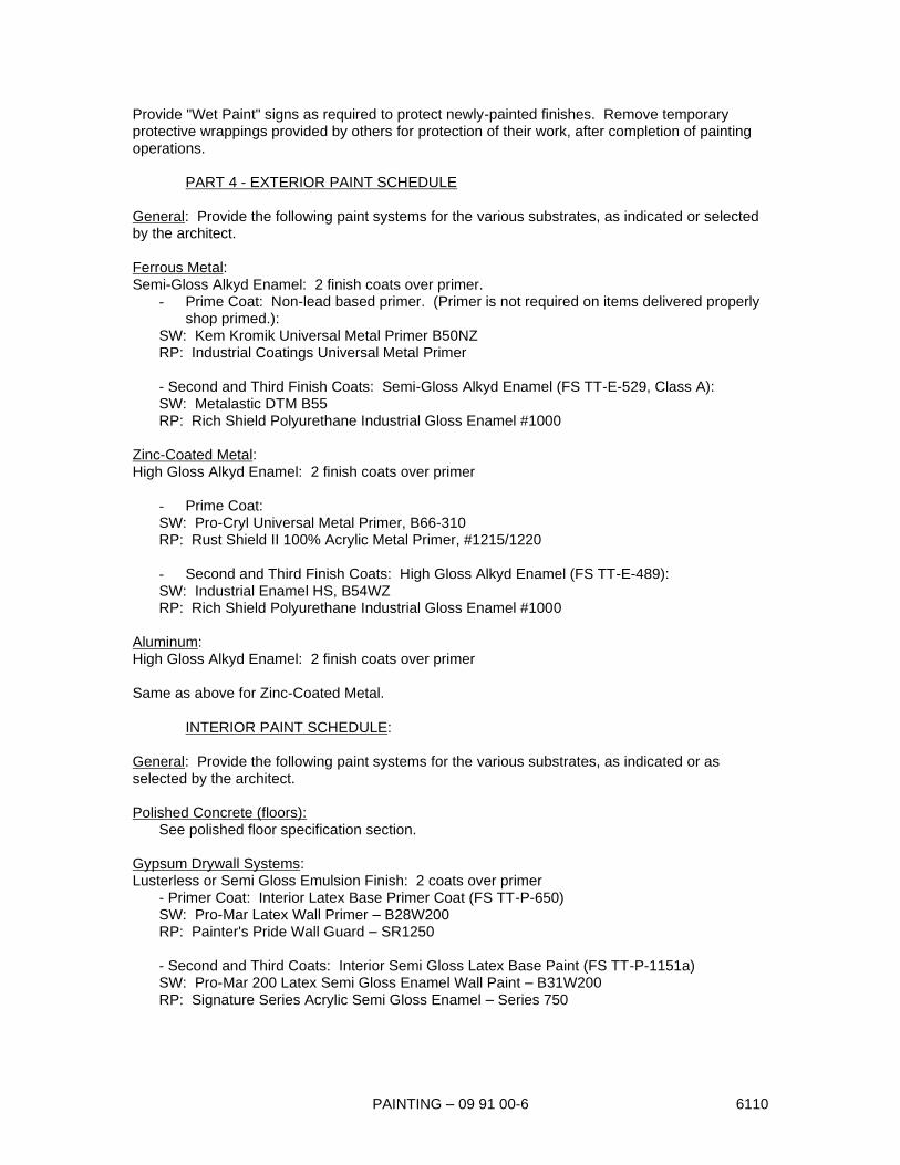
PAINTING – 09 91 00-6 6110
Provide "Wet Paint" signs as required to protect newly-painted finishes. Remove temporary
protective wrappings provided by others for protection of their work, after completion of painting
operations.
PART 4 - EXTERIOR PAINT SCHEDULE
General: Provide the following paint systems for the various substrates, as indicated or selected
by the architect.
Ferrous Metal:
Semi-Gloss Alkyd Enamel: 2 finish coats over primer.
- Prime Coat: Non-lead based primer. (Primer is not required on items delivered properly
shop primed.):
SW: Kem Kromik Universal Metal Primer B50NZ
RP: Industrial Coatings Universal Metal Primer
- Second and Third Finish Coats: Semi-Gloss Alkyd Enamel (FS TT-E-529, Class A):
SW: Metalastic DTM B55
RP: Rich Shield Polyurethane Industrial Gloss Enamel #1000
Zinc-Coated Metal:
High Gloss Alkyd Enamel: 2 finish coats over primer
- Prime Coat:
SW: Pro-Cryl Universal Metal Primer, B66-310
RP: Rust Shield II 100% Acrylic Metal Primer, #1215/1220
- Second and Third Finish Coats: High Gloss Alkyd Enamel (FS TT-E-489):
SW: Industrial Enamel HS, B54WZ
RP: Rich Shield Polyurethane Industrial Gloss Enamel #1000
Aluminum:
High Gloss Alkyd Enamel: 2 finish coats over primer
Same as above for Zinc-Coated Metal.
INTERIOR PAINT SCHEDULE:
General: Provide the following paint systems for the various substrates, as indicated or as
selected by the architect.
Polished Concrete (floors):
See polished floor specification section.
Gypsum Drywall Systems:
Lusterless or Semi Gloss Emulsion Finish: 2 coats over primer
- Primer Coat: Interior Latex Base Primer Coat (FS TT-P-650)
SW: Pro-Mar Latex Wall Primer – B28W200
RP: Painter's Pride Wall Guard – SR1250
- Second and Third Coats: Interior Semi Gloss Latex Base Paint (FS TT-P-1151a)
SW: Pro-Mar 200 Latex Semi Gloss Enamel Wall Paint – B31W200
RP: Signature Series Acrylic Semi Gloss Enamel – Series 750
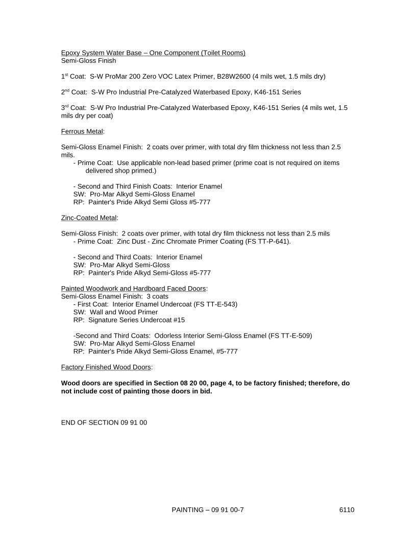
PAINTING – 09 91 00-7 6110
Epoxy System Water Base – One Component (Toilet Rooms)
Semi-Gloss Finish
1st Coat: S-W ProMar 200 Zero VOC Latex Primer, B28W2600 (4 mils wet, 1.5 mils dry)
2nd Coat: S-W Pro Industrial Pre-Catalyzed Waterbased Epoxy, K46-151 Series
3rd Coat: S-W Pro Industrial Pre-Catalyzed Waterbased Epoxy, K46-151 Series (4 mils wet, 1.5
mils dry per coat)
Ferrous Metal:
Semi-Gloss Enamel Finish: 2 coats over primer, with total dry film thickness not less than 2.5
mils.
- Prime Coat: Use applicable non-lead based primer (prime coat is not required on items
delivered shop primed.)
- Second and Third Finish Coats: Interior Enamel
SW: Pro-Mar Alkyd Semi-Gloss Enamel
RP: Painter's Pride Alkyd Semi Gloss #5-777
Zinc-Coated Metal:
Semi-Gloss Finish: 2 coats over primer, with total dry film thickness not less than 2.5 mils
- Prime Coat: Zinc Dust - Zinc Chromate Primer Coating (FS TT-P-641).
- Second and Third Coats: Interior Enamel
SW: Pro-Mar Alkyd Semi-Gloss
RP: Painter's Pride Alkyd Semi-Gloss #5-777
Painted Woodwork and Hardboard Faced Doors:
Semi-Gloss Enamel Finish: 3 coats
- First Coat: Interior Enamel Undercoat (FS TT-E-543)
SW: Wall and Wood Primer
RP: Signature Series Undercoat #15
-Second and Third Coats: Odorless Interior Semi-Gloss Enamel (FS TT-E-509)
SW: Pro-Mar Alkyd Semi-Gloss Enamel
RP: Painter's Pride Alkyd Semi-Gloss Enamel, #5-777
Factory Finished Wood Doors:
Wood doors are specified in Section 08 20 00, page 4, to be factory finished; therefore, do
not include cost of painting those doors in bid.
END OF SECTION 09 91 00
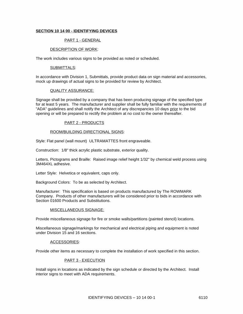
IDENTIFYING DEVICES – 10 14 00-1 6110
SECTION 10 14 00 - IDENTIFYING DEVICES
PART 1 - GENERAL
DESCRIPTION OF WORK:
The work includes various signs to be provided as noted or scheduled.
SUBMITTALS:
In accordance with Division 1, Submittals, provide product data on sign material and accessories,
mock up drawings of actual signs to be provided for review by Architect.
QUALITY ASSURANCE:
Signage shall be provided by a company that has been producing signage of the specified type
for at least 5 years. The manufacturer and supplier shall be fully familiar with the requirements of
"ADA" guidelines and shall notify the Architect of any discrepancies 10 days prior to the bid
opening or will be prepared to rectify the problem at no cost to the owner thereafter.
PART 2 - PRODUCTS
ROOM/BUILDING DIRECTIONAL SIGNS:
Style: Flat panel (wall mount) ULTRAMATTES front engraveable.
Construction: 1/8" thick acrylic plastic substrate, exterior quality.
Letters, Pictograms and Braille: Raised image relief height 1/32" by chemical weld process using
3M464XL adhesive.
Letter Style: Helvetica or equivalent, caps only.
Background Colors: To be as selected by Architect.
Manufacturer: This specification is based on products manufactured by The ROWMARK
Company. Products of other manufacturers will be considered prior to bids in accordance with
Section 01600 Products and Substitutions.
MISCELLANEOUS SIGNAGE:
Provide miscellaneous signage for fire or smoke walls/partitions (painted stencil) locations.
Miscellaneous signage/markings for mechanical and electrical piping and equipment is noted
under Division 15 and 16 sections.
ACCESSORIES:
Provide other items as necessary to complete the installation of work specified in this section.
PART 3 - EXECUTION
Install signs in locations as indicated by the sign schedule or directed by the Architect. Install
interior signs to meet with ADA requirements.
IDENTIFYING DEVICES – 10 14 00-2 6110
Room identification signs are separate from symbols signs and are to be mounted in
combinations as directed by the architect.
Affix signs to surfaces in a manner as recommended by the manufacturer and accepted by the
Architect. Corridor partitions, smoke-stop partitions, horizontal exit partitions, exit enclosures,
and fire walls shall be effectively and permanently identified with stenciling (in concealed areas) in
a manner acceptable to the authority having jurisdiction. Such identification shall be above any
decorative ceiling and in concealed spaces. Suggested wording, "Fire Barrier, Protect All
Openings", or "Fire and Smoke Barrier - Protect All Openings", as applicable.
PART 4 - SIGN SCHEDULE
It is the intent of this specification to require at least one (1) room sign for each and every
room in the new facility.
GROUP TOILET ROOMS
1 each MEN OR WOMEN
Gender symbol & HDCP symbol
ALL OTHER ROOMS OR ROOMS WITHIN ROOMS
1 each * As directed by architect
* Unless room has multiple entry doors from main corridors or from exterior.
END OF SECTION 10 14 00

SOLID PLASTIC COMPARTMENTS/PARTITIONS – 10 21 13-1 8011
SECTION 10 21 13 - SOLID PLASTIC COMPARTMENTS/PARTITIONS
PART 1 - GENERAL
DESCRIPTION OF WORK:
Extent of solid plastic compartments/partitions is indicated on the drawings and herein.
Types of compartments/partitions required for this work include toilet compartments and urinal
screens. All toilet compartments have ceiling supported/suspended pilaster which do not extend
to the floor, except at shower area in dressing rooms.
Coordination: Furnish inserts and anchorages and inform Contractor of any additional blocking
which must be built into other work for installation of toilet partitions and related work.
SUBMITTALS:
In accordance with Section 01 33 00, Submittals, provide product data, shop drawings, sample
color chips for selection and identification in the "color schedule" prepared by the Architect.
WARRANTY/GUARANTY:
Provide 10 year replacement guarantee covering workmanship and material due to delamination,
breakage, rust and corrosion of any and all components of the system.
PART 2 - PRODUCTS
MANUFACTURER:
Subject to compliance with requirements, provide products by Santana Products Inc. or Sanatec,
Inc. Similar products by other manufacturers which meet or exceed this specification will be
considered prior to bids per Section 01 60 00, Products & Substitutions.
MATERIALS:
All materials for panels, doors, tops, pilasters and screens shall be fabricated to 1" thick polymer
resins, Poly-Mar HD (solid plastic), under high pressure forming a single component section
which has a self lubricating plastic glaze that resists marking.
POLY-MAR HD TECHNICAL DATA
Property Value Units ASTM Test Method
Density 0.96+ g/cc D-1505
Tensile Yield 4400 psi D 638
Elongation >600 % D 638
Izod Impact 7.0 ft-lb/in D 256
of notch
Tensile Impact 120 ft-lb/in2 D1822
Brittleness Temp. <-76 oC D 746
Hardness 68 Shore D D2240
Flexural Modulus 220,000 psi D 256
Flammability Index Class B 1" thick E-84-81A
Flame Spread 50
Panel color shall be selected by the Architect from manufacturer's standard color range.

SOLID PLASTIC COMPARTMENTS/PARTITIONS – 10 21 13-2 8011
Pilaster Shoes: ASTM A 167, Type 302/304 stainless steel, not less than 3" high, 20 gage,
finished to match hardware.
Hinges, door/latches, door strikes and wall brackets: Manufacturers standard design of bright-dip
anodized aluminum (6463-T5 Alloy).
Door pulls, door stops and bumper/hooks: Manufacturer's standard design either chromium-
plated non-ferrous cast alloy ("Zamac") or anodized aluminum.
Anchorages and Fasteners: Manufacturer's standard exposed fasteners of stainless steel,
chromium-plated steel, or brass finished to match hardware, with theft-resistant type heads and
nuts. For concealed anchors, use hot-dip galvanized, cadmium-plated, or other rust-resistant
protective-coated steel.
FABRICATION:
Door Dimensions: Unless otherwise indicated, furnish 24" wide in swinging doors for ordinary
toilet stalls and 32" wide (clear opening) out-swinging doors at stalls equipped for use by
handicapped.
Partitions, screens, tops, etc. shall have one-piece sheets with all exposed edges machined to a
.250 radius.
Wall brackets, hinges, door latch and door strike shall be thru bolted with one way sex bolts.
PART 3 - EXECUTION
INSTALLATION:
General: Comply with manufacturer's recommended procedures and installation sequence.
Install panels to be rigid, straight, plumb, and level. Provide clearances of not more than 1/2"
between pilasters and stall panels, and not more than 1" between stall panels and walls. Secure
panels to walls with not less than two stirrup brackets attached near top and bottom of panel.
Locate wall brackets so that holes for wall anchorages occur in masonry or tile joints. Secure
panels to pilasters with not less than three stirrup brackets located to align with stirrup brackets at
wall. Secure panels in position with manufacturer's recommended anchoring devices.
Secure pilasters to adequate blocking above the hard ceiling. Level, plumb, and tighten
installation with devices furnished. Hang doors and adjust so that tops of doors are parallel with
overhead-brace when doors are in closed position.
Secure urinal screens to adequate blocking behind walls with continuous bracket the full height of
the screen.
Accessories: Mount accessories to partition units in accordance with manufacturer's instructions.
Hardware Adjustment: Adjust and lubricate hardware for proper operation. Set hinges on in-
swinging doors to hold open approximately 30 degrees from closed position when unlatched. Set
hinges on out-swinging doors (and entrance swing doors) to return to fully closed position.
END OF SECTION 10 21 13

HIGH IMPACT CORNER GUARDS – 10 26 13-1 1180
SECTION 10 26 13 HIGH IMPACT CORNER GUARDS
PART 1 GENERAL
SUMMARY OF WORK:
Provide all material, including standard accessories and trim, and installation of corner guards where
noted on the drawings.
SUBMITTALS:
In accordance with Section 01 33 00, Submittals, provide product data, shop drawings and color and
pattern samples of sufficient magnitude and detail to fully describe the final application as intended.
PROJECT CONDITIONS:
Wallcovering shall not be stored on site or installed until the building is dried-in; and the HVAC system
operating in order that humidity control is achieved. All windows, doors and openings shall be completed
so as to insure closing for the structure.
PART 2 - PRODUCTS
ACCEPTABLE MANUFACTURERS:
This specification is based on products as manufactured by Construction Specialties, 800-233-8493
(www.c-sgroup.com ). Equal products will be considered prior to bid and in accordance with Section 01
60 00 - Products and Substitutions.
RECESSED MOUNTED CORNER GUARDS:
Cover guard material shall be vinyl acrylic extrusions in nominal wall thickness of .078.
Style shall be the Flush series, ACROVYN FS Series and FS-20R or 1-HR series (full height from base
top to finish ceiling).
ACCESSORIES:
Cover guards shall be provided complete with all necessary accessories including but not limited to
anchors, end caps, adhesives and etc.
INSTALLATION:
Installation shall be in strict accordance with manufacture's written recommendations and as accepted by
the architect thru the submittal review.
END OF SECTION 10 26 13

TOILET AND BATH ACCESSORIES – 10 28 00-1 6110
SECTION 10 28 00 - TOILET AND BATH ACCESSORIES
PART 1 - GENERAL
DESCRIPTION OF WORK:
The work includes the items specified herein and/or shown in the drawings.
SUBMITTALS:
In accordance with Section 01 33 00, Submittals, provide product data for review by the Architect.
PART 2 - PRODUCTS
MANUFACTURER:
Product described herein are manufactured by A & J Washroom Accessories of New Windsor,
New York (914) 562-3332. Similar products by other manufacturers which meet or exceed these
specifications may be considered.
SOAP DISPENSERS (MARK A):
Type: Surface mounted disposable valve cartridge soap dispenser #U103.
PAPER TOWEL DISPENSER (MARK B):
Model: Surface mounted towel dispenser #U180.
MIRRORS (MARK C):
Flush Wall Mounted: #U700 18" X 30" over each lavatory.
Mirror: No. 1 quality, 1/4" polished plate glass silver coated and sealed with electrolytic copper
plating.
TOILET PAPER DISPENSER (MARK D):
Type: Surface Mounted TP dispenser dual jumbo rolls #U834.
GRAB BARS (MARK E):
Type: Concealed flange style #UG30X, Type A
Sizes: One 36" and one 42" Type A at each restroom/stall noted with grab bars and per lengths
as shown at HDCP showers.
RECESSED TAMPON/NAPKIN DISPENSER (MARK F):
Model: Combination Sanitary Napkin/Tampon Dispenser, recessed #U510

TOILET AND BATH ACCESSORIES – 10 28 00-2 6110
SHOWER ROD & CURTAIN (MARK G):
Model: Aluminum curtain track #CR100; white curtain #250A and chains to extend curtain length
to 1" AFF. Track is manufactured by Crowder track.
Size: Bar to be length required to fit opening; curtain to be opening width plus 18".
SURFACE MOUNTED RETRACTABLE SHOWER SEAT (MARK H):
Type: A & J #U933P Phenolic (white), on stainless steel tube frame. Right or left handed as
noted on plan.
PAPER TOWEL DISPOSAL (MARK K):
Model: Recessed waste receptacle with extended, removable receptacle, #U410 at stall (or
individual toilets) and #U412 at group areas.
MOP HOLDER (MARK L):
Model: #UJ12A (26" with 3 holders).
HOOK (MARK M):
Model: Heavy duty hook; UB9.
PART 3 - EXECUTION
GENERAL:
Install each item in accordance with the manufacturer's instructions and as required by current
accessibility codes. Confirm all items, particularly owner furnished items, types and mounting
locations prior to installation of any blocking. Review all heights with Architect prior to installation
and rough-in.
Provide concealed, pressure treated blocking in wall for all items.
Provide fasteners as appropriate to the wall construction.
END OF SECTION 10 28 00

FIRE EXTINGUISHERS & CABINETS – 10 44 00-1 1180
SECTION 10 44 00 - FIRE EXTINGUISHERS & CABINETS
PART 1 - GENERAL
DESCRIPTION OF WORK:
This work includes fire extinguishers, cabinets and wall brackets as located on the drawings.
SUBMITTALS:
In accordance with Division 1, Submittals, provide product data.
PART 2 - PRODUCTS
MANUFACTURER:
Products identified here are manufactured by J.L. Industries, Bloomington Minnesota and Larsen
Manufacturing Co., Minneapolis, Minnesota. Similar products by other manufacturers which meet
or exceed the specification may be considered.
EXTINGUISHERS:
Designation: Cosmic E for wall and cabinet mounting, J-L Model #5.
Style: Multi-purpose, dry chemical type for Class A, B, and C fires.
Rating: Minimum UL rating = 4A-60BC, meeting Underwriter's Standard 299.
Capacity: 10 lb., minimum.
Construction: Seamless steel shell, high test UL hose and horn, red enamel finish.
Features: Machined aluminum valve, visual pressure gauge.
FIRE EXTINGUISHER CABINET:
Fire extinguisher cabinet shall be equal to model C3115 as manufactured by Larsen's
Manufacturing Co.
Mounting type - recessed /or semi recessed and fire rated depending on substrate or wall.
Trim - Flat, brushed satin finished aluminum.
Door: Clear plexiglass door convex bubble with aluminum frame.
Hardware: Provide handle, matching trim, continuous hinge and self adjusting roller catch.
Sign: Provide die cut lettering that adheres to inside of bubble or wall of cabinet.
ACCESSORIES:
Provide wall brackets which hold extinguisher securely in place via ledger and strap with finger
release, where cabinets are not shown required. Provide other materials as necessary to
complete the work.
FIRE EXTINGUISHERS & CABINETS – 10 44 00-2 1180
PART 3 - EXECUTION
Contractor shall install Portable Fire Extinguishers (not cabinets)
with top at 54" above the floor, recessed or flush mounted, in locations as indicated by Architect.
Contractor shall be responsible for filling and servicing Extinguishers until final acceptance.
Upon completion of installation, contractor shall verify that all units have and are maintaining a full
charge, are in proper operating order and bear appropriate inspection tags with expiration date of
not less than 11 months after substantial completion.
END OF SECTION 10 44 00

METAL LOCKERS – 10 51 13-1 6110
SECTION 10 51 13 - METAL LOCKERS
PART 1 - GENERAL
DESCRIPTION OF WORK:
Provide extent of metal lockers as shown on drawings and as specified herein including concrete
bases and accessories for a complete installation.
SUBMITTALS:
In accordance with Section 01 33 00, Submittals, provide product data for review by the Architect.
Also submit listings for combination locks and the locker number, if required.
PART 2 - PRODUCTS:
MANUFACTURER:
Specifications are based on products which can be manufactured by Lyon Metal Products, Inc. or
Republic Storage System Co., Inc. Other manufacturers who can meet or exceed these
specifications, including that implied by reference to the stated manufacturer whether or not
written herein, will be considered.
WARDROBE LOCKERS:
Models: Style Equal to one or more of the following:
Republic Storage Systems Company, Inc.: Mondrian Locker
Lyon Metal Products, Inc.: Quiet II Locker
PENCO Products: Medallion Locker
Materials:
Sheet Steel: Mild cold-rolled and leveled steel, free from buckle, scale, and surface imperfections.
Expanded Metal: 3/4" mesh flattened carbon steel, 13-gage minimum unless otherwise indicated.
Fasteners: Cadmium, zinc, or nickel plated steel; exposed bolt heads, slotless type; self-locking
nuts or locker washers for nuts on moving parts.
Equipment: Hooks and hang rods of cadmium-plated steel or cast aluminum.
Shelving: Cold rolled.
Metal Lumber: Slotted/punched or folded angles, braces, straps, and splice plates.
Sheet Steel: Mild cold-rolled leveled steel free from buckle, scale and surface imperfections.
Fabrication, General:
Construction: Fabricate square, rigid, and without warp, with metal faces flat and free of dents or
distortion. Make all exposed metal edges safe to touch. Weld frame members together to form
rigid, one-piece structure. Weld, bolt or rivet other joints and connections as standard with
manufacturer. Grind exposed welds flush. Do not expose bolts or rivet heads on fronts of locker
doors or frames.
Finishing: Chemically pretreat metal with degreasing and phosphatizing process. Apply baked-on
enamel finish to all surfaces, exposed and concealed, except plates and non-ferrous metal.

METAL LOCKERS – 10 51 13-2 6110
Color: Provide units in color(s) as selected by Architect. Unless otherwise indicated, concealed
parts may be manufacturer's standard neutral color.
Body: Fabricate back and sides of minimum 24 gage steel, with double-flanged connections
extending full height. Form top and bottom of not less than 24 gage steel, with flanged edges.
- Form exposed ends of non-recessed lockers of minimum 16 gage steel.
Door: One-piece, minimum 16 gage sheet steel, flanged at all edges, constructed to prevent
springing when opening or closing. Fabricate to swing 180 degrees unless otherwise indicated.
Ventilation as required: Provide stamped, louvered vents in door face, as follows:
- Double-tier Lockers: Not less than 3 louver openings top and bottom.
Hinges: Heavy-duty, not less than 0.050" thick steel, full-loop, 5-knuckle, tight pin, 2" high. Weld
to inside of frame and secure to door with not less than 2 factory-installed fasteners which are
completely concealed and tamperproof when door is closed. Provide at least 3 hinges for each
door 42" high and over, at least 2 hinges for each door less than 42" high.
Recessed Handle and Latch: Manufacturer's standard design consisting of housing to form
recess for latch lifter and locking devices; non-protruding latch lifter containing strike and eye for
padlock; and automatic, prelocking, pry-resistant latch mechanism with latching action of not less
than 2-point latching.
LOCKER ACCESSORIES:
Locking: Fabricate lockers to receive the following locking devices.
- Spring bolt to receive pad lock
Equipment: Furnish each locker with one double prong ceiling hook and not less than two single-
prong wall hooks, or provide a hang rod in lieu of ceiling hook for 18" deep lockers.
Number Plates: Manufacturer's standard etched, embossed, or stamped, non-ferrous metal
number plates with numerals not less than 3/8" high. Number lockers in sequence as directed by
Architect. Attach plates to each locker door, near top, centered, with at least 2 fasteners of same
finish as number plate.
Continuous Metal Base: Where concrete or integrated bench seat base is not shown, provide
minimum 20-gage cold-rolled steel, fabricated in lengths as long as practicable to enclose base of
lockers without additional fastening devices. Flange bottoms inward 3/4" for stiffening. Factory-
finish metal base to match lockers.
Continuous Sloping Tops: Not less than 20 gage sheet steel, approximately 25 degree pitch, in
lengths as long as practicable but not less than 4 lockers. Provide closures at ends. Finish to
match lockers, unless otherwise indicated.
Separators: Provide horizontal dividers of not less than 16 gage sheet steel between doors of
multiple-tier lockers, to ensure rigidity.
Trim: Provide trim at jambs and head of recessed lockers, consisting of not less than 18 gage
cold-rolled steel, 2" or 3" wide as necessary. Factory-finish trim to match lockers. Secure trim to
lockers with concealed fastening clips.

METAL LOCKERS – 10 51 13-3 6110
Filler Panels: Provide filler panels where indicated, of not less than 16 gage steel sheet, factory-
fabricated and finished to match locker units.
PART 3 - EXECUTION
PREPARATION:
Field Measurements: Take field measurements prior to preparation of shop drawings and
fabrication of special components, when possible, to ensure proper fitting of work. However, allow
for adjustment and fitting of trim and filler panels wherever taking of field measurements before
fabrication might delay work.
INSTALLATION:
Install metal lockers at locations shown in accordance with manufacturer's instructions for plumb,
level, rigid, and flush installation.
Space fastenings about 48" o.c., unless otherwise recommended by manufacturer, and apply
through back-up reinforcing plates where necessary to avoid metal distortion; conceal fasteners
insofar as possible.
Install locker trim, metal base, sloping top units and metal filler panels where indicated, using
concealed fasteners to provide flush, hairline joints against adjacent surfaces.
ADJUST AND CLEAN:
Adjust doors and latches to operate easily without binding. Verify that integral locking devices are
operating properly.
Touch-up marred finishes, but replace units which cannot be restored to factory-finished
appearance. Use only materials and procedures recommended or furnished by locker
manufacturer.
END OF SECTION 10 51 13

SHELVING – 10 67 00-1 6110
SECTION 10 67 00 - SHELVING
PART 1 - GENERAL
DESCRIPTION OF WORK:
Provide shelving units for use in custodial closets and similar locations, where shown on the
drawings.
SUBMITTALS:
In accordance with Section 01 33 00, submittals, provide product data for review by Architect.
PART 2 - PRODUCTS
MANUFACTURER:
Products described herein are manufactured by PENCO PRODUCTS, Oaks, Pennsylvania.
Products by other manufacturers which meet or exceed these specifications will be considered
prior to bids per section 01 60 00.
SHELVING UNITS:
Type: Heavy duty industrial grade steel shelving.
Size: 36" width, 18" depth (unless noted otherwise)
Number of Shelves: 7 shelves
Construction: Posts, roll formed box posts punched on 1" centers, offset
angle posts at rear
Clips, heavy duty compression clips, 14 gauge, zinc plated
Shelves, 1 3/16" high flange with (2) 7/16" return flanges
and welded corners, 18 gauge, positive shelf seating
Sides and back panels, 24 gauge steel, punched for bolting
ACCESSORIES:
Provide fasteners, panels, braces, etc. as required for a sturdy, free standing rigid shelf unit.
PART 3 - EXECUTION
GENERAL:
Erect shelving units in accordance with manufacturers recommendations.
Set in place as shown on drawings.
Adjust and level shelving unit to prevent rocking and sway and attach to wall stud with two
screws/fasteners per shelving unit.
END OF SECTION 10 67 00

ALUMINUM CANOPIES (CUSTOM) – 10 73 13-1 6110
SECTION 10 73 13 - ALUMINUM CANOPIES (CUSTOM)
PART 1 GENERAL
DESCRIPTION OF WORK:
Furnish and install the suspended end aluminum at the main entry door(s) where detailed on the
drawings.
SUBMITTALS:
In accordance with Section 01 33 00, Submittals, of this specification provide shop drawings prepared for
this work, material samples, color samples and product data.
QUALITY ASSURANCE:
Shop drawings shall identify all materials and components with details for installation for this work. Live
and dead loads affecting this structure shall be clearly shown. All product members shall be sized to
meet ASCE 7-02, 150 mph min. wind speed, and other code requirements for lateral, dead and live loads
per Florida Building Code. All drawings submitted by the manufacturer shall be signed and sealed by a
Florida registered structural engineer.
Manufacturer and installer shall submit evidence that for 5 years minimum they have been in business to
manufacturer and install fixed aluminum walkway covers.
PART 2 - PRODUCTS
APPROVED MANUFACTURER:
The drawings and specifications are based on products manufactured by DITTMER Architectural
Aluminum of Winter Springs, Florida. Similar or better products of another manufacturer will be
considered prior to bid. Other manufacturers shall submit a letter of request for consideration and product
literature in accordance with Section 01 60 00, Products and Substitutions.
GENERAL:
Aluminum Canopy shall be entirely of anodized aluminum extrusions. Structure shall consist of heli-arc
welded members and a soffit deck of interlocking anodized aluminum extrusions with fascia gutters for
the side entries. The structure shall be capable of sustaining severe icing, hail, and hurricane winds.
MATERIALS:
All sections shall be 6063 alloy heat-treated to a T-6 temper. Deck screws shall be type 18-8 stainless
steel, sealed with neoprene "O" ring beneath stainless steel; trim rivets may be aluminum.
INTERNAL DRAINAGE:
Water flow is directed from deck to fascia or rear gutter for discharge to a downspout at side(s).
FINISH:
Shall be equal to a Kynar 500 on exposed components. Concealed areas may be baked enamel. All
colors shall be selected by the Architect from the full range of colors available, standard and premium
grades.
ALUMINUM CANOPIES (CUSTOM) – 10 73 13-2 6110
PART 3 - EXECUTION
GENERAL:
The manufacturer/installer shall visit the site to confirm the contractors schedule and readiness to
undertake installation of this work. Once the manufacturer/installer commences with the work, it shall be
understood that he accepts the conditions of the site.
The manufacturer/installer shall verify all dimensions for the installation in the field.
CLEAN-UP:
Manufacturer/installer shall clean-up the installation and work site on a daily basis.
END OF SECTION 10 73 13

RESIDENTIAL KITCHEN EQUIPMENT – 11 31 00-1 6110
SECTION 11 31 00 - RESIDENTIAL KITCHEN EQUIPMENT
PART 1 - GENERAL
DESCRIPTION OF WORK:
Extent of residential kitchen equipment required is indicated on the drawings and schedules
herein.
Types of kitchen equipment required include an under counter dishwasher.
Plumbing and electrical services to the above unit(s) are specified in Divisions 22 and 26.
Certification Labels:
Provide residential equipment which complies with standards and bears certification lables as
follows:
Energy Ratings: Provide energy guide labels with energy cost analysis (annual operating costs)
and energy information as required by Federal Trade Commission.
UL Standards: Provide residential equipment with UL labels.
ANSI Standards: Provide gas-burning residential equipment with American Gas Association
(AGA) seal of approval, complying with ANSI Z21-Series.
Uniformity: To greatest extent possible, provide residential equipment by single manufacturer for
entire project.
SUBMITTALS:
In accordance with section 01 33 00, Submittals, provide product data and color samples/chips for
review by the architect.
PART 2 - PRODUCTS
MANUFACTURERS:
Subject to compliance with requirements, provide the following (or equal): Whirlpool 24”, 55
decibel, built-in, Model #WDT710PAYM
Colors:
Provide manufacturer's standard stainless steel front panel.
Wherever residential equipment by more than one manufacturer is installed in same space,
provide units with color matching largest equipment item, unless otherwise accepted by architect.
PART 3 - INSTALLATION
Comply with manufacturer's written instructions and recommendations for the locations noted.
Notify architect if a discrepancy exists which would not allow proper installation prior to bidding.
Built-In Equipment: Securely anchor units to supporting cabinetry or countertops with concealed
fasteners. Verify that clearances are adequate for proper functioning and rough openings are
completely concealed.

RESIDENTIAL KITCHEN EQUIPMENT – 11 31 00-2 6110
Freestanding Equipment: Place units in final locations after finishes have been completed in each
area. Verify clearances are adequate for proper operation of equipment.
Utilities: Refer to Divisions 22, 23 and 26 for plumbing and electrical requirements.
END OF SECTION 11 31 00

FOOD SERVICE EQUIPMENT – 11 40 30-1 1121
SECTION 11 40 30 - FOOD SERVICE EQUIPMENT
PART 1 - GENERAL
DESCRIPTION OF WORK:
Extent of food service equipment is indicated on drawings and by provisions of this section,
including schedules and equipment lists associated with either drawings or this section.
Types of equipment/facilities required for project include the following:
- Stainless Steel Tables and lockable cabinets.
- Stainless Steel Range Hood
QUALITY ASSURANCE:
Fabricator/Installer: Where indicated units of equipment require custom fabrication, provide units
fabricated by shops which are skilled and with a minimum of 5 years of experience in similar
work. Where units cannot be fully shop fabricated; fabrication shop shall complete fabrication
work at project site.
SUBMITTALS:
In accordance with Section 01 33 00, Submittals, provide: product data (with rough-in dimension)
on each item of equipment; shop drawings with plans, elevations, and details of custom
fabricated units; rough-in drawings for use in the field; samples for color/finish selection by the
architect; and maintenance manuals for each item of equipment.
PART 2 - PRODUCTS
Approved Manufacturers: For the purpose of establishing type and quality, these specifications
have been written based on various manufacturers of individual items. Similar products by other
manufacturers which meet or exceed these specifications may be considered upon receipt of
submittals in compliance with Section 01600, Products and Substitutions, and Section 01340,
Shop Drawings, Product Data and Samples.
CUSTOM FABRICATED STAINLESS STEEL TABLES:
Manufacturer: Metal Masters Foodservice Equipment Co., Inc. (800) 441-8440
Construction Materials Series: SEB.
- Top: 16 gauge stainless steel, type 304.
- Undershelf: 18 gauge stainless steel, type 430.
- Legs: 1-5/8" O.D. 16 gauge, tubular stainless steel, galvanized gussets, 1" adjustable, high-
impact plastic feet.
Features:
- Integral stainless steel backsplash as detailed on drawings.
- Top reinforced with welded-on hat channels.
- Sound-deadening between top and channels.
- Rolled or squared edges at front and sides where not adjacent to walls or other items.
- Uni-lock gusset system reinforcement to reduce lateral movement.
Sinks and Plumbing Fixtures: Provide for integration of sinks and plumbing fittings noted on plans and/or specified in Div. 22 Plumbing.

FOOD SERVICE EQUIPMENT – 11 40 30-2 1121
Electrical Service Outlets: Provide for integration of electrical service outlets where noted on
plans and/or specified in Div. 26 Electrical. Outlets shall be placed in vertical backsplash.
Coordinate height of splash to receive outlet.
Sizes: Depth, length and heights shall be as shown on the drawings.
ENCLOSED STAINLESS STEEL WORK TABLES/ CABINETS
Manufacturer: Eagle food service equipment as manufactured by Metal Masters Food service
Equipment Co., Inc. (800) 441-8440.
Construction: Stainless steel 16 gauge, type 304; 16 gauge stainless steel top; satin finish
stainless steel, all-welded design. Sound-deadened between top and frames.
Features:
- 1-5/8" min. O.D. diameter stainless steel legs.
- 1" adjustable feet.
- 1-1/2" rolled or square front edge.
- Stainless steel integral backsplash at all side and back walls, min. 4" height.
- Where cabinet located at a thru-the-wall serving opening, provide a continuous thru-the-
wall stainless steel top without visible seams; see drawings.
- Provide key lock stainless steel pass by doors with finger grips with nylon rollers and
stainless steel guides, rubber stop at both ends.
- Cabinet base sides and back shall be stainless steel where exposed.
- Provide at least one (1) intermediate stainless steel shelf of not less than 18 gauge.
Sizes: Width, length and height shall be as shown on the drawings.
STAINLESS STEEL RANGE HOOD
Comply with NFPA 96 including Appendix A, and furnish and install a complete hooded exhaust
system. Include complete detailed shop drawings for review by the engineer and architect.
Provide a hooded exhaust system which has been designed to pull only 20% of the interior
conditioned air while the remaining 80% of required exhaust is made up with a filtered fan
supplying unconditioned air from the outside as an integral part of the hood design.
For the purposes of defining quality, these specifications are based on model MBS hood and
model MFP supply and exhaust fan components and shall be U.L. rated.
Hood system designer shall comply with all codes, laws and ordinances in for this building.
Provide a hood constructed of 18 GA stainless steel cold rolled with liquid tight welded seams
and polished.
One incandescent vapor proof light fixture shall be provided for each 3 feet of length.
Filter holding racks shall be of low air leakage by design allowing for easy removal and
replacement of filters.
Exhaust fans shall be designed and provided which meet with the air extraction requirements for
the size hood as indicated and complying with all codes in force.
Supply air fans shall be designed to provide 80% of the outside air required by system size and
codes in force.

FOOD SERVICE EQUIPMENT – 11 40 30-3 1121
Provide opposed blade type replacing dampers for the supply air inlets to the hood.
Curbs shall be designed paying strict attention to wind design pressures, impact resistance and
other requirements of codes and local ordinances.
Hood shall be designed to provide adequate coverage for the equipment installed.
Completed installation will be tested by a trained representative of a testing company
experienced at the testing of said equipment.
Equipment manufacturer shall provide templates to General Contractor for preparations of roof,
deck etc.
Provide removable grease filters of aluminum mesh 2" thick, with drip-channel gutters, drains and
collection basins.
Exhaust duct shall be 18 gauge stainless steel with finish to match hood finish where exposed.
Carbon steel of 16 gauge thickness to be used where concealed. All seams welded and all ducts
installed and fire protected in accordance with applicable codes.
Fan package shall be furnished with a pre-wired control center and shall include, but not be
limited to, fused disconnect switch, fused motor protection, magnetic motor selectors with three
thermal overloads, fused control transformers and terminal strip. Panel shall be arranged for a
single power service connection. Provide switches with pilot lights on exhaust hood for
independent exhaust fan operation and combination supply fans and exhaust fan operation.
Switches shall be mounted on the wall at ADA Ht. in a location as approved by the Architect. Fan
control shall be interlocked with fire protection system. All power and control wiring shall be
under this division, installed in accordance with the requirements of Division 16-Electrical.
Provide and install a complete dry chemical protection system in accordance with the
requirements of U1 NFPA-17 and applicable state and local codes. System shall include remote
manual release, micro switches to shut down hood ventilation, de-energize electric relays to
cooking equipment power supply and interlock with fire alarm system. Horizontal fire protection
piping within the hood shall be concealed. Control and interlock wiring shall be under this division
in accordance with the requirements of Division 16-Electrical. Submit complete shop drawings
for review and approval. Manufacturer's representative of the fire protection system shall
supervise the installation and testing of the system. It is desirable that the control box for this
system be attached to and a part of the kitchen hood with a remote fan and light switch control
mounted on nearby wall. Confirm location with Architect if not shown on the plans.
PART 3 - EXECUTION
INSPECTION AND PREPARATION:
Rough-In Work: Installer of food service equipment must examine drawings and assist in precise
location of roughed-in mechanical and electrical services, and installation locations in floors,
walls, columns and ceilings, and conditions under which the work is to be installed; and must
verify dimensions of services and substrates before fabricating the work. Notify Contractor in
writing of unsatisfactory locations and dimensions of other work, and of unsatisfactory conditions
for proper installation of food service equipment. Do not proceed with fabrication and installation
until unsatisfactory dimensions and conditions have been corrected in a manner acceptable to
Installer.
Coordination: Equipment manufacturer shall provide templates to General Contractor for
penetrations of roof deck for hood, etc.

FOOD SERVICE EQUIPMENT – 11 40 30-4 1121
INSTALLATION:
Service Lines and Equipment Connections: Comply with applicable requirements of Division-15
sections for piping connections and piping systems. Comply with applicable requirements of
Division-16 sections for electrical work including equipment connections.
Set each item of nonmobile and nonportable equipment securely in place, leveled and adjusted to
correct height. Anchor to supporting substrate where indicated and where required for sustained
operation and use without shifting or dislocation. Conceal anchorages where possible. Adjust
counter tops and other work surfaces to a level tolerance of 1/16" maximum offset, and maximum
variation from level or indicated slope of 1/16" per ft.
Complete field assembly joints in the work (joints which can not be completed in shop) by
welding, bolting-and-gasketing, or similar methods as indicated. Grind welds smooth and restore
finish. Set or trim gaskets flush, except for "T" gaskets as indicated.
Treat enclosed spaces (inaccessible after equipment installation) by covering horizontal surfaces
with powdered borax as a rate of 4 oz. per sq. ft.
Install closure plates and strips where required, with joints coordinated with units of equipment.
Install sealants and gaskets all around each unit to make joints air-tight, waterproof, vermin-proof
and sanitary for cleaning purposes. In general, make sealed joints not less than 1/8" wide, and
stuff with backer rod to shape sealant bead properly, at 1/4" depth. Shape exposed surfaces of
sealant slightly concave, with edges flush with faces of materials at joint. At internal-corner joints,
apply sealant or gaskets to form a sanitary cove, of not less than 3/8" radius. Provide sealant-
filled or gasketed joints up to 3/4" joint width; metal closure strips for wider joints, with sealant
application each side of strips. Anchor gaskets mechanically or with adhesives to prevent
displacement.
CLEANING, RESTORING FINISHES:
After completion of installation, and completion of other major work in food service areas, remove
protective coverings, if any, and clean food service equipment, internally and externally. Restore
exposed and semi-exposed finishes to remove abrasions and other damages; polish exposed-
metal surfaces and touch-up painted surfaces. Replace work which can not be successfully
restored.
END OF SECTION 11 40 30

MANUAL PROJECTION SCREENS – 11 52 13-1 6110
SECTION 11 52 13 - MANUAL PROJECTION SCREENS
PART 1 - GENERAL
DESCRIPTION OF WORK:
Extent of projection screens is shown on drawings and specified and scheduled herein.
Types of projection screens required include:
- Front projection screens, manually operated.
QUALITY ASSURANCE:
Provide each type of projection screen as a complete unit produced by a single manufacturer,
including necessary mounting brackets, accessories, fittings and fastenings.
FIRE PERFORMANCE CHARACTERISTICS:
Provide projection screen fabrics identical to those materials which have undergone testing and
passed requirements for flame resistance as indicated below:
NFPA 701 per small scale test.
Federal Standard 191A/5903 for test method. FS GG-S-00172D(1) for flame resistance.
MILDEW RESISTANCE:
Provide mildew resistant screen fabrics as determined by Federal Standard 191A/5960.
SUBMITTALS:
In accordance with Division 1, Submittals, provide product data, shop drawings and color chips
for review.
DELIVERY, STORAGE & HANDLING:
Do not deliver projection screens until building is enclosed and ready for screen installation.
Protect screens from damage during delivery, handling, storage and installation.
PART 2 - PRODUCTS
MANUALLY-OPERATED FRONT PROJECTION SCREENS:
General: Provide manufacturer's standard units consisting of case, screen, mounting
accessories and other components as required for a complete installation and complying with
descriptive requirements indicated below.
Spring-Roller-Operated Projection Screens: Units designed and fabricated for wall or ceiling
installation and complying with the following requirements.
Screen Case: Fabricated in one piece from not less than 22-gage steel with flat back design,
vinyl-covered or baked-enamel finish as selected by the Architect, and end caps with integral
roller brackets and furnished with universal mounting brackets in finish matching end caps to
enable attachment to wall or ceiling.
MANUAL PROJECTION SCREENS – 11 52 13-2 6110
Screen: Mildew and flame resistant glass fiber fabric with vinyl-coated viewing surface complying
with requirements indicated below, the top edge mounted on, and securely anchored to a 3"
diameter rigid steel spring roller and bottom edge formed into a pocket holding a tubular metal
slat, with ends of rod protected by plastic caps containing a screw-attached saddle and pull.
Size of Viewing Surface: 70" X 70"
Type of Viewing Surface: Matte white with minimum gain characteristics complying with FS GG-
S-00172D(1) for Type A screen surface.
Edge Treatment: Black masking borders.
Accessories: Provide pull cord, wall brackets and other miscellaneous accessories as required to
install projection screens at heights and locations noted.
Products: Subject to compliance with requirements, manufacturers offering products which may
be incorporated into the work include those listed below. Other manufacturers may be
considered prior to acceptance of bids.
"Vidio" B; Da-Lite Screen Co., Inc.
Luma 2; Draper Shade & Screen Co.
200 Series; Bredford Manufacturing, Ltd.
PART 3 - EXECUTION
INSTALLATION:
Install projection screen units and accessories at locations shown in accordance with
manufacturer's instructions. Install level, plumb, secure, and recessed at proper height.
Coordinate with other trades to provide blocking for securing projection screen units to finished
surfaces. Repair or replace damaged units as directed by Architect.
Provide protections for installed units so that they will be in satisfactory operating condition,
without damage at completion of project.
END OF SECTION 11 52 13

WINDOW TREATMENT – 12 21 10-1 8011
SECTION 12 21 10 - WINDOW TREATMENT
PART 1 - GENERAL
DESCRIPTION OF WORK:
The work includes providing window treatment in the forms as specified herein or shown on the drawing.
A brief summary of those types included are listed but may not be limited to the following.
QUALITY ASSURANCE
Provide complete assemblies produced by one manufacturer for each type required including hardware,
accessory items, mounting brackets and fastenings.
SUBMITTALS:
In accordance with Division 1, "Submittals" provide : shop drawings showing installation details for each
type of installation; product data; color selection chips and a sample of each type of blind and track.
JOB MOCK-UP:
Provide field installed mock-up to confirm actual installation confirmation for approval by Architect.
COLOR:
As selected by the Architect from manufacturer's standard range of colors. Manufacturers with limited
color selections, as judged solely by the architect, may be subject to rejection.
WARRANTY:
Provide lifetime warranty covering headrail (track system mechanism and components) for heavy duty
track and three year warranty on standard duty track system.
EXTRA STOCK:
Provide the owner at close of project, with additional blades equal to 3% of the total, in lengths equal to
the largest length used on the project.
PART 2 - PRODUCTS
VERTICAL BLINDS:
Provide vertical blind units complete with track system (headrail), operating mechanisms, louver blades
and accessories as required for a complete installation and as identified herein.
Track system shall be from extruded aluminum channel with end caps to accommodate the type of
operating mechanism as indicated herein.
Heavy Duty Track: with a minimum width of 1 15/16" and a minimum height of 1 3/8".
Track finish shall be clear anodized aluminum AA-C22A21.
Provide bead chain or wand operation pivot mechanism for full synchronous 180 degree geared rotation
of each louver blade.
(Note: Cord linkages are not acceptable as the rotating mechanism.)
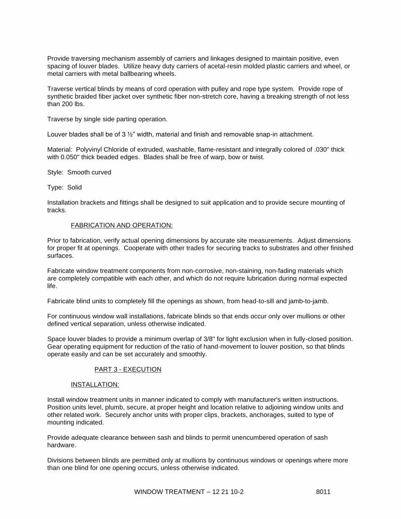
WINDOW TREATMENT – 12 21 10-2 8011
Provide traversing mechanism assembly of carriers and linkages designed to maintain positive, even
spacing of louver blades. Utilize heavy duty carriers of acetal-resin molded plastic carriers and wheel, or
metal carriers with metal ballbearing wheels.
Traverse vertical blinds by means of cord operation with pulley and rope type system. Provide rope of
synthetic braided fiber jacket over synthetic fiber non-stretch core, having a breaking strength of not less
than 200 lbs.
Traverse by single side parting operation.
Louver blades shall be of 3 ½” width, material and finish and removable snap-in attachment.
Material: Polyvinyl Chloride of extruded, washable, flame-resistant and integrally colored of .030" thick
with 0.050" thick beaded edges. Blades shall be free of warp, bow or twist.
Style: Smooth curved
Type: Solid
Installation brackets and fittings shall be designed to suit application and to provide secure mounting of
tracks.
FABRICATION AND OPERATION:
Prior to fabrication, verify actual opening dimensions by accurate site measurements. Adjust dimensions
for proper fit at openings. Cooperate with other trades for securing tracks to substrates and other finished
surfaces.
Fabricate window treatment components from non-corrosive, non-staining, non-fading materials which
are completely compatible with each other, and which do not require lubrication during normal expected
life.
Fabricate blind units to completely fill the openings as shown, from head-to-sill and jamb-to-jamb.
For continuous window wall installations, fabricate blinds so that ends occur only over mullions or other
defined vertical separation, unless otherwise indicated.
Space louver blades to provide a minimum overlap of 3/8" for light exclusion when in fully-closed position.
Gear operating equipment for reduction of the ratio of hand-movement to louver position, so that blinds
operate easily and can be set accurately and smoothly.
PART 3 - EXECUTION
INSTALLATION:
Install window treatment units in manner indicated to comply with manufacturer's written instructions.
Position units level, plumb, secure, at proper height and location relative to adjoining window units and
other related work. Securely anchor units with proper clips, brackets, anchorages, suited to type of
mounting indicated.
Provide adequate clearance between sash and blinds to permit unencumbered operation of sash
hardware.
Divisions between blinds are permitted only at mullions by continuous windows or openings where more
than one blind for one opening occurs, unless otherwise indicated.

WINDOW TREATMENT – 12 21 10-3 8011
Isolate metal parts from concrete and mortar to prevent galvanic action. Use tape or thick coating or
other means recommended by manufacturer to effect separation.
Protect installed units to ensure their being in operating condition, without damage, blemishes, or
indication of use at completion of project. Repair or replace damaged units as directed by the Architect.
END OF SECTION 12 21 10

RUGS AND MATS – 12 48 00-1 1150
SECTION 12 48 00 - RUGS AND MATS
PART 1 - GENERAL
DESCRIPTION OF WORK:
Furnish and install where shown on the drawings the rugs and mats described in this
specification.
SUBMITTALS:
In accordance with specification Section 01 33 00, Submittals, provide product data, samples, and
color chips for review and color selection by the Architect.
PART 2 - PRODUCTS
ACCEPTABLE MANUFACTURERS:
The drawings and specifications are based on products manufactured by the AMARCO (American
Mat & Rubber Co.), (866) 688-6287. Similar products of equal or better quality will be considered
by the Architect ten (10) days prior to the bid date.
ROLL-UP MATS:
Style: AL-TRACK 650 Model AT-650
Construction:
Rails: Aluminum, extruded profile, assembled at 1 7/8 inches on center.
Hinges: Extruded vinyl, perforated continuous hinge and support cushion, positively secured
between aluminum rails, slotted perforations for drainage.
Tread Inserts: Aluminum with abrasive insert (AA), extruded 1 inch wide, spaced 1 1/2 inches on
center, crowned profile with 13/16 inch abrasive mineral grit surface for slip resistance, minimum
static coefficient of friction 1.14 dry, 1.20 wet.
Overall Depth: 5/8 inch
Colors: Selected from full range of manufacturer’s standard colors by Architect.
Mat Frame:
Material: Aluminum extrusion
Style: For recessed installation
Finish: Selected from full range of manufacturer’s standard colors
PART 3 - EXECUTION
INSTALLATION:
Field Measurements: Actual recess openings shall be checked and accurate field measurements
shall be taken. Measure overall width (left to right) and overall length (front to back) at three
points. Measure the diagonals (to determine squareness) before fabricating mats. Measurements shall be included on shop drawings.

RUGS AND MATS – 12 48 00-2 1150
Installations: Recess shall be cleaned thoroughly by removing construction debris. Contractor
shall check for uniform depth and install mat or grate per shop drawing.
END OF SECTION 12 48 00
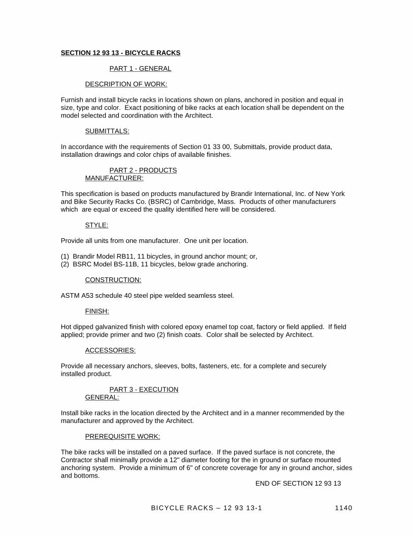
BICYCLE RACKS – 12 93 13-1 1140
SECTION 12 93 13 - BICYCLE RACKS
PART 1 - GENERAL
DESCRIPTION OF WORK:
Furnish and install bicycle racks in locations shown on plans, anchored in position and equal in
size, type and color. Exact positioning of bike racks at each location shall be dependent on the
model selected and coordination with the Architect.
SUBMITTALS:
In accordance with the requirements of Section 01 33 00, Submittals, provide product data,
installation drawings and color chips of available finishes.
PART 2 - PRODUCTS
MANUFACTURER:
This specification is based on products manufactured by Brandir International, Inc. of New York
and Bike Security Racks Co. (BSRC) of Cambridge, Mass. Products of other manufacturers
which are equal or exceed the quality identified here will be considered.
STYLE:
Provide all units from one manufacturer. One unit per location.
(1) Brandir Model RB11, 11 bicycles, in ground anchor mount; or,
(2) BSRC Model BS-11B, 11 bicycles, below grade anchoring.
CONSTRUCTION:
ASTM A53 schedule 40 steel pipe welded seamless steel.
FINISH:
Hot dipped galvanized finish with colored epoxy enamel top coat, factory or field applied. If field
applied; provide primer and two (2) finish coats. Color shall be selected by Architect.
ACCESSORIES:
Provide all necessary anchors, sleeves, bolts, fasteners, etc. for a complete and securely
installed product.
PART 3 - EXECUTION
GENERAL:
Install bike racks in the location directed by the Architect and in a manner recommended by the
manufacturer and approved by the Architect.
PREREQUISITE WORK:
The bike racks will be installed on a paved surface. If the paved surface is not concrete, the
Contractor shall minimally provide a 12" diameter footing for the in ground or surface mounted
anchoring system. Provide a minimum of 6" of concrete coverage for any in ground anchor, sides
and bottoms.
END OF SECTION 12 93 13

METAL BUILDING SYSTEM – 13 34 19-1 6120
SECTION 13 34 19 METAL BUILDING SYSTEM
PART 1 - GENERAL
DESCRIPTION OF WORK:
The building is a NUCOR System, pre-engineered single story, high bay plus lean-to areas, rigid
frame metal type of length, width, eave height and roof pitch indicated. It has been procured by
Blue Origin and fabrication drawings have been approved.
QUALITY ASSURANCE:
Design Criteria: Design loads are indicated on the fabrication drawings.
PART 2 - PRODUCTS
PAINT & COATING:
Primary Members:
Shop Primer for Ferrous Metal: FS TT-P-645; fast-curing lead-free, "universal" primer compatible
with finish paint.
Shop Primer for Galvanized Metal Surfaces: FS TT-P-641; zinc dust-zinc oxide primer compatible
with substrate.
Secondary Members:
Shop Painting: Clean surfaces of loose mill scale, rust, dirt, oil, grease, and other matter. Follow
procedures of SSPC-SP3 for power tool cleaning, SSPC-SP7 for brush-off blast cleaning, and
SSPC-SP1 for solvent cleaning.
Finish Coating:
Refer to architectural drawing finish legend and to Section 09 91 00 and paint all primed surfaces
which will remain exposed to view.
ACCESSORIES AND MISCELLANEOUS:
Thermal Roof Insulation: Consists of a glass fiber blanket double layer banded/roof insulation
faced with 2 mil. vinyl and .0007" thick aluminum foil reinforced with glass fiber scrim, UL
flamespread classification of 25 or less.
PART 3 - ERECTION
Framing: Erect framing true to line, level and plumb, rigid and secure. Level base plates to an
even plane with full bearing to supporting structures, set with double-nutted anchor bolts. Use
non-shrinking grout to obtain uniform bearing and maintain a level base line elevation. Moist cure
grout for 7 days after placement.
Purlins and Girts: Provide rake or gable purlins with tight fitting closure channels and fascias.
Locate and space wall girts to suit door and window arrangements and heights. Secure to
framing and hold rigidly to a straight line by sag rods.
Bracing: Provide diagonal rod or angle bracing in roof and sidewalls or movement resisting
frames as indicated.

METAL BUILDING SYSTEM – 13 34 19-2 6120
Framed Openings: Provide shapes of proper design and size to reinforce openings and carry
loads and vibrations imposed, including equipment furnished under mechanical or electrical work.
Securely attach to building structural frame.
Roofing and Siding: Nest sidelap joints. Lap sheets one full rib corrugation. Apply panels and
associated items for neat and weathertight enclosure. Avoid application not true to line. Provide
weatherseal under ridge cap. Flash and seal roof panels at eave and rake with rubber or
neoprene closures. Protect finishes from damage.
Standing Seam Roof Panel System: Fasten panels to purlins with concealed clips. Install clips at
each support using self-drilling fasteners. At end laps install tape caulk between panels. Install
factory-caulked cleats at standing seam joints. Machine seam cleats to panels to provide a
weather-tight joint.
Thermal Insulation: Install concurrently with roof panels, straight and true in one-piece lengths
with both sets of tabs sealed to provide a vapor barrier. Locate on the underside of roof sheets,
extending across the top flange of purlin members, held taut and snug to roofing panels with
retainer clips. Install retainer strips at each longitudinal joint nesting with roof rib.
Translucent Panels: Attach to framing in accordance with the manufacturer's instructions. For
roof panels provide 6" end laps and side laps of not less than 1 1/2 corrugations. For siding panels
provide 4" end laps and side laps of not less than 1 1/2 corrugations. Align horizontal laps with
adjacent panels. Seal intermediate end laps and side laps with mastic.
Wall Sheets: Apply sealant continuously between metal base channel (sill angle) and concrete
and elsewhere as necessary for waterproofing. Handle and apply sealant and back-up in
accordance with the manufacturer's recommendations.
- Align bottoms of wall panels and fasten with blind rivets, bolts or self-tapping screws. Fasten
flashings, trim around openings, and similar elements with self-tapping screws. Fasten window
and door frames with machine screws or bolts. When building height requires two rows of panels
at gable ends, align lap of gable panels over wall panels at eave height.
- Install screw fasteners with power tool having controlled torque adjusted to compress neoprene
washer tightly without damage to washer, screw threads, or panels. Install screws in predrilled
holes.
Sheet Metal Accessories: Install gutters, downspouts, louvers, ventilators and other sheet metal
accessories in accordance with manufacturer's recommendations. Adjust operating mechanism
for precise operation.
Hollow Metal Doors and Frames: Install straight, plumb and level. Set doors with 1/8" maximum
clearance between door and frame at jambs and head, and 3/4" max. between door and floor.
Adjust hardware for proper operation.
Overhead Coiling Doors: Set doors and operating equipment in accordance with manufacturer's
instructions. Adjust for proper operation.
Dissimilar Materials: Keep aluminum surfaces from direct contact with ferrous metal or other
incompatible materials by applying one coat of zinc chromate primer to the other material followed
by two coats of aluminum paint, SSPC-Paint 10.
- Backpaint aluminum surface where it is impractical to paint the other surface.

METAL BUILDING SYSTEM – 13 34 19-3 6120
Field Painting: Apply finish coats to factory primed and other items to receive paint in accordance
with drawing finish tags Section 09 91 00, Painting.
END OF SECTION 13 34 19

VERTICAL WHEELCHAIR LIFTS – 14 42 16-1 6120
SECTION 14 42 16 – VERTICAL WHEELCHAIR LIFTS SCOPE: Provide wheelchair lift where shown on drawings in an operable manor as clarified by the manufacturer and approving authorities in the State of Florida. SUBMITTALS: Submit under provisions of Section 01 33 00. Product Data: Manufacturer's data sheets on each product to be used, including:
Submit manufacturer's installation instructions, including preparation, storage and handling requirements.
Include complete description of performance and operating characteristics.
Show maximum and average power demands.
Shop Drawings:
Show typical details of assembly, erection and anchorage.
Include wiring diagrams for power, control, and signal systems.
Show complete layout and location of equipment, including required clearances and coordination with shaftway.
Selection Samples: For each finished product specified, provide two complete sets of color chips representing manufacturer's full range of available colors and patterns. QUALITY ASSURANCE: Manufacturer Qualifications: Firm with minimum 10 years experience in manufacturing of vertical platform lifts, with evidence of experience with similar installations of type specified. Installer Qualifications: Licensed to install equipment of this scope, with evidence of experience with specified equipment. Installer shall maintain an adequate stock of replacement parts, have qualified people available to ensure fulfillment of maintenance and callback service without unreasonable loss of time in reaching project site.
REGULATORY REQUIREMENTS:
Provide platform lifts in compliance with:
ASME A18.1 - Safety Standard for Platform Lifts and Stairway Chairlifts
ASME A17.1 - Safety Code for Elevators and Escalators
ASME A17.5 - Elevator and Escalator Electrical Equipment
NFPA 70 - National Electric Code.
Provide platform lifts in compliance with:
CSA B355 - Lifts for Persons with Physical Disabilities
CSA B44.1/ASME A17.5 - Elevator and Escalator Electrical Equipment
CSA - National Electric Code.
WARRANTY:
Preventative Maintenance & Warranty: Provide a two year preventative maintenance agreement for lift operations and a master warranty for wheelchair lift materials and workmanship at no cost to owner.

VERTICAL WHEELCHAIR LIFTS – 14 42 16-2 6120
Preventative Maintenance & Extended Warranty: Provide a price for an extended manufacturer's preventative maintenance agreement for lift operations and warranty covering the wheelchair lift materials and workmanship for the following additional extended period beyond the initial two year warranty.
Five Years (7 Years Total)
PART 2 – PRODUCTS
MANUFACTURERS: Basis of Design: “Genesis Vertical Lift”; Garaventa Lift, which is located at: 7505 134 A St.; Surrey, BC; Canada V3W 7B3; Toll Free Tel: 800-663-6556; Tel: 604-594-0422; Fax: 604-594-9915; Email: request info ([email protected]); Web: www.garaventalift.com Requests for substitutions will be considered in accordance with provisions of Section 01 60 00.
LIFT FEATURES: (for this use)
Mast Size: GVL- (height as required)
Rated Load: Standard 750 lbs. with a safety factor of 5
Speed: 5.2 meters (17 ft.) per minute at full load
Travel Range: Up to 14 feet
Safety Features:
o Garaventa doors and gates equipped with Garaventa interlocks and internal closers for
doors and gates
o Sturdy 16 gauge galvanized steel platform side walls (42 1/8”)
o Constant pressure directional control switches and illuminated and audible emergency
stop switch
o Full length grab rail on platform side wall panel
Hydraulic Drive System:
o Motor: 3 HP complete with auxiliary power system
o Motor Drive Type: Chained Hydraulic (Dual 5/8” ANSI 50 chains)
o Mains Supply: 120 VAC on a dedicated 15 amp circuit
Main power requirement: 120 VAC single phase
Controls:
o Keyless Controls (No key required for call stations and platform controls)
o Directional Controls: Constant pressure switches
o Control Voltage: 24 VDC
Shaftway Platform: Standard, 39” x 53 7/8”
Platform Configuration: Straight through – 180 degree configuration, entry/exit on two opposite
sides.
Operating Controls:
o Platform Controls: Directional control switch, audible illuminated emergency stop/alarm
switch
o Wall Mounted Call Stations: provide at upper and lower locations with a directional
control switch
SHAFTWAY DOOR AND FRAME:
Provide manufacturer’s doors and frame for lower access location and gate at upper location.
Unit is to be prehung and constructed of 16 gauge steel.

VERTICAL WHEELCHAIR LIFTS – 14 42 16-3 6120
Provide a long vision panel toward latch side.
Powerlock 2000: provide an integrated interlock system. System shall equal to a 24 VDC
solenoid power interlock that is monitored by the safety circuit to ensure that the door/gate is
properly locked.
Door size: Standard 36” nominal width, height as required to work with lift function but not less
than 80”.
OPTIONAL FEATURES: to be provided;
Electrical disconnect required,
Battery powered emergency lowering,
Mast side wall panel kits.
ACCESSORIES:
Provide all brackets, braces, fasteners and components as needed to make lift operational as
directed by the manufacturer of the lift.
PART 3 - EXECUTION
EXAMINATION:
Do not begin installation until substrates have been properly prepared.
Verify shaft and machine space are of correct size and within tolerances.
Verify required landings and openings are of correct size and within tolerances.
Verify electrical rough-in is at correct location.
If substrate preparation is the responsibility of another installer, notify Architect of unsatisfactory preparation before proceeding.
PREPARATION:
Clean surfaces thoroughly prior to installation.
Prepare surfaces using the methods recommended by the manufacturer for achieving the best result for the substrate under the project conditions.
INSTALLATION:
Install lift in accordance with applicable regulatory requirements including ASME A 17.1, ASME A 18.1 and the manufacturer's instructions.
Install lift in accordance with applicable regulatory requirements including CSA B355, and manufacturer's instructions.
Install system components and connect to building utilities.
Startup equipment in accordance with manufacturer's instructions.
Adjust for smooth operation. FIELD QUALITY CONTROL:
Perform tests in compliance with ASME A 17.1 or A18.1 and as required by authorities having jurisdiction.
Perform tests in compliance with CSA B355 and required by authorities having jurisdiction.
Schedule tests with agencies and Architect, Owner, and Contractor present.

VERTICAL WHEELCHAIR LIFTS – 14 42 16-4 6120
PROTECTION:
Protect installed products until completion of project.
Touch-up, repair or replace damaged products before Substantial Completion.
END OF SECTION 14 42 16
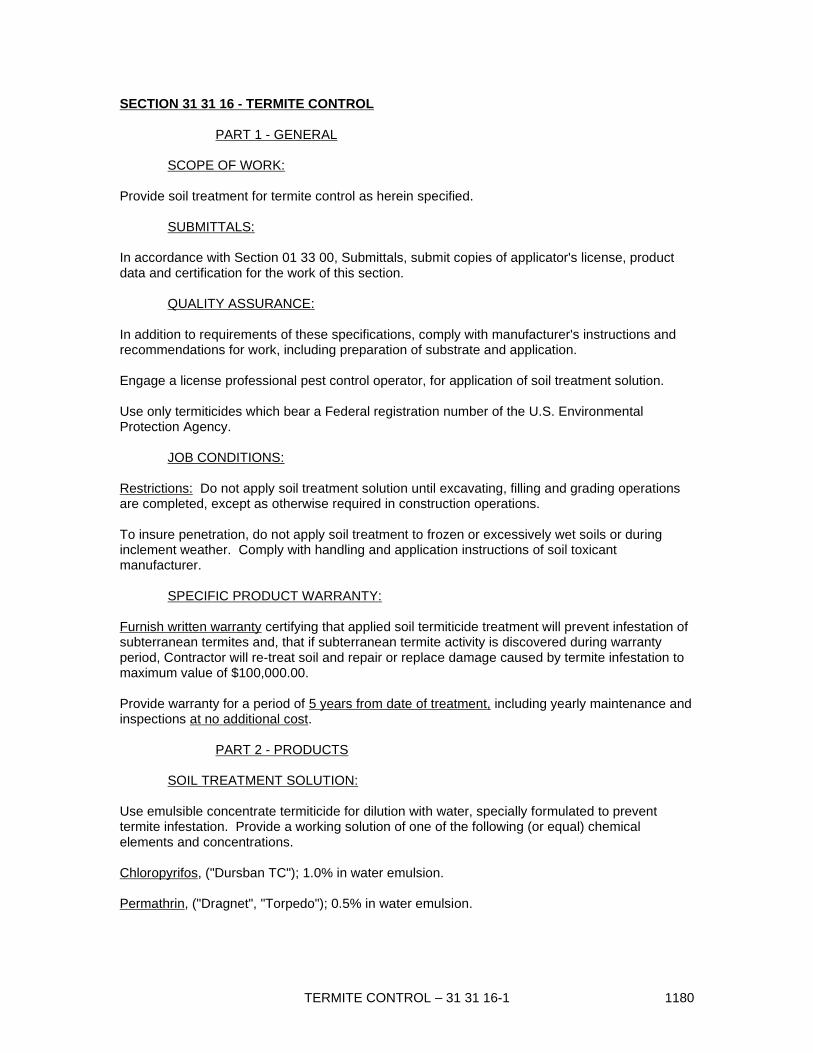
TERMITE CONTROL – 31 31 16-1 1180
SECTION 31 31 16 - TERMITE CONTROL
PART 1 - GENERAL
SCOPE OF WORK:
Provide soil treatment for termite control as herein specified.
SUBMITTALS:
In accordance with Section 01 33 00, Submittals, submit copies of applicator's license, product
data and certification for the work of this section.
QUALITY ASSURANCE:
In addition to requirements of these specifications, comply with manufacturer's instructions and
recommendations for work, including preparation of substrate and application.
Engage a license professional pest control operator, for application of soil treatment solution.
Use only termiticides which bear a Federal registration number of the U.S. Environmental
Protection Agency.
JOB CONDITIONS:
Restrictions: Do not apply soil treatment solution until excavating, filling and grading operations
are completed, except as otherwise required in construction operations.
To insure penetration, do not apply soil treatment to frozen or excessively wet soils or during
inclement weather. Comply with handling and application instructions of soil toxicant
manufacturer.
SPECIFIC PRODUCT WARRANTY:
Furnish written warranty certifying that applied soil termiticide treatment will prevent infestation of
subterranean termites and, that if subterranean termite activity is discovered during warranty
period, Contractor will re-treat soil and repair or replace damage caused by termite infestation to
maximum value of $100,000.00.
Provide warranty for a period of 5 years from date of treatment, including yearly maintenance and
inspections at no additional cost.
PART 2 - PRODUCTS
SOIL TREATMENT SOLUTION:
Use emulsible concentrate termiticide for dilution with water, specially formulated to prevent
termite infestation. Provide a working solution of one of the following (or equal) chemical
elements and concentrations.
Chloropyrifos, ("Dursban TC"); 1.0% in water emulsion.
Permathrin, ("Dragnet", "Torpedo"); 0.5% in water emulsion.

TERMITE CONTROL – 31 31 16-2 1180
Other solutions may be used as recommended by Applicator if acceptable by EPA and to local
governing authorities and to Architect. Use only soil treatment solutions which are not injurious to
planting.
PART 3 - EXECUTION
GENERAL:
Advise Owner's representative of schedule for application of solution. A minimum of 48 hours
notice will be required. Do not proceed without Owner's representative present to observe;
otherwise, a second application will be required.
APPLICATION:
Surface Preparation: Remove foreign matter which could decrease effectiveness of treatment on
areas to be treated. Loosen, rake, and level soil to be treated, except previously compacted
areas under slabs and foundations. Termiticide may be applied before placement of compacted
fill underslabs, if recommended by manufacturer.
Application Rates: Apply soil treatment solution as follows:
Under slab-on-grade, including all building structures, adjacent patios, walks and stoops, treat soil
before concrete slabs are placed using the following rates of application as a minimum:
Apply one gallon of chemical solution per 10 sq. ft. as an overall treatment under slab and
attached slab areas where fill is soil or unwashed gravel. Apply 1 1/2 gallons per 10 sq. ft. of
chemical solution to areas where fill is washed gravel or other coarse absorbent material.
Apply 4 gallons of chemical solution per 10 lin. ft. to soil critical areas under slabs, including entire
inside perimeter inside of foundation walls, along both sides of interior partition walls which
penetrate slab, around plumbing pipes and electric conduit penetrating slab, and around interior
column footers.
Apply 4 gallons of chemical solution per 10 lin. ft. of trench, for each foot of depth from grade to
footing, along outside edge of building. Mix chemical solution with the soil as it is being replaced
in trench.
At hollow masonry foundations or grade beams, treat voids at rate of 2 gal. per 10 lin. ft., poured
directly into the hollow spaces.
At expansion joints, control joints, and areas where slabs will be penetrated, apply at rate of 4
gals. per 10 lin. ft. of penetration.
Reapply soil treatment solution to areas disturbed by subsequent excavation, landscape grading,
or other construction activities following application.
END OF SECTION 31 31 16

CHAIN LINK FENCING AND GATES – 32 31 13-1 1121
SECTION 32 31 13 - CHAIN LINK FENCING AND GATES
PART 1 - GENERAL
DESCRIPTION OF WORK:
Extent of chain link fences and gates is indicated on drawings. Unless specified otherwise on the
drawings, the Fence Fabric shall be 8’0” in height.
QUALITY ASSURANCE:
Provide chain link fences and gates as complete units controlled by a single source including
necessary erection accessories, fittings, and fastenings.
SUBMITTALS:
In accordance with Section 01 33 00, Submittals, provide manufacturer's technical data, and
installation instructions for metal fencing, fabric, gates and accessories.
PART 2 - PRODUCTS
GENERAL:
Dimensions indicated for pipe, roll-formed, and H-sections are outside dimensions, exclusive of
coatings.
MANUFACTURERS:
Subject to compliance with requirements, manufacturers offering products which may be
incorporated in the work include, but are not limited to, the following:
Allied Tube and Conduit Corp.
American Fence Corp.
Anchor Fence, Inc.
STEEL FABRIC:
Furnish one-piece fabric widths for fencing up to 12" high.
Fabric Finish: Galvanized, ASTM A 392, Class II, with not less
than 2.0 oz. zinc per sq. ft. of surface. Fabric to be vinyl coated, shall have a 0.15 inch thick
black PVC coating in accordance with ASTM F668.
FRAMING AND ACCESSORIES:
Steel Framework, General: Galvanized steel, ASTM A 120 or A 123, with not less than 1.8 oz.
zinc per sq. ft. of surface.
Fittings and Accessories: Galvanized, ASTM A 153, with zinc weights per Table I.
End, Corner and Pull Posts: Minimum sizes and weights as follows:
Up to 6' fabric height, 2.375" OD steel pipe, 3.65 lbs. per lin. ft., 3.5" x 3.5" roll-formed sections, 4.85 lbs. per lin. ft.

CHAIN LINK FENCING AND GATES – 32 31 13-2 1121
Line Posts: Space 10' o.c. maximum, unless otherwise indicated, of following minimum sizes and
weights.
6' to 8' fabric height, 2.375" OD steel pipe, 3.65 lbs. per lin. ft. or 2.25" x 1.875" H-sections, 2.64
lbs. per lin. ft.
Gate Posts: Furnish posts for supporting single gate leaf, or one leaf of a double gate installation,
for nominal gate widths as follows:
Leaf Width Gate Post Lbs./lin. ft.
Up to 6' 3.5" x 3.5" roll-formed 4.85
section or 2.875" OD pipe 5.79
Top Rail: Manufacturer's longest lengths, with expansion type couplings, approximately 6" long,
for each joint. Provide means for attaching top rail securely to each gate corner, pull and end
post.
1.66" OD pipe, 2.27 lbs. per ft. or 1.625" x 1.25" roll-formed sections, 1.35 lbs. per ft.
Tension Wire: 7-gage, coated coil spring wire, metal and finish to match fabric.
Locate at bottom of fabric.
Wire Ties: galvanized steel or aluminum wire, to match fabric core material.
Post Brace Assembly: Manufacturer's standard adjustable brace at end and gate posts and at
both sides of corner and pull posts, with horizontal brace located at mid-height of fabric. Use
same materials as top rail for brace, and truss to line posts with 0.375" diameter rod and
adjustable tightener.
Post Tops: Provide weathertight closure cap with loop to receive tension wire or toprail; one cap
for each post.
Stretcher Bars: One-piece lengths equal to full height of fabric, with minimum cross-section of
3/16" x 3/4". Provide one stretcher bar for each gate and end post, and 2 for each corner and pull
post, except where fabric is integrally woven into post.
Stretcher Bars Bands: Space not over 15" o.c., to secure stretcher bars to end, corner, pull, and
gate posts.
GATES:
Fabrication: Fabricate perimeter frames of gates from metal and finish to match fence
framework. Assemble gate frames by welding or with special fittings and rivets, for rigid
connections, sections. Provide horizontal and vertical members to ensure proper gate operation
and attachment of fabric, hardware and accessories. Space frame members maximum of 8' apart
unless otherwise indicated.
Provide same fabric as for fence, unless otherwise indicated. Install fabric with stretcher bars at
vertical edges and at top and bottom edges. Attach stretchers bars to gate frame at not more
than 15" o.c.
Install diagonal cross-bracing consisting of 3/8" diameter adjustable length truss rods on gates to
ensure frame rigidity without sag or twist.
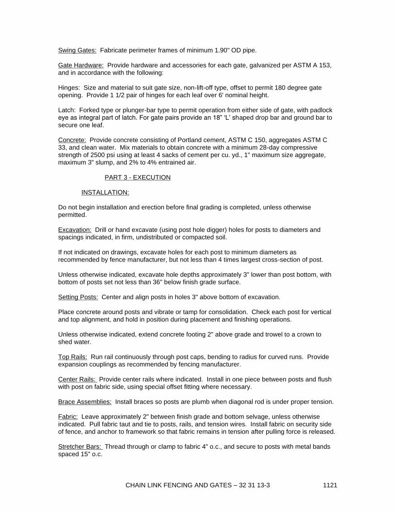
CHAIN LINK FENCING AND GATES – 32 31 13-3 1121
Swing Gates: Fabricate perimeter frames of minimum 1.90" OD pipe.
Gate Hardware: Provide hardware and accessories for each gate, galvanized per ASTM A 153,
and in accordance with the following:
Hinges: Size and material to suit gate size, non-lift-off type, offset to permit 180 degree gate
opening. Provide 1 1/2 pair of hinges for each leaf over 6' nominal height.
Latch: Forked type or plunger-bar type to permit operation from either side of gate, with padlock
eye as integral part of latch. For gate pairs provide an 18” ‘L’ shaped drop bar and ground bar to
secure one leaf.
Concrete: Provide concrete consisting of Portland cement, ASTM C 150, aggregates ASTM C
33, and clean water. Mix materials to obtain concrete with a minimum 28-day compressive
strength of 2500 psi using at least 4 sacks of cement per cu. yd., 1" maximum size aggregate,
maximum 3" slump, and 2% to 4% entrained air.
PART 3 - EXECUTION
INSTALLATION:
Do not begin installation and erection before final grading is completed, unless otherwise
permitted.
Excavation: Drill or hand excavate (using post hole digger) holes for posts to diameters and
spacings indicated, in firm, undistributed or compacted soil.
If not indicated on drawings, excavate holes for each post to minimum diameters as
recommended by fence manufacturer, but not less than 4 times largest cross-section of post.
Unless otherwise indicated, excavate hole depths approximately 3" lower than post bottom, with
bottom of posts set not less than 36" below finish grade surface.
Setting Posts: Center and align posts in holes 3" above bottom of excavation.
Place concrete around posts and vibrate or tamp for consolidation. Check each post for vertical
and top alignment, and hold in position during placement and finishing operations.
Unless otherwise indicated, extend concrete footing 2" above grade and trowel to a crown to
shed water.
Top Rails: Run rail continuously through post caps, bending to radius for curved runs. Provide
expansion couplings as recommended by fencing manufacturer.
Center Rails: Provide center rails where indicated. Install in one piece between posts and flush
with post on fabric side, using special offset fitting where necessary.
Brace Assemblies: Install braces so posts are plumb when diagonal rod is under proper tension.
Fabric: Leave approximately 2" between finish grade and bottom selvage, unless otherwise
indicated. Pull fabric taut and tie to posts, rails, and tension wires. Install fabric on security side
of fence, and anchor to framework so that fabric remains in tension after pulling force is released.
Stretcher Bars: Thread through or clamp to fabric 4" o.c., and secure to posts with metal bands
spaced 15" o.c.

CHAIN LINK FENCING AND GATES – 32 31 13-4 1121
Gates: Install gates plumb, level, and secure for full opening without interference . Install
ground-set items in concrete for anchorage. Adjust hardware for smooth operation and lubricate
where necessary.
Tie Wires: Use U-shaped wire, conforming to diameter of pipe to which attached, clasping pipe
and fabric firmly with ends twisted at least 2 full turns. Bend ends of wire to minimize hazard to
persons or clothing.
Tie fabric to line posts, with wore ties spaced 12" o.c. Tie fabric to rails and braces, with wore
ties spaced 24" o.c. Tie fabric to tension wires, with hog rings spaced 24" o.c.
Fasteners: Install nuts for tension bands and hardware bolts on side of fence opposite fabric
side. Peen ends of bolts or score threads to prevent removal of nuts.
END OF SECTION 32 31 13