Blower Cabinets - US Air Conditioning Distributorspartscounter.us-ac.com/Reznor/Reznor Literature...
16
Mfg #163219, Page 1 APPLIES TO: Models RBL, RBA, RBHA Blower Cabinets INSTALLATION FORM RGM 409 WARNING: Improper installation, adjustment, alteration, service, or maintenance can cause property damage, injury or death. Read the installation, operation, and maintenance instructions thoroughly before installing or servicing this equipment. GENERAL Installation should be done by a qualified agency in accordance with the instructions in this manual and in compliance with all codes and requirements of authorities having jurisdiction. The instructions in this manual apply to the following models of Reznor ® blower cabinets. Model Standard Characteristics RBA Indoor/outdoor, 1500-5000 CFM Range RBHA Indoor/outdoor, 1500-5000 CM, specially designed to accommodate circulating air temperatures up to 300 o F RBL Indoor/Outdoor, 5000-15000 CFM Range These blower cabinets are engineered for use with Reznor ® duct furnaces when design considerations do not permit the use of a packaged system. The cabinets are weatherized with an integral curb cap base for outdoor installation, but may also be installed indoors. All blower cabinets have standard horizontal inlet and outlet air openings equipped with duct flanges. All models are available with an optional bottom air inlet. Model RBL is avail- able with a downturn plenum which provides a bottom outlet for supply air. Model RBL and RBA are available with other vari- ous option selections. Model RBHA is designed specially for applications that require circulating air temperatures up to 300 o F. The blower motor bearings and adjustable drive in a Model RBHA are mounted in a weatherized housing external to the airstream. Before beginning installation, review the instructions in this booklet and become familiar with the particular style of blower cabinet being installed. 1. Uncrating Immediately upon uncrating the unit, check for any damage that may have been incurred during shipment. If damage is found, file a claim with the transporting agency. This unit was inspected at the factory immediately prior to crating. Check the blower cabinet plate to be sure that the electrical char- acteristics of the blower cabinet are compatible with the instal- lation site. Be sure all shipped-separate options for the installation are avail- able. Check to see if there are field installed options that need to be assembled prior to installation. Field-installed options could include a roof curb, an outside air hood, an evaporative cooling module, a cooling module fill and drain kit, and/or a disconnect switch. The "Owner's Envelope" shipped inside the blower cabinet in- cludes instructions and warranty information. HAZARD INTENSITY LEVELS 1. DANGER: Failure to comply will result in severe personal injury or death and/or property damage. 2. WARNING: Failure to comply could result in se- vere personal injury or death and/or property dam- age. 3. CAUTION: Failure to comply could result in mi- nor personal injury and/or property damage. Page Adjusting Blower Speed ......................... 7 Optional Air Flow Proving Switch ........ 8 Belts ....................................................... 7 Blower Rotation ..................................... 7 Blowers ................................................... 7 Check/Test/Start-up ................................ 9 Dampers and Controls (Optional) ........ 11 Dimensions ............................................. 2 Disconnect Switch .................................. 6 Page Drives .................................................... 7 Duct Connections ................................... 5 Electrical Supply and Connections ........ 6 Evaporative Cooling Module (Optional) ..................... 12 Filter Arrangements ................................ 8 Filters (Optional) .................................... 8 General ................................................... 1 Hazard Intensity Levels .......................... 1 Table of Contents Installation/Operation .... Paragraphs 1-8 ................. Pages 1-9 Check/Test/Start ............. Paragraph 9 .......................... Page 9 Optional Accessories ...... Paragraphs 10-13 ......... Pages 10-16 Page Motors .................................................... 8 Mounting ................................................ 3 100% Outside Air Hood (Optional) ... 10 30% Outside Air Hood (Optional) ...... 11 Roof Curb .............................................. 4 Suspending ............................................. 3 Uncrating ............................................... 1 Control Wiring ........................................ 6
Transcript of Blower Cabinets - US Air Conditioning Distributorspartscounter.us-ac.com/Reznor/Reznor Literature...
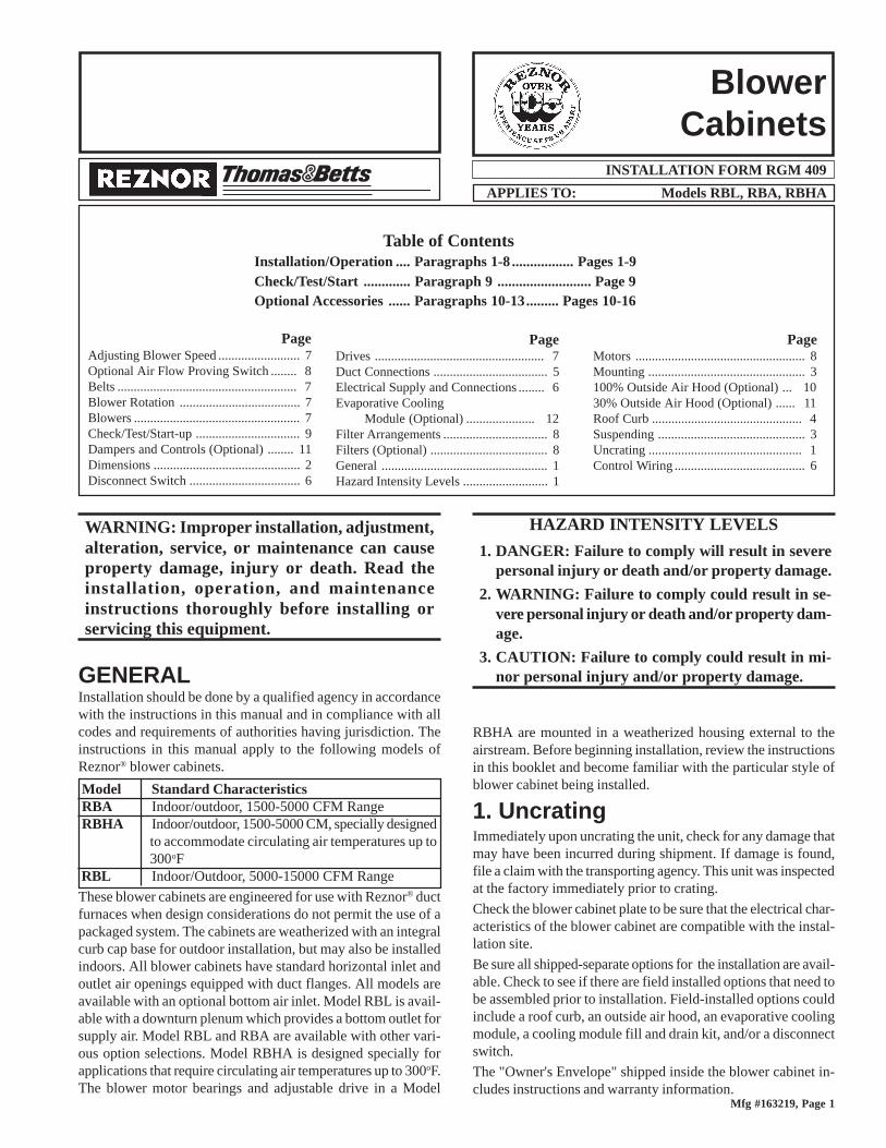
Mfg #163219, Page 1
APPLIES TO: Models RBL, RBA, RBHA
BlowerCabinets
INSTALLATION FORM RGM 409
WARNING: Improper installation, adjustment,alteration, service, or maintenance can causeproperty damage, injury or death. Read theinstallation, operation, and maintenanceinstructions thoroughly before installing orservicing this equipment.
GENERALInstallation should be done by a qualified agency in accordancewith the instructions in this manual and in compliance with allcodes and requirements of authorities having jurisdiction. Theinstructions in this manual apply to the following models ofReznor® blower cabinets.
Model Standard CharacteristicsRBA Indoor/outdoor, 1500-5000 CFM RangeRBHA Indoor/outdoor, 1500-5000 CM, specially designed
to accommodate circulating air temperatures up to300oF
RBL Indoor/Outdoor, 5000-15000 CFM Range
These blower cabinets are engineered for use with Reznor® ductfurnaces when design considerations do not permit the use of apackaged system. The cabinets are weatherized with an integralcurb cap base for outdoor installation, but may also be installedindoors. All blower cabinets have standard horizontal inlet andoutlet air openings equipped with duct flanges. All models areavailable with an optional bottom air inlet. Model RBL is avail-able with a downturn plenum which provides a bottom outlet forsupply air. Model RBL and RBA are available with other vari-ous option selections. Model RBHA is designed specially forapplications that require circulating air temperatures up to 300oF.The blower motor bearings and adjustable drive in a Model
RBHA are mounted in a weatherized housing external to theairstream. Before beginning installation, review the instructionsin this booklet and become familiar with the particular style ofblower cabinet being installed.
1. UncratingImmediately upon uncrating the unit, check for any damage thatmay have been incurred during shipment. If damage is found,file a claim with the transporting agency. This unit was inspectedat the factory immediately prior to crating.
Check the blower cabinet plate to be sure that the electrical char-acteristics of the blower cabinet are compatible with the instal-lation site.
Be sure all shipped-separate options for the installation are avail-able. Check to see if there are field installed options that need tobe assembled prior to installation. Field-installed options couldinclude a roof curb, an outside air hood, an evaporative coolingmodule, a cooling module fill and drain kit, and/or a disconnectswitch.
The "Owner's Envelope" shipped inside the blower cabinet in-cludes instructions and warranty information.
HAZARD INTENSITY LEVELS
1. DANGER: Failure to comply will result in severepersonal injury or death and/or property damage.
2. WARNING: Failure to comply could result in se-vere personal injury or death and/or property dam-age.
3. CAUTION: Failure to comply could result in mi-nor personal injury and/or property damage.
PageAdjusting Blower Speed ......................... 7Optional Air Flow Proving Switch ........ 8Belts ....................................................... 7Blower Rotation ..................................... 7Blowers ................................................... 7Check/Test/Start-up ................................ 9Dampers and Controls (Optional) ........ 11Dimensions ............................................. 2Disconnect Switch .................................. 6
PageDrives .................................................... 7Duct Connections ................................... 5Electrical Supply and Connections ........ 6Evaporative Cooling
Module (Optional) ..................... 12Filter Arrangements ................................ 8Filters (Optional) .................................... 8General ................................................... 1Hazard Intensity Levels .......................... 1
Table of ContentsInstallation/Operation .... Paragraphs 1-8 ................. Pages 1-9Check/Test/Start ............. Paragraph 9 .......................... Page 9Optional Accessories ...... Paragraphs 10-13......... Pages 10-16
PageMotors .................................................... 8Mounting ................................................ 3100% Outside Air Hood (Optional) ... 1030% Outside Air Hood (Optional) ...... 11Roof Curb .............................................. 4Suspending ............................................. 3Uncrating ............................................... 1Control Wiring ........................................ 6

Form 409, Page 2
2. Dimensions
Model RBL Air Openings (with duct flange) Dimensions (inches)Standard Horizontal Inlet Air Opening 19-1/2 x 47-5/8
Optional Return Air Inlet (Bottom) Air Opening 19-1/2 x 47-5/8Standard Horizontal Discharge Air Opening 22-1/8 x 48-15/16
Optional Discharge Air Opening with Downturn 19-1/2 x 47-5/8
Figure 1B - Model RBL with Optional Downturn Plenum Cabinet
Figure 1A - Model RBL (Indoor/Outdoor, 5000 - 15000 CFM Range)

Mfg #163219, Page 3
Model RBA and RBHAAir Openings (with duct flange) Dimensions (inches)Standard Horizontal Inlet Air Opening 19-1/2 x 22-7/8
Optional Return Air Inlet (Bottom) Air Opening 19-1/2 x 22-7/8
Standard Horizontal Discharge Air Opening 18 x 28-3/4
Figure 2 - Model RBA (Indoor/Outdoor, 1500-5000 CFM Range)
Figure 3 - Model RBHA (Indoor/Outdoor, 1500-5000 CFM Range, speciallydesigned to accommodate circulating air temperatures up to 300oF)
3. Suspending/MountingBefore installing the blower cabinet, check the supporting struc-ture to verify that it has sufficient load-carrying capacity to sup-port the weight.
Model New Weight (lbs)
RBA 212
RBHA 265
RBL 488
Depending on the building structure and its use, determinewhether or not measures should be taken to reduce the effect ofblower vibration and/or noise. Determining the need for andinstalling vibration isolation is the responsibility of the installer.
Suspending Indoor Cabinets
Blower cabinets maybe suspended usingfield-furnished rodhangers. Insert 1/2"rods into the holes atthe corners of the curbcap. Attach rods tothe unit as illustratedin Figure 4.
Figure 4 - Support Rod Detail

Form 409, Page 4
3. Suspending/Mounting (cont'd)Suspending Indoor Cabinets (cont'd)Attach rods to the building structure. See Figure 5. Propersuspension of this cabinet is the responsibility of the in-staller.
Mounting Outdoor CabinetsBlower cabinets are equipped with a load bearing curbcap which forms an integral part of the unit. This curbcap is welded at all joints and has a "skirt" which fitsover a roof curb to provide a weatherproof installation.Use the lifting lugs provided.
The blower cabinet may be mounted on an optional roofcurb, a field-supplied roof curb, or field supplied sup-ports. If the system has a downturn plenum and/or a bot-tom return air opening, a roof curb is recommended toprovide a weatherproof installation as well as more work-able clearances for ductwork. The blower cabinet curbcap is not designed to be placed directly on the roof sur-face. When positioning rooftop equipment, it is recom-mended that the air inlet does not face into the prevail-ing wind.
Mounting on Field Supplied Supports (without a roofcurb) - Prior to installation, be sure that the method ofsupport is in agreement with all local building codes andis suited to the climate. If considering this type of instal-lation in snow areas, it is recommended that the 4x4wooden rails underneath the unit be on cross-supportstructure at least 12" higher than the roof surface. Whetherthe supports are being mounted directly on the roof orbeing placed "up" on additional structure, the horizontallength of the unit should be supported by two 4x4 treatedwooden rails. Cut the rails to the appropriate length (Di-mension "A") in Figure 6. (NOTE: Although dimensionsare included for units with a downturn plenum cabinet, itis strongly recommended that roof curb be used on aninstallation with a downturn plenum cabinet and/or a bot-tom return air duct.) Space the 4x4 wooden support rails(See "B" Dimension in Figure 6) so that the curb cap"skirt" will fit over the edge of the boards with the railsetting inside the horizontal length of the curb cap.
If the rails are being laid directly on the roof, positionthem as shown in Figure 6. Set the unit on the rails.NOTE: It is recommended that there be a minimum of14" between the bottom of the inlet air hood (see Para-graph 11) and the mounting surface.
If the treated wooden rails are not placed directly on the roof surface,cross supports should be placed underneath the rails at the ends of thecabinet. The filed-supplied, weather-resistant cross-support structuremust be adequate for the weight of the unit and run the entire width ofthe cabinet supporting the 4x4 wooden rails.Mounting on a Roof Curb - Whether using an optional roof curb avail-able for the cabinet or a field-supplied curb, the curb must be squareand level and a minimum height of 14" The top surface of the roof curbmust be caulked with 1/4 x 1-1/4 sealant tape or 1/4" beads of suitablesealant. The cabinet must be sealed to the curb to prevent water leakageinto the curb area due to windblown rain and capillary action. Exceptfor the curb assembly details, the information and requirements in thissection apply to both an optional curb and a field-supplied curb. SeeFigure 8 and curb installation instructions.
Bottom Duct Connections - Both the optional return air opening andthe opening in the downturn plenum have duct flanges. Duct openingsizes and spacing in relation to an optional roof curb are shown in Fig-ure 7.
Reznor® Optional Roof Curb Installation Instructions (See Figure 8)
Curbs are shipped unassembled. Field assembly and mounting on theroof are the responsibility of the installer. Hardware to assemble thecorners is supplied, Before installing the roof curb, verify that the sizeis correct for the cabinet being installed.
Figure 5 - Blower CabinetSuspended by Rod Hangers
Models Standard Model RBL Model RBL withRBA, RBHA Blower Cabinet Downturn Plenum CabinetA B A B A B
37-1/16 28-13/16 59-1/16 53-9/16 82-1/16 53-9/16
Figure 6 - Support Rail Dimensions
Dimensions A BStandard RBL Cabinet NA 47-5/8"RBL with Downturn Plenum 55-13/16" 47-5/8"RBA and RBHA Cabinet N/A 22-7/8"
Figure 7 - Roof Curb and Optional Duct Opening Dimensions
Return and Supply Duct Dimensions and Locations inRelation to Reznor® Optional Roof Curb
1-5/8" is measurement from duct opening to inside edge of roof curb.
NOTE: Cut duct openings 1" larger than the duct size for installationclearance.

Mfg #163219, Page 5
1. Position the curb cross rails and curb side rails as shown inFigure 8. Fasten curbing pieces at all corners with bolts andlag screws as shown in the Corner Detail illustration.
2. Check the assembly for squareness. Adjust the roof open-ing so that the diagonal measurements are equal within atolerance of ± 1/8".
3. Level the roof curb. To ensure a good weathertight seal be-tween the integral curb cap and the roof curb, the roof curbmust be leveled in both directions with no twist end to end.
4. Duct ConnectionsNOTES: For systems with a downturn cabinet, the type of ductinstallation to be used depends in part on the type of construc-tion of the roof (whether wood joist, steel bar joist, steel truss,precast concrete) and the ceiling (whether hung, flush, etc.).
For cabinets without a downturn, a minimum horizontal ductrun of 24 inches is recommended before turns or branches aremade in the duct system, to reduce losses at the furnace outlet.
Make certain return air ducting and grills have a free area equalto the return duct size connection. See Paragraph 2 for ductopening dimensions.
Suggestions for Installing DuctsA. The type of duct installation to be used depends in part on
the type of construction of the roof (whether wood joist,steel bar joist, steel truss, precast concrete) and the ceiling(whether hung, flush, etc.). Duct connections should bemechanical.
B. Rectangular duct should be constructed of not lighter than No.26 U.S. gauge galvanized iron or No. 24 B & S gauge alumi-num.
C. All duct sections 24 inches or wider, and over 48 inches inlength, should be cross broken on top and bottom and shouldhave standing seams or angle-iron braces. Joints should be Sand drive strip, or locked.
D. No warm air duct should come in contact with masonry walls.Insulate around all air ducts through masonry walls with notless than 1/2 inch of insulation.
E. Insulate all exposed warm air ducts passing through an un-heated space with at least 1/2 inch thickness of insulation.
F. For optional bottom openings, insert ducts from below roofdeck through roof opening into cabinet. Form 1" flanges, foldover, and fasten with sheet metal screws. Gain access by re-moving side panels from blower and downturn plenum sec-tions.
Shim level as required and secure curb to roof deck beforeproceeding with flashing.
4. Install field-supplied flashing (See Figure 8).5. Before placing the unit on the curb, apply furnished
1/4 x 1-1/4" foam sealant tape to the top surface of the curb,making good butt joint at the corners. The cabinet must besealed to the curb to prevent water leakage into the curb areadue to blown rain and capillary action.
Dimensions Model RBL Model RBA/RBHAStandard (without With Optional Downturn Plenum RoofDownturn) - Roof Cabinet (Option AQ5 or AQ8) CurbCurb Option CJ1 - Roof Curb Option CJ2 Option CJ1
A 59-1/16 82-1/16 37-1/16B 53-9/16 53-9/16 28-13/16
C* 55-5/16 78-5/16 33-5/16D* 49-13/16 49-13/16 25-1/16
* C and D are roof open-ing dimensions.
Figure 8 -Roof CurbInstallation
IMPORTANT: Top surface of thecurb MUST be sealed. See Roof CurbAssembly an Installatin Instructions.

Form 409, Page 6
G. Duct Supports -- Suspend all ducts securely from adjacentbuildings members. Do not support ducts from unit duct con-nections.
H. Duct Sizing -- Proper sizing of the warm air ductwork is nec-essary to ensure a satisfactory heating installation. The rec-ognized authority for such information is the Air Condition-ing Contractors Association, 1228 17th Street N.W., Wash-ington, D.C. 20036. A manual covering duct sizing in detailmay be purchased directly from them.
CAUTION: An external duct system staticpressure not within the limits shown on the ratingplate, or improper motor pulley or beltadjustment, may overload the motor. See HazardLevels, page 1.
4. Duct Connections (cont'd)
All electrical wiring and connections, including electrical ground-ing MUST be made in accordance with the National ElectricCode ANSI/NFPA No. 70 (latest edition) or, in Canada, theCanadian Electrical Code, Part I-C.S.A. Standard C22.1. In ad-dition, the installer should be aware of any local ordinances orgas company requirements that might apply.
Check the plate on the cabinet for the supply voltage and currentrequirements. A separate line voltage supply with fused discon-nect switch should be run directly from the main electrical panel,making connection to leads in the junction box. All external wir-ing must be within approved conduit and have a minimum tem-perature rise of 60oC. Conduit from the disconnect switch mustbe run so as not to interfere with the service panels of the cabi-net. The unit must be electrically grounded in accordance withthe national Electrical Code, ANSI/NFPA No. 70 (latest editionor CSA Standard C22.1 when installed, if an external electricalsource is used.
5. Electrical Supply and Connections
CAUTION: If any of the original wire assupplied with the appliance must be replaced, itmust be replaced with wiring material having atemperature rating of at least 105oC. See HazardLevels, page 1.
If the installation includes field-installed options that require elec-trical connections, consult the instruction sheet and wiring dia-gram supplied in the option package. Optional shipped-separatecontrols could include system switches, potentiometer, a pres-sure null switch, or a combination of these controls. Install theseaccording to the manufacturer's instructions packed with thecabinet.
Check the wiring diagram and literature supplied with the cabi-net for operation of factory-installed optional controls. See Fig-ure 9 for location of electrical connections and available stan-dard and optional controls.
Disconnect SwitchA disconnect switch is a required part of this installation. Switchesare available, as options or parts, or may be purchased locally.When ordered as an optional component, the disconnect switchis shipped separately.The disconnect switch may be fusible or non-fusible. When in-stalling, be careful that the conduit and switch housing are clearof cabinet panels. Allow at least four feet of service room be-tween the switch and removable panels.
Control WiringTotal Distance from unit Minimum Recommended
Wire Length to Control Wire Size
150 ft 75 ft #18 gauge
250 ft 125 ft #16 gauge
350 ft 175 ft #14 gauge
Figure 9 - Location of Electrical Connections andStandard and Optional Controls (Illustration shows aModel RBA; controls are in same location in RBL cabinet.)
1. Line Voltage Connection (field)2. Optional Convenience Outlet and Convenience Outlet Transformer3. Blower Motor Contactor or Starter4. Optional Outside Air or Return Air Controller5. Optional Mixed Air Controller6. Optional Potentiometer7. Optional Potentiometer8. Optional Return Air Dampers9. Optional Filters10.Optional Two-Position or Modulating Damper Motor11.Optional Outside Air Dampers12.Blower Motor (Drive on opposite Side) - Available in Open, TEFC,
Energy Efficient or Two-Speed13.Optional Control Relays (as required - 8 maximum)14.Low Voltage Terminal Strip15.Line Voltage Terminal Strip16.Control Transformer17.Control Transformer (as required)18.Optional Damper Motor Transformer19.Low Voltage Connection (field)
Mfg #163219, Page 7
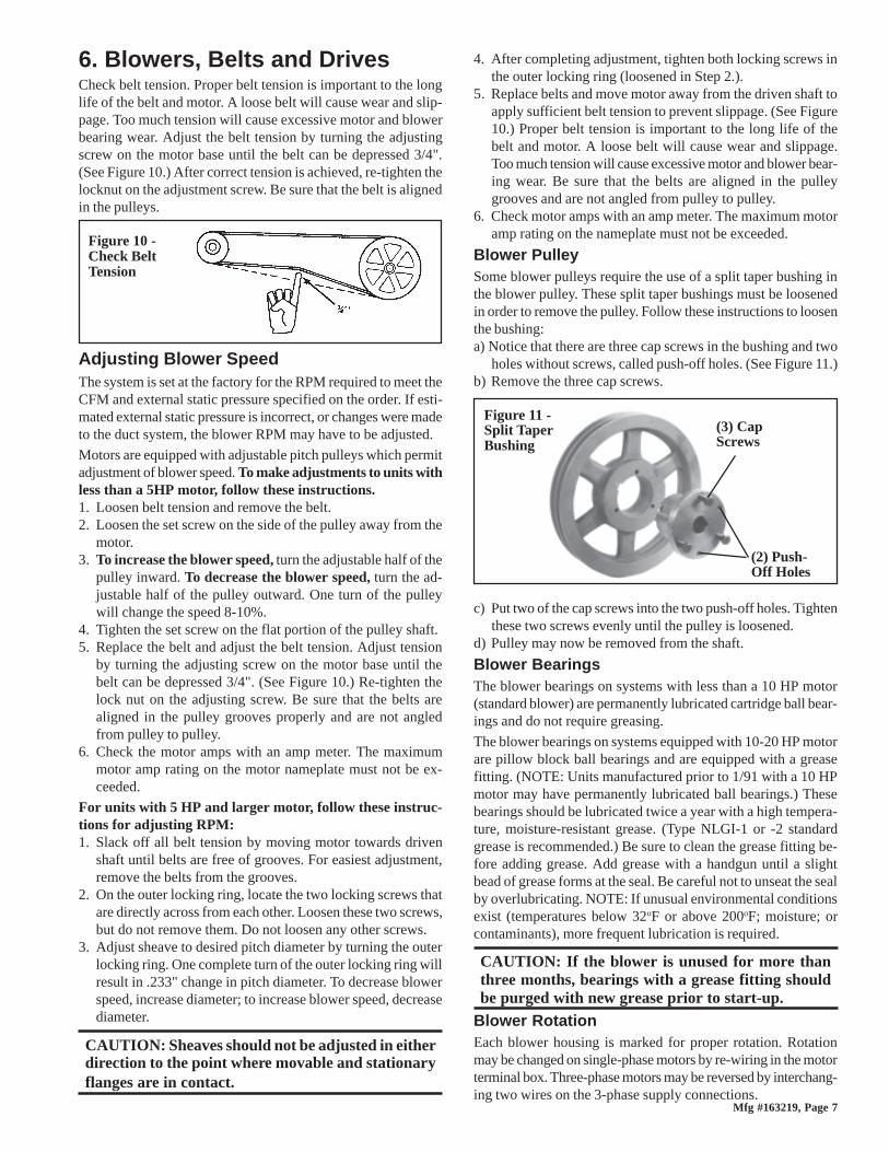
6. Blowers, Belts and DrivesCheck belt tension. Proper belt tension is important to the longlife of the belt and motor. A loose belt will cause wear and slip-page. Too much tension will cause excessive motor and blowerbearing wear. Adjust the belt tension by turning the adjustingscrew on the motor base until the belt can be depressed 3/4".(See Figure 10.) After correct tension is achieved, re-tighten thelocknut on the adjustment screw. Be sure that the belt is alignedin the pulleys.
Adjusting Blower SpeedThe system is set at the factory for the RPM required to meet theCFM and external static pressure specified on the order. If esti-mated external static pressure is incorrect, or changes were madeto the duct system, the blower RPM may have to be adjusted.
Motors are equipped with adjustable pitch pulleys which permitadjustment of blower speed. To make adjustments to units withless than a 5HP motor, follow these instructions.1. Loosen belt tension and remove the belt.2. Loosen the set screw on the side of the pulley away from the
motor.3. To increase the blower speed, turn the adjustable half of the
pulley inward. To decrease the blower speed, turn the ad-justable half of the pulley outward. One turn of the pulleywill change the speed 8-10%.
4. Tighten the set screw on the flat portion of the pulley shaft.5. Replace the belt and adjust the belt tension. Adjust tension
by turning the adjusting screw on the motor base until thebelt can be depressed 3/4". (See Figure 10.) Re-tighten thelock nut on the adjusting screw. Be sure that the belts arealigned in the pulley grooves properly and are not angledfrom pulley to pulley.
6. Check the motor amps with an amp meter. The maximummotor amp rating on the motor nameplate must not be ex-ceeded.
For units with 5 HP and larger motor, follow these instruc-tions for adjusting RPM:1. Slack off all belt tension by moving motor towards driven
shaft until belts are free of grooves. For easiest adjustment,remove the belts from the grooves.
2. On the outer locking ring, locate the two locking screws thatare directly across from each other. Loosen these two screws,but do not remove them. Do not loosen any other screws.
3. Adjust sheave to desired pitch diameter by turning the outerlocking ring. One complete turn of the outer locking ring willresult in .233" change in pitch diameter. To decrease blowerspeed, increase diameter; to increase blower speed, decreasediameter.
CAUTION: Sheaves should not be adjusted in eitherdirection to the point where movable and stationaryflanges are in contact.
Figure 10 -Check BeltTension
4. After completing adjustment, tighten both locking screws inthe outer locking ring (loosened in Step 2.).
5. Replace belts and move motor away from the driven shaft toapply sufficient belt tension to prevent slippage. (See Figure10.) Proper belt tension is important to the long life of thebelt and motor. A loose belt will cause wear and slippage.Too much tension will cause excessive motor and blower bear-ing wear. Be sure that the belts are aligned in the pulleygrooves and are not angled from pulley to pulley.
6. Check motor amps with an amp meter. The maximum motoramp rating on the nameplate must not be exceeded.
Blower PulleySome blower pulleys require the use of a split taper bushing inthe blower pulley. These split taper bushings must be loosenedin order to remove the pulley. Follow these instructions to loosenthe bushing:a) Notice that there are three cap screws in the bushing and two
holes without screws, called push-off holes. (See Figure 11.)b) Remove the three cap screws.
c) Put two of the cap screws into the two push-off holes. Tightenthese two screws evenly until the pulley is loosened.
d) Pulley may now be removed from the shaft.
Blower BearingsThe blower bearings on systems with less than a 10 HP motor(standard blower) are permanently lubricated cartridge ball bear-ings and do not require greasing.
The blower bearings on systems equipped with 10-20 HP motorare pillow block ball bearings and are equipped with a greasefitting. (NOTE: Units manufactured prior to 1/91 with a 10 HPmotor may have permanently lubricated ball bearings.) Thesebearings should be lubricated twice a year with a high tempera-ture, moisture-resistant grease. (Type NLGI-1 or -2 standardgrease is recommended.) Be sure to clean the grease fitting be-fore adding grease. Add grease with a handgun until a slightbead of grease forms at the seal. Be careful not to unseat the sealby overlubricating. NOTE: If unusual environmental conditionsexist (temperatures below 32oF or above 200oF; moisture; orcontaminants), more frequent lubrication is required.
CAUTION: If the blower is unused for more thanthree months, bearings with a grease fitting shouldbe purged with new grease prior to start-up.
Blower RotationEach blower housing is marked for proper rotation. Rotationmay be changed on single-phase motors by re-wiring in the motorterminal box. Three-phase motors may be reversed by interchang-ing two wires on the 3-phase supply connections.
(3) CapScrews
Figure 11 -Split TaperBushing
(2) Push-Off Holes
Form 409, Page 8
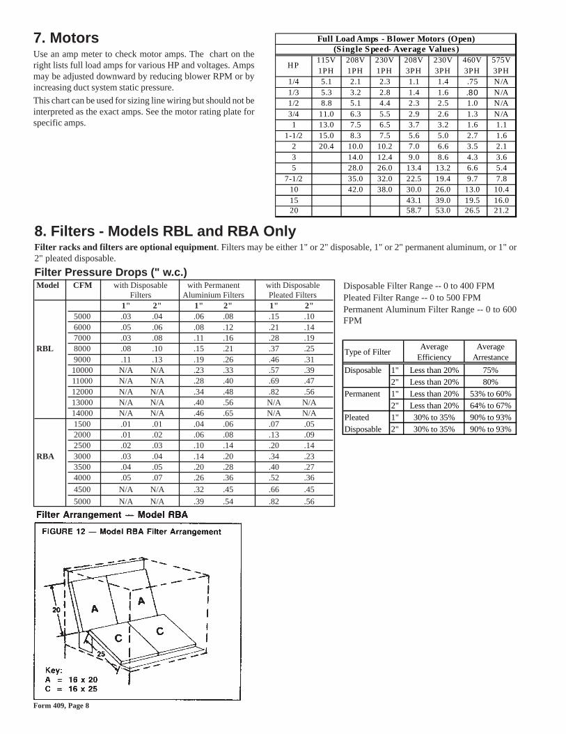
7. MotorsUse an amp meter to check motor amps. The chart on theright lists full load amps for various HP and voltages. Ampsmay be adjusted downward by reducing blower RPM or byincreasing duct system static pressure.
This chart can be used for sizing line wiring but should not beinterpreted as the exact amps. See the motor rating plate forspecific amps.
8. Filters - Models RBL and RBA OnlyFilter racks and filters are optional equipment. Filters may be either 1" or 2" disposable, 1" or 2" permanent aluminum, or 1" or2" pleated disposable.
Filter Pressure Drops (" w.c.)Model CFM with Disposable with Permanent with Disposable
Filters Aluminium Filters Pleated Filters1" 2" 1" 2" 1" 2"
5000 .03 .04 .06 .08 .15 .106000 .05 .06 .08 .12 .21 .147000 .03 .08 .11 .16 .28 .19
RBL 8000 .08 .10 .15 .21 .37 .259000 .11 .13 .19 .26 .46 .3110000 N/A N/A .23 .33 .57 .3911000 N/A N/A .28 .40 .69 .4712000 N/A N/A .34 .48 .82 .5613000 N/A N/A .40 .56 N/A N/A14000 N/A N/A .46 .65 N/A N/A1500 .01 .01 .04 .06 .07 .052000 .01 .02 .06 .08 .13 .092500 .02 .03 .10 .14 .20 .14
RBA 3000 .03 .04 .14 .20 .34 .233500 .04 .05 .20 .28 .40 .274000 .05 .07 .26 .36 .52 .36
4500 N/A N/A .32 .45 .66 .45
5000 N/A N/A .39 .54 .82 .56
Full Load Amps - Blower Motors (Open)(Single Speed- Average Values )
HP115V 1PH
208V 1PH
230V 1PH
208V 3PH
230V 3PH
460V 3PH
575V 3PH
1/4 5.1 2.1 2.3 1.1 1.4 .75 N/A1/3 5.3 3.2 2.8 1.4 1.6 .80 N/A1/2 8.8 5.1 4.4 2.3 2.5 1.0 N/A3/4 11.0 6.3 5.5 2.9 2.6 1.3 N/A1 13.0 7.5 6.5 3.7 3.2 1.6 1.1
1-1/2 15.0 8.3 7.5 5.6 5.0 2.7 1.62 20.4 10.0 10.2 7.0 6.6 3.5 2.13 14.0 12.4 9.0 8.6 4.3 3.65 28.0 26.0 13.4 13.2 6.6 5.4
7-1/2 35.0 32.0 22.5 19.4 9.7 7.810 42.0 38.0 30.0 26.0 13.0 10.415 43.1 39.0 19.5 16.020 58.7 53.0 26.5 21.2
Type of FilterAverage
EfficiencyAverage
Arrestance
Disposable 1" Less than 20% 75%2" Less than 20% 80%
Permanent 1" Less than 20% 53% to 60%2" Less than 20% 64% to 67%
Pleated 1" 30% to 35% 90% to 93%Disposable 2" 30% to 35% 90% to 93%
Disposable Filter Range -- 0 to 400 FPMPleated Filter Range -- 0 to 500 FPMPermanent Aluminum Filter Range -- 0 to 600FPM

Mfg #163219, Page 9
9. Check/Test/Start-Up - All ModelsBe certain electrical supply matches voltage rating on unit (see rating plate).
�Check all field wiring against wiring diagram. Be sure wire gauges are as required for the electrical load. This information appearson the wiring diagram.
�Be certain that electrical entries are sealed against the weather.
�See that fuses or circuit breakers are in place and sized correctly.
�Check blower pulley and motor pulley to be sure they are secure to shafts. Check belt tension; see Paragraph 6.
� If the unit is equipped with outside air and return air dampers, adjust the damper linkage. See Paragraph 12.
�Close all panels tightly.
�Return this book to the "Owner's Envelope" for future reference.
Form 409, Page 10
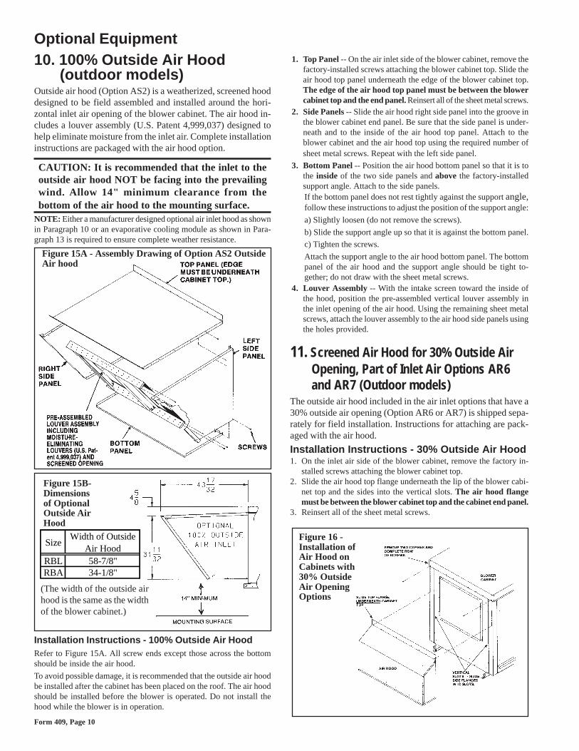
Optional Equipment10. 100% Outside Air Hood
(outdoor models)Outside air hood (Option AS2) is a weatherized, screened hooddesigned to be field assembled and installed around the hori-zontal inlet air opening of the blower cabinet. The air hood in-cludes a louver assembly (U.S. Patent 4,999,037) designed tohelp eliminate moisture from the inlet air. Complete installationinstructions are packaged with the air hood option.
CAUTION: It is recommended that the inlet to theoutside air hood NOT be facing into the prevailingwind. Allow 14" minimum clearance from thebottom of the air hood to the mounting surface.
NOTE: Either a manufacturer designed optional air inlet hood as shownin Paragraph 10 or an evaporative cooling module as shown in Para-graph 13 is required to ensure complete weather resistance.
Installation Instructions - 100% Outside Air HoodRefer to Figure 15A. All screw ends except those across the bottomshould be inside the air hood.
To avoid possible damage, it is recommended that the outside air hoodbe installed after the cabinet has been placed on the roof. The air hoodshould be installed before the blower is operated. Do not install thehood while the blower is in operation.
Figure 15A - Assembly Drawing of Option AS2 OutsideAir hood
Figure 15B-Dimensionsof OptionalOutside AirHood
(The width of the outside airhood is the same as the widthof the blower cabinet.)
11. Screened Air Hood for 30% Outside AirOpening, Part of Inlet Air Options AR6and AR7 (Outdoor models)
The outside air hood included in the air inlet options that have a30% outside air opening (Option AR6 or AR7) is shipped sepa-rately for field installation. Instructions for attaching are pack-aged with the air hood.
Installation Instructions - 30% Outside Air Hood1. On the inlet air side of the blower cabinet, remove the factory in-
stalled screws attaching the blower cabinet top.2. Slide the air hood top flange underneath the lip of the blower cabi-
net top and the sides into the vertical slots. The air hood flangemust be between the blower cabinet top and the cabinet end panel.
3. Reinsert all of the sheet metal screws.
Figure 16 -Installation ofAir Hood onCabinets with30% OutsideAir OpeningOptions
SizeWidth of Outside
Air HoodRBL 58-7/8"RBA 34-1/8"
1. Top Panel -- On the air inlet side of the blower cabinet, remove thefactory-installed screws attaching the blower cabinet top. Slide theair hood top panel underneath the edge of the blower cabinet top.The edge of the air hood top panel must be between the blowercabinet top and the end panel. Reinsert all of the sheet metal screws.
2. Side Panels -- Slide the air hood right side panel into the groove inthe blower cabinet end panel. Be sure that the side panel is under-neath and to the inside of the air hood top panel. Attach to theblower cabinet and the air hood top using the required number ofsheet metal screws. Repeat with the left side panel.
3. Bottom Panel -- Position the air hood bottom panel so that it is tothe inside of the two side panels and above the factory-installedsupport angle. Attach to the side panels.If the bottom panel does not rest tightly against the support angle,follow these instructions to adjust the position of the support angle:
a) Slightly loosen (do not remove the screws).
b) Slide the support angle up so that it is against the bottom panel.
c) Tighten the screws.
Attach the support angle to the air hood bottom panel. The bottompanel of the air hood and the support angle should be tight to-gether; do not draw with the sheet metal screws.
4. Louver Assembly -- With the intake screen toward the inside ofthe hood, position the pre-assembled vertical louver assembly inthe inlet opening of the air hood. Using the remaining sheet metalscrews, attach the louver assembly to the air hood side panels usingthe holes provided.
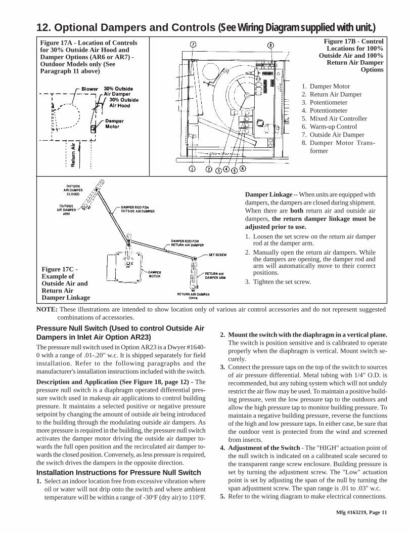
Mfg #163219, Page 11
1. Damper Motor2. Return Air Damper3. Potentiometer4. Potentiometer5. Mixed Air Controller6. Warm-up Control7. Outside Air Damper8. Damper Motor Trans-
former
Figure 17A - Location of Controlsfor 30% Outside Air Hood andDamper Options (AR6 or AR7) -Outdoor Models only (SeeParagraph 11 above)
Figure 17B - ControlLocations for 100%
Outside Air and 100%Return Air Damper
Options
Damper Linkage -- When units are equipped withdampers, the dampers are closed during shipment.When there are both return air and outside airdampers, the return damper linkage must beadjusted prior to use.1. Loosen the set screw on the return air damper
rod at the damper arm.2. Manually open the return air dampers. While
the dampers are opening, the damper rod andarm will automatically move to their correctpositions.
3. Tighten the set screw.
Figure 17C -Example ofOutside Air andReturn AirDamper Linkage
NOTE: These illustrations are intended to show location only of various air control accessories and do not represent suggestedcombinations of accessories.
12. Optional Dampers and Controls (See Wiring Diagram supplied with unit.)
Pressure Null Switch (Used to control Outside AirDampers in Inlet Air Option AR23)The pressure null switch used in Option AR23 is a Dwyer #1640-0 with a range of .01-.20" w.c. It is shipped separately for fieldinstallation. Refer to the following paragraphs and themanufacturer's installation instructions included with the switch.
Description and Application (See Figure 18, page 12) - Thepressure null switch is a diaphragm operated differential pres-sure switch used in makeup air applications to control buildingpressure. It maintains a selected positive or negative pressuresetpoint by changing the amount of outside air being introducedto the building through the modulating outside air dampers. Asmore pressure is required in the building, the pressure null switchactivates the damper motor driving the outside air damper to-wards the full open position and the recirculated air damper to-wards the closed position. Conversely, as less pressure is required,the switch drives the dampers in the opposite direction.
Installation Instructions for Pressure Null Switch1. Select an indoor location free from excessive vibration where
oil or water will not drip onto the switch and where ambienttemperature will be within a range of -30oF (dry air) to 110oF.
2. Mount the switch with the diaphragm in a vertical plane.The switch is position sensitive and is calibrated to operateproperly when the diaphragm is vertical. Mount switch se-curely.
3. Connect the pressure taps on the top of the switch to sourcesof air pressure differential. Metal tubing with 1/4" O.D. isrecommended, but any tubing system which will not undulyrestrict the air flow may be used. To maintain a positive build-ing pressure, vent the low pressure tap to the outdoors andallow the high pressure tap to monitor building pressure. Tomaintain a negative building pressure, reverse the functionsof the high and low pressure taps. In either case, be sure thatthe outdoor vent is protected from the wind and screenedfrom insects.
4. Adjustment of the Switch - The "HIGH" actuation point ofthe null switch is indicated on a calibrated scale secured tothe transparent range screw enclosure. Building pressure isset by turning the adjustment screw. The "Low" actuationpoint is set by adjusting the span of the null by turning thespan adjustment screw. The span range is .01 to .03" w.c.
5. Refer to the wiring diagram to make electrical connections.

Form 409, Page 12
13. Optional Evaporative Cooling ModuleEvaporative cooling provides excellent comfort cooling at low initial equipment and installation costs and low operating and maintenance costs.Direct evaporative cooling works solely on the principle that water in direct contact with a moving airstream will eventually evaporate if thedroplets have long enough exposure. This evaporative cooling module uses wetted rigid cellulose or rigid glass fiber media to retain water in orderto allow time for evaporation.
IMPORTANT: To eliminate shipping damage to the switch contacts, themanufacturer reduced the span adjustment to zero before shipping. Thespan should be adjusted prior to using the switch. (If the switch has beeninstalled, disconnect the vent tube so that the null switch is in a neutralposition.) Remove the electrical box cover and while observing the con-tacts, turn the span adjustment screw slowly in a clockwise direction.Continue turning the adjustment screw until you are able to see gapsbetween the common and both the low and high contacts. A minimumgap provides the greatest sensitivity. The wider the gap the lower thesensitivity.
Figure 18 - PressureNull Switch (used withInlet Air OptionAR23)
Model RBL - The evaporative cooling module for a Model RBLcabinet is factory assembled but is not attached to the blower cabi-net at the factory. It is shipped separately for field attachment to thesystem blower cabinet. The base support for the cooling moduleand the transitional ductwork between the cooling module and theblower cabinet inlet are shipped separately and must be field as-sembled and installed. Complete installation instructions includ-ing water and electrical connections are included with the evapo-rative cooling module package.
Included in the cooling module installation booklet is a prepara-tion checklist. All items in that checklist should be consulted prior
Figure 19 - Optional Evaporative Cooling Modulefor Model RBL Blower Cabinet is factory-assembledfor field attachment to the blower cabinet (duct andbase are shipped knocked down for field assembly)
Blower Cabinet
CoolingModuleand Base
Con
nect
ing
Duc
t
Figure 20 -OptionalEvaporativeCoolingModuleattached toa ModelRBABlowerCabinet
Optional Equipment (cont'd)12. Optional Dampers and Controls (cont'd)
to beginning installation of the optional evaporative cooling module. Fourof those items are listed below.� Make certain the roof or platform is capable of handling the additional
load of a full cooling module reservoir.Weights of Optional Evaporative Cooling Module with Wet Mediaand a Full Reservoir for Model RBL
Module with 6" rigid cellulose media (Option AS3) 349 lbsModule with 12" rigid cellulose media (Option AS4) 431 lbsModule with 6" rigid glass fiber media (Option AS5) 420 lbsModule with 12" rigid glass fiber media (Option AS6) 514 lbs
�Make certain the surface is level and free of debris where cooling mod-ule will be mounted.
�Do not mount directly on soft tar roofs where the legs could sink andtilt the cooler. Provide a weather-resistant, solid wood or metal baseunder cooling module support legs.
�Make certain that there will be adequate clearance between the bottomof the reservoir and the roof (or platform) to allow for drain and over-flow pipe connections.
Model RBA - Theevaporative coolingmodule for ModelRBA is a factory in-stalled cooling mod-ule as illustrated inFigure 20. Follow theinstructions in thisbooklet for makingwater and drain con-nections and mainte-nance.

Mfg #163219, Page 13
Media -- Both the factory-installed and the field-installed evaporativecooling modules are equipped with high efficiency pad media of ei-ther 6" or 12" rigid cellulose (Option AS3 or AS4) or 6" or 12" rigidglass fiber (Option AS5 or AS6). Six-inch media provides 68% effi-ciency; 12" media provides 90% efficiency. Efficiency values are statedat maximum allowable CFM without the addition of a moisture elimi-nation pad with an inlet dry bulb temperature of 95oF and inlet wetbulb temperature of 65oF. The evaporative cooling efficiency is a func-tion of inlet temperature and of face velocity through the media. Thestated cooling efficiency will rise with the decrease of CFM and theincrease of inlet temperature. Moisture elimination pad (Option ASA1)may be used on all units but is required on Model RBA with over 3200CFM and Model RBL with over 11,200 CFM (950 FPM). Moistureelimination pads are factory installed in factory-installed cooling mod-ules (Model RBA) and are shipped separately for field installation inevaporative cooling modules for RBL models. Installation instructionsare included.
SimulatesSide Panel
Use 1/4"Tubing forFresh WaterSupply
Compression Nutand Tubing Ferrule(Inside
Cabinet)
FloatValveRod
Figure 21 -Connect FreshWater Supply toInlet of FloatValve
Supply and Drain Water ConnectionsFloat Valve (Figure 21) - In a module with pump and float controls, afloat valve maintains the appropriate water level in the reservoir.
Use a field-supplied 1/4" diameter tubing with a compression nut andtubing ferrule to connect the fresh water supply to the inlet of the floatvalve. See Figure 21. Place nut and ferrule over tubing and insert tub-ing into the float valve stem. Tighten nut securely.
AquaSaver® Timed Metering Control System - If the cooling mod-ule is equipped with an optional timed metering system, connect a 1/2"water line to the fitting on the side of the cooling module.Due to various water pressures and installation conditions, the watersuppy line may bang abruptly when the solenoid valve in the AquaSaversystem closes. This banging can be minimized by installing an optionalwater hammer arrestor in the supply line. When installing an optionalwater hammer arrestor, select an indoor (above 32oF) location., eitherhorizontal or vertical, in line with and as close to the solenoid valve aspossible. Follow the manufacturer's instructions to install and maintainthe water hammer arrestor.All Cooling Modules -A manual water shutoff valve should be in-stalled upstream of the cooling module inlet, at a convenient non-freez-ing location, to allow the water supply to be turned on and off. If nec-essary, install a bleed line between the manual valve and the coolingmodule to allow drainage of the line between the shutoff valve and thecooling module.
WARNING: Water reservoir (outdoor systems)must be drained and pump motor turned offwhen outside temperature falls below 32oF. Pumpmust never be operated without water in thereservoir. See Hazard Levels, page 1.
All cooling modules are equipped with an overflow and drain fitting.The fittings are in the cabinet bottom and come complete with a locknut and a sealing gasket. Check these fittings for tightness before in-stalling the overflow and drain piping. The drain and overflow fittingwill accommodate a 3/4" garden hose thread and is tapped with a 1/2"female pipe thread for iron pipe.An optional automatic fill and drain kit (Option CT) is available thatwill automatically release supply water to the cooling module when acall for cooling is made and drain all water from the reservoir when thecooling switch is deactivated or a cooling thermostat is satisfied. SeeFigure 22. Follow the instructions below if installing an optional filland drain kit. Consult wiring diagram for electrical connections.Instructions for Installing Optional Fill & Drain KitNOTE: Follow instructions included in the valve packages for attachingvalves to the water line only. The remainder of the installation instruc-tions with the valves does not apply to this type of application.
Figure 22 - Water Connectionsincluding Optional Drain and Fill Kit
Water Line Connections (See Figure 22):Supply (3-Way Valve) Connections - Connect the watersupply line to "B" (normally closed). Connect the water drainline to "A" (normally open). Connect the middle outlet tosupply the water to the cooling module reservoir.Drain (2-Way Valve) Connections - Connect the drain pipefrom the reservoir to "A". Connect the outlet side to "B"and connect into drain lines from the cooling reservoir andthe supply valve.Electrical Connections (requires black and white 14-gauge wire) - Refer to Wiring Diagram on the furnace:
WARNING: Risk of electrical shock. Disconnectthe power.1. Refer to the wiring diagram for terminal connections.
(NOTE: If kit is not ordered with the system, connec-tions will not be shown on the diagram. Terminal con-nections are specific to each system. Contact the fac-tory for terminal connections. Be prepared to provideall model information. )
2. Run field-supplied black wire from the electrical com-partment (terminal on the wiring diagram) of the evapo-rative cooling module and connect to the black wire onboth the 3-way and the 2-way valve.
3. Run field-supplied white wire from the electrical com-partment (terminal on the wiring diagram) of the evapo-rative cooling module and connect to the white wire onboth the 3-way and the 2-way valve.

Form 409, Page 14
Figure 23 - BleedLine Connection
Bleed Line Connection (Does not apply to module with optional timedmetering system.) --Shipped in the evapora-tive cooling module bot-tom pan, find a 1/4" I.D.x 1/2" N.P.T. nylon bleedline fitting (hose barb).Thread the fitting intothe female adapter lo-cated opposite the pump/inlet side of the waterdistribution line. Thehose barb will protrudefrom the side of the cabi-net (See Figure 23). At-tach a 1/4" I.D. hose tothe barb and run the hoseto the nearest drain.Discharging a quantityof water by "bleed off"will limit the concentration of undesirable minerals in the water be-ing circulated through the cooling module. Minerals buildup becauseevaporation only releases "pure water vapor" causing the concentra-tion of contaminants in the water to increase as the evaporation pro-cess continues to occur. The minerals accumulate on the media, in thewater lines, on the pump, and in the reservoir. Adequate bleed off isimportant to maintaining an efficiently operating evaporative coolingsystem.
Filling & Adjusting the Water Level in the ReservoirFloat and Pump Control System -- Turn on the water supply. Checkfor good flow.When the float valve (Figure 21) shuts off the water supply, measurethe water depth. The depth of the water should be approximately 3". Itmay be necessary to adjust the float valve to obtain the proper waterlevel or to free the float valve from obstructions. To adjust the floatvalve, simply bend the rod upward to raise the water level or down-ward to decrease the water level.
Adjusting Water Flow Over PadsProper water flow over the evaporative cooling media is critical toextend the life and maintain the efficiency of the pads. Follow theinstructions to adjust water flow. After the first week of operation, thewater flow should be re-checked because the soaker hose weave willtighten slightly affecting the water flow.
CAUTION: Do not flood the media pads withextreme quantities of water for long periods as thiswill cause premature breakdown of the media. Aneven flow from top to bottom of the media with theleast amount of water is all that is required to assuremaximum efficiency and media life span. More waterdoes not provide more evaporation or more cooling.
Float and Pump Control System -- Using the ball valve, located inthe middle of the length ofhose running from the pumpto the distribution line inlet(Figure 24), adjust the valvehandle to allow the flow tocompletely dampen the me-dia pads from top to bottom.Operate the unit watchingthe water flow. After 15 min-
InstalltheHoseBarbandAttachBleedLine
AquaSaver® Timed Metering Control System -- NOTE: Water flowand pad wetting time should be adjusted at maximum air flow and wetbulb depression to assure complete wetting of the media at the extremeoperating conditions.In addition to adjusting water flow, the timing of the water on/off cyclecan be adjusted. Adjustments are correct when l) the water rises fromthe holes in the soaker hose (See Figure 25A) consistently along theentire hose length, 2) the media pads wet evenly after a few "ON"cycles (no dry spots or dry streaks), and 3) a slight amount of excesswater collects at the drain at the completion of the "ON" cycle.
1) AquaSaver® Water Flow Adjustment - Using the ball valve illus-trated in Figure 24, adjust the water flow depending on the pad height.See Figure 25A.
2) AquaSaver® Timer Adjustment - At any given temperature, themedia pads should completely wet from top to bottom during the ONcycle. If the ON time is less than 45 seconds or greater than 90 secondsat 80oF, adjust the timer. Remove the junction box cover to access thetimer adjustment screw (See Figure 25B).
Through the use of a bimetallic strip, the timer is temperature sensitiveand automatically increases the ON time approximately one second foreach 1oF rise above the 80o factory setting. The ON time will equal thesetting for 80oF plus a second for each degree above 80.
Let the unit cycle a few times to verify that the water flow is correct andthe soaker hose is operating properly to wet the media pads completelyfrom top to bottom during the ON cycle.
All Modules -- Check the reservoir for any water leaks. The reservoirwas water tested, but if any small leaks are present, drain the reservoirand apply a waterproof silicone sealer around corners and welds.
utes with the blower in operation, the water should have completelydampened the pads but should not be flowing off the entering side ofthe media. If water is flowing off the entering side of the media, turnthe system off, disconnect the power, and reduce the entering waterflow.
WARNING: Adjust ball valve only when thepower is disconnected from the system. Failureto do so can cause electrical shock, personalinjury or death.
13. Optional Evaporative Cooling Module (cont'd)
Figure 24 -Disconnectthe powerand useball valveto adjustwater flow
BallValve
Pad A = Water riseHeight from Soaker Hose
24" 1/8" to 1/2"
48" 1/4" to 1/2"
Figure 25A - Adjust Water Flow with the BallValve in Figure 24
SoakerHose
Figure 25B - Junction Box with AquaSaver® Controls
TimerAdjustment
— To increase the ON time, turn theadjustment screw clockwise; onecomplete turn will increase ONcycle by 12 to 14 seconds.
— To decrease the ON time, turn theadjustment screw counterclock-wise; one complete turn willdecrease ON cycle by 12 to 14
Mfg #163219, Page 15
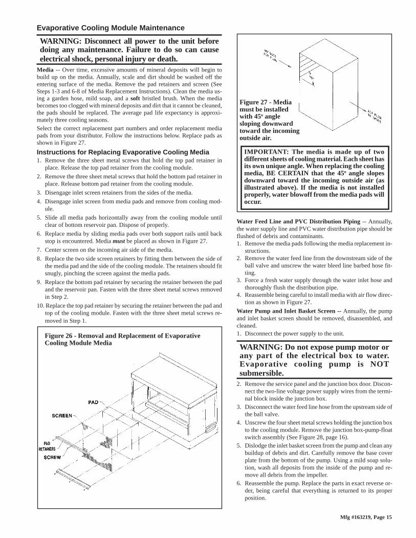
IMPORTANT: The media is made up of twodifferent sheets of cooling material. Each sheet hasits own unique angle. When replacing the coolingmedia, BE CERTAIN that the 45o angle slopesdownward toward the incoming outside air (asillustrated above). If the media is not installedproperly, water blowoff from the media pads willoccur.
Figure 27 - Mediamust be installedwith 45o anglesloping downwardtoward the incomingoutside air.
Evaporative Cooling Module Maintenance
WARNING: Disconnect all power to the unit beforedoing any maintenance. Failure to do so can causeelectrical shock, personal injury or death.
Media -- Over time, excessive amounts of mineral deposits will begin tobuild up on the media. Annually, scale and dirt should be washed off theentering surface of the media. Remove the pad retainers and screen (SeeSteps 1-3 and 6-8 of Media Replacement Instructions). Clean the media us-ing a garden hose, mild soap, and a soft bristled brush. When the mediabecomes too clogged with mineral deposits and dirt that it cannot be cleaned,the pads should be replaced. The average pad life expectancy is approxi-mately three cooling seasons.Select the correct replacement part numbers and order replacement mediapads from your distributor. Follow the instructions below. Replace pads asshown in Figure 27.
Instructions for Replacing Evaporative Cooling Media1. Remove the three sheet metal screws that hold the top pad retainer in
place. Release the top pad retainer from the cooling module.
2. Remove the three sheet metal screws that hold the bottom pad retainer inplace. Release bottom pad retainer from the cooling module.
3. Disengage inlet screen retainers from the sides of the media.
4. Disengage inlet screen from media pads and remove from cooling mod-ule.
5. Slide all media pads horizontally away from the cooling module untilclear of bottom reservoir pan. Dispose of properly.
6. Replace media by sliding media pads over both support rails until backstop is encountered. Media must be placed as shown in Figure 27.
7. Center screen on the incoming air side of the media.
8. Replace the two side screen retainers by fitting them between the side ofthe media pad and the side of the cooling module. The retainers should fitsnugly, pinching the screen against the media pads.
9. Replace the bottom pad retainer by securing the retainer between the padand the reservoir pan. Fasten with the three sheet metal screws removedin Step 2.
10. Replace the top pad retainer by securing the retainer between the pad andtop of the cooling module. Fasten with the three sheet metal screws re-moved in Step 1.
Figure 26 - Removal and Replacement of EvaporativeCooling Module Media
Water Feed Line and PVC Distribution Piping -- Annually,the water supply line and PVC water distribution pipe should beflushed of debris and contaminants.1. Remove the media pads following the media replacement in-
structions.2. Remove the water feed line from the downstream side of the
ball valve and unscrew the water bleed line barbed hose fit-ting.
3. Force a fresh water supply through the water inlet hose andthoroughly flush the distribution pipe.
4. Reassemble being careful to install media with air flow direc-tion as shown in Figure 27.
Water Pump and Inlet Basket Screen -- Annually, the pumpand inlet basket screen should be removed, disassembled, andcleaned.1. Disconnect the power supply to the unit.
WARNING: Do not expose pump motor orany part of the electrical box to water.Evaporative cooling pump is NOTsubmersible.
2. Remove the service panel and the junction box door. Discon-nect the two-line voltage power supply wires from the termi-nal block inside the junction box.
3. Disconnect the water feed line hose from the upstream side ofthe ball valve.
4. Unscrew the four sheet metal screws holding the junction boxto the cooling module. Remove the junction box-pump-floatswitch assembly (See Figure 28, page 16).
5. Dislodge the inlet basket screen from the pump and clean anybuildup of debris and dirt. Carefully remove the base coverplate from the bottom of the pump. Using a mild soap solu-tion, wash all deposits from the inside of the pump and re-move all debris from the impeller.
6. Reassemble the pump. Replace the parts in exact reverse or-der, being careful that everything is returned to its properposition.

Form 409, Page 16
©1999 Thomas & Betts Corporation, All rights reserved. Printed in the U.S.A.MANUFACTURER OF GAS, OIL, ELECTRIC HEATING AND VENTILATING SYSTEMS399 2.5M WE Form RGM409.3
WARNING: Disconnect the power before servicing the cooling module. Failure to do so can causeelectrical shock, personal injury or death.
Pump
Junction Box (Note:Only 208V unit willhave a transformer inthe junction box.)
FloatSwitch
PumpMotor
Figure 28 - Remove Junction Box, Pump and FloatSwitch as an Assembly
Carefully removebasket and snap-oncover plate to cleanpump
13. Optional Evaporative Cooling Module (cont'd)
Troubleshooting Evaporative Cooling Module
Proble m Probable C ause Reme dyPump does not run. U nit is 1. Elect rical connect ions 1. Verify all elect rical connect ions. See Wiring D iagram.calling for cooling (i.e. console 2. Elect ric float sw itch on p ump 2. Check p osit ion of the actuators on the elect ric float sw itch.control sw itch is in cooling 3. D irty p ump 3. Clean p ump . See Figure 28.p osit ion) and reservoir is full. 4. D efect ive p ump 4. Rep lace p ump .Required w ater level (3") not 1. Float valve 1. A djust float valve. See F illing and A djus ting Water Level.maintained 2. O p t ional drain and fill valves 2. Check valve for p rop er op erat ion. See Figure 22.
3. Incorrect overflow p ip e nip p le - should be 3-1/2"
3. Rep lace p ip e nip p le.
4. D rain leaking 4. T ighten drain p lug.Water running off of media 1. Excessive w ater flow 1. A djust ball valve in dist ribut ion line. See A djust Water Flow .p ads 2. M edia p ads need cleaned or
rep laced. 2. Clean or rep lace media p ads. See Evap orat ive Cooling M odule M aintenance.
Water not dist ribut ing evenly 1. D is tribut ion line clogged 1. Flush dist ribut ion line. See Evap Cooling M odule M aintenance.2. H oles in dist ribut ion line turned 2. Check p osit ion of dist ribut ion line. H oles should be sp ray ing
up w ard. If not p osit ioned w ith holes tow ard top , adjust p os it ion of PVC line.
3. Incorrect voltage to p ump 3. Check voltage at p ump terminal in cooling module junct ion box.M edia p ads becoming clogged 1. Bleed off line clogged 1. Clean bleed line. See F igure 23.and discolored quickly (scale/salt dep osits) and/or
2. Excessive w ater flow 2. Reduce flow by adjust ing ball valve in dist ribut ion line. See Filling and A djust ing Water Level.
rap id deteriorat ion of the float sw itch
3. Inadequate bleed off 3. A uniform build-up of minerals on the entering air face of the media indicates insufficient bleed off. Increase the rate unt il the mineral dep os its dissip ate.
Water blow off from media 1. M edia p ads ins talled incorrect ly 1. Install media p ads correct ly . See Evap Cooling M odule M aintenance.p ads 2. Requires moisture eliminat ion
p ad (over 600 FPM )2. Install moisture eliminat ion p ad. Consult factory .
3. Water level not 3 inches 3. See second p roblem listed above (Required w ater level)