BIOREACTOR DESIGN FOR VASCULAR TISSUE ENGINEERING · PDF fileBIOREACTOR DESIGN FOR VASCULAR...
95
Project Number: MR1-0801 BIOREACTOR DESIGN FOR VASCULAR TISSUE ENGINEERING A Major Qualifying Project Report Submitted to the Faculty Of the WORCESTER POLYTECHNIC INSTITUTE In partial fulfillment of the requirements for the Degree of Bachelor of Science by ______________________________ Lauren Ferrechio ______________________________ Andres Lopez ______________________________ Jordan Skelly ______________________________ Jennifer Thompson Date: April 30, 2009 Approved: 1. Bioreactor 2. Blood Vessels 3. Tissue Engineering ________________________________ Prof. Marsha Rolle, PhD, Major Advisor
Transcript of BIOREACTOR DESIGN FOR VASCULAR TISSUE ENGINEERING · PDF fileBIOREACTOR DESIGN FOR VASCULAR...

Project Number: MR1-0801
BIOREACTOR DESIGN FOR VASCULAR TISSUE ENGINEERING
A Major Qualifying Project Report
Submitted to the Faculty
Of the
WORCESTER POLYTECHNIC INSTITUTE
In partial fulfillment of the requirements for the
Degree of Bachelor of Science
by
______________________________
Lauren Ferrechio
______________________________
Andres Lopez
______________________________
Jordan Skelly
______________________________
Jennifer Thompson
Date: April 30, 2009
Approved:
1. Bioreactor
2. Blood Vessels
3. Tissue Engineering
________________________________
Prof. Marsha Rolle, PhD, Major Advisor

i
Table of Contents Authorship.......................................................................................................................... iv
Acknowledgements ............................................................................................................. v
Abstract .............................................................................................................................. vi
Table of Figures ................................................................................................................ vii
Table of Tables .................................................................................................................. ix
1.0 Introduction ................................................................................................................... 1
2.0 Literature Review.......................................................................................................... 5
2.1 Coronary Heart Disease ............................................................................................ 5
2.2 Physiology and Mechanics of Blood Vessels ........................................................... 6
2.3 Graft Replacement Sources ....................................................................................... 8
2.3.1 Autologous Grafts............................................................................................... 8
2.3.2 Synthetic Grafts .................................................................................................. 9
2.3.3 Tissue Engineered Grafts .................................................................................... 9
2.4 Patents ..................................................................................................................... 13
2.4.1 Patent # US 7,112,218 B2 ................................................................................ 13
2.4.2 Patent # US 20,060,240,061 A1 ....................................................................... 14
2.4.3 Patent Application # US 20,070,128,171 ......................................................... 14
2.5 Gaps in Current Technology ................................................................................... 15
3. 0 Project Strategy .......................................................................................................... 17
3.1 Initial Client Statement............................................................................................ 17
3.2 Objectives & Constraints ........................................................................................ 18
3.2.1 Bioreactor ......................................................................................................... 18
3.2.2 Vascular Grafts ................................................................................................. 19
3.3 Revised Client Statement ........................................................................................ 20
3.4 Needs Analysis ........................................................................................................ 20
3.5 Bioreactor Functions ............................................................................................... 21
3.6 Project Approach ..................................................................................................... 22
4.0 Alternative Designs ..................................................................................................... 23
4. 1 Structure to Assemble Cells ................................................................................... 23
ii
4.1.1 Mandrel Designs ............................................................................................... 24
4.1.2 Mechanical Mandrel ......................................................................................... 27
4.2 Method to Assemble and Culture Cells................................................................... 29
4.2.1 Static Seeding ................................................................................................... 29
4.2.2 Manual Rotation ............................................................................................... 30
4.2.3 Automated Rotation System ............................................................................. 30
4.2.4 Pump/Vacuum System ..................................................................................... 30
4.3 Housing to Culture and Monitor Tissue .................................................................. 31
4.3.1 Tubular Construct Orientation .......................................................................... 32
4.3.2 Cartridge Designs ............................................................................................. 32
5.0 Design Verification ..................................................................................................... 34
5.1 Verification of Support Structure ............................................................................ 35
5.1.1 Verification Using Hanging Drop Method ....................................................... 37
5.1.2 Verification Using the V-Well method ............................................................ 42
5.2 Verification of Cell Assembly and Culture Methods .............................................. 44
5.3 Verification of Housing to Culture and Monitor Cells ........................................... 49
6. 0 Final Design and Validation ...................................................................................... 52
6.1 Construction of the Bioreactor ................................................................................ 52
6.2 Validation of Final Design ...................................................................................... 55
6.2.1 Flow Testing Using Colored Dye ........................................................................ 55
7.0 Discussion ................................................................................................................... 58
7.1 Bioreactor Design .................................................................................................... 58
7.1.1 Mandrel Choice ................................................................................................ 58
7.1.2 Cartridge Shape ................................................................................................ 58
7.1.3 Vacuum and Cell Seeding ................................................................................ 59
7.2 Economic Impact..................................................................................................... 59
7.3 Environmental Impact ............................................................................................. 60
7.4 Societal Influence .................................................................................................... 60
7.5 Political Ramifications ............................................................................................ 60
7.6 Ethical Concern ....................................................................................................... 61
7.7 Health and Safety Issues ......................................................................................... 61

iii
7.8 Manufacturability .................................................................................................... 61
7.9 Sustainability ........................................................................................................... 62
8.0 Conclusions and Recommendations ........................................................................... 63
8.1 Design Choice ......................................................................................................... 63
8.2 Future Recommendations ........................................................................................ 63
Works Cited ...................................................................................................................... 65
Works Referenced ............................................................................................................. 69
Glossary ............................................................................................................................ 70
Appendixes ....................................................................................................................... 71
APPENDIX A: Pairwise Comparison Charts ............................................................... 71
Vascular Grafts .......................................................................................................... 71
APPENDIX B: Functions/Means Morphological Chart ............................................... 72
APPENDIX C: Decision Matrixes ................................................................................ 73
Mandrel Type ............................................................................................................ 73
Cell Seeding Method ................................................................................................. 74
Cartridge Shape ......................................................................................................... 75
APPENDIX D: Protocols .............................................................................................. 76
Harvest of Fibers from Cartridge ............................................................................... 76
Video Camera resolution/suitability test ................................................................... 77
Polycarbonate Optics tests ......................................................................................... 78
Bioreactor .................................................................................................................. 79
Hanging Drop Experiment 2...................................................................................... 82
Cartridge Seeding Protocol ........................................................................................ 84
APPENDIX E: Bill of Materials ................................................................................... 85

iv
Authorship
All four team members contributed to and reviewed all sections of this report and
therefore we jointly accept responsibility for the project and decline the option of
individual authorships.

v
Acknowledgements
The team gratefully acknowledges Marsha Rolle, Tracy Gwyther, Kshama Doshi,
Lisa Wall, Amanda Zoe Reidinger and Jason Hu for help with obtaining materials,
answering questions and cell culturing techniques. The team would also like to thank Neil
Whitehouse for his help machining the bioreactor pieces. The team also thanks Brendan
McMasters, Adrianna Hera, and Brian Savilonis for their help modeling the device using
Fluent. The team would like to thank the Biology Department, particularly Mike
Buckholt and Dan Gibson, for their help and the use of their equipment. The team would
also like to thank the MQP team of Jason Hu, Shawn Carey, Jonathan Charest and
Elizabeth Ellis, who shared their designs of creating a V-shaped well, which was used in
cell testing.

vi
Abstract
Currently, there is an urgent clinical need for blood vessel replacements,
especially in small diameter applications. Tissue engineered vascular grafts take months
to culture and require extensive graft manipulation. The purpose of this project was to
design a bioreactor which would output small diameter tubular and completely cellular
vascular grafts. A cartridge was designed as a housing for five hollow, porous fibers used
as support structures for the growth of cells seeded into the bioreactor. A pump was used
to create a dynamic culture system and to facilitate cell seeding onto the fibers with the
use of a vacuum force. The design was validated by analyzing the fluid flow and forces
generated. Computer modeling and physical flow testing indicate that the bioreactor is
suitable for cell seeding and vascular graft production. Future analysis of fiber materials
will focus on more accurate modeling of fluid flow and assessment of cell seeding and
vascular graft assembly.

vii
Table of Figures
FIGURE 2.1: CORONARY ARTERY BYPASS GRAFT ......................................................................................................... 6 FIGURE 2.2: STRUCTURE OF A MEDIUM-SIZED BLOOD VESSEL ............................................................................ 7 FIGURE 2.3: AUTOLOGOUS GRAFT REPLACEMENT...................................................................................................... 8 FIGURE 2.4: SYNTHETIC GRAFT REPLACEMENT ........................................................................................................... 9 FIGURE 2.5: LIFELINE GRAFT................................................................................................................................................ 10 FIGURE 2.6 ROLLING MANDREL (MCALLISTER ET AL, 2006) ............................................................................... 14 FIGURE 2.7: DRAWING OF TRANQUILLO'S LAYERED TISSUE ENGINEERED BLOOD VESSEL ................ 15 FIGURE 3.1: BIOREACTOR OBJECTIVES ............................................................................................................................ 18 FIGURE 3.2: VASCULAR GRAFT OBJECTIVES ................................................................................................................. 19 FIGURE 3.3: WEIGHTED OBJECTIVE TREE BASED ON NEEDS ANALYSIS ........................................................ 21 FIGURE 3.4: THREE FUNCTION GROUPS OF BIOREACTOR ..................................................................................... 22 FIGURE 4.1: BIOREACTOR SCHEMATIC ............................................................................................................................ 23 FIGURE 4.2: STRUCTURE TO ASSEMBLE CELLS ........................................................................................................... 24 FIGURE 4.3: MANDREL DESIGNS ......................................................................................................................................... 25 FIGURE 4.4: FIBERCELL CARTRIDGE ................................................................................................................................. 26 FIGURE 4.5: OXYGEN, NUTRIENT AND WASTE FLOW THROUGH FIBERS ....................................................... 26 FIGURE 4.6: FLAT MANDREL BEFORE ROLLING .......................................................................................................... 28 FIGURE 4.7: MECHANICAL MANDREL ROLLED ............................................................................................................ 28 FIGURE 4.8: METHOD TO ASSEMBLE AND CULTURE CELLS .................................................................................. 29 FIGURE 4.9: CELL ATTACHMENT TO SURFACE ............................................................................................................ 31 FIGURE 4.10: HOUSING TO CULTURE AND MONITOR TISSUE .............................................................................. 32 FIGURE 4.11: CARTRIDGE SHAPES ..................................................................................................................................... 32 FIGURE 4.12: CYLINDRICAL CARTRIDGE DESIGN ....................................................................................................... 33 FIGURE 4.13: FLAT CARTRIDGE DESIGN ......................................................................................................................... 33 FIGURE 5.1: SOLIDWORKS CARTRIDGE ........................................................................................................................... 34 FIGURE 5.2: MAGNIFIED FIBERS (HYDRATED AND DEHYDRATED) .................................................................. 35 FIGURE 5.3: MATERIALS USED TO OPEN FIBERCELL CARTRIDGE ..................................................................... 36 FIGURE 5.4: PDMS RING ATTACHED TO FIBER ............................................................................................................ 38 FIGURE 5.5: HANGING DROP PLATES................................................................................................................................ 39 FIGURE 5.6: MEDIA IN A HANGING DROP WELL .......................................................................................................... 40 FIGURE 5.7: INCONSISTENCY OF METHOD .................................................................................................................... 41 FIGURE 5.8: V-WELL METHOD ............................................................................................................................................ 42 FIGURE 5.9: UNSEEDED AND SEEDED CELL TRACKER FIBERS ............................................................................ 43 FIGURE 5.10: FLUENT 2-D ...................................................................................................................................................... 44 FIGURE 5.11: FLOW AROUND EACH FIBER .................................................................................................................... 45 FIGURE 5.12: FIBER 1 ................................................................................................................................................................ 46 FIGURE 5.13: FIBER 5 ................................................................................................................................................................ 46 FIGURE 5.14: FIBERS 2 AND 4 ............................................................................................................................................... 47 FIGURE 5.15: FIBER 3 ................................................................................................................................................................ 47 FIGURE 5.16: FLOW THROUGH TWO INLETS ................................................................................................................ 48 FIGURE 5.17: FLOW THROUGH EACH FIBER ................................................................................................................. 49 FIGURE 5 18: BIOREACTOR WITH MEDIA ....................................................................................................................... 50 FIGURE 6.1: COMPLETED BIOREACTOR .......................................................................................................................... 52 FIGURE 6.2: DISASSEMBLED CARTRIDGE ....................................................................................................................... 53 FIGURE 6.3: ASSEMBLED CARTRIDGE .............................................................................................................................. 54 FIGURE 6.4:CARTRIDGE WITH LUER FITTINGS ........................................................................................................... 54

viii
FIGURE 6.5: MEDIA RESERVOIR........................................................................................................................................... 55 FIGURE 6.6: DYE SIMULATION OF LONGITUDINAL FLOW PATH ........................................................................ 56 FIGURE 6.7: CELL SEEDING USING DYE SIMULATION ............................................................................................... 57 FIGURE 6.8: VACUUM SEEDING FLOW PATH ................................................................................................................. 57

ix
Table of Tables TABLE 3.1: BIOREACTOR FUNCTIONS .............................................................................................................................. 21

1
1.0 Introduction
Currently, there is an urgent clinical need for vascular grafts, especially for small
diameter (<6mm) applications. Small diameter grafts are commonly used in arterial
bypass surgeries and in 2005 alone, 600,000 arterial bypass surgeries were performed
(Antman et. al., 2004). Additionally, small diameter vascular grafts are needed for
dialysis fistulas and lower limb vessel replacements. The use of autologous grafts, tissues
transplanted from one area in the human body to another, requires an additional surgery.
Also, many patients lack suitable autologous vessels due to age, disease, or previous
harvest (Schmelden et al., 2003). When suitable autologous vessels are unavailable,
completely synthetic grafts have been used. Although these synthetic grafts may be
suitable for large-diameter applications, synthetic grafts are highly susceptible to clotting
when used for small diameter applications (Harbuzariu et al, 2007). There are three main
categories for grafts including synthetic, autologous and tissue engineered.
A number of tissue engineered grafts have been explored, but currently there is
not an abundance of available grafts. The majority of current tissue engineering
approaches involves the use of exogenous scaffolds, made of synthetic polymers, protein
hydrogels, crosslinked proteins, or decellularized native tissues (Stegemann et al, 2007).
Cells seeded into these exogenous scaffolds are cultured in vitro until suitable biological
and mechanical function is achieved. The scaffolds are intended to provide mechanical
support and biochemical cues so that the cells will grow into functional vessels, but there
are many difficulties encountered by using exogenous scaffolds. The use of exogenous
scaffolds often leads to inconsistent degradation rates, compliance mismatch between the
old and new vessels, and a lack of biocompatibility. Although exogenous scaffolds are
not as elaborate as cell based grafts, the complexities of these scaffolds make them
difficult to manufacture due to their size, materials and specific surface geometry. An
alternative approach to using exogenous scaffolds involves stimulating the cells to self
assemble their own scaffold or extra cellular matrix (ECM) (Sun et al, 2005). In order to
create a tissue engineered vascular graft without complications common to exogenous
scaffolds, a graft should be developed that is completely cell-derived.
2
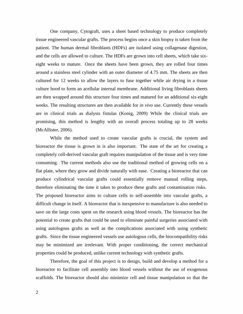
One company, Cytograft, uses a sheet based technology to produce completely
tissue engineered vascular grafts. The process begins once a skin biopsy is taken from the
patient. The human dermal fibroblasts (HDFs) are isolated using collagenase digestion,
and the cells are allowed to culture. The HDFs are grown into cell sheets, which take six-
eight weeks to mature. Once the sheets have been grown, they are rolled four times
around a stainless steel cylinder with an outer diameter of 4.75 mm. The sheets are then
cultured for 12 weeks to allow the layers to fuse together while air drying in a tissue
culture hood to form an acellular internal membrane. Additional living fibroblasts sheets
are then wrapped around this structure four times and matured for an additional six-eight
weeks. The resulting structures are then available for in vivo use. Currently these vessels
are in clinical trials as dialysis fistulas (Konig, 2009) While the clinical trials are
promising, this method is lengthy with an overall process totaling up to 28 weeks
(McAllister, 2006).
While the method used to create vascular grafts is crucial, the system and
bioreactor the tissue is grown in is also important. The state of the art for creating a
completely cell-derived vascular graft requires manipulation of the tissue and is very time
consuming. The current methods also use the traditional method of growing cells on a
flat plate, where they grow and divide naturally with ease. Creating a bioreactor that can
produce cylindrical vascular grafts could essentially remove manual rolling steps,
therefore eliminating the time it takes to produce these grafts and contamination risks.
The proposed bioreactor aims to culture cells to self-assemble into vascular grafts, a
difficult change in itself. A bioreactor that is inexpensive to manufacture is also needed to
save on the large costs spent on the research using blood vessels. The bioreactor has the
potential to create grafts that could be used to eliminate painful surgeries associated with
using autologous grafts as well as the complications associated with using synthetic
grafts. Since the tissue engineered vessels use autologous cells, the biocompatibility risks
may be minimized are irrelevant. With proper conditioning, the correct mechanical
properties could be produced, unlike current technology with synthetic grafts.
Therefore, the goal of this project is to design, build and develop a method for a
bioreactor to facilitate cell assembly into blood vessels without the use of exogenous
scaffolds. The bioreactor should also minimize cell and tissue manipulation so that the
3
vessels can be produced both quickly and easily. The completely biological vascular
grafts should be approximately 2mm in diameter, 5cm in length, and 250 µm in wall
thickness, consequently the bioreactor should be designed to fulfill these requirements.
Designing and building a bioreactor that could use a patient’s own cells to produce
multiple grafts would allow for testing of the grafts to make sure they are ready to be
implanted. Since it is likely not all the grown vessels would be necessary for graft
replacement, any additional could be used to test the properties. Multiple graft
reproduction is also important for the research standpoint, where different aspects of the
graft would be investigated requiring multiple grafts to be tested. The bioreactor should
also be adaptable for different size specifications that may be required in the future.
In order to design and build a bioreactor there were certain steps that needed to be
completed to verify that the design fits the desired outcomes the most effectively. The
design method that was used was a five step process revised from Engineering Design: A
Project-Based Introduction written by Clive Dym and Patrick Little. The steps were
based on the initial client statement from which the problem definition, conceptual
design, preliminary design, detailed design, and design communication led to the final
design.
The first stage, the problem definition, took the client statement to first clarify the
design objectives, establish the user requirements and functions and to identify the
constraints. The revised client statement, objectives, constraints, user requirements and
functions, which will be described later in Chapter 3.0, were established next. The design
specifications and design alternatives were used to generate the conceptual designs,
which had several aspects, including a mandrel to seed cells on, a method to seed the
cells and a system to grow the cells in. During the preliminary design stage, which was
the stage that a final design was chosen, testing and evaluation of the results were
completed to determine which aspects would be included in the final design. During the
fourth stage, the detailed design, the final design was refined based on testing and the
proposed fabrication specifications were determined. Ultimately, the fifth and final stage
was the design communication stage in which the design was documented and submitted
to the client.
4
Prior to the design stages, related topics were researched in order to understand
the client statement and define it more clearly. An in-depth patent search was also
conducted in order to ensure that the design was original and no similar devise had been
patented. Sections of the paper were also included to describe the effects the project may
have on aspects such as the environment and the economy. Finally, future
recommendations were made so that improvements can be made to the design in the
future based on the results and conclusions that were determined.

5
2.0 Literature Review
Small-diameter graft replacements have become increasingly essential in recent
years as hospital stays and the money spent on Coronary Heart Disease (CHD) has
increased significantly (Shaw, 2006). Although synthetic and autologous grafts have
proven to be adequate, there is a growing need for a completely cell derived small-
diameter vascular grafts to minimize complications and reduce costs. Clinical trials have
proven that completely cell derived small-diameter vascular grafts have minimal side
effects and complications that have been common in patients with synthetic grafts
(McAllister, 2006).
2.1 Coronary Heart Disease
Coronary Heart Disease, affecting the vasculature of the heart, was the cause of
one out of every five deaths in the U.S. year 2005 (National Center for Health Statistics,
2005). Nearly 450,000 Americans died from the disease in the year 2005. A higher
proportion of men have cardiovascular disease than women, one in six women have the
disease. In 2005, the disease accounted for one out of every 2.7 deaths for women
(National Center for Health Statistics, 1979-2005). While life style choices have been
shown to increase or decrease the risk of developing coronary heart disease, many
Americans also inherit genes that increase their risk (Stampfer et al, 2000).
An estimated 8 million Americans have had a myocardial infarction, out of a total
of almost 17 million Americans that have been diagnosed with at least one type of
coronary heart disease (Lloyd-Jones et al, 2009). Myocardial infarction is a common
result of coronary heart disease. Infarct occurs when a blockage in the coronary artery
cuts off blood flow to part of the heart. The resulting blockage can lead to the death of the
distal heart tissue. In order to repair this condition, a common solution is to use a
coronary artery bypass graft (CABG), which bypasses the blockage and restores blood
flow to the affected tissue, as seen in Fig. 2.1. Small diameter vascular grafts are used in
patients with coronary heart disease to bypass blockages in the coronary arteries and
restore blood flow to the heart.

6
Figure 2.1: Coronary Artery Bypass Graft
Found at: http://www.nlm.nih.gov/medlineplus/ency/presentations/100190_1.htm
The American Heart Association estimated that in the year 2009, CHD would be
responsible for over 750,000 American deaths and over 450,000 recurrent attacks
(Heron, 2008). Additionally, it is estimated that every minute an American will die
from a coronary event and every 25 seconds someone will have a heart attack. Due to the
relevance of CHD and myocardial infarction, there is a significant clinical need for
vascular grafts in order to facilitate CABG procedures. As explained in the following
sections, current sources of vascular grafts for CABG and other procedures are often not
ideal or even adequate.
2.2 Physiology and Mechanics of Blood Vessels
Understanding the physiology and mechanics of blood vessels is a necessary step
in developing graft replacements. Vascular tissue is composed of cells supported by
extracellular matrix ECM. Blood vessels consist of three main layers. The outermost
layer is the tunica adventitia, composed of a tough collagen fiber layer which provides
tensile strength. The adventitia tends to be thicker in arteries than in the corresponding
veins. The middle layer is the tunica media. This is primarily composed of smooth
(involuntary) muscle cells (SMCs) and elastic fibers. Cells and fibers composing this
layer are oriented circumferentially as seen in Fig 2.2.

7
Figure 2.2: Structure of a Medium-Sized Blood Vessel
(Stegemann, 2007)
The tunica media is primarily responsible for physiological responses. This layer
is much thicker in arteries due to the pulsatile nature of the blood pumping and higher
pressures in these vessels. Since arteries receive blood from the heart, the pulses are
stronger, while the pulsatile flow in veins has been diminished after passing through
capillaries. Therefore, the arterial walls need to be stronger. The innermost layer is the
tunica intima, composed of an endothelial monolayer separated from the tunica media by
the sub-endothelial ECM layer. The intima provides crucial anti-thrombogenic properties
in the lumen and is a selectively permeable barrier between the blood and the rest of the
body. Elastic lamellae exist between both the adventitia and the media, and the media
and the intima. The elastic lamellae thicknesses vary depending on vessel type and are
primarily responsible for elastic recoil. It is likely that the intricate nature of native blood
vessels need not be precisely replicated in order to generate clinically successful vascular
grafts. Research has primarily focused on achieving vascular grafts with suitable
compliance, biocompatibility, burst pressure, and anti-thrombogenic properties (Mitchell
and Niklason, 2003).
8
2.3 Graft Replacement Sources
There are three main sources of grafts, autologous, synthetic and tissue
engineered grafts. Although current technology is limited, solutions have been realized in
each of these categories.
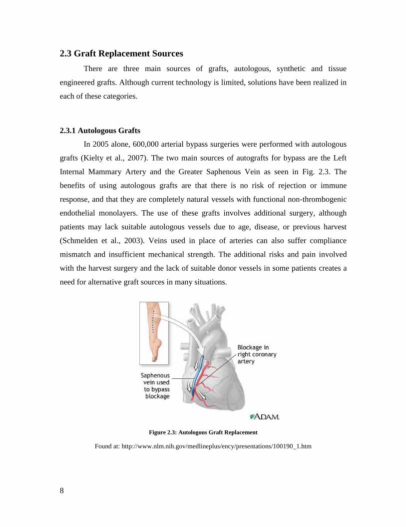
2.3.1 Autologous Grafts
In 2005 alone, 600,000 arterial bypass surgeries were performed with autologous
grafts (Kielty et al., 2007). The two main sources of autografts for bypass are the Left
Internal Mammary Artery and the Greater Saphenous Vein as seen in Fig. 2.3. The
benefits of using autologous grafts are that there is no risk of rejection or immune
response, and that they are completely natural vessels with functional non-thrombogenic
endothelial monolayers. The use of these grafts involves additional surgery, although
patients may lack suitable autologous vessels due to age, disease, or previous harvest
(Schmelden et al., 2003). Veins used in place of arteries can also suffer compliance
mismatch and insufficient mechanical strength. The additional risks and pain involved
with the harvest surgery and the lack of suitable donor vessels in some patients creates a
need for alternative graft sources in many situations.
Figure 2.3: Autologous Graft Replacement
Found at: http://www.nlm.nih.gov/medlineplus/ency/presentations/100190_1.htm

9
2.3.2 Synthetic Grafts
When suitable autologous vessels are unavailable, completely synthetic grafts
have been used, pictured in Fig. 2.4. Dacron and ePTFE are the main materials used in
synthetic vascular grafts today (Ratner et al., 2004). In small diameter applications, these
synthetic grafts are highly susceptible to clotting and failure due to a lack of a conFluent
non-thrombogenic endothelial monolayer. Upon implantation, the luminal surface of the
synthetic graft is coated with plasma proteins, and eventually a platlet-fibrin aggregate
(pseudointima). This is then covered with an endothelial layer, but only in a 10-15 mm
zone from the anastomosis. The pseudointima that is not endotheliazed can be subjected
to SMC migration and proliferation leading to intimal hyperplasia, or trigger clot
formation and thrombosis. Fibrous hyperplasia caused by an over active physiological
repair response at the anastomic site also often leads to failure of the grafts.
Figure 2.4: Synthetic Graft Replacement
Found at: http://www.atsmedical.com/uploadedImages/Public_Site/Products/Mechanical_
Valves/BI1-1_avg.jpg
2.3.3 Tissue Engineered Grafts
The most common tissue engineering approach involves the use of exogenous
scaffolds into which cells are seeded and cultured. These scaffolds provide structural
support and allow for cell growth, migration, differentiation and cellular ECM
production. Ideally, these scaffolds would degrade at the same rate as the natural tissue
would proliferate and synthesize ECM. Tissue engineering scaffolds can be composed of

10
either natural or synthetic materials. An example of a tissue engineered graft is shown
below in Fig. 2.5.
Figure 2.5: Lifeline Graft
Found at: http://cytograft.com/technology.html
2.3.3.1 Synthetic scaffolds
Synthetic scaffolds can be created from a variety of polymers such as polyesters,
polyanhydrides, and polyphosphazenes (Yoon and Fischer, 2006). The initial chemicals
and reactions necessary to synthesize these polymer scaffolds are incompatible with cell
survival. Therefore the cells cannot be incorporated directly into the polymer scaffolds as
they are formed. Instead cells must be seeded into the completed scaffolds posing
difficulties in achieving uniform cell distribution and attachment. The scaffold
degradation rate must be equal to the cellular proliferation rates and ECM synthesis in
order to maintain graft structure and mechanical properties, and to avoid failure.
Polyglycolic acid (PGA) and Polylactic co-glycolic acid (PLGA) are most commonly
used as tissue engineering scaffold but are both resorbed rapidly (Isenberg et.al., 2006).
It has been found that tailoring polymer scaffold degradation rates to correspond with
varying cellular proliferation rates and ECM synthesis, while maintaining
biocompatibility, poses a considerable challenge (Nerem and Ensley, 2004).
Although synthetic scaffolds provide initial mechanical strength and structure,
compliance mismatch with native vessels has proven difficult to overcome (L’Heureux

11
et. al., 2006). This is due to the inability to match the mechanical properties of native
vessels with synthetic vessels, which result in low compliance between the native tissue
and graft. Thrombosis can result when mismatch between the mechanical properties of
the native tissue and replacement occurs. Compliance mismatch quickly leads to the
failure of implanted grafts due to the stresses of repetitive cyclic loading, which occurs
when blood is continuously pumped through the vessel. The compliance of vascular
grafts once the scaffold has resorbed is the result of cell generated ECM (Heydarkhan-
Hagvall et. al., 2006). However, it has been shown that ECM production is inhibited in
cells that are in contact with synthetic polymers (Nerem and Ensley, 2004). This finding
has led many researchers to investigate alternatives to synthetic polymer scaffolds.
2.3.3.2 Natural Scaffolds
Natural protein scaffolds utilize the components of native ECM and create fully
biological grafts. Natural protein scaffolds can be composed of collagen, elastin,
fibronectin, or protein hydrogels (Stegemann et al, 2007). However, these scaffolds do
not provide sufficient initial mechanical strength to support normal hemodynamic loading
(Zhang et al, 2007). To improve mechanical properties and increase collagen fiber
alignment, cross-linking has been increased and mechanical conditioning has been
applied in vivo (Nerem and Ensley, 2004). Additionally, natural protein scaffolds are
often difficult and expensive to manufacture (Stegemann et al, 2007).
Decellularized tissues are also used as scaffolds, composed of natural ECM, and
as such offer improved biocompatibility. Animals can be used as a tissue source with the
benefit of being readily available and inexpensive. The chemical processes through which
the tissues are decellularized however, negatively affect the mechanical properties
(Swartz et al, 2005). Chemical cross-linking is then required in order to attempt to restore
suitable mechanical properties, which have yet to be tested I complex and risky situations
such as a bypass-application (Stegemann et al, 2007).
2.3.3.3 Cell-Derived Vascular Grafts (No Exogenous Scaffolds)
Researchers are developing alternative approaches that avoid the use of
exogenous scaffolds. By creating completely biological vascular grafts without the use of

12
exogenous scaffolds, it is likely that compliance match can be more easily achieved
(Swartz et al, 2005). This approach requires that the cells synthesize their own
ECM/scaffold. ECM production in cells can be stimulated through surface topography,
chemical signaling, and mechanical conditioning (Swartz et al, 2005).
Cell sheets have been cultured and utilized to create layered vascular grafts.
Monolayers of fibroblasts and SMCs have been cultured in medium enriched with
ascorbic acid in order to stimulate production of collagen type I. The resulting vessels
have high burst strengths of 2000 mmHg and perform well in suture pull out tests
(L’Heureux et al, 2006). These collagen-rich cell sheets can be removed from the
culturing surface without damage, which is essential. Multiple sheets are wrapped around
a mandrel in order to form a tubular graft. Such grafts have recently been approved for
use in clinical trials in blood vessel access applications (L’Heureux et al, 2006).
Cytograft Tissue Engineering, in late 2008, reported results from their first
clinical trial using sheet-based tissue engineered vessels (Konig et al., 2008). The multi-
ply graft can be seeded with endothelial cells to produce a completely autologous tissue
engineered blood vessel named LifelineTM
. The cells for these clinical trials were sourced
from patients with end-stage renal disease, lower-limb ischemia, or coronary artary
disease, 25 patients in total. The engineered blood vessels were compared to native
human vessels in patients with advanced cardiovascular disease in burst pressure, fatigue
resistance with static or dynamic loading, suture retention strength, and compliance tests.
This was the first demonstration of completely biological tissue engineered blood vessels
implanted in humans (Konig et al, 2008). The vessels were implanted as either an arterio-
venous shunt for dialysis purposes, or a lower-limb bypass, which have greater failure
rates than upper-body replacements due to increased pressure. The results from this
clinical trial provide benchmarks for future cardiovascular tissue engineering studies
(Konig et al, 2008).
L’Heureux and his research team have been largely responsible for the success of
vascular grafts generated through the utilization of cultured cell sheets. High patency and
anti-thrombogenicity have been achieved in animal and human models with these grafts.
Lengthy production times are required with these techniques however, and greatly hinder
clinical implementation. Additionally, the over expression of collagen necessary to make

13
the grafts easy to handle, results in compliance mismatch and overly stiff grafts (Swartz
et al, 2005).
2.4 Patents
An in-depth patent search was conducted to find completely tissue-engineered
vascular grafts. Although there are similar patents using scaffolds and manipulated
grafts, there is currently only one patent for a completely tissue-engineered vascular graft.
Two patents and one patent application were found through the U.S. Patent and
Trademark Office. The patents and applications were found to be the only ones that
claimed to be able to produce completely scaffold free, cell derived tissue engineered
grafts.
2.4.1 Patent # US 7,112,218 B2
Todd McAllister and Nicolas L’Heureux filed patent# US 7,112,218 B2 on
September 26, 2006. This was for a bioreactor with mechanisms to grow tissue sheets and
a rolling mandrel for the sheets to wrap around. This allows tissue sheets to be grown and
then concentrically wrapped around a mandrel in order to create autologous blood vessels
with little handling as seen in Fig. 2.6. There is a clamp for holding the sheet to the
mandrel while wrapping the tissue. Fibroblasts are isolated from a skin biopsy, and
cultured into a sheet. A supplementary rod with a control blade that rotates toward the
sheet is used in order to separate 1-3 cm of the sheet’s leading edge. This separated
portion is then draped over the rollable mandrel. A magnetic clamp holds the tissue sheet
to the mandrel, and remains in the roll to be taken out later. A Teflon coating over the
mandrel prevents cell adhesion. Once the tubular vessel has matured, the cells are
denatured. A cell sheet of fibroblasts is rolled over the denatured vessel. A suspension of
endothelial cells is then placed in the lumen of the vessel to seed the lining. These vessels
can be directly grafted into the patient or can be further conditioned mechanically with
hemodynamic forces (McAllister et al, 2006).

14
Figure 2.6 Rolling Mandrel (McAllister et al, 2006)
2.4.2 Patent # US 20,060,240,061 A1
Atala et al. of Wake Forest University developed a method utilizing a matrix
seeded with endothelial cells, as stated in application US 20,060,240,061 A1. A
biocompatible matrix is seeded with endothelial cells and there is a chamber that
preconditions the matrix by moving biological fluid through the inner surface. This is a
continuous flow that can be adjusted to control shear stresses in the vessel wall. Pulse
rates and pressures are also adjusted to condition the tubes. The exterior can be pre-
conditioned with this device by filling the preconditioning chamber with biological fluid.
Therapeutic agents such as heparin can also be incorporated into the scaffolds. The
scaffolds were created using electrospun fibers to allow greater flexibility and the
creation of custom shapes. Teflon was also used in order to reduce cell adherence to the
mold (Atala et al, 2006).
2.4.3 Patent Application # US 20,070,128,171
Another patent for tissue engineered blood vessels was completed by Tranquillo,
Fig. 2.7, depicts the proposed blood vessel. Tranquillo developed a method to create
engineered blood vessels which include an intimal layer surrounded by a smooth muscle
media layer which are constructed around a tubular support. A matrix of endothelial cells

15
and smooth muscle cells form a bi-layer. This bi-layer forms a tubular structure around a
support which is permeable to attractant factors. The application states that the formation
of endothelial intimal layers should be surrounded by a smooth muscle medial layer,
following the protocol that was conducted.
Figure 2.7: Drawing of Tranquillo's Layered Tissue Engineered Blood Vessel
2.5 Gaps in Current Technology
As previously discussed, current technology is lacking a suitable small diameter
blood vessel replacement. The primary source for small diameter graft replacements is
the autologous vessel, which requires a second surgery. The second surgery increases the
risk of infection, pain from the operation and lengthens surgery time. Out of the 785,000
Americans who have a myocardial infarction, 470,000 are estimated to have recurrent
attacks. These patients have a continued heart disease, as well as previously harvested
vessels, making the resources for second surgeries limited (Lloyd-Jones et al, 2009).
Coronary heart disease is estimated to cost $165.4 billion annually through direct and
indirect costs. Tissue engineered blood vessels for coronary bypass would greatly impact
the state of the art and is only one possible application for these grafts. Implanting grafts
as a dialysis fistula and replacing any vessel in the body, especially lower limb vessels,
are other applications of a completely tissue engineered vessel.
The Cytograft technology is innovative and shows great promise for tissue
engineering grafts. The task of completely cell-derived grafts is achieved, but the
resulting grafts take about 6 months to produce, a very impractical timeline. Additionally,
the clinical data was recently released, showing the results of several mechanical tests.

16
The Lifeline vessel replacement was compared to internal mammary arteries, and the
results were drastically different in cases such as burst pressure and compliance. A native
internal mammary artery has a burst pressure of 1599±877 mmHg while the Cytograft
vessel ranged from 3399-3523 mmHg, nearly triple. For compliance, the native vessel
was 11.5%100/mmHg while Cytograft was 3.4%/100mmHg, showing that the engineered
tissue was much stiffer (Konig et al, 2008). While these vessels show promise and
successful in vivo testing, there are still issues with mechanical properties that need to be
addressed during culture.
Synthetic vessels work well in large diameter vessel replacements, such as aortic
aneurysms, but can cause clots in small diameter applications. The immune response
elicited from implanting a polymer and the lack of anti-thrombogenic endothelial cells
make these ineffective in bypassing surgeries. The mechanical properties of synthetic
grafts are also different enough to cause problems. Using tissue-engineered vessels can
eliminate the immune response as well as eventually lead to closer mechanical properties
to native tissue.
The bioreactor design itself is a great opportunity to address two large problems:
mechanical properties by having cells self-assemble into the vessel geometry and cut
down the growth time of tissue-engineered vessels. By using a cylindrical mandrel and a
method having cells culture in the natural assembly of blood vessels, the current
problems related to tissue engineered grafts may be eliminated. Cell alignment is crucial
to the strength and properties of the vessels and the assembly process can influence the
cell growth direction. Also, a bioreactor that facilitates self-assembly will reduce
manipulation and culture time for layers to fuse after growing in sheets. The idea that
cells can be put into a bioreactor and after a culture period, a blood vessel may be
removed is the ultimate goal of this project. The approach of this project is to create a
whole system that will enable sterile cell culture and growth of tissue engineered vessels,
eliminating production time and potential for user error or concern.
17
3. 0 Project Strategy
The design of a bioreactor to facilitate cell-derived vascular grafts was motivated
by the need for small diameter vascular replacements. Throughout the design process the
client’s needs were assessed in order to direct the development of the project. In order to
meet the client’s expectations, interviews were conducted resulting in a client statement.
From here, design objectives, functions, specifications, and constraints were established.
Various design methods were utilized to further clarify the goals of the project. These
methods included pairwise comparison charts, objective trees, and functions-means trees
were used to guide the development of the design.
3.1 Initial Client Statement
Weekly interviews were conducted with our client and advisor, Dr. Marsha Rolle.
In these meetings, the need for small diameter vascular replacements and the problems
associated with current vascular graft designs were presented and discussed. The client’s
initial desires for the design were outlined in the initial client statement:
The goal of this project is to design a bioreactor to 1)
generate totally biological vascular grafts by cellular self
assembly into tubular structures (in the absence of
exogenous scaffolds and cell sheets) and 2) support sterile
culture and conditioning of the resulting vascular grafts.
The ultimate goal of the project is to create a device that
will reproducibly generate tissue engineered blood vessels
with physiological and mechanical properties suitable for
transplantation.
The above client statement was expanded and revised as interviews continued and
as sufficient background research was conducted.

18
3.2 Objectives & Constraints
Key goals of the project were determined from the revised client statement and
expanded into a complete list of objectives and constraints. The list was split into
objectives for the bioreactor design and objectives for the vascular grafts. Pairwise
comparison charts (located in Appendix A) were used to weigh the importance of each
objective and constraint. The objectives were broken further into sub-objectives and both
were compiled in an objectives tree shown in Fig. 3.1 and 3.2.
3.2.1 Bioreactor
After an in-depth discussion on what features, attributes and functions the
bioreactor should satisfy, objectives and constraints for the bioreactor were determined.
In order to fulfill the client statement, the bioreactor was designed to produce tissue in a
cylindrical form so that no tissue manipulation is required to produce a graft. Not only
should this bioreactor produce grafts quickly, it should also be easy to use, safe and
provide a continuous nutrient delivery. Finally, the bioreactor should be able to produce
more than one tissue tube at a time and should be inexpensive to produce and grow the
grafts. Objectives of the bioreactor are shown in Fig. 3.1.
Figure 3.1: Bioreactor Objectives
There were also numerous constraints that needed to be taken into consideration
when designing the bioreactor. Time and budget were driving constraints; the project
needed to be completed with a budget of $624.00 and by April 30th
, 2009. The facility
used to create the bioreactor was also a constraint because the project was completed in
Bioreactor
Easy to use
Minimal manual input
Outputs tubular
construct
Mutiple cultures
Continuous nutrient delivery
Fast graft generation
Increased cell proliferation
rates
Low cost Safe for user

19
an assigned lab area in Salisbury Laboratories at Worcester Polytechnic Institute. Space
was limited and the bioreactor needed to fit within the allotted space in the incubator.
3.2.2 Vascular Grafts
In order to design and build a bioreactor, it was also important to keep in mind the
desired objectives for the vascular grafts that would be produced by the bioreactor. The
bioreactor should be able to produce vascular grafts in a manner that is reproducible, so
that not only each graft is the same, but also so that the bioreactor produces the same cell
derived graft each time it is used. The design should also incorporate a way to influence
the grafts to self generate Extracellular Matrix (ECM). When the bioreactor has produced
vascular grafts, these grafts should also be suturable, easy to handle and should be able to
withstand the pressures of a natural tissue which is around 1599 ± 877 mmHg (Konig et
al, 2008).
Figure 3.2: Vascular Graft Objectives
Vascular grafts
Self generated ECM
Self assembly
Fast growth rates
Suturable Easy to handleAppropriate
burst pressures
Reproducible
Minimal manual input
Grafts of same dimensions
Biocompatible

20
3.3 Revised Client Statement
A revised client statement was developed through determining the objectives and
constraints of the project. The revised client statement is as follows:
The goal of this project is to develop a method to quickly
generate multiple vascular grafts through the design of a
novel bioreactor. The method and design should stimulate
self assembly of cells introduced to the bioreactor, without
the use of exogenous scaffolds. The design should produce
reproducible tubular grafts that have self generated
extracellular matrix. Additionally, the necessity for graft
manipulation should be minimized so that the vessels are
produced quickly and easily. The completely biological
vascular grafts should be approximately 2 mm in diameter,
5 cm in length, and 250 µm in wall thickness. The resulting
grafts should be suitable for transplantation: sutureable,
easy for surgeons to handle, strong enough to withstand
pulsatile flow and biocompatible with the recipient.
3.4 Needs Analysis
In order to determine which objectives were most important, a pairwise
comparison was used and can be found in Appendix A. Scores were given based on
conversations with the client and calculated appropriately. Needs and wants of the design
were narrowed down based on scoring. This weighted objective tree for the objectives of
the bioreactor is shown in Fig. 3.3. The safety objective was eliminated from the tree as it
is always considered throughout the process and was deemed the most important by the
client. Through additional conversations with the client it was determined that developing
and validating the bioreactor design was the main objective of the project, which was
continued throughout the remaining portion of the project.

21
Figure 3.3: Weighted Objective Tree based on needs analysis
3.5 Bioreactor Functions
In order to meet the objectives of the bioreactor, desired functions of the
bioreactor were split into three main categories. The categories and the functions of the
bioreactor are listed in Table 3.1. The design of the bioreactor consisted of determining
the best structure to assemble the cells, the method to assemble and culture cells and the
housing to culture and monitor tissue.
Table 3.1: Bioreactor Functions
Functions of Bioreactor
Structure to Assemble the Cells
Creates/Supports tubular construct
Allow removal of intact tubular
construct
Method to Assemble and Culture Cells
Facilitate cell seeding
Promote cellular growth
Promote cell adhesion
Housing to Culture and Monitor Tissue
Allow nutrient diffusion/ gas exchange
Allow for visualization of fibers
Housing for fibers
Fixation of Fibers
Vacuum adheres cells to mandrel
Closed off housing
Fibers are easily removed
Bioreactor Design
Generate tubular construct
26 %
Fast graft generation
18%
Continuous nutrient delivery
10%
Easy to use
15 %
Multiple cultures
0%
Low cost
0%

22
3.6 Project Approach
Once the functions of the bioreactor were clearly established, the design of the
bioreactor began in three distinct categories to be designed and verified. These three
design categories were examined and analyzed in parallel to determine the optimal means
to create the bioreactor as seen in the morphological chart in Appendix B and design
matrixes in Appendix C. As pictured in Fig. 3.4, the bioreactor functions were split up
into three main categories which were; structure to assemble cells, method to assemble
and culture cells and a housing to culture and monitor tissue. Each of these three
categories were investigated in Chapter 4 and later verified in Chapter 5.
Figure 3.4: Three Function Groups of Bioreactor

23
4.0 Alternative Designs
Once the project objectives were weighted by importance in designing the
bioreactor, conceptual designs were generated. Through initial brainstorming, functions
were developed and it was decided that cells would need a surface to adhere to in order to
meet confluence and create a tubular structure. With the functions in mind, different
designs were investigated to meet the functions and objectives of the bioreactor.
Additional components were added to a traditional bioreactor to promote cell growth and
cell seeding. A custom cartridge in which to culture the vascular grafts would be
necessary. The compiled functions helped in creating an overall schematic of how the
bioreactor would be assembled, which is shown in Fig. 4.1.
Figure 4.1: Bioreactor Schematic
The conceptual designs were chosen with the functions in mind. Controlling the
cells as they grow eliminated the step of manually rolling sheets of tissues into tubes,
which is currently a critical step in tissue engineered grafts
4. 1 Structure to Assemble Cells
The first function category that was investigated was the structure to assemble the
cells on, the schematic depicted in Fig. 4.2. The options were split up into a group of

24
cylindrical mandrels upon which to culture the cells a mechanical mandrel idea, which
would allow for flat cell growth and a porous mandrel idea which would allow for
nutrient diffusion.
Figure 4.2: Structure to Assemble Cells
4.1.1 Mandrel Designs
In order to culture cells directly into tubular structures, four main design
categories were developed. These four design categories all involved the use of tubular
forms or mandrels upon which the cells would be directly cultured and self assembled
into tubular vessels. The first design category utilizes a cylindrical mandrel the size of the
inside diameter of the required vessel and can be seen in Fig. 4.3. The cells could be
cultured into a vascular graft around the outer surface of the mandrel.

25
Figure 4.3: Mandrel Designs
The second category would utilize a tubular dye. Cells could be cultured on the
inner surface of the dye, as seen in the Fig. 4.3. The dye would have an inside diameter
equal in size to the outside diameter of the required vascular graft.
The third design, as pictured in Fig. 4.3, would allow for cell culture around an
outer diameter, equal in size to the desired inner diameter of the vascular graft. One
option for a hollow mandrel that was investigated in depth was hollow fibers, which are
used in filtration cartridges and hollow fiber bioreactors. Hollow fiber bioreactors, as
seen in Fig. 4.4, create an artificial capillary system in a cartridge so that higher cell
densities and proliferation rates can be achieved as compared to standard flask or plate
culture techniques. Fibercell Systems Inc. produces a hollow fiber bioreactor with fibers
that are 1.3 mm in outside diameter.

26
Figure 4.4: FiberCell Cartridge
Media circulating through the porous hollow fibers delivers glucose, oxygen, and
nutrients to the cells, and at the same time carries metabolic waste products as seen in
Fig. 4.5. Media flow through the porous hollow fibers also ensures that cells attached to
the mandrel receive the same nutrient diffusion from inside and outside the fibers as the
cells interacting with the media inside the main cartridge.
Figure 4.5: Oxygen, Nutrient and Waste Flow through Fibers

27
The fourth and final design category, as seen in Fig. 4.3, would utilize a mold in
which the vascular graft would be cultured. The negative space created by the mold
would be the size of the required vascular graft. This mold would also control the wall
thickness of the graft by establishing both the inside and outside diameters. The negative
space mold approach constrains the cells within a space such that the cells needn’t
necessarily attach to the surface. This design was similar to a conventional negative space
mold. The challenge in this design was to keep the cells dispersed throughout the mold,
as the force of gravity would naturally draw them all to the bottom. By rotating and or
vibrating the mold in various directions it could be possible to keep a media and cell
solution evenly distributed throughout the mold until the cells proliferate sufficiently to
form a unified tubular construct.
These approaches require some method of maintaining the cells on the surface of
the die or mandrel in opposition to the force of gravity. Until the cells attach sufficiently
to the surface, or confluence is reached and cell to cell attachment is sufficient, gravity
will prevent cells from maintaining contact with the surface of the die or mandrel. This
problem would not be encountered in cell sheet culture as gravity keeps the cells arranged
on the flat surface upon which the sheets are cultured.
4.1.2 Mechanical Mandrel
As an alternative to using a mandrel that is initially tubular, the possibility of
using a structure that was initially flat was also considered. This would allow the cells to
be easily seeded and cultured into sheets, since cells are commonly grown on a flat dish.
Once the cells reached confluence or sufficient cellular attachment to the structures
surface was achieved, the structure could roll up into either a tubular die or mandrel. A
close view of the flat roll-able mandrel can be seen in Fig. 4.6.

28
Figure 4.6: Flat Mandrel before Rolling
The cells could then be further cultured into the final tubular construct, as seen in
Fig. 4.7, by allowing the cells to proliferate until the seam between the two ends of the
sheet were fused and the appropriate wall thickness was achieved. These mechanical
mandrels or dyes would be made of a flexible culture surface or membrane, attached to a
mechanical, segmented structure.
Figure 4.7: Mechanical Mandrel Rolled
The mechanical mandrels or dies investigated fell into two categories. The first
involved the use of multi-component mechanical assemblies that could easily convert
from flat to tubular structures. These mechanical dies or mandrels would have to create
inside or outside graft diameters of only a few millimeters. The second category of
mechanical die or mandrel involved the use a shape memory alloy such as nitinol. This
could eliminate the need for complex multi component structures, since these shape
memory alloys can convert from one shape to another based on temperature changes or

29
other external stimuli. A flat membrane could be lined with simple nitinol bands that
could alternate between flat bands and round hoops, thus creating a construct that
transforms from a flat into a tubular structure when the appropriate external stimulus was
applied.
4.2 Method to Assemble and Culture Cells
The second design function that was investigated was the method to assemble and
culture the cells on. The selection of the method was also determined by the structure to
assemble the cells. Four methods to seed the cells onto a mandrel were investigated.
Static seeding, a method to manually rotate the cartridge, and an automated rotation
system and a pump/vacuum system led to the final decision, which was determined
through design verification. This design function is highlighted from the overall
schematic in Fig. 4.8.
Figure 4.8: Method to Assemble and Culture Cells
4.2.1 Static Seeding
The simplest seeding method would be a static seeding method in which the cells
would be seeded into the chosen housing of the bioreactor. In the case that a mechanical
mandrel was used, static seeding would be an option. Static seeding is a common method
in which cells are simply placed in a flask and allowed to grow into cell sheets.

30
4.2.2 Manual Rotation
Avoiding the use of cell sheets and mechanical mandrels would be achieved by
allowing the cells to attach in series to a slowly rotating mandrel or dye surface.
Sufficient attachment strength would need to be achieved before the surface was rotated
such that gravity opposes the cell to surface attachment. This would have required a very
slow rate of rotation and perhaps an equally slow introduction of cell suspension to
prevent cell aggregates from forming instead of cell to surface binding.
4.2.3 Automated Rotation System
An automated rotation system would have eliminated the need to manual rotate
the cells and could be controlled. This would have been able to eliminate the uncertainty
involved in manually rotating cells for a specified time and would also eliminate the
manual work required, better meeting the objectives of the bioreactor.
4.2.4 Pump/Vacuum System
Another possible method for maintaining the cells on the surface of a mandrel,
involved the creation of a vacuum at the surface resulting from an inward flow of media.
This flow would maintain the cells on the surface until they attach to the surface or
proliferate sufficiently to aggregate and provide their own mechanical support, Fig. 4.9.
The use of a porous construct would be required so that media could be drawn through
the surface to create a vacuum. Media flow could also provide nutrient and gas exchange
and thus provide biological support as well as mechanical support.

31
Figure 4.9: Cell Attachment to Surface
4.3 Housing to Culture and Monitor Tissue
The third function of the bioreactor was an essential step in developing bringing
each of the components together. It was necessary to take into account each of the
objectives, constraints and functions in order to produce this central piece of the system.
Design alternatives for the cartridge were generated using a morphological chart located
in Appendix B and qualified using a decision matrix found in Appendix C. The housing
to culture and monitor tissue, Fig 4.10, was designed to allow constructs to be easily
removed and installed, cells to be seeded directly into the cartridge and to accommodate
multiple cultures. Additionally the design was expanded to allow for housing, fixation,
and visualization of the cultures and facilitation of cell dispersion during seeding.
Additionally the design of the cartridge should incorporate a material that should inhibit
cell adherence.
32
Figure 4.10: Housing to Culture and Monitor Tissue
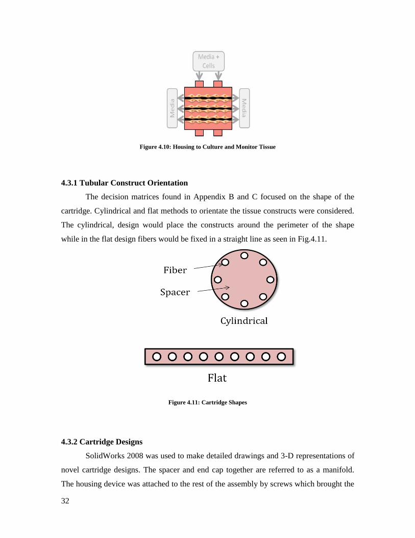
4.3.1 Tubular Construct Orientation
The decision matrices found in Appendix B and C focused on the shape of the
cartridge. Cylindrical and flat methods to orientate the tissue constructs were considered.
The cylindrical, design would place the constructs around the perimeter of the shape
while in the flat design fibers would be fixed in a straight line as seen in Fig.4.11.
Figure 4.11: Cartridge Shapes
4.3.2 Cartridge Designs
SolidWorks 2008 was used to make detailed drawings and 3-D representations of
novel cartridge designs. The spacer and end cap together are referred to as a manifold.
The housing device was attached to the rest of the assembly by screws which brought the

33
four pieces together to form the cartridge housing. The pieces were designed so that they
could be screwed together, allowing for access to the constructs. The cartridge design
shown in Fig. 4.12 incorporates the cylindrical formation of the grafts where the cartridge
design in Fig. 4.13 incorporates the flat orientation of constructs.
Figure 4.12: Cylindrical Cartridge Design
Figure 4.13: Flat Cartridge Design

34
5.0 Design Verification
In order to verify the design of the bioreactor, the three main functions were
tested in parallel. The final design aspects that were chosen were the porous hollow fibers
to be used as the support structure to grow the cells on. The vacuum system was chosen
as the seeding method and the flat cartridge was chosen as the housing to monitor and
culture the tissue. These aspects were chosen based on the decision matrices in Appendix
C and conversations with the client. The hollow fiber mandrels allowed for vacuum
seeding and artificial cell culture, satisfying two functions of the bioreactor. Therefore,
the housing design was based off the size of the fibers as seen in Fig. 4.13. and 5.1.
Figure 5.1: SolidWorks Cartridge
The support structure to assemble the cells was tested by verifying that the porous
hollow fibers (polysulfone+ FiberCell) could support cell growth and to determine a

35
method to visualize cell growth without removal from the bioreactor’s cartridge. The cell
assembly and culture methods were also tested and analyzed using Fluent computational
fluid dynamics software and pump testing. The housing to culture and monitor the tissue
was also tested using Fluent and additional visualization testing.
5.1 Verification of Support Structure
Assuming the bioreactor would be used for research purposes, growth within the
bioreactor needed to be assessed without compromising the tissue. When observing the
fibers using a compound microscope the fibers appear black. Therefore it was essential to
develop a method to distinguish the polysulfone+ fibers, shown in Fig 5.2, from the HDF
cells in order to assess cell attachment and growth. Additionally, the compatibility of
polysulfone+ fibers with cell growth was observed. The two methods used to verify the
support structures, the hanging drop and the v-well, which are explained in more detail in
Section 5.1.1 and 5.1.2.
Figure 5.2: Magnified Fibers (Hydrated and Dehydrated)

36
Human Dermal Fibroblasts (HDFs) were cultured starting at passage 12. Cells
were observed approximately every 24hrs, fed approximately every 48 hrs, and passaged
when observed to be 80-100% confluent. Cells were cultured using DMEM which
contained approximately 10% Fetal Bovine Serum (FBS) and approximately 1% Pen-
Strep. Before utilization in experiments, the number of viable cells was measured using
Trypan Blue in order to make the specified cell concentration for experimentation.
Trypan Blue stains dead or dying cells while viable cells are not dyed. A 1:1 solution of
Trypan Blue and cell solution (40µL each) was made and micropipeted into a
hemocytometer used to count the cells.
In order to incorporate the polysulfone+ fibers in tests and the bioreactor design
they first needed to be removed from the FiberCell cartridge which contained 20, 10cm
long fibers. This process was carried out in a sterile environment and with sterile tools in
order to ensure that the fibers would not be contaminated. All materials used to open the
cartridge were sterilized using an autoclave for 15 minutes at 121oC and all procedures
were performed in a fume hood, Fig. 5.3.
.
Figure 5.3: Materials Used to Open FiberCell Cartridge
A disposable sterilized towel was placed on the work surface of the fume hood to
decrease the risk of contamination. A saw was used to remove the end-caps of the
FiberCell cartridge and sterile surgical scissors were used to separate the polysulfone+

37
fibers which were embedded in polyurethane. Forceps were used to place the fibers on
the sterilized towel so that they could be cut into the specified lengths. The fibers were
cut using a razor into ten 6cm fibers and ten 4cm fibers. The 4cm fibers were then cut in
half resulting in twenty 2cm fibers. The fibers were placed using forceps in 15mL sterile
centrifuge tubes in order to store them without risk of contamination. The fibers were
separated into six different centrifuge tubes so that there were 5 fibers in each tube in
order to further prevent contamination.
It was necessary to precondition the polysulfone+ fibers before they could be
successfully used in cell culture. The preconditioning was in accordance with the
protocols outlined in the FiberCell guide (Hollow Fiber Bioreactor User’s Manual, 2008)
Only the 2cm fibers were statically preconditioned while the 6 cm fibers were kept for
use in the completed bioreactor design. The fibers were soaked in ethanol, phosphate
buffered saline (PBS), cell culture media according to the procedures outlined in Sections
5.1.1 and 5.1.2.
5.1.1 Verification Using Hanging Drop Method
The hanging drop method is a technique utilized to promote cell adhesion to a
tubular construct using the forces of gravity. This technique was used to determine the
methods that would allow the best visualization of HDF attachment, confluence,
proliferation, and viability on the polysulphone+ mandrel. Polydimethylsiloxane (PDMS)
was mixed with 10% curing agent and poured into a cylindrical mold. A small piece of
silicone tubing (about 1.3mm OD and 2cm length) was placed on the PDMS to form a
grove where the polysulphone+ fibers would sit. The PDMS filled mold was placed in an
oven at 80oC for 45 minutes. The cured PDMS rings were removed from the mold and
sterilized using an autoclave. A 2cm polysulphone+ fiber was placed in the grove and
fixed using sterile silicon glue.
The glue was allowed to set for 30 minutes. The PDMS rings, with attached fibers
facing up, were fixed using silicon glue in the middle of three six well plates, one per
well until a total of 16 wells contained the PDMS ring and attached fiber. This set-up is
shown in Fig. 5.4.
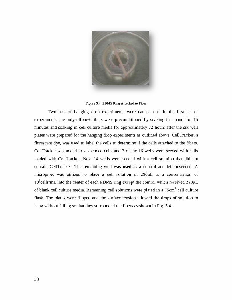
38
Figure 5.4: PDMS Ring Attached to Fiber
Two sets of hanging drop experiments were carried out. In the first set of
experiments, the polysulfone+ fibers were preconditioned by soaking in ethanol for 15
minutes and soaking in cell culture media for approximately 72 hours after the six well
plates were prepared for the hanging drop experiments as outlined above. CellTracker, a
florescent dye, was used to label the cells to determine if the cells attached to the fibers.
CellTracker was added to suspended cells and 3 of the 16 wells were seeded with cells
loaded with CellTracker. Next 14 wells were seeded with a cell solution that did not
contain CellTracker. The remaining well was used as a control and left unseeded. A
micropipet was utilized to place a cell solution of 280μL at a concentration of
106cells/mL into the center of each PDMS ring except the control which received 280μL
of blank cell culture media. Remaining cell solutions were plated in a 75cm3 cell culture
flask. The plates were flipped and the surface tension allowed the drops of solution to
hang without falling so that they surrounded the fibers as shown in Fig. 5.4.

39
Figure 5.5: Hanging Drop Plates
At this point, the plates were allowed to incubate for 1hr. After cell attachment the
plates were flipped back to their normal orientation. The remaining solution was
aspirated and 6mL of fresh media was added to each well as shown in Fig. 5.6.

40
Figure 5.6: Media in a Hanging Drop Well
The wells that contained cells with CellTracker solution were viewed using a
florescent microscope after the 1 hr seeding period. The observed fibers were fluorescing
but the control also fluoresced. The plated cells that contained CellTracker were viewed
using the fluorescent microscope and the cells fluoresced much brighter than the fibers.
At this point it was determined that cells had not attached onto any of the fibers that were
seeded with the CellTracker cell solution. After 3 days CellTracker solution was added to
3 wells seeded normally (not loaded with CellTracker). Once again no observable
difference could be determined when the seeded wells were compared to the controls.
Once again it was determined that no cells had attached to these fibers. Although the
protocol developed for this experiment outlined instructions to add CellTracker to 3 wells
every 3 days, the experiment was stopped at this point since no cell attached was
observed.
The cells plated with CellTracker were observed over a 48 hour period to
determine the effects of CellTracker on cell viability. It was observed that the cells
loaded with CellTracker were not as healthy as unmodified cells. From these
observations it was determined that loading the cells with CellTracker before cell seeding
could be affecting cell attachment. The protocol for the second hanging drop experiment
was modified based on the results of the first experiment. Furthermore, on second
examination of the FiberCell Bioreactor guide, it was determined that in order for cell

41
attachment to occur on the polysulfone+ fiber, they must also be preconditioned with
PBS.
A second hanging drop experiment was therefore set up with an adapted protocol.
For this experiment the fibers were preconditioned by soaking in ethanol for 15 minutes,
soaking in PBS twice for 5 minutes each, and finally soaking in cell culture media for
approximately 72hrs. For this experiment the cell culture media was changed every 24hrs
during that portion of the preconditioning. No cells were seeded with CellTracker
however CellTracker was planned to be added to 3 wells, 3 days after seeding the fiber.
One day after cell seeding, fibers were viewed using a stereomicroscope and compared to
the control which had no cells added to determine if cells had attached to the fibers. At
this point the experiment looked promising but it could not be definitively determined
that cells had attached to the fiber. Two days after cell seeding the plates were observed
and certain wells were found to be contaminated. Therefore the plates were bleached and
disposed of.
At this point the team determined that a method with fewer variables and less risk
of contamination should be implemented in order to verify the support structure chosen
for the bioreactor design. It was determined that the hanging drop method could not
generate reproducible results since it relied heavily on user manipulation. This extensive
manipulation also increased the risk of contamination. Fig. 5.7 shows the inconsistencies
of the hanging drop method.
Figure 5.7: Inconsistency of Method
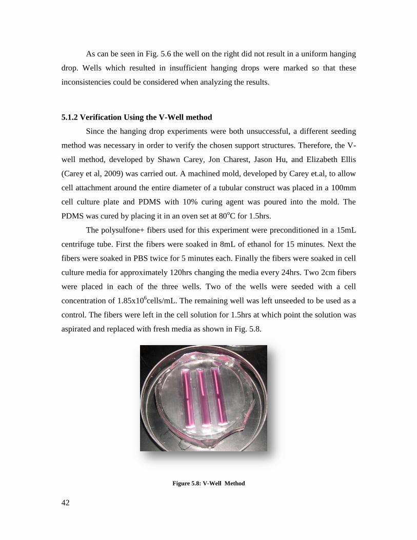
42
As can be seen in Fig. 5.6 the well on the right did not result in a uniform hanging
drop. Wells which resulted in insufficient hanging drops were marked so that these
inconsistencies could be considered when analyzing the results.
5.1.2 Verification Using the V-Well method
Since the hanging drop experiments were both unsuccessful, a different seeding
method was necessary in order to verify the chosen support structures. Therefore, the V-
well method, developed by Shawn Carey, Jon Charest, Jason Hu, and Elizabeth Ellis
(Carey et al, 2009) was carried out. A machined mold, developed by Carey et.al, to allow
cell attachment around the entire diameter of a tubular construct was placed in a 100mm
cell culture plate and PDMS with 10% curing agent was poured into the mold. The
PDMS was cured by placing it in an oven set at 80oC for 1.5hrs.
The polysulfone+ fibers used for this experiment were preconditioned in a 15mL
centrifuge tube. First the fibers were soaked in 8mL of ethanol for 15 minutes. Next the
fibers were soaked in PBS twice for 5 minutes each. Finally the fibers were soaked in cell
culture media for approximately 120hrs changing the media every 24hrs. Two 2cm fibers
were placed in each of the three wells. Two of the wells were seeded with a cell
concentration of 1.85x10⁶cells/mL. The remaining well was left unseeded to be used as a
control. The fibers were left in the cell solution for 1.5hrs at which point the solution was
aspirated and replaced with fresh media as shown in Fig. 5.8.
Figure 5.8: V-Well Method

43
After three days, a 5µM concentration of CellTracker was added to each well. The
cells were then observed using a fluorescence microscope. As observed during the
hanging drop experiments, it was difficult to differentiate the fluorescence of the cells
from that of the fiber. Additionally, it was difficult to observe the fiber while in the V-
wells and therefore the fibers were sacrificed from further experimentation by removing
the cover of the plate and placing one seeded fiber and one control fiber in a 5mm cell
culture flask filled with 6mL of cell culture media. Once again the fibers were observed
using the fluorescence microscope and compared. Fig. 5.9 shows the unseeded (left) and
seeded (right) fibers.
Figure 5.9: Unseeded and Seeded Cell Tracker Fibers
Although the seeded fiber (right) seems slightly brighter and thicker than the
unseeded fiber (left), this observation cannot be definitively quantified. The media in the
wells was then aspirated and the fibers were trypsinized and Trypan Blue dye was used in
conjunction with a hemocytometer in order to determine a cell count if any. From the
cell count it was determined that there was an average of 40,000 cells per fiber
confirming that cells had in fact attached to the fibers. From these results it was
determined that a fluorescent dye would not be sufficient means of visualizing cell
attachment or growth on the polysulfone+ fibers.

44
5.2 Verification of Cell Assembly and Culture Methods
The cell assembly and culture methods were verified using Fluent and other
testing methods explained in this section. In order to verify this aspect of the bioreactor,
the longitudinal flow, used for dynamic cell culture, and the vacuum force, used for cell
seeding and assembly, were analyzed.
First the longitudinal flow field used for cell culturing was verified. The flow field
of the cartridge was modeled in 2D using Fluent as shown in Fig. 5.10. As expected, the
velocities greatly increase when entering the fibers because of the drastic change in area.
Therefore it is necessary to determine an appropriate pump setting (inlet velocity) which
will not disturb the growth of tissue.
Figure 5.10: Fluent 2-D
Accordingly, this model allows a user to manipulate the inlet velocities in order to
determine their respective fiber velocities so that an appropriate pump setting can be
chosen. The pump flow rate was also determined based on the FiberCell manual which
suggests flow rates of 1-4 ml/min per fiber during cell culture. The cartridge design
proposed utilizes 5 fibers, so flow rates of 5-20 ml/min would be required to facilitate cell

45
culture in a single cartridge. Therefore this range of flow rates was tested using Fig. 5.10
above to determine the range of fiber velocities this would create.
The Fisher Scientific variable flow peristaltic pump model number 3389 selected
for use in the bioreactor can produce flow rates of 4.0-600 ml/min. Flow tests using water
were performed to verify the pump output and the actual range of flow rates achieved
through 4 feet of 3/16th
inch silicon tubing were 2-480 ml/min. The 4 feet of tubing was
used to approximate the resistance of the entire bioreactor. Since each cartridge would
require 5-20 ml/min during culture, the chosen pump has the additional capacity to
supply several cartridges at once, and it could also supply cartridge designs with greater
numbers of fibers.
The vacuum force through the wall of the fibers, used for cell seeding and
assembly, was also verified using Fluent. Fig. 5.11 represents the flow around each fiber
when the vacuum force is applied. The inlet velocity was set to 5x10⁻⁶
m/s and there was
a negative pressure in the fibers of 5mmHg representing the vacuum force. For this
model the inlets represent the access points where the cell solution would be injected for
cell seeding. As expected the two ports as inlets on either side have the fastest velocity in
comparison to the rest of the velocity vectors.
Figure 5.11: Flow Around Each Fiber
1 2 3 4 5

46
Figs. 5.12 and 5.13 depict the portion of the fibers which are directly under the
inlet points (fibers labeled 1 and 5) Close to the inlet, there is a clear inequality of
velocities circumferentially. However this 2D representation does not show the flow over
the length of the fiber and therefore this extreme difference (approximately 6.8 x10⁻⁶
to
1.1 x10⁻⁶
) would not be experienced by the whole fiber. Fig. 5.12 and 5.13, depict fibers 1
and 5, shows some turbulence around the circular mandrel however when considering the
magnitude of the velocities the turbulence in negligible.
Figure 5.12: Fiber 1
Figure 5.13: Fiber 5
Fig. 5.14, fibers 2 and 4, shows velocities which approach more circumferential
symmetry. The inner side of the fiber, that which is opposite of the inlets, once again has
slower velocities, but the range of magnitudes is much smaller, approximately 3x10⁻⁶
to
0.5x10⁻⁶
. The inlet flow is still influencing the overall unequal velocities, but the flow is
slow enough that there is no turbulence around the cylindrical mandrel.

47
Figure 5.14: Fibers 2 and 4
Finally, Fig. 5.15 showed the center fiber, fiber 3. Since it is located in the center
of the cartridge, the flows coming in from the ports are symmetrical on both sides,
allowing for the uniform velocities seen below.
Figure 5.15: Fiber 3
Fig. 5.15, above, depicted the ideal scenario, that cells would be drawn uniformly
around the circumference. However, because the pores allow for the media to pass
through, but not cells, the imbalances would fix themselves. Cells are pulled to the
mandrel, and the suction through the pores initially holds the cells in place. This action
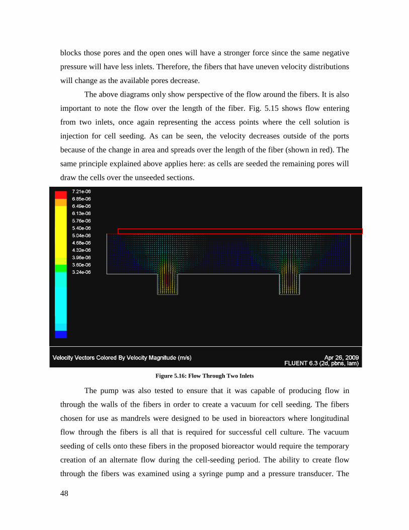
48
blocks those pores and the open ones will have a stronger force since the same negative
pressure will have less inlets. Therefore, the fibers that have uneven velocity distributions
will change as the available pores decrease.
The above diagrams only show perspective of the flow around the fibers. It is also
important to note the flow over the length of the fiber. Fig. 5.15 shows flow entering
from two inlets, once again representing the access points where the cell solution is
injection for cell seeding. As can be seen, the velocity decreases outside of the ports
because of the change in area and spreads over the length of the fiber (shown in red). The
same principle explained above applies here: as cells are seeded the remaining pores will
draw the cells over the unseeded sections.
Figure 5.16: Flow Through Two Inlets
The pump was also tested to ensure that it was capable of producing flow in
through the walls of the fibers in order to create a vacuum for cell seeding. The fibers
chosen for use as mandrels were designed to be used in bioreactors where longitudinal
flow through the fibers is all that is required for successful cell culture. The vacuum
seeding of cells onto these fibers in the proposed bioreactor would require the temporary
creation of an alternate flow during the cell-seeding period. The ability to create flow
through the fibers was examined using a syringe pump and a pressure transducer. The

49
original Fibercell cartridge was connected to the syringe pump and a pressure transducer
so that the pressures required to achieve flow through the walls of the fibers could be
recorded. Flow rates of from 0.01-4.0 ml/min were achieved through each 5 cm of fiber
with pressures of less than 5mm mercury. The actual flow rates used for vacuum seeding
would ultimately be determined experimentally and through modeling of the flow and
forces created at the surface of the fibers.
5.3 Verification of Housing to Culture and Monitor Cells
The housing to culture and monitor the cells was verified using Fluent and
visualization testing. First Fluent was used to verify that the cartridge design allowed for
uniform flow through each fiber by modeling the flow field of the cartridge design. Fig.
5.17 shows a 2D model of the longitudinal flow. The flow was assumed to be laminar and
a range of velocities was tested.
Figure 5.17: Flow Through Each Fiber

50
As can be seen in Fig. 5.16 above the flow evenly distributes through each fiber
which verifying that the cartridge design allows for uniform flow through each fiber.
In order to verify the design of the cartridge the team needed to determine a
cartridge width that would allow for visualization, using a microscope, of the
polysulfone+ fibers without their removal from the cartridge. However the width of the
cartridge was also determined based on the volume of media that could fit in it. As can be
seen in Fig. 5.18 media, which is pumped through the fibers, does not fill the extra
capillary space of the cartridge and therefore media must be manually injected into this
space and manually changed based on its glucose levels.
Figure 5 18: Bioreactor with Media
Thus it is important that a sufficient volume of media is contained in the extra
capillary space so that glucose and oxygen levels remain sufficiently high between media
changes. The extra capillary space of the FiberCell cartridge is approximately 27 cm3. In
order to decrease manual manipulation and to ease the manufacturing process, an extra

51
capillary space of approximately 41 cm3 was chosen. In relation to the extra capillary
space of the Fibercell cartridges and in proportion to the number and length of fibers, this
about 1.5 times the Fibercell volume. This resulted in a cartridge width of 1.27cm. This
width was therefore tested under a microscope to ensure that the fibers could be put in
focus and observed without removal from the cartridge.

52
6. 0 Final Design and Validation The construction of the prototype and testing was essential to begin to determine
whether or not the design choice met all of the objectives and could be used to produce
small-diameter vascular grafts. The following sections describe in detail the construction
and verification of the bioreactor design choices. All materials used are listed in
Appendix E, including prices, details of what was purchased and the company the
products were purchased from.
6.1 Construction of the Bioreactor
The components of the bioreactor, pictured in Fig. 6.1, were obtained and
connected using silicone tubing. Each component contributed to the function of the whole
bioreactor, a media reservoir, a pump to move the fluid, a gas exchange tubing coil, and
the cartridge to house the fibers and allow cell seeding and culture.
Figure 6.1: Completed Bioreactor
The CAD file for the cartridge was imported into GibbsCAM software in order to
generate the CNC code required to machine the polycarbonate components of the
cartridge. The tool choices, tool paths, and fixturing strategies were all discussed and
planned with the aid of Neil Whitehouse, who runs the shop at WPI. The majority of the
fabrication was done in the machine shop at WPI and the remaining fabrication was

53
completed in the MQP lab. The overall dimensioning of the thicker components was
performed on manual mills and the thinner components were done completely on the
CNC machine.
Once all the polycarbonate pieces were machined, a belt sander was used to
correct edges that were not completely surfaced by the CNC machine, due to the thinner
pieces falling out of the tool path before the last few centimeters were cut. A razor blade
and knife were used to remove excess material from all edges and holes. Enough parts to
assemble two complete cartridges were machined so that if any parts were damaged
during fabrication there were spare parts to be used. As no parts were damaged during
fabrication, two cartridges were assembled. Each cartridge fabricated consisted of two
end caps and spacers (which together created a manifold). Fig. 6.2 and 6.3 show a spacer
with holes for the ends of the hollow fiber mandrels in the center leaning against the
cartridge housing, and the end cap to the right. Two 5.1 x 7.6 x 0.6 cm thick pieces made
up the front and back of the cartridge housing and two 5.1 cm long T shaped blocks made
up the top and bottom of the housing. The two access ports in each top and bottom T
block and one port in each end cap were drilled and tapped for 10-32 threaded luer
fittings.
Figure 6.2: Disassembled Cartridge

54
Figure 6.3: Assembled Cartridge
The hardware used to fasten the cartridge components together consisted of
stainless steel 8-32 button head screws and 3/32 stainless steel dowel pins. The holes
were tapped by hand and then the cartridges were test assembled to verify fitment of all
components. The access ports were fitted with 10-32 luer fittings and then 4-way
polycarbonate luer valves were attached to each fitting (Fig. 6.4).
Figure 6.4:Cartridge with Luer Fittings

55
The two media reservoirs were created by drilling two holes in the caps of 500 ml
pyrex bottles and inserting two 3/16th
pieces of stainless steel tubing through the holes.
The tubing was bent with a small hand held tubing bender to facilitate silicon tubing
attachment and to reduce bending of silicon tubing when connected to the entire
bioreactor (Fig. 6.5).
Figure 6.5: Media Reservoir
A platform was then fabricated that would hold all the components of the
bioreactor together so that the entire assembly could be moved easily in and out of the
incubator and flow hood. Fig. 6.1 incorporated the main components of the bioreactor
and was attached with silicon tubing.
6.2 Validation of Final Design
In order to validate that the final design of the bioreactor worked as it was
intended, flow testing using colored dye and Fluent was used to verify the final design, as
described in Chapter 5.0.
6.2.1 Flow Testing Using Colored Dye
The bioreactor was tested in both the longitudinal flow path and in the
vacuum seeding flow path with colored dye, to visually verify flow. The reservoir was
filled with red dye and the valves were first adjusted to the settings required for
longitudinal flow. The pump was set to the priming speed setting and red dye was drawn

56
out of the reservoir, through the gas exchange coil, longitudinally through the fibers and
cartridge, through the pump, and back into the reservoir as in Fig. 6.6. The bioreactor
functioned as expected in the longitudinal flow path and the red dye allowed a quick and
simple qualitative verification of this.
Figure 6.6: Dye Simulation of Longitudinal Flow Path
The vacuum seeding flow path was tested next, for which blue dye was used. The
valves were adjusted to the settings for vacuum seeding, but instead of having flow into
the cartridge through two ports, one port was tested at a time. The red dye from the first
test was still present in the tubing and reservoir, but had not yet diffused through the
fibers into the extra capillary space, which remained clear. A syringe with blue dye to
simulate the cell solution that would be injected into the cartridge during vacuum seeding
was connected to one of the luer valves on the cartridge. At the same time, another empty
syringe was connected to the valve diagonally opposite as seen in Fig. 6.7.

57
Figure 6.7: Cell Seeding Using Dye Simulation
The pump was turned on at the same time the syringe with blue dye was injected,
slowly, into the cartridge. The red dye was seen coming in the lower port on the cartridge
and the blue dye, simulating the cell solution, was seen coming in the opposite port, Fig.
6.8. The other syringe was slowly expanded to absorb the fluid displaced by the blue dye
solution which was being injected into the extra capillary space. The valves were then
adjusted so that the other port into the cartridge could be tested. The tests showed that the
vacuum seeding pathways of the bioreactor also performed as expected. The blue dye
representing the cell solution was also injected into the cartridge and drawn in through
the walls of the fibers, and then out the end cap/manifold of the cartridge.
Figure 6.8: Vacuum Seeding Flow Path

58
7.0 Discussion
Each chosen aspect to fulfill the bioreactor functions are discussed in this chapter.
The way the chosen design affects outside factors is also discussed briefly in this chapter
to better understand the impact of it.
7.1 Bioreactor Design
The cartridge was fabricated with less than five dollars worth of polycarbonate
and stainless steel hardware. Six hours of CNC machine time was required to make all
the components for a single cartridge, mostly due to set up and part fixturing. This could
be reduced to well under an hour if done by professional machinists and dedicated
fixtures were designed for each component.
7.1.1 Mandrel Choice
The polysulfone fibers chosen for use as mandrels demonstrated excellent flow
characteristics when evaluated for vacuum cell seeding suitability. The pressures required
to achieve relatively high flow rates through the fiber walls were found to be less than
5mmHg. It is likely that the ultimate flow rates determined through experimentation to be
appropriate for cell seeding will produce pressures of much less than this. Tests were
completed to verify even pore distribution, by forcing air out through the walls of the
fibers, while submerged in water, which resulted in uniform distribution of pores across
the fibers surface. This validates that uniform vacuum seeding of the grafts should occur
due to even pore distribution on the surface of the fibers.
7.1.2 Cartridge Shape
The cartridge shape did ultimately allow for visualization of all fibers through a
light microscope from a single perspective. The challenge that remains is finding an
appropriate means to access cell growth on the fibers during culture. The fibers exhibited
a moderate degree of auto-fluorescence; however software could allow the baseline

59
fluorescence to be removed so that a measurable signal from the cells could be viewed.
Once an appropriate cell tracking technology is found, the cartridge shape will allow for
easy monitoring of the grafts during culture due to the linear fiber array, the flat faces of
the cartridge, and the excellent optical clarity of the polycarbonate.
7.1.3 Vacuum and Cell Seeding
In general, when cells attach to the fibers, the pores that attracted those cells will
be covered, leaving the uncovered pores more able to attract cells. This way even with
uneven distribution over the fiber circumference, complete coverage is possible.
Cell seeding of the cartridge will be done using Fibercells recommendations of
inoculating enough cells to achieve 50% coverage of the fibers assuming a 60-80%
attachment rate. This would amount to 1-2 million cells per cartridge, since each
cartridge has 5 fibers with total fiber surface area of 12.3 square centimeters.
Future research will focus on characterization of the fibers with SEM so that the
forces experienced by the cells at the surface of the fiber during vacuum seeding can be
more accurately modeled. These models will be correlated with experimental outcomes
resulting from seeding and culturing the grafts so that optimized cell seeding protocols
can be developed. From these models and experiments new insights into cellular
responses to mechanical forces will be gained.
7.2 Economic Impact
If the bioreactor were ultimately successful in generating vascular grafts that
could gain FDA approval for clinical use, the economic impact could be tremendous. The
money saved by avoiding the harvest of autologus vessels, and treating the complications
associated with synthetic grafts, would likely more than offset the costs of generating the
tissue engineered vascular grafts.
The production of this device would also affect those researchers interested in
cardiovascular disease and could reduce or eliminate the need to sacrifice animals for the
advancement of their research. The bioreactor can be used as an ex-vivo vascular model
by co-culturing SMCs with an endothelial monolayer. In this way a cost effective model

60
using human cells could be easily and readily available to further research into
cardiovascular disease.
There are also potential applications in all of tissue engineering, since the
artificial capillary cell culture techniques used here to produce the vascular grafts could
be applied to other tissues as well. The tissue engineered vascular grafts themselves could
be used in order to vascularize other tissue engineered tissues or organs as they are
cultured, or when implanted into patients.
7.3 Environmental Impact
If this device were used in clinical applications, the cartridge would most likely be
replaced for each patient due to the lower cost of replacing the polycarbonate cartridge
versus the labor to resterilize the components. The minimal labor required to resterilize
the cartridge however, would allow an environmentally conscious company to reuse the
cartridges with little increase in overall production costs.
7.4 Societal Influence
The successful production of tissue engineered vascular grafts could benefit a large
cross section of society, both in quality and quantity of life. Patients suffering from
cardiovascular disease would be able to use their own cells to produce tissue that could
replace their diseased vascular tissue. One in four deaths is caused by cardiovascular
disease and having this option could save many lives.
7.5 Political Ramifications
Many countries believe that tissue engineering is not socially acceptable.
Producing a bioreactor that can grow tissue is looked down upon by many religions.
Although some countries would be against the use of this device, it could benefit many
patients and researchers around the world.

61
7.6 Ethical Concern
With most tissue engineering advances, there are ethical concerns involved.
Although a replacement blood vessel has the potential to save many lives, some feel that
growing tissue is not acceptable. While there are options, the device would make it
easier and cause fewer complications than options available today.
7.7 Health and Safety Issues
The device has the potential to improve the health of patients suffering from
cardiovascular disease and is an alternative to methods that have been shown to cause
side effects. Replacing diseased tissue can be done by harvesting blood vessels from
other parts of the body which requires multiple surgeries and often leads to suffering
where the tissue was harvested from. Synthetic grafts often lead to compliance mismatch
and cause thrombosis. Currently, the method of growing tissue is time consuming, which
may be more time than the patient might have. Replacing diseased tissue with tissue
engineered vessels made from the patient’s own cells decreases the risk of immune
rejection that may result from using donor tissue.
7.8 Manufacturability
The device could be mass produced using the specifications and machining files
that were developed. The device was designed with reproducibility in mind in that it is
inexpensive and easy to manufacture. Cell harvesting and tissue growth would have to
be done by a professional but with proper use of the device; the tissue would be easily
produced. If the device were used to produce vascular grafts to be implanted in the body,
a new cartridge could be used for each patient. Using the same set-up of the bioreactor
with each patient would allow the user to only replace the cartridge, thereby eliminating
steps from the process.

62
7.9 Sustainability
Although this device does not directly use energy, it requires the use of an
incubator and vacuum pump. Growing tissue would require more energy than
conventional methods of harvesting tissue from donors. The device could easily be used
in an incubator that is environmentally friendly and vacuum source that uses less energy.

63
8.0 Conclusions and Recommendations
Although time constraints prevented tissue culture using the final bioreactor
design, each aspect of the bioreactor was validated: the polysulfone+ fibers used as a
structure to support cell growth, the pump and vacuum used for cell culture and seeding,
and the cartridge design used to house and monitor cell growth. This provides a proof-of-
concept suggesting that the bioreactor could be used to generate vascular grafts.
8.1 Design Choice
The design of a novel bioreactor which allows cells to self assemble into tubular
constructs was accomplished. The vacuum and flow patterns shown in Fluent, in
conjunction with testing of the fibers, leads to the conclusion that cells could assemble
uniformly around the mandrels. The bioreactor design is also beneficial because it allows
for changes in fiber diameter and number based on the application. Additionally the
bioreactor allows for a sterile environment where mechanical conditioning and testing
can be performed in the future. This could be done in the case that a degradable mandrel
is used, as the pump system could be used at different pressures through the vessels.
Ultimately the design must be validated by seeding the cartridge with cells.
8.2 Future Recommendations
The team recommends that a method to visualize cell growth on the fibers should
be a focus of future studies. The flow field of the cartridge should be modeled in 3D
using Fluent in order to completely analyze the fluid dynamics of the cartridge. Cells
should also be modeled in the cartridge using Fluent to determine how the vacuum force
would affect the cells. The cartridge design could be further optimized to ease
manufacturing and combine cartridge parts so there is less chance of leakage.
The fiber could be changed to find ideal porosities for culture and vacuum
seeding or could be manufactured based on desired specification using electrospinning. A
fiber material that degrades over a specified period of time would be ideal eliminating

64
any vascular graft manipulation. Additionally, a degradable mandrel would more easily
allow resulting vascular grafts to be tested without removal from the cartridge. The
development and manufacture of this new mandrel would in itself be a huge undertaking,
requiring investigation of different polymers and degradation rates that allow for enough
ECM production before the support disappears.
65
Works Cited
Antman, E., Anbe, G., Armstrong, P., Bates, E., Green, L., Hand, M., Hochman, J.,
Krumholz, H., Kushner, F., Lamas, G., Mullany, C., Ornato, J., Pearle, D., Sloan,
M., Smith, S. Jr, Antman, E., Smith, S. Jr, Alpert, J., Anderson, J., Faxon, D.,
Fuster, V., Gibbons, R., Gregoratos, G., Halperin, J., Hiratzka, L., Hunt, S.,
Jacobs, A., and Ornato, P. (2004). ACC/AHA Guidelines for the Management of
Patients With ST-Elevation Myocardial Infarction—Executive Summary: A
Report of the American College of Cardiology/American Heart Association Task
Force on Practice Guidelines (Writing Committee to Revise the 1999 Guidelines
for the Management of Patients With Acute Myocardial Infarction) Circulation
110: 588 – 636.
Atala, A., Soker S., and Yoo, J. J. (2006). Tissue engineered blood vessels. United States.
Wake Forest University Health Services. Patent # 20060240061 .
Carey, S., Charest, J., Ellis, E., and Hu, J. (2009) Design of a Co-culture System Using
Collagen Microthreads to Facilitate Neovascularization.
Harbuzariu A., Agarwal G., Boilson B., Kalra M., Simari R., and Sandhu G. (2007)
Magnetic Isolation and Attachment of Endothelial Precursers on Synthetic
Vascular Grafts. Society for Vascular Surgery.
http://www.vascularweb.org/professionals/Research_Initiatives_Conference/Abstr
acts/abstracts_2007/Magnetic_Isolation_and_Attachment.html
Heron MP, Hoyert DL, Xu J, Scott C, and Tejada-Vera B. (2008). Deaths: preliminary
data for 2006. Natl Vital Stat Rep. 56(16): 1 – 52.
Heydarkhan-Hagvall S., Esguerra M., Helenius G., Soderberg R., Johansson B.R., and
Risberg B. (2006). Production of extracellular matrix components in tissue-
engineered blood vessels. Tissue Engineering 4: 831 – 42.
Hollow Fiber Bioreactor User’s Manual (2008). FiberCell Systems Inc.
www.fibercellsystems.com

66
Kielty,C.M., Stephan, S., Sherratt, M.J., Williamson, M., and Shuttleworth, C.A. (2007).
Applying elastic fibre biology in vascular tissue engineering. Phil. Trans. R. Soc
326: 1293 – 1312.
Konig, G., McAllister, T. N., Dussurre, N., Garrigo, S. A., Iyican, C., Marini, A., Fiorillo,
A., Avila, H., Wystrychowski, W., Zagalski, K., Maruszewski, M., Jones, A. L.,
Cierpka, L., de la Fuente, L. M., and L’Heureux, N. (2008). Mechanical
properties of completely autologous human tissue engineered blood vessels
compared to human saphenous vein and mammary artery. Biomaterials 30: 1542
– 1550.
L'Heureux, N., Dusserre
, N., Konig,
G., Victor,
B., Keire
P., Wight,
T. N., Chronos N. A.
F., Kyles, A. E., Gregory, C. R., Hoyt G., Robbins, R. C. and McAllister, T. A.
(2006). Human tissue-engineered blood vessels for adult arterial
revascularization. Nature Medicine 12: 361 – 365.
Lloyd-Jones, D., Adams, R., Carnethon, M., De Simone, G., Ferguson, T. B., Flegal, K.,
Ford, E., Furie, K., Go, S., Greenlund, K., Haase, N., Hailpern, S., Ho, M.,
Howard, V., Kissela, B., Kittner, S., Lackland, D., Lisabeth, L., Marelli, A.,
McDermott, M., Meigs, J., Mozaffarian, D., Nichol, G., O’Donnell, C., Roger, V.,
Rosamond, W., Sacco, R., Sorlie, P., Stafford, R., Steinberger, J., Thom, T.,
Wasserthiel-Smoller, S., Wong, N., Wylie-Rosett, J., and Hong, Y. (2009). Heart
Disease and Stroke Statistics. Circulation 119: e21 – e181.
Mcallister, T. N. and L'Heureux, N. (2006). Tissue engineered blood vessels and
apparatus for their manufacture. United States. Cytograft Tissue Engineering, Inc.
Patent # 7112218.
Mitchell, S. L. and Niklason, L. E. (2003). Requirements for growing tissue-engineered
vascular grafts. Cardiovascular Pathology 12: 59 – 64.
National Center for Health Statistics, Centers for Disease Control and Prevention.
Compressed mortality file: underlying cause of death, 1979 to 2005.
http://wonder.cdc.gov/mortSQL.html. Accessed April 7, 2009.

67
Nerem R., and Ensley A. (2004). The tissue engineering of blood vessels and the heart.
American Journal of Transplantation 4: 36 – 42.
Ratner, B.D., Hoffman, A.S., Schoen, F.J., and Lemons, J.E., Biomaterials Science, 2nd
ed., Academic Press, San Diego CA, 2004.
Schmedlen, R. H.a,. Elbjeirami, W. M., Gobin, A. S. and West, J. L. (2003). Tissue
engineered small-diameter vascular grafts. Clinics in Plastic Surgery 30: 507 –
517.
Shaw L.J., Merz C.N., Pepine C.J., Reis S.E., Bittner V., Kip K.E., Kelsey S.F., Olson
M., Johnson B.D., Mankad S., Sharaf B.L., Rogers W.J., Pohost G.M., and Sopko
G. (2006). The economic burden of angina in women with suspected ischemic
heart disease: results from the National Institutes of Health—National Heart,
Lung, and Blood Institute–sponsored Women’s Ischemia Syndrome Evaluation.
Circulation 114: 894 – 904.
Stampfer M.J., Hu F.B., Manson J.E., Rimm E.B., and Willett W.C. (2000). Primary
prevention of coronary heart disease in women through diet and lifestyle. N Engl
J Med. 343:16 – 22.
Stegemann, J.P., Kaszuba, S.N., and Rowe, S.L. (2007). Review: Advances in Tissue
Engineering using Protein Based Bio-materials. Tissue Engineering 13: 2601 –
2613.
Sun, T., Mai, S., Norton, D., Haycock, J., Ryan, A., and MacNeil, S. (2005). Self-
Organization of Skin Cells in Three-Dimensional Electrospun Polystyrene
Scaffolds. Tissue Engineering 11: 1023 – 1033.
Swartz, D. D., Russell, J, A. and Andreadis, S. T. (2005). Engineering of fibrin-based
functional and implantable small-diameter blood vessels. American Journal of
Heart Circulation and Physiology 288: 1451.
Tranquillo, R. T., Ross, J., and Reyes, M. (2007). Engineered blood vessels. United
States. Patent #20070128171.

68
Yoon, D. M., and Fischer, J. P. (2007). Tissue Engineering. Advances in Experimental
Medicine and Biology 585: 67 – 86.
Zhang, W. J., Liu, W., Cui, L., and Cao, Y. (2007). Tissue engineering of blood vessel
Journal of Cellular and Molecular Medicine 11: 945 – 957.

69
Works Referenced
Bergamini, T. M., Bandyk, D. F., Govostis, D., Kaebnick, H. W., and Towne, J. B.
(1988). Infection of vascular prostheses caused by bacterial biofilms. J. Vasc.
Surg. 7: 21 – 30.
Campbell, J. (2003). Advances in vascular tissue engineering. Cardiovascular
Pathology 12.
Ford E.S., Ajani U.A., Croft J.B., Critchley J.A., Labarthe D.R., Kottke T.E., Giles
W.H., and Capewell S. (2007). Explaining the decrease in U.S. deaths from
coronary disease, 1980–2000. N Engl J Med. 356: 2388 – 2398.
Hongbing, H., and Takehisa, M. (2002). Arterial Replacement with Compliant Hierarchic
Hybrid Vascular Graft: Biomechanical Adaptation and Failure. Tissue
Engineering 8: 213-225
L’Heureux, N., Paquet, S., Labbe, R., Germain, L., and Auger, F. A. (1998). A
Completely Biological Tissue-Engineered Blood Vessel. The FASEB Journal, 12,
47 – 56.
L’Heureux, N., Stoclet, J. C., Auger, F. A., Lagaud, G. J. L., Germain, L., and
Andriantstohaina, R. (2001). Human Tissue-Engineered Vascular Media: A New
for Pharmacological Studies of Contractile Responses. The FASEB Journal 15:
515 – 524.

70
Glossary Anastomosis – the connection between vascular structures.
Autologous – transplanted tissue from the same patient.
Coronary Artery Bypass Graft – Surgery performed to correct arterial blockages in the
heart by implanting a graft, restoring flow distal to the blockage.
Coronary Heart Disease – Conditions affecting the vasculature in the heart.
Electrospun – the production of micro- or nano-scale fibers with electrical charges.
Exogenous scaffolds – an externally produced structure for tissue culture to incorporate
into.
Graft – a transplanted vessel.
Hemocytometer – a device that counts cells.
Hemodynamic loading – the forces against a vessel from blood movement.
Human Dermal Fibroblasts – cells derived from the dermis of a human, can be obtained
by skin biopsy.
In Vitro – experimentation within a controlled environment.
In Vivo – experimentation within a living organism.
Internal Mammary Artery – also known as the internal thoracic artery, supplying blood to
the anterior chest wall and breasts.
Mandrel – a structure used for shaping.
Media – also known as cell culture media, is a liquid or gel designed to support cell
growth.
Myocardial Infarction – commonly known as a heart attack, occurs when blood flow in
the heart is interrupted.
Polysulfone+ – a thermoplastic polymer that allows for proteins to bond.
Saphenous Vein – vein located in the superficial posterior leg.
Smooth Muscle Cells – involuntary, non-striated muscle cells.
Thrombosis – the development of a blood clot within a vessel.

71
Appendixes
APPENDIX A: Pairwise Comparison Charts
BIOREACTO
R
Continuous
nutrient
delivery
Outputs
tubular
construct
Easy
to use
Low
cost
Safe for
user
Fast
result
times
Multiple
cultures SCOR
E Weight Percent
Continuous
nutrient
delivery 0 0.5 1 0 0 0.5 2 0.103 10.26
Outputs tubular
construct 1 1 1 0 1 1 5 0.256 25.64
Easy to use 1 0 1 0 0 1 3 0.154 15.38
Low cost 0 0 0 0 0 0 0 0.000 0.00
Safe for user 1 1 1 1 1 1 6 0.308 30.77
Fast graft
generation 1 0 0.5 1 0 1 3.5 0.179 17.95
Multiple
cultures 0 0 0 0 0 0 0 0.000 0.00
Vascular Grafts
VASCULAR
GRAFTS Suturable
Easy to
handle
High
burst
pressure
Self
generated
ECM
Fast
growth
rates Reproducible Biocompatible SCORE Weight Percent
Suturable 1 0 0 0 0 1 2 0.100 10.00
Easy to
handle 0 1 0 0 0 1 2 0.100 10.00
Appropriate
burst
pressures 1 0 0 0 0 0.5 1.5 0.075 7.50
Self generated
ECM 1 1 1 0.5 0.5 1 5 0.250 25.00
Fast growth
rates 1 1 1 0 0 1 4 0.200 20.00
Reproducible 1 1 1 0 0.5 1 4.5 0.225 22.50
Biocompatible 1 0 0 0 0 0 1 0.050 5.00

72
APPENDIX B: Functions/Means Morphological Chart
Functions Means
Creates/Supports
tubular construct Mechanical Mandrel Tubular Dye Tubular Mandrel
Negative
Space
Mold
Allow removal of
intact tubular
construct
Mechanical Mandrel Material
Properties Material Coatings
Chemical
Solutions
Facilitate cell
seeding Pump/ Vacuum
Material
Properties Material Coatings Rotation
Promote cellular
growth Pump/ Vacuum
Nutrient
Permeable
Materials
Media Composition Growth
Factors
Promote cell
adhesion Pump/ Vacuum
Material
Properties Material Coatings Rotation
Allow nutrient
diffusion/ gas
exchange
Pump/ Vacuum Permeable
Materials Rotation
Allow for
visualization of
fibers
fibers around perimeter of
housing
flat housing
(fibers in line) clear housing
Housing for fibers cylindrical rectangular flat
Fixation of Fibers o-rings silicone sealant
Vacuum adheres
cells to mandrel
pump flow from outside
surface of mandrel to inside
surface
Closed off housing reverse threaded cap clamped cap pop off cap
Fibers are easily
removed reverse threaded cap
both ends are not
permanently
fixed
one end of housing
permanently fixed/ one
not

73
APPENDIX C: Decision Matrixes
Mandrel Type
Decision Matrix
Mechanical
Mandrel
Tubular
Dye
Tubular
Mandrel
Negative Space
Mold
Objectives
Reproducible 2 2 2 2
Tubular Vascular Graft 2 2 2 2
Multiple Cultures 2 2 2 2
Fast production time 2 2 2 2
Low cost 0 2 2 1
Easy to use 1 2 2 1
Constraints
Time 1 2 2 2
Budget 0 2 2 2
No exogenous scaffold 2 2 2 2
Fits in incubator 2 2 2 2
Sterilizable 2 2 2 2
Functions
Creates/Supports tubular
construct 2 2 2 2
Facilitate cell seeding 1 2 1 2
Promote cellular growth 1 2 2 1
Promote cell adhesion 1 1 1 2
Allow removal of intact tubular
construct 2 1 1 1
Allow nutrient diffusion/gas
exchange 1 2 2 1
Total 24 32 31 29

74
Cell Seeding Method
Decision Matrix
Manual Pump/Vacuum Rotation
Objectives
Reproducible 1 2 2
Tubular Vascular Graft 1 2 2
Multiple Cultures 2 2 2
Fast production time 1 2 2
Low cost 2 1 1
Easy to use 0 2 2
Constraints
Time 1 2 2
Budget 2 1 1
No exogenous scaffold 2 2 2
Fits in incubator 2 2 2
Sterilizable 2 1 1
Functions
Creates/Supports tubular construct 1 2 2
Facilitate cell seeding 0 2 2
Promote cellular growth 0 2 2
Promote cell adhesion 0 2 0
Allow removal of intact tubular construct 2 2 2
Allow nutrient diffusion/gas exchange 1 2 2
Total 20 31 29

75
Cartridge Shape
Decision Matrix: Cartridge
Shape
Cylindrical Rectangular Flat Triangular
Objectives
Fibers can be easily removed/ installed 2 2 2 2
Cells are seeded directly into cartridge 2 2 2 2
Easy removal of unattached cells 2 2 2 2
Fits 12 fibers 2 2 1 2
Functions
Allow for visualization of fibers 0 2 2 2
Housing for fibers 2 2 2 2
Housing should be closed 2 2 2 2
Fixation of fibers 2 2 2 2
Vacuum adheres cells to mandrel 2 2 2 2
Facilitate cell dispersion during seeding 2 2 0 2
Constraints
No cell adherence 2 2 2 2
Total 20 22 19 22

76
APPENDIX D: Protocols
Harvest of Fibers from Cartridge
Materials- Steel hacksaw blade
Surgical scissors
Sterilizable containers for fibers (10-20)
(Aluminum foil?)
steel probe/large sewing needle (open fiber end after cutting with scissors)
Lengths of stainless steel welding rod to gauge fiber lengths to cut
Labels for fiber lengths/numbers in each container
Tape/caps to cover fittings after removal of cartridge
Stainless steel welding rods cut for use as length gauges
2 Male luer lock plugs
1.) sterilize containers, scissors, saw blade, welding rod, probe/needle, razor blades,
2.) Place all sterilized materials in hood.
3.) Open fiber cell cartridge assembly bag in hood and remove cartridge by unscrewing
luer lock fittings at each end and immediately plug each luer lock with sterile male plugs.
Place assembly minus cartridge back in bag and reseal with tape.
4.) Cut off each end of cartridge flush with inside of edge of urethane end disk with either
saw blade or razor blade (razor blade will reduce risk of particles on fibers).
5.) Cut fibers in half, then cut halfs into shorter lengths for testing if required. Use
welding rod gauges to aid in cutting to required lengths. Use probe/needle to verify that
ends of fibers are fully open and round.
6.) Place fibers in containers in groups appropriate for experimental method so that all
fibers in each container will be used at the same time.
7.) Close/seal containers and label for storage.

77
Video Camera resolution/suitability test
Materials: Hi-def Video camera
Tripod
Scale drawing of vascular graft dimensions and wall thickness.
Procedure:
1.) test focal range and resolution of camera by filming scale drawing as
close as possible.
2.) evaluate image, crop, magnify, down convert .

78
Polycarbonate Optics tests
Materials:
Different thickness polycarbonate sheets
Microscope
camera
video camera
fiber
Purpose: Establish thickness that can be used for viewing
Procedure: Position fiber at multiple distances away from microscope and subjectively
decide what the furthest distance the finer can be from the base of the microscope and
still be visible. These steps should be repeated with the camera and video camera.

79
Bioreactor
Materials: media bottle
Reservoir
cap
Luer locks/fittings that match fibercell components
Syringes as described in fibercell protocol
Tubing of equal size to fiber cell set up
Tubing for pump compression zone
Procedure:
1. Drill two .3 inch holes in cap of an autoclavable media.
2. Using silicone glue, glue 0.25 ID tubing to each of the holes.
a. One tube will directly attached to the pump
b. One tube will be the outlet of the cartridge

80
Using Trypan Blue for Cell Count
1. Add 40µL of Trypan Blue to
Preparation of the CellTracker
1. Allow CellTracker to warm to room temperature which was stored below 21oC.
2. Dissolve with DMSO to concentration of 10mM. When dissolving 1 mg of
product with a 464.86 MW:
0.001g x (1mole/464.86g) = 2.1512 x 10⁻⁶
mole
0.01m/L= (2.1512 x 10⁻⁶
m/ x L)
X= 0.000215L = 215 µL of DMSO added to CellTracker*
3. Remove 10 µL of the working solution and place in 15mL centrifuge tube.
4. Dilute the stock solution to a working solution with a concentration of 5µM by
adding 20mL of serum free media to the 50mL tube.
(5mM)(0.01mL)= (0.005mM)(x)
x = 20mL (allows for ~20 aliquots of CellTracker)
(if adding 10µL then 20mL of serum free media should be added- allows for ~20)
aliquots)
5. Warm the working solution to 37oC.
*Step 2 was only performed once to create a stock solution of cell tracker. For each
experiment involving CellTracker, the stock solution was warmed to room temperature
and a working solution was made as explained in Steps 3-5.

81
Hanging Drop Experiment 1 Prepare 3 six well plates to be seeded using the hanging drop method as described in
Section 5.1.1. Seed 13 wells with 280µL of a 106 cell/mL media solution. One well
will be used as a control. Seed three with the following protocol:
1. Using hemocytometer determine a cell count. Based on cell count prepare a cell
solution of 106cells/mL concentration. This way once the CellTracker is added it
will be easy to resuspend the cells in the correct amount of fresh media without
recounting
2. Centrifuge cells and aspirate remaining media
3. Resuspend cells in CellTracker working solution (refer to Preparation of
CellTracker)
4. Incubate for 15-45 minutes
5. Centrifuge cells
6. Replace working solution with fresh media (same amount added to prepare
106cells/mL concentration)
7. Incubate for 30 minutes
8. Resuspend cells
9. Add cell solution to 3 prepared hanging drop wells
10. Observe after 1hr and after 24 hrs
Every three days add CellTracker solution to 3 wells so that it is added to the last
plates at day 15 using the following protocol:
1. Remove media
2. Add CellTracker working solution
3. Incubate cells for 15-45 minutes
4. Replace working solution with fresh media
5. Incubate cells for 30 minutes
6. Observe fibers immediately

82
Hanging Drop Experiment 2
1. Prepare 3 six well plates to be seeded using the hanging drop method as described
in Section 5.1.1.
2. Seed 15 wells with 280µL of a 106 cell/mL media solution. The remaining well is
used as a control but media should be added and changed as done with seeded
wells.
3. After three days of culture, add CellTracker solution to 3 wells using the
following protocol:
a. Remove media
b. Add CellTracker working solution
c. Incubate cells for 15-45 minutes
d. Replace working solution with fresh media
e. Incubate cells for 30 minutes
f. Observe fibers immediately
4. Continue adding CellTracker every three days until all wells have had
CellTracker added to them using the protocol in Step 3.

83
V-Well Experiment
1. Prepare PDMS V-well as described in Section 5.1.2
2. Place six 2cm preconditioned polysulfone+ fibers in the wells (2 fibers in each
well)
3. Add 1mL of 1.85x10⁶ cells/mL concentration cell solution to each well
4. Allow the cells to seed onto the fibers for 1 hr
5. Aspirate remaining cell solution and add fresh media
6. After three day of cell culture add CellTracker working solution using the
following protocol:
a. Remove media
b. Add CellTracker working solution
c. Incubate cells for 15-45 minutes
d. Replace working solution with fresh media
e. Incubate cells for 30 minutes
f. Observe fibers immediately

84
Cartridge Seeding Protocol
A. Preparation of Bioreactor
a. Close the inlet and outlet of the cartridge to isolate it from the flow path.
b. Flush ethanol through the cartridge for at least 1 minute using the syringes
connected to the access points on the cartridge.
c. Flush it with PBS twice.
d. Open the inlet and outlet of the cartridge.
e. Pump media through the bioreactor until the system is filled.
f. Tilt the bioreactor to remove air bubbles and check for leaks.
g. Close the inlet and outlet of the cartridge to isolate it from the flow path.
Ensure that there are no air bubbles or leaks in the cartridge.
h. Pump the media through the system for 1minute at maximum speed, check
for leaks.
i. Incubate the bioreactor filled with media for three days changing the
media and pumping the media through every 24hrs.
j. Before seeding, change the media.
B. Preparation of cells
a. Trypsinize 80% confluent HDFs from two, 75cm2 cell culture flasks and
centrifuge.
b. Aspirate media.
c. Resuspend cells in fresh media and get cell count using a hemocytometer.
d. Prepare a cell solution of 1.5 X10⁶ in 5 mL of media.
C. Seeding the bioreactor
a. Isolate the cartridge from the flow path and add the cell solution using a
syringe through one access point. A syringe is connected to the other
access point. Both syringes will be used to flush the cell solution back and
forth to ensure a uniform cell suspension throughout the cartridge.
b. Ensure that the excess cell solution is distributed evenly between the
syringes.
c. Close one syringe access point and open one side of the cartridge.
d. Add the remaining cell solution from that syringe.
e. Repeat for the other syringe.
f. Change from longitudinal flow path to vacuum flow path.
g. Vacuum Seed for 2 hours.

85
APPENDIX E: Bill of Materials Plastics Unimited Inc.
http://www.plasticsunlimitedinc.com/
Product Details
Polycarbonate sheet 1"thick
Polycarbonate sheet 1/4" thick
Polycarbonate sheet 1/8" thick
drop offs/random size pieces $6.00
Small Parts Inc. http://www.smallparts.com
Part Number Units Details Cost
XPHP-0632-12-50 50 / pack 3/4 inches (316 6-32 ssteel screws) $3.11
XPHP-0632-16-50 50 / pack 1 inches (316 6-32 ssteel screws) $3.49
PPHX-0632036-25 25 / pack 1 1/2 inches (316 6-32 ssteel screws) $3.26
DWXX-021-10 10 / pack (ssteel 3/16 dowel pins) $7.40
A1-LXM021 10 / pack ( M luer to 10-32) $5.40
B1-LXF018 10 / pack (F luer to 10-32) $4.50
FTLL250-6 25 / pack (F leur to 3/16 barb) $6.67
MTLL250-6 25 / pack ( M leur to 3/16 barb) $7.50
Factor II Inc.
http://www.factor2.com/
Product # Details Cost
A-100-S Type A Medical Adhesive Sterile $19.95
Harvard Apparatus
http://www.harvardapparatus.com
Product # Details Cost
722635 3-Way, FLL to MLL with Port Covers (50) $121.00
FiberCell Systems Inc.
http://www.fibercellsystems.com
Product # Details Cost
4300-C2025 Small Polysulfone Plus Cartridge 0.1µm $188.50