BIG-IP Global Traffic Manager™ Concepts...
209
BIG-IP ® Global Traffic Manager™ Concepts Guide v ersion 11.0 MAN-0346-00
Transcript of BIG-IP Global Traffic Manager™ Concepts...

BIG-IP® Global Traffic Manager™Concepts Guide
version 11.0
MAN-0346-00


Product VersionThis guide applies to product version 11.0 of the BIG-IP® Global Traffic Manager™.
Publication DateThis guide was published on August 11, 2011.
Legal Notices
CopyrightCopyright 2011, F5 Networks, Inc. All rights reserved.
F5 Networks, Inc. (F5) believes the information it furnishes to be accurate and reliable. However, F5assumes no responsibility for the use of this information, nor any infringement of patents or other rights ofthird parties which may result from its use. No license is granted by implication or otherwise under anypatent, copyright, or other intellectual property right of F5 except as specifically described by applicableuser licenses. F5 reserves the right to change specifications at any time without notice.
Trademarks3DNS, Access Policy Manager, Acopia, Acopia Networks, Advanced Client Authentication, AdvancedRouting, APM, Application Security Manager, ARX, AskF5, ASM, BIG-IP, Cloud Extender,CloudFucious, CMP, Data Manager, DevCentral, DevCentral [DESIGN], DNS Express, DSC, DSI, EdgeClient, Edge Gateway, Edge Portal, EM, Enterprise Manager, F5, F5 [DESIGN], F5 Management Pack, F5Networks, F5 World, Fast Application Proxy, Fast Cache, FirePass, Global Traffic Manager, GTM, IBR,Intelligent Browser Referencing, Intelligent Compression, IPv6 Gateway, iApps, iControl, iHealth,iQuery, iRules, iRules OnDemand, iSession, IT agility. Your way., L7 Rate Shaping, LC, Link Controller,Local Traffic Manager, LTM, Message Security Module, MSM, Netcelera, OneConnect, Packet Velocity,
Protocol Security Module, PSM, Real Traffic Policy Builder, ScaleN, SSL Acceleration, StrongBox,SuperVIP, SYN Check, TCP Express, TDR, TMOS, Traffic Management Operating System,TrafficShield, Transparent Data Reduction, VIPRION, vCMP, WA, WAN Optimization Manager,WANJet, WebAccelerator, WOM, and ZoneRunner, are trademarks or service marks of F5 Networks, Inc.,in the U.S. and other countries, and may not be used without F5's express written consent.
All other product and company names herein may be trademarks of their respective owners.
PatentsThis product may be protected by U.S. Patents 6,374,300; 6,473,802; 6,970,733; 7,047,301; 7,707,289.This list is believed to be current as of August 11, 2011.
Export Regulation NoticeThis product may include cryptographic software. Under the Export Administration Act, the United Statesgovernment may consider it a criminal offense to export this product from the United States.
RF Interference WarningThis is a Class A product. In a domestic environment this product may cause radio interference, in whichcase the user may be required to take adequate measures.
FCC ComplianceThis equipment has been tested and found to comply with the limits for a Class A digital device pursuantto Part 15 of FCC rules. These limits are designed to provide reasonable protection against harmfulinterference when the equipment is operated in a commercial environment. This unit generates, uses, andcan radiate radio frequency energy and, if not installed and used in accordance with the instruction manual,may cause harmful interference to radio communications. Operation of this equipment in a residential areais likely to cause harmful interference, in which case the user, at his own expense, will be required to takewhatever measures may be required to correct the interference.
BIG-IP® Global Traffic ManagerTM Concepts Guide i

Any modifications to this device, unless expressly approved by the manufacturer, can void the user'sauthority to operate this equipment under part 15 of the FCC rules.
Canadian Regulatory ComplianceThis class A digital apparatus complies with Canadian I CES-003.
Standards ComplianceThis product conforms to the IEC, European Union, ANSI/UL and Canadian CSA standards applicable toInformation Technology products at the time of manufacture.
AcknowledgmentsThis product includes software developed by Gabriel Forté.
This product includes software developed by Bill Paul.
This product includes software developed by Jonathan Stone.
This product includes software developed by Manuel Bouyer.
This product includes software developed by Paul Richards.
This product includes software developed by the NetBSD Foundation, Inc. and its contributors.
This product includes software developed by the Politecnico di Torino, and its contributors.
This product includes software developed by the Swedish Institute of Computer Science and itscontributors.
This product includes software developed by the University of California, Berkeley and its contributors.
This product includes software developed by the Computer Systems Engineering Group at the LawrenceBerkeley Laboratory.
This product includes software developed by Christopher G. Demetriou for the NetBSD Project.
This product includes software developed by Adam Glass.
This product includes software developed by Christian E. Hopps.
This product includes software developed by Dean Huxley.
This product includes software developed by John Kohl.
This product includes software developed by Paul Kranenburg.
This product includes software developed by Terrence R. Lambert.
This product includes software developed by Philip A. Nelson.
This product includes software developed by Herb Peyerl.
This product includes software developed by Jochen Pohl for the NetBSD Project.
This product includes software developed by Chris Provenzano.
This product includes software developed by Theo de Raadt.
This product includes software developed by David Muir Sharnoff.
This product includes software developed by SigmaSoft, Th. Lockert.
This product includes software developed for the NetBSD Project by Jason R. Thorpe.
This product includes software developed by Jason R. Thorpe for And Communications,http://www.and.com.
This product includes software developed for the NetBSD Project by Frank Van der Linden.
This product includes software developed for the NetBSD Project by John M. Vinopal.
This product includes software developed by Christos Zoulas.
This product includes software developed by the University of Vermont and State Agricultural College andGarrett A. Wollman.
In the following statement, "This software" refers to the Mitsumi CD-ROM driver: This software wasdeveloped by Holger Veit and Brian Moore for use with "386BSD" and similar operating systems."Similar operating systems" includes mainly non-profit oriented systems for research and education,including but not restricted to "NetBSD," "FreeBSD," "Mach" (by CMU).
This product includes software developed by the Apache Group for use in the Apache HTTP server project(http://www.apache.org/).
This product includes software licensed from Richard H. Porter under the GNU Library General PublicLicense (© 1998, Red Hat Software), www.gnu.org/copyleft/lgpl.html.
ii

This product includes the standard version of Perl software licensed under the Perl Artistic License (©1997, 1998 Tom Christiansen and Nathan Torkington). All rights reserved. You may find the most currentstandard version of Perl at http://www.perl.com.
This product includes software developed by Jared Minch.
This product includes software developed by the OpenSSL Project for use in the OpenSSL Toolkit(http://www.openssl.org/).
This product includes cryptographic software written by Eric Young ([email protected]).
This product contains software based on oprofile, which is protected under the GNU Public License.
This product includes RRDtool software developed by Tobi Oetiker (http://www.rrdtool.com/index.html)and licensed under the GNU General Public License.
This product contains software licensed from Dr. Brian Gladman under the GNU General Public License(GPL).
This product includes software developed by the Apache Software Foundation <http://www.apache.org/>.
This product includes Hypersonic SQL.
This product contains software developed by the Regents of the University of California, SunMicrosystems, Inc., Scriptics Corporation, and others.
This product includes software developed by the Internet Software Consortium.
This product includes software developed by Nominum, Inc. (http://www.nominum.com).
This product contains software developed by Broadcom Corporation, which is protected under the GNUPublic License.
This product contains software developed by MaxMind LLC, and is protected under the GNU LesserGeneral Public License, as published by the Free Software Foundation.
This product includes the GeoPoint Database developed by Quova, Inc. and its contributors.
This product includes software developed by Balazs Scheidler <[email protected]>, which is protectedunder the GNU Public License.
This product includes software developed by NLnet Labs and its contributors.
This product includes software written by Steffen Beyer and licensed under the Perl Artistic License andthe GPL.
This product includes software written by Makamaka Hannyaharamitu © 2007-2008.
BIG-IP® Global Traffic ManagerTM Concepts Guide iii

iv

Table of Contents

Table of Contents
1Overview
Global Traffic Manager .................................................................................................................. 1-1Security features .................................................................................................................... 1-1Local Traffic Manager resources ....................................................................................... 1-2Internet protocol and network management support ................................................. 1-2
The Configuration utility .............................................................................................................. 1-3The Traffic Management Shell (tmsh) ........................................................................................ 1-4
2Components
Introduction ..................................................................................................................................... 2-1Physical network components .................................................................................................... 2-2
Data centers ........................................................................................................................... 2-2Servers ..................................................................................................................................... 2-2Links ......................................................................................................................................... 2-2Virtual servers ........................................................................................................................ 2-3
Logical network components ...................................................................................................... 2-4Listeners .................................................................................................................................. 2-4Pools ......................................................................................................................................... 2-4Wide IPs .................................................................................................................................. 2-4Distributed applications ....................................................................................................... 2-5
3Setup and Configuration
Introduction ..................................................................................................................................... 3-1Network Topology ........................................................................................................................ 3-2Redundant system configuration ................................................................................................ 3-3System communications ............................................................................................................... 3-4Synchronization .............................................................................................................................. 3-6
Synchronization groups ....................................................................................................... 3-6DNS zone file synchronization .......................................................................................... 3-7
Global monitor settings ................................................................................................................ 3-8Heartbeat interval ................................................................................................................. 3-8Synchronous monitor queries ............................................................................................ 3-9Disabled resources ............................................................................................................... 3-9
Domain validation ........................................................................................................................ 3-10
4Listeners
Introduction ..................................................................................................................................... 4-1Node mode ............................................................................................................................ 4-1Bridge or Router mode ....................................................................................................... 4-1Wildcard listener .................................................................................................................. 4-1
Listeners and Network Traffic .................................................................................................... 4-3Listeners and VLANs ..................................................................................................................... 4-4
5The Physical Network
Introduction ..................................................................................................................................... 5-1Data centers .................................................................................................................................... 5-2Servers .............................................................................................................................................. 5-3
BIG-IP® Global Traffic ManagerTM Concepts Guide vii

Table of Contents
Global Traffic Manager systems ......................................................................................... 5-3Local Traffic Manager systems ........................................................................................... 5-4Third-party load balancing servers .................................................................................... 5-4Third-party host servers ..................................................................................................... 5-5Monitors and servers ........................................................................................................... 5-5Availability thresholds .......................................................................................................... 5-5Server thresholds .................................................................................................................. 5-6Virtual server thresholds ..................................................................................................... 5-6
Virtual servers ................................................................................................................................. 5-8Links .................................................................................................................................................. 5-9
Links and monitors ............................................................................................................... 5-9Link weighting and billing properties ................................................................................ 5-9
6The Logical Network
Introduction ..................................................................................................................................... 6-1Pools .................................................................................................................................................. 6-2
Virtual servers and Ratio mode load balancing .............................................................. 6-3Canonical pool names .......................................................................................................... 6-3
Wide IPs ........................................................................................................................................... 6-5Wildcard characters in wide IP names ............................................................................. 6-5Wide IPs and pools ............................................................................................................... 6-6Incorporating iRules ............................................................................................................. 6-7NoError response for IPv6 resolution ............................................................................ 6-7
Distributed applications ................................................................................................................ 6-8Dependencies for distributed applications ...................................................................... 6-8Distributed application traffic ............................................................................................. 6-9Persistent connections ....................................................................................................... 6-10
7Load Balancing
About load balancing and Global Traffic Manager .................................................................. 7-1Static load balancing modes ......................................................................................................... 7-3
Drop Packet mode ............................................................................................................... 7-3Fallback IP mode .................................................................................................................... 7-4Global Availability mode ...................................................................................................... 7-4None mode ............................................................................................................................ 7-4Ratio mode ............................................................................................................................. 7-5Return to DNS mode .......................................................................................................... 7-5Round Robin mode ............................................................................................................... 7-5Static Persist mode ............................................................................................................... 7-5Topology mode ..................................................................................................................... 7-6
Dynamic load balancing modes ................................................................................................... 7-6Completion Rate mode ....................................................................................................... 7-6CPU mode .............................................................................................................................. 7-6Hops mode ............................................................................................................................. 7-7Kilobyte/Second mode ......................................................................................................... 7-7Least Connections mode .................................................................................................... 7-7Packet Rate mode ................................................................................................................. 7-7Quality of Service mode ...................................................................................................... 7-7Round Trip Times mode ..................................................................................................... 7-8Virtual Server Score mode ................................................................................................. 7-8VS Capacity mode ................................................................................................................. 7-8Dynamic Ratio option .......................................................................................................... 7-9
viii

Table of Contents
Fallback load balancing method ................................................................................................. 7-10Additional load balancing options ............................................................................................. 7-11
8Connections
Connection management ............................................................................................................. 8-1Resource health .............................................................................................................................. 8-2Resource availability ...................................................................................................................... 8-3
Limit settings .......................................................................................................................... 8-3Monitor availability requirements ..................................................................................... 8-3Virtual server dependency .................................................................................................. 8-4
Restoration of availability ............................................................................................................. 8-5Persistent connections .................................................................................................................. 8-6
Drain persistent requests option ...................................................................................... 8-6Last resort pool .............................................................................................................................. 8-7
9Topologies
Introduction ..................................................................................................................................... 9-1IP geolocation data updates ......................................................................................................... 9-2Topology records ........................................................................................................................... 9-3Topology load balancing ............................................................................................................... 9-4
Longest Match load balancing option ............................................................................... 9-4
10DNSSEC Keys and Zones
About DNSSEC ............................................................................................................................ 10-1DNSSEC keys and zones ............................................................................................................ 10-1
Automatic key rollover ...................................................................................................... 10-1DNSSEC resource records .............................................................................................. 10-3
11Health and Performance Monitors
Introduction ................................................................................................................................... 11-1Monitor types ...................................................................................................................... 11-2Pre-configured and custom monitors ............................................................................ 11-2
Special configuration considerations ........................................................................................ 11-5Monitor destinations .......................................................................................................... 11-5Transparent and reverse modes ..................................................................................... 11-5Virtual server status ........................................................................................................... 11-7
Monitors and resources ............................................................................................................. 11-7Monitor associations .......................................................................................................... 11-8
12Statistics
Introduction ................................................................................................................................... 12-1Statistics access ............................................................................................................................. 12-2Status Summary screen ............................................................................................................... 12-2Types of statistics ......................................................................................................................... 12-3
Distributed application statistics ..................................................................................... 12-3Wide IP statistics ................................................................................................................. 12-5Pool statistics ....................................................................................................................... 12-6
BIG-IP® Global Traffic ManagerTM Concepts Guide ix

Table of Contents
Data center statistics ......................................................................................................... 12-7Link statistics ........................................................................................................................ 12-8Server statistics .................................................................................................................... 12-9Virtual server statistics ....................................................................................................12-11Paths statistics ....................................................................................................................12-12Local DNS statistics ..........................................................................................................12-13
Persistence records ...................................................................................................................12-15
13Metric Collection
Introduction ................................................................................................................................... 13-1About metrics ............................................................................................................................... 13-2Probes and local DNS servers .................................................................................................. 13-3TTL and timer values .................................................................................................................. 13-5
14Performance Data
Introduction ................................................................................................................................... 14-1Performance data graphs ............................................................................................................ 14-1
Performance graph ............................................................................................................. 14-1Request Breakdown graph ................................................................................................ 14-1
15iRules
Introduction ................................................................................................................................... 15-1What is an iRule? .......................................................................................................................... 15-2Event-based traffic management ............................................................................................... 15-3
Event declarations ............................................................................................................... 15-3
16ZoneRunner
ZoneRunner utility ....................................................................................................................... 16-1ZoneRunner tasks ............................................................................................................... 16-1
Zone files ....................................................................................................................................... 16-2Types of zone files .............................................................................................................. 16-2Zone file import .................................................................................................................. 16-2
Resource records ......................................................................................................................... 16-4Types of resource records ............................................................................................... 16-4
Views ............................................................................................................................................... 16-6Named.conf ................................................................................................................................... 16-7
Abig3d Agent
Introduction .....................................................................................................................................A-1Metrics ..............................................................................................................................................A-2
Data collection with the big3d agent ................................................................................A-3Data collection and broadcast sequence .........................................................................A-3
Communications ............................................................................................................................A-5iQuery and the big3d agent ................................................................................................A-5iQuery and firewalls .............................................................................................................A-6Communications between Global Traffic Managers, big3d agents, andlocal DNS servers .................................................................................................................A-7
x

Table of Contents
BProbes
Introduction .....................................................................................................................................B-1About iQuery ..................................................................................................................................B-2Probe responsibility .......................................................................................................................B-3Probes and the big3d agent ..........................................................................................................B-5LDNS probes ..................................................................................................................................B-7Probes and log entries ..................................................................................................................B-9
Probe information in the log file ........................................................................................B-9
Glossary
Index
BIG-IP® Global Traffic ManagerTM Concepts Guide xi

Table of Contents
xii

1
Overview
• Global Traffic Manager
• The Configuration utility
• The Traffic Management Shell (tmsh)


Overview
Global Traffic ManagerYou can use BIG-IP® Global Traffic Manager™ to monitor the availabilityand performance of global resources and use that information to managenetwork traffic patterns. Global Traffic Manager uses load balancingalgorithms, topology-based routing, and iRules® to control and distributetraffic according to specific policies.
Global Traffic Manager is one of several products which compose theBIG-IP® product family. All products in the BIG-IP product family run onthe powerful Traffic Management Operating System®, commonly referredto as TMOS®.
Global Traffic Manager provides a variety of features that meet specialneeds. For example, with this product you can:
• Ensure wide-area persistence by maintaining a mapping between a localdomain name system (DNS) server (LDNS) and a virtual server in a wideIP pool
• Direct local clients to local servers for globally-distributed sites usingTopology mode load balancing
• Change the load balancing configuration according to current trafficpatterns or time of day
• Customize load balancing modes
• Set up global load balancing among Local Traffic Manager™ systemsand other load balancing hosts
• Monitor real-time network conditions
• Configure a content delivery network (CDN) using a CDN provider
• Guarantee multiple port availability for e-commerce sites
Security featuresGlobal Traffic Manager offers a variety of security features that can helpprevent hostile attacks on your site or equipment.
◆ Secure administrative connectionsGlobal Traffic Manager supports Secure Shell (SSH) administrativeconnections for remote administration from the command line. The webserver, which hosts the web-based Configuration utility, supports SSLconnections as well as user authentication.
◆ Secure iQuery communicationsGlobal Traffic Manager supports web certificate authentication for
BIG-IP iQuery® protocol communications between itself and othersystems running the big3d agent.
◆ TCP wrappersGlobal Traffic Manager supports the use of TCP wrappers to provide anextra layer of security for network connections.
BIG-IP® Global Traffic ManagerTM Concepts Guide 1 - 1

Chapter 1
Local Traffic Manager resourcesIf you use Global Traffic Manager in conjunction with a Local TrafficManager system, it is important to understand the following networkresources. Although you do not manage these resources directly throughGlobal Traffic Manager, understanding their role in your networkconfiguration can assist you in optimizing your network’s availability andperformance.
◆ Self IP addressA self IP address is an IP address that you define on a VLAN of aBIG-IP system. Note that this concept does not apply to the managementIP address of a BIG-IP system or to IP addresses on other devices.
◆ NodeA node is a logical object on the BIG-IP system that identifies the IPaddress of a physical resource on the network, such as a web server. Youdefine a node object in Local Traffic Manager.
Internet protocol and network management supportIn addition to the standard DNS and DNSSEC protocols, the Global TrafficManager supports the BIG-IP iQuery protocol, which is used for collectingdynamic load balancing information. Global Traffic Manager also supportsadministrative protocols, such as Simple Network Management Protocol(SNMP), and Simple Mail Transfer Protocol (SMTP) (outbound only), forperformance monitoring and notification of system events. Foradministrative purposes, you can use SSH, RSH, Telnet, and FTP. TheConfiguration utility supports HTTPS, for secure web browser connectionsusing SSL, as well as standard HTTP connections.
You can use the proprietary SNMP agent to monitor status and currenttraffic flow using popular network management tools. This agent providesdetailed data such as current connections being handled by each virtualserver.
1 - 2

Overview
The Configuration utilityThe Configuration utility is a browser-based graphical user interface thatyou use to configure and monitor Global Traffic Manager. Using theConfiguration utility, you can define the load balancing configuration alongwith the network setup, including data centers, synchronization groups, andservers used for load balancing and path probing. In addition, you canconfigure advanced features, such as Topology mode settings and SNMPagents. The Configuration utility also monitors network traffic, currentconnections, load balancing statistics, performance metrics, and theoperating system itself. The Welcome screen of the Configuration utilityprovides convenient access to downloads such as the SNMP MIB, anddocumentation for third-party applications, such as ZebOS®.
For the most current list of the supported browsers for the Configurationutility, see the current release note on the AskF5TM Knowledge Base website, https://support.f5.com.
BIG-IP® Global Traffic ManagerTM Concepts Guide 1 - 3

Chapter 1
The Traffic Management Shell (tmsh)The Traffic Management Shell (tmsh) is a utility that you can use toconfigure Global Traffic Manager from the command line. Using tmsh, youcan set up your network and configure local and global traffic management.In addition, you can configure advanced features, such as Topology modesettings and SNMP agents. You can also use tmsh to display informationabout performance, load balancing decisions, network traffic, and theoperating system itself. For information about using tmsh to configure thesystem, see the tmsh man pages.
1 - 4
2
Components
• Introduction
• Physical network components
• Logical network components


Components
IntroductionFor the BIG-IP® Global Traffic Manager™ system to operate effectively,you need to define the components that make up the segments of yournetwork. These components include physical components, such as datacenters and servers, as well as logical components, such as wide IPs,addresses, and pools. By defining these components, you essentially build anetwork map that Global Traffic Manager can use to direct Domain NameSystem (DNS) traffic to the best available resource.
The most basic configuration of Global Traffic Manager includes:
• A listener that is a specific virtual server that identifies network trafficfor global traffic management
• A data center that contains at least one server
• A server that contains at least one resource or virtual server
After this basic configuration is complete, Global Traffic Manager hasenough information available to begin directing DNS traffic. You canincrease the system’s capabilities by adding additional network components.
The components that you define in Global Traffic Manager can be dividedinto two basic categories:
• Physical components
• Logical components
BIG-IP® Global Traffic ManagerTM Concepts Guide 2 - 1

Chapter 2
Physical network componentsSeveral components that you can configure on Global Traffic Managersystem have a direct correlation to a physical location or device on thenetwork. These components include:
• Data centers
• Servers
• Links
• Virtual servers
Data centersData centers are the top level of your physical network setup. You mustconfigure one data center for each physical location in your global network.When you create a data center in Global Traffic Manager, you define theservers (Global Traffic Manager systems, Local Traffic Manager™ systems,Link Controller™ systems, hosts, and routers) that reside at that location.
A data center can contain any type of server. For example, one data centercan contain a Global Traffic Manager system and a host, while anothermight contain two Global Traffic Manager systems and eight Local TrafficManager systems.
ServersA server is a physical device on which you can configure one or morevirtual servers. The servers that you define can include both BIG-IP systemsand third-party servers, such as Local Traffic Manager systems and systemsrunning Microsoft® Windows® 2000 Server.
One server that you must define is Global Traffic Manager. This places thesystem on the network map.
LinksA link is a logical representation of a physical device (router) that connectsyour network to the Internet. You can assign multiple links to each datacenter by logically attaching links to a collection of servers in order tomanage access to your data sources. Configuring links is optional, althoughthey are very useful when determining resource availability.
2 - 2

Components
Virtual serversServers, excluding Global Traffic Manager systems and Link Controllersystems, contain at least one virtual server. A virtual server, in the contextof Global Traffic Manager, is a combination of an IP address and a portnumber that points to a resource that provides access to an application ordata source on your network. In the case of host servers, this IP address andport number likely point to the resource itself. With load balancing systems,such as Local Traffic Manager, these virtual servers are often proxies thatallow the load balancing server to manage the resource request across amultitude of resources. Virtual servers are the ultimate destination forconnection requests.
BIG-IP® Global Traffic ManagerTM Concepts Guide 2 - 3

Chapter 2
Logical network componentsIn addition to the physical components of your network, Global TrafficManager also handles DNS traffic over logical components. Logicalnetwork components consist of network elements that may not represent aphysical location or device. These components include:
• Listeners
• Pools
• Wide IPs
• Distributed applications
ListenersTo communicate with the rest of your network, you must configure GlobalTraffic Manager so that it can correctly identify the resolution requests forwhich it is responsible. A listener is an object that monitors the network forDNS queries, and thus is critical for global traffic management. The listenerinstructs the system to monitor the network traffic destined for a specific IPaddress.
In most installations, when you define a listener for Global Traffic Manager,you use the IP address of Global Traffic Manager; however, there are manydifferent ways you can configure listeners so that the system handles DNStraffic correctly.
PoolsA pool is a collection of virtual servers that can reside on multiple networkservers. When you define the virtual servers to which Global TrafficManager directs DNS traffic, you combine those virtual servers into pools.You can then configure Global Traffic Manager to direct traffic to a specificvirtual server within a pool, using a specific load balancing method.
You can apply a different set of options to the same resources as a virtualserver. When you add a virtual server to a pool, it becomes a pool memberto which you can apply monitors, iRules®, and other configuration options.
Wide IPsOne of the most common logical components you create in Global TrafficManager is a wide IP. A wide IP maps a fully-qualified domain name to oneor more pools of virtual servers that host the domain’s content.
2 - 4

Components
When an LDNS requests a connection to a specific domain name, the wideIP definition specifies which pools of virtual servers are eligible to answerthe request, and which load balancing modes to use in choosing a pool.Global Traffic Manager then load balances the request across the virtualservers within that pool to resolve the request.
Distributed applicationsA distributed application is a collection of one or more wide IPs, datacenters, and links that serve as a single application to a web site visitor. Adistributed application is the highest-level component that Global TrafficManager supports. You can configure Global Traffic Manager so that theavailability of distributed applications is dependent on a specific data center,link, or server. For example, if the New York data center goes offline, thisinformation causes the wide IP and its corresponding distributed applicationto become unavailable. Consequently, the system does not send resolutionrequests to any of the distributed application resources, until the entireapplication becomes available again.
BIG-IP® Global Traffic ManagerTM Concepts Guide 2 - 5

Chapter 2
2 - 6

3
Setup and Configuration
• Introduction
• Network Topology
• Redundant system configuration
• System communications
• Synchronization
• Global monitor settings
• Domain validation


Setup and Configuration
IntroductionWhen you install a BIG-IP® Global Traffic Manager™ system on thenetwork, the actions you take to integrate it into the network fall into twocategories: setup tasks and configuration tasks.
Setup tasks are tasks that apply either to Global Traffic Manager itself, oruniversally to all other components that you configure later, such as servers,data centers, and wide IPs. Examples of setup tasks include running theSetup utility. This utility guides you through licensing the product, assigningan IP address to the management port of the system, assigning self IPaddresses, enabling high-availability, and configuring the passwords for theroot and administrator accounts.
Configuration tasks are tasks in which you define how you want GlobalTraffic Manager to manage global traffic, such as load balancing methods,pools and pool members, and iRules®. These tasks affect specific aspects ofhow you want the system to manage Domain Name System (DNS) traffic.
BIG-IP® Global Traffic ManagerTM Concepts Guide 3 - 1

Chapter 3
Network TopologyGlobal Traffic Manager is designed to manage DNS traffic as it moves fromoutside the network, to the appropriate resource, and back again. Themanagement capabilities of the system require that it has an accuratedefinition of the sections of the network over which it has jurisdiction. Youmust define network elements such as data centers, servers (includingBIG-IP systems), and virtual servers in Global Traffic Manager. Definingthese elements is similar to drawing a network diagram; you include all ofthe relevant components in such a diagram in order to have an accuratedepiction of how the system works as a whole.
Note
In existing version 9.x systems, by default, the IP addresses of the systemservers are in the default route domain.
As part of specifying this network topology, you configure Global TrafficManager itself. You specify the role of Global Traffic Manager within thenetwork, as well as what interactions it can and cannot have with othernetwork components. Without this configuration, many of the capabilities ofGlobal Traffic Manager cannot operate effectively. Additionally, you candefine a Global Traffic Manager redundant system configuration for highavailability.
3 - 2

Setup and Configuration
Redundant system configurationA redundant system configuration is a set of two Global Traffic Managersystems: one operating as the active unit, the other operating as the standbyunit. If the active unit goes offline, the standby unit immediately assumesresponsibility for managing DNS traffic. The new active unit remains activeuntil another event occurs that causes the unit to go offline, or until youmanually reset the status of each unit.
Global Traffic Manager supports two methods of checking the status of thepeer system in a redundant system configuration:
◆ Hardware-based failoverIn a redundant system configuration that has been set up withhardware-based failover, the two units in the system are connected toeach other directly using a failover cable attached to the serial ports. Thestandby unit checks the status of the active unit once every second usingthis serial link.
◆ Network-based failoverIn a redundant system configuration that has been set up withnetwork-based failover, the two units in the system communicate witheach other across an Ethernet network instead of across a dedicatedfailover serial cable. Using the Ethernet connection, the standby unitchecks the status of the active unit once every second.
In a network-based failover configuration, if a client queries a failedGlobal Traffic Manager, and does not receive an answer, the clientautomatically re-issues the request (after five seconds), and the standbyunit, functioning as the active unit, responds.
Note that when you configure a Global Traffic Manager redundantsystem configuration that uses network-based failover, you mustmanually enable high availability on both Global Traffic Managersystems.
BIG-IP® Global Traffic ManagerTM Concepts Guide 3 - 3

Chapter 3
System communicationsBefore Global Traffic Manager can operate as an integrated componentwithin your network, you must first establish how it can communicate withother external systems. An external system is any server with which GlobalTraffic Manager must exchange information to perform its functions. Ingeneral, system communications are established for the purpose of:
• Communicating with other BIG-IP systems
• Communicating with third-party systems
When Global Traffic Manager communicates with other BIG-IP systems,such as Local Traffic Manager™ systems or Link Controller™ systems, ituses a proprietary protocol called iQuery® to send and receive information.If Global Traffic Manager is communicating with another BIG-IP system, ituses the big3d utility to handle the communication traffic. If Global TrafficManager is instead communicating with another Global Traffic Manager, ituses a different utility, called gtmd, which is designed for that purpose.
Part of the process when establishing communications between GlobalTraffic Manager and other BIG-IP systems is to open port 22 and port 4353between the two systems. Port 22 allows Global Traffic Manager to copy thenewest version of the big3d utility to existing systems, while iQueryrequires the port 4353 for its normal communications.
In order for other BIG-IP systems to communicate with Global TrafficManager, F5 Networks recommends that you update the big3d utility onolder BIG-IP systems by running the big3d_install script from GlobalTraffic Manager. For more information about running the big3d_installscript, see big3d agent installation, on page A-3, and SOL8195 onAskF5.com.
Note
Global Traffic Manager supports web certificate authentication for iQuerycommunications between itself and other systems running the big3d agent.
Table 3.1 lists the requirements for each communication componentbetween Global Traffic Manager and other BIG-IP systems.
Communication component Requirements
Ports Port 22, for secure file copying of entities likebig3d.
Port 4353, for iQuery communication.
Utilities big3d, for Global Traffic Manager to BIG-IPsystem communication.
Protocols iQuery
Table 3.1 Requirements for communication components (BIG-IP system)
3 - 4

Setup and Configuration
When Global Traffic Manager communicates with third-party systems,whether that system is a load balancing server or a host, it can use SNMP tosend and receive information.
Table 3.2 lists the requirements for each communication componentbetween the big3d agent and other external systems.
Communication component Requirements
Ports Port 161
Protocols SNMP
Table 3.2 Requirements for communication components (third-partysystems)
BIG-IP® Global Traffic ManagerTM Concepts Guide 3 - 5

Chapter 3
SynchronizationThe primary goal of Global Traffic Manager is to ensure that nameresolution requests are sent to the best available resource on the network.Consequently, it is typical for multiple Global Traffic Manager systems toreside in several locations within a network. For example, a standardinstallation might include a Global Traffic Manager system at each datacenter within an organization.
When an LDNS submits a name resolution request, you cannot control towhich Global Traffic Manager the request is sent. As a result, you oftenwant multiple Global Traffic Manager systems to share the sameconfiguration values, and maintain those configurations over time.
In network configurations that contain more than one Global TrafficManager, synchronization means that each Global Traffic Managerregularly compares the timestamps of its configuration files with thetimestamps of configuration files on other Global Traffic Manager systems.If Global Traffic Manager determines that its configuration files are olderthan those on another system, it acquires the newer files and begins usingthem to load balance name resolution requests. With synchronization, youcan change settings on one system and have that change distributed to allother systems.
Synchronization groupsYou can separate the Global Traffic Manager systems on your network intoseparate groups, called synchronization groups. A synchronization group isa collection of multiple Global Traffic Manager systems that share andsynchronize configuration settings. These groups are identified by asynchronization group name, and only systems that share this name alsoshares configuration settings. These synchronization groups allow you tocustomize the synchronization behavior. For example, Global TrafficManager systems residing in data centers in Europe might belong to onesynchronization group, while the systems in North America belong toanother group.
Initially, when you enable synchronization for Global Traffic Manager, thesystem belongs to a synchronization group called default. However, youcan create new groups at any time to customize the synchronization process,ensuring that only certain sets of Global Traffic Manager systems shareconfiguration values.
To illustrate how synchronization groups work, consider the fictionalcompany, SiteRequest. SiteRequest has decided to add a new data center inLos Angeles. As part of bringing this data center online, SiteRequest hasdecided that it wants the Global Traffic Manager systems installed in NewYork and in Los Angeles to share configurations, and the Paris and Tokyodata centers to share configurations. This setup exists because SiteRequest’snetwork optimization processes require slightly different settings within theUnited States than the rest of the world. To accommodate this new network
3 - 6

Setup and Configuration
configuration, SiteRequest enables synchronization for the New York andLos Angeles data centers, and assigns them a synchronization group nameof United States. The remaining data centers are also synchronized, butwith a group name of Rest Of World. As a result, a configuration changemade to the Global Traffic Manager system in Paris automatically modifiesthe Global Traffic Manager system in Tokyo.
DNS zone file synchronizationDuring synchronization operations, Global Traffic Manager verifies that ithas the latest configuration files available and, if it does not, Global TrafficManager downloads the newer files from the appropriate system. You canexpand the definition of the configuration files to include the DNS zone filesused to respond to name resolution requests by using the Synchronize DNSZone Files setting. This setting is enabled by default.
It is important to note that when Global Traffic Manager is a member of asynchronization group, the configuration of each Global Traffic Manager inthe group automatically synchronizes with the group member that has thenewest user configuration set (UCS). Therefore, if you roll back theconfiguration of a member of the synchronization group to a UCS thatcontains DNS configuration files that are dated earlier than the same file onanother system in the group, the system that you roll back synchronizes withthat other system, effectively losing the configuration to which it was rolledback. You can stop the automatic synchronization of the DNS files byclearing the Synchronize DNS Zone Files box on the system before youroll it back to an earlier configuration.
BIG-IP® Global Traffic ManagerTM Concepts Guide 3 - 7

Chapter 3
Global monitor settingsAs you employ Global Traffic Manager to load balance DNS traffic acrossdifferent network resources, you must acquire information on theseresources. You acquire this information by applying monitors to eachresource. A monitor is a component of Global Traffic Manager that tests tosee if a given resource responds as expected. These tests can range fromverifying that a connection to the resource is available, to conducting adatabase query. Global Traffic Manager uses the information it gathers frommonitors not only to inform you of what resources are available, but todetermine which resource is the best candidate to handle incoming DNSrequests.
In most cases, you apply specific monitors to resources, depending on thetype of resource and its importance. However, the following Global TrafficManager settings affect all monitors:
• Heartbeat IntervalIndicates how often Global Traffic Manager communicates with otherBIG-IP systems on the network.
• Maximum Synchronous Monitor RequestsIndicates how many monitors can query a resource at any given time.
• Monitor Disabled ObjectsIndicates whether monitors continue to check the availability of aresource that you disabled through Global Traffic Manager.
While monitors supply information you need to ensure that network trafficmoves efficiently across the network, they do so at the cost of increasingthat network traffic. These settings allow you to control this increase.
Heartbeat intervalIn daily operations, Global Traffic Manager frequently acquires much of itsnetwork data from other BIG-IP systems that you employ, such as LocalTraffic Manager systems. For example, the Local Traffic Manager systemmonitors the resources it manages. When Global Traffic Manager requiresthis same information for load balancing DNS requests, it can query LocalTraffic Manager, instead of each resource itself. This process ensures thatthe system efficiently acquires the information it needs.
Because Global Traffic Manager queries other BIG-IP systems to gatherinformation, you can configure the frequency at which these queries occur,by configuring the Heartbeat Interval setting. Based on the value youspecify for this setting, Global Traffic Manager queries other BIG-IP
3 - 8

Setup and Configuration
systems more or less often. F5 Networks recommends the default value of10 seconds for this setting; however, you can configure this setting to bestsuit the configuration of your network.
Tip
F5 Networks recommends that, when configuring resource monitors, youensure that the frequency at which the monitor attempts to query a resourceis greater than the value of the Heartbeat Interval setting. Otherwise, themonitor might acquire out-of-date data during a query.
Synchronous monitor queriesAnother aspect of resource monitoring that you want to control is how manymonitors can query a resource at any given time. Network resources oftenserve many different functions at the same time and it is likely you wantmore than one monitor checking the availability of these resources indifferent ways. You might monitor a single resource, for example, to verifythat the connection to the resource is available, that you can reach a specifyHTML page on that resource, and that a database query returns an expectedresult. If this resource is used in more than one context, you might havemany more monitors assigned to it, each one performing an important checkto ensure the availability of the resource.
While these monitors are helpful in determining availability, it is equallyhelpful to control how many monitors can query a resource at any giventime. This control ensures that monitor requests are more evenly distributedduring a given period of time.
Disabled resourcesOne of the ways a given network resource can become unavailable duringthe load balancing of DNS traffic is when you manually disable theresource. You might disable a resource because you are upgrading the serveron which it resides, or because you are modifying the resource itself andneed to remove it temporarily from service.
You can control whether Global Traffic Manager monitors these disabledresources. In some network configurations, for example, you might want tocontinue monitoring these resources when you put them offline.
Note
By default, the Monitor Disabled Objects setting is disabled for GlobalTraffic Manager. F5 Networks recommends that you enable it only if youare certain you want Global Traffic Manager to continue monitoringresources that you have manually disabled.
BIG-IP® Global Traffic ManagerTM Concepts Guide 3 - 9

Chapter 3
Domain validationGlobal Traffic Manager handles traffic using DNS and BIND to translatedomain names into IP addresses. By configuring the Domain Validationsetting, you can specify which domain names Global Traffic Managerrecognizes. You can configure the system so that it accepts all domainnames, or you can restrict the use of certain characters in domain names.
3 - 10

4
Listeners
• Introduction
• Listeners and Network Traffic
• Listeners and VLANs


Listeners
IntroductionBefore you can fully configure Global Traffic Manager™ to handle nameresolution requests, you must determine how you want the system tointegrate with the existing network. Specifically, you must identify whatnetwork traffic you want Global Traffic Manager to handle and how. Ingeneral, the system performs global traffic management in two ways: Nodemode and Bridge or Router mode.
Node modeTypically, when you add a Global Traffic Manager system to your network,you want the system to respond to at least a subset of your incoming DNSrequests. You can configure the system to direct the requests to the wide IPsthat are configured on Global Traffic Manager; however, you can alsoconfigure the system to respond to DNS requests for other networkresources that are not associated with a wide IP, such as other DNS servers.
When Global Traffic Manager receives traffic, processes it locally, andsends the appropriate Domain Name System (DNS) response back to thequerying server, it is operating in Node mode. In this situation, you create alistener that corresponds to an IP address on the system. If Global TrafficManager operates as a standalone unit, this IP address is the self IP addressof the system. If Global Traffic Manager is part of a redundant systemconfiguration for high availability purposes, this IP address is the floating IPaddress that belongs to both systems.
Bridge or Router modeAnother common way to use Global Traffic Manager is to integrate it withthe existing DNS servers. In this scenario, Global Traffic Manager handlesany traffic related to the wide IPs you assign to it, while forwarding otherDNS requests either to another part of the network or another DNS server.When forwarding traffic in this manner, Global Traffic Manager isoperating in Bridge or Router mode, depending on how the traffic wasinitially sent to the system. In this configuration, you assign to GlobalTraffic Manager a listener that corresponds to the IP address of the DNSserver to which you want to forward to traffic.
You can create multiple listeners to forward network traffic. The number oflisteners you create is based on your network configuration and the ultimatedestination to which you want to send specific DNS requests.
Wildcard listenerIn some cases, you might want Global Traffic Manager to handle the trafficcoming into your network, regardless of the destination IP address of thegiven DNS request. In this configuration, Global Traffic Manager continues
BIG-IP® Global Traffic ManagerTM Concepts Guide 4 - 1

Chapter 4
to process and respond to requests for the wide IPs that you configure, but isalso responsible for forwarding additional DNS requests to other networkresources, such as DNS servers. To accomplish this type of configuration,you create a wildcard listener.
4 - 2

Listeners
Listeners and Network TrafficTo control how Global Traffic Manager handles network traffic, youconfigure one or more listeners. A listener is a specialized resource to whichyou assign a specific IP address and port 53, the DNS query port. Whentraffic is sent to that IP address, the listener alerts Global Traffic Manager,allowing it to either handle the traffic locally or forward the traffic to theappropriate resource.
Tip
If you are familiar with Local Traffic Manager™, it might be helpful toconsider a listener as a specialized type of virtual server that is responsiblefor handling traffic for Global Traffic Manager.
Note
If you configure user accounts on Local Traffic Manager, you can assignlisteners, like other virtual servers, to specific partitions. However, becauselisteners play an important role in global traffic management, F5 Networksrecommends that you assign all listeners to partition Common.
You control how Global Traffic Manager responds to network traffic on aper-listener basis. For example, a single Global Traffic Manager can be theauthoritative server for one domain, while forwarding other requests to aseparate DNS server. Regardless of how many listeners you configure, thesystem manages and responds to requests for the wide IPs that areconfigured on it.
To further illustrate how you configure listeners to control how GlobalTraffic Manager responds to DNS traffic, consider the fictional companySiteRequest. At this company, Global Traffic Manager is being integratedinto a network with the following characteristics:
• A DNS server already exists at IP address 10.2.5.37.
• There are two VLANs, named external and guests.
• There are two wide IPs: www.siterequest.com anddownloads.siterequest.com.
After being integrated into the network, Global Traffic Manager isresponsible for the following actions:
• Managing and responding to requests for the wide IPs
• Forwarding other DNS traffic to the existing DNS server
• Forwarding any traffic from the guests VLAN to the rest of the network
To implement this configuration, Global Traffic Manager requires threelisteners:
• A listener with an IP address that is the same as the self IP address ofGlobal Traffic Manager. This listener allows the system to manage DNStraffic that pertains to its wide IPs.
BIG-IP® Global Traffic ManagerTM Concepts Guide 4 - 3

Chapter 4
• A listener with an IP address of 10.2.5.37, the IP address of the existingDNS server. This listener allows the system to forward incoming trafficto the existing DNS server.
• A wildcard listener enabled on the guests VLAN. This listener allowsGlobal Traffic Manager to forward traffic sent from the guests VLAN tothe rest of the network.
As you can see from this example, the role that Global Traffic Managerplays in managing DNS traffic varies depending on the listener throughwhich the traffic arrives. As a result, Global Traffic Manager becomes aflexible system for managing DNS traffic in a variety of ways.
Listeners and VLANsOn BIG-IP systems, you can create one or more VLANs and assign specificinterfaces to the VLANs of your choice. By default, each BIG-IP systemincludes at least two VLANs, named internal and external. However, youcan create as many VLANs as the needs of your network demand.
When you assign listeners to Global Traffic Manager, you must take intoaccount the VLANs that are configured on the system. For example, alistener that forwards traffic to another DNS server might only beappropriate for a specific VLAN, while a wildcard listener might beapplicable to all VLANs. You can configure a listener to be applicable to allVLANs, or enabled only on specific VLANs.
4 - 4

5
The Physical Network
• Introduction
• Data centers
• Servers
• Virtual servers
• Links


The Physical Network
IntroductionThe components that make up Global Traffic Manager™ can be divided intotwo categories: logical network components and physical networkscomponents. Logical network components are abstractions of networkresources, such as virtual servers. Physical network components have adirect correlation with one or more physical entities on the network. Thischapter deals with the physical components of Global Traffic Manager, anddescribes how to use Global Traffic Manager to define the followingphysical network components that make up your network:
• Data centers
• Servers
• Virtual servers
• Links
BIG-IP® Global Traffic ManagerTM Concepts Guide 5 - 1

Chapter 5
Data centersA data center defines the servers and links that share the same subnet on thenetwork. All resources on your network, whether physical or logical, areassociated in some way with a data center. Global Traffic Managerconsolidates the paths and metrics data collected from servers, virtualservers, and links into the data center, and uses that data to conduct loadbalancing operations.
Depending on your router configuration, the following data centerconfigurations are available:
• One data center in one physical location
• One data center that includes servers in multiple physical locations
• Multiple data centers in one physical location
For example, the fictional company SiteRequest has a network operationcenter in New York, which contains two subnets: 192.168.11.0/24 and192.168.22.0/24. Because there are two subnets, the IT team needs to createtwo data centers: New York 1 and New York 2, within Global TrafficManager.
On the opposite side of the country, SiteRequest has three operationalcenters, but they all share the same subnet of 192.168.33.0/24. Therefore,the IT team needs to create only a single data center: West Coast.
When you create a data center, it is enabled by default. You can disable adata center manually, which allows you to temporarily remove it fromglobal traffic management load balancing operations; for example, during amaintenance period. When the maintenance period ends, you can re-enablethe data center.
The resources associated with a data center are available only when the datacenter is also available, based on the metrics collected by Global TrafficManager.
5 - 2

The Physical Network
ServersA server defines a specific physical system on the network. Within GlobalTraffic Manager, servers are not only physical entities that you canconfigure and modify as needed; servers also contain the virtual servers thatare the ultimate destinations of name resolution requests. When youconfigure a server on Global Traffic Manager, unless the server is either aGlobal Traffic Manager system or a Link Controller™ system, the servermust contain at least one virtual server.
Global Traffic Manager supports three types of servers:
◆ BIG-IP systemsA BIG-IP® system can be a Global Traffic Manager system, a LocalTraffic Manager™ system, a Link Controller system, or a VIPRION®
system.
◆ Third-party load balancing systemsA third-party load balancing system is any system, other than a BIG-IPsystem, that supports and manages virtual servers on the network.
◆ Third-party host serversA third-party host system is any server on the network that does notsupport virtual servers.
At a minimum, the following servers must be defined on Global TrafficManager:
• Global Traffic Manager system itself
• A managed server (either a load balancing server or a host)
Global Traffic Manager systemsGlobal Traffic Manager systems are load balancing servers that are part ofyour physical network. First, configure the settings of Global TrafficManager itself. Next, add other Global Traffic Manager systems to theconfiguration.
If Global Traffic Manager that you are configuring has multiple links (thatis, multiple network devices that connect it to the Internet), you can add theself IP addresses of these devices to the system. After you configure thesesystems, the agents and other utilities, such as the big3d agent, can gatherand analyze network traffic path and metrics information.
After you configure the additional servers and links, you can synchronizethe settings of a specific Global Traffic Manager to other Global TrafficManagers on the physical network.
Important
You must use a self IP address when you define Global Traffic Manager.You cannot use the management IP address.
BIG-IP® Global Traffic ManagerTM Concepts Guide 5 - 3

Chapter 5
Local Traffic Manager systemsLocal Traffic Manager systems are load balancing servers that managevirtual servers on the network. There are two standard configurations forLocal Traffic Manager:
• A stand-alone system on the network
• A component module residing on the same hardware as Global TrafficManager
Regardless of whether Local Traffic Manager shares the same hardware asGlobal Traffic Manager, you should ensure that you have the followinginformation available before you define the system.
• The self IP addresses and translations of the Local Traffic Managersystem’s interfaces
Note: When you define Local Traffic Manager, you must use a self IPaddress. You cannot use a management IP address.
• The IP address and service name or port number of each virtual servermanaged by Local Traffic Manager, unless you want to useauto-configuration to discover the virtual servers on the Local TrafficManager system
Note: If your installation of Global Traffic Manager resides on the samesystem as a Local Traffic Manager system, you define only one BIG-IPserver. This server entry represents both Global Traffic Manager andLocal Traffic Manager modules.
Third-party load balancing serversIn addition to BIG-IP systems, Global Traffic Manager can interact withother load balancing servers to determine availability and performancemetrics for load balancing connection requests.
Global Traffic Manager supports the following load balancing servers:
• Alteon® Ace Director
• Cisco® CSS
• Cisco® LocalDirector v2
• Cisco® LoadDirector v3
• Cisco® SLB
• Extreme
• Foundry® ServerIron
• Radware WSD
Note
If your network uses a load balancing server that is not found on this list,you can use the Generic Load Balancer option.
5 - 4

The Physical Network
Third-party host serversAnother server type that you might include as part of your network is a host.A host is an individual network resource, such as web page or a database,that is not a part of the BIG-IP product family and does not provide loadbalancing capabilities for the resources it supports.
Global Traffic Manager supports host servers running the followingsystems:
• CacheFlow®
• NetApp™
• Sun® Oracle® Solaris™
• Windows® 2000 ServerNote that you can monitor a Windows Vista® Enterprise Edition-basedserver using a Windows 2000 Server-based computer.
• Windows® Server 2003
• Windows® NT 4.0
Note
If your network uses a host server that is not on this list, you can use theGeneric Host option.
Monitors and serversEach server that you add to Global Traffic Manager, whether it is a BIG-IPsystem, a third-party load balancing server, or a host server, has a variety ofmonitors available. You can assign these monitors to track specific data, anduse that data to determine load balancing or other actions.
Availability thresholdsWhen you set thresholds for availability, Global Traffic Manager can detectwhen a managed server is low on resources, and redirect the traffic toanother server. Setting limits can help eliminate any negative impact on aserver's performance of tasks that may be time critical, require highbandwidth, or put high demand on system resources. The system resourcesvary depending on the monitors you assign to the server.
You can specify thresholds for the following components:
• Servers
• Virtual servers
• Pools
• Pool members
BIG-IP® Global Traffic ManagerTM Concepts Guide 5 - 5

Chapter 5
Server thresholdsWhen you configure a server, you can set limits for specific elementsdepending upon whether the server is part of the BIG-IP product family,such as Local Traffic Manager, or another server type. If the server is part ofthe BIG-IP product family, you can base thresholds on:
• Bits per second
• Packets per second
• Current connections
If the server is not part of the BIG-IP product family, such as a generic hostserver, you can base thresholds on:
• CPU
• Memory
• Bits
• Packets
• Current connections
If a server meets or exceeds its limits, both the server and the virtual serversit manages are marked as unavailable for load balancing. You can quicklyreview the availability of any of your servers or virtual servers on theStatistics screens.
Virtual server thresholdsWhen you configure a virtual server, you can set thresholds for:
• Bits per second
• Packets per second
• Current connections
Pool thresholds
When you configure a pool, you can set thresholds for:
• Bits per second
• Packets per second
• Current connections
If a pool meets or exceeds its limits, both the pool and the pool members itmanages are marked as unavailable for load balancing. You can quicklyreview the availability of any of your pools or pool members on theStatistics screens.
5 - 6

The Physical Network
Pool member thresholds
When you configure a pool member, you can set thresholds for:
• Bits per second
• Packets per second
• Current connections
BIG-IP® Global Traffic ManagerTM Concepts Guide 5 - 7

Chapter 5
Virtual serversServers, excluding Global Traffic Manager systems and Link Controllersystems, contain at least one virtual server. A virtual server, in the contextof Global Traffic Manager, is a specific IP address and port number thatpoints to a resource on the network. In the case of host servers, this IPaddress and port number likely point to the resource itself. With loadbalancing systems, such as Local Traffic Manager, these virtual servers areoften proxies that allow the load balancing server to manage the resourcerequest across a multitude of resources.
You can add virtual servers in two ways:
• Automatically, through the use of the discovery feature.
• Manually, through the properties screens of the given server.
5 - 8

The Physical Network
LinksA link defines a physical connection to the Internet that is associated withone or more routers on the network. Global Traffic Manager tracks theperformance of links, which in turn can dictate the overall availability of agiven pool, data center, wide IP, or distributed application.
To configure the links that you want Global Traffic Manager to loadbalance, you add a link entry, and then associate one or more routers withthat entry. You can also configure monitors to check certain metricsassociated with a link, and modify how the system load balances networktraffic across links.
Links and monitorsAfter you configure a link, you can assign monitors that track specific datato the link. The system can use this data to manage global traffic.
Link weighting and billing propertiesYou can configure how the system manages and distributes traffic for agiven link on the properties screen for the link, using these settings:
◆ Ratio WeightingIf you have links of varying bandwidth sizes, and you want to loadbalance the traffic to the controller based on a ratio, you can select theRatio option from the Weighting list. You use this configuration toavoid oversaturating a smaller link with too much traffic.
◆ Price WeightingIf you pay varying fees for the bandwidth usage associated with the links,you can select the Price (Dynamic Ratio) option from the Weightinglist. You use this configuration to direct traffic over the least expensivelink first and to avoid the costs associated with exceeding a prepaidbandwidth.
◆ Duplex BillingIf your ISP provider uses duplex billing, you can configure the DuplexBilling setting so that the statistics and billing report screens accuratelyreflect the bandwidth usage for the link.
Important
You can use either the Ratio or Price (Dynamic Ratio) weighting option toload balance the traffic through all of your links. You must use the sameweighting option for all links.
BIG-IP® Global Traffic ManagerTM Concepts Guide 5 - 9

Chapter 5
5 - 10

6
The Logical Network
• Introduction
• Pools
• Wide IPs
• Distributed applications


The Logical Network
IntroductionAfter you define the physical components of your network, such as datacenters, servers, and links, you can configure Global Traffic Manager™with the logical components of your network. Logical components areabstractions of network resources, such as a virtual servers. Unlike physicalcomponents, the logical network can often span multiple physical devices,or encompass a subsection of a single device.
Through Global Traffic Manager, you define three primary types of logicalnetwork components:
• Pools
• Wide IPs
• Distributed applications
To better understand the interactions between pools, wide IPs, and datacenters, consider the fictional company of SiteRequest. SiteRequest is anonline application repository. Currently, its presence on the World WideWeb consists of a main site, www.siterequest.com; a download area,downloads.siterequest.com; and a search area, search.siterequest.com.
These three fully-qualified domain names (FQDNs), www.siterequest.com,downloads.siterequest.com, and search.siterequest.com, are wide IPs.Each of these wide IPs contain several pools of virtual servers. For example,www.siterequest.com contains two pools of virtual servers: poolMain, andpoolBackup. When Global Traffic Manager receives a connection requestfor www.siterequest.com, it applies its load balancing logic to select theappropriate pool to handle the request.
After Global Traffic Manager selects a pool, it then load balances therequest to the appropriate virtual server. For example, mainPool containsthree virtual servers: 192.168.3.10:80, 192.168.4.20:80, and192.168.5.30:80. Global Traffic Manager responds to the system that madethe connection request with the selected virtual server. At this point, GlobalTraffic Manager steps out of the communication, and the system requestingthe resource communicates directly with the virtual server.
Note
If a virtual server is managed by a load balancing server that is not in theBIG-IP® product family, the IP address and port number of the virtualserver often point to a proxy on which the load balancing server listens forconnection requests. In that case, the load balancing server remains in thecommunication directing the connection to the appropriate resource.
For administration purposes, the wide IPs downloads.siterequest.com andsearch.siterequest.com are added to a single distributed application,siterequest_download_store. This configuration provides the IT staff theability to track the performance of the distributed application, asperformance has an immediate impact on the users that visit the web sites.
BIG-IP® Global Traffic ManagerTM Concepts Guide 6 - 1

Chapter 6
PoolsA pool represents one or more virtual servers that share a common role onthe network. A virtual server, in the context of Global Traffic Manager, is acombination of IP address and port number that points to a specific resourceon the network.
Global Traffic Manager considers any virtual servers that you add to a poolto be pool members. A pool member is a virtual server that has specificattributes that pertain to the virtual server only in the context of that pool.Through this differentiation, you can customize settings, such as thresholds,dependencies, and health monitors, for a given virtual server on a per-poolbasis.
As an example of the difference between pool members and virtual servers,consider the fictional company SiteRequest. In the London data center, theIT team has a virtual server that acts as a proxy for a Local TrafficManager™ system. This virtual server is the main resource for nameresolution requests for the company’s main web page that originate fromEurope. This same virtual server is the backup resource for name resolutionrequests that originate from the United States. Because these are twodistinctly different roles, the virtual server is a pool member in two differentpools. This configuration allows the IT team to customize the virtual serverfor each pool to which it belongs, without modifying the actual virtualserver itself.
Before you can add virtual servers to Global Traffic Manager, you mustdefine a server that represents a physical component of your network. Thenyou can add virtual servers to the server, and group the virtual servers inpools.
When you create a pool, you name it and add at least one virtual server as amember of the pool. You can also assign specific load balancing methods, afallback IP address, and one or more health monitors to the pool. You assigna fallback IP address in the event that the load balancing methods you assignto the pool fail to return a valid virtual server. The health monitors that youassign to the pool use various methods to determine if the virtual serverswithin the pool are available.
Certain load balancing methods within Global Traffic Manager select virtualservers based on the order in which they are listed in the pool. For example,the load balancing method, Global Availability, instructs Global TrafficManager to select the first virtual server in the pool until it reaches capacityor goes offline, at which point it selects the next virtual server until the firstpool becomes available again.
If you use a load balancing method that selects virtual servers based on theorder in which they are listed in the pool, you may want to change the orderin which the virtual servers are listed in the Member List. When youorganize your virtual servers in conjunction with these load balancingmethods, you can ensure that your most robust virtual server alwaysreceives resolution requests, while the other virtual servers act as backups incase the primary virtual server becomes unavailable.
6 - 2

The Logical Network
Virtual servers and Ratio mode load balancingOne of the load balancing methods that Global Traffic Manager supports isthe Ratio mode. This mode instructs the system to load balance networkrequests based on the weights assigned to a specific resource. If you use theRatio mode to load balance across virtual servers in a pool, you must assignweights to the virtual servers. A weight is a value assigned to a resource,such as a pool, that Global Traffic Manager uses to determine the frequencyat which the resource receives connection requests. Global Traffic Managerselects a resource based on the weight of that resource as a percentage of thetotal of all weights in that resource group.
To illustrate the use of weights in connection load balancing, consider thefictional company SiteRequest. One of SiteRequest’s wide IPs,www.siterequest.com, contains a pool labeled poolMain. This pool usesthe Ratio load balancing mode and contains three virtual servers, with thefollowing weight assignments:
• Virtual server 1: weight 50
• Virtual server 2: weight 25
• Virtual server 3: weight 25
Notice that the total of all the weights in this pool is 100. Each time GlobalTraffic Manager selects this pool, it load balances across all three virtualservers. Over time, the load balancing statistics for this pool appear asfollows:
• Virtual server 1: selected 50 percent of the time
• Virtual server 2: selected 25 percent of the time
• Virtual server 3: selected 25 percent of the time
This pattern exists because the weight value, 50, is 50 percent of the totalweight for all virtual servers (100), while the weight value, 25, is 25 percent.
Canonical pool namesWhen you create a pool, instead of adding virtual servers to the pool, youcan instead provide a canonical name (CNAME) that the system returns inresponses to requests for that pool. In this case, you do not add members tothe pool, because the CNAME always takes precedence over pool members.The health monitors that you assign to the pool use various methods todetermine if this pool is available for load balancing.
A canonical name is the official name for a domain. In DNS, a CNAMErecord maps an alias to the canonical name for a domain, for example, aCNAME record can map the alias downloads.siterequest.com to thecanonical name siterequest.com. When you define a pool using a canonicalname, the system delegates DNS queries by responding to queries with aCNAME record, rather than a pool member.
BIG-IP® Global Traffic ManagerTM Concepts Guide 6 - 3

Chapter 6
A content delivery network (CDN) is identified by a domain name(canonical name). A CND is a network that includes devices designed andconfigured to maximize the speed at which a content provider's content isdelivered. The purpose and goal of a CDN is to cache content closer, inInternet terms, to the user than the origin site is. Using a CDN to delivercontent greatly reduces wide area network (WAN) latency so the contentgets to the user more quickly, and the origin site servers are not overloadedand slowed by requests for content.
6 - 4

The Logical Network
Wide IPsA wide IP maps a fully-qualified domain name (FQDN) to a set of virtualservers that host the domain’s content, such as a web site, an e-commercesite, or a CDN. Wide IPs use pools to organize virtual servers, which createsa tiered load balancing effect: Global Traffic Manager first load balancesrequests to the appropriate pool of a wide IP, and then load balances withinthe pool to the appropriate virtual server.
Wildcard characters in wide IP namesGlobal Traffic Manager supports wildcard characters in both wide IP namesand wide IP aliases. If you have a large quantity of wide IP names andaliases, you can use wildcard characters to simplify your maintenance tasks.The wildcard characters you can use are: the question mark ( ? ), and theasterisk ( * ).
The guidelines for using the wildcard characters are as follows:
◆ The question mark ( ? )
• Use the question mark to replace a single character, with theexception of dots ( . ).
• Use more than one question mark in a wide IP name or alias.
• Use both the question mark and the asterisk in the same wide IP nameor alias.
◆ The asterisk ( * )
• Use the asterisk to replace multiple consecutive characters, with theexception of dots ( . ).
• Use more than one asterisk in a wide IP name or alias.
• Use both the question mark and the asterisk in the same wide IP nameor alias.
The following examples are all valid uses of the wildcard characters for thewide IP name, www.mydomain.net.
• ???.mydomain.net
• www.??domain.net
• www.my*.net
• www.??*.net
• www.my*.*
• ???.my*.*
• *.*.net
• www.*.???
BIG-IP® Global Traffic ManagerTM Concepts Guide 6 - 5

Chapter 6
Wide IPs and poolsA wide IP must contain at least one pool, which must contain at least onepool member. This hierarchal configuration allows Global Traffic Managerto load balance connection requests for a wide IP at two levels: first, theconnection is load balanced across the pools assigned to the wide IP;second, the connection is load balanced across the pool members within thegiven pool.
Tip
You can assign the same pool to multiple wide IPs.
Load balancing methods and pool order
Certain load balancing methods within Global Traffic Manager select poolsbased on the order in which they are listed in the wide IP. For example, theload balancing method, Global Availability, instructs Global TrafficManager to select the first pool in the wide IP until it becomes unavailable,at which point it selects the next pool until the first pool becomes availableagain.
If you use a load balancing method that selects pools based on the order inwhich they are listed in a wide IP, you may want to change the order inwhich the pools are listed in the Pools List. When you organize your poolsin conjunction with these load balancing methods, you can ensure that yourmost robust pool always receives resolution requests, while the other poolsact as backups in case the primary pool becomes unavailable.
Load balancing methods and pool weight
One of the load balancing methods that Global Traffic Manager supports isthe Ratio mode. This mode instructs the system to load balance networkrequests based on the weights assigned to a specific resource. If you use theRatio mode to load balance across pools in a wide IP, you must assignweights to those pools. A weight is a value assigned to a resource, such as apool, that Global Traffic Manager uses to determine the frequency at whichthe resource receives connection requests. Global Traffic Manager selects aresource based on the weight of that resource as a percentage of the total ofall weights in that resource group.
To illustrate the use of weights in connection load balancing, consider thefictional company SiteRequest. One of SiteRequest’s wide IPs,www.siterequest.com, uses the Ratio load balancing mode and containsthree pools, with the following weight assignments:
• Pool 1: weight 50
• Pool 2: weight 25
• Pool 3: weight 25
6 - 6

The Logical Network
Notice that the total of all the weights in this wide IP is 100. Each timeGlobal Traffic Manager selects this wide IP, it load balances across all threepools. Over time, the load balancing statistics for this wide IP appear asfollows:
• Pool 1: selected 50 percent of the time
• Pool 2: selected 25 percent of the time
• Pool 3: selected 25 percent of the time
This pattern exists because the weight value, 50, is 50 percent of the totalweight for all pools, while the weight value, 25, is 25 percent of the total.
Incorporating iRulesAn iRule is a set of one or more Tcl-based expressions that you can use withwide IPs to customize how Global Traffic Manager handles networkconnection requests.
You can add or remove an iRule to a wide IP at any time. When you add aniRule to a wide IP, Global Traffic Manager uses the iRule to determine howto load balance name resolution requests. Removing an iRule does notdelete it from Global Traffic Manager; you can still access the iRule byclicking iRules under Global Traffic on the Main tab.
You can also customize a wide IP using more than one iRule. For example,a wide IP might have an iRule that focuses on the geographical source of thename resolution request, and another that focuses on redirecting specificrequests to a different wide IP. If you assign more than one iRule to a wideIP, Global Traffic Manager applies iRules® in the order in which they arelisted in the iRules List for the wide IP.
You can change the order in which Global Traffic Manager applies iRules tonetwork connection requests at any time.
NoError response for IPv6 resolutionIn networks that use IPv6 addresses, a system receiving a Domain NameSystem (DNS) request for a zone is required to send a specific response,called a NoError response, any time it receives an IPv6 request for a zonethat does not contain a corresponding AAAA record. After receiving thisresponse, the client making the request can re-send the request for anequivalent IPv4 A record instead. Using the NoError response allows theclient to send the equivalent request sooner and receive the name resolutionfaster.
By default, Global Traffic Manager does not send a NoError responsewhen it does not have a AAAA record for a given zone. However, you canenable this response on a per-wide IP basis.
BIG-IP® Global Traffic ManagerTM Concepts Guide 6 - 7

Chapter 6
Distributed applicationsA distributed application is a collection of wide IPs that serves as a singleapplication to a site visitor. Within Global Traffic Manager, distributedapplications provide you with several advantages:
◆ You can organize logical network components into groups that representthe business environment for which these components were designed.
◆ You can configure a distributed application so that it is dependent on aphysical component of your network, such as a data center, server, orlink. If this physical component becomes unavailable, Global TrafficManager flags the distributed application as unavailable as well. Thesedependencies ensure that a user cannot access a distributed applicationthat does not have all of its resources available.
◆ You can define persistence for a distributed application, ensuring that auser accessing the distributed application uses the same networkresources until they end their session.
When you create a distributed application, you name it and add at least onewide IP. You can also configure the distributed application so that itsavailability depends on the availability of specific servers, virtual servers, ordata centers. Additionally, you can configure whether the system routesrequests coming from the same source during a specific time period to thesame pool, or to a different pool. This is known as persistence.
Dependencies for distributed applicationsWhen you create a distributed application on Global Traffic Manager, thesystem acquires information about the data centers, servers, and links thatmake up the application, including the status of each of these components.You have the option of setting the status of the distributed application to bedependent upon the status of one of these types of components. Forexample, when you configure the distributed application for serverdependency, and a specified server becomes unavailable, Global TrafficManager considers the distributed application to be unavailable as well.
The following examples illustrate how dependencies can affect theavailability of a given distributed application. These examples involve thefictional company SiteRequest. This company has a distributed applicationthat consists of two wide IPs: www.siterequest.com anddownloads.siterequest.com. The company also has data centers in NewYork, Paris, and Tokyo, each of which provides resources that thedistributed application can access. In each example, a lightning stormcaused the New York data center to lose power. Although the emergencypower starts immediately, one of the wide IPs, one of the virtual servers, andone of the Internet links used by the application are offline, and thusunavailable.
6 - 8

The Logical Network
◆ Example 1: Data Center DependencyIf the application uses data center dependency, Global Traffic Managerconsiders the entire data center to be unavailable to the application, evenif other virtual servers for the application remain available at the datacenter. Other connection requests, independent of the application, canstill be sent to the data center.
◆ Example 2: Server Dependency LevelIf the application uses server dependency, Global Traffic Managerconsiders the server hosting the virtual server to be unavailable to theapplication, even if other virtual servers on that server are online. Otherconnection requests, independent of the application, can still be sent tothe server.
◆ Example 3: Link Dependency LevelIf the application uses link dependency, Global Traffic Managerconsiders all resources for the application that use that link to beunavailable to the application. Other connection requests, independent ofthe application, can still be sent to these resources through other links.
◆ Example 4: Wide IP Dependency LevelIf the application uses wide IP dependency, Global Traffic Managerconsiders all wide IPs that host that application to be unavailable, even ifonly one of the wide IPs is unavailable. Other connection requests,independent of the application, can still be sent to the data center.
Note
You do not have to set a dependency for a distributed application. You canaccept the default value of None. If you do not set a dependency, thenGlobal Traffic Manager considers the application available as long as thereis at least one wide IP to which it can load balance a name resolutionrequest.
Distributed application trafficDistributed applications often consist of many data centers, servers, andlinks. You might find that you need to remove a given physical componentwithout interrupting access to the application. For example, you might wantto take a server down to update it, yet do not want its absence to affect theapplication. To accommodate this and similar situations, Global TrafficManager provides options so you can enable and disable distributedapplication traffic for a specific physical component on the network.
Note
When you add a physical component to a distributed application, by default,distributed application traffic is enabled for that component.
BIG-IP® Global Traffic ManagerTM Concepts Guide 6 - 9
Chapter 6
Persistent connectionsMany distributed applications require that users access a single set ofresources until they complete their transaction. For example, customerspurchasing a product online might need to remain with the same data centeruntil they finish their order. In the context of Global Traffic Manager, thisrequirement is called persistence. Persistence is the state in which a user ofthe system remains with the same set of resources until the user closes theconnection.
When you enable persistence for a distributed application, and an LDNSmakes repetitive requests on behalf of a client, the system reconnects theclient to the same resource to which it was connected for previous requests.For persistence to work correctly for a distributed application, you must alsospecify a dependency level. This is because a connection to the distributedapplication persists to the dependency object you specify (that is, thespecified wide IP, server, data center, or link), and not to a specific poolmember.
6 - 10

7
Load Balancing
• About load balancing and Global Traffic Manager
• Static load balancing modes
• Dynamic load balancing modes
• Fallback load balancing method
• Additional load balancing options


Load Balancing
About load balancing and Global Traffic ManagerGlobal Traffic Manager™ provides a tiered load balancing system inwhich load balancing occurs at more than one point during the nameresolution request process. The tiers within Global Traffic Manager are asfollows:
◆ Wide IP-level load balancingA wide IP contains two or more pools. Global Traffic Manager loadbalances requests, first to a specific pool.
◆ Pool-level load balancingA pool contains one or more virtual servers. After Global TrafficManager uses wide IP-level load balancing to select the best availablepool, it uses pool-level load balancing to select a virtual server withinthat pool.
When Global Traffic Manager receives a name resolution request, thesystem employs a load balancing mode to determine the best availablevirtual server to which to send the request. If the first virtual server within apool is unavailable, Global Traffic Manager selects the next best virtualserver based on the load balancing method assigned to that pool. To helpyou understand how load balancing works, we characterize the availableload balancing modes as either static or dynamic load balancing modes.
• Static load balancing modeGlobal Traffic Manager selects a virtual server based on a pre-definedpattern.
• Dynamic load balancing modeGlobal Traffic Manager selects a virtual server based on currentperformance metrics.
You assign a load balancing mode to a pool by making a selection from eachof the three load balancing method lists:
• PreferredYou can select either a static or a dynamic load balancing mode from thislist.
• AlternateYou can select only a static load balancing mode from this list, becausedynamic load balancing modes, by definition, rely on metrics collectedfrom different resources. If the preferred load balancing mode does notreturn a valid resource, it is likely that Global Traffic Manager wasunable to acquire the proper metrics to perform the load balancingoperation. By limiting the alternate load balancing method to static loadbalancing modes only, Global Traffic Manager can better ensure that,should the preferred method prove unsuccessful, the alternate methodreturns a valid result.
• FallbackYou can select either a static or a dynamic load balancing mode from thislist.
BIG-IP® Global Traffic ManagerTM Concepts Guide 7 - 1

Chapter 7
Global Traffic Manager attempts to load balance a name resolution requestusing the preferred load balancing method first. If the preferred method failsto provide a valid resource, the system uses the alternate method. Should thealternate method also fail to provide a valid resource, the system uses thefallback method. If all of the load balancing methods that are configured fora pool fail, then the request fails, or the system falls back to DNS. AfterGlobal Traffic Manager identifies a virtual server, it constructs a DomainName System (DNS) answer and sends that answer back to the requestingclient's local domain system server (LDNS). The DNS answer, or resourcerecord, can be either an A record, a AAAA record that contains the IPaddress of the virtual server, or a CNAME record that contains the canonicalname for a DNS zone.
Table 7.1 shows a list of the supported static load balancing modes. Table7.2 shows a list of the supported dynamic load balancing modes. Both tablesindicate where you can use each mode in the Global Traffic Managerconfiguration.
Load balancing mode(static)
Use for wide IPload balancing
Use for preferredmethod
Use for alternatemethod
Use for fallbackmethod
Drop Packet X X X
Fallback IP X X X
Global Availability X X X X
None X X
Ratio X X X X
Return to DNS X X X
Round Robin X X X X
Static Persist X X X
Topology X X X X
Table 7.1 Static load balancing mode usage
Load balancing mode(dynamic)
Use for wide IPload balancing
Use for preferredmethod
Use for alternatemethod
Use for fallbackmethod
Completion Rate X X
CPU X X
Hops X X
Kilobytes/Second X X
Table 7.2 Dynamic load balancing mode usage
7 - 2

Load Balancing
Static load balancing modesStatic load balancing modes distribute connections across the networkaccording to predefined patterns, and take server availability into account.Global Traffic Manager supports the following static load balancing modes:
• Drop Packet
• Fallback IP
• Global Availability
• None
• Ratio
• Return to DNS
• Round Robin
• Static Persist
• Topology
The None and Return to DNS modes are special modes that you can use toskip load balancing under certain conditions. The other static load balancingmodes perform true load balancing.
Drop Packet modeWhen you choose the Drop Packet mode, Global Traffic Manager doesnothing with the packet, and simply drops the request. Note that if you donot want Global Traffic Manager to return an address that is potentiallyunavailable, F5 Networks recommends that you select Drop Packet fromthe Alternate load balancing method list.
Least Connections X X
Packet Rate X X X
Quality of Service X X
Round Trip Time X X
Virtual Server Score X X X
VS Capacity X X X
Load balancing mode(dynamic)
Use for wide IPload balancing
Use for preferredmethod
Use for alternatemethod
Use for fallbackmethod
Table 7.2 Dynamic load balancing mode usage
BIG-IP® Global Traffic ManagerTM Concepts Guide 7 - 3

Chapter 7
Fallback IP modeWhen you choose the Fallback IP mode, Global Traffic Manager answers aquery by returning the IP address that you specify as the fallback IP. The IPaddress that you specify is not monitored for availability before beingreturned as an answer. When you use the Fallback IP mode, you can specifythat Global Traffic Manager return a disaster recovery site when no loadbalancing mode returns an available virtual server. F5 Networksrecommends that you use the Fallback IP mode only for the fallback loadbalancing method. Global Traffic Manager uses the fallback method onlywhen the preferred and alternate methods do not provide at least one virtualserver to return as an answer to a query.
Global Availability modeThe Global Availability mode uses the virtual servers included in the pool inthe order in which they are listed. For each connection request, this modestarts at the top of the list and sends the connection to the first availablevirtual server in the list. Only when the current virtual server is full orotherwise unavailable does the Global Availability mode move to the nextvirtual server in the list. Over time, the first virtual server in the list receivesthe most connections and the last virtual server in the list receives the leastnumber of connections.
None modeThe None mode is a special mode you can use if you want to skip thecurrent load balancing method, or skip to the next pool in a multiple poolconfiguration. For example, if you set an alternate method to None in a pool,Global Traffic Manager skips the alternate method and immediately tries themode specified as the fallback method. If the fallback method is set to None,and you have multiple pools configured, Global Traffic Manager uses thenext available pool. If all pools become unavailable, Global Traffic Managerreturns an aggregate of the IP addresses of all pool members using BIND.
Tip
If you do not want Global Traffic Manager to return multiple addresses thatare potentially unavailable, F5 Networks recommends that you set thealternate method to Drop Packet.
You can also use this mode to limit each pool to a single load balancingmode. For example, you can set the preferred method in each pool to thedesired mode, and then you can set both the alternate and fallback methodsto None in each pool. If the preferred method fails, the None value for boththe alternate and fallback methods forces Global Traffic Manager to go tothe next pool for a load balancing answer.
7 - 4

Load Balancing
Ratio modeThe Ratio mode distributes connections among a pool of virtual servers as aweighted round robin. Weighted round robin refers to a load balancingpattern in which Global Traffic Manager rotates connection requests amongseveral resources based on a priority level, or weight, assigned to eachresource. For example, you can configure the Ratio mode to send twice asmany connections to a fast, new server, and only half as many connectionsto an older, slower server.
The Ratio mode requires that you define a ratio weight for each virtualserver in a pool, or for each pool if you are load balancing requests amongmultiple pools. The default ratio weight for a server or a pool is set to 1.
Return to DNS modeThe Return to DNS immediately returns connection requests to the LDNSfor resolution. This mode is particularly useful if you want to temporarilyremove a pool from service, or if you want to limit a pool in a single poolconfiguration to only one or two load balancing attempts.
Round Robin modeThe Round Robin mode distributes connections in a circular and sequentialpattern among the virtual servers in a pool. Over time, each virtual serverreceives an equal number of connections.
Static Persist modeThe Static Persist mode uses the persist mask with the source IP address ofthe LDNS in a deterministic algorithm to map to a specific pool member(virtual server) in a pool. Like the Global Availability mode, the StaticPersist mode resolves to the first available pool member; however, the list ofpool members is ordered in a significantly different manner. With theGlobal Availability mode, a system administrator manually configures theorder of the members in the list. With the Static Persist mode, Global TrafficManager uses a hash algorithm to determine the order of the members in thelist.
This hash algorithm orders the pool members in the list differently for eachLDNS that is passing traffic to the system taking into account the specifiedCIDR of the LDNS. Thus, while each LDNS (and thus each client)generally resolves to the same virtual server, the Global Traffic Managersystem distributes traffic across all of the virtual servers.
When the selected virtual server becomes unavailable, the system resolvesrequests to another virtual server. When the original virtual server becomesavailable again, the system resolves requests to that virtual server.
BIG-IP® Global Traffic ManagerTM Concepts Guide 7 - 5

Chapter 7
Topology modeThe Topology mode allows you to direct or restrict traffic flow by addingtopology records to a topology statement in the configuration file. When youuse the Topology mode, you can develop proximity-based load balancing.For example, a client request in a particular geographic region can bedirected to a data center or server within that same region. Global TrafficManager determines the proximity of servers by comparing locationinformation derived from the DNS message to the topology records.
This load balancing mode requires you to do some advanced configurationplanning, such as gathering the information you need to define the topologyrecords. Global Traffic Manager contains an IP classifier that accuratelymaps the LDNS, so when you create topology records, you can refer tocontinents and countries, instead of IP subnets.
Dynamic load balancing modesDynamic load balancing modes distribute connections to servers that showthe best current performance. The performance metrics taken into accountdepend on the particular dynamic mode you are using.
All dynamic modes make load balancing decisions based on the metricscollected by the big3d agents running in each data center. The big3d agentscollect the information at set intervals that you define when you set theglobal timer variables. If you want to use the dynamic load balancingmodes, you must run one or more big3d agents in each of your data centers,to collect the required metrics.
Completion Rate modeThe Completion Rate mode selects the virtual server that currentlymaintains the least number of dropped or timed-out packets during atransaction between a data center and the client’s LDNS.
CPU modeThe CPU load mode selects the virtual server that currently has the mostCPU processing time available to handle name resolution requests.
7 - 6

Load Balancing
Hops modeThe Hops mode is based on the traceroute utility, and tracks the number ofintermediate system transitions (router hops) between a client’s LDNS andeach data center. Hops mode selects a virtual server in the data center thathas the fewest router hops from the LDNS.
Kilobyte/Second modeThe Kilobytes/Second mode selects the virtual server that is currentlyprocessing the fewest number of kilobytes per second. You can use this loadbalancing mode only with servers for which Global Traffic Manager cancollect the kilobytes per second metric.
Least Connections modeThe Least Connections mode is used for load balancing to virtual serversmanaged by a load balancing server, such as a Local Traffic Manager™server. The Least Connections mode simply selects a virtual server on theLocal Traffic Manager system that currently hosts the fewest connections.
Packet Rate modeThe Packet Rate mode selects a virtual server that is currently processing thefewest number of packets per second.
Quality of Service modeThe Quality of Service mode uses current performance information tocalculate an overall score for each virtual server, and then distributesconnections based on those scores. The performance factors that GlobalTraffic Manager takes into account include:
• Round Trip Time (RTT)
• Completion Rate
• Packet Rate
• Hops
• Virtual Server Score
• Packet Rate
• Topology
• Link Capacity
• VS Capacity
• Kilobytes/Second
BIG-IP® Global Traffic ManagerTM Concepts Guide 7 - 7

Chapter 7
The Quality of Service mode is a customizable load balancing mode. Forsimple configurations, you can easily use this mode with its default settings.For more advanced configurations, you can specify different weights foreach performance factor in the equation.
You can also configure the Quality of Service mode to use the dynamic ratiofeature. When you activate the dynamic ratio feature, the Quality of Servicemode functions similarly to the Ratio mode; the connections are distributedin proportion to ratio weights assigned to each virtual server. The ratioweights are based on the QOS scores: the better the score, the higherpercentage of connections the virtual server receives.
When Global Traffic Manager selects a virtual server, it chooses the serverwith the best overall score. In the event that one or more resources has anidentical score based on the Quality of Service criteria, Global TrafficManager load balances connections between those resources using theRound Robin mode. If the system cannot determine a Quality of Servicescore, it load balances connections across all pool members using the RoundRobin mode, as well.
Round Trip Times modeThe Round Trip Times (RTT) mode selects the virtual server with the fastestmeasured round trip time between a data center and a client’s LDNS.
Virtual Server Score modeThe Virtual Server Score mode instructs Global Traffic Manager to assignconnection requests to virtual servers based on a user-defined rankingsystem. This load balancing mode is available only for managingconnections between virtual servers controlled by Local Traffic Managersystems.
Unlike other settings that affect load balancing operations, you cannotassign a virtual server score to a virtual server through Global TrafficManager. Instead, you assign this setting through the Local Traffic Managersystem that is responsible for the virtual server. For more information, seethe F5 DevCentral web site: http://devcentral.f5.com.
VS Capacity modeThe VS Capacity mode creates a list of the virtual servers, weighted bycapacity, then picks one of the virtual servers from the list. The virtualservers with the greatest capacity are picked most often, but over time allvirtual servers are returned. If more than one virtual server has the samecapacity, then Global Traffic Manager load balances using the Round Robinmode among those virtual servers.
7 - 8

Load Balancing
Dynamic Ratio optionThe dynamic load balancing modes also support the Dynamic Ratio option.When you activate this option, Global Traffic Manager treats dynamic loadbalancing values as ratios, and it uses each server in proportion to the ratiodetermined by this option. When the Dynamic Ratio option is disabled,Global Traffic Manager uses only the server with the best result based onthe dynamic load balancing mode you implemented (in which case it is awinner-takes-all situation), until the metrics information is refreshed.
To illustrate how the Dynamic Ratio setting works, consider a pool,primaryOne, that contains several pool members. This pool is configuredso that Global Traffic Manager load balances name resolution requestsbased on the Round Trip Time mode. The primaryOne pool contains twopool members: memberOne and memberTwo. For this example, GlobalTraffic Manager determines that the round trip time for memberOne is 50microseconds, while the round trip time for memberTwo is 100microseconds.
If the primaryOne pool has the Dynamic Ratio setting disabled (thedefault setting), Global Traffic Manager always load balances to the poolwith the best value. In this case, this results in requests going tomemberOne, because it has the lowest round trip time value.
If the primaryOne pool has the Dynamic Ratio setting enabled, however,Global Traffic Manager treats the round trip time values as ratios and dividerequests among pool members based on these ratios. In this case, this resultsin memberOne getting twice as many connections as memberTwo,because the round trip time for memberOne is twice as fast as the round triptime for memberTwo. Note tha, with the Dynamic Ratio option enabled,both pool members are employed to handle connections, while if the optionis disabled, only one pool member receives connections.
BIG-IP® Global Traffic ManagerTM Concepts Guide 7 - 9

Chapter 7
Fallback load balancing methodThe fallback method is unique among the three load balancing methods thatyou can apply to a pool. Unlike the preferred and alternate methods, thefallback method ignores the availability status of a resource. This occurs toensure that Global Traffic Manager returns a response to the DNS request.However, you can opt to verify that a virtual server is available even whenthe load balancing mode changes to the specified Fallback method. To dothis, you enable the Respect Fallback Dependency option on the SystemConfiguration Global Traffic Load Balancing screen.
Global Traffic Manager contains several options that help you control howthe system responds when using a fallback load balancing setting. Theseoptions allow you to:
• Configure the fallback load balancing method
• Configure the fallback IP load balancing mode
7 - 10

Load Balancing
Additional load balancing optionsGlobal Traffic Manager supports additional options that affect how thesystem load balances name resolution requests. These options are:
• Ignore path TTL
• Verify virtual server availability
Enabling the Ignore Path TTL option instructs Global Traffic Manager touse path information gathered during metrics collection even if thetime-to-live value for that information has expired. This option is often usedwhen you want the system to continue using a dynamic load balancing modeeven if some metrics data is temporarily unavailable, and you want GlobalTraffic Manager to use old metric data rather than employ an alternate loadbalancing method. This option is disabled by default.
The Verify Virtual Server Availability option instructs Global TrafficManager to verify that a virtual server is available before returning it as aresponse to a name solution request. If this option is disabled, the systemresponds to a name resolution request with the virtual server’s IP addressregardless of whether the server is up or down. This option is enabled bydefault,and is rarely disabled outside of a test or staging environment.
BIG-IP® Global Traffic ManagerTM Concepts Guide 7 - 11

Chapter 7
7 - 12

8
Connections
• Connection management
• Resource health
• Resource availability
• Restoration of availability
• Persistent connections
• Last resort pool


Connections
Connection managementWhen you integrate a Global Traffic Manager™ system into your network,one of its primary responsibilities is to load balance incoming connectionrequests to the virtual server resource that best fits the configurationparameters you defined. However, load balancing is only one part ofmanaging connections to your network resources. Additional issues that youmust consider include:
◆ Resource healthResource health refers to the ability of a given resource to handleincoming connection requests. For example, the Configuration utilityuses a green circle to identify a resource, such as a wide IP, that hasavailable pools and virtual servers, while a pool that is down appears as ared diamond. These visual clues can help you identify connection issuesquickly and efficiently.
◆ Resource availabilityResource availability refers to the settings within the Configurationutility that you use to control when a resource is available for connectionrequest. For example, you can establish limit settings, which instructGlobal Traffic Manager to consider a resource as unavailable when astatistical threshold (such as CPU usage) is reached.
◆ Restoring availabilityWhen a resource goes offline, Global Traffic Manager immediatelysends incoming connection requests to the next applicable resource.When you bring that resource online again, you can control how torestore its availability to Global Traffic Manager, ensuring thatconnections are sent to the resource only when it is fully ready to receivethem.
◆ Persisting connectionsCertain interactions with your network require that a given user accessthe same virtual server resource until their connection is completed. Anexample of this situation is an online store, in which you want the user toaccess the same virtual server for their shopping cart until they placetheir order. With Global Traffic Manager, you can configure your loadbalancing operations to take persistent connections into account.
◆ Selecting a last resort poolGlobal Traffic Manager includes the ability to create a last resort pool. Alast resort pool is a collection of virtual servers that are not used duringnormal load balancing operations. Instead, these virtual servers are heldin reserve unless all other pools for a given wide IP become unavailable.
In addition, it is important to understand what happens when Global TrafficManager cannot find an available resource with which to respond to aconnection request.
BIG-IP® Global Traffic ManagerTM Concepts Guide 8 - 1

Chapter 8
Resource healthIn Global Traffic Manager, resource health refers to the ability of a givenresource to handle incoming connection requests. Global Traffic Managerdetermines this health through the use of limit settings, monitors, anddependencies on other network resources.
The health of a resource is indicated by a status code in the Configurationutility. A status code is a visual representation of the availability of a givenresource. Global Traffic Manager displays these status codes in the mainscreens for a given resource. The types of status codes available for aresource are:
◆ BlueA blue status code indicates that the resource has not been checked. Thisstatus often appears when you first add a resource into the Configurationutility.
◆ GreenA green status code indicates that the resource is available andoperational. Global Traffic Manager uses this resource to manage trafficas appropriate.
◆ RedA red status code indicates that the resource did not respond as expectedto a monitor. Global Traffic Manager uses this resource only when twoconditions are met:
• Global Traffic Manager is using the load balancing mode specified inthe Fallback load balancing setting.
• The Fallback load balancing setting for the pool is not None.
◆ YellowA yellow status code indicates that the resource is operational, but hasexceeded one of its established bandwidth thresholds. Global TrafficManager uses a resource that has a yellow status code only if no otherresource is available.
◆ BlackA black status code indicates that the resource has been manuallydisabled and is no longer available for load balancing operations.
As the preceding list illustrates, the health of a resource does not necessarilyimpact the availability of that resource. For example, Global TrafficManager can select a virtual server that has a red status code.
8 - 2

Connections
Resource availabilityTo load balance effectively, Global Traffic Manager must determinewhether the appropriate resources are available. In the context of theGlobal Traffic Manager, availability means that the resource meets one ormore sets of pre-defined requirements. These requirements can be a set ofstatistical thresholds, a dependency on another resource, or set of valuesreturned by a monitoring agent. If a resource fails to meet one or more ofthese requirements, Global Traffic Manager considers it unavailableand attempts to select the next resource based on the load balancingmethodology you defined.
Global Traffic Manager includes three methods of determining resourceavailability:
• Limit settings
• Monitor availability requirements
• Virtual server dependencies
Limit settingsOne of the methods for determining the availability of a resource is toestablish limit settings. A limit setting is a threshold for a particular statisticassociated with a system.
Global Traffic Manager supports the following limit settings:
• Kilobytes
• Packets
• Total Connections
For BIG-IP systems, Global Traffic Manager also supports a Connectionslimit setting.
For hosts, Global Traffic Manager also supports CPU and Memory limitsettings.
Monitor availability requirementsAnother method for determining the availability of a given resource isthrough the use of monitors. A monitor is a software utility that specializesin a specific metric of a Global Traffic Manager resource. You cancustomize monitors to be as specific or as general as needed.
To illustrate the use of monitors to determine the availability of a resource,consider the fictional company SiteRequest. One of the servers atSiteRequest’s Paris data center, serverWeb1, contains the main web sitecontent for the wide IP, www.siterequest.com. To ensure that this server isavailable, SiteRequest configures an HTTP monitor within Global TrafficManager and assigns it to serverWeb1. This monitor periodically accesses
BIG-IP® Global Traffic ManagerTM Concepts Guide 8 - 3

Chapter 8
the server to verify that the main index.html page is available. If themonitor cannot access the page, it notifies Global Traffic Manager, whichthen considers the server unavailable until the monitor is successful.
Monitors provide a robust, customizable means of determining theavailability of a given resource with Global Traffic Manager. The followingprocedure describes how to control the impact that a set of monitors has onthe availability of a resource.
You can also assign monitors to a specific server. In most cases, when youassign a monitor to a server, that monitor checks all virtual serversassociated with that server.
An exception to this guideline is the SNMP monitor. If you assign an SNMPmonitor to a Cisco®, Alteon®, Extreme Networks®, Foundry®, or Radwareserver, that monitor obtains information on the virtual servers associatedwith that server. If you assign the SNMP monitor to any other server type,that monitor obtains data on the server itself.
In cases where you assign a monitor to a virtual server both directly and toits parent server, the availability information acquired from the monitordirectly assigned to the virtual server takes precedence over any other data.
Virtual server dependencyWithin Global Traffic Manager, you can configure a virtual server to bedependent on one or more virtual servers. In such a configuration, the virtualserver is available only if all of the resources in its Dependency List areavailable as well.
For an example of virtual server dependencies, consider the fictionalcompany SiteRequest. One of the servers, serverMain, at the Tokyo datacenter has two virtual servers: vsContact, which points to the contacts pageof SiteRequest’s web site, and vsMail, which points to their mail system.The vsContact virtual server has vsMail added in its Dependency List. Asa result, Global Traffic Manager considers the vsContact virtual serveravailable only if the vsMail virtual server is also available.
You can set dependencies for a virtual server at any time. When you
configure the Dependency List option for a virtual server, Global TrafficManager checks each virtual server in the order in which you added it to theConfiguration utility. You can change this order at any time.
8 - 4

Connections
Restoration of availabilityWhen a network resource, such as a virtual server, goes offline, GlobalTraffic Manager considers that resource to be unavailable and proceeds tosend name resolution requests to other resources based on the configuredload balancing mode. By default, Global Traffic Manager resumes sendingrequests to an offline resource as soon as that the resource becomesavailable again, provided that the resource meets the appropriate loadbalancing requirements.
Under certain circumstances, you might not want Global Traffic Manager toresume connections to a resource immediately. For example, a server for thefictional company, SiteRequest, goes offline. Global Traffic Managerdetects that the virtual servers associated with this server are unavailable,and proceeds to send name resolution requests to other virtual servers asappropriate. When the server is online again, it must still run severalsynchronization processes before it is fully ready to handle name resolutionrequests. However, Global Traffic Manager might detect that the server isavailable before these processes are complete, and send requests to theserver before that server can handle them.
To avoid this possibility, you can configure pools to use the manual resumefeature. The manual resume feature ensures that Global Traffic Managerdoes not load balance requests to a virtual server within a pool until youmanually re-enable it.
BIG-IP® Global Traffic ManagerTM Concepts Guide 8 - 5

Chapter 8
Persistent connectionsMost load balancing modes divide name resolution requests amongavailable pools or virtual servers. Each time Global Traffic Managerreceives a request, it sends that request to the most appropriate resourcebased on the configuration of your network. For example, when a user visitsa web site, it results in multiple name resolution requests as that user movesfrom page to page. Depending on the load balancing mode selected, thesystem sends each request to a completely different server, virtual server, ordata center.
In certain circumstances, you might want to ensure that a user remains witha given set of resources throughout the session. For example, a userattempting to conduct a transaction through an online bank needs to remainwith the same set of resources to ensure the transaction is completedsuccessfully.
To ensure that users stay with a specific set of resources, Global TrafficManager includes a persistence option. The persistence option instructs thesystem to send a user to the same set of resources until a specified period oftime has elapsed.
Drain persistent requests optionIf you elect to use persistent connections with a load balancing mode, youmust decide how to handle connection requests when you need to take aspecific pool of virtual servers offline. By default, Global Traffic Managerimmediately sends connection requests to other pools when you take thatpool offline, even if persistent connections are enabled. In some situations,this behavior might not be desirable. For example, consider an online store.You might need to take a pool of virtual servers for this store offline;however, you do not want to interrupt shoppers currently purchasing anyproducts. In this situation, you want to drain persistent requests.
Draining requests refers to allowing existing sessions to continue accessinga specific set of resources while disallowing new connections. In GlobalTraffic Manager, you configure this capability through the Drain PersistentRequests option. This option applies only when you manually disable thepool. It does not apply when the pool goes offline for any other reason.
8 - 6

Connections
Last resort poolWhen Global Traffic Manager load balances name resolution requests, itconsiders any pool associated with a given wide IP as a potential resource.You can, however, modify this behavior by creating a last resort pool. A lastresort pool is a pool of virtual servers to which the system sends connectionrequests in the event that all other pools are unavailable.
It is important to remember that any pool you assign as the last resort pool isnot a part of the normal load balancing operations of Global TrafficManager. Instead, this pool is kept in reserve. The system uses the resourcesincluded in this pool only if no other resources are available to handle thename resolution request.
BIG-IP® Global Traffic ManagerTM Concepts Guide 8 - 7

Chapter 8
8 - 8

9
Topologies
• Introduction
• IP geolocation data updates
• Topology records
• Topology load balancing


Topologies
IntroductionAs the name implies, Global Traffic Manager™ handles name resolutionrequests at an international level. You can use topologies to load balancethese requests. A topology is a set of characteristics that identifies the originof a given name resolution request. In Global Traffic Manager, topologiesbelong to one of several categories, including:
• Continent
• Country
• IP Subnet
• ISP
• Region
• State
A region is a customized collection of topologies. For example, you cancreate a topology for Denmark, Iceland, Finland, Norway, and Sweden.These topologies can compose a custom region called Scandinavia.
Through topologies, you can instruct Global Traffic Manager to select a datacenter or resource based on its physical proximity to the client making thename resolution request. This process helps ensure that name resolutionrequests are answered and managed in the fastest possible time.
You can also instruct Global Traffic Manager to use topologies to loadbalance name resolution requests across pools at the wide IP level, andacross virtual servers at the pool level.
To better understand topologies, consider the fictional company,SiteRequest, which allows its customers to download applications from itsweb site. SiteRequest has three data centers: New York, Paris, and Tokyo.To ensure that customers can download their purchased application asquickly as possible, the IT department has decided to create topologies withwhich to load balance name resolution requests.
The New York data center is chosen as the designated data center for anyname resolution requests originating in the western hemisphere. To ensurethat these requests go only to the New York data center, the IT departmentfirst creates a custom region, called Western Hemisphere, that contains thecontinents North America and South America. With this custom regioncreated, the next step is to create a topology record for Global TrafficManager. A topology record is a statement that tells Global Traffic Managerhow to handle name resolution requests based on topologies. In this case,the IT department creates the record as follows:
• Request Source: Region is Western Hemisphere
• Destination Source: Data Center is New York
• Weight: 10
The final step to implement this topology is to configure the pools in thecorresponding wide IP, www.siterequest.com, to use topology loadbalancing.
BIG-IP® Global Traffic ManagerTM Concepts Guide 9 - 1

Chapter 9
IP geolocation data updatesGlobal Traffic Manager uses an IP geolocation database to determine theorigin of a name resolution request. The default database providesgeolocation data for IPv4 addresses at the continent, country, state, ISP, andorganization levels. The state-level data is worldwide, and thus includesdesignations in other countries that correspond to the U.S. state-level in thegeolocation hierarchy, for example, provinces in Canada. Note that you canaccess the ISP and organization-level geolocation data for IPv4 addressesonly using the iRules® whereis command.
The default database also provides geolocation data for IPv6 addresses at thecontinent and country levels.
Tip
If you require geolocation data at the city-level, contact your F5 Networkssales representative to purchase additional database files.
You can download a monthly update to the IP geolocation database from F5Networks.
9 - 2

Topologies
Topology recordsA topology record has several elements: a request source statement, adestination statement, an operator, and a weight.
A request source statement defines the origin of a name resolution request.You can define the origin of a request as a:
• Continent
• Country (based on the ISO 3166 top-level domain codes)
• Internet Service Provider (ISP)
• IP subnet (Classless Inter-Domain Routing [CIDR] format)
• Region (custom)
• State
A destination statement defines the resource to which Global TrafficManager directs the name resolution request. The types of resourcesavailable for a destination statement are as follows:
• Continent
• Country (based on the ISO 3166 top-level domain codes)
• Data center
• Internet Service Provider (ISP)
• IP subnet (CDIR definition)
• Pool of virtual servers
• Region (custom)
• State
You can select one of two operators for both a request source and adestination statement. The is operator indicates that the name resolutionrequest matches the statement. The is not operator indicates that the nameresolution request does not match the statement.
The last element of a topology record, called the topology score or weight,specifies the weight of the topology record. The system finds the weight ofthe first topology record that matches the server object (pool or poolmember) and the LDNS. The system then assigns that weight as thetopology score for that server object. The system load balances to the serverobject with the highest topology score. If the system finds no topologyrecord that matches both the server object and the LDNS, then the systemassigns that server object a zero score.
Note
A group of topology records defined for Global Traffic Manager is referredto as a topology statement.
BIG-IP® Global Traffic ManagerTM Concepts Guide 9 - 3

Chapter 9
Topology load balancingYou can use the Topology mode to load balance and distribute traffic amongthe pools in a wide IP. To do this, you must have at least two poolsconfigured in the wide IP. With topology load balancing, Global TrafficManager resolves name resolution requests using the IP addresses of virtualservers in a specific data center or other resource, based on the origin of therequest.
In addition to setting up the Topology mode to select a pool within a wideIP, you can also modify the settings to select a virtual server within a pool.However, you must configure the topology records before Global TrafficManager can use the Topology mode.
To further refine the topology load balancing capabilities of Global TrafficManager, you can create custom topology regions. Regions allow you toextend the functionality of your topologies by allowing you to definespecific geographical regions that have meaning for your network.
You create a custom region by adding one or more region member types tothe region member list. The available region member types are:
• Continent
• Country (based on the ISO 3166 top-level domain codes)
• Data center
• Internet Service Provider (ISP)
• IP subnet (CDIR definition)
• Pool of virtual servers
• Region (another custom region)
• State
After you select a region member type, you fill in the details about thatregion member and add it to the region member list. The region memberoptions change based on the region member type that you select.
Longest Match load balancing optionGlobal Traffic Manager supports a Longest Match option that affects howthe system load balances name resolution requests.
The Longest Match option instructs Global Traffic Manager to use thetopology statement that most completely matches the source IP address ofthe name resolution request. For example, two topology statements exist:one that matches a source IP address of 10.0.0.0/8 and one that matches asource IP address of 10.15.0.0/16. A name resolution request arrives with asource IP address of 10.15.65.8. With the Longest Match setting enabled,Global Traffic Manager uses the topology statement with 10.15.0.0/16,because it has the longest, and therefore, most complete, match. If thisoption is disabled, the order of the topology entries as they exist in
9 - 4

Topologies
/config/gtm/topology.inc is preserved. Global Traffic Manager uses thefirst topology entry found that matches both the LDNS and the serverobjects. This option is enabled by default.
Note
When you enable the Longest Match option the system gives priority to thetopology records that contain IP subnet blocks that you defined using theCIDR format. You can create a region and define an IP subnet using theCIDR format as a member of that region; however, the system gives ahigher priority to the IP subnet defined in the topology record.
BIG-IP® Global Traffic ManagerTM Concepts Guide 9 - 5

Chapter 9
9 - 6

10
DNSSEC Keys and Zones
• About DNSSEC
• DNSSEC keys and zones


DNSSEC Keys and Zones
About DNSSECThe Domain Name System Security Extensions (DNSSEC) is anindustry-standard protocol that functions as an extension to the DomainName System (DNS) protocol. The BIG-IP® Global Traffic Manager™ usesDNSSEC to guarantee the authenticity of DNS responses to queries and toreturn Denial of Existence responses.
You can use the DNSSEC feature of Global Traffic Manager to protect yournetwork infrastructure from DNS protocol and DNS server attacks such asspoofing, ID hacking, cache poisoning, and denial of service.
DNSSEC keys and zonesGlobal Traffic Manager responds to DNS requests to a specific zone byreturning signed nameserver responses based on the currently availablegenerations of a key. Before you can configure Global Traffic Manager tohandle nameserver responses that are DNSSEC-compliant, you must createDNSSEC keys and zones.
There are two kinds of DNSSEC keys: zone-signing keys and key-signingkeys. Global Traffic Manager uses a zone-signing key to sign all of therecords in a DNSSEC record set, and a key-signing key to sign only theDNSKEY record of a DNSSEC record set.
F5 Networks recommends that for emergency rollover purposes, when youcreate a key, you create a duplicate version of the key with a similar name,but do not enable that version. For example, create a key-signing key calledksk1a that is enabled. Then create a duplicate key, but name it ksk1b, andchange the state to disabled. When you associate both of these keys with thesame zone, you are prepared to easily perform a manual rollover of the key,if necessary.
In order for Global Traffic Manager to use the keys that you create to signrequests, you must assign the keys to a zone. DNSSEC zones are containersthat map a domain name to a set of DNSSEC keys that the system uses tosign DNSSEC-compliant nameserver responses to DNS queries.
When you create a DNSSEC zone, you must assign at least one enabledzone-signing and one enabled key-signing key to the zone before the GlobalTraffic Manager can sign requests to that zone.
Automatic key rolloverTo enhance key security, the BIG-IP® system has an automatic key rolloverfeature that uses overlapping generations of a key to ensure that the systemcan always respond to requests with a signature. The system dynamicallycreates new generations of each key based on the values of the RolloverPeriod and Expiration Period settings of the key. The first generation of a
BIG-IP® Global Traffic ManagerTM Concepts Guide 10 - 1

Chapter 10
key has an ID of 0 (zero). Each time the system dynamically creates a newgeneration of the key, the ID increments by 1. When a generation of a keyexpires, the system automatically removes that generation of the key fromthe configuration.
Figure 10.1 illustrates this, and shows how over time each generation of akey overlaps the previous generation of the key.
Figure 10.1 Overlapping generations of a key and TTL value
The value that you assign to the TTL (time-to-live) setting for a keyspecifies how long a client resolver can cache the key. As shown in Figure10.1, the value you assign to the TTL setting of the key must be less thanthe difference between the values of the Rollover Period and ExpirationPeriod settings of the key; otherwise, a client can make a query and thesystem can send a valid key that the client cannot recognize.
Important
To ensure that each Global Traffic Manager system is referencing the sametime when generating keys, you must synchronize the time setting on eachsystem with the Network Time Protocol (NTP) servers that Global TrafficManager references.
10 - 2

DNSSEC Keys and Zones
DNSSEC resource recordsYour configuration of BIND is independent of the configuration ofDNSSEC on Global Traffic Manager. If you want to use BIND fordelegation or other tasks, you must add the DNSSEC resource records toyour BIND configuration; otherwise, BIND is not aware of these records. Ifyou do this, you can view the DNSSEC resource records in Zone Runner™.
BIG-IP® Global Traffic ManagerTM Concepts Guide 10 - 3

Chapter 10
10 - 4

11
Health and Performance Monitors
• Introduction
• Special configuration considerations
• Monitors and resources


Health and Performance Monitors
IntroductionAn important feature of Global Traffic Manager™ is a set of load balancingtools called monitors. Monitors verify connections on pools and virtualservers. A monitor can be either a health monitor or a performance monitor.Monitors are designed to check the status of a pool or virtual server on anongoing basis, at a set interval. If a pool or virtual server being checked doesnot respond within a specified timeout period, or the status of a pool orvirtual server indicates that performance is degraded, then Global TrafficManager can redirect the traffic to another resource.
Some monitors are included as part of Global Traffic Manager, while othermonitors are user-created. Monitors that Global Traffic Manager providesare called pre-configured monitors. User-created monitors are calledcustom monitors.
Before configuring and using monitors, it is helpful to understand somebasic concepts regarding monitor types, monitor settings, and monitorimplementation.
◆ Monitor typesEvery monitor, whether pre-configured or custom, belongs to a certaincategory, or monitor type. Each monitor type checks the status of aparticular protocol, service, or application. For example, an HTTPmonitor allows you to monitor the availability of the HTTP service on apool member (that is a virtual server).
◆ Monitor settingsEvery monitor consists of settings with values. The settings and theirvalues differ depending on the type of monitor. In some cases, GlobalTraffic Manager assigns default values. For example, the following arethe default values for the HTTP monitor:
• Interval: 30 seconds
• Timeout: 120 seconds
• Probe Timeout: 5 seconds
• Reverse: No
• Transparent: No
These settings specify that an HTTP monitor is configured to check thestatus of an IP address every 30 seconds, to time out after 120 seconds, totimeout the probe request every 5 seconds, and specifies that the monitordoes not operate in either Reverse or Transparent mode.
◆ Monitor implementationThe task of implementing a monitor varies depending on whether you areusing a pre-configured monitor or creating a custom monitor. If you wantto implement a pre-configured monitor, you need only associate themonitor with a pool or virtual server. If you want to implement a custommonitor, you must first create the custom monitor, and then associate itwith a pool or virtual server.
BIG-IP® Global Traffic ManagerTM Concepts Guide 11 - 1

Chapter 11
Monitor typesGlobal Traffic Manager includes many different types of monitors, eachdesigned to perform a specific type of monitoring. The monitors belong toone of three categories: simple, extended content verification (ECV), andextended application verification (EAV).
◆ Simple monitors check the health of a resource by sending a packet usingthe specified protocol, and waiting for a response from the resource. Ifthe monitor receives a response, then the health check is successful andthe resource is considered up.
◆ ECV monitors check the health of a resource by sending a query forcontent using the specified protocol, and waiting to receive the contentfrom the resource. If the monitor receives the correct content, then thehealth check is successful and the resource is considered up.
◆ EAV monitors check the health of a resource by accessing the specifiedapplication. If the monitor receives the correct response, then the healthcheck is successful and the resource is considered up.
Pre-configured and custom monitorsWhen you want to monitor the health or performance of pool members orvirtual servers, you can either use a pre-configured monitor, or create andconfigure a custom monitor.
Pre-configured monitors
For a subset of monitor types, Global Traffic Manager includes a set ofpre-configured monitors. A pre-configured monitor is an existing monitorwith default settings already configured. You use a pre-configured monitorwhen the default values of the settings meet your needs.
Global Traffic Manager includes these pre-configured monitors:
• big ip
• big ip link
• gateway_icmp
• http
• https
• real_server
• snmp
• tcp
• tcp_half_open
• udp
11 - 2

Health and Performance Monitors
An example of a pre-configured monitor is the http monitor. If the defaultvalues of this monitor meet your needs, you simply assign the httppre-configured monitor directly to a pool or virtual server. In this case, youdo not need to use the Monitors screens, unless you simply want to view thedefault settings of the pre-configured monitor.
If you do not want to use the values configured in a pre-configured monitor,you can create a custom monitor.
Custom monitors
A custom monitor is a monitor that you create based on one of the allowedmonitor types.
Like http, each of the custom monitors has a Type setting based on the typeof service it checks (for example, https, ftp, pop3), and takes that type as itsname. (Exceptions are port-specific monitors, like the external monitor,which calls a user-supplied program.)
If a pre-configured monitor exists that corresponds to the type of custommonitor you are creating, you can import the settings and values of thatpre-configured monitor into the custom monitor. For example, if you createa custom monitor called my_http, the monitor can inherit the settings andvalues of the pre-configured monitor http. This ability to import existingsetting values is useful when you want to retain some setting values for yournew monitor, but modify others.
The following list shows an example of a custom HTTP monitor calledmy_http, which is based on the pre-configured monitor http. Note that thevalue of the Interval setting has been changed from the default value of 30to a new value of 60. The other settings retain the values defined in thepre-configured monitor.
• Name: my_http
• Type: HTTP
• Interval: 60
• Timeout: 120
• Reverse: No
• Transparent: No
You can import settings from another custom monitor instead of from apre-configured monitor. This is useful when you want to use the settingvalues defined in another custom monitor, or when no pre-configuredmonitor exists for the type of monitor you are creating. For example, if youcreate a custom monitor called my_oracle_server2, you can import settingsfrom an existing Oracle® monitor such as my_oracle_server1. In this case,because Global Traffic Manager does not provide a pre-configured Oracle®
monitor, a custom monitor is the only kind of monitor from which you canimport setting values.
BIG-IP® Global Traffic ManagerTM Concepts Guide 11 - 3

Chapter 11
If no pre-configured or custom monitor exists that corresponds to the type ofmonitor you are creating, Global Traffic Manager imports settings from amonitor template. A monitor template is an abstraction that exists withinGlobal Traffic Manager for each monitor type and contains a group ofsettings and default values. A monitor template serves as a tool for GlobalTraffic Manager to use for importing settings to a custom monitor when nomonitor of that type already exists.
11 - 4

Health and Performance Monitors
Special configuration considerationsEvery pre-configured or custom monitor has settings with some defaultvalues assigned. The following sections contain information that is usefulwhen changing these default values.
Monitor destinationsBy default, the value for the Alias Address setting for most monitors is setto the wildcard * Addresses, and the Alias Service Port setting is set to thewildcard * Ports (exceptions to this rule are the WMI and Real Servermonitors). This value causes the monitor instance created for a pool orvirtual server to take that resource’s address or address and port as itsdestination. You can, however, replace either or both wildcard symbols withan explicit destination value, by creating a custom monitor. An explicitvalue for the Alias Address and/or Alias Service Port setting is used toforce the instance destination to a specific address and/or port which maynot be that of the pool or virtual server.
The ECV monitors http, https, and tcp have the settings Send String andReceive String for the send string and receive expression, respectively.
The most common Send String value is GET /, which retrieves a defaultHTML page for a web site. To retrieve a specific page from a web site, youcan enter a Send String value that is a fully qualified path name:
"GET /www/support/customer_info_form.html"
The Receive String expression is the text string the monitor looks for in thereturned resource. The most common Receive String expressions contain atext string that is included in a particular HTML page on your site. The textstring can be regular text, HTML tags, or image names.
The sample Receive expression below searches for a standard HTML tag:
"<HEAD>"
You can also use the default null Receive String value [""]. In this case,any content retrieved is considered a match. If both the Send String andReceive String are left empty, only a simple connection check is performed.
For HTTP monitors, you can use the special settings get or hurl in place ofSend String and Receive String statements, respectively.
Transparent and reverse modesThe normal and default behavior for a monitor is to ping the destination poolor virtual server by an unspecified route, and to mark the resource up if thetest is successful. However, with certain monitor types, you can specify aroute through which the monitor pings the destination server. You configurethis by specifying the Transparent or Reverse setting within a custommonitor.
BIG-IP® Global Traffic ManagerTM Concepts Guide 11 - 5

Chapter 11
◆ Transparent settingSometimes it is necessary to ping the aliased destination through atransparent pool or virtual server. When you create a custom monitor andset the Transparent setting to Yes, Global Traffic Manager forces themonitor to ping through the pool or virtual server with which it isassociated (usually a firewall) to the pool or virtual server. (In otherwords, if there are two firewalls in a load balancing pool, the destinationpool or virtual server is always pinged through the pool or virtual serverspecified and not through the pool or virtual server selected by the loadbalancing method.) In this way, the transparent pool or virtual server istested: if there is no response, the transparent pool or virtual server ismarked as down.
Common examples are checking a router, or checking a mail or FTPserver through a firewall. For example, you might want to check therouter address 10.10.10.53:80 through a transparent firewall10.10.10.101:80. To do this, you create a monitor called http_trans inwhich you specify 10.10.10.53:80 as the monitor destination address,and set the Transparent setting to Yes. Then you associate the monitorhttp_trans with the transparent firewall (10.10.10.101:80).
This causes the monitor to check the address 10.10.10 53:80 through10.10.10.101:80. (In other words, Global Traffic Manager routes thecheck of 10.10.10.53:80 through 10.10.10.101:80.) If the correctresponse is not received from 10.10.10.53:80, then 10.10.10.101:80 ismarked down.
◆ Reverse settingIn most monitor settings, Global Traffic Manager considers the resourceavailable when the monitor successfully probes it. However, in somecases you may want the resource to be considered unavailable after asuccessful monitor test. You accomplish this configuration with theReverse setting. With the Reverse setting set to Yes, the monitor marksthe pool or virtual server down when the test is successful. For example,if the content on your web site home page is dynamic and changesfrequently, you may want to set up a reverse ECV service check thatlooks for the string: Error. A match for this string means that the webserver was down.
Table 11.1 shows the monitors that contain the Transparent setting, theReverse setting, or both.
Monitor Type Setting
Gateway ICMP Transparent N/A
TCP Transparent Reverse
HTTP Transparent Reverse
HTTPS Transparent Reverse
Table 11.1 Monitors that contain the Transparent or Reverse settings
11 - 6

Health and Performance Monitors
Virtual server statusIf all iQuery® connections between a Global Traffic Manager system and aBIG-IP system are lost, by default Global Traffic Manager marks all of thevirtual servers on the BIG-IP system as down. However, you can configurethe Global Traffic Manager system so that even when all iQueryconnections from Global Traffic Manager to the BIG-IP system are lost,Global Traffic Manager marks the virtual servers as down only when themonitors associated with the virtual servers time out.
To do this, you change the value of the virtuals-depend-on-server-stateoption to no. Note that even after you set this option to no, as long as theiQuery connections between Global Traffic Manager and the BIG-IP systemare still connected, when Global Traffic Manager receives a down responsefor a virtual server from the BIG-IP system, it immediately marks thatvirtual server down.
The default value of the virtuals-depend-on-server-state option is yes. Tochange the value to no, use the following tmsh command:
tmsh gtm settings general modify virtuals-depend-on-server-state no
For information about the command syntax you use to change this variable,see the gtm settings component in the Traffic Management Shell (tmsh)Reference Guide.
Monitors and resourcesAfter you create a monitor and configure its settings, the final task is toassociate the monitor with the resources to be monitored. The resources thatcan be monitored are nodes, servers, pools, pool members, and links.
When you associate a monitor with a resource, Global Traffic Managerautomatically creates an instance of that monitor for that resource.Therefore, you can have multiple instances of the same monitor.
The Configuration utility allows you to disable an instance of a monitor thatis running on a server. This allows you to suspend health or performancechecking, without having to actually remove the monitor association. Whenyou are ready to begin monitoring that server again, you simply re-enablethat instance of the monitor.
TCP Transparent Reverse
TCP Half Open Transparent N/A
UDP Transparent N/A
Monitor Type Setting
Table 11.1 Monitors that contain the Transparent or Reverse settings
BIG-IP® Global Traffic ManagerTM Concepts Guide 11 - 7

Chapter 11
Monitor associationsSome monitor types are designed for association only with nodes (IPaddress), while other monitor types are intended for association only withpools and virtual servers (IP address and service port). Therefore, when youuse the Configuration utility to associate a monitor with a pool or virtualserver, the utility displays only those pre-configured monitors that aredesigned for association with that object type.
The types of monitor associations are:
◆ Monitor-to-pool associationLinks a monitor with an entire load balancing pool. In this case, themonitor checks all members of the pool. For example, you can create aninstance of the monitor http for the pool my_pool, thus ensuring that allmembers of that pool are checked.
◆ Monitor-to-pool member associationLinks a monitor with a pool member within a given pool. For example,you can create an instance of the monitor FTP for specific pools withinthe pool my_pool, ensuring that only specific pool members are verifiedas available through the FTP monitor.
◆ Monitor-to-virtual server associationLinks a monitor with a specific virtual server. In this case, the monitorchecks only the virtual server itself, and not any services running on thatvirtual server. For example, you can create an instance of the monitorhttp for virtual server 10.10.10.10.
11 - 8

12
Statistics
• Introduction
• Statistics access
• Status Summary screen
• Types of statistics
• Persistence records


Statistics
IntroductionAn important part of successfully managing a network is having access toup-to-date information about network performance. This information canverify that Global Traffic Manager™ is handling your name resolutionrequests as efficiently as possible, as well as provide data about the overallperformance of a specific resource, such as a data center or distributedapplication.
Global Traffic Manager gathers and displays statistical data about multipleaspects of your network. The types of statistics you can view include:
• Status Summary (a summary of network components, as defined inGlobal Traffic Manager)
• Distributed applications
• Wide IPs
• Pools
• Pool Members
• Data centers
• Links
• Servers
• Virtual servers
• iRules
• Paths
• Local DNS
• Persistence Records
A persistence record provides information about network load balancingwhen the persistence option is enabled for a given pool or virtual server.This option ensures that the system sends name resolution from the samesource within a given session to the same resource on your network.
Global Traffic Manager gathers statistics through a software componentcalled the big3d agent. This agent probes the various monitors that youassign to your network components, and returns statistics based on thosemonitors. The gtmd utility manages those monitors, determining when toprobe and when to time out the probe attempts.
Statistics are often paired with metrics collection; however, the two havedifferent roles. Statistics pertain to a broad set of data that focuses on howoften a given set of resources are used and how well those resources areperforming. Metrics collection, on the other hand, focuses specifically ondata that relates to overall communication between Global Traffic Managerand an LDNS. Unlike statistics, metrics collection is designed to provideperformance data, as opposed to usage or historical data.
BIG-IP® Global Traffic ManagerTM Concepts Guide 12 - 1

Chapter 12
Statistics accessYou can access Global Traffic Manager statistics in two ways:
• Through the Statistics option on the Main tab of the navigation pane
• Through the Statistics menu from various main screens for differentcomponents
Both methods take you to the same screen within Global Traffic Manager.When you access statistics through a menu on the main screen for a givennetwork component, the Statistics screen is pre-configured for the givennetwork element, although you can switch to a different set of statistics atany time.
Additionally, you can use the search feature to locate a specific componentor group of components. The default search value is an asterisk (*), whichinstructs the system to display all relevant components in a list. You cantype a string in the box, and when you click the Search button, the systemmodifies the list to show only those components that match the string.
Tip
You can also access statistics from the command line using the tmshcommand show. For more information about viewing statistics using tmsh,see the Traffic Management Shell (tmsh) Reference Guide.
Status Summary screenAs you track the performance of your data centers, virtual servers, and otherresources, you may find it helpful to have a single screen in which you canget a snapshot of overall resource availability. In Global Traffic Manager,you can view this data on the Status Summary screen.
The Status Summary screen consists of a Global Traffic Summary table thatcontains the following information:
◆ Object TypeThe Object Type column describes the specific resource type. Thesetypes are: distributed application, wide IPs, pools, data centers, links, andservers.
◆ TotalThe Total column describes the total number of resources of the typecorresponding to the Object Type column, regardless of whether theresource is available.
◆ AvailableThe Available column describes the total number of resources of the typecorresponding to the Object Type column that Global Traffic Managercan verify as available.
12 - 2

Statistics
◆ UnavailableThe Unavailable column describes the total number of resources of thetype corresponding to the Object Type column that Global TrafficManager can verify as unavailable.
◆ OfflineThe Offline column describes the total number of resources of the typecorresponding to the Object Type column that Global Traffic Managercan verify as offline.
◆ UnknownThe Available column describes the total number of resources of the typecorresponding to the Object Type column that Global Traffic Managercan verify as available.
Each value within the Total, Available, Unavailable, Offline, and Unknowncolumns is a link. When you click the link, you access the main screen forthat resource, with the list of resources filtered to show only those resourceswith the corresponding status. For example, if the Available column for datacenters has a value of 5, clicking the 5 brings up a filtered main screen fordata centers that shows only the five data centers that are available.
Types of statisticsYou can view a variety of statistics through Global Traffic Manager asdescribed in the following sections.
Distributed application statisticsGlobal Traffic Manager captures several statistics related to the performanceof a distributed application. You can use these statistics to see how manyresolution requests have been sent for the application, and how the systemhas load balanced these requests. You can access the wide IP statistics byselecting Distributed Applications from the Statistics Type list in theStatistics screen.
As an example of distributed application statistics, consider the fictionalcompany SiteRequest. The IT department at SiteRequest has a distributedapplication, downloader, which contains multiple wide IPs associated withthe viewing and downloading of SiteRequest applications. The wide IPs inthe downloader application use the Global Availability load balancingmode. This mode sends all name resolution requests for this wide IP to aspecific pool until that pool is unavailable. Because the distributedapplication is critical to SiteRequest’s operations, the IT department wantsto track traffic to the application and ensure that it is being managedeffectively. The distributed applications statistics provide the IT department
BIG-IP® Global Traffic ManagerTM Concepts Guide 12 - 3

Chapter 12
the information they need to see how many requests are being sent for theapplication, allowing them to plan additional resource allocations moreeffectively.
The distributed application statistics screen consists of a DistributedApplication Statistics table. This table contains the following information:
◆ StatusThe Status column indicates the current status of the wide IP. Theavailable status types are: Available, Unavailable, Offline, andUnknown. Each status type is represented by a symbol; for example, theavailable status type is represented by a green circle.
◆ Distributed ApplicationThe Distributed Application column displays the name of an applicationfor which Global Traffic Manager is responsible. Each name appears as alink. When you click the link, the properties screen for the distributedapplication opens.
◆ MembersThe Members column provides a link that opens a wide IP details screenfor the distributed application. This screen displays load balancingstatistics for each pool within the distributed application. You can returnto the main distributed application statistics screen by clicking the Backbutton in the Display Options area of the screen.
◆ RequestsThe Requests column displays the cumulative number of Domain NameSystem (DNS) requests sent to the distributed application.
◆ Load BalancingThe Load Balancing column provides information about how GlobalTraffic Manager load balanced connection requests to this resource. Thiscolumn consists of four subcolumns:
• The Preferred subcolumn displays the cumulative number of requeststhat Global Traffic Manager load balanced with the preferred loadbalancing method.
• The Alternate subcolumn displays the cumulative number of requeststhat Global Traffic Manager load balanced with the alternate loadbalancing method.
• The Fallback subcolumn displays the cumulative number of requeststhat Global Traffic Manager load balanced with the Fallback loadbalancing method.
• The Returned to DNS subcolumn displays the cumulative number ofrequests that Global Traffic Manager did not resolve and returned tothe DNS.
12 - 4

Statistics
Wide IP statisticsGlobal Traffic Manager captures several statistics related to the performanceof a wide IP. These statistics primarily focus on how many resolutionrequests have been sent for the wide IP, and how Global Traffic Managerhas load balanced these requests. You can access the wide IP statistics byselecting Wide IPs from the Statistics Type list in the Statistics screen.
As an example of wide IP statistics, consider the fictional companySiteRequest. The IT department at SiteRequest has a wide IP,www.siterequest.com, which uses the Global Availability load balancingmode. This mode sends all name resolution requests for this wide IP to aspecific pool until that pool is unavailable. Because the wide IP,www.siterequest.com, is critical to SiteRequest’s operations, the ITdepartment wants to track traffic to the wide IP and ensure that the primarypool is not at risk of getting overloaded. The wide IP statistics provide theIT department the information they need to see how many requests are beingsent for the wide IP, allowing them to plan additional resource allocationsmore effectively.
The wide IP statistics screen consists of a Wide IP Statistics table. This tablecontains the following information:
◆ StatusThe Status column indicates the current status of the wide IP. Theavailable status types are: Available, Unavailable, Offline, andUnknown. Each status type is represented by a symbol; for example, theavailable status type is represented by a green circle.
◆ Wide IPThe Wide IP column displays the name of a wide IP for which GlobalTraffic Manager is responsible. Each name appears as a link. When youclick the link, the properties screen for the wide IP opens.
◆ PoolsThe Pools column provides a link that opens a pool details screen for thewide IP. This screen displays load balancing statistics for each poolwithin the wide IP. You can return to the main wide IP statistics screenby clicking the Back button in the Display Options area of the screen.
◆ RequestsThe Requests column displays the cumulative number of DNS requestssent to the wide IP.
◆ Requests PersistedThe Requests Persisted column displays the cumulative number ofrequests that persisted. Persisted requests use the same pool during aconnection session.
◆ Load BalancingThe Load Balancing column provides information about how GlobalTraffic Manager load balanced connection requests to this resource. Thiscolumn consists of four subcolumns:
BIG-IP® Global Traffic ManagerTM Concepts Guide 12 - 5

Chapter 12
• The Preferred subcolumn displays the cumulative number of requeststhat Global Traffic Manager load balanced with the preferred loadbalancing method.
• The Alternate subcolumn displays the cumulative number of requeststhat Global Traffic Manager load balanced with the alternate loadbalancing method.
• The Fallback subcolumn displays the cumulative number of requeststhat Global Traffic Manager load balanced with the Fallback loadbalancing method.
• The Returned to DNS subcolumn displays the cumulative number ofrequests that Global Traffic Manager did not resolve and returned tothe DNS.
Pool statisticsThe pool statistics available through Global Traffic Manager focus on howGlobal Traffic Manager has load balanced name resolution requests. Youcan access the pool statistics by selecting Pools from the Statistics Type listin the Statistics screen.
As an example of pool statistics, consider the fictional companySiteRequest. The IT department at SiteRequest has a wide IP,www.siterequest.com, which contains pools that use the dynamic loadbalancing mode, Quality of Service. This mode acquires statistical dataabout response times between Global Traffic Manager and an LDNSsending a name resolution request. There has been some concern of late asto how well this new load balancing mode is working and if Global TrafficManager is able to gather the statistical information it needs to load balancewith this mode, or if it has to resort to an alternate or fallback method. Byusing the pool statistics screen, the IT department can track how many nameresolution requests are load balanced using the preferred Quality of Servicemethod, and how many are load balanced using another method.
The pool statistics screen consists of a Pool Statistics table. This tablecontains the following information:
◆ StatusThe Status column indicates the current status of the pool. The availablestatus types are: Available, Unavailable, Offline, and Unknown. Eachstatus type is represented by a symbol; for example, the available statustype is represented by a green circle.
◆ PoolThe Pool column displays the name of a wide IP for which GlobalTraffic Manager is responsible. Each name appears as a link. When youclick the link, the properties screen for the pool opens.
◆ MembersThe Members column provides a link that opens a virtual server detailsscreen for the pool. This screen displays connection statistics for eachvirtual server within the pool, including the number of times the virtual
12 - 6

Statistics
server was selected for a name resolution request and the amount oftraffic flowing from and to the virtual server. You can return to the mainwide IP statistics screen by clicking the Back button in the DisplayOptions area of the screen.
◆ Load BalancingThe Load Balancing column provides information about how GlobalTraffic Manager load balanced connection requests to this resource. Thiscolumn consists of four subcolumns:
• The Preferred subcolumn displays the cumulative number of requeststhat Global Traffic Manager load balanced with the preferred loadbalancing method.
• The Alternate subcolumn displays the cumulative number of requeststhat Global Traffic Manager load balanced with the alternate loadbalancing method.
• The Fallback subcolumn displays the cumulative number of requeststhat Global Traffic Manager load balanced with the Fallback loadbalancing method.
• The Returned to DNS subcolumn displays the cumulative number ofrequests that Global Traffic Manager did not resolve and returned tothe DNS.
Data center statisticsData center statistics revolve around the amount of traffic flowing to andfrom each data center. This information can tell you if your resources aredistributed appropriately for your network. You can access the data centerstatistics by selecting Data Centers from the Statistics Type list in theStatistics screen.
As an example of how the statistics for data centers can help you manageyour network resources, consider the fictional company SiteRequest.SiteRequest has decided that its New York data center should handle allname resolution requests originating in North America. However, since anew marketing campaign started in the United States and the IT departmentis concerned it might overload the data center. By using the data centerstatistics, the IT department can track the overall amount of traffic that theNew York data center is handling, allowing them to make adjustments totheir load balancing methods in a timely manner.
The data center statistics screen consists of a Data Center Statistics table.This table contains the following information:
◆ StatusThe Status column indicates the current status of the data center. Theavailable status types are: Available, Unavailable, Offline, andUnknown. Each status type is represented by a symbol; for example, theavailable status type is represented by a green circle.
BIG-IP® Global Traffic ManagerTM Concepts Guide 12 - 7

Chapter 12
◆ Data CenterThe Data Center column displays the name of a data center. Each nameappears as a link. When you click the link, the properties screen for thedata center opens.
◆ ServersThe Servers column provides a link that opens a server details screen forthe data center. This screen displays connection statistics for each serverat a data center, including the number of times the server was selected fora name resolution request and the amount of traffic flowing from and tothe server. You can return to the main data center statistics screen byclicking the Back button in the Display Options area of the screen.
◆ ConnectionsThe Connections column displays the cumulative number of requests thatGlobal Traffic Manager resolved using a resource from thecorresponding data center.
◆ Throughput (bits/sec)The Throughput (bits/sec) column contains two subcolumns:
• The In column displays the cumulative number of bits per second sentto the data center.
• The Out column displays the cumulative number of bits per secondsent from the data center.
◆ Throughput (packets/sec)The Throughput (packets/sec) column contains two subcolumns:
• The In column displays the cumulative number of packets per secondsent to the data center.
• The Out column displays the cumulative number of packets persecond sent from the data center.
Link statisticsLink statistics focus on how much traffic is flowing in and out through aspecific link to the Internet. This information can help you prevent a linkfrom getting over-used, saving your organization from higher bandwidthcosts. You can access the link statistics by selecting Links from theStatistics Type list in the Statistics screen.
As an example of how the statistics for data centers can help you manageyour network resources, consider the fictional company SiteRequest.SiteRequest has two links with two different Internet Service Providers(ISPs). The primary ISP is paid in advance for a specific amount ofbandwidth usage. This allows SiteRequest to save money, but if thebandwidth exceeds the prepaid amount, the costs increase considerably. Asa result, the IT department uses a second ISP, which has a slower connectionbut considerably lower costs. By using the links statistics, the IT departmentcan ensure that links to the Internet are used as efficiently as possible.
12 - 8

Statistics
The link statistics screen consists of a Link Statistics table. This tablecontains the following information:
◆ StatusThe Status column indicates the current status of the link. The availablestatus types are: Available, Unavailable, Offline, and Unknown. Eachstatus type is represented by a symbol; for example, the available statustype is represented by a green circle.
◆ LinkThe Link column displays the name of a link for which Global TrafficManager is responsible. Each name appears as a link. When you click thelink, the properties screen for the link opens.
◆ Throughput (bits/sec)The Throughput (bits/sec) column contains four subcolumns:
• The In column displays the cumulative number of bits per second sentto the data center.
• The Out column displays the cumulative number of bits per secondsent from the data center.
• The Total column displays the cumulative number of both incomingand outgoing bits per second for the link.
• The Over Prepaid column displays the amount of traffic, in bits persecond, that has exceeded the prepaid traffic allotment for the link.
In addition to viewing the link data as a table, you can also view it in a graphformat. To use this format, click the Graph button. A graph screen opens,which shows the amount of traffic used over time. You can change theamount of time shown in the graph by selecting a value from the GraphInterval list, located in the Display Options area of the screen.
Server statisticsWith server statistics, you can analyze the amount of traffic flowing to andfrom each server. This information can tell you if your resources aredistributed appropriately for your network. You can access the serverstatistics by selecting Servers from the Statistics Type list in the Statisticsscreen.
As an example of how the statistics for servers can help you manage yournetwork resources, consider the fictional company SiteRequest. The ITdepartment at SiteRequest is considering whether it needs a few moreservers to better manage name resolution requests; however, there is somedebate as to whether the servers should be consolidated at the New Yorkdata center (which the New York team prefers) or spread out over all of thedata centers. It is also possible that an under-utilized server at one datacenter might be moved to another data center. By using the server statistics,the IT department can look at how much traffic is handled by each server,giving them the information they need to decide where these new servers, ifany, should go.
BIG-IP® Global Traffic ManagerTM Concepts Guide 12 - 9

Chapter 12
The server statistics screen consists of a Server Statistics table. This tablecontains the following information:
◆ StatusThe Status column indicates the current status of the server. Theavailable status types are: Available, Unavailable, Offline, andUnknown. Each status type is represented by a symbol; for example, theavailable status type is represented by a green circle.
◆ ServerThe Server column displays the name of a server for which GlobalTraffic Manager is responsible. Each name appears as a link. When youclick the link, the properties screen for the server opens.
◆ Virtual ServersThe Virtual Servers column provides a link that opens a virtual serverdetails screen for the server. This screen displays connection statistics foreach virtual server at a data center, including the number of times thevirtual server was selected for a name resolution request and the amountof traffic flowing from and to the server. You can return to the main datacenter statistics screen by clicking the Back button in the DisplayOptions area of the screen.
◆ PicksThe Picks column displays the cumulative number of times GlobalTraffic Manager picked a server to handle a name resolution request.
◆ ConnectionsThe Connections column displays the cumulative number of requests thatGlobal Traffic Manager resolved using a resource from thecorresponding data center.
◆ Throughput (bits/sec)The Throughput (bits/sec) column contains two subcolumns:
• The In column displays the cumulative number of bits per second sentto the server.
• The Out column displays the cumulative number of bits per secondsent from the server.
◆ Throughput (packets/sec)The Throughput (packets/sec) column contains two subcolumns:
• The In column displays the cumulative number of packets per secondsent to the server.
• The Out column displays the cumulative number of packets persecond sent from the server.
12 - 10

Statistics
Virtual server statisticsVirtual server statistics provide information about the amount of trafficflowing to and from each virtual server. This information can tell you if yourresources are distributed appropriately for your network. You can access thevirtual server statistics by selecting Virtual Servers from the StatisticsType list in the Statistics screen.
As an example of how the statistics for servers can help you manage yournetwork resources, consider the fictional company SiteRequest. SiteRequestrecently added a Local Traffic Manager™ system to their Tokyo data center.The IT department wants to see how well the new system is handling thetraffic, and if it can perhaps be utilized to handle traffic for a new wide IP,www.SiteRequestAsia.com. After installing Local Traffic Manager andadding it to Global Traffic Manager as a server, the IT department can usethe virtual server statistics to monitor the performance of the virtual serversthat compose the new Local Traffic Manager, allowing them to determine ifmore resources are required for the new wide IP.
The server statistics screen consists of a Virtual Server Statistics table. Thistable contains the following information:
◆ StatusThe Status column indicates the current status of the server. Theavailable status types are: Available, Unavailable, Offline, andUnknown. Each status type is represented by a symbol; for example, theavailable status type is represented by a green circle.
◆ Virtual ServerThe Virtual Server column displays the name of a virtual server forwhich Global Traffic Manager is responsible. Each name appears as alink. When you click the link, the properties screen for the virtual serveropens.
◆ ServerThe Servers column provides a link that opens a server details screen forthe data center. This screen displays connection statistics for each serverat a data center, including the number of times the server was selected fora name resolution request and the amount of traffic flowing from and tothe server. You can return to the main data center statistics screen byclicking the Back button in the Display Options area of the screen.
◆ PicksThe Picks column displays the cumulative number of times GlobalTraffic Manager picked a server to handle a name resolution request.
◆ ConnectionsThe Connections column displays the cumulative number of requests thatGlobal Traffic Manager resolved using a resource from thecorresponding data center.
BIG-IP® Global Traffic ManagerTM Concepts Guide 12 - 11

Chapter 12
◆ Throughput (bits/sec)The Throughput (bits/sec) column contains two subcolumns:
• The In column displays the cumulative number of bits per second sentto the server.
• The Out column displays the cumulative number of bits per secondsent from the server.
◆ Throughput (packets/sec)The Throughput (packets/sec) column contains two subcolumns:
• The In column displays the cumulative number of packets per secondsent to the server.
• The Out column displays the cumulative number of packets persecond sent from the server.
Paths statisticsThe paths statistics captured by Global Traffic Manager provide informationabout how quickly traffic moves between an LDNS and a resource forwhich Global Traffic Manager is responsible. Information presented in thepaths statistics screen includes details about round trip times (RTT), hops,and completion rates. You can access the paths statistics by selecting Pathsfrom the Statistics Type list in the Statistics screen.
Paths statistics are primarily used when you employ a dynamic loadbalancing mode for a given wide IP or pool. You can use the information inthe Paths statistics to get an overall sense of how responsive your wide IPsare in relation to the local DNS servers that have been sending nameresolution requests to a wide IP.
The paths statistics screen consists of a paths statistics table. This tablecontains the following information:
◆ Local DNS AddressThe Local DNS Address column displays the IP address of each LDNSthat has sent a name resolution request for a wide IP for which GlobalTraffic Manager is responsible.
◆ LinkThe Link column displays the ISP link that Global Traffic Manager usedto send and receive data from the LDNS.
◆ Round Trip Time (RTT)The Round Trip Time (RTT) column contains two subcolumns:
• The Current subcolumn displays the current round trip time betweenthe LDNS and Global Traffic Manager.
• The Average subcolumn displays the average round trip time betweenthe LDNS and Global Traffic Manager.
12 - 12

Statistics
◆ HopsThe Hops column contains two subcolumns:
• The Current subcolumn displays the current number of hops betweenthe LDNS and Global Traffic Manager.
• The Average subcolumn displays the average number of hopsbetween the LDNS and Global Traffic Manager.
◆ Completion RateThe Completion Rate column contains two subcolumns:
• The Current subcolumn displays the current completion rate oftransactions between the LDNS and Global Traffic Manager.
• The Average subcolumn displays the average completion rate oftransactions between the LDNS and Global Traffic Manager.
◆ Last Probe TimeThe Last Probe Time column displays the last time Global TrafficManager probed the LDNS for metrics data.
Local DNS statisticsThe Local DNS statistics screen provides location details related to thedifferent local DNS servers that communicate with Global Traffic Manager.These statistics include the geographical location of each LDNS as well as atimestamp for the last time that the LDNS accessed Global Traffic Manager.You can access LDNS statistics by selecting Local DNS from the StatisticsType list in the Statistics screen.
As an example of how the statistics for servers can help you manage yournetwork resources, consider the fictional company SiteRequest. SiteRequestis currently considering whether it needs a new data center in NorthAmerica to ensure that its customers can access SiteRequest’s web site aseffectively as possible. To help make their decision, the IT department usesthe local DNS statistics to see where most of their European traffic iscoming from. By using these statistics, the IT department discovers that ahigh concentration of local DNS servers accessing SiteRequest is in thesouthwest United States. This information proves helpful in determining thata new data center in Las Vegas might be appropriate.
The Local DNS statistics screen displays a statistics table that contains thefollowing information:
◆ IP AddressThe IP Address column displays the IP address of each LDNS that hassent a name resolution request for a wide IP for which Global TrafficManager is responsible.
◆ RequestsThe Requests column displays the number of times this LDNS has madea name resolution request that Global Traffic Manager handled.
BIG-IP® Global Traffic ManagerTM Concepts Guide 12 - 13

Chapter 12
◆ Last AccessedThe Last Accessed column displays the last time the LDNS attempted aconnection to Global Traffic Manager.
◆ LocationThe Location column contains four subcolumns:
• The Continent subcolumn displays the continent on which the LDNSresides.
• The Country subcolumn displays the country in which the LDNS islocated.
• The State subcolumn displays the state in which the LDNS is located.
• The City subcolumn displays the city in which the LDNS is located.
12 - 14

Statistics
Persistence recordsOne of the common methods of modifying name resolution requests withGlobal Traffic Manager is to activate persistent connections. A persistentconnection is a connection in which Global Traffic Manager sends nameresolution requests from a specific LDNS to the same set of resources until atime-to-live value has been reached. If you use persistent connections inyour configuration of Global Traffic Manager, you may want to see whatpersistent connections are currently active on your network. You can accessthe persistence records by selecting Persistence Records from the StatisticsType list in the Statistics screen.
The persistence records screen consists of a persistence records table. Thistable contains the following information:
◆ Local DNS AddressThe LDNS Address column displays the IP address of each LDNS thathas sent a name resolution request for a wide IP for which Global TrafficManager is responsible.
◆ LevelThe Level column displays the level at which the persistent connection isbased. Available types are wide IPs and distributed applications.
◆ DestinationThe Destination column displays the wide IP or distributed application towhich the name resolution request was directed.
◆ Target TypeThe Target Type column displays the type of resource on whichpersistence is based. Examples of target types include data centers,servers, pools, and virtual servers.
◆ Target NameThe Target Name column displays the name of the resource on whichpersistence is based.
◆ ExpiresThe Expires column displays the time at which the persistence for thegiven LDNS request expires.
BIG-IP® Global Traffic ManagerTM Concepts Guide 12 - 15

Chapter 12
12 - 16
13
Metric Collection
• Introduction
• About metrics
• Probes and local DNS servers
• TTL and timer values


Metric Collection
IntroductionGlobal Traffic Manager™ system uses specialized software components,called monitors, to capture data regarding the availability of a resource, suchas a virtual server. Monitors represent one half of the statistical gatheringcapabilities of Global Traffic Manager. The second half, metrics collection,captures data about how well network traffic flows between Global TrafficManager and the external local DNS servers and internal resources withwhich it communicates.
The resources you make available to your users over the Internet are oftencritical to your organization; consequently, it is vital that these resources arenot only available, but highly responsive to your users. Typically, two maincriteria determine the responsiveness of a resource: hops and paths. A hop isone point-to-point transmission between a host and a client server in anetwork. A network path that includes a stop at a network router has twohops: the first from the client to the router, and the second from the router tothe host server. A path is a logical network route between a data centerserver and an LDNS.
It is important to remember that hops and paths can differ from each otherwidely on a per-connection basis. For example, an LDNS might take a longpath to reach a specific resource, but require only a few hops to get there. Onthe other hand, that same LDNS might select a short path, yet have to movebetween a larger number of routers, increasing the number of hops it takes toreach the resource. It is up to you to determine what thresholds for hops andpaths are acceptable for your network, as the needs of each network, andeven each application within the same network, can vary widely.
Through the metrics collection capabilities of Global Traffic Manager, youcan accomplish several tasks related to improving the availability andresponsiveness of your network applications and resources. You can:
• Define the types of metrics that Global Traffic Manager collects, andhow long the system keeps those metrics before acquiring fresh data.
• Assign probes to local DNS servers that attempt to acquire the metricsinformation.
• Configure Time-to-Live (TTL) values for your metrics data.
• Exclude specific local DNS servers from Global Traffic Manager probes.
• Implement the Quality of Service load balancing mode, which usesmetrics to determine the best resource for a particular name resolutionrequest.
BIG-IP® Global Traffic ManagerTM Concepts Guide 13 - 1

Chapter 13
About metricsWhen you decide to use Global Traffic Manager to collect metrics on thelocal DNS servers that attempt to access your network resources, you candefine the following characteristics:
• Types of metrics collected (either hops, paths, both, or disabled)
• Time-to-live (TTL) values for each metric
• Frequency at which the system updates the data
• Size of a packet sent (relevant for hop metrics only)
• Length of time that can pass before the system times out the collectionattempt
• Number of packets sent for each collection attempt
While each of these settings is important, the ones that perhaps require themost planning beforehand are the TTL values. In general, the lower the TTLvalue, the more often Global Traffic Manager probes an LDNS. Thisimproves the accuracy of the data, but increases bandwidth usage.Conversely, increasing the TTL value for a metric lowers the bandwidthyour network uses, but increases the chance that Global Traffic Manager isbasing its load balancing operations off of stale data
An additional consideration is the number of local DNS servers that GlobalTraffic Manager queries. The more local DNS servers that the systemqueries, the more bandwidth is required to ensure those queries aresuccessful. Therefore, setting the TTL values for metrics collection canrequire incremental fine-tuning. F5 Networks recommends that youperiodically check the TTL values, and verify that they are appropriate foryour network.
13 - 2

Metric Collection
Probes and local DNS serversTo capture accurate metrics data from the local DNS servers that send nameresolution requests to Global Traffic Manager, you assign probes to eachLDNS. A probe is a query that employs a specific methodology to learnmore about an LDNS.
You can assign one or more of the following probes to query local DNSservers:
◆ DNS_REVThe DNS_REV probe sends a DNS message to the probe target LDNSquerying for a resource record of class IN, type PTR. Most versions ofDNS answer with a record containing their fully-qualified domain name.The system makes these requests only to measure network latency andpacket loss; it does not use the information contained in the responses.
◆ DNS_DOTThe DNS.DOT probe sends a DNS message to the probe target LDNSquerying for a dot (.). If the LDNS is not blocking queries from unknownaddresses, it answers with a list of root nameservers. The system makesthese requests only to measure network latency and packet loss; it doesnot use the information contained in the responses.
◆ UDPThe UDP probe uses the user datagram protocol (UDP) to query theresponsiveness of an LDNS. The UDP protocol provides simple butunreliable datagram services. The UDP protocol adds a checksum andadditional process-to-process addressing information. UDP is aconnectionless protocol which, like TCP, is layered on top of IP. UDPneither guarantees delivery nor requires a connection. As a result, it islightweight and efficient, but the application program must take care ofall error processing and retransmission.
◆ TCPThe TCP probe uses the transmission control protocol (TCP) to query theresponsiveness of an LDNS. The TCP protocol is the most commontransport layer protocol used on Ethernet and Internet. The TCP protocoladds reliable communication, flow-control, multiplexing, andconnection-oriented communication. It provides full-duplex,process-to-process connections. TCP is connection-oriented andstream-oriented.
◆ ICMPThe ICMP probe uses the Internet control message protocol (ICMP) toquery the responsiveness of an LDNS. The ICMP protocol is anextension to the Internet Protocol (IP). The ICMP protocol generateserror messages, test packets, and informational messages related to IP.
With these probes, it does not matter whether Global Traffic Managerreceives a valid response, such as the name of the LDNS as queried by theDNS_REV probe, or a request refused statement. The relevant informationis the metrics generated between the probe request and the response. Forexample, Global Traffic Manager uses the DNS_REV probe to query two
BIG-IP® Global Traffic ManagerTM Concepts Guide 13 - 3

Chapter 13
local DNS servers. The first LDNS responds to the probe with its name, asper the request. The second LDNS, however, responds with a requestrefused statement, because it is configured to not allow such requests. Inboth cases, the probe was successful, because Global Traffic Manager wasable to acquire data about how long it took for both local DNS servers torespond to the probe.
You can configure Global Traffic Manager to use a select number of probes,or you can assign all five. The more probes that Global Traffic Manageruses, the more bandwidth is required.
When Global Traffic Manager attempts to probe an LDNS, it is activelyattempting to acquire data from that LDNS. Certain Internet ServiceProviders and other organizations might request that you do not probe theirlocal DNS servers, while other local DNS servers might be known to act asproxies, which do not provide accurate metrics data. In these situations, youcan configure Global Traffic Manager to exclude local DNS servers fromprobes. When you exclude an LDNS, Global Traffic Manager does notprobe that server; however, Global Traffic Manager is also unable to use theQuality of Service load balancing mode to load balance name resolutionrequests from that LDNS.
You can remove an LDNS from the address exclusion list at any time.Situations in which you want to remove an LDNS include the LDNSbecoming inactive, or the IP address of the LDNS changing to a differentnetwork subnet.
13 - 4

Metric Collection
TTL and timer valuesEach resource in Global Traffic Manager has an associated time-to-live(TTL) value. A TTL is the amount of time (measured in seconds) for whichthe system considers metrics valid. The timer values determine how oftenGlobal Traffic Manager refreshes the information.
Each resource also has a timer value. A timer value defines the frequency(measured in seconds) at which Global Traffic Manager refreshes themetrics information it collects. In most cases, the default values for the TTLand timer parameters are adequate. However, if you make changes to anyTTL or timer values, keep in mind that an object’s TTL value must begreater than its timer value.
BIG-IP® Global Traffic ManagerTM Concepts Guide 13 - 5

Chapter 13
13 - 6

14
Performance Data
• Introduction
• Performance data graphs


Performance Data
IntroductionGlobal Traffic Manager™ captures data about how network traffic flowsbetween Global Traffic Manager and the external local DNS servers andinternal resources with which it communicates.
You can view graphs that display information about how Global TrafficManager is performing. You can use this information to help you determinehow to modify the configuration to obtain the best possible performancefrom the system.
Performance data graphsGlobal Traffic Manager provides two types of performance data graphs onthe performance screen: the GTM Performance and GTM RequestBreakdown graphs. You can view detailed versions of each graph byclicking the View Detailed Graph link.
Performance graphThe GTM Performance graph shows the throughput of Global TrafficManager. The graph includes the following data:
• GTM RequestsRepresents the number of incoming DNS requests.
• GTM ResolutionsRepresents the number of incoming DNS requests that were resolved byany method.
• GTM Resolutions PersistedRepresents the number of incoming DNS requests that were resolved bya persistence record.
• GTM Resolutions Returned to DNSRepresents the number of incoming DNS requests that were not resolvedby Global Traffic Manager, but were instead passed on to the DNS serverfor resolution.
Request Breakdown graphThe GTM Request Breakdown graph includes the following data:
• GTM Type A - IPv4 RequestsRepresents IPv4-formatted requests.
• GTM Type AAAA/A6 - IPv6 RequestsRepresents IPv6-formatted requests.
BIG-IP® Global Traffic ManagerTM Concepts Guide 14 - 1

Chapter 14
14 - 2

15
iRules
• Introduction
• What is an iRule?
• Event-based traffic management


iRules
IntroductionAs you work with Global Traffic Manager™, you might find that you wantto incorporate additional customizations beyond the available featuresassociated with load balancing, monitors, or other aspects of your trafficmanagement. For example, you might want to have the system respond to aname resolution request with a specific CNAME record, but only when therequest is for a particular wide IP and originates from Europe. In GlobalTraffic Manager, these customizations are defined through iRules®. iRulesare code snippets that are based on TCL 8.4. These snippets allow you agreat deal of flexibility in managing your global network traffic.
If you are familiar with Local Traffic Manager™, you might already beaware of and use iRules to manage your network traffic on a local level. TheiRules in Global Traffic Manager share a similar syntax with their LocalTraffic Manager counterparts, but support a different set of events andobjects.
Due to the dynamic nature of iRules development, the following sectionsfocus on providing an overview of iRule operations and describe the eventsand command specific to Global Traffic Manager. For additionalinformation about how to write iRules, visit the F5 DevCentral web site:http://devcentral.f5.com. At this site, you can learn more about iRulesdevelopment, as well as discuss iRules functionality with others.
BIG-IP® Global Traffic ManagerTM Concepts Guide 15 - 1

Chapter 15
What is an iRule?An iRule is a script that you write if you want individual connections totarget a pool other than the default pool defined for a virtual server. iRulesallow you to more directly specify the pools to which you want traffic to bedirected. Using iRules, you can send traffic not only to pools, but also toindividual pool members or hosts.
The iRules you create can be simple or sophisticated, depending on yourcontent-switching needs. Figure 15.1 shows an example of a simple iRule.
This iRule is triggered when a DNS request has been detected, causingGlobal Traffic Manager to send the packet to the pool my_pool, if the IPaddress of the local DNS making the request matches 10.10.10.10.
iRules can direct traffic not only to specific pools, but also to individual poolmembers, including port numbers and URI paths, either to implementpersistence or to meet specific load balancing requirements.
The syntax that you use to write iRules is based on the Tool CommandLanguage (Tcl) programming standard. Thus, you can use many of thestandard Tcl commands, plus a set of extensions that Global TrafficManager provides to help you further increase load balancing efficiency.
For information about standard Tcl syntax, see the Tcl Reference Manual athttp://tmml.sourceforge.net/doc/tcl/index.html.
Within Global Traffic Manager, you assign iRules to the wide IPs in yournetwork configuration.
when DNS_REQUEST {if { [IP::addr [IP::client_addr] equals 10.10.10.10] } {
pool my_pool}
}
Figure 15.1 Example of an iRule
15 - 2

iRules
Event-based traffic managementIn a basic system configuration where no iRule exists, Global TrafficManager directs incoming traffic to the default pool assigned to the wide IPthat receives that traffic based on the assigned load balancing modes.However, you might want Global Traffic Manager to direct certain kinds ofconnections to other destinations. The way to do this is to write an iRule thatdirects traffic to that other destinations contingent on a certain type of eventoccurring. Otherwise, traffic continues to go to the default pool assigned tothe wide IP.
iRules are evaluated whenever an event occurs that you have specified in theiRule. For example, if an iRule includes the event declarationDNS_REQUEST, then the iRule is triggered whenever Global TrafficManager receives a name resolution request. Global Traffic Manager thenfollows the directions in the remainder of the iRule to determine thedestination of the packet.
When you assign multiple iRules as resources for a wide IP, it is importantto consider the order in which you list them on the wide IP. This is becauseGlobal Traffic Manager processes duplicate iRule events in the order thatthe applicable iRules are listed. An iRule event can therefore terminate thetriggering of events, thus preventing Global Traffic Manager from triggeringsubsequent events.
Event declarationsThe iRules feature includes several types of event declarations that you canmake in an iRule. Specifying an event declaration determines when GlobalTraffic Manager evaluates the iRule. The following sections list anddescribe these event types. Also described is the concept of iRule contextand the use of the when keyword.
You make an event declaration in an iRule by using the when keyword,followed by the event name. For example:
when DNS_REQUEST {
iRule details...
BIG-IP® Global Traffic ManagerTM Concepts Guide 15 - 3

Chapter 15
15 - 4

16
ZoneRunner
• ZoneRunner utility
• Zone files
• Resource records
• Views
• Named.conf


ZoneRunner
ZoneRunner utilityOne of the modes in which you can operate Global Traffic Manager™system is the node mode. In node mode, Global Traffic Manager isresponsible not only for load balancing name resolution requests andmonitoring the health of your physical and logical network; it is alsoresponsible for maintaining the DNS zone files that map name resolutionrequests to the appropriate network resource.
In Global Traffic Manager, you create, manage, and maintain DNS filesusing the ZoneRunner™ utility. The ZoneRunner utility is a zone filemanagement utility that can manage both DNS zone files and your BINDconfiguration. With the ZoneRunner utility, you can:
• Manage the DNS zones and zone files for your network, includingimporting and transferring zone files
• Manage the resource records for those zones
• Manage views
• Manage a local nameserver and its configuration file, named.conf
The ZoneRunner utility is an advanced feature of Global Traffic Manager.F5 Networks highly recommends that you become familiar with the variousaspects of BIND and DNS before you use this feature. For in-depthinformation, see the following resources:
• DNS and BIND, 4th edition, Paul Albitz and Cricket Liu
• The IETF DNS documents, RFC 1034 and RFC 1035
• The Internet Systems Consortium web site,http://www.isc.org/products/BIND
ZoneRunner tasksWhen you use the ZoneRunner utility to manage your DNS zones andresource records, you can accomplish several tasks, including:
• Configure a zone
• Configure the resource records that make up the zone
• Configure a view, for access control
• Configure options in the named.conf file
Note
In the Configuration utility, you must configure a zone before you configureany other objects in the ZoneRunner utility.
BIG-IP® Global Traffic ManagerTM Concepts Guide 16 - 1

Chapter 16
Zone filesWith the ZoneRunner utility, you can create, modify, and delete zone files.Additionally, you can transfer zone files to another nameserver, or importzone files from another nameserver. A zone file contains resource recordsand directives that describe the characteristics and hosts of a zone, otherwiseknown as a domain or sub-domain.
Types of zone filesThere are five types of zone files. Each type has its own contentrequirements and role in the DNS.
The types of zones are:
◆ Primary (Master)Zone files for a primary zone contain, at minimum, the start of authority(SOA) and nameserver (NS) resource records for the zone. Primaryzones are authoritative, that is, they respond to DNS queries for thedomain or sub-domain. A zone can have only one SOA record, and musthave at least one NS record.
◆ Secondary (Slave)Zone files for a secondary zone are copies of the principal zone files. Atan interval specified in the SOA record, secondary zones query theprimary zone to check for and obtain updated zone data. A secondaryzone responds authoritatively for the zone as long as the zone data isvalid.
◆ StubStub zones are similar to secondary zones, except that stub zones containonly the NS records for the zone. Note that stub zones are a specificfeature of the BIND implementation of DNS. F5 Networks recommendsthat you use stub zones only if you have a specific requirement for thisfunctionality.
◆ ForwardThe zone file for a forwarding zone contains only information to forwardDNS queries to another nameserver on a per-zone (or per-domain) basis.
◆ HintThe zone file for a hint zone specifies an initial set of root nameserversfor the zone. Whenever the local nameserver starts, it queries a rootnameserver in the hint zone file to obtain the most recent list of rootnameservers.
Zone file importOften, when you add Global Traffic Manager to your network, you alreadyhave a DNS server that manages your zone files. Typically, Global TrafficManager can then become either a secondary server that provides backup
16 - 2

ZoneRunner
DNS information in case your primary DNS server goes offline, or theprimary DNS server. In either situation, you can use the ZoneRunner utilityto import existing zone files into Global Traffic Manager instead ofre-creating them manually. It is important to note that you can import onlyprimary zones files.
Through the ZoneRunner utility, you can import zone files using one of twomethods:
• Loading zones from a fileIf you know where the zone files you want to import reside on yourserver, you can load these files directly into Global Traffic Managerthrough the ZoneRunner utility. After you load a zone file into GlobalTraffic Manager, the ZoneRunner utility displays information about thezone and any of its resource records within the Configuration utility.
Important
You can load only primary zones files.
• Transferring zones from a serverInstead of loading zones from a file, you have the option of transferringthem from existing DNS server. This method is useful if the zone filesyou need reside at a remote location. After you transfer a zone file intoGlobal Traffic Manager, the ZoneRunner utility displays informationabout the zone and any of its resource records within the Configurationutility.
Before you can transfer zone files from another server, you must ensurethat the you have configured the source server to allow transfers to thedestination server. You typically accomplish this task using theallow-transfer option. See your DNS and BIND documentation for moreinformation.
Important
You can transfer only primary zones files.
BIG-IP® Global Traffic ManagerTM Concepts Guide 16 - 3

Chapter 16
Resource recordsResource records are the files that contain details about a zone. Theseresource records, in a hierarchical structure, make up the domain namesystem (DNS). After you have created a zone, you can use the ZoneRunnerutility to view, create, modify, and delete the resource records for that zone.
Note
Although case is preserved in names and data fields when loaded into thenameserver, comparisons and lookups in the nameserver database are notcase-sensitive.
Types of resource recordsThe ZoneRunner utility supports a number of common resource records.The types of resource records are:
◆ SOA (Start of authority)The start of authority resource record, SOA, starts every zone file andindicates that a nameserver is the best source of information for aparticular zone. The SOA record indicates that a nameserver isauthoritative for a zone. There must be exactly one SOA record per zone.Unlike other resource records, you create a SOA record only when youcreate a new master zone file.
◆ A (Address)The Address record, or A record, lists the IP address for a given hostname. The name field is the host’s name, and the address is the networkinterface address. There should be one A record for each IP address ofthe machine.
◆ AAAA (IPv6 Address)The IPv6 Address record, or AAAA record, lists the 128-bit IPv6 addressfor a given host name.
◆ CNAME (Canonical Name)The Canonical Name resource record, CNAME, specifies an alias ornickname for the official, or canonical, host name. This record must bethe only one associated with the alias name. It is usually easier to supplyone A record for a given address and use CNAME records to define aliashost names for that address.
◆ DNAME (Delegation of Reverse Name)The Delegation of Reverse Name resource record, DNAME, specifies thereverse lookup of an IPv6 address. These records substitute the suffix ofone domain name with another. The DNAME record instructs GlobalTraffic Manager (or any DNS server) to build an alias that substitutes aportion of the requested IP address with the data stored in the DNAMErecord.
16 - 4

ZoneRunner
◆ HINFO (Host Information)The Host Information resource record, HINFO, contains information onthe hardware and operating system relevant to Global Traffic Manager(or other DNS).
◆ MX (Mail Exchanger)The Mail Exchange resource record, MX, defines the mail system(s) fora given domain.
◆ NS (nameserver)The nameserver resource record, NS, defines the nameservers for a givendomain, creating a delegation point and a subzone. The first name fieldspecifies the zone that is served by the nameserver that is specified in thenameservers name field. Every zone needs at least one nameserver.
◆ PTR (Pointer)A name pointer resource record, PTR, associates a host name with agiven IP address. These records are used for reverse name lookups.
◆ SRV (Service)The Service resource record, SRV, is a pointer that allows an alias for agiven service to be redirected to another domain. For example, if thefictional company SiteRequest had an FTP archive hosted onarchive.siterequest.com, the IT department can create an SRV recordthat allows an alias, ftp.siterequest.com to be redirected toarchive.siterequest.com.
◆ TXT (Text)The Text resource record, TXT, allows you to supply any string ofinformation, such as the location of a server or any other relevantinformation that you want available.
BIG-IP® Global Traffic ManagerTM Concepts Guide 16 - 5
Chapter 16
ViewsIn BIND, a view allows you to modify the nameserver configuration basedon the community attempting to access it. For example, if your DNS handlesrequests from both inside and outside your company, you can create twoviews: internal and external. Through views, you can build nameserverconfigurations on the same server, and have those configurations applydynamically when the request originates from a specified source.
In Global Traffic Manager, a single view is created automatically within theZoneRunner utility: external. If you do not want to create views, all zonesthat Global Traffic Manager maintains are associated with this default view.
16 - 6

ZoneRunner
Named.confYou define the primary operational characteristics of BIND using a singlefile, named.conf. The functions defined in this file include views, accesscontrol list definitions, and zones.
You can control most of the contents of the named.conf file through theZoneRunner utility, as this utility updates the named.conf file to implementany modifications that you make. However, you can also use theZoneRunner utility to edit the named.conf file directly.
Important
Modifying the named.conf file carries a high level of risk, as a syntax errorcan prevent the entire BIND system from performing as expected. For thisreason, F5 Networks recommends that you use the user interface of theZoneRunner utility whenever possible, and that you exercise caution whenediting the named.conf file.
BIG-IP® Global Traffic ManagerTM Concepts Guide 16 - 7

Chapter 16
16 - 8

A
big3d Agent
• Introduction
• Metrics
• Communications


big3d Agent
IntroductionThe big3d agent runs on all BIG-IP® systems, collects performanceinformation on behalf of the Global Traffic Manager™ system, andcontinually monitors the availability of the servers that Global TrafficManager load balances. The utility also monitors the integrity of thenetwork paths between the servers that host the domain, and the variouslocal DNS servers that attempt to connect to the domain. Each big3d agentbroadcasts its collected data to all of the Global Traffic Manager systemsand Link Controller™ systems in your network, ensuring that these systemswork with the latest information.
You can turn off the big3d agent on any BIG-IP system at any time;however, if you turn off the big3d agent on a server, Global TrafficManager can no longer check the availability of the server or its virtualservers, and the statistics screens display the status of these servers asunknown (blue ball).
Tip
F5 Networks recommends that you have at least one BIG-IP system runningthe big3d agent in each data center in your network. This ensures thatGlobal Traffic Manager has timely access to the metrics associated withnetwork traffic.
BIG-IP® Global Traffic ManagerTM Concepts Guide A - 1

Appendix A
MetricsA big3d agent collects the following types of performance information thatthe system uses for load balancing. The big3d agent broadcasts thisinformation to all Global Traffic Manager systems in your network.
◆ Network path round trip timeThe big3d agent calculates the round trip time for the network pathbetween the utility’s data center and the client’s LDNS that is making theresolution request. Global Traffic Manager uses round trip time todetermine the best virtual server to answer the request when a pool uses adynamic load balancing mode, such as Round Trip Time, or Quality ofService.
◆ Network path packet lossThe big3d agent calculates the packet completion percentage for thenetwork path between the utility’s data center and the client’s LDNS thatis making the resolution request. Global Traffic Manager uses the packetcompletion rate to determine the best virtual server to answer the requestwhen a wide IP or pool uses either the Completion Rate or the Quality ofService load balancing modes.
◆ Router hops along the network pathThe big3d agent calculates the number of intermediate system transitions(router hops) between the utility’s data center and the client’s LDNS.Global Traffic Manager uses hops to determine the best virtual server toanswer the request when a pool uses the Hops or the Quality of Serviceload balancing modes.
◆ Server performanceThe big3d agent returns server metrics, such as the packet rate, forBIG-IP systems or SNMP-enabled hosts. Global Traffic Manager usespacket rate to determine the best virtual server to answer the requestwhen a pool uses the Packet Rate, KBPS, Least Connections, or Qualityof Service load balancing modes.
◆ Virtual server availability and performanceThe big3d agent queries virtual servers to verify whether they are up andavailable to receive connections, and uses only those virtual servers thatare up for load balancing. The big3d agent also determines the numberof current connections to virtual servers that are defined on BIG-IPsystems or SNMP-enabled hosts. Global Traffic Manager uses thenumber of current connections to determine the best virtual server whena pool uses the Least Connections or VS Capacity load balancing mode.
A - 2

big3d Agent
Data collection with the big3d agentSetting up the big3d agents involves the following tasks:
◆ Installing big3d agents on BIG-IP systemsEach new version of the Global Traffic Manager software includes thelatest version of the big3d agent. You need to distribute that copy of thebig3d agent to each BIG-IP system in the network. See the release notesprovided with the Global Traffic Manager software for information aboutwhich versions of the BIG-IP software the current big3d agent supports.
◆ Setting up communications between big3d agents and other systemsBefore the big3d agents can communicate with the Global TrafficManager systems in the network, you need to configure the appropriateports and tools to allow communication between the devices running thebig3d agent and Global Traffic Manager systems in the network.
big3d agent installationThe big3d agent is installed by running the big3d_install script. With thecorrect ports open, Global Traffic Manager also automatically updates olderbig3d agents on the network.
When you install the big3d agent, you must complete the following tasks:
• Install Global Traffic Manager.
• Add the BIG-IP systems as servers to the Global Traffic Managersystem.
• Exchange the appropriate web certificates between the Global TrafficManager system and other systems.
• Open ports 22 and 4353 between the Global Traffic Manager system andthe other BIG-IP systems.
Data collection and broadcast sequenceThe big3d agents collect and broadcast information on demand. GlobalTraffic Manager in a synchronization group issues a data collection requestto all big3d agents running in the network. In turn, the big3d agents collectthe requested data, and then broadcast that data to all Global TrafficManager systems running in the network.
big3d agent configuration trade-offsYou must run a big3d agent on each BIG-IP system in your network if youuse dynamic load balancing modes (those that rely on path data). You musthave a big3d agent running on at least one system in each data center togather the necessary path metrics.
BIG-IP® Global Traffic ManagerTM Concepts Guide A - 3

Appendix A
The load on the big3d agents depends on the timer settings that you assignto the different types of data the big3d agents collect. The shorter the timers,the more frequently the big3d agent needs to refresh the data. While shorttimers guarantee that you always have valid data readily available for loadbalancing, they also increase the frequency of data collection.
Another factor that can affect data collection is the number of client localDNS servers that make name resolution requests. The more local DNSservers that make resolution requests, the more path data that the big3dagents have to collect. While round trip time for a given path may varyconstantly due to current network load, the number of hops along a networkpath between a data center and a specific LDNS does not often change.Consequently, you may want to set short timer settings for round trip timedata so that it refreshes more often, but set high timer settings for hops databecause it does not need to be refreshed often.
A - 4
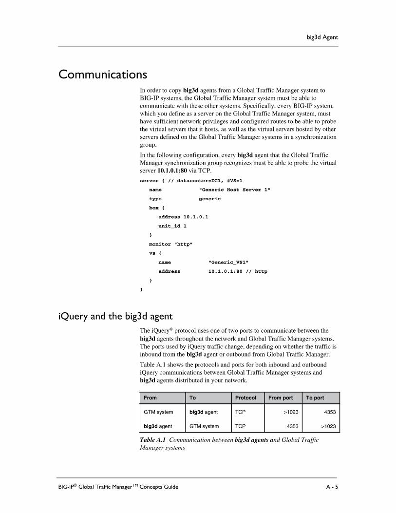
big3d Agent
CommunicationsIn order to copy big3d agents from a Global Traffic Manager system toBIG-IP systems, the Global Traffic Manager system must be able tocommunicate with these other systems. Specifically, every BIG-IP system,which you define as a server on the Global Traffic Manager system, musthave sufficient network privileges and configured routes to be able to probethe virtual servers that it hosts, as well as the virtual servers hosted by otherservers defined on the Global Traffic Manager systems in a synchronizationgroup.
In the following configuration, every big3d agent that the Global TrafficManager synchronization group recognizes must be able to probe the virtualserver 10.1.0.1:80 via TCP.
server { // datacenter=DC1, #VS=1
name "Generic Host Server 1"
type generic
box {
address 10.1.0.1
unit_id 1
}
monitor "http"
vs {
name "Generic_VS1"
address 10.1.0.1:80 // http
}
}
iQuery and the big3d agentThe iQuery® protocol uses one of two ports to communicate between thebig3d agents throughout the network and Global Traffic Manager systems.The ports used by iQuery traffic change, depending on whether the traffic isinbound from the big3d agent or outbound from Global Traffic Manager.
Table A.1 shows the protocols and ports for both inbound and outboundiQuery communications between Global Traffic Manager systems andbig3d agents distributed in your network.
From To Protocol From port To port
GTM system big3d agent TCP >1023 4353
big3d agent GTM system TCP 4353 >1023
Table A.1 Communication between big3d agents and Global TrafficManager systems
BIG-IP® Global Traffic ManagerTM Concepts Guide A - 5

Appendix A
Table A.2 shows the protocols and corresponding ports used for iQuerycommunications between big3d agents and SNMP agents that run on hostservers.
Table A.3 shows the ports used for communications between big3d agentsand virtual servers that are not hosted by a BIG-IP system.
iQuery and firewallsThe payload information of an iQuery packet contains information thatpotentially requires network address translation when there is a firewall inthe path between the big3d agent and the Global Traffic Manager system.The firewall translates only the packet headers, not the payloads.
The virtual server translation option resolves this issue. When you configureaddress translation for virtual servers, the iQuery packet stores the originalIP address in the packet payload itself. When the packet passes through afirewall, the firewall translates the IP address in the packet header normally,but the IP address within the packet payload is preserved. Global TrafficManager reads the IP address out of the packet payload, rather than out ofthe packet header.
For example, firewall separates the path between a BIG-IP system running abig3d agent, and the Global Traffic Manager system. The packet addressesare translated at the firewall. However, addresses within the iQuery payloadare not translated, and they arrive at the BIG-IP system in their originalstates.
From To Protocol From port To port Purpose
big3d agent host SNMP agent UDP >1023 161 Ephemeral ports used to makeSNMP queries for host statistics
host SNMP agent big3d agent UDP 161 >1023 Ephemeral ports used to receivehost statistics using SNMP
Table A.2 Communication between big3d agents and SNMP agents on hosts
From To Protocol From port To port Purpose
big3d agent virtual server UDP >1024 ServicePort
Ephemeral ports used to monitorhost virtual server
big3d agent virtual server TCP >1024 ServicePort
Ephemeral ports used to monitorhost virtual servers
Table A.3 Communication between big3d agents and virtual servers not hosted by BIG-IP systems
A - 6

big3d Agent
Communications between Global Traffic Managers, big3d agents,and local DNS servers
Table A.4 shows the protocols and ports that the big3d agent uses whencollecting path data for local DNS servers.
From To Protocol From port To port Purpose
big3d LDNS ICMP N/A N/A Probe using ICMP pings
big3d LDNS TCP >1023 53 Probe using TCP (Cisco® routers: allowestablish)
LDNS big3d TCP 53 >1023 Replies using TCP (Cisco® routers: allowestablish)
big3d LDNS UDP 53 33434 Probe using UDP or traceroute utility
LDNS big3d ICMP N/A N/A Replies to ICMP, UDP pings, or tracerouteprobes
big3d LDNS dns_revdns_dot
>1023 53 Probe using DNS rev or DNS dot
LDNS big3d dns_revdns_dot
53 >1023 Replies to DNS rev or DNS dot probes
Table A.4 Communications between big3d agents and local DNS servers
BIG-IP® Global Traffic ManagerTM Concepts Guide A - 7

Appendix A
A - 8

B
Probes
• Introduction
• About iQuery
• Probe responsibility
• Probes and the big3d agent
• LDNS probes
• Probes and log entries


Probes
IntroductionWhen you install a Global Traffic Manager™ system in a network, thatsystem typically works within a larger group of BIG-IP® products. Theseproducts include other Global Traffic Manager systems, Link Controller™systems, and Local Traffic Manager™ systems. Global Traffic Managermust be able to communicate with these other systems to maintain anaccurate assessment of the health and availability of different networkcomponents. For example, Global Traffic Manager must be able to acquirestatistical data from resources that are managed by Local Traffic Manager ina different data center. BIG-IP systems acquire this information through theuse of probes. A probe is an action a BIG-IP system takes to acquire datafrom other network resources.
Probes are an essential means by which Global Traffic Manager tracks thehealth and availability of network resources; however, it is equallyimportant that the responsibility for conducting probes be distributed acrossas many BIG-IP products as possible. This distribution ensures that no onesystem becomes overloaded with conducting probes, which can cause adecrease in performance in the other tasks for which a BIG-IP system isresponsible.
To distribute probe requests effectively across multiple BIG-IP systems,Global Traffic Manager systems employ several different technologies andmethodologies, including:
• iQuery®, which is the communication protocol used between GlobalTraffic Manager systems and the big3d agents that reside on otherBIG-IP systems
• A selection methodology that determines which Global Traffic Manageris responsible for managing the probe request
• A selection methodology that determines which big3d agent actuallyconducts the probe
One of the important concepts to remember when understanding how GlobalTraffic Manager acquires network data is that the process consists of severaltasks:
• Global Traffic Manager is chosen to be responsible for the probe.
• Global Traffic Manager delegates the probe to a big3d agent.
• The big3d agent conducts the probe.
• The big3d agent broadcasts the results of the probe, allowing all GlobalTraffic Manager systems to receive the information.
BIG-IP® Global Traffic ManagerTM Concepts Guide B - 1

Appendix B
About iQueryAt the heart of probe management with Global Traffic Manager systems isiQuery, the communications protocol that these systems use to sendinformation from one system to another. With iQuery, Global TrafficManager systems in the same synchronization group can share configurationsettings, assign probe requests to big3d agents, and receive data on thestatus of network resources.
The iQuery protocol is an XML protocol that is sent between each systemusing gzip compression and SSL. These communications can only beallowed between systems that have a trusted relationship established, whichis why configuration tools such as big3d_install, bigip_add, and gtm_addare critical when installing or updating Global Traffic Manager systems. Iftwo systems have not exchanged their SSL certificates, they cannot shareinformation with each other using iQuery.
In addition to requiring trusted relationships, systems send iQuerycommunications only on the VLAN on which the system received theincoming message. Also, iQuery communications occur only within thesame synchronization group. If your network consists of twosynchronization groups, with each group sharing a subset of networkresources, these groups probe the network resources and communicate withiQuery separately.
Generally, iQuery communications require no user intervention; however,on occasion it can be necessary to view the data transmitted between eachsystem. For example, you might be troubleshooting the reason that a GlobalTraffic Manager system is exhibiting a particular behavior. In such asituation, you can use the command, iqdump.
B - 2
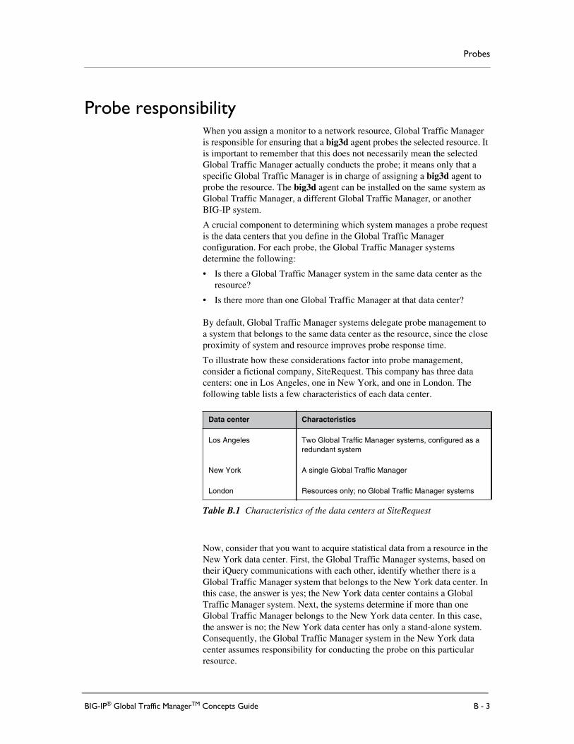
Probes
Probe responsibilityWhen you assign a monitor to a network resource, Global Traffic Manageris responsible for ensuring that a big3d agent probes the selected resource. Itis important to remember that this does not necessarily mean the selectedGlobal Traffic Manager actually conducts the probe; it means only that aspecific Global Traffic Manager is in charge of assigning a big3d agent toprobe the resource. The big3d agent can be installed on the same system asGlobal Traffic Manager, a different Global Traffic Manager, or anotherBIG-IP system.
A crucial component to determining which system manages a probe requestis the data centers that you define in the Global Traffic Managerconfiguration. For each probe, the Global Traffic Manager systemsdetermine the following:
• Is there a Global Traffic Manager system in the same data center as theresource?
• Is there more than one Global Traffic Manager at that data center?
By default, Global Traffic Manager systems delegate probe management toa system that belongs to the same data center as the resource, since the closeproximity of system and resource improves probe response time.
To illustrate how these considerations factor into probe management,consider a fictional company, SiteRequest. This company has three datacenters: one in Los Angeles, one in New York, and one in London. Thefollowing table lists a few characteristics of each data center.
Now, consider that you want to acquire statistical data from a resource in theNew York data center. First, the Global Traffic Manager systems, based ontheir iQuery communications with each other, identify whether there is aGlobal Traffic Manager system that belongs to the New York data center. Inthis case, the answer is yes; the New York data center contains a GlobalTraffic Manager system. Next, the systems determine if more than oneGlobal Traffic Manager belongs to the New York data center. In this case,the answer is no; the New York data center has only a stand-alone system.Consequently, the Global Traffic Manager system in the New York datacenter assumes responsibility for conducting the probe on this particularresource.
Data center Characteristics
Los Angeles Two Global Traffic Manager systems, configured as aredundant system
New York A single Global Traffic Manager
London Resources only; no Global Traffic Manager systems
Table B.1 Characteristics of the data centers at SiteRequest
BIG-IP® Global Traffic ManagerTM Concepts Guide B - 3

Appendix B
In situations where more than one Global Traffic Manager belongs to a datacenter, the systems use an algorithm to distribute the responsibility forprobes equally among Global Traffic Manager systems. This distributionensures that each Global Traffic Manager has an equal chance of beingresponsible for managing a probe request.
To demonstrate how probe requests are delegated between two GlobalTraffic Manager systems at the same data center, consider again the networkconfiguration at SiteRequest. This time, the company needs to acquire datafrom a resource that resides at the Los Angeles data center. As with theprevious example, the first step identifies whether the Los Angeles datacenter has any Global Traffic Manager systems; in this case, the answer isyes. The next criteria is whether there is more than one Global TrafficManager at that data center; in this case, the answer is also yes: the LosAngeles data center has a redundant system configuration that consists oftwo Global Traffic Manager systems. Because there are two Global TrafficManager systems at this data center, each system compares the hash value ofthe resource with its own information; whichever Global Traffic Managerhas the closest value to the resource becomes responsible for managing theprobe request.
A final consideration is if a data center does not have any Global TrafficManager systems at all, such as the London data center in the configurationfor SiteRequest. In this situation, the responsibility for probing a resource atthat data center is divided among the other Global Traffic Manager systems;much in the same way as the responsibility is divided among Global TrafficManager systems within the same data center.
When Global Traffic Manager becomes responsible for managing a probe, itremains responsible for that probe until the network configuration changesin one of the following ways:
• Global Traffic Manager goes offline.
• A new Global Traffic Manager system is added to the data center.
• The network configuration of the resource (such as its IP address)changes.
B - 4

Probes
Probes and the big3d agentThe first stage in conducting a probe of a network resource is to select theGlobal Traffic Manager system. In turn, Global Traffic Manager delegatesthe probe to a big3d agent, which is responsible for querying the givennetwork resource for data.
The probe delegation of network resources process is similar to thetwo-tiered load balancing method Global Traffic Manager uses whendelegating traffic. With DNS traffic, Global Traffic Manager identifies thewide IP to which the traffic belongs, and then load balances that trafficamong the pools associated with the wide IP. After it selects a pool, thesystem load balances the request across the pool members within that pool.
Delegating probe requests occurs in a similar two-tiered fashion. First, theGlobal Traffic Manager systems within a synchronization group determinewhich system is responsible for managing the probe. This does notnecessarily mean that the selected Global Traffic Manager conducts theprobe itself; it means only that a specific Global Traffic Manager ensuresthat the probe takes place. Next, Global Traffic Manager selects one of theavailable big3d agents to actually conduct the probe. As each BIG-IPsystem has a big3d agent, the number of agents available to conduct theprobe depends on the number of BIG-IP systems.
To illustrate how these considerations factor into probe management,consider the fictional company, SiteRequest. This company has three datacenters: one in Los Angeles, one in New York, and one in London. Thefollowing table lists a few characteristics of each data center:
Consider that a Global Traffic Manager system in the Los Angeles datacenter has assumed responsibility for managing a probe for a networkresource. At this data center, the system can assign the probe to one of fourbig3d agents: one for each BIG-IP system at the data center. To select abig3d, Global Traffic Manager looks to see which big3d agent has thefewest number of probes for which it is responsible. The big3d agent withthe lowest number of probes is tasked with conducting the probe. Global
Data center Characteristics
Los Angeles Two Global Traffic Manager systems, configured as aredundant system
Two Local Traffic Manager systems
New York A single Global Traffic Manager
Two Local Traffic Manager systems, configured as aredundant system
London Resources only; no Global Traffic Manager systems
A single Local Traffic Manager
Table B.2 Characteristics of the data centers at SiteRequest
BIG-IP® Global Traffic ManagerTM Concepts Guide B - 5

Appendix B
Traffic Manager checks this statistic each time it needs to delegate theprobe; as a result, the selected big3d can change from probe instance toprobe instance.
In situations where a big3d agent does not reside in the same data center asthe resource, the designated Global Traffic Manager selects a big3d from allavailable big3d agents on the network. Again, the agent selected is the agentwith the fewest number of probe requests, and this check occurs each timethe probe is conducted.
For example, SiteRequest adds a new set of web servers in Tokyo. At thislocation, the company has yet to install its BIG-IP systems; however, thecurrent set of Global Traffic Manager systems in Los Angeles and NewYork are managing traffic to these web servers. When initiating a proberequest to determine the availability of one of these servers, a Global TrafficManager system is selected to manage the probe request. Then, that systemchooses a big3d agent to probe the web server, selecting any big3d agentlocated in Los Angeles, New York, or London.
B - 6

Probes
LDNS probesGlobal Traffic Manager systems are responsible for probes of local DNSservers (LDNS). Unlike probes conducted on internal systems, such as webservers, probes of local DNS servers require that the Global Traffic Managersystem verifies data from a resource that exists outside the network.Typically, this data is the path information Global Traffic Manager requireswhen conducting Quality of Service, Round Trip Time, Completion Rate,and Hops load balancing methods.
Note
If you do not use Quality of Service load balancing, Global Traffic Managerdoes not conduct probes of local DNS servers.
When a given LDNS makes a DNS request for a wide IP, that request is sentto a single Global Traffic Manager. Global Traffic Manager then creates anLDNS entry, and assigns that entry one of the following states:
• New: Global Traffic Manager has not come across this particular LDNSbefore
• Active: Global Traffic Manager already has an existing entry for thisLDNS
• Pending: Global Traffic Manager has been contacted by this LDNSbefore, however, this server has yet to respond to a probe from a GlobalTraffic Manager system on this network
In general, the New and Pending states are temporary states; an LDNSremains in one of these states only until it responds to the first probe requestfrom Global Traffic Manager. After Global Traffic Manager receives aresponse, the LDNS entry is moved to the Active state. Each Global TrafficManager within a given synchronization group shares the LDNS entries thatare assigned this state, resulting in the synchronization group having acommon list of known local DNS servers.
Unlike internal probes, LDNS probes are not load balanced across GlobalTraffic Manager systems. Instead, the Global Traffic Manager system thatthe LDNS first queries becomes responsible for the initial probe to thatLDNS. These probes are load balanced, however, across the multiple big3dagents, with preference given to big3d agents that either belong to the samedata center as the responding Global Traffic Manager, or belong to the samelink through which Global Traffic Manager received the LDNS query. Afterthe initial probe, an algorithm is used to load balance subsequent probesacross the available Global Traffic Manager systems.
BIG-IP® Global Traffic ManagerTM Concepts Guide B - 7

Appendix B
The process for identifying and managing LDNS probe requests is asfollows:
1. An LDNS sends a DNS request to Global Traffic Manager.
2. Global Traffic Manager that responds to the request determines if italready has an entry for the LDNS. If it does not, it creates an entrywith a status of New.
3. Global Traffic Manager delegates the probe of the LDNS to a big3dagent; preferably a big3d agent that resides in the same data centeras the Global Traffic Manager system.
4. When the LDNS responds to the probe, it sends its information toGlobal Traffic Manager.
5. Global Traffic Manager updates its entry for the LDNS, assigning itan Active status.
6. Global Traffic Manager synchronizes its list of active local DNSservers with the other members of its synchronization group.
B - 8

Probes
Probes and log entriesProbes are the means by which Global Traffic Manager tracks the health andavailability of network resources, and it is important that the responsibilityfor conducting probes is distributed across as many BIG-IP products aspossible. You can use information in the Global Traffic Manager log file todetermine how to fine tune the probes that you have configured. However,the probe logs feature is disabled by default. You must turn on the featurefor the probe information to appear in the log file.
If you want Global Traffic Manager to gather information about probes andsave it in the log file, you must set the database variableGTM.DebugProbeTuningInterval to a non-zero value. The value of thevariable indicates, in seconds, how often you want the system to add probeinformation to the log file. By default this variable is set to 0 (zero), whichdisables the logging of information about probes.
To change the value of the database variable, use the tmsh command:
modify / sys db gtm.debugprobetuninginterval value [database variable value]
For information about the command syntax you use to change this variable,see the tmsh man pages.
Probe information in the log fileThe probe information displays in the logs in the Configuration utility whenthe GTM setting on the Logs screen is set to the default value of Notice.When you set the GTM.DebugProbeTuningInterval database variable to anon-zero value, the log file contains information about probes including thenumber of local DNS servers, Global Traffic Manager systems, paths, andpersistence records in your network. The log file also includes theinformation in the following list.
◆ For monitors:
• The time in microseconds that each monitor spends in the activequeue
• For each active monitor, the log file displays the followinginformation:
• Base name
• Monitor name
• Number of total instances
BIG-IP® Global Traffic ManagerTM Concepts Guide B - 9

Appendix B
• Number of up instances and the average and maximum probetime for each up instance
• Number of down instances, the average probe time for eachdown instance, and a sorted list of reasons that the instance isdown. Each reason in the list is followed the number of instancesthat were marked down for this reason.
◆ For each Global Traffic Manager and Local Traffic Manager:
• Datacenter name
• Server name
• IP address
• Current tmm CPU usage
• Number of virtual servers in each state: up or down
• Active and pending queue sizes for monitors, SNMP monitors, andpaths
• Number of monitors that have received a down response from thesystem
◆ For each host server:
• Datacenter name
• Server name
• IP address
• CPU usage
• Memory usageNote: This value is -1, unless an SNMP monitor is assigned to theserver.
• Number of virtual servers in each state: up or down
B - 10

Glossary


Glossary
A record
The A record is the resource record that Global Traffic Manager™ returns toa local DNS server in response to a name resolution request. The A recordcontains a variety of information, including one or more IP addresses thatresolve to the requested domain name.
access control list (ACL)
An access control list is a list of local DNS server IP addresses that areexcluded from path probing or hops queries.
active unit
In a redundant system configuration, an active unit is a system that currentlyload balances name resolution requests. If the active unit in the redundantsystem fails, the standby unit assumes control and begins to load balancerequests.
alternate method
The alternate method specifies the load balancing mode that Global TrafficManager uses to pick a virtual server if the preferred method fails. See alsofallback method, preferred method.
big3d agent
The big3d agent is a monitoring agent that collects metrics informationabout server performance and network paths between a data center and aspecific local DNS server. Global Traffic Manager uses the informationcollected by the big3d agent for dynamic load balancing.
BIG-IP system
A BIG-IP system can be a Global Traffic Manager system (including thecurrent Global Traffic Manager system), a Local Traffic Manager™ system,or a Link Controller™ system.
BIND (Berkeley Internet Name Domain)
BIND is the most common implementation of the Domain Name System(DNS). BIND provides a system for matching domain names to IPaddresses. For more information, refer tohttp://www.isc.org/products/BIND.
bridge mode
Bridge mode instructs Global Traffic Manager to forward the traffic itreceives to another part of the network.
BIG-IP® Global Traffic ManagerTM Concepts Guide Glossary - 1

Glossary
CIDR (Classless Inter-Domain Routing)
Classless Inter-Domain Routing (CIDR) is an expansion of the IP addresssystem that allows a single IP address to be used to designate many uniqueIP addresses. A CIDR IP address looks like a standard IP address except thatit ends with a slash followed by a number, which is the IP network prefix.For example: 172.200.0.0/16
CNAME record
A canonical name (CNAME) record acts as an alias to another domainname. A canonical name and its alias can belong to different zones, so theCNAME record must always be entered as a fully qualified domain name.CNAME records are useful for setting up logical names for networkservices so that they can be easily relocated to different physical hosts.
completion rate
The completion rate is the percentage of packets that a server successfullyreturns during a given session.
Completion Rate mode
The Completion Rate mode is a dynamic load balancing mode thatdistributes connections based on which network path drops the fewestpackets, or allows the fewest number of packets to time out.
Configuration utility
The Configuration utility is the browser-based application that you use toconfigure the BIG-IP system.
content delivery network (CDN)
A content delivery network (CDN) is an architecture of web-based networkcomponents that helps dramatically reduce the wide-area network latencybetween a client and the content they wish to access. A CDN includes someor all of the following network components: wide-area traffic managers,Internet service providers, content server clusters, caches, and origin contentproviders.
custom monitor
A custom monitor is a user-created monitor. See also monitor, healthmonitor, performance monitor, pre-configured monitor.
data center
A data center is a physical location that houses one or more Global TrafficManager systems, BIG-IP systems, or host machines.
data center server
A data center server is any server recognized in the Global Traffic Managerconfiguration. A data center server can be any of the following: a GlobalTraffic Manager system, a BIG-IP system, or a host.
Glossary - 2

Glossary
destination statement
A destination statement defines the resource to which Global TrafficManager directs the name resolution request.
distributed application
A distributed application is a collection of wide IPs, data center, and links. Itis the highest level component that Global Traffic Manager supports.
DNSSEC (DNS Security Extensions)
DNSSEC is a set of extensions to DNS that protects a computer networkagainst most of the threats to the Domain Name System.
DNSSEC zones
DNSSEC zones are containers that map a domain name to a set of DNSSECkeys.
domain name
A domain name is a unique name that is associated with one or more IPaddresses. Domain names are used in URLs to identify particular web pages.For example, in the URL http://www.f5.com/index.html, the domain nameis f5.com.
draining requests
Draining requests refers to allowing existing sessions to continue accessinga specific set of resources while disallowing new connections.
Drop Packet mode
Drop Packet load balancing mode instructs Global Traffic Manager to donothing with a packet, and simply drop the request.
dynamic load balancing modes
Dynamic load balancing modes base the distribution of name resolutionrequests to virtual servers on the matrix of live data, such as current serverperformance and current connection load.
Dynamic Ratio weighting
Dynamic Ratio weighting is a methodology in which the systemcontinuously checks the performance of each link and sends traffic throughthe link with the best performance data.
EAV (Extended Application Verification)
EAV is a health check that verifies an application on a node by running thatapplication remotely. EAV health check is only one of the three types ofhealth checks available on a Link Controller™. See also health monitor,external monitor.
BIG-IP® Global Traffic ManagerTM Concepts Guide Glossary - 3

Glossary
EAV monitor
An EAV monitor checks the health of a resource by accessing the specifiedapplication.
ECV (Extended Content Verification)
On Global Traffic Manager, ECV is a service monitor that checks theavailability of actual content, (such as a file or an image) on a server, ratherthan just checking the availability of a port or service, such as HTTP on port80.
ECV monitor
An ECV monitor checks the health of a resource by sending a query forcontent using the specified protocol, and waiting to receive the content fromthe resource. See also monitor, health monitor, external monitor.
external monitor
An external monitor is a user-supplied health monitor. See also healthmonitor.
external system
An external system is any server with which Global Traffic Manager mustexchange information to perform its functions.
failover
Failover is the process whereby a standby unit in a redundant systemconfiguration takes over when a software failure or hardware failure isdetected on the active unit.
failover cable
The failover cable is the cable that directly connects the two system units ina hardware-based redundant system configuration.
fallback method
The fallback method is the third method in a load balancing hierarchy thatGlobal Traffic Manager uses to load balance a resolution request. GlobalTraffic Manager uses the fallback method only when the load balancingmodes specified for the preferred and alternate methods fail. Unlike thepreferred method and the alternate method, the fallback method uses neitherserver nor virtual server availability for load balancing calculations. See alsopreferred method, alternate method.
Global Availability mode
Global Availability is a static load balancing mode that bases connectiondistribution on a particular server order, always sending a connection to thefirst available server in the list. This mode differs from Round Robin modein that it searches for an available server always starting with the first server
Glossary - 4

Glossary
in the list, while Round Robin mode searches for an available server startingwith the next server in the list (with respect to the server selected for theprevious connection request).
Global Traffic Manager
Global Traffic Manager provides wide-area traffic management and highavailability of IP applications/services running across multiple data centers.
gtmd
The gtmd utility processes communications between two Global TrafficManager systems.
health monitor
A health monitor checks a node to see if it is up and functioning for a givenservice. If the node fails the check, it is marked down. Different monitorsexist for checking different services. See also monitor, custom monitor,pre-configured monitor, performance monitor.
host
A host is a network server that manages one or more virtual servers thatGlobal Traffic Manager uses for load balancing.
ICMP (Internet Control Message Protocol)
ICMP is an Internet communications protocol used to determine informationabout routes to destination addresses, such as nodes that are managed byBIG-IP systems.
iQuery
The iQuery® protocol is used to exchange information between GlobalTraffic Manager systems and BIG-IP systems. The iQuery protocol isofficially registered with IANA for port 4353, and works on UDP and TCPconnections.
iRule
An iRule is a user-written script that controls the behavior of a connectionpassing through the Global Traffic Manager™ system. iRules® are an F5Networks feature and are frequently used to direct certain connections to anon-default load balancing pool. However, iRules can perform other tasks,such as implementing secure network address translation and enablingsession persistence.
key-signing key
Global Traffic Manager uses key signing keys to sign only the DNSKEYrecord of a DNSSEC record set. See also DNSSEC (DNS SecurityExtensions), DNSSEC zones, and zone-signing key.
BIG-IP® Global Traffic ManagerTM Concepts Guide Glossary - 5

Glossary
Kilobytes/Second mode
The Kilobytes/Second mode is a dynamic load balancing mode thatdistributes connections based on which available server currently processesthe fewest kilobytes per second.
LDNS
An LDNS is a server that makes name resolution requests on behalf of aclient. With respect to Global Traffic Manager, local DNS servers are thesource of name resolution requests.
Least Connections mode
The Least Connections mode is a dynamic load balancing mode that basesconnection distribution on which server currently manages the fewest openconnections.
link
A link is a logical representation of a physical device (router), whichconnects your network to the rest of the Internet.
Link Controller
Link Controller™ is an IP application switch that manages traffic to andfrom a site across multiple links, regardless of connection type or provider.
listener
A listener is an object that listens for DNS queries. A listener instructsGlobal Traffic Manager to listen for network traffic destined for a specificIP address.
load balancing methods
Load balancing methods are the settings that specify the hierarchical orderin which Global Traffic Manager uses three load balancing modes. Thepreferred method specifies the first load balancing mode that Global TrafficManager tries, the alternate method specifies the next load balancing modeto try if the preferred method fails, and the fallback method specifies the lastload balancing mode to use if both the preferred and the alternate methodsfail. See also alternate method, fallback method, and preferred method.
load balancing mode
A load balancing mode is the way in which Global Traffic Managerdetermines how to distribute connections across an array.
logical network components
Logical components are abstractions of network resources, such as a virtualservers. See also physical network components.
Glossary - 6

Glossary
metrics information
Metrics information is the data that is typically collected about the pathsbetween BIG-IP systems and local DNS servers. Metrics information is alsocollected about the performance and availability of virtual servers. Metricsinformation is used for load balancing, and it can include statistics such asround trip time, packet rate, and packet loss.
monitor
A monitor is a software utility that specializes in a specific metric of aGlobal Traffic Manager resource. A monitor tests to see if a given resourceresponds as expected. See also custom monitor, pre-configured monitor,health monitor, performance monitor.
monitor template
A monitor template is an abstraction that exists within the Global TrafficManager system for each monitor type, and contains a group of settings anddefault values.
named
The named daemon manages domain nameserver software.
nameserver
A nameserver is a server that maintains a DNS database, and resolvesdomain name requests to IP addresses using that database.
name resolution
Name resolution is the process by which a nameserver matches a domainname request to an IP address, and sends the information to the clientrequesting the resolution.
Network Time Protocol (NTP)
Network Time Protocol functions over the Internet to synchronize systemclocks to Universal Coordinated Time. NTP provides a mechanism to setand maintain clock synchronization within milliseconds.
node
A node is a logical object on the BIG-IP system that identifies the IP addressof a physical resource on the network, such as a web server.
Node mode
The Node mode instructs Global Traffic Manager to process traffic locally,and send the appropriate DNS response back to the querying server.
BIG-IP® Global Traffic ManagerTM Concepts Guide Glossary - 7

Glossary
NS record
A nameserver (NS) record is used to define a set of authoritativenameservers for a DNS zone. A nameserver is considered authoritative forsome given zone when it has a complete set of data for the zone, allowing itto answer queries about the zone on its own, without needing to consultanother nameserver.
packet rate
The packet rate is the number of data packets per second processed by aserver.
Packet Rate mode
The Packet Rate mode is a dynamic load balancing mode that distributesconnections based on which available server currently processes the fewestpackets per second.
path
A path is a logical network route between a data center server and a localDNS server.
path probing
Path probing is the process of collecting metrics data, such as round triptime and packet rate, for a given path between a requesting LDNS and a datacenter server.
performance monitor
Performance monitors check the performance of a pool or virtual server, anddynamically load balance traffic accordingly. See also monitor,pre-configured monitor, custom monitor, health monitor.
persistence
On Global Traffic Manager, persistence is a series of related requestsreceived from the same local DNS server for the same wide IP name. Whenpersistence is activated, Global Traffic Manager sends all requests from aparticular local DNS server for a specific wide IP to the same virtual server,instead of load balancing the requests.
physical network components
Physical network components have a direct correlation with one or morephysical entities on the network. See also logical network components.
picks
Picks represent the number of times a particular virtual server is selected toreceive a load balanced connection.
Glossary - 8

Glossary
pool
A pool is a group of virtual servers managed by a BIG-IP system, or a host.Global Traffic Manager load balances among pools (using the Pool LBMode), as well as among individual virtual servers.
pool-level load balancing
With pool-level load balancing, after Global Traffic Manager uses wideIP-level load balancing to select the best available pool, it uses a pool-levelload balancing to select a virtual server within that pool. If the first virtualserver within the pool is unavailable, Global Traffic Manager selects thenext best virtual server based on the load balancing mode assigned to thatpool. See also tiered load balancing and wide IP-level load balancing.
pool ratio
A pool ratio is a ratio weight applied to pools in a wide IP. If the Pool LBmode is set to Ratio, Global Traffic Manager uses each pool for loadbalancing in proportion to the weight defined for the pool.
preferred method
The preferred method specifies the first load balancing mode that GlobalTraffic Manager uses to load balance a resolution request. See also alternatemethod, fallback method, and load balancing methods.
pre-configured monitor
Pre-configured monitors are monitors that Global Traffic Manager provides.See also monitor, custom monitor, and health monitor.
probe
A probe is a specific query, initiated by a big3d agent, that attempts togather specific data from a given network resource. Probes are most oftenemployed when a health monitor attempts to verify the availability of aresource.
QOS equation mode
The QOS equation is the equation on which the Quality of Service loadbalancing mode is based. The equation calculates a score for a given pathbetween a data center server and a local DNS server. The Quality of Servicemode distributes connections based on the best path score for an availabledata center server. You can apply weights to the factors in the equation, suchas round trip time and completion rate.
Quality of Service mode
The Quality of Service load balancing mode is a dynamic load balancingmode that bases connection distribution on a configurable combination ofthe packet rate, completion rate, round trip time, hops, virtual servercapacity, kilobytes per second, link capacity, and topology information.
BIG-IP® Global Traffic ManagerTM Concepts Guide Glossary - 9

Glossary
ratio
A ratio is the parameter in a virtual server statement that assigns a weight tothe virtual server for load balancing purposes.
Ratio mode
The Ratio load balancing mode is a static load balancing mode thatdistributes connections across an pool of virtual servers in proportion to theratio weight assigned to each individual virtual server.
Ratio weighting
Ratio weighting is a methodology in which the system uses a frequency thatyou set to determine to which link to send traffic.
redundant system configuration
A redundant system configuration is a pair of units that are configured forfailover. One system runs as the active unit and the other system runs as thestandby unit. If the active unit fails, the standby unit takes over and managesresolution requests.
region
A region is a customized collection of topologies. See topology.
request source statement
A request source statement defines the origin of a name resolution requestfor a connection.
resource record
A resource record is a record in a DNS database that stores data associatedwith domain names. A resource record typically includes a domain name, aTTL, a record type, and data specific to that record type. See also A record,CNAME record, NS record.
root nameserver
A root nameserver is a master DNS server that maintains a complete DNSdatabase. There are approximately 13 root nameservers in the world thatmanage the DNS database for the World Wide Web.
Round Robin mode
Round Robin mode is a static load balancing mode that bases connectiondistribution on a set server order. Round Robin mode sends a connectionrequest to the next available server in the order.
Glossary - 10

Glossary
round trip time (RTT)
Round trip time is the calculation of the time (in microseconds) that a localDNS server takes to respond to a ping issued by the big3d agent running ona data center server. Global Traffic Manager takes RTT values into accountwhen it uses dynamic load balancing modes.
Round Trip Time mode
Round Trip Time is a dynamic load balancing mode that bases connectiondistribution on which virtual server has the fastest measured round trip timebetween the data center server and the local DNS server.
router hops
Router hops are intermediate system transitions along a given network path.
Router mode
Router mode instructs Global Traffic Manager to forward the traffic itreceives to another DNS server.
self IP address
A self IP address is an IP address that you define on a VLAN of a BIG-IPsystem. This term does not apply to the management IP address of a BIG-IPsystem, or to IP addresses on other devices.
server
A server is a physical device on which you can configure one or morevirtual servers.
Setup utility
The Setup utility is a utility that takes you through the initial systemconfiguration process. The Setup utility runs automatically when you turnon a system for the first time.
Simple monitor
A Simple monitor checks the health of a resource by sending a packet usingthe specified protocol, and waiting for a response from the resource. Seealso health monitor.
SNMP (Simple Network Management Protocol)
SNMP is the Internet standard protocol, defined in STD 15, RFC 1157, thatwas developed to manage nodes on an IP network.
standby unit
A standby unit is the system in a redundant system configuration that isalways prepared to become the active unit if the active unit fails.
BIG-IP® Global Traffic ManagerTM Concepts Guide Glossary - 11
Glossary
static load balancing modes
Static load balancing modes base the distribution of name resolutionrequests to virtual servers on a pre-defined list of criteria and server andvirtual server availability; they do not take current server performance orcurrent connection load into account. See also dynamic load balancingmodes.
synchronization
Synchronization means that each Global Traffic Manager regularlycompares the timestamps of its configuration files with the timestamps ofthe configuration files on the other Global Traffic Manager systems on thenetwork.
synchronization group
A synchronization group is a group of Global Traffic Manager systems thatsynchronize system configurations and zone files (if applicable). Allsynchronization group members receive broadcasts of metrics data from thebig3d agents throughout the network. All synchronization group membersalso receive broadcasts of updated configuration settings from GlobalTraffic Manager that has the latest configuration changes.
tiered load balancing
Tiered load balancing is load balancing that occurs at more than one pointduring the resolution process. See also wide IP-level load balancing andpool-level load balancing.
tmsh
The Traffic Management Shell (tmsh) is a command-line utility that youcan use to configure Global Traffic Manager.
topology
A topology is a set of characteristics that identify the origin of a given nameresolution request.
Topology mode
The Topology mode is a static load balancing mode that bases thedistribution of name resolution requests on the weighted scores for topologyrecords. Topology records are used by the Topology load balancing mode toredirect DNS queries to the closest virtual server, geographically, based onlocation information derived from the DNS query message.
topology record
A topology record specifies a score for a local DNS server location endpointand a virtual server location endpoint.
Glossary - 12

Glossary
topology score
The topology score is the weight assigned to a topology record when GlobalTraffic Manager is filtering the topology records to find the best virtualserver match for a DNS query.
topology statement
A topology statement is a collection of topology records.
TTL (Time to Live)
The TTL is the number of seconds for which a DNS record or metric isvalid, or for which a DNSSEC key is cached by a client resolver. When aTTL expires, the server usually must refresh the information before using itagain. See also DNSSEC (DNS Security Extensions).
unavailable
The unavailable status is used for data center servers and virtual servers.When a data center server or virtual server is unavailable, Global TrafficManager does not use it for load balancing.
unknown
The unknown status is used for data center servers and virtual servers.When a data center server or virtual server is new to Global Traffic Managerand does not yet have metrics information, Global Traffic Manager marksits status as unknown. Global Traffic Manager can use unknown servers forload balancing, but if the load balancing mode is dynamic, Global TrafficManager uses default metrics information for the unknown server until itreceives live metrics data.
up
The up status is used for data center servers and virtual servers. When a datacenter server or virtual server is up, the data center server or virtual server isavailable to respond to name resolution requests.
user configuration set (UCS)
A user configuration set is a backup file that you create for the BIG-IPsystem configuration data. When you create a UCS, the BIG-IP systemassigns a .ucs extension to the file name.
virtual server
A virtual server, in the context of Global Traffic Manager, is a combinationof an IP address and a port number that, together, provide access to anapplication or data source on your network.
BIG-IP® Global Traffic ManagerTM Concepts Guide Glossary - 13

Glossary
wide IP
A wide IP is a collection of one or more domain names that maps to one ormore groups of virtual servers managed either by BIG-IP systems, or byhost servers. Global Traffic Manager load balances name resolution requestsacross the virtual servers that are defined in the wide IP that is associatedwith the requested domain name.
wide IP-level load balancing
With wide IP-level load balancing, Global Traffic Manager load balancesrequests, first to a specific pool, and then to a specific virtual server in theselected pool. If the preferred, alternate, and fallback load balancingmethods that are configured for the pool or virtual server fail, then therequests fail, or the system falls back to DNS. See also tiered load balancingand pool-level load balancing.
wildcard listener
A wildcard listener monitors all traffic coming into your network, regardlessof the destination IP address of the given DNS request.
zone
In DNS terms, a zone is a subset of DNS records for one or more domains.
zone file
In DNS terms, a zone file is a database set of domains with one or manydomain names, designated mail servers, a list of other nameservers that cananswer resolution requests, and a set of zone attributes, which are containedin an SOA record.
zone-signing key
Global Traffic Manager uses a zone-signing key to sign all of the record setsin a DNSSEC zone. See also DNSSEC (DNS Security Extensions), DNSSECzones, and key-signing key.
ZoneRunner
ZoneRunner™ is the utility that allows you manage your resource records,zone files, and named configuration associated with your implementation ofDNS and BIND.
Glossary - 14

Index


Index
AA record, defined 16-4AAAA record, defined 16-4address exclusion list 13-4alias addresses 11-5alternate load balancing method 7-2applications
See distributed applications. 6-8availability, defined 8-3
Bbig3d agent
and broadcasting sequence A-3and configuration trade-offs A-3and data collection A-3and dynamic load balancing 7-6and iQuery A-5and metrics A-2installing A-3introducing A-1selecting for probe requests B-3, B-5setting up A-3using with system communications 3-4
billing, and links 5-9BIND configuration and DNSSEC 10-3Bridge mode, about 4-1broadcast sequence and big3d agent A-3
Ccache poisoning, preventing 10-1CNAME record, defined 16-4communications
and big3d A-5and probes B-1system 3-4
Completion Rate load balancing mode 7-6configuration tasks, about 3-1Configuration utility, about 1-3connections, resuming 8-5CPU load balancing mode 7-6custom monitors
about 11-3and monitor templates 11-4and pre-configured monitor 11-3defined 11-3
Ddata center statistics 12-7data centers
about configuring 5-2and defining physical network components 5-1configuring 5-2defined 2-2
data collection, and big3d agent A-3
data graphs, performance 14-1denial of service, preventing 10-1dependencies
creating for virtual servers 8-4organizing for virtual servers 8-4setting 6-8
distributed applicationsabout 6-9and dependencies 6-8and persistent connections 6-10and statistics for 12-3and wide IPs 2-5defined 2-5, 6-8
DNAME record,defined 16-4DNS zone files, about synchronization 3-7DNSSEC key expiration 10-2DNSSEC keys
about 10-1about generations of 10-1about key-signing keys 10-1about zone-signing keys 10-1and TTL 10-2
DNSSEC resource records 10-3DNSSEC zones, about 10-1DNSSEC, and independence from BIND 10-3domain names, and system validation 3-10domain validation, configuring 3-10Drain Persistent Requests option 8-6Drop Packet load balancing mode 7-3dynamic load balancing modes
and big3d agents 7-6and fallback load balancing method 7-2defined 7-1overview 7-6See also Completion Rate load balancing mode.See also CPU load balancing mode.See also Hops load balancing mode.See also Kilobyte/Second load balancing mode.See also Least Connections load balancing mode.See also Packet Rate load balancing mode.See also Quality of Service load balancing mode.See also Round Trip Times load balancing mode.See also Virtual Server Score load balancing mode.See also VS Capacity load balancing mode.
dynamic ratioand Quality of Service mode 7-8introducing 7-9using with Quality of Service mode 7-9
EEAV monitors 11-2ECV monitors 11-2event declarations 15-3event execution, about terminating 15-3event-based traffic management 15-3
BIG-IP® Global Traffic ManagerTM Concepts Guide Index - 1

Index
Ffailover
for hardware-based 3-3for network-based 3-3
Fallback IP load balancing mode 7-4fallback load balancing
and load balancing mode usage 7-2introducing 7-10selecting 7-2
features of Global Traffic Manager 1-1firewalls and iQuery A-6forward zone files, defined 16-2
GGlobal Availability load balancing mode 7-4Global Traffic Manager
and components 2-1and DNSSEC keys and zones 10-1and operation modes 4-1defining current 3-2, 5-3selecting for probe requests B-3
graphs for performance data 14-1GTM Performance graph 14-1GTM Request Breakdown graph 14-1gtmd 3-4
Hhardware-based failover 3-3health monitor settings 11-1health monitors
about pre-configured 11-2and alias addresses 11-5and default settings 11-1and disabled resources 3-9and health monitor types 11-2and links 5-9and number of queries 3-9and reverse mode 11-5and servers to 5-5and transparent mode 11-5assigning heartbeat intervals 3-8associating resources to 11-7defined 11-2determining availability with 8-3introducing 11-1
heartbeat interval 3-8HINFO record, defined 16-5HINT zone files, defined 16-2Hops load balancing mode 7-7host servers, defined 5-5
IID hacking, preventing 10-1ignore path TTL option 7-11
internet protocols 1-2iqdump command, using B-2iQuery
and firewalls A-6and probes B-1and VLANs B-2defined A-5using with system communications 3-4
iRule evaluation, controlling 15-3iRules
and wide IPs 6-7assigning 15-3introducing 15-1
is not operator 9-3is operator 9-3
Kkey expiration 10-2key generations, understanding DNSSEC keys 10-1key-signing keys, about 10-1Kilobytes/Second load balancing mode 7-7
Llast resort pool 8-7LDNS probes B-7Least Connections load balancing mode 7-7limit setting
defined 8-3using Kilobytes 8-3using Packets 8-3
limit settingsSee limit thresholds.
limit thresholdsabout 5-5and BIG-IP systems 8-3and pool members 5-7and pools 5-6and servers 5-6and virtual servers 5-6using Total Connections 8-3
link statistics 12-8links
about managing 5-9and defining physical network components 5-1and monitors 5-9billing 5-9defined 2-2weighting 5-9
listeners, defined 2-4load balancing
and dynamic modes 7-6and pools 7-1and wide IPs 7-1enabling ignore path TTL option 7-11introducing 7-1
Index - 2

Index
using alternate methods 7-2using dynamic load balancing modes 7-1using fallback method 7-10using pool-level 7-1using static load balancing modes 7-1using tiered 7-1using Topology mode 9-4using wide IP-level 7-1verifying virtual server availability 7-11
load balancing methodsselecting 7-1using fallback load balancing 7-2
load balancing mode usage 7-2load balancing modes
about Topology 7-6and name resolution requests 7-1defined 7-2using Completion Rate 7-6using CPU 7-6using Drop Packet 7-3using Fallback IP 7-4using Global Availability 7-4using Hops 7-7using Kilobytes/Second 7-7using Least Connections 7-7using None 7-3, 7-4using Packet Rate 7-7using Quality of Service 7-8using Ratio 7-5using Return to DNS 7-3, 7-5using Round Robin 7-5using Round Trip Times 7-8using static 7-3using Static Persist 7-5using Virtual Server Score 7-8using VS Capacity 7-8
load balancing servers, defined 5-4local DNS
excluding from probes 13-4removing from probes 13-4
local DNS statistics 12-13Local Traffic Manager
and resources 1-2defined 5-4
logical network componentsand distributed applications 2-5and listeners 2-4and pools 2-4and wide IPs 2-4defined 2-4, 5-1introducing 6-1
Longest Match option 9-4
Mmanual resume 8-5master zone files
See primary zone files.metrics
defined 13-2introducing 13-1
metrics collectionand big3d agent A-2and probes 13-4and TTL and timers 13-5excluding local DNS from probes 13-4removing local DNS from probes 13-4sequence A-3setting TTL and timer values 13-5
monitorsconfiguring global 3-8defined 8-3See also health monitors. 5-5summary of types 11-2
mx record, defined 16-5
Nnamed.conf file 16-7network management tools 1-2network traffic flows, graphs 14-1network-based failover
and redundant system configurations 3-3Node mode
and listeners 4-1defined 4-1
NoError response, implementing 6-7None load balancing mode
using 7-4using to skip load balancing 7-3
NS record, defined 16-5
Ooperators, defined 9-3
PPacket Rate load balancing mode 7-7paths statistics 12-12performance data, viewing 14-1persistence records 12-15persistent connections
and distributed applications 6-10and persistent records 12-15draining 8-6introducing 8-6
physical network componentsabout data centers 5-2and data centers 2-2and links 2-2
BIG-IP® Global Traffic ManagerTM Concepts Guide Index - 3

Index
and virtual servers 2-3introducing 5-1using servers 2-2
pool members, using with limit thresholds 5-7pool statistics 12-6pool-level load balancing 7-1pools
adding to wide IPs 6-6and limit thresholds 5-6and topology load balancing 9-4defined 2-4, 6-3organizing virtual servers 6-2organizing within wide IPs 6-6weighting virtual servers 6-3weighting within wide IPs 6-6
pre-configured health monitors, about 11-2preferred load balancing method 7-2primary zone files, defined 16-2probes
and information in log file B-9and LDNS B-7defined B-1determining responsibility for B-3enabling logging B-9selecting big3d agents B-5selecting Global Traffic Manager systems B-3using log entries to tune B-9
PTR record, defined 16-5
QQuality of Service load balancing mode
and default settings 7-8customizing 7-8introducing 7-8using dynamic ratio 7-8, 7-9
RRatio load balancing mode 7-5regions 9-4request source statements 9-3requests
draining 8-6on performance graph 14-1
resolutions, on performance graph 14-1resource availability
and limit settings 8-3and monitor availability requirements 8-3and monitors 11-2and virtual server dependencies 8-3defined 8-3
resource health, determining 8-2resource records
about DNSSEC and BIND 10-3and NS records 16-5and PTR records 16-5
and SOA records 16-4and types of records 16-4viewing DNSSEC 10-3
Return to DNS load balancing modeusing 7-5using to skip load balancing 7-3
reverse mode 11-5Round Robin load balancing mode 7-5Round Trip Times load balancing mode 7-8Router mode, about 4-1
Ssecondary zone files, defined 16-2security features 1-1server statistics 12-9servers
about 2-2and BIG-IP systems defined 5-3and defining physical network components 5-1and limit thresholds 5-6defining current Global Traffic Manager 5-3defining host servers 5-5defining load balancing servers 5-4defining Local Traffic Managers 5-4introducing 5-3
setup tasks, about 3-1Setup Utility, about 3-1simple monitors 11-2slave zone files
See secondary zone files.SMTP 1-2SNMP MIB 1-3SNMP, using for system communications 3-5SOA record, defined 16-4spoofing, preventing 10-1SRV record, defined 16-5SSL 1-1static load balancing modes
about Topology 7-6and alternate load balancing methods 7-1and fallback load balancing method 7-2defined 7-1described 7-3using Drop Packet 7-3using Fallback IP 7-4using Global Availability 7-4using None 7-3, 7-4using Ratio 7-5using Return to DNS 7-3, 7-5using Round Robin 7-5using Static Persist 7-5
Static Persist load balancing mode 7-5statistics
accessing 12-2and data centers 12-7
Index - 4

Index
and distributed applications 12-3and links 12-8and local DNS servers 12-13and paths 12-12and pools 12-6and servers 12-9and status summary 12-2and virtual servers 12-11and wide IPs 12-5described 12-3
status code, defined 8-2status summary 12-2stub zone files, defined 16-2synchronization
and DNS zone files 3-7defined 3-6
synchronization groups 3-6system communications 3-4system resources
and dependencies 8-4associating health monitors to 11-7determining availability 8-3resuming connections to 8-5
systemsavailability 8-3
Ttasks
about configuration 3-1about setup 3-1
Tcl syntax 15-2tiered load balancing 7-1timer values
and metrics collection 13-5introducing 13-5
tmsh, about 1-4Tools Command Language syntax 15-2topologies
and longest match option 9-4and pools 9-4and records 9-3and regions 9-4and request source statements 9-3and Topology Threshold option 9-4and wide IPs 9-4introducing 9-1setting up 9-3
Topology load balancing mode, defined 7-6topology records, defined 9-3topology score, and topology records 9-3topology statement 9-3Topology Threshold option 9-4traffic management shell, about 1-4transparent mode 11-5
TTL valuesand metrics collection 13-5introducing 13-5
TTL, and DNSSEC keys 10-2TXT record, defined 16-5
Vvalidation, domain 3-10Verify Virtual Server Availability option 7-11views, and BIND 9 16-6Virtual Server Score load balancing mode 7-8virtual server statistics 12-11virtual servers
about 2-3about managing 5-8and defining physical network components 5-1and iRules 15-3and limit thresholds 5-6creating dependencies 8-4organizing dependencies 8-4organizing within pools 6-2weighting within pools 6-3
VS Capacity load balancing mode 7-8
Wweight
See topology score, and topology records.weighting, using with links 5-9when keyword, using with iRules 15-3wide IP load balancing, and load balancing modes 7-2wide IP statistics 12-5wide IP-level load balancing 7-1wide IPs
adding pools to 6-6and iRules 6-7and persistent connections 8-6and topology load balancing 9-4defined 2-4maintaining 6-5organizing pools 6-6setting up 3-1weighting pools 6-6
wildcard charactersand wide IPs 6-5examples 6-5
wildcard listener, defined 4-2
Zzone files, about synchronization 3-7zones, about DNSSEC 10-1zone-signing keys, about 10-1
BIG-IP® Global Traffic ManagerTM Concepts Guide Index - 5