BG Spider Tutorial. Notes 1. Save A Lot (possibly after each step in case you make any mistakes –...
100
BG Spider Tutorial
-
Upload
leo-briggs -
Category
Documents
-
view
218 -
download
4
Transcript of BG Spider Tutorial. Notes 1. Save A Lot (possibly after each step in case you make any mistakes –...

BG Spider Tutorial

Notes
1. Save A Lot (possibly after each step in case you make any mistakes – THERE IS NO UNDO, and it gets complicated to correct mistakes sometimes with only a delete option)
2. Units are in inches and pounds3. X, Y are horizontal. Z is vertical4. All tree instructions start under “Preprocessor > Modeling” unless otherwise
specified5. Tree instructions are only listed once (however, you will need to use the same
operation more than once) in bold and italic 6. I recommend keeping keypoint numbering on (plot controls > numbering…)7. When creating areas by lines or by keypoints, select the lines or keypoints in
order, don’t cross over, ANSYS won’t understand8. Hitting apply keeps a window open, so you can hit apply multiple times to create
multiple keypoints, but on the last one you should either hit apply then cancel or just okay. If you hit apply then okay, you will have 2 keypoints.

1/8th of the Outer CylinderX Y Z
0 0 0
0 0 62
17 0 62
46 0 62
52 0 59
52 0 57
22 0 57
22 0 5
52 0 5
52 0 2.25
50 0 1.25
42.32 0 1.25
42.32 0 0
17 0 0
Create 14 keypoints (create > keypoints > in active CS) (you’re going to want to select the bottom view on the right hand side). Now, create lines between these keypoints as shown below (create > lines > straight lines).

Create the area to be extruded (creates > area > arbitrary > by lines), when done, click okay to exit the box. Select the lines in order – start at one line and then click the one with the coincident endpoint, until you complete a closed area (ANSYS is dumb and crossing lines and keypoints confuses it). Your area should look like the one below.

Create the volume – (Operate >> Extrude >> Areas >> About Axis) You will have to do this operation twice since the area we created is in the middle. First select the area, and hit okay in the little box. Then select the axis (keypoints 1 and 2 – in that order) and hit okay again. In the box where it offers a 360 degree rotation, type in 22.5 and hit okay. Repeat the process, making sure to select the face that lies on the X axis and type in -22.5 as the arc length, then hit okay. You should have 2 volumes, as shown below. You can turn on volume numbering (Plot Controls >> Numbering >> Volumes), you can also turn on keypoint numbering in the same window.
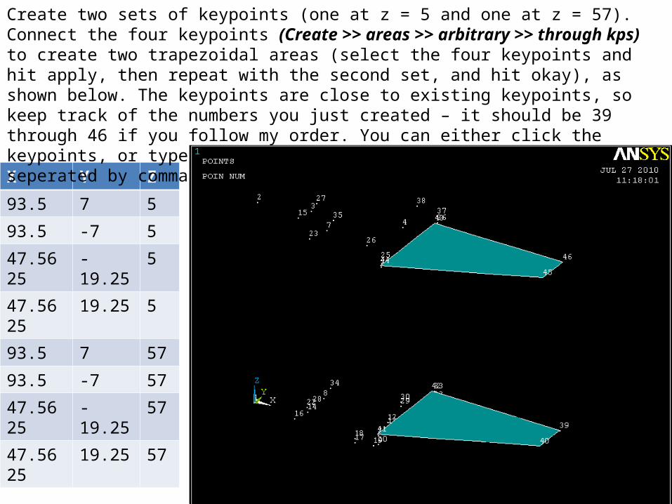
X Y Z
93.5 7 5
93.5 -7 5
47.5625 -19.25 5
47.5625 19.25 5
93.5 7 57
93.5 -7 57
47.5625 -19.25 57
47.5625 19.25 57
Create two sets of keypoints (one at z = 5 and one at z = 57). Connect the four keypoints (Create >> areas >> arbitrary >> through kps) to create two trapezoidal areas (select the four keypoints and hit apply, then repeat with the second set, and hit okay), as shown below. The keypoints are close to existing keypoints, so keep track of the numbers you just created – it should be 39 through 46 if you follow my order. You can either click the keypoints, or type them into the area creation window, in order, seperated by commas.

Now extrude the areas the appropriate distances - 2 for the top and -2.75 for the bottom, both in the z direction (Operate >> Extrude >> Areas >> by XYZ offset). To plot your volumes you can either type “vplot” into the command line, or click (plot >> volumes).

X Y Z
93.5 -7 90
95.49378 -7 90
95.49378 -1.4375 90
95.125 -1.4375 90
95.125 1.4375 90
95.49378 1.4375 90
95.49378 7 90
93.5 7 90
93.5 .625 90
93.5 0 90
93.5 .625 90
Create 11 more keypoints and connect them by lines to create the shape below. You can plot lines by typing “lplot” in the command line or clicking (plot >> lines).

Create fillets in the inner corners by selecting (create >> lines >> line fillet) and picking the two lines that intersect each other to form the inner corners. When prompted for the radius type in .3125 and hit apply. Repeat the steps and hit okay to create a second fillet. Your lines should look like this:

Create an area by these lines (remember the line fillet command has created 2 lines – one straight and one curved) and extrude it -107.141 in the z direction, using the “by XYZ offset command” your model should now look like this:

Now we can add all of the volumes together to create one volumes (operate >> booleans >> add >> volumes). Select all of the volumes and hit okay.

Select the two inner faces of the spider arm as shown, and extrude by XYZ offset, -75 in the X direction. Add these two volumes together, but keep it separate from the big volume.

X Y Z
22 0 8.875
22 0 53.125
25.875 0 5
25.875 0 57
Create 4 keypoints to be used as the end of two arcs. The third keypoint (the center) is already part of the model. After creating the keypoints create an arc by End Points and Rad (create >> lines >> arcs >> by keypoints and rad) the two end points are two sets of keypoints you just created and the third point is on the model, the radius should be 3.875 (select the endpoints, hit okay, then select the center and hit okay). After creating the arc, create two lines to complete the quarter circle and create an area by lines.

Extrude these two areas twice about an axis, once -5 degrees and once 5 degrees. Use the keypoints at 0,0,0 and 0,0,62 as your axis (select the bottom first, then top). Then add these to your volume. Then if you type vplot,*new volume number* in the command line you should have a volume that looks like this:

Take the two left side quarter circle faces and extrude them about the same axis 10 degrees. Then subtract them from the larger volume (operate >> booleans >> subtract >> volumes). Then you should have this volume (again you can type something like “vplot,3” if 3 is your volume number into the command line to see the new volume by itself):

Now extrude the two areas on the left side of the circle up and down by 3.875 to get rid of those wings. Subtract those volumes the same way you did before and you should get:

X Y Z
93.5 -.625 53.125
93.5 -.625 8.875
89.625 -.625 57
89.625 -.625 5
55.875 -.625 57
55.875 -.625 5
52 -.625 57
52 -.625 53.125
52 -.625 8.875
52 -.625 5
48.125 -.625 57
48.125 -.625 5
Create 12 new keypoints and create 6 new arcs (ANSYS doesn’t like to do 180 degree arcs so you’ll have to make two 90’s, and connect the rest of the new keypoints with lines to make 2 quarter circles and 2 half circles. Then create areas by lines, and extrude them 1.25 in the Y direction. Be careful to select the right keypoints – if you choose incorrectly improper lines and then areas are created. You can always type in your selection if you know the numbers. Finally, subtract the 4 small volumes from the larger volumes and you should now have:

Add these two volumes together to get one volume.

X Y Z
76 0 59
77.72251 0 59
79.19729 0 61.61247
90.11289 0 80.94858
93.5 0 86.94857
Create 5 new keypoints and connect them by lines – a sixth keypoint will be needed it is already on the model at 93.5,0,90. Then create an area by lines from these 6 lines.
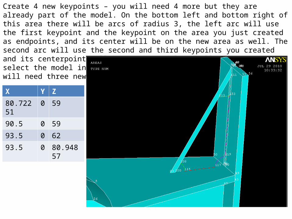
Create 4 new keypoints – you will need 4 more but they are already part of the model. On the bottom left and bottom right of this area there will be arcs of radius 3, the left arc will use the first keypoint and the keypoint on the area you just created as endpoints, and its center will be on the new area as well. The second arc will use the second and third keypoints you created and its centerpoint will be on the model as well (make sure you select the model in the XZ plane). Along with these two arcs you will need three new lines as shown below.
X Y Z
80.72251 0 59
90.5 0 59
93.5 0 62
93.5 0 80.94857

Create a new area by these 5 lines as well as a sixth line that is on the previously created area, to make a new area.

Extrude the thin area by 6.875 and -6.875 in the Y direction. Extrude the more complex area .625 and -.625 in the Y direction.

X Y Z
76 0 2.25
77.65418 0 2.25
78.9229 0 -.46852
89.03739 0 -22.141
90.90418 0 -26.141
89.25 0 -26.141
Create 6 new keypoints. Connect them with 6 new lines as we did in the last set. Then create an area by lines. The arcs and extra lines should be used for reference for the next slide’s instructions – in other words I forgot to take a screenshot.

Create 4 new keypoints – you will need 4 more but they are already part of the model. On the top left and top right of this area there will be arcs of radius 3, the left arc will use the first keypoint and the keypoint on the area you just created as endpoints, and its center will be on the new area as well. The second arc will use the second and third keypoints you created and its centerpoint will be on the model as well (make sure you select the model in the XZ plane). Along with these two arcs you will need three new lines as shown below. Extrude the thin piece 6.875 and -6.875 in the Y direction, and extrude the complex piece .625 and -.625 in the Y direction, as we did in the last step.
X Y Z
80.65418 0 2.25
90.5 0 2.25
93.5 0 -.75
93.5 0 -22.141

Add all the volumes together.

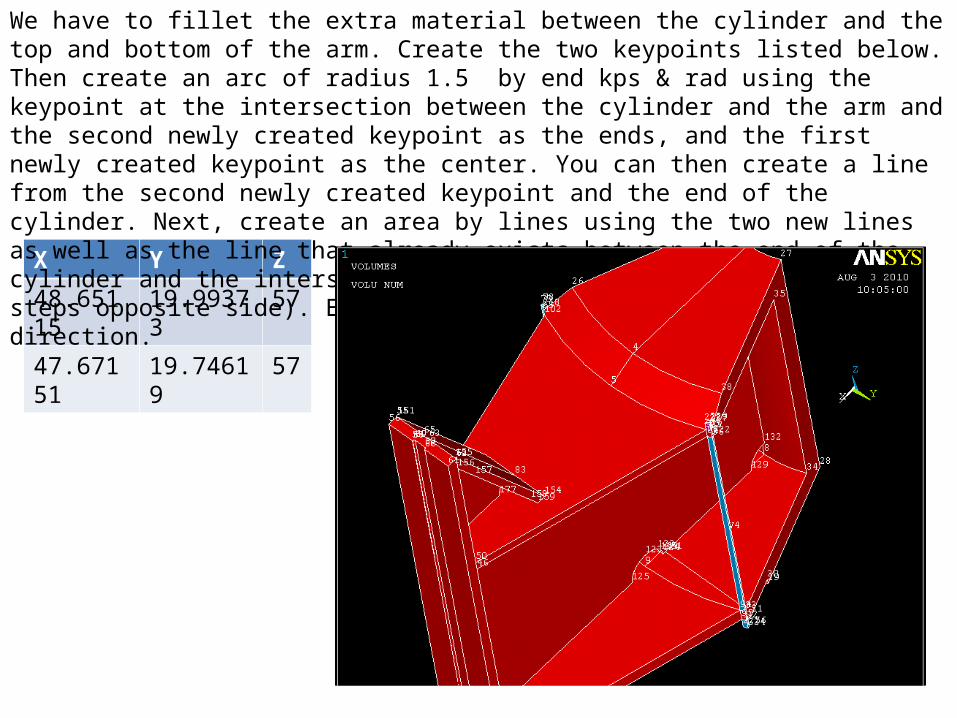
X Y Z
48.65115 -19.99373 57
47.67151 -19.74619 57
We have to fillet the extra material between the cylinder and the top and bottom of the arm. Create the two keypoints listed below. Then create an arc of radius 1.5 by end kps & rad using the keypoint at the intersection between the cylinder and the arm and the second newly created keypoint as the ends, and the first newly created keypoint as the center. You can then create a line from the second newly created keypoint and the end of the cylinder. Next, create an area by lines using the two new lines as well as the line that already exists between the end of the cylinder and the intersection of the cylidner and the arm.

Extrude this area both 4 and -57 in the z direction.
X Y Z
48.65115 19.99373 57
47.67151 19.74619 57
We have to fillet the extra material between the cylinder and the top and bottom of the arm. Create the two keypoints listed below. Then create an arc of radius 1.5 by end kps & rad using the keypoint at the intersection between the cylinder and the arm and the second newly created keypoint as the ends, and the first newly created keypoint as the center. You can then create a line from the second newly created keypoint and the end of the cylinder. Next, create an area by lines using the two new lines as well as the line that already exists between the end of the cylinder and the intersection of the cylidner and the arm (same steps opposite side). Extrude this area both 4 and -57 in the z direction.

Add the 5 volumes together (we have to do this to trick ANSYS).

Take the top areas of the poles you just created and extrude them -61 in the z direction.

Subtract the two newly created volumes from the larger volume. Remember, big volume first, then hit okay, then select the second two volumes, and then hit okay again. Make sure you pick the correct volumes.

Creating keypoints without creating keypoints – this is a little trick in case you forget something or mess up. We need keypoints on the mid plate of the bottom of the spider arm. So we can extrude a face downwards, and then add and subtract to create keypoints on an existing volume. First, select this face and extrude twice, both -.5 in the z direction.

Next, add one of the newly created volumes to the large volume.

Now, subtract the smaller volume from the recently modified larger volume. And when you replot you will see new keypoints at that -.5 mark.

Now, extrude that same face -.5 in the z direction, but leave it as a separate volume. Now the keypoints match up on both volumes, so the model can transfer loads properly.

Now, extrude the bottom area of the new volume -4.5 in the z direction (again to match keypoints).

Now, extrude the bottom area of the new volume -2.1875 in the z direction

Now, extrude the bottom area of the new volume -1.28125 in the z direction

Add these 4 volumes together. Don’t add it to the large volume.

Go to (Preprocessor >> Numbering Controls >> Merge Items) and select keypoints and hit okay. This will merge the keypoints that are at the same location, joining the two volumes while keeping them separate, and making for simpler geometry creation as we continue to build.

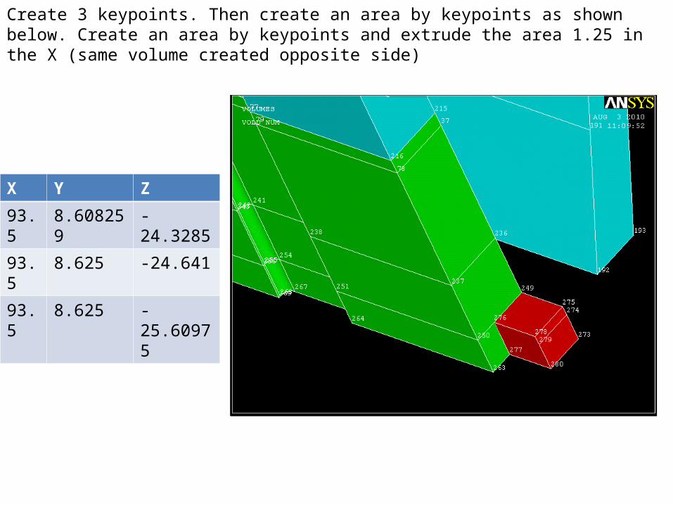
X Y Z
93.5 -8.608259 -24.3285
93.5 -8.625 -24.641
93.5 -8.625 -25.60975
Create 3 keypoints. Then create an area by keypoints as shown below.

Extrude that area 1.25 in the X direction.
X Y Z
93.5 8.608259 -24.3285
93.5 8.625 -24.641
93.5 8.625 -25.60975
Create 3 keypoints. Then create an area by keypoints as shown below. Create an area by keypoints and extrude the area 1.25 in the X (same volume created opposite side)

X Y Z
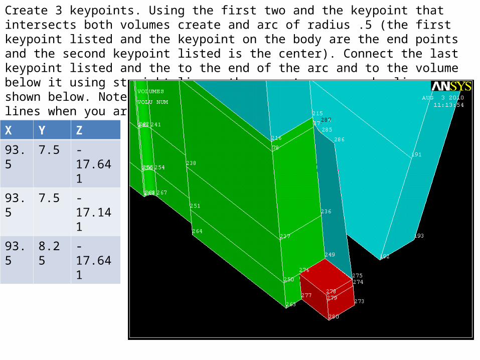
93.5 -7.5 -17.641
93.5 -7.5 -17.141
93.5 -8.25 -17.641
Create 3 keypoints. Using the first two and the keypoint that intersects both volumes create and arc of radius .5 (the first keypoint listed and the keypoint on the body are the end points and the second keypoint listed is the center). Connect the last keypoint listed and the to the end of the arc and to the volume below it using straight lines, then create an area by lines as shown below. Note: the vertical line is actually 3 lines vertical lines when you are selecting.
Create 3 keypoints. Using the first two and the keypoint that intersects both volumes create and arc of radius .5 (the first keypoint listed and the keypoint on the body are the end points and the second keypoint listed is the center). Connect the last keypoint listed and the to the end of the arc and to the volume below it using straight lines, then create an area by lines as shown below. Note: the vertical line is actually 3 lines vertical lines when you are selecting.
X Y Z
93.5 7.5 -17.641
93.5 7.5 -17.141
93.5 8.25 -17.641
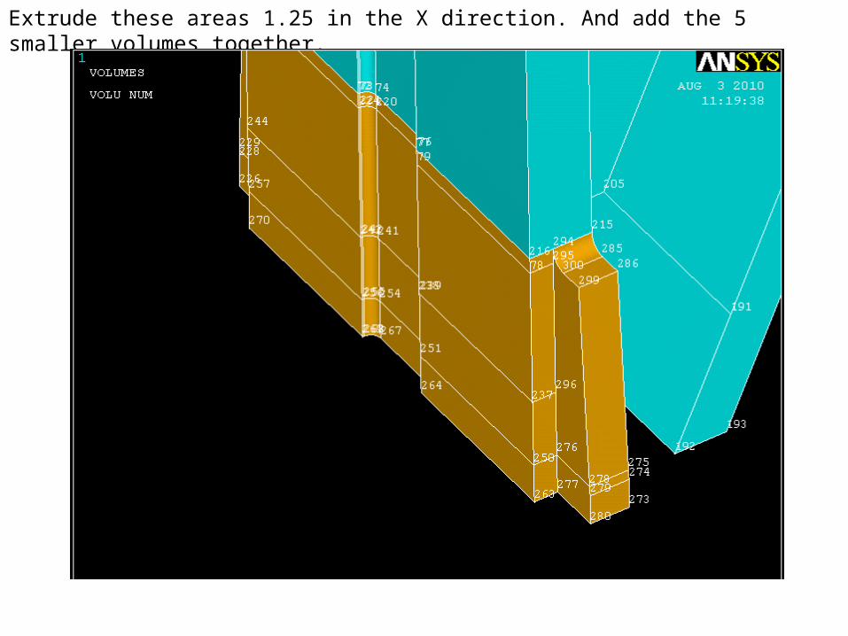
Extrude these areas 1.25 in the X direction. And add the 5 smaller volumes together.
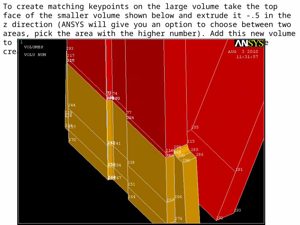
To create matching keypoints on the large volume take the top face of the smaller volume shown below and extrude it -.5 in the z direction (ANSYS will give you an option to choose between two areas, pick the area with the higher number). Add this new volume to the large volume (be careful not to select the volume we created in the previous step).

Select the bottom face of the recently modified large volume and extrude it .5 in the z direction. Then subtract the newly created volume from the large one. As you will see your new keypoints will be there.
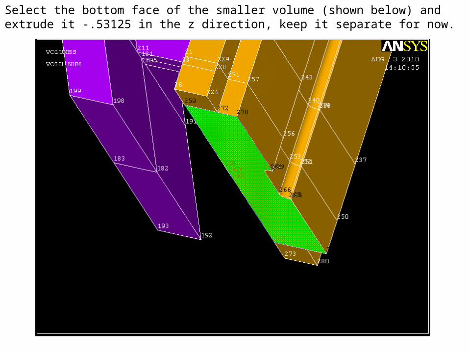
Select the bottom face of the smaller volume (shown below) and extrude it -.53125 in the z direction, keep it separate for now.

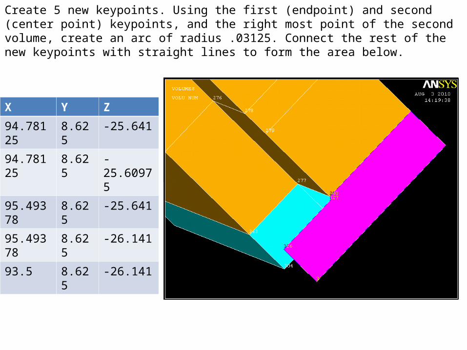
Create 5 new keypoints. Using the first (endpoint) and second (center point) keypoints, and the right most point of the second volume, create an arc of radius .03125. Connect the rest of the new keypoints with straight lines to form the area below.
X Y Z
94.78125 -8.625 -25.641
94.78125 -8.625 -25.60975
95.49378 -8.625 -25.641
95.49378 -8.625 -26.141
93.5 -8.625 -26.141

Extrude this area 1.625 in the Y direction
Create 5 new keypoints. Using the first (endpoint) and second (center point) keypoints, and the right most point of the second volume, create an arc of radius .03125. Connect the rest of the new keypoints with straight lines to form the area below.
X Y Z
94.78125 8.625 -25.641
94.78125 8.625 -25.60975
95.49378 8.625 -25.641
95.49378 8.625 -26.141
93.5 8.625 -26.141
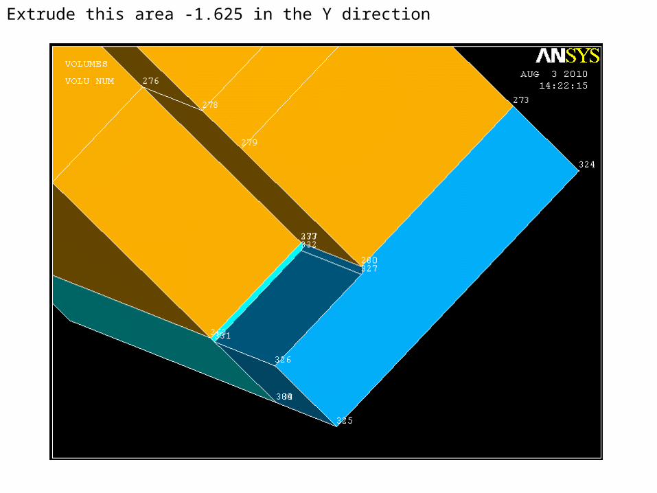
Extrude this area -1.625 in the Y direction

X Y Z
95.875 -8.875 -26.3129
95.89063 -8.875 -26.3285
95.89063 -8.875 -26.3129
96.05 -8.875 -26.3285
96.05 -8.875 -26.841
95.49378 -8.875 -26.841
95.49378 -8.875 -26.241
95.875 -8.875 -26.241
Create 8 new keypoints. The first three are used for an arc of radius .015625 (the first two are the endpoints and the third is the center point. Connect the rest with straight lines as shown below and create an area by lines as shown below.

Extrude this area .25 in the y direction

Extrude the rightmost area of the new volume .5 in the y direction
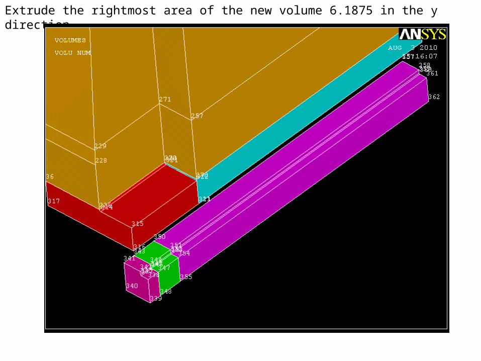
Extrude the rightmost area of the new volume 6.1875 in the y direction

Extrude the rightmost area of the new volume .5 in the y direction

Add those four new areas together

X Y Z
95.875 8.875 -26.3129
95.89063 8.875 -26.3285
95.89063 8.875 -26.3129
96.05 8.875 -26.3285
96.05 8.875 -26.841
95.49378 8.875 -26.841
95.49378 8.875 -26.241
95.875 8.875 -26.241
Create 8 new keypoints. The first three are used for an arc of radius .015625 (the first two are the endpoints and the third is the center point. Connect the rest with straight lines as shown below and create an area by lines as shown below.

Extrude this area -.25 in the y direction

Extrude the leftmost area -. 5 in the y direction
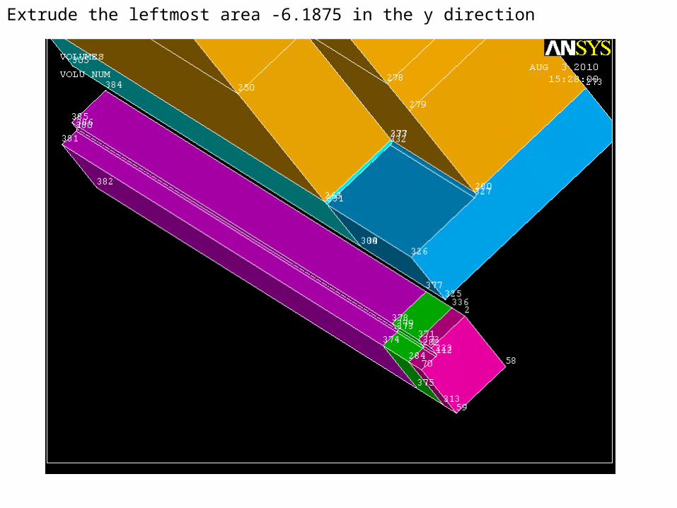
Extrude the leftmost area -6.1875 in the y direction

Extrude the leftmost area -. 5 in the y direction

Add those four new areas together

Select the front faces of the two new volumes, and extrude them .45 in the x direction.

Select the front faces of the new volumes, and extrude them .45 in the x direction again (we are creating keypoints to be used for the model with the blocks later).

Select the front faces of the new volumes, and extrude them .05 in the x direction again (we are creating keypoints to be used for the model with the blocks later).

Add the 12 new volumes on each side together. To reorder your volume numbers go to (Preprocessor >> Numbering Controls >> Compress Numbers >> Volumes)

Extrude the eight highlighted faces shown below by .1 in the z direction. (Keypoint numbering has been turned off for now (Plot Controls >> Numbering))

Extrude the three highlighted faces shown below by -.1 in the z direction.
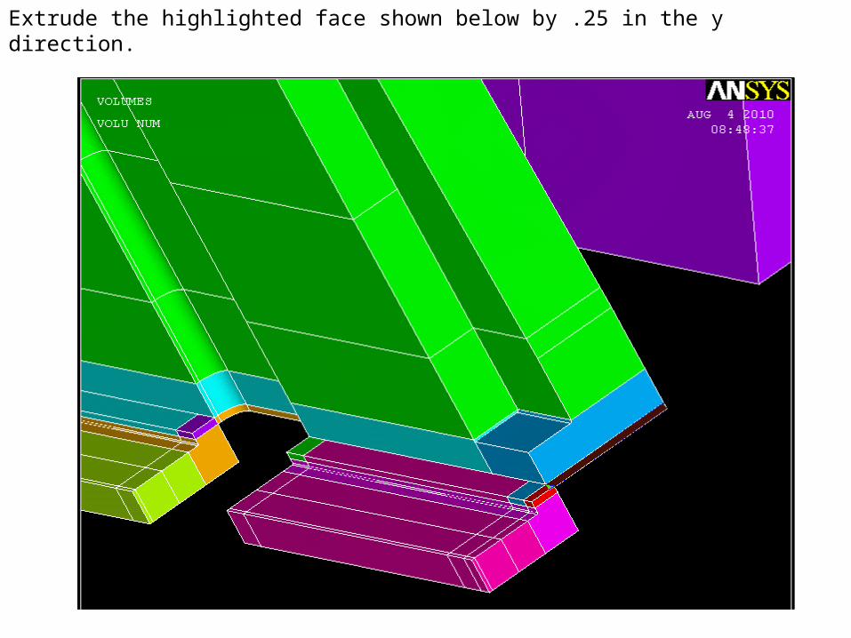
Extrude the highlighted face shown below by .25 in the y direction.

Extrude the highlighted face shown below by -.25 in the y direction.

Add all 13 of the thin volumes you just created along with the three larger volumes you created before

Extrude the five highlighted faces shown below -.6 in the Z direction and add the volumes together

To create the corresponding keypoints, extrude the highlighted faces by 1.875 in the y direction

And add them to their respective volumes (you will see the new lines and keypoints on the old volumes)

To create the corresponding keypoints, extrude the highlighted faces by -1.875 in the y direction

And add them to their respective volumes (you will see the new lines and keypoints on the old volumes)

X Y Z
98.25 -8.875 -26.141
Create one new keypoint and connect it with two straight lines to the rest of the model as shown below.

X Y Z
98.25 8.875 -26.141
Create one new keypoint and connect it with two straight lines to the rest of the model as shown below.

Create an area by lines. Remember the long lines on the left and right are made up of multiple lines – be sure to select them all.

Extrude the 3 highlighted areas by -.7 in the z direction

Add the 4 newest volumes together

Extrude all of the bottom faces -1.55 in the z direction. There are 48 of them, make sure you select the correct ones.

Add all of the new 48 faces together to create 1 volume – doing this in several steps makes it easier on the eyes. Also, clicking and dragging until the right piece is highlighted will help you select.
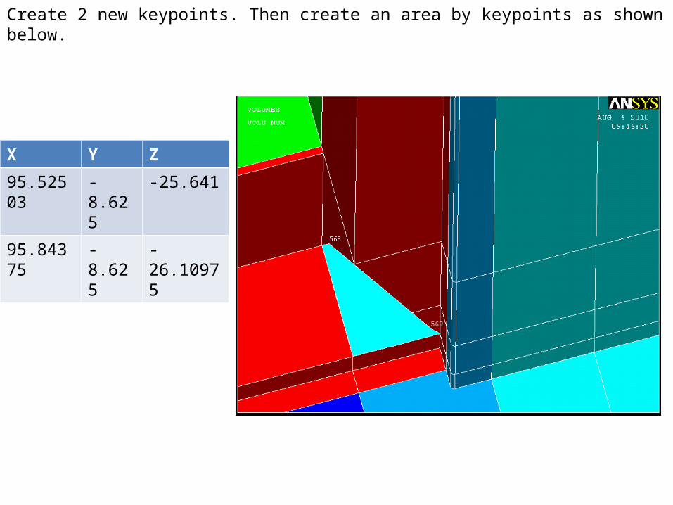
X Y Z
95.52503 -8.625 -25.641
95.84375 -8.625 -26.10975
Create 2 new keypoints. Then create an area by keypoints as shown below.

Extrude the area by 7.1875 in the y direction

X Y Z
95.52503 8.625 -25.641
95.84375 8.625 -26.10975
Create 2 new keypoints. Then create an area by keypoints as shown below.

Extrude the area by -7.1875 in the y direction

Create a small triangular area by keypoints as shown below

Extrude the area by -5.5625 in the Y direction

Create a small triangular area by keypoints as shown below

Extrude the area by 5.5625 in the Y direction

Add the 4 new areas to the base area.

Merge your keypoints (Preprocessor >> Numbering Controls >> Merge Items >> Keypoints) as well as compress your volume and keypoint numbers (Numbering Controls >> Compress Items)

Switch to a cylindrical coordinate system, by typing “csys,1” in the command line (“csys,0” will bring back cartesian coordinates). Now, we want to create full symmetry, so go to (Modeling >> Copy >> Volumes) hit pick all, and type 8 in the number of copies box, as well as 45 in the Y direction because we want a full 360 model from an 8th model.

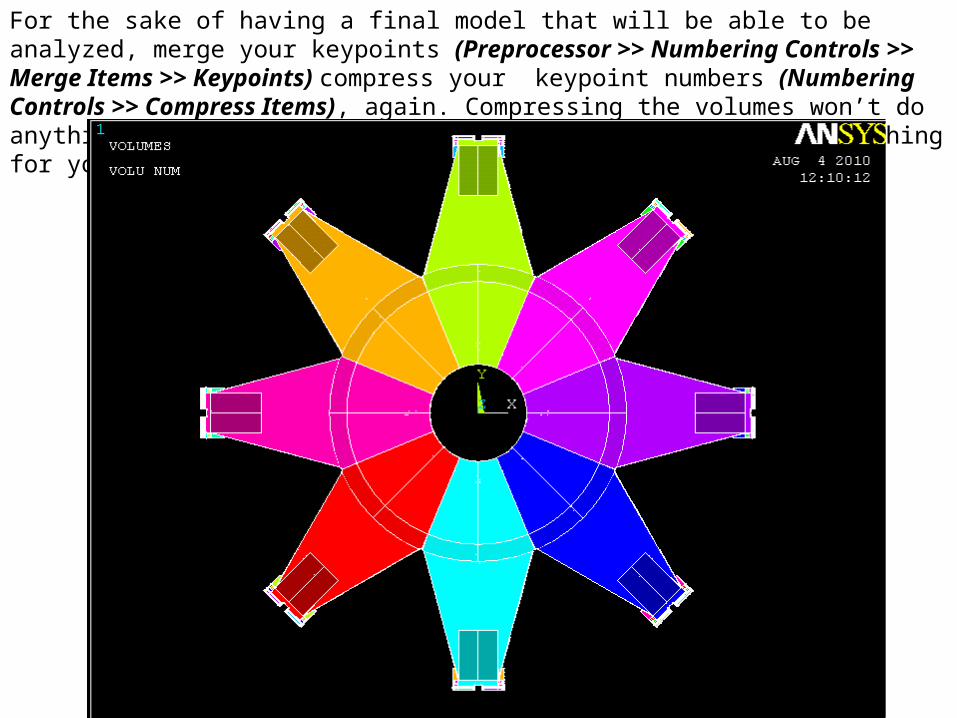
For the sake of having a final model that will be able to be analyzed, merge your keypoints (Preprocessor >> Numbering Controls >> Merge Items >> Keypoints) compress your keypoint numbers (Numbering Controls >> Compress Items), again. Compressing the volumes won’t do anything this time because ANSYS automatically created everything for you.

Fin.