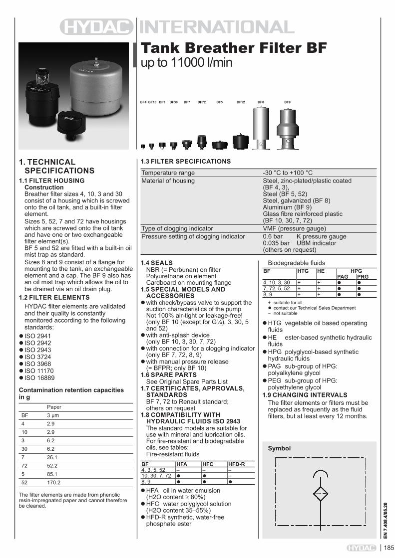
BF4 BF10 BF3 BF30 BF7 BF72 BF5 BF52 BF8 BF9
12
185 EN 7.408.4/05.20 Tank Breather Filter BF up to 11000 l/min 1. TECHNICAL SPECIFICATIONS 1.1 FILTER HOUSING Construction Breather filter sizes 4, 10, 3 and 30 consist of a housing which is screwed onto the oil tank, and a built-in filter element. Sizes 5, 52, 7 and 72 have housings which are screwed onto the oil tank and have one or two exchangeable filter element(s). BF 5 and 52 are fitted with a built-in oil mist trap as standard. Sizes 8 and 9 consist of a flange for mounting to the tank, an exchangeable element and a cap. The BF 9 also has an oil mist trap which allows the oil to be drained via an oil drain plug. 1.2 FILTER ELEMENTS HYDAC filter elements are validated and their quality is constantly monitored according to the following standards: ISO 2941 ISO 2942 ISO 2943 ISO 3724 ISO 3968 ISO 11170 ISO 16889 Contamination retention capacities in g Paper BF 3 µm 4 2.9 10 2.9 3 6.2 30 6.2 7 26.1 72 52.2 5 85.1 52 170.2 The filter elements are made from phenolic resin-impregnated paper and cannot therefore be cleaned. 1.4 SEALS NBR (= Perbunan) on filter Polyurethane on element Cardboard on mounting flange 1.5 SPECIAL MODELS AND ACCESSORIES with check/bypass valve to support the suction characteristics of the pump Not 100% air-tight or leakage-free! (only BF 10 (except for G¼), 3, 30, 5 and 52) with anti-splash device (only BF 10, 3, 30, 7, 72) with connection for a clogging indicator (only BF 7, 72, 8, 9) with manual pressure release (= BFPR; only BF 10) 1.6 SPARE PARTS See Original Spare Parts List 1.7 CERTIFICATES, APPROVALS, STANDARDS BF 7, 72 to Renault standard; others on request 1.8 COMPATIBILITY WITH HYDRAULIC FLUIDS ISO 2943 The standard models are suitable for use with mineral and lubrication oils. For fire-resistant and biodegradable oils, see tables: Fire-resistant fluids BF HFA HFC HFD-R 4, 3, 5, 52 – – – 10, 30, 7, 72 – 8, 9 HFA oil in water emulsion (H2O content ≥ 80%) HFC water polyglycol solution (H2O content 35–55%) HFD-R synthetic, water-free phosphate ester 1.3 FILTER SPECIFICATIONS Temperature range -30 °C to +100 °C Material of housing Steel, zinc-plated/plastic coated (BF 4, 3), Steel (BF 5, 52) Steel, galvanized (BF 8) Aluminium (BF 9) Glass fibre reinforced plastic (BF 10, 30, 7, 72) Type of clogging indicator VMF (pressure gauge) Pressure setting of clogging indicator 0.6 bar K pressure gauge 0.035 bar UBM indicator (others on request) BF4 EN 7.408.4/05.20 Biodegradable fluids BF HTG HE HPG PAG PRG 4, 10, 3, 30 + + 7, 72, 5, 52 + + 8, 9 + + + suitable for all contact our Technical Sales Department – not suitable HTG vegetable oil based operating fluids HE ester-based synthetic hydraulic fluids HPG polyglycol-based synthetic hydraulic fluids PAG sub-group of HPG: polyalkylene glycol PEG sub-group of HPG: polyethylene glycol 1.9 CHANGING INTERVALS The filter elements or filters must be replaced as frequently as the fluid filters, but at least every 12 months. Symbol BF10 BF3 BF30 BF7 BF72 BF5 BF52 BF8 BF9
Transcript of BF4 BF10 BF3 BF30 BF7 BF72 BF5 BF52 BF8 BF9
185
EN 7
.408
.4/0
5.20
Tank Breather Filter BFup to 11000 l/min
1. TECHNICAL SPECIFICATIONS
1.1 FILTER HOUSINGConstruction Breather filter sizes 4, 10, 3 and 30 consist of a housing which is screwed onto the oil tank, and a built-in filter element.Sizes 5, 52, 7 and 72 have housings which are screwed onto the oil tank and have one or two exchangeable filter element(s). BF 5 and 52 are fitted with a built-in oil mist trap as standard.Sizes 8 and 9 consist of a flange for mounting to the tank, an exchangeable element and a cap. The BF 9 also has an oil mist trap which allows the oil to be drained via an oil drain plug.
1.2 FILTER ELEMENTSHYDAC filter elements are validated and their quality is constantly monitored according to the following standards:
ISO 2941ISO 2942ISO 2943ISO 3724ISO 3968ISO 11170ISO 16889
Contamination retention capacities in g
PaperBF 3 µm4 2.910 2.93 6.230 6.27 26.172 52.25 85.152 170.2
The filter elements are made from phenolic resin-impregnated paper and cannot therefore be cleaned.
1.4 SEALSNBR (= Perbunan) on filter Polyurethane on element Cardboard on mounting flange
1.5 SPECIAL MODELS AND ACCESSORIES
with check/bypass valve to support the suction characteristics of the pump Not 100% air-tight or leakage-free! (only BF 10 (except for G¼), 3, 30, 5 and 52)
with anti-splash device (only BF 10, 3, 30, 7, 72)
with connection for a clogging indicator (only BF 7, 72, 8, 9)
with manual pressure release (= BFPR; only BF 10)
1.6 SPARE PARTSSee Original Spare Parts List
1.7 CERTIFICATES, APPROVALS, STANDARDSBF 7, 72 to Renault standard; others on request
1.8 COMPATIBILITY WITH HYDRAULIC FLUIDS ISO 2943The standard models are suitable for use with mineral and lubrication oils. For fire-resistant and biodegradable oils, see tables:Fire-resistant fluids
BF HFA HFC HFD-R4, 3, 5, 52 – – –10, 30, 7, 72 –8, 9
HFA oil in water emulsion (H2O content ≥ 80%)
HFC water polyglycol solution (H2O content 35–55%)
HFD-R synthetic, water-free phosphate ester
1.3 FILTER SPECIFICATIONS
Temperature range -30 °C to +100 °C Material of housing Steel, zinc-plated/plastic coated (BF 4, 3), Steel (BF 5, 52) Steel, galvanized (BF 8) Aluminium (BF 9) Glass fibre reinforced plastic (BF 10, 30, 7, 72) Type of clogging indicator VMF (pressure gauge) Pressure setting of clogging indicator 0.6 bar K pressure gauge 0.035 bar UBM indicator (others on request)
BF4
EN 7
.408
.4/0
5.20
Biodegradable fluidsBF HTG HE HPG
PAG PRG4, 10, 3, 30 + + 7, 72, 5, 52 + + 8, 9 + +
+ suitable for all contact our Technical Sales Department – not suitable
HTG vegetable oil based operating fluids
HE ester-based synthetic hydraulic fluids
HPG polyglycol-based synthetic hydraulic fluids
PAG sub-group of HPG: polyalkylene glycol
PEG sub-group of HPG: polyethylene glycol
1.9 CHANGING INTERVALSThe filter elements or filters must be replaced as frequently as the fluid filters, but at least every 12 months.
Symbol
BF10 BF3 BF30 BF7 BF72 BF5 BF52 BF8 BF9
186
EN 7
.408
.4/0
5.20
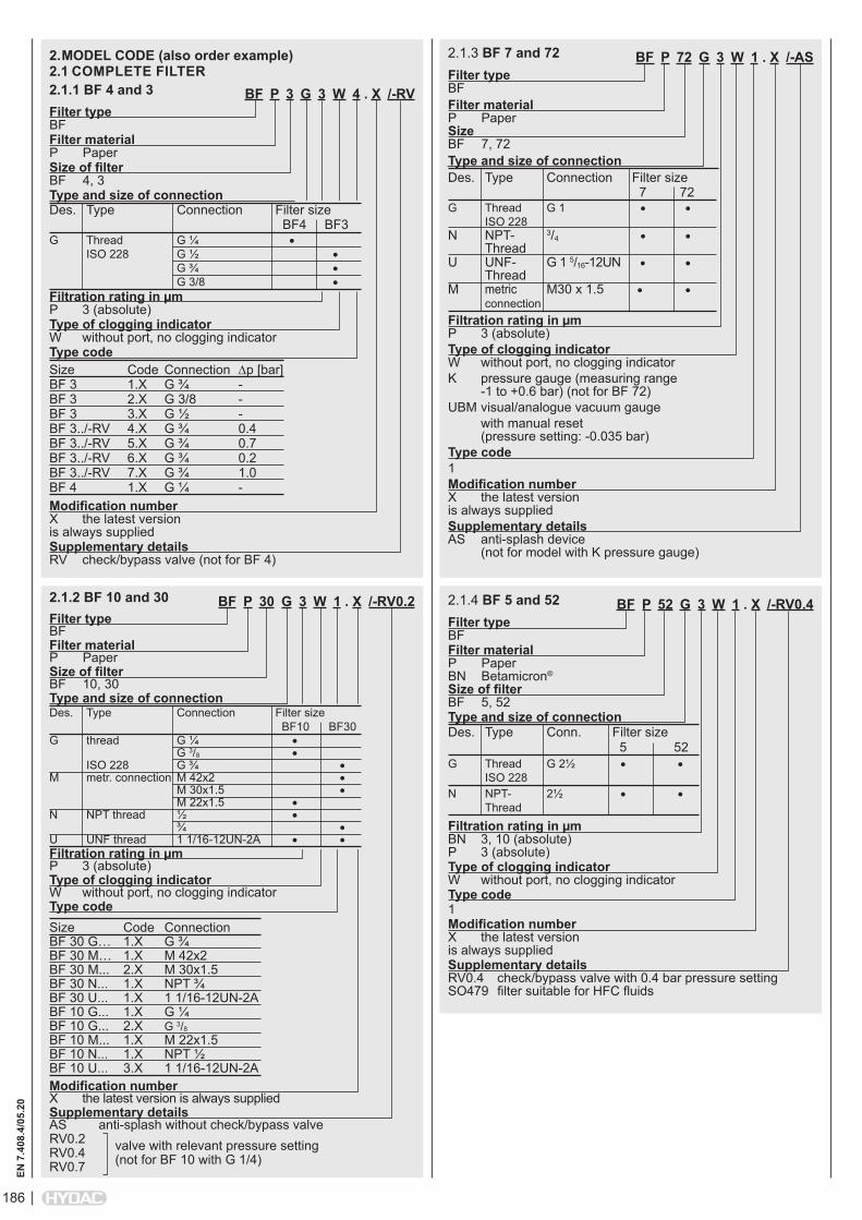
BF P 30 G 3 W 1 . X /-RV0.2Filter type BFFilter material P PaperSize of filter BF 10, 30Type and size of connectionDes. Type Connection Filter size BF10 BF30G thread G ¼ • G 3/8 • ISO 228 G ¾ •M metr. connection M 42x2 • M 30x1.5 • M 22x1.5 • N NPT thread ½ • ¾ •U UNF thread 1 1/16-12UN-2A • •Filtration rating in µm P 3 (absolute)Type of clogging indicator W without port, no clogging indicatorType code Size Code ConnectionBF 30 G… 1.X G ¾BF 30 M… 1.X M 42x2BF 30 M... 2.X M 30x1.5BF 30 N... 1.X NPT ¾BF 30 U... 1.X 1 1/16-12UN-2ABF 10 G... 1.X G ¼ BF 10 G... 2.X G 3/8
BF 10 M... 1.X M 22x1.5BF 10 N... 1.X NPT ½ BF 10 U... 3.X 1 1/16-12UN-2AModification number X the latest version is always suppliedSupplementary details AS anti-splash without check/bypass valveRV0.2RV0.4 valve with relevant pressure settingRV0.7 (not for BF 10 with G 1/4)
2. MODEL CODE (also order example)2.1 COMPLETE FILTER2.1.1 BF 4 and 3
BF P 72 G 3 W 1 . X /-ASFilter type BFFilter material P Paper Size BF 7, 72Type and size of connectionDes. Type Connection Filter size 7 72G Thread G 1 • • ISO 228N NPT- 3/4 • • ThreadU UNF- G 1 5/16-12UN • • ThreadM metric M30 x 1.5 • • connectionFiltration rating in µm P 3 (absolute)Type of clogging indicator W without port, no clogging indicatorK pressure gauge (measuring range -1 to +0.6 bar) (not for BF 72)UBM visual/analogue vacuum gauge with manual reset (pressure setting: -0.035 bar)Type code 1Modification number X the latest version is always suppliedSupplementary details AS anti-splash device (not for model with K pressure gauge)
2.1.3 BF 7 and 72
BF P 3 G 3 W 4 . X /-RVFilter type BFFilter material P PaperSize of filter BF 4, 3Type and size of connectionDes. Type Connection Filter size BF4 BF3G Thread G ¼ • ISO 228 G ½ • G ¾ • G 3/8 •Filtration rating in µm P 3 (absolute)Type of clogging indicator W without port, no clogging indicatorType code Size Code Connection ∆p [bar]BF 3 1.X G ¾ -BF 3 2.X G 3/8 -BF 3 3.X G ½ -BF 3../-RV 4.X G ¾ 0.4BF 3../-RV 5.X G ¾ 0.7BF 3../-RV 6.X G ¾ 0.2BF 3../-RV 7.X G ¾ 1.0BF 4 1.X G ¼ -Modification number X the latest version is always suppliedSupplementary details RV check/bypass valve (not for BF 4)
BF P 52 G 3 W 1 . X /-RV0.4Filter type BFFilter material P Paper BN Betamicron® Size of filter BF 5, 52Type and size of connectionDes. Type Conn. Filter size 5 52G Thread G 2½ • • ISO 228N NPT- 2½ • • ThreadFiltration rating in µm BN 3, 10 (absolute) P 3 (absolute)Type of clogging indicator W without port, no clogging indicatorType code 1Modification number X the latest version is always suppliedSupplementary details RV0.4 check/bypass valve with 0.4 bar pressure setting SO479 filter suitable for HFC fluids
2.1.4 BF 5 and 522.1.2 BF 10 and 30
187
EN 7
.408
.4/0
5.20
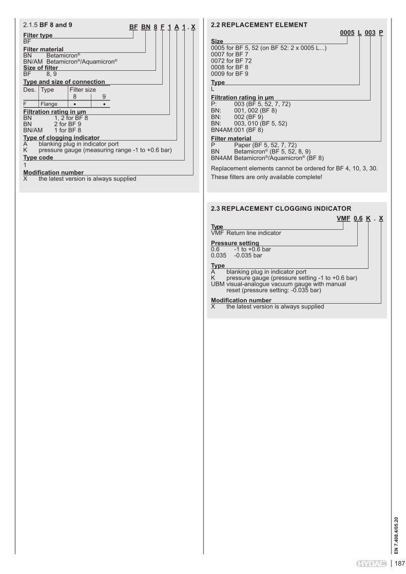
BF BN 8 F 1 A 1 . XFilter type BFFilter material BN Betamicron® BN/AM Betamicron®/Aquamicron® Size of filter BF 8, 9Type and size of connectionDes. Type Filter size 8 9F Flange • •Filtration rating in µm BN 1, 2 for BF 8 BN 2 for BF 9 BN/AM 1 for BF 8Type of clogging indicator A blanking plug in indicator port K pressure gauge (measuring range -1 to +0.6 bar)Type code 1Modification number X the latest version is always supplied
2.1.5 BF 8 and 90005 L 003 P
Size 0005 for BF 5, 52 (on BF 52: 2 x 0005 L...) 0007 for BF 7 0072 for BF 72 0008 for BF 8 0009 for BF 9Type LFiltration rating in µm P: 003 (BF 5, 52, 7, 72) BN: 001, 002 (BF 8) BN: 002 (BF 9) BN: 003, 010 (BF 5, 52) BN4AM: 001 (BF 8)Filter material P Paper (BF 5, 52, 7, 72) BN Betamicron® (BF 5, 52, 8, 9) BN4AM Betamicron®/Aquamicron® (BF 8)Replacement elements cannot be ordered for BF 4, 10, 3, 30.These filters are only available complete!
2.2 REPLACEMENT ELEMENT
VMF 0.6 K . XType VMF Return line indicatorPressure setting 0.6 -1 to +0.6 bar 0.035 -0.035 barType A blanking plug in indicator port K pressure gauge (pressure setting -1 to +0.6 bar) UBM visual-analogue vacuum gauge with manual reset (pressure setting: -0.035 bar)Modification number X the latest version is always supplied
2.3 REPLACEMENT CLOGGING INDICATOR
188
EN 7
.408
.4/0
5.20
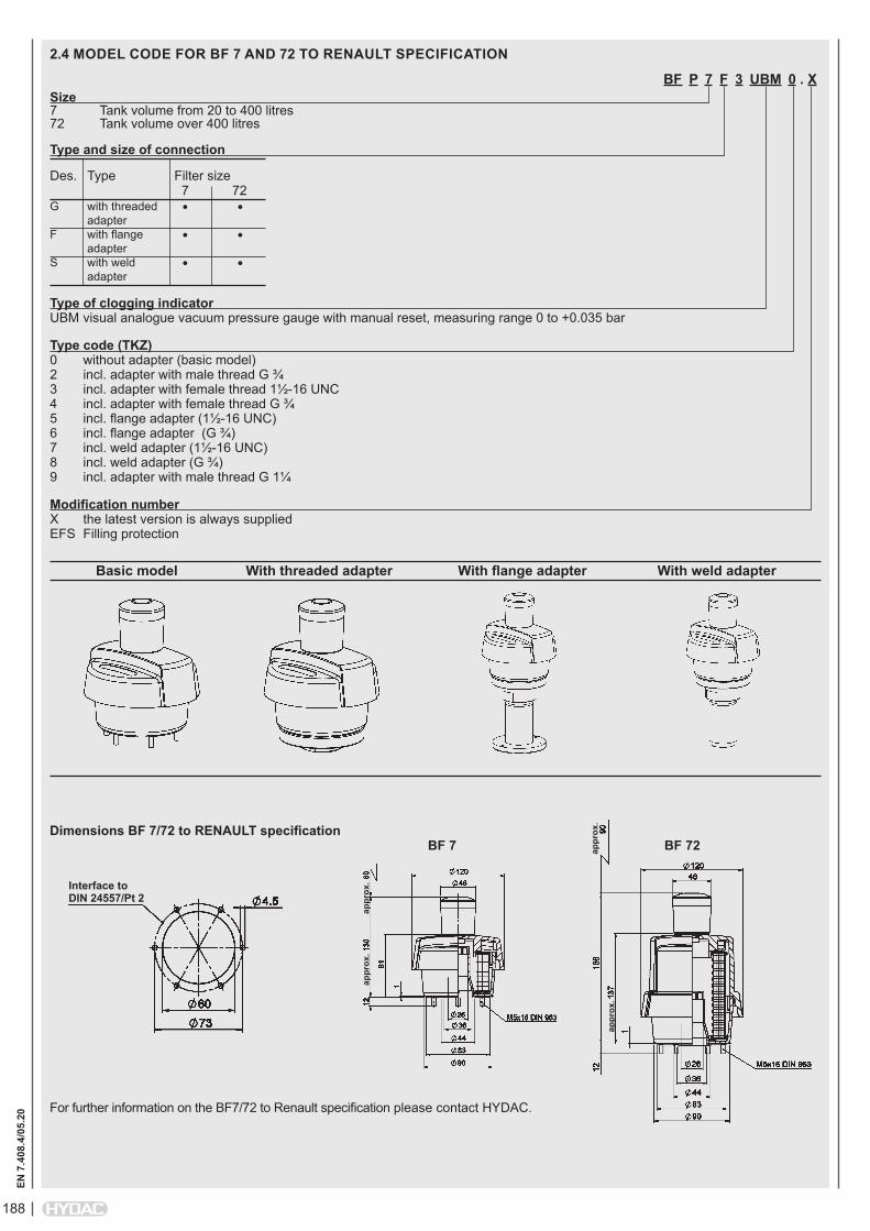
BF P 7 F 3 UBM 0 . XSize 7 Tank volume from 20 to 400 litres 72 Tank volume over 400 litres
Type and size of connection
Des. Type Filter size 7 72G with threaded • • adapter F with flange • • adapter S with weld • • adapter
Type of clogging indicator UBM visual analogue vacuum pressure gauge with manual reset, measuring range 0 to +0.035 bar
Type code (TKZ) 0 without adapter (basic model) 2 incl. adapter with male thread G ¾ 3 incl. adapter with female thread 1½-16 UNC 4 incl. adapter with female thread G ¾ 5 incl. flange adapter (1½-16 UNC) 6 incl. flange adapter (G ¾) 7 incl. weld adapter (1½-16 UNC) 8 incl. weld adapter (G ¾) 9 incl. adapter with male thread G 1¼
Modification number X the latest version is always supplied EFS Filling protection
2.4 MODEL CODE FOR BF 7 AND 72 TO RENAULT SPECIFICATION
Basic model With threaded adapter With flange adapter With weld adapter
Dimensions BF 7/72 to RENAULT specification
For further information on the BF7/72 to Renault specification please contact HYDAC.
BF 7 BF 72
Interface to DIN 24557/Pt 2
appr
ox.
appr
ox.
appr
ox.
appr
ox.
189
EN 7
.408
.4/0
5.20
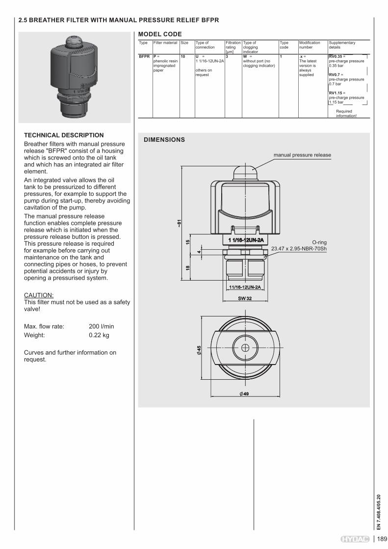
2.5 BREATHER FILTER WITH MANUAL PRESSURE RELIEF BFPR
MODEL CODEType Filter material Size Type of
connectionFiltration rating [µm]
Type of clogging indicator
Type code
Modification number
Supplementary details
BFPR P = phenolic resin impregnated paper
10 U = 1 1/16-12UN-2A others on request
3 W = without port (no clogging indicator)
1 .x = The latest version is always supplied
RV0.35 = pre-charge pressure 0.35 bar RV0.7 = pre-charge pressure 0.7 bar RV1.15 = pre-charge pressure 1.15 bar Required information!
TECHNICAL DESCRIPTIONBreather filters with manual pressure release "BFPR" consist of a housing which is screwed onto the oil tank and which has an integrated air filter element. An integrated valve allows the oil tank to be pressurized to different pressures, for example to support the pump during start-up, thereby avoiding cavitation of the pump.The manual pressure release function enables complete pressure release which is initiated when the pressure release button is pressed. This pressure release is required for example before carrying out maintenance on the tank and connecting pipes or hoses, to prevent potential accidents or injury by opening a pressurised system.
CAUTION: This filter must not be used as a safety valve!
Max. flow rate: 200 l/minWeight: 0.22 kg
Curves and further information on request.
DIMENSIONS
manual pressure release
O-ring 23.47 x 2.95-NBR-70Sh
190
EN 7
.408
.4/0
5.20
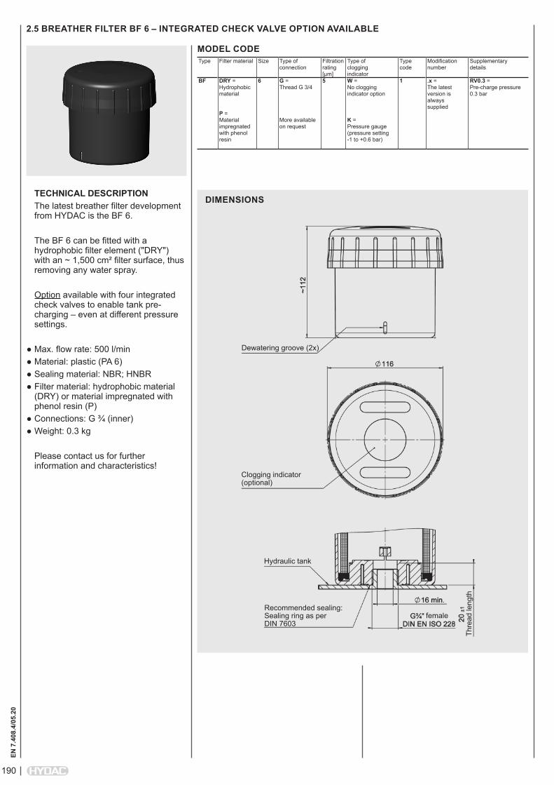
2.5 BREATHER FILTER BF 6 – INTEGRATED CHECK VALVE OPTION AVAILABLE
MODEL CODEType Filter material Size Type of
connectionFiltration rating [µm]
Type of clogging indicator
Type code
Modification number
Supplementary details
BF DRY = Hydrophobic material P = Material impregnated with phenol resin
6 G = Thread G 3/4 More available on request
5 W = No clogging indicator option K = Pressure gauge (pressure setting -1 to +0.6 bar)
1 .x = The latest version is always supplied
RV0.3 = Pre-charge pressure 0.3 bar
TECHNICAL DESCRIPTIONThe latest breather filter development from HYDAC is the BF 6.
The BF 6 can be fitted with a hydrophobic filter element ("DRY") with an ~ 1,500 cm² filter surface, thus removing any water spray.
Option available with four integrated check valves to enable tank pre-charging – even at different pressure settings.
● Max. flow rate: 500 l/min● Material: plastic (PA 6)● Sealing material: NBR; HNBR● Filter material: hydrophobic material
(DRY) or material impregnated with phenol resin (P)
● Connections: G ¾ (inner)● Weight: 0.3 kg
Please contact us for further information and characteristics!
DIMENSIONS
Dewatering groove (2x)
Clogging indicator (optional)
Hydraulic tank
Recommended sealing: Sealing ring as per DIN 7603
female
Thre
ad le
ngth
191
EN 7
.408
.4/0
5.20
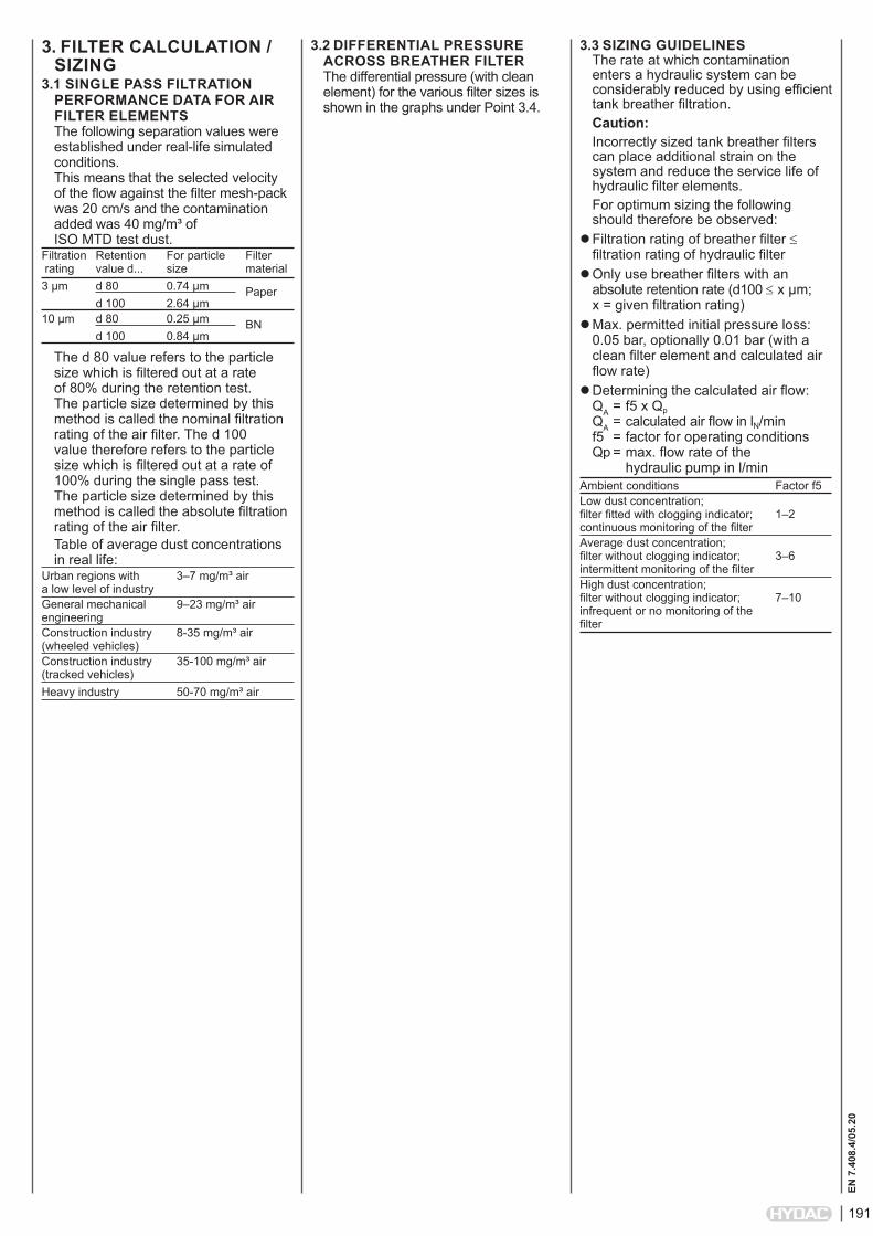
3. FILTER CALCULATION / SIZING
3.1 SINGLE PASS FILTRATION PERFORMANCE DATA FOR AIR FILTER ELEMENTSThe following separation values were established under real-life simulated conditions. This means that the selected velocity of the flow against the filter mesh-pack was 20 cm/s and the contamination added was 40 mg/m³ of ISO MTD test dust.
Filtration Retention For particle Filter rating value d... size material3 µm d 80 0.74 µm Paper d 100 2.64 µm 10 µm d 80 0.25 µm BN d 100 0.84 µm
The d 80 value refers to the particle size which is filtered out at a rate of 80% during the retention test. The particle size determined by this method is called the nominal filtration rating of the air filter. The d 100 value therefore refers to the particle size which is filtered out at a rate of 100% during the single pass test. The particle size determined by this method is called the absolute filtration rating of the air filter.Table of average dust concentrations in real life:
Urban regions with 3–7 mg/m³ air a low level of industryGeneral mechanical 9–23 mg/m³ air engineeringConstruction industry 8-35 mg/m³ air (wheeled vehicles)Construction industry 35-100 mg/m³ air (tracked vehicles)Heavy industry 50-70 mg/m³ air
3.3 SIZING GUIDELINES The rate at which contamination enters a hydraulic system can be considerably reduced by using efficient tank breather filtration.Caution:Incorrectly sized tank breather filters can place additional strain on the system and reduce the service life of hydraulic filter elements.For optimum sizing the following should therefore be observed:
Filtration rating of breather filter ≤ filtration rating of hydraulic filter
Only use breather filters with an absolute retention rate (d100 ≤ x µm; x = given filtration rating)
Max. permitted initial pressure loss: 0.05 bar, optionally 0.01 bar (with a clean filter element and calculated air flow rate)
Determining the calculated air flow: QA = f5 x Qp QA = calculated air flow in lN/min f5 = factor for operating conditions Qp = max. flow rate of the hydraulic pump in l/min
Ambient conditions Factor f5Low dust concentration; filter fitted with clogging indicator; 1–2 continuous monitoring of the filterAverage dust concentration; filter without clogging indicator; 3–6 intermittent monitoring of the filterHigh dust concentration; filter without clogging indicator; 7–10 infrequent or no monitoring of the filter
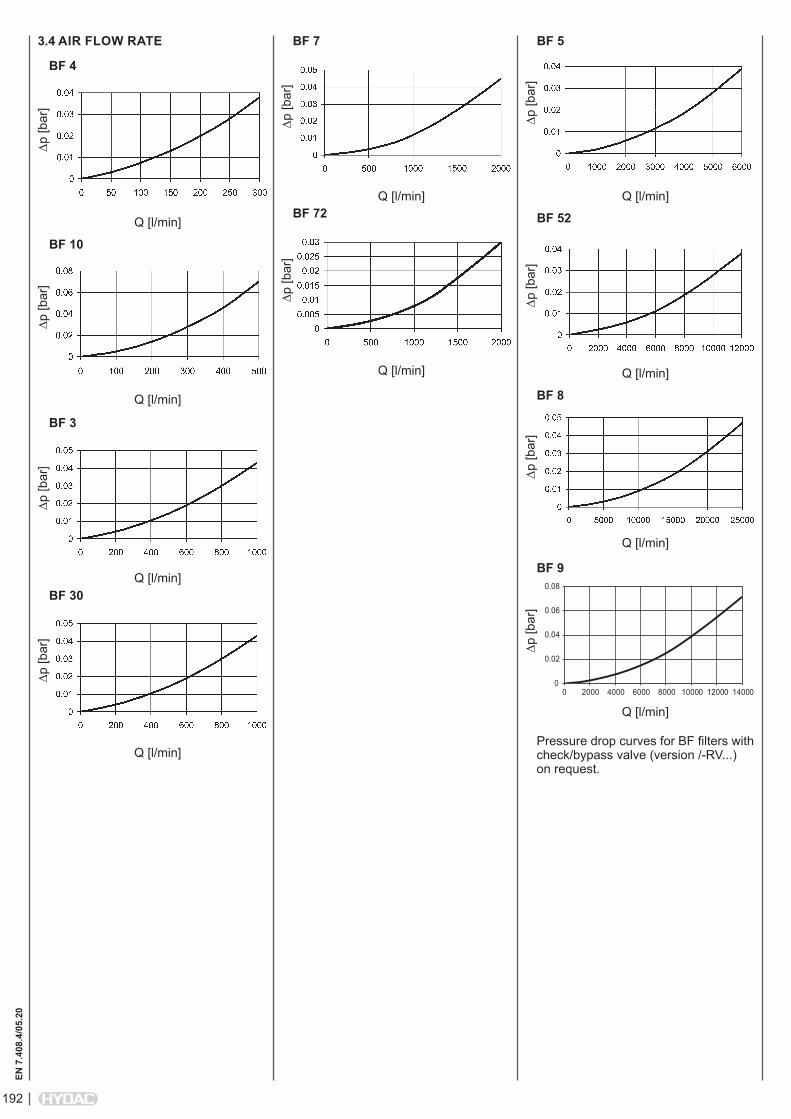
3.2 DIFFERENTIAL PRESSURE ACROSS BREATHER FILTERThe differential pressure (with clean element) for the various filter sizes is shown in the graphs under Point 3.4.
192
EN 7
.408
.4/0
5.20
∆p [b
ar]
Q [l/min]
BF 4
∆p [b
ar]
Q [l/min]
BF 10
3.4 AIR FLOW RATE∆p
[bar
]
Q [l/min]
BF 30
∆p [b
ar]
BF 3
Q [l/min]
∆p [b
ar]
Q [l/min]
BF 7
∆p [b
ar]
Q [l/min]
BF 72
∆p [b
ar]
Q [l/min]
BF 5
∆p [b
ar]
Q [l/min]
BF 52
∆p [b
ar]
BF 8
Q [l/min]
Pressure drop curves for BF filters with check/bypass valve (version /-RV...) on request.
∆p [b
ar]
Q [l/min]
BF 9
0
0.02
0.04
0.06
0.08
0 2000 4000 6000 8000 10000 12000 14000
193
EN 7
.408
.4/0
5.20
BF 4
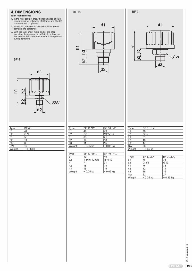
BF 104. DIMENSIONS BF 3
Type BF 4...d1 44d2 G ¼ h1 58h2 14h3 8SW 17Weight ~ 0.08 kg
Tank requirements1. In the filter contact area, the tank flange should
have a maximum flatness of 0.2 mm and Ra 3.2 µm maximum roughness.
2. In addition, the contact area should be free of damage and scratches.
3. Both the tank sheet metal and/or the filter mounting flange must be sufficiently robust so that neither deform when the seal is compressed during tightening.
Type BF 3...1.Xd1 76d2 G ¾ h1 81h2 16h3 17SW 36Weight ~ 0.35 kg
Type BF 3...2.X BF 3...3.Xd1 76 76d2 G 3/8 G ½ h1 76 78h2 12 14h3 16 16SW 22 27Weight ~ 0.35 kg ~ 0.35 kg
Type BF 10 "G"... BF 10 "M"...d1 49 49d2 G ¼ M22x1.5h1 63 71h2 14 18h3 11 15Weight ~ 0.05 kg ~ 0.05 kg
Type BF 10 "U"... BF 10 "N"...d1 49 49d2 1 1/16-12 UN NPT ½h1 71 71h2 18 18h3 15 15Weight ~ 0.05 kg ~ 0.05 kg
194
EN 7
.408
.4/0
5.20
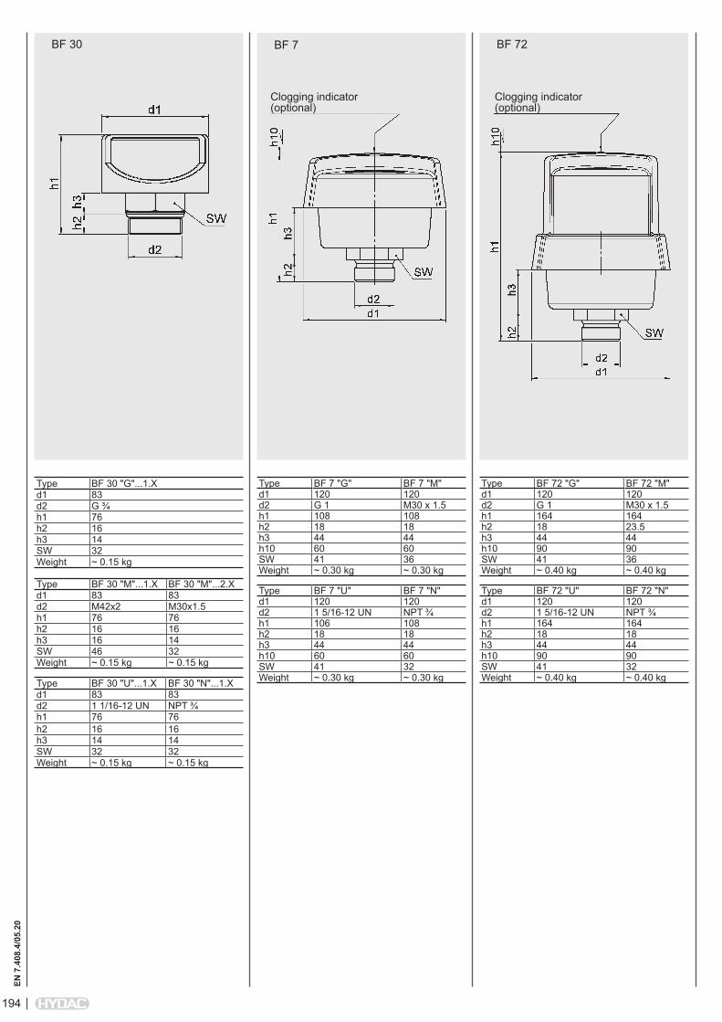
BF 30 BF 7
Type BF 7 "G" BF 7 "M"d1 120 120d2 G 1 M30 x 1.5h1 108 108h2 18 18h3 44 44h10 60 60SW 41 36Weight ~ 0.30 kg ~ 0.30 kg
Type BF 7 "U" BF 7 "N"d1 120 120d2 1 5/16-12 UN NPT ¾h1 106 108h2 18 18h3 44 44h10 60 60SW 41 32Weight ~ 0.30 kg ~ 0.30 kg
BF 72
Type BF 30 "G"...1.Xd1 83d2 G ¾ h1 76h2 16h3 14SW 32Weight ~ 0.15 kg
Type BF 30 "M"...1.X BF 30 "M"...2.Xd1 83 83d2 M42x2 M30x1.5h1 76 76h2 16 16h3 16 14SW 46 32Weight ~ 0.15 kg ~ 0.15 kg
Type BF 30 "U"...1.X BF 30 "N"...1.Xd1 83 83d2 1 1/16-12 UN NPT ¾ h1 76 76h2 16 16h3 14 14SW 32 32Weight ~ 0.15 kg ~ 0.15 kg
Type BF 72 "G" BF 72 "M"d1 120 120d2 G 1 M30 x 1.5h1 164 164h2 18 23.5h3 44 44h10 90 90SW 41 36Weight ~ 0.40 kg ~ 0.40 kg
Type BF 72 "U" BF 72 "N"d1 120 120d2 1 5/16-12 UN NPT ¾h1 164 164h2 18 18h3 44 44h10 90 90SW 41 32Weight ~ 0.40 kg ~ 0.40 kg
Clogging indicator (optional)
Clogging indicator (optional)

195
EN 7
.408
.4/0
5.20
BF 5 / BF 5...RV BF 52 / BF 52...RV BF 8
Type BF 5 "G"... BF 5 "G".../-RVd1 177 177d2 G 2½ G 2½ d4 Ø82.5 Ø89h1 103 121h2 20 +3/-5 max. 18h3 47 65h4 12 30h10 90 90Weight ~ 1.60 kg ~ 2.75 kg
Type BF 5 "N"...d1 177d2 NPT 2½d4 Ø82.5h1 103h2 –h3 47h4 12h10 90Weight ~ 1.60 kg
Type BF 8...d1 200d4 200h1 497h3 114h4 10h10 400Weight ~ 10.00 kg
Clogging indicator (optional)
Flange connection BF 8
Sealing surface Flatness: 0.2 Surface roughness: Ra 3.2
Type BF 52 "G"... BF 52 "G".../-RVd1 177 177d2 G 2½ G 2½ d4 Ø82.5 Ø89h1 188 193h2 20 +3/-5 max. 18h3 63 81h4 12 30h10 150 150Weight ~ 2.00 kg ~ 3.00 kg
Hole pattern and sealing surface, O-ring
196
EN 7
.408
.4/0
5.20
NOTEThe information in this brochure relates to the operating conditions and applications described. For applications or operating conditions not described, please contact the relevant technical department. Subject to technical modifications.
HYDAC Filtertechnik GmbH Industriegebiet D-66280 Sulzbach/Saar Tel.: 0 68 97 / 509-01 Fax: 0 68 97 / 509-300 Internet: www.hydac.com E-Mail: [email protected]
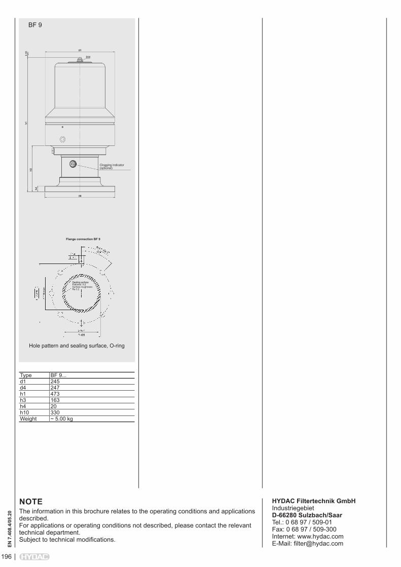
BF 9
Type BF 9...d1 245d4 247h1 473h3 163h4 20h10 330Weight ~ 5.00 kg
Clogging indicator (optional)
Flange connection BF 9
Sealing surface Flatness: 0.2 Surface roughness: Ra 3.2
Hole pattern and sealing surface, O-ring