BETACAM SP ONE-PIECE CAMCORDER (NTSC) -
20
BETACAM SP ONE-PIECE CAMCORDER (NTSC)
Transcript of BETACAM SP ONE-PIECE CAMCORDER (NTSC) -
.
BETACAM SP ONE-PIECE CAMCORDER(NTSC)
Contents
1. INTRODUCTION
2. HISTORY OF FIELD SHOOTING
2-1. Early Days of ENG
2-2. The Introduction of BetacamTM System
2-3. The Introduction of Betacam SP System
2-4. The Introduction of BVW-200 One-piece Camcorder
3. INNOVATION IN THE BVW-200/300/400
3-1. One-piece Camcorder Internal Layout
3-2. VTR Mechanical Features
3-2-1. Small drum design
3-2-2. Miniaturized tape transport mechanism
3-3. VTR Electronic Features
3-3-1. Plug-in PC board construction
3-3-2. Software servo control IC
3-3-3. Serial interface among CPU's
3-3-4. High density circuit board
3-3-5. LCD multiple displays
3.4. Camera Technical Features
3-4-1. Camera head construction
3-4-2. Advanced Sony's CCD technology
4. EASY OPERATION
4-1. Refined Ergonomics
4-2. Rain and Dust-proof Structure
4-3. Quick Start Viewfinder
4-3-1. Optical/CRT
4-3-2. Viewfinder mechanism
4-3-3. Operational facilities
4-4. Detachable Microphone
4-5. Tally Lamp
4-6. Battery for Time Code Back-up
4-7. Other Operational Facilities
4-7-1. VTR section
4-7-2. Camera section
4-7-3. Exclusive features for BVW-400
5. EASY MAINTENANCE AND ADVANCED SERVICEABILITY
6. EXCELLENT EXPANDABILITY
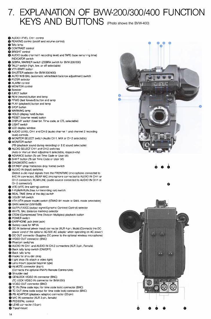
7. EXPLANATION OF BVW-200/300/400 FUNCTION KEYS AND BUTTONS
8. SPECIFICATIONS
Before delving into the technical and operational issues,
let us briefly review the history of news coverage and
Single Camera Production in the television industry.
2.2. The Introduction of Betacam System
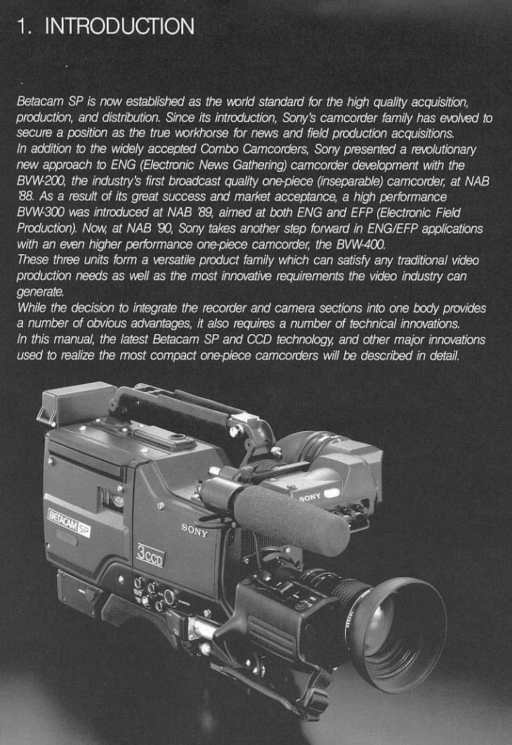
The most notable recent advance in field acquisition has
been the introduction of Betacam, half-inch analog
component recording system, and 3-chip CCD cameras.
Thanks to the advanced Betacam technology, high
performance in a smaller package was possible. The
camcorder concept that docked the camera and
recorder in a single unit was born. The BVW-1, Sony's
first Betacam camcorder, was introduced in 1982, and
then the Sony BVW-3 camcorder, introduced in 1983,
brought high quality pictures to news crews, while
weighing only approximately 10.5 kg (23 Ib 2 oz), fully
loaded.
2.1. Early Days of ENG
In the latter part of the 1970's, the first compact,
portable cameras started to appear on the market. At
about the same time, Sony's first U-matic portable
recorders for broadcast applications became available.
These two developments triggered the start of the
transition from film to video news gathering or, as it
came to be known, "Electronic News Gathering" (ENG).
To some extent this also applied to what became known
as "Electronic Field Production" (EFP).
Video overcame the fundamental drawback of 16mm
film cameras, which were originally used for news
coverage. From the actual field gathering point of view,
film cameras were convenient, particularly with respect
to size, weight, power consumption and overall simplicity
and ruggedness. However, film was and still is limited by
the over-riding disadvantage of being intrinsically a time
delayed system-in other words, processing of the film
is necessary before viewing or transmission is possible.
Video achieved the immediacy so desirable for effective
hard news coverage. Of course, this advancement was
achieved at considerable sacrifice on the part of the
news camera person. From carrying and operating a
simple, small, lightweight and rugged system, he was
saddled with a relatively bulky, complicated and more
delicate system, involving a separate camera and a
recorder with a cable.
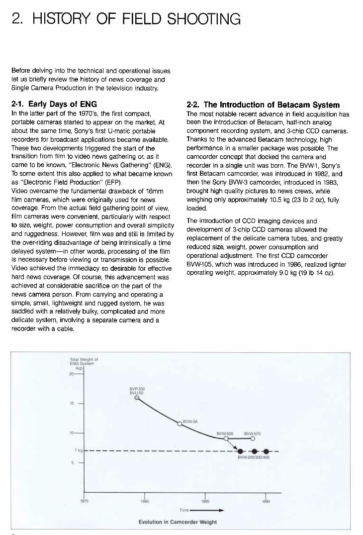
The introduction of CCD imaging devices and
development of 3-chip CCD cameras allowed the
replacement of the delicate camera tubes, and greatly
reduced size, weight, power consumption and
operational adjustment. The first CCD camcorder
BVW-105, which was introduced in 1986, realized lighter
operating weight, approximately 9.0 kg (19 Ib 14 oz).
2
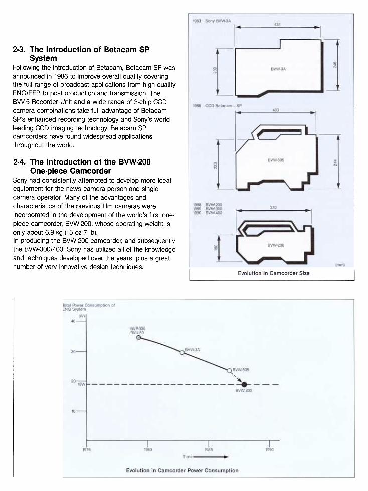
2.3. The Introduction of Betacam SP
SystemFollowing the introduction of Betacam, Betacam SP was
announced in 1986 to improve overall quality covering
the full range of broadcast applications from high quality
ENG/EFP, to post production and transmission. The
BW-5 Recorder Unit and a wide range of 3-chip CCD
camera combinations take full advantage of Betacam
SP's enhanced recording technology and Sony's world
leading CCD imaging technology. Betacam SP
camcorders have found widespread applications
throughout the world.
2.4. The Introduction of the BVW.200
One.piece Camcorder
Sony had consistently attempted to develop more ideal
equipment for the news camera person and single
camera operator. Many of the advantages and
characteristics of the previous film cameras were
incorporated in the development of the world's first one.
piece camcorder, BVW-200, whose operating weight is
only about 6.9 kg (15 oz 7 Ib).
In producing the BVW-200 camcorder, and subsequently
the BVW-300/400, Sony has utilized all of the knowledge
and techniques developed over the years, plus a great
number of very innovative design techniques.
While Betacam SP Camcorders are now widely
accepted in the broadcast and production industry, users
have consistently requested the development of more
compact and lightweight camcorders.
Considering the present ENG situation where a VTR and
a camera are used in a unified way in almost all cases,
a bold new design concept of an inseparable camcorder
was used. This enabled realization of the greatly reduced
size, weight, and power consumption. Of course, special
attention was also paid to the other critical factors such
as reliability, mobility, operational ease of use, flexibility,
and serviceability. These key design decisions were
made after close consultation between veteran ENG
crews from major international broadcast organizations
and Sony industrial designers as well as electrical and
mechanical engineers. As a result of this collaboration,
the Sony one-piece camcorder family encompasses the
majority of the recommendations from the people who
use these remarkable new tools.
.Shorter length and lower profile for better peripheral
vision
.Quick start up and improved layout for all operational
controls
.Uncompromised technical performance that fully
exploits the inherent superiority of Betacam SP
recording capability.Freedom from daily technical alignment and easy
maintenance
.Enhanced reliability
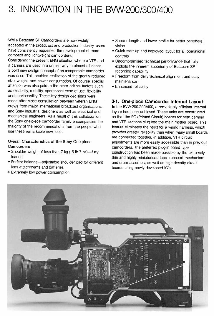
3-1. One-piece Camcorder Internal Layout
In the BVW-200/300/400, a remarkably efficient Internal
layout has been achieved. These units are constructed
so that the PC (Printed Circuit) boards for both camera
and VTR sections plug into the main mother board. This
feature eliminates the need for a wiring harness, which
provides greater reliability than when many small boards
are connected together. In addition, VTR circuit
adjustments are more easily accessible than in previous
camcorders. The preferred plug-in board type
construction has been made possible by the extremely
thin and highly miniaturised tape transport mechanism
and drum assembly, as well as high density circuit
boards using newly developed IC's.
Overall Characteristics of the Sony One-piece
Camcorders
.Shoulder weight of less than 7 kg (15 Ib 7 oz)-fully
loaded
.Perfect balance-adjustable shoulder pad for different
lens attachments and batteries
.Extremely low power consumption

3.2 VTR Mechanical Features
3-2-1. Small drum design
In order to achieve the required compact size for the
camcorder, the drum mechanism has been reduced in
size. While the standard Betacam SP VTR's use a head
drum with 2 heads for each of the Y and C channels, a
180 degree tape wrap angle, and rotation rate of about
30Hz, the BVW-20013001400 adopt a head drum with a
diameter of approximately 213 standard size. It is fitted
with 4 heads for each of the Y and C channels, and the
tape is drawn around the drum by two moving guides, to
produce a 270 degree tape wrap angle. The drum
rotation rate is about 45Hz. The result is the same
recorded track length and recorded angle as the
standard Betacam SP format. The recorded format of the
one-piece camcorders conforms to the Betacam SP
format despite the difference in head-drum size. Of
course, as Betacam SP and conventional Betacam have
format compatibility, the one-piece camcorder family
accepts either metal tapes or oxide tapes.
TRACK LENGTH 21! x R x 'I. = 11R
TAPE SCANNING TIME '130 X '1.= 'leosec
REGULAR DIAMETER
1800 WRAP ANGLE2 HEADS
3ORPS
Drum Comparison
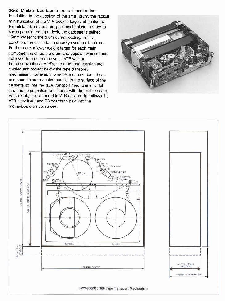
3-2-2. Miniaturized tape transport mechanism
In addition to the adoption of the small drum, the radical
miniaturization of the VTR deck is largely attributed to
the miniaturized tape transport mechanism. In order to
save space in the tape deck, the cassette is shifted
15mm closer to the drum during loading. In this
condition, the cassette shell partly overlaps the drum.
Furthermore, a lower weight target for each main
component such as the drum and capstan was set and
achieved to reduce the overall VTR weight.
In the conventional VTR's, the drum and capstan are
slanted and project below the tape transport
mechanism. However, in one-piece camcorders, these
components are mounted parallel to the surface of the
cassette so that the tape transport mechanism is flat
and has no projection to interfere with the motherboard.
As a result, the flat and thin VTR deck design allows the
VTR deck itself and PC boards to plug into the
motherboard on both sides.

3.3. VTR Electronic Features capacitors. Double Sided Surface Mounting of the
components and 4 layer PC board construction are used
on the main PC boards.3-3-1. Plug-in PC board construction
Each head amplifier, which handles very small signals, is
located close to its video heads and audio heads, and
these signals are amplified to be fed to the signal
processing circuitry. Therefore, the head amplifier is
immune to interference from other electronic circuits.
The motor drive circuit and the full-erase oscillator,
which handle relatively high power signals, are also
located so close to their associated components.
The interference between electronic circuits is greatly
reduced in this way. This enables PC boards of both the
camera and VTR sections to be plugged into the same
motherboard. Thus, most of the harness connections are
eliminated and reliability is thereby remarkably enhanced.
3-3-2. Software servo control IC
The drum servo, capstan servo, and the mechanical
deck are all controlled by newly developed IC's under
software control. The use of these powerful IC's
drastically reduced the number of electronic
components in the servo control and system control
circuitry. This also contributed to the weight reduction
and lowered power consumption.
3-3-5. LCD multiple displays
The displays used for the one-piece camcorder have
also been carefully designed. The BVW-200/300/400
employ a specially selected LCD which works even at
low temperatures.
The following indications are provided in the LCD
multiple display area.
.Time code-8 digits
.Time code status
.Audio 2 CH-16 segments x 2 CH
.Battery status- 7 segments
.VTR warning indication
Two-channel Audio level and Battery status are displayed
on a Bargraph meter that can be read at a glance.
3-3-3. Serial interface among CPU's
The BVW-2001300/400 utilize a total of four CPU's .for
camera control, VTR system control, servo control, and
operational control. These CPU's use a common serial
data bus interface. This intelligent interface among the
CPU's greatly reduces the need for wiring harnesses.
Also, the common data bus that links the camera CPU to
the three CPU's employed in the VTR permit a
sophisticated diagnostic system to be realized in the
camcorder.
3.4. Camera Technical Features
3-4-1. Camera head construction
The camera section consists of a compact optical block
with 3 CCD imagers, six plug-in PC boards which share
the same motherboard with those of the VTR section,
and a viewfinder.
Large Scale Hybrid Integrated Circuits such as DCC
(Dynamic Contrast Control) HIC and Shading HIC, and
high density mounting technology are employed to
reduce the overall PC board surface space to 70% of
the space in conventional cameras.
All the advantages of CCD imager cameras; rugged
operation, high stability, weight and size reduction are
also provided in the BVW-200/300/400 One-piece
Camcorders.
3-3-4. High density circuit board
Use of the latest manufacturing process permits the
one-piece camcorders to extensively use newly
developed HIC (Hybrid Integrated Circuits) and IC. This
not only contributes to the one-piece camcorder's
compact and lightweight design, but also plays a
important role in the reduction of power consumption.
The BVW-200/300/400 use only one Video Modulator IC
for each channel, while previous models required three.
In order to realize the small 4-head drum, newly
developed Rec/playback HIC and Playback Amplifier
ControllC are built into the drum. The IC's and HIC's for
CTDM (Compressed Time Division Multiplex) are also
newly developed.The direct bonding of IC chips, used in the HIC, is also
effective to reduce the overall weight, size, and power
consumption.In order to obtain even higher packing density of the
electronic circuitry, the PC boards use chip resistors and
7
The variable shutter speed is easily selected by a front
panel switch.
.High resolution
The remarkably high horizontal luminance resolution of
700 TV lines is achieved by the use of high density CCD
chips and Sony's Spatial Offset technology.
.High sensitivityIn the HAD sensor CCD, the use of a vertical Overflow
Drain increases the sensor aperture ratio (the
photosensitive part of the CCD area). Thus, this structure
combines high sensitivity with high resolution.
3-4-2. Advanced Sony's CCD technology
The BVW-200/300/400 feature a multitude of advantages
from the use of Sony's CCD technology. The followings
are their general advantages.
.No problem of image burn-in or lag
.Impervious to vibration and shock
.Inherent immunity to strong electric or magnetic fields
.Freedom from registration adjustment
The new of one-piece camcorder BVW-400 adopts the
high resolution 768(H) x 494(V) pixel FIT (Frame Interline
Transfer) HAD (Hole Accumulated Diode) sensor CCD's
for the most complex and quality conscious type of field
production. The BVW-300 is designed to be used for
ENG and EFP applications. The CCD device used in the
BVW-300 is the 768(H) x 493(V) pixel IT (Interline Transfer)
CCD combined with the same HAD sensor technology
as the BVW-400 CCD. Sony's unique CCD technology
employed in the BVW-300/400 is described in detail below.
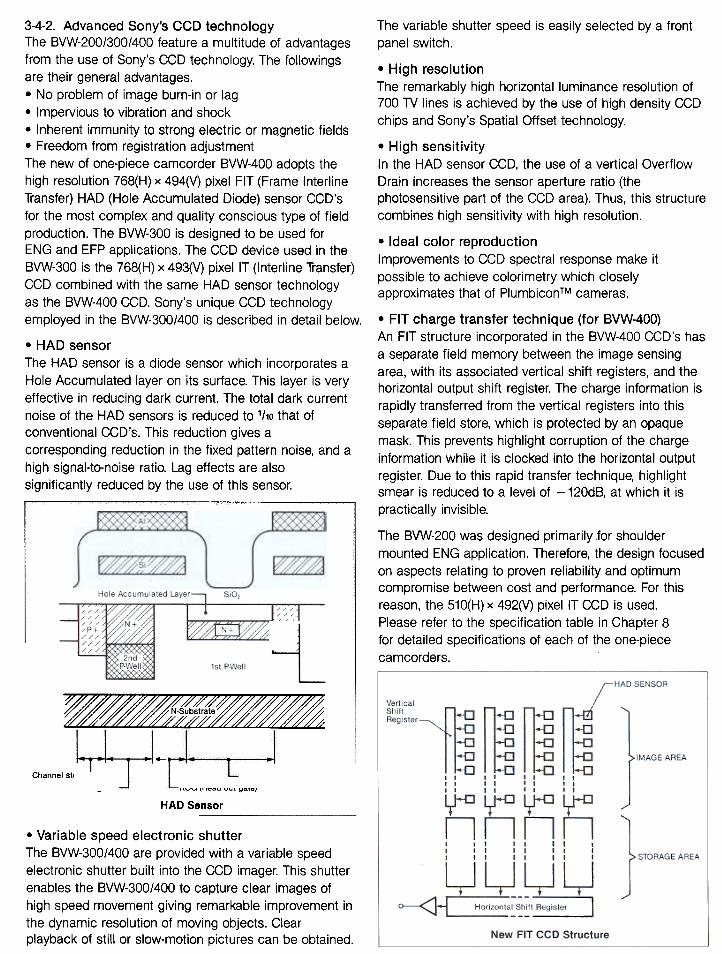
.HAD sensor
The HAD sensor is a diode sensor which incorporates a
Hole Accumulated layer on its surface. This layer is very
effective in reducing dark current. The total dark current
noise of the HAD sensors is reduced to 1ho that of
conventional CCD's. This reduction gives a
corresponding reduction in the fixed pattern noise, and a
high signal-to-noise ratio. Lag effects are also
significantly reduced by the use of this sensor.
.Ideal color reproduction
Improvements to CCD spectral response make it
possible to achieve colorimetry which closely
approximates that of PlumbiconTM cameras.
.FIT charge transfer technique (for BVW-400)
An FIT structure incorporated in the BVW-400 CCD's has
a separate field memory between the image sensing
area, with its associated vertical shift registers, and the
horizontal output shift register. The charge information is
rapidly transferred from the vertical registers into this
separate field store, which is protected by an opaque
mask. This prevents highlight corruption of the charge
information while it is clocked into the horizontal output
register. Due to this rapid transfer technique, highlight
smear is reduced to a level of -120dB, at which it is
practically invisible.
The BVW-200 was designed primarily for shoulder
mounted ENG application. Therefore, the design focused
on aspects relating to proven reliability and optimum
compromise between cost and performance. For this
reason, the 510(H) x 492(V) pixel IT CCD is used.
Please refer to the specification table in Chapter 8
for detailed specifications of each of the one-piece
camcorders.
rH#:~i~~ ~
Hole Accumulated Layer SiO,
/ , ,~ ~"/' 1/// N + /p+
/////////
1st P.Well
~
-.-;
Channel stop-l
V-Register
Sensor
ROG (Read out gate)
HAD Sensor
.Variable speed electronic shutter
The BVW-300/400 are provided with a variable speed
electronic shutter built into the CCD imager. This shutter
enables the BVW-300/400 to capture clear images of
high speed movement giving remarkable improvement in
the dynamic resolution of moving objects. Clear
playback of still or slow-motion pictures can be obtained.
8

4
heat function to be eliminated from the unit. In this way,
the ability to capture important, unrepeatable action is
greatly enhanced.
4-3-2. Viewfinder mechanism
The unique viewfinder mount enables movement in the
forward/backward direction as well as lateral adjustment
Moreover, the viewfinder can also be tilted plus and
minus 90 degrees. The BVW-400 features a viewfinder
rotation mechanism, when equipped with the optional
BKW-401 Viewfinder Rotation Bracket, so that the
viewfinder will not strike the operator's leg while
carried*. In addition, the eye-piece of the BVW-400's
viewfinder can be easily removed for ease of cleaning
and to provide direct observation of the CRT from a
distance.
*This function will also come available for the BVW-200/300. For further
information, please contact the Sony office nearest you.
4.1. Refined Ergonomics
The careful consideration of the Sony design team has
had a marked effect on the ergonomic design of the
BVW-200/300/400. This is reflected in the basic shape
and construction, as well as the layout of the operational
controls in the units. Considering the need for enhanced
mobility and comfortable operation, the length has been
held to a mere 370mm (from lens mount to rear of
battery), and the overall maximum height is 268mm, with
a low center of gravity. The low profile front-end ensures
good visibility in all direction for the operator when used
on the shoulder, and its short length enables well-
balanced operation. In order to accommodate the use of
different lenses and battery systems, the shoulder pad
position is adjustable for perfect balance.
A large carrying handle has been provided in order to
provide security during transport and to allow easy
handling in low angle shooting.
The body is made of rugged diecast magnesium to
prevent interference, and to realize light weight and
durability. The operational controls have been carefully
positioned on the body of the BVW-200/300/400, with
particular care to the location of those primary controls
accessed while shooting from the shoulder. Even the
audio level controls can be easily adjusted by
comfortably reaching behind the unit.
4.2. Rain and Dust.proof Structure
Each joint of the camcorder is sealed with rubber
gasketing to resist water and dust. This strong rain/dust
proof structure is ideal for field use including ENG and
location work in harsh environments.
4.3. Quick Stan Viewfinder BVW-400 Viewfinder Rotation mechanism with the BKW-401
4-3-3. Operational facilities
The ergonomic improvements of the BVW-200/300/400
camcorders also extend to the alpha-numeric readouts
within the viewfinder. The readout can be selected to
report on a wide range of operational conditions
including: rec status, battery alarm, Audio level (ch-1),
Videl level, the preselected color-balance memory, tape
time remaining, filter position, gain settings, shutter
speed (for BVW-300/400 only), and VTR save mode (for
BVW-400 only). The BVW-400's viewfinder also provides
a center marker and a 80% or 90% safety zone
indications. BVW.400 Viewfinder Indications
4-3-1. Optical/CRT
Special attention was paid to the design of the
viewfinder. The innovative 1.511 monochrome viewfinder
supplied with the one-piece camcorders is designed to
increase operational ease. The CAT produces 550 TV
lines of center resolution which, together with a variable
phase corrected peaking control (Dual edge peaking
correction), considerably improves the camera person's
focusing role. A larger 2 inch optical lens is fitted to the
front of the viewfinder. This allows operators to see the
full raster including the corners, even when positioned
behind the camera. A wide range of diopter adjustment
( -3.8- + 0.3) is provided to compensate for differences
in eye sight.
Furthermore, this viewfinder presents a stable picture
within only one second from a cold start. Coupled with
the instant response CCD chip, this means that the
BVW-200/300/400 are capable of capturing images
within one second from 'power-on'. This allows the pre-
9
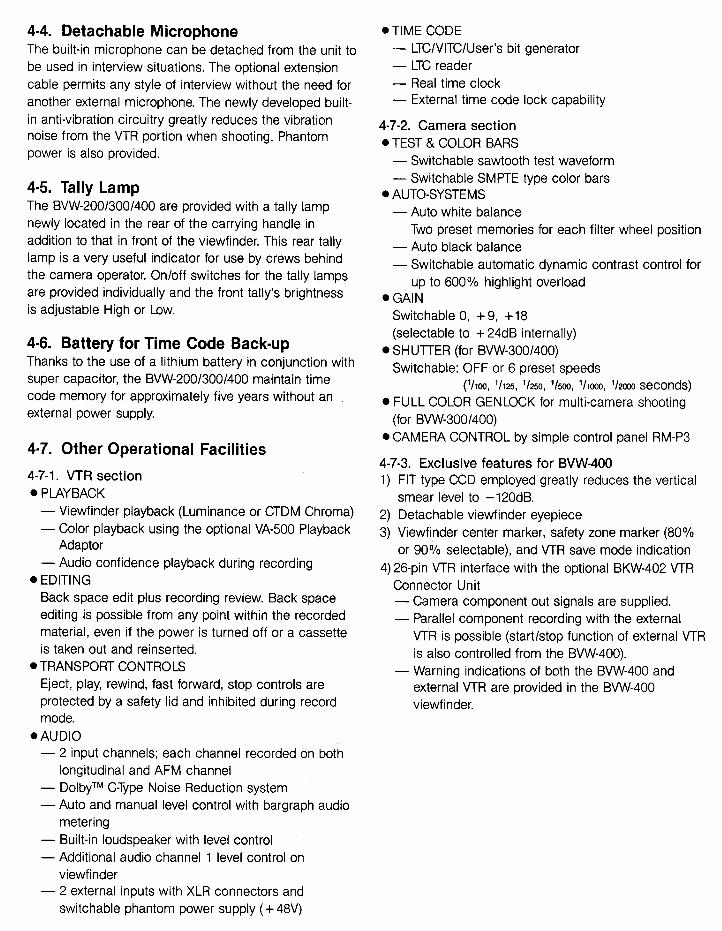
4.4. Detachable M icrophone
The built-in microphone can be detached from the unit to
be used in interview situations. The optional extension
cable permits any style of interview without the need for
another external microphone. The newly developed built-
in anti-vibration circuitry greatly reduces the vibration
noise from the VTR portion when shooting. Phantom
power is also provided.
.TIME CODE-LTC/VITC/User's bit generator-LTC reader-Real time clock-External time code lock capability
4.5. Tally Lamp
The BVW-200/300/400 are provided with a tally lamp
newly located in the rear of the carrying handle in
addition to that in front of the viewfinder. This rear tally
lamp is a very useful indicator for use by crews behind
the camera operator. On/off switches for the tally lamps
are provided individually and the front tally's brightness
is adjustable High or Low.
4-6. Battery for Time Code Back-up
Thanks to the use of a lithium battery in conjunction with
super capacitor, the BVW-200/300/400 maintain time
code memory for approximately five years without an
external power supply.
4.7-2. Camera section
.TEST & COLOR BARS
-Switchable sawtooth test waveform
-Switchable SMPTE type color bars
.AUTO-SYSTEMS
-Auto white balance
Two preset memories for each filter wheel position
-Auto black balance
-Switchable automatic dynamic contrast control for
up to 600% highlight overload
.GAIN
Switchable 0, + 9, + 18
(selectable to + 24dB internally)
.SHUTTER (for BVW-300/400)
Switchable: OFF or 6 preset speeds
rhoo, 1/125, 1/250, 1/500, 1/1000, 1/2000 seconds)
.FULL COLOR GENLOCK for multi-camera shooting
(for BVW-300/400)
.CAMERA CONTROL by simple control panel RM-P3
4-7-3. Exclusive features for BVW-400
1) FIT type CCD employed greatly reduces the vertical
smear level to -120dB.
2) Detachable viewfinder eyepiece
3) Viewfinder center marker, safety zone marker (80%
or 90% selectable), and VTR save mode indication
4) 26-pin VTR interface with the optional BKW-402 VTR
Connector Unit
-Camera component out signals are supplied.
-Parallel component recording with the external
VTR is possible (start/stop function of external VTR
is also controlled from the BVW-400).
-Warning indications of both the BVW-400 and
external VTR are provided in the BVW-400
viewfinder.
4.7. Other Operational Facilities
4-7-1. VTR section
.PLAYBACK
-Viewfinder playback (Luminance or CTDM Chroma)
-Color playback using the optional VA-500 Playback
Adaptor
-Audio confidence playback during recording
.EDITING
Back space edit plus recording review. Back space
editing is possible from any point within the recorded
material, even if the power is turned off or a cassette
is taken out and reinserted.
.TRANSPORT CONTROLS
Eject, play, rewind, fast forward, stop controls are
protected by a safety lid and inhibited during record
mode.
.AUDIO
-2 input channels; each channel recorded on both
longitudinal and AFM channel
-DolbyTM C-Type Noise Reduction system
-Auto and manual level control with bargraph audio
metering-Built-in loudspeaker with level control
-Additional audio channel 1 level control on
viewfinder
-2 external inputs with XLR connectors and
switchable phantom power supply ( + 48V)
10
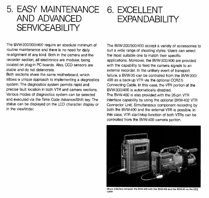
The BVW-200/300/400 require an absolute minimum of
routine maintenance and there is no need for daily
re-alignment of any kind. Both in the camera and the
recorder section, all electronics are modular, being
located on plug-in PC boards. Also, CCD sensors are
stable and do not deteriorate.
Both sections share the same motherboard, which
allows a unique approach to implementing a diagnostics
system. The diagnostics system permits rapid and
precise fault location in both VTR and camera sections.
Various modes of diagnostics system can be selected
and executed via the Time Code Advance/Shift key. The
status can be displayed on the LCD character display or
in the viewfinder.
The BVW-200/300/400 accept a variety of accessories to
suit a wide range of shooting styles. Users can select
the most suitable one to match their specific
applications. Moreover, the BVW-300/400 are provided
with the capability to feed the camera signals to an
external recorder. In the unlikely event of transport
failure, a BVW-35 can be controlled from the BVW-300/
400 as a back-up VTR via the optional CCRZ -5
Connecting Cable. In this case, the VTR portion of the
BVW-300/400 is automatically disabled.
The BVW-400 is also provided with the 26-pin VTR
interface capability by using the optional BKW-402 VTR
Connector Unit. Simultaneous component recording by
both the BVW-400 and the external VTR is possible. In
this case, VTR start/stop function of both VTRs can be
controlled from the BVW-400 camera portion.
26-pin interface between the BVW-400 with the BKW-402 and the BVW-35 via the CCZcable
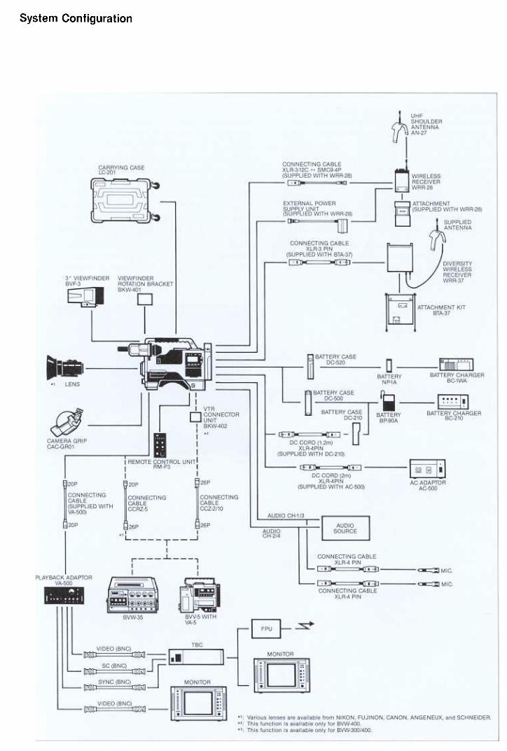
System Configuration
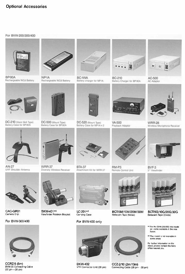
Optional Accessories
CAC-GRO1
Camera Grip
LC-201 *2
Carrying Case
BC~5M/10M/20M/30M
Betacam Tape (Metal)
BCT-5G/10G/20G/30G
Betacam Tape (Oxide)
BKW-401 *1
Viewfinder Rotation Bracket
For BVW-300/400 For BVW-400 only
., For the BVW-200/300 this model
will come available in the nearfuture
., This model Is not available in
some areas
For further information on theabove, piease contact the Sonyoffice nearest you
BKW-402
VTR Connector Unit (26 pin)
CCRZ-5 (5m)
BVW-35 Connecting Cable
(20 pin-26 pin)
CCZ-2/10 (2m/10m)
Connecting Cable (26 pin-26 pin)
13
0 $ .
,
O AUDIO LEVEL CH-1 controlf) PEAKING control (on/off and volume control)
e Tally lampe CONTRAST control
0 BRIGHT control
0 AUDIO (audio channel-1 recording level) and TAPE (tape remaining time)
INDICATOR switch
.ZEBRA, MARKER switch (ZEBRA switch for BVW-200/300)
O TALLY switch (high, low, or off selectable)
0 VTR START button
G SHUTTER selector (for BVW-300/400).AUTO W/B BAL (automatic white/black balance adjustment) switch
.FILTER selector
.ALARM control
.MONITOR control
G Speakere EJECT button
.REW (rewind) button and lamp
e FFWD (fast forward) button and lamp
.PLAY (playback) button and lamp
G STOP button
.WARNING lamp
.HOLD (display hold) button
.RESET (counter reset) button
.DISPLAY switch (User bit, Time code, or CTL selectable)
e LIGHT switch
.LCD display window
.AUDIO LEVEL CH-1 and CH-2 (audio channel 1 and channel 2 recording
ievel) controls.MONITOR SELECT switch (Audio CH-1, MIX or CH-2 selectable)
.MONITOR switch
(PB (playback sound during recording) or E-E sound selectable)
G AUDIO SELECT CH-1 and CH-2 switches
(Auto or manual level adjustment selectable, respectively)
G ADVANCE button (To set Time Code or User bit)
.SHIFT button (To set Time Code or User bit)
.DIAGNOSTIC switch
.DF/NDF (drop frame/non drop frame) switch
e AUDIO IN (Input) switches
(Select audio input signals from the FRON~MIC (microphone connected to
MIC IN connector), REAR MIC (microphone connected to AUDIO IN CH-1 or
CH-2 connector), REAR-LINE (audio source connected to AUDIO IN CH-1 or
CH-2 connector))
.VITC (VITC line setting) controls
.F-RUN/R-RUN (free run/recording run) switch
.REAL TIME (time of the day) switch
.DOLBY NR switch
e VTR (VTR power mode) switch (STAND BY mode or SAVE mode selectable)
G GAIN selector (0/9/18dB)
.OUTPUT/DCC (output signal/Dynamic Contrast Control) selector
.WHITE BAL (balance memory) selector
.CTDM (Compressed Time Division Multiplex) piayback button
.POWER switch
e EARPHONE jack (mini jack).Battery case for NP-1A
e DC IN (external power input) connector (XLR 4-pin, Male) (Connects the DC
power cord of the optional AC-500 AC adaptor when operating on AC power)
.DC OUT connector (Supplies DC power to the optional wireless microphone)
~ VIDEO OUT connector (BNC)
.Phantom switches
~ AUDIO IN CH-1 and AUDIO IN CH-2 connectors (XLR 3-pin, Female)
iI Back tally lamp switch (ON/OFF)
.Back tally lampti Hooks for shoulder strap
.Light shoe (To attach a video light)
.Lens mount (special bayonet type)
.REMOTE connector (6-pln)
(Connects the optional RM-P3 Remote Control Unit)
.Shoulder pad~ GENLOCK VIDEO IN connector (BNC)
(TC LOCK VIDEO IN connector for BVW-200)
.VIDEO OUT connector (BNC)
(I TC IN (Time code input for time code lock) connector (BNC)
.TC OUT (time code output for time code lock) connector (BNC)
~ PB ADAPTOR (playback adaptor) connector (20-pin)
(9 MIC IN connector (XLR 3-pin, female)
41 PEDESTAL control
\I LENS connector (12-pin)
(i Tripod mount
14
.. . . .


BVW.200 BVW-300
Weight".
Approx,49kg(1b~13oz}
~
Approx6,9kg (151b30Z) Appr9*,7;0~(1f)1b7~J
0012V:~2 ,vc~~0;cQ)"
!9W
Operating weight!inc!uQjng NP.1Abattery, cassette,
and!$!e~113x9Ien~W\\Dex1:nger}Po -, c;;-werrequlrements
':CC," ,i~C
~; .~ ,c, ,
~rat[ng temperature;
.C':'HumIdity c
,"" ,"";;i.cC011linu o u s~Qp eratl n9~t i me{~j th ~ B1 A}
Tapespeed j
Playbacklrecordingti~c
"Q'QA; 60:OA (4 °'F "- t40°F'1".4'v!9+,~,CCc'ct9c+" c'k
~~~t ~~~~~~~(r~' ~1i~e~u ~ ~!~~ l,.c
Approx,pOm!n:r'
Approx,§5mjn,
Ap "'~ 5 "~Qx,~0~!n
c!1,$Qcm!sec.
tess1han9min.withBO1'$J:)M"C"
~
~than~min;WithBCT+3oM:'i;::"}l'"~c:,
I Rewind tinne,-rSiQnal inputs
tEARPHONE OUT-,
PLAYBACK ADAPTOR-
Min!Jack",,"
"'~~~
I DCfN *LR4;Pjh(fOr the opl!onaJAC:5QO)
~~ 4.pil1(!Qrwire!esS micr9phone),DC11-17V,O 1A max.
I CAMERA
~
c
13~hjp?13., c cP "
I'
ckup devIcePictu;e e,e;;;enis":;
OptIcal systemcc
Built-in filters cShutter speed
cLe~s mount
Video output
I Con~ecto~s
51NH) x 4921\n,'", " ~\,{ 768(H)x 49~V)
~
Not applicable , 1!00 \ ! 125 'J2s0 j 1.00 ) hOdO q~seconds
'--\A" -C-~n${12'Plf),R~~~e,6.
.2000 JI))(withF $,6, e9,9"'lor~flOOlive""c
Appr~,!;IU)(F14\;n$,+je
59dB;
550TVJ\nes
,62dS
~,~5%\afizone$, without lens)
.2 I Sensitivity
~ Minimum illumination"'~ Video signal-to.noise ratio01 ,~ H~!zon\a!!esojutiono Registration
Controls
BeloW measurable level (witho~t I:ns),
2sec;
monochrome
BRIGHT
ONIOFFSw!tch (for BVW-200!300),ON/OFF "t hSWICn
~~pmal resolution 550lV 1ines
sh arp.d ir e ctldi1 a! ( detach able }
Tripod adaptor (Vcr14) (1), Extension board (1), Rain cOVer{1)cSho belt(1),Operatfngandmainjenancem~nuaf(1)
}lnte(line Tran$fe(CCtCc
i}x494(V)c ,
"BETACAM" and "BETACAM SP" are trademarks of Sony Corporation.
Dolby Is a tradewark of the Dolby Laboratories Licensing Corporation
Design and specifications subject to change without notice
'7

.
.
Sony Corporation
Printed in Japan @ SONYBC-oO212M K1845H P90O3P1-OO5. 75