
BestFlex Power - cisco-eagle.com
30
BestFlex Power BFP 1.5 and BFP 1.9 Conveyor System with Accumulation Operator’s Manual FMH Conveyors LLC p. 800.327.9209 Part Number 99042 107 Flint Street t. 844.FMH.SERVICE Effective October 2015 Jonesboro, AR 72401 f. 870.935.3661 www.fmhconveyors.com
Transcript of BestFlex Power - cisco-eagle.com

BestFlex PowerBFP 1.5 and BFP 1.9Conveyor Systemwith Read-Between-Roller AccumulationOperator’s Manual
FMH Conveyors p. 800.327.9209 Part Number 99058-99042-UL107 Flint Street t. 844.FMH.SERVICE Effective September 2015Jonesboro, AR 72401 f. 870.935.3661 www.fmhconveyors.com
BestFlex PowerBFP 1.5 and BFP 1.9Conveyor Systemwith Accumulation
Operator’s Manual
FMH Conveyors LLC p. 800.327.9209 Part Number 99042107 Flint Street t. 844.FMH.SERVICE Effective October 2015Jonesboro, AR 72401 f. 870.935.3661 www.fmhconveyors.com

2
Dear Operator,
We at FMH Conveyors would like to thank you for selecting our BestFlex® power conveyorsystem as the solution to your conveying needs.
Your BestFlex® system is supported by a group of factory trained customer servicerepresentatives. They can be reached via our toll free number 1-800-327-9209. Whetheryour needs require assistance from the factory or in the field, please do not hesitate to call.Our team is eager to help.
Thank you once again for purchasing our BestFlex conveyor system. We look forward tofulfilling your future requirements.
Sincerely,FMH Conveyors
FMH Conveyors Operator’s ManualBestFlex BFP 1.5 and BFP 1.9

3
Thank You 2
Warranty Statement, Service Instructions and Safety Information 4
General Operation 5
Accumulation Full Interface Signal 5
Installation Instructions and Maintenance Schedule 6
DC Motor Brush Maintenance 7
Accumulation Troubleshooting Guide 8-10
Circuit Component Layout 11
Leg Mounted Photo-SensorsInput Zone Layout and Parts List 12-13
Middle Zone Layout and Parts List 14-15
Last Zone Layout and Parts List 16-17
Read-Between-Roller Mounted Photo-SensorsInput Zone Layout and Parts List 18-19
Middle Zone Layout and Parts List 20-21
Last Zone Layout and Parts List 22-23
Power Supply Connection Diagram 25
Zone Connection Diagram 26
Interface Connection Diagram 27
Receiving Interface Connection Diagram 28
Recommended Spare Parts List 29
Addendum A: Order Specific Manuals, Inserts and Drawings (as required)
Table of Contents
FMH Conveyors Operator’s ManualBestFlex BFP 1.5 and BFP 1.9

4
FMH Conveyors Operator’s ManualBestFlex BFP 1.5 and BFP 1.9
Service InstructionsIf your FMH Conveyor needs service or replacement parts, please contact your distributor orour factory toll free at 800-327-9209.
Your FMH Conveyor is protected by our premier warranty. F M H Conveyors will replace, free ofcharge, parts that are damaged during the course of normal operation due to material or workmanshipdefects. This warranty extends for a period of two (2) years on all mechanical components and one (1)year on all electrical components (measured from the date you tookpossession of your conveyor.)
This warranty does not cover damage due to accident, misuse, abuse and negligence. Thiswarranty does not cover damage due to improper operation or maintenance, connection toimproper voltage supply, or attempted repair/modification by anyone other than an authorizedFMH Conveyors service personnel.
For specific warranty information or assistance, please contact your FMH Conveyors salesrepresentative at 800-327-9209.
l Move conveyor only by grasping the handles located on each side at both ends of theconveyor.
l When expanding or compacting your conveyor, keep hands, clothing and other items clearof the sidebars.
l Do not exceed the conveyor load capacity, as it may result in possible operator injury orconveyor damage.
l Avoid wearing excessively loose clothing when working with moving equipment.l Keep long hair pulled up to prevent it from becoming caught in moving parts.l Broken or worn parts must be immediately replaced.l FMH Conveyors must only be serviced by properly trained and qualified technicians.l Conveyor’s power cord must be connected to a grounded receptacle that is protected by
an over current device rated at no more than 15 amps, unless otherwise specified.l Never service a conveyor with the power applied. Always disconnect power before servicing
equipment.l Never operate conveyor with an electrical enclosure open.
Safety Information
Warranty Statement

5
General Operation
The BestFlex Power Conveyor is a flexible, expandable powered conveyor that operates from astandard 115VAC grounded outlet. (Unless otherwise noted.)
The accumulation option allows zero pressure accumulation of packages in individual zonesalong the conveyor. Packages are detected by photoelectric sensors located at the end ofeach zone. When no packages are on the conveyor, all zones will run. The first packageplaced on the conveyor will travel to the last zone on the discharge end of the conveyor andstop when it breaks that zone’s photoeye beam. The remaining zones continue to run. Thenext package placed on the conveyor will stop at the next-to-last zone. Packages will continueto accumulate the length of the conveyor. This allows full utilization of the conveyor withoutletting packages become damaged from over crowding or “bunching up” on the conveyor.
When the package in the discharge end zone is removed from the conveyor, all zones will startand the packages will again “accumulate” toward the discharge end of the conveyor.
The accumulation conveyor comes with photoelectric sensors set in two configurations. Notethat the configuration is determined by the customer at the time of the order.
One configuration is with the photo-eyes mounted on the leg above and outside the conveyorbed. This configuration is known as Leg Mount Optics.
The second configuration is with the photo-eyes mounted slightly below and in the conveyorbed, at the leg locations. This configuration is known as Read Between Roller Optics.
Accumulation Full Interface SignalTwo sets of dry contacts, one normally open and one normally closed, are provided to give aninterface signal from the BestFlex conveyor to a host control system. The normally open contactswill be closed anytime one or more zones of the BestFlex Accumulation conveyor are running. Aterminal block for these contacts is provided on the power supply board located in the largerenclosure at the end of the conveyor. (Refer to the Power Supply Connection Diagram.) Thisterminal block is labeled “Extra Contact”. The individual terminals are labeled “NO” (normallyopen), “COM” (common), “NC” (normally closed) and “GRD” (ground). These contacts are ratedup to 10A/250VAC or 10A/30VDC.
CAUTION: Always unplug the 115VAC power cord before working on the unit or opening anyelectrical enclosures. Never operate the conveyor with the enclosures open.
FMH Conveyors Operator’s ManualBestFlex BFP 1.5 and BFP 1.9

6
Installation Instructions
1) Unpack the BestFlex Power Conveyor and inspect for possible damage that may haveoccurred during shipping. Pay particular attention to the wiring to ensure that no wires arepulled loose or damaged in any way. If you find any damage, contact the factory beforeapplying power to the conveyor.
2) Make sure all Start/Stop push-buttons are in the STOP position (there will be one at each endof the conveyor.)
3) Roll the unit into position. If applicable, use the connect hooks to attach the Best/Flex to a rigidconveyor.
4) Plug the power cord into a 115VAC grounded receptacle.5) Release all Start/Stop push-buttons (a single Start/Stop push-button that has the Stop button
depressed will prevent the conveyor from running.) There may be a stand-alone motormotor controller mounted near the middle of the unit. If this is the case, make sure its switchis in the “On” position. All switches must be in the “Start”, “Run”, or “On” postion.
6) Adjust the speed of the conveyor to suit the application. Adjust the speed by turning thepotentiometer. Depending on the unit configuration, the potentioment will either be located onthe main power enclosure or the motor controller mounted near the middle of the conveyor.
7) Begin placing packages on the conveyor. They will travel to the last available zone andstop until packages are removed from the discharge end.
The BestFlex Power Conveyor is virtually maintenance free. We do recommend that youregularly inspect the unit to ensure proper operation of mechanical and safety systems.
DAILY:
l Keep the conveyor clean and free of debris, dirt and grease accumulation.
l Periodically lubricate all slotted components with a lightweight lubricant to ensure smoothand easy operation.
l Inspect wires and cables for damage. If damage to wires or cables is found, disconnectthe power cord immediately and do not operate unit until proper repair is completed.
l Inspect belts for wear. Replace excessively worn belts.
l Inspect sidebar nuts and bolts for looseness or missing parts. Tighten or replace asneeded.
l Make sure reflectors and photoeyes are clean, unobstructed and properly aligned.
l Verify all Start/Stop push-buttons operate properly.
Maintenance Schedule
FMH Conveyors Operator’s ManualBestFlex BFP 1.5 and BFP 1.9

7Figure 1
Photo 1: Typical Brush Location
Unscrew cap toremove brush
Photo 2
Line tabs upas shown
All motors used to power the conveying surfaces of the BestFlex Powered Conveyors are DCpermanent magnet motors. These motors have a pair of serviceable brushes that wear with use.Brush life is affected by the speed of the motor, the loads being conveyed, the number of start-stopcycles and other factors. Therefore, brush life will vary from application to application.
To ensure long motor life, brush inspection should be included in the normal maintenance schedule.Brushes should be periodically removed, visually inspected and measured.
The brushes are accessed by removing the two caps on the end of the motor opposite of thegearbox (see photos below). Use a proper fitting flat head screwdriver to avoid damaging the cap.With the cap removed, the brush may be removed from its holder by pulling on the spring. Visuallyinspect the brushes for chips or grooves. The shunt wire should not be frayed or broken. The brushshould be replaced if it measures 0.125 inches or less as shown in Figure 1. Possible armaturedamage could result from running the brushes beyond this wear point.
When being installed, the brush should slide freely into the holder. The brass contact connected tothe top of the spring should be installed so its tabs are aligned with the motor shaft (see Photo 2).One tab should be facing the rear of the motor and the other tab toward the front. The tabs shouldgo easily into the brush holder. Do not over tighten the plastic cap that holds the brush in place.
DC Motor Brush Maintenance
FMH Conveyors Operator’s ManualBestFlex BFP 1.5 and BFP 1.9

8
Accumulation Troubleshooting GuideTo use this guide, find the heading that best fits your conveyor’s condition and check thenumbered items in the order they appear. It is important to proceed in the order given since itis assumed at each item that all preceding items under that heading have passed inspection.
CAUTION: Electrical systems should only be serviced by qualified personnel. Refer toand observe all local codes and OSHA guidelines for LOCKOUT/TAGOUT procedures.Make sure all power has been disconnected before opening any enclosure. Keep handsand tools away from electrical circuits when power is applied. 115VAC is present evenwhen the conveyor is stopped by the STOP switch. The only way to guard against electrical shock is tounplug the conveyor from its AC power source before servicing.
Diagnostic LEDsTo aid in troubleshooting, there are a number of LEDs mounted on the power supply printedcircuit board (PCB) in the larger enclosure on the first leg of the system and on each accumu-lation PCB in the smaller enclosures located at each motor. These LEDs are shown on thesystem wire connection diagrams and their meanings are listed here.
Power Supply Board LEDs and Neon Lamp:RED On when STOP button is pushed and RELAY1 is off.GREEN On when 17VDC is present through the DC fuse.LARGE AMBER On when the photoeye connected to the power supply is blocked.SMALL AMBER On when RELAY2 is energized.NEON LAMP On when RELAY1 is energized and AC power is supplied to the DC
controller.
Accumulation Board LEDs:RED On when that zone is stopped and stopped signal is sent to adjacent zones.AMBER On when the photoeye used for forward accumulation is blocked.GREEN On when the photoeye used for reverse accumulation is blocked.
NO MOTOR RUNS:
1) Check AC power coming into conveyor.a) Make sure the unit is plugged into a hot 115VAC outlet.b) Check the circuit breaker mounted in the side of the power supply enclosure. If
button is out an overload has occurred. The fault causing this condition must becleared before continuing. Once the fault is corrected, reset the breaker by pushing it in.
c) For Leg Mounted Optics, if AC power is present, at least one LED on top of eachphoto eye will be on since the DC voltage supplying the photoeyes is derived from theAC power.
d) AC power can be verified with an appropriate voltage meter across the L1 and E-Stopterminals on the power supply board.
FMH Conveyors Operator’s ManualBestFlex BFP 1.5 and BFP 1.9

9
Accumulation Troubleshooting Guide (cont.)
2) Check DC control voltage.a) Check that the Green LED on the power supply is on. If LED is off and AC voltage is
present, check the ¾ amp and 2 amp fuses on the power supply board. If a fuse isblown, repair any electrical shorts or overload conditions before continuing. If fuses arenot blown and the Green LED is not on, the power supply board has failed.
b) If the Green LED is on, check for DC voltage at accumulation zones by blocking a photo-eye for that zone. (For RBR photoeyes, an LED should light indicating the PE is blocked.For Leg-mounted optics, blocking the photoeye should cause the combination of illumin-ated LEDs should change indicating the optic is blocked.) The Amber LED on the accum-ulation board should be lit when that zone’s photoeye is blocked. If this LED is not on,make sure all communication cables are plugged in. Check the communication cablebetween power supply board and first zone accumulation board.
3) Check for AC power coming into the DC motor controller.a) The neon lamp on the power supply board should be on whenever AC power is
supplied to the DC controller. If this lamp is off and the Red LED on the power supplyboard is also off, check the 15 amp fuse on the power supply board that powers the DCcontroller. If this fuse is good, the relay on the power supply board has failed.
b) If the Red LED is on, check to be sure all STOP pushbuttons have been released.c) Check the AC fuse on the DC motor controller.d) AC power can be verified with a volt meter at the DC controller.
4) Check for DC power on the output side of the DC motor controller.a) If the unit has a DC Motor Contoller mounted near the center of the unit, make sure the
forward/reverse switch is not in the middle position and make sure the speed control isnot turned down to “zero.”
b) Check the DC fuse on the DC controller. (This is the ceramic fuse.) Either remove the fusefor continuity or check for voltage between the output side of the fuse and ground. Thisvalue should be approximately 90VDC.
c) If the fuse is blown, the cause could be either a shorted motor cord or a motor drawingexcessive current.
d) If the DC fuse is good, the plug-in resistor is in place, and no DC voltage is present at theoutput of the DC motor controller, the controller has failed.
FMH Conveyors Operator’s ManualBestFlex BFP 1.5 and BFP 1.9

10
ONE OR MORE ZONES WILL NOT RUN:
1) If it’s an end zone, check the zone’s photoeye for alignment and proper functioning.a) For Leg-mounted Optics, the photoeye’s Green LED will be on if its beam is blocked or
the eye is not aligned with reflector. If the Green LED does not come on when the beam isbroken, the photoeye is defective. For RBR Optics, an LED on the optic should be litwhen the optic is blocked; if this is not the case, the RBR optic may be defective.
2) Check accumulation board for control voltage.a) Observe photoeye’s LEDs (leg-mounted optics only). They are powered from the
accumulation’s control voltage. If none are on, the photoeye may not have power. Controlvoltage is supplied to each accumulation board by the communication cable connected tothe PREVIOUS modular connector. Check cable for broken wires or defective connectors.
b) Block that zone’s photoeye. The Amber LED on the accumulation board should comeon when the photoeye’s beam is broken.
3) Check for DC voltage at the motor cable’s connector on the accumulation board.a) If no voltage is present, check the fuse on the accumulation board. If the fuse is blown,
check for shorts in the motor cable and in the motor and then replace the fuse.b) If no voltage is present and the fuse is not blown indicating a short or overload, the
accumulation board is bad.c) If voltage is present at the motor cable’s connector, the motor or its cable is defective.
ONE PHOTOEYE STOPS TWO OR MORE ZONES:
1) Check alignment of photoeyes in zones that stop when the next zone’s photoeye isblocked.a) With Leg-mounted optics, if a zone’s photoeye is not properly aligned with its reflector
and the next zone’s eye is blocked, both zones will operate as one. The Green LED on thetop of the photoeye should only be lit when the photoeye is blocked. It will not be on whenthe photoeye is properly lined up with its reflector. When a photo eye’s beam is not beingreflected back to the photoeye the accumulation board’s Amber LED will be lit. If the opticsare properly aligned and one photoeye stop its zone as well as the previous zone then theaccumulation board in the previous zone is probably defective.
b) With RBR Optics, if a zone’s photoeyes are controlling there own zone plus the previouszone, check the optics in the previous zone to make sure one or more optics are notpicking up a false signal. If no false signals are being detected, the accumulation board ofthe previous zone is probably defective
ZONE WILL NOT SHUT OFF WHEN PHOTOEYE IS BLOCKED AND NEXT ZONE IS OFF:
1) Check photoeye for proper function.a) Make sure the accumulation’s Amber LED is on when the photoeye is blocked. If itdoes not come on, check the connections from the photoeye cable at the board’sconnector. The photoeye could also be defective.
Accumulation Troubleshooting Guide (cont.)
FMH Conveyors Operator’s ManualBestFlex BFP 1.5 and BFP 1.9

11
Circuit Component Layout
FMH Conveyors Operator’s ManualBestFlex BFP 1.5 and BFP 1.9

12
Input Zone Layout: Leg Mount Accumulation
FMH Conveyors Operator’s ManualBestFlex BFP 1.5 and BFP 1.9
13
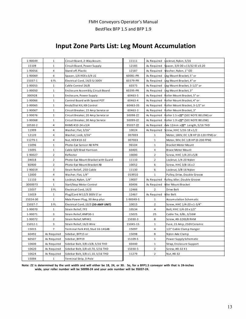
Input Zone Parts List: Leg Mount Accumulation
1-90049 1 Circuit Board, 2-Way Accum . 11111 As Required Locknut, Nylon, 5/16
15109 1 Circuit Board, Power Supply 12185 As Required Spacer, 3/4 OD x 13/32 ID x 0.20
1-90056 4 Stand off, Plastic 12187 As Required Was her, Nylon, 1" OD
1-90069 4 Spacer, 1/4 HEX x 3/4 LG 60081-PR As Required Leg Mount Bracket, 5" or
15037-1 6 Ft. Electrical Cord, 14/3 SJ 300V 60379-PR As Required Leg Mount Bracket, 4" or
1-90055 1 Cable Control 26/8 60375 As Required Leg Mount Bracket, 3-1/2" or
1-90050 1 Enclos ure Ass em bly, Circuit Board 60295-PR As Required Leg Mount Bracket, 3"
300928 1 Enclos ure, Power Supply 60463-5 As Required Roller Mount Bracket, 5" or
1-90066 1 Control Board with Speed POT 60463-4 As Required Roller Mount Bracket, 4" or
1-90065 1 Knob/Dial Kit, KB Control 60463-35 As Required Roller Mount Bracket, 3-1/2" or
1-90067 1 Circuit Breaker, 15 Am p Service or 60463-3 As Required Roller Mount Bracket, 3"
1-90076 1 Circuit Breaker, 20 Am p Service or 50098-ZZ As Required Roller 1.5 x ZZ* (SEE NOTE BELOW) or
1-90068 1 Circuit Breaker, 30 Am p Service 50099-ZZ As Required Roller 1.9 x ZZ* (SEE NOTE BELOW)
10530-2 4 RHMS #10-24 x 3/4 95037-ZZ As Required Axle 12m m x ZZ* Length, 5/16 THD
11999 4 Was her, Flat, 3/16" 10024 As Required Screw, HHC 5/16-18 x 1/2
12120 4 Was her, Lock, 3/16" 007003 1 Motor, 180V, DC 1/8 HP (0-120 FPM) or
11279-1 4 Nut, HEX #10-32 007003 1 Motor, 90V, DC 1/8 HP (0-200 FPM)
15096 1 Photo-Eye Sens or AB NPN 96504 1 Bracket Motor Mount
15095 1 Cable Q/D Brad Harris on 60405 4 Brace Motor Mount
1-90027 2 Reflector 10000 2 Screw, HHC 1/4-20 x 5/8
04018 2 Photo-Eye Mount Bracket with Guard 11110 2 Locknut, 1/4-20 Nylon
60900 2 Photo-Eye Mount Bracket AB 10052 6 Screw, HHC 3/8-16 x 2
1-90019 3 Strain Relief, .250 Cable 11130 6 Locknut, 3/8-16 Nylon
12000 4 Was her, Flat, 1/4" 019910 1 Pulley, Drive, Double Groove
11110 6 Locknut, Nylon, 1/4" 19007 As Required Pulley, Idler, Double Groove
3000073 1 Start/Stop Motor Control 60406 As Required Idler Mount Bracket
15037 3 Ft. Electrical Cord, 16/3 12466 2 Drive Belt
15019 1 Plug/Cord M 12/3 300V 3' or 12467 As Required Idler Belt
15024-30 1 Male Power Plug, 30 Am p plus 1-90049-S 1 Accum ulation Schem atic
15037-7 3 Ft. Electrical Cord, 10/3 (30-AMP UNIT) 10015 2 Screw, HHC 1/4-20 x 1-3/4"
1-90070 1 Strain Relief, 7P2 10534 4 Bolt, HHC 1/4-20 x 1/2"
1-90071 3 Strain Relief, #MP30-1 15025 25 Cable Tie, 3/8L, 3/16W
1-90072 2 Strain Relief, MP4K1 15030-3 8 Screw, #8-32X3/8 RHM
15012-1 3 Strain Relief, 16/3 Wire 15045-15 1 Fus e, 15 Am p, 250V Ceram ic
15015 7 Term inal Fork #10, Stud 16-14GAB 15097 4 1/2" Cable Clam p Hanger
60492 As Required Sidebar, BFP15 or 15098 8 Nylon Axle Clam p
60507 As Required Sidebar, BFP19 15109-S 1 Power Supply Schem atic
10600 As Required Sidebar Bolt, 3/8 x 3/8, 5/16 THD 60440 1 Strap, Enclos ure Support
10620 As Required Sidebar Bolt, 3/8 x 0.70, 5/16 THD 15030-5 2 Screw, #8-32 X 1
10624 As Required Sidebar Bolt, 3/8 x 1.10, 5/16 THD 11279 2 Nut, #8-32
15094 1 Term inal Strip, 3-Pole
Note: ZZ is determined by the unit width and will either be 18, 24, or 30. So, for a BFP1.5 conveyor with that is 24-incheswide, your roller number will be 50098-24 and your axle number will be 95037-24.
FMH Conveyors Operator’s ManualBestFlex BFP 1.5 and BFP 1.9

14
Middle Zone Layout: Leg Mount Accumulation
FMH Conveyors Operator’s ManualBestFlex BFP 1.5 and BFP 1.9

15
Middle Zone Parts List: Leg Mount Accumulation
1-90049 1 Circuit Board, 2-Way Accum. 15094 1 Terminal Strip, 3-Pole
1-90056 4 Stand off, Plastic 60463-5 As Required Roller Mount Bracket, 5" or
15037-1 6 Ft. Electrical Cord, 14/3 SJ 300V 60463-4 As Required Roller Mount Bracket, 4" or
1-90055 1 Cable Control 26/8 60463-35 As Required Roller Mount Bracket, 3-1/2" or
1-90050 1 Enclosure Assembly, Circuit Board 60463-3 As Required Roller Mount Bracket, 3"
1-90081 1 Enclosure Cover 50098-ZZ As Required Roller 1.5 x ZZ* (SEE NOTE BELOW) or
1-90152 1 Thumb Screw, #8-32 50099-ZZ As Required Roller 1.9 x ZZ* (SEE NOTE BELOW)
1-90153 1 Nut, U-Clip, #8-32 95037-ZZ As Required Axle 12mm x ZZ* Length, 5/16 THD
15096 1 Photo-Eye Sensor AB NPN 10024 As Required Screw, HHC 5/16-18 x 1/2
15095 1 Cable Q/D Brad Harrison 007003 1 Motor, 180V, DC 1/8 HP (0-120 FPM) or
1-90027 2 Reflector 007003 1 Motor, 90V, DC 1/8 HP (0-200 FPM)
04018 2 Photo-Eye Mount Bracket with Guard 96504 1 Bracket Motor Mount
60900 2 Photo-Eye Mount Bracket AB 60405 4 Brace Motor Mount
12000 2 Washer, Flat, 1/4" 10000 2 Screw, HHC 1/4-20 x 5/8
11110 2 Locknut, Nylon, 1/4" 11110 2 Locknut, 1/4-20 Nylon
1-90070 1 Strain Relief, 7P2 10052 6 Screw, HHC 3/8-16 x 2
1-90071 3 Strain Relief, #MP30-1 11130 6 Locknut, 3/8-16 Nylon
1-90072 2 Strain Relief, MP4K1 019910 1 Pulley, Drive, Double Groove
15012-1 3 Strain Relief, 16/3 Wire 19007 As Required Pulley, Idler, Double Groove
15015 7 Terminal Fork #10, Stud 16-14GAB 60406 As Required Idler Mount Bracket
60492 As Required Sidebar, BFP15 or 12466 2 Drive Belt
60507 As Required Sidebar, BFP19 12467 As Required Idler Belt
10600 As Required Sidebar Bolt, 3/8 x 3/8, 5/16 THD 1-90049-S 1 Accumulation Schematic
10620 As Required Sidebar Bolt, 3/8 x 0.70, 5/16 THD 10015 2 Screw, HHC 1/4-20 x 1-3/4"
10624 As Required Sidebar Bolt, 3/8 x 1.10, 5/16 THD 10534 4 Bolt, HHC 1/4-20 x 1/2"
11111 As Required Locknut, Nylon, 5/16 15025 25 Cable Tie, 3/8L, 3/16W
12185 As Required Spacer, 3/4 OD x 13/32 ID x 0.20 15030-3 8 Screw, #8-32X3/8 RHM
12187 As Required Washer, Nylon, 1" OD 15097 4 1/2" Cable Clamp Hanger
60081-PR As Required Leg Mount Bracket, 5" or 15098 8 Nylon Axle Clamp
60379-PR As Required Leg Mount Bracket, 4" or 15030-5 2 Screw, #8-32 X 1
60375 As Required Leg Mount Bracket, 3-1/2" or 11279 2 Nut, #8-32
60295-PR As Required Leg Mount Bracket, 3"
Note: ZZ is determined by the unit width and will either be 18, 24, or 30. So, for a BFP1.5 conveyor with that is 24-incheswide, your roller number will be 50098-24 and your axle number will be 95037-24.
FMH Conveyors Operator’s ManualBestFlex BFP 1.5 and BFP 1.9

16
Last Zone Layout: Leg Mount Accumulation
FMH Conveyors Operator’s ManualBestFlex BFP 1.5 and BFP 1.9

17
Last Zone Parts List: Leg Mount Accumulation
1-90049 1 Circuit Board, 2-Way Accum . 60081-PR As Required Leg Mount Bracket, 5" or
1-90012 1 Interface Board 60379-PR As Required Leg Mount Bracket, 4" or
1-90069 4 Spacer, 1/4 HEX x 3/4 Leg 60375 As Required Leg Mount Bracket, 3-1/2" or
15037-1 6 Ft. Electrical Cord, 14/3 SJ 300V 60295-PR As Required Leg Mount Bracket, 3"
1-90055 1 Cable Control 26/8 60463-5 As Required Roller Mount Bracket, 5" or
1-90059 1 Enclosure 60463-4 As Required Roller Mount Bracket, 4" or
1-90056 4 Stand off, Plas tic 60463-35 As Required Roller Mount Bracket, 3-1/2" or
1-90050 1 Enclosure As s em bly, Circuit Board 60463-3 As Required Roller Mount Bracket, 3"
15096 1 Photo-Eye Sensor AB NPN 50098-ZZ As Required Roller 1.5 x ZZ* (SEE NOTE BELOW) or
15095 1 Cable Q/D Brad Harris on 50099-ZZ As Required Roller 1.9 x ZZ* (SEE NOTE BELOW)
1-90027 1 Reflector 95037-ZZ As Required Axle 12m m x ZZ* Length, 5/16 THD
04018 2 Photo-Eye Mount Bracket with Guard 10024 As Required Screw, HHC 5/16-18 x 1/2
60900 2 Photo-Eye Mount Bracket AB 007003 1 Motor, 180V, DC 1/8 HP (0-120 FPM) or
1-90019 3 Strain Relief, .250 Cable 007003 1 Motor, 90V, DC 1/8 HP (0-200 FPM)
12000 4 Was her, Flat, 1/4" 96504 1 Bracket Motor Mount
11110 6 Locknut, Nylon, 1/4" 60405 4 Brace Motor Mount
3000073 1 Start/Stop Motor Control 10000 2 Screw, HHC 1/4-20 x 5/8
15037 3 Ft. Electrical Cord, 16/3 SO 11110 2 Locknut, 1/4-20 Nylon
1-90070 1 Strain Relief, 7P2 10052 6 Screw, HHC 3/8-16 x 2
1-90071 3 Strain Relief, #MP30-1 11130 6 Locknut, 3/8-16 Nylon
1-90072 2 Strain Relief, MP4K1 019910 1 Pulley, Drive, Double Groove
15012-1 3 Strain Relief, 16/3 Wire 19007 As Required Pulley, Idler, Double Groove
15015 7 Term inal Fork #10, Stud 16-14GAB 60406 As Required Idler Mount Bracket
60492 As Required Sidebar, BFP15 or 12466 2 Drive Belt
60507 As Required Sidebar, BFP19 12467 As Required Idler Belt
10600 As Required Sidebar Bolt, 3/8 x 3/8, 5/16 THD 1-90049-S 1 Accum ulation Schem atic
10620 As Required Sidebar Bolt, 3/8 x 0.70, 5/16 THD 10015 2 Screw, HHC 1/4-20 x 1-3/4"
10624 As Required Sidebar Bolt, 3/8 x 1.10, 5/16 THD 10534 4 Bolt, HHC 1/4-20 x 1/2"
11111 As Required Locknut, Nylon, 5/16 15025 25 Cable Tie, 3/8L, 3/16W
12185 As Required Spacer, 3/4 OD x 13/32 ID x 0.20 15030-3 8 Screw, #8-32X3/8 RHM
12187 As Required Was her, Nylon, 1" OD 15097 4 1/2" Cable C lam p Hanger
15094 1 Term inal Strip, 3-Pole 15098 8 Nylon Axle Clam p
15030-5 2 Screw, #8-32 X 1
11279 2 Nut, #8-32
Note: ZZ is determined by the unit width and will either be 18, 24, or 30. So, for a BFP1.5 conveyor with that is 24-incheswide, your roller number will be 50098-24 and your axle number will be 95037-24.
FMH Conveyors Operator’s ManualBestFlex BFP 1.5 and BFP 1.9
18
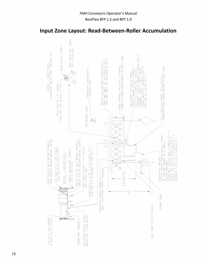
Input Zone Layout: Read-Between-Roller Accumulation
FMH Conveyors Operator’s ManualBestFlex BFP 1.5 and BFP 1.9

19
Input Zone Parts List: Read-Between-Roller Accumulation
Note: ZZ is determined by the unit width and will either be 18, 24, or 30. So, for a BFP1.5 conveyor with that is 24-incheswide, your roller number will be 50098-24 and your axle number will be 95037-24.
1-90049 1 Circuit Board, 2-Way Accum. 15094 1 Terminal Strip, 3-Pole
15109 1 Circuit Board, Power Supply 11111 As Required Locknut, Nylon, 5/16
1-90056 4 Stand off, Plastic 12185 As Required Spacer, 3/4 OD x 13/32 ID x 0.20
1-90069 4 Spacer, 1/4 HEX x 3/4 LG 12187 As Required Washer, Nylon, 1" OD
15037-1 6 Ft. Electrical Cord, 14/3 SJ 300V 60081-PR As Required Leg Mount Bracket, 5" or
1-90055 1 Cable Control 26/8 60379-PR As Required Leg Mount Bracket, 4" or
1-90050 1 Enclosure Assembly, Circuit Board 60375 As Required Leg Mount Bracket, 3-1/2" or
300928 1 Enclosure, Power Supply 60295-PR As Required Leg Mount Bracket, 3"
1-90066 1 Control Board with Speed POT 60463-5 As Required Roller Mount Bracket, 5" or
1-90065 1 Knob/Dial Kit, KB Control 60463-4 As Required Roller Mount Bracket, 4" or
1-90067 1 Circuit Breaker, 15 Amp Service or 60463-35 As Required Roller Mount Bracket, 3-1/2" or
1-90076 1 Circuit Breaker, 20 Amp Service or 60463-3 As Required Roller Mount Bracket, 3"
1-90068 1 Circuit Breaker, 30 Amp Service 50098-ZZ As Required Roller 1.5 x ZZ* (SEE NOTE BELOW) or
10530-2 4 RHMS #10-24 x 3/4 50099-ZZ As Required Roller 1.9 x ZZ* (SEE NOTE BELOW)
11999 4 Washer, Flat, 3/16" 95037-ZZ As Required Axle 12mm x ZZ* Length, 5/16 THD
12120 4 Washer, Lock, 3/16" 10024 As Required Screw, HHC 5/16-18 x 1/2
11279-1 4 Nut, HEX #10-32 007003 1 Motor, 180V, DC 1/8 HP (0-120 FPM) or
300101 3 Photo-Eye Sensor Diffuse 007003 1 Motor, 90V, DC 1/8 HP (0-200 FPM)
60102-1 1 Tray Mount Bracket, PE, LH 96504 1 Bracket Motor Mount
60102-2 1 Tray Mount Bracket, PE, RH 60405 4 Brace Motor Mount
96510 2 Offset Leg Mount Bracket 10000 2 Screw, HHC 1/4-20 x 5/8
60101-18 1 Photo-Eye Mount Tray, 18" or 11110 2 Locknut, 1/4-20 Nylon
60101 1 Photo-Eye Mount Tray, 24" or 10052 6 Screw, HHC 3/8-16 x 2
60101-30 1 Photo-Eye Mount Tray, 30" 11130 6 Locknut, 3/8-16 Nylon
1-90019 3 Strain Relief, .250 Cable 019910 1 Pulley, Drive, Double Groove
12000 4 Washer, Flat, 1/4" 19007 As Required Pulley, Idler, Double Groove
11110 6 Locknut, Nylon, 1/4" 60406 As Required Idler Mount Bracket
3000073 1 Start/Stop Motor Control 12466 2 Drive Belt
15037 3 Ft. Electrical Cord, 16/2 SO 12467 As Required Idler Belt
15019 1 Plug/Cord M 12/3 300V 3' or 1-90049-S 1 Accumulation Schematic
15024-30 1 Male Power Plug, 30 Amp plus 10015 2 Screw, HHC 1/4-20 x 1-3/4"
15037-7 3 Ft. Electrical Cord, 10/3 (30-AMP Only) 10534 4 Bolt, HHC 1/4-20 x 1/2"
1-90070 1 Strain Relief, 7P2 15025 25 Cable Tie, 3/8L, 3/16W
1-90071 3 Strain Relief, #MP30-1 15030-3 8 Screw, #8-32X3/8 RHM
1-90072 2 Strain Relief, MP4K1 15045-15 1 Fuse, 15 Amp, 250V Ceramic
15012-1 3 Strain Relief, 16/3 Wire 15097 4 1/2" Cable Clamp Hanger
15015 7 Terminal Fork #10, Stud 16-14GAB 15098 8 Nylon Axle Clamp
60492 As Required Sidebar, BFP15 or 15109-S 1 Power Supply Schematic
60507 As Required Sidebar, BFP19 60440 1 Strap, Enclosure Support
10600 As Required Sidebar Bolt, 3/8 x 3/8, 5/16 THD 15030-5 2 Screw, #8-32 X 1
10620 As Required Sidebar Bolt, 3/8 x 0.70, 5/16 THD 11279 2 Nut, #8-32
10624 As Required Sidebar Bolt, 3/8 x 1.10, 5/16 THD
FMH Conveyors Operator’s ManualBestFlex BFP 1.5 and BFP 1.9

20
Middle Zone Layout: Read-Between-Roller Accumulation
FMH Conveyors Operator’s ManualBestFlex BFP 1.5 and BFP 1.9

21
Middle Zone Parts List: Read-Between-Roller Accumulation
Note: ZZ is determined by the unit width and will either be 18, 24, or 30. So, for a BFP1.5 conveyor with that is 24-incheswide, your roller number will be 50098-24 and your axle number will be 95037-24.
1-90049 1 Circuit Board, 2-Way Accum. 60295-PR As Required Leg Mount Bracket, 3"
1-90056 4 Stand off, Plastic 15094 1 Terminal Strip, 3-Pole
15037-1 6 Ft. Electrical Cord, 14/3 SJ 300V 60463-5 As Required Roller Mount Bracket, 5" or
1-90055 1 Cable Control 26/8 60463-4 As Required Roller Mount Bracket, 4" or
1-90050 1 Enclosure Assembly, Circuit Board 60463-35 As Required Roller Mount Bracket, 3-1/2" or
1-90081 1 Enclosure Cover 60463-3 As Required Roller Mount Bracket, 3"
1-90152 1 Thumb Screw, #8-32 50098-ZZ As Required Roller 1.5 x ZZ* (SEE NOTE BELOW) or
1-90153 1 Nut, U-Clip, #8-32 50099-ZZ As Required Roller 1.9 x ZZ* (SEE NOTE BELOW)
300101 3 Photo-Eye Sensor Diffuse 95037-ZZ As Required Axle 12mm x ZZ* Length, 5/16 THD
60102-1 1 Tray Mount Bracket, PE, LH 10024 As Required Screw, HHC 5/16-18 x 1/2
60102-2 1 Tray Mount Bracket, PE, RH 007003 1 Motor, 180V, DC 1/8 HP (0-120 FPM) or
96510 2 Offset Leg Mount Bracket 007003 1 Motor, 90V, DC 1/8 HP (0-200 FPM)
60101-18 1 Photo-Eye Mount Tray, 18" or 96504 1 Bracket Motor Mount
60101 1 Photo-Eye Mount Tray, 24" or 60405 4 Brace Motor Mount
60101-30 1 Photo-Eye Mount Tray, 30" 10000 2 Screw, HHC 1/4-20 x 5/8
12000 2 Washer, Flat, 1/4" 11110 2 Locknut, 1/4-20 Nylon
11110 2 Locknut, Nylon, 1/4" 10052 6 Screw, HHC 3/8-16 x 2
1-90070 1 Strain Relief, 7P2 11130 6 Locknut, 3/8-16 Nylon
1-90071 3 Strain Relief, #MP30-1 019910 1 Pulley, Drive, Double Groove
1-90072 2 Strain Relief, MP4K1 19007 As Required Pulley, Idler, Double Groove
15012-1 3 Strain Relief, 16/3 Wire 60406 As Required Idler Mount Bracket
15015 7 Terminal Fork #10, Stud 16-14GAB 12466 2 Drive Belt
60492 As Required Sidebar, BFP15 or 12467 As Required Idler Belt
60507 As Required Sidebar, BFP19 1-90049-S 1 Accumulation Schematic
10600 As Required Sidebar Bolt, 3/8 x 3/8, 5/16 THD 10015 2 Screw, HHC 1/4-20 x 1-3/4"
10620 As Required Sidebar Bolt, 3/8 x 0.70, 5/16 THD 10534 4 Bolt, HHC 1/4-20 x 1/2"
10624 As Required Sidebar Bolt, 3/8 x 1.10, 5/16 THD 15025 25 Cable Tie, 3/8L, 3/16W
11111 As Required Locknut, Nylon, 5/16 15030-3 8 Screw, #8-32X3/8 RHM
12185 As Required Spacer, 3/4 OD x 13/32 ID x 0.20 15097 4 1/2" Cable Clamp Hanger
12187 As Required Washer, Nylon, 1" OD 15098 8 Nylon Axle Clamp
60081-PR As Required Leg Mount Bracket, 5" or 15030-5 2 Screw, #8-32 X 1
60379-PR As Required Leg Mount Bracket, 4" or 11279 2 Nut, #8-32
60375 As Required Leg Mount Bracket, 3-1/2" or
FMH Conveyors Operator’s ManualBestFlex BFP 1.5 and BFP 1.9

22
Last Zone Layout: Read-Between-Roller Accumulation
FMH Conveyors Operator’s ManualBestFlex BFP 1.5 and BFP 1.9

23
Last Zone Parts Lists: Read-Between-Roller Accumulation
Note: ZZ is determined by the unit width and will either be 18, 24, or 30. So, for a BFP1.5 conveyor with that is 24-incheswide, your roller number will be 50098-24 and your axle number will be 95037-24.
1-90049 1 Circuit Board, 2-Way Accum. 15030-5 2 Screw, #8-32 X 1
1-90012 1 Interface Board 11279 2 Nut, #8-32
1-90069 4 Spacer, 1/4 HEX x 3/4 Leg 60081-PR As Required Leg Mount Bracket, 5" or
15037-1 6 Ft. Electrical Cord, 14/3 SJ 300V 60379-PR As Required Leg Mount Bracket, 4" or
1-90055 1 Cable Control 26/8 60375 As Required Leg Mount Bracket, 3-1/2" or
1-90059 1 Enclosure 60295-PR As Required Leg Mount Bracket, 3"
1-90056 4 Stand off, Plastic 60463-5 As Required Roller Mount Bracket, 5" or
1-90050 1 Enclosure Assembly, Circuit Board 60463-4 As Required Roller Mount Bracket, 4" or
300101 3 Photo-Eye Sensor Diffuse 60463-35 As Required Roller Mount Bracket, 3-1/2" or
60102-1 1 Brkt, Tray Mnt, Photoeye, LH 60463-3 As Required Roller Mount Bracket, 3"
60102-1 1 Brkt, Tray Mnt, Photoeye, LH 50098-ZZ As Required Roller 1.5 x ZZ* (SEE NOTE BELOW) or
96510 2 Offset Leg Mount Bracket 50099-ZZ As Required Roller 1.9 x ZZ* (SEE NOTE BELOW)
60101-18 1 Photo-Eye Mount Tray, 18" or 95037-ZZ As Required Axle 12mm x ZZ* Length, 5/16 THD
60101 1 Photo-Eye Mount Tray, 24" or 10024 As Required Screw, HHC 5/16-18 x 1/2
60101-30 1 Photo-Eye Mount Tray, 30" 007003 1 Motor, 180V, DC 1/8 HP (0-120 FPM) or
1-90019 3 Strain Relief, .250 Cable 007003 1 Motor, 90V, DC 1/8 HP (0-200 FPM)
12000 4 Washer, Flat, 1/4" 96504 1 Bracket Motor Mount
11110 6 Locknut, Nylon, 1/4" 60405 4 Brace Motor Mount
3000073 1 Start/Stop Motor Control 10000 2 Screw, HHC 1/4-20 x 5/8
15037-11 3 Ft. Electrical Cord, 18/2 11110 2 Locknut, 1/4-20 Nylon
1-90070 1 Strain Relief, 7P2 10052 6 Screw, HHC 3/8-16 x 2
1-90071 3 Strain Relief, #MP30-1 11130 6 Locknut, 3/8-16 Nylon
1-90072 2 Strain Relief, MP4K1 019910 1 Pulley, Drive, Double Groove
15012-1 3 Strain Relief, 16/3 Wire 19007 As Required Pulley, Idler, Double Groove
15015 7 Terminal Fork #10, Stud 16-14GAB 60406 As Required Idler Mount Bracket
60492 As Required Sidebar, BFP15 or 12466 2 Drive Belt
60507 As Required Sidebar, BFP19 12467 As Required Idler Belt
10600 As Required Sidebar Bolt, 3/8 x 3/8, 5/16 THD 1-90049-S 1 Accumulation Schematic
10620 As Required Sidebar Bolt, 3/8 x 0.70, 5/16 THD 10015 2 Screw, HHC 1/4-20 x 1-3/4"
10624 As Required Sidebar Bolt, 3/8 x 1.10, 5/16 THD 10534 4 Bolt, HHC 1/4-20 x 1/2"
11111 As Required Locknut, Nylon, 5/16 15025 25 Cable Tie, 3/8L, 3/16W
12185 As Required Spacer, 3/4 OD x 13/32 ID x 0.20 15030-3 8 Screw, #8-32X3/8 RHM
12187 As Required Washer, Nylon, 1" OD 15097 4 1/2" Cable Clamp Hanger
15094 1 Terminal Strip, 3-Pole 15098 8 Nylon Axle Clamp
FMH Conveyors Operator’s ManualBestFlex BFP 1.5 and BFP 1.9

24
Electrical Connection Diagrams
FMH Conveyors Operator’s ManualBestFlex BFP 1.5 and BFP 1.9
25
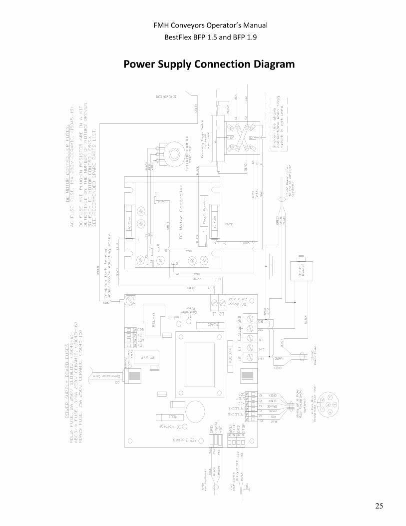
Power Supply Connection Diagram
FMH Conveyors Operator’s ManualBestFlex BFP 1.5 and BFP 1.9

26
Zone Connection Diagram
FMH Conveyors Operator’s ManualBestFlex BFP 1.5 and BFP 1.9
27
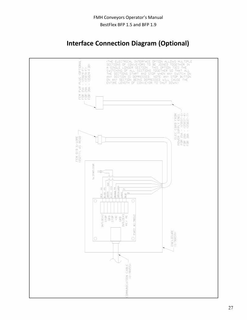
Interface Connection Diagram (Optional)
FMH Conveyors Operator’s ManualBestFlex BFP 1.5 and BFP 1.9

28
Receiving Interface Connection (Optional)
FMH Conveyors Operator’s ManualBestFlex BFP 1.5 and BFP 1.9

29
Recommended Spare Parts List
PartNumberDescriptionQtyPart NumberDescriptionQty007003Motor,180V, 250RPM, Best (Std 0‐120 fpmunits)160507Sidebar, 2 x 8‐5/81070247Motor, 180V, 250RPM, Baldor (Units priortoOct 2012150099‐18Roller, 1.90 x 18 ( for 18‐inch wide units) or21‐90049Circuit Board, 2‐way Accumulation150099‐24Roller, 1.90 x 24 ( for 24‐inch wide units) or215109PowerSupply Board150099‐30Roller, 1.90 x 30 ( for 30‐inch wide units) or2
15045‐15Fuse,15A,250V, Ceramic, (Pwr & KB CntrlBrd,15A)315045‐6Fuse,2A,250V, SloBlo, (Pwr Supply Brd, 2A)215045‐16Fuse,15A,250V, Ceramic, (Pwr Supply Brd,3/4A)2Part NumberDescriptionQty12543Fuse,1‐1/4A, 250V, 1/4 x 1‐1/4, (Accum. Board)412549Kit,Resistor‐Fuse, .05 Ohm 4A (2 to 3 motors)11‐90066Control Board, KB Motor, Spd Pot112548Kit,Resistor‐Fuse, .035 Ohm 5A (4 motors)11‐90055Cable,Control, 26‐8 Coiled212547Kit,Resistor‐Fuse, .025 Ohm 8A (5 to 7 motors)112466Belt,Drive (Orange)1212546Kit,Resistor‐Fuse, .015 Ohm 12A (8 to 11 motors)112467Belt,Idler (Clear)3012544Kit,Resistor‐Fuse, .01 Ohm 15A (12 to 14 motors)110620Bolt,Shldr, 3/8 x .700, 5/16‐181012545Kit,Resistor‐Fuse, .006 Ohm 15A (15 to 16 motors)110600Bolt,Shldr, 3/8 x .356, 5/16‐181010624Bolt,Shldr, 3/8 x 1.10, 5/16‐181011122Nut,NylJam, 5/16‐181212549Kit,Resistor‐Fuse, .05 Ohm 4A (2 to 4 motors)112185Spacer, Nyl, 3/4OD x 13/32ID x .2002012548Kit,Resistor‐Fuse, .035 Ohm 5A (5 motors)112187Washer, Nyl, 1OD x 13/32ID x 1/162012547Kit,Resistor‐Fuse, .025 Ohm 8A (6 to 8 motors)1
12546Kit, Resistor‐Fuse, .015 Ohm 12A (9 to 12 motors)112544Kit, Resistor‐Fuse, .01 Ohm 15A (13 to 15 motors)1
300101Photoeye, Barrel Optic, DC, NPN, Diffused312545Kit,Resistor‐Fuse, .006 Ohm 15A (16 motors)1
Note:15096Photoeye, Reflective Sensor, NPN1TheResistor‐Fuse Kit needed is determined by the numberof motors1‐90027Reflector, Photoeye, 1‐1/4 Dia1beingdriven by the KB Motor Control Board (p/n 1‐90066).Each15095Cable,QD, 6ft1KBController can drive up to 16 motors. Longer conveyorswill
will require multipe KB controllers. Each KB controller willhave aresistor‐fuse kit based upon the number of motors that particular
PartNumberDescriptionQtycontroller is driving.60492Sidebar, 1‐19/32 x 8‐5/810
50098‐18Roller, 1.51 x 18 ( for 18‐inch wide units) or250098‐24Roller, 1.51 x 24 ( for 24‐inch wide units) or250098‐30Roller,1.51 x 30 ( for 30‐inch wide units) or2
BFP1.5 Specific Parts
Resistor Fuse Kits, Best Motor Units (See Note Below)
Leg‐Mounted Reflective Optics
Items Common to all UnitsBFP1.9 Specific Parts
Resistor Fuse Kits, Baldor Motor Units (See NoteBelow)
Optic PartsRead‐Between‐the Roller (RBR) Optics
FMH Conveyors Operator’s ManualBestFlex BFP 1.5 and BFP 1.9