
Best Practice Catalogue on Successful Running Solar Air...
66
Best Practice Catalogue on Successful Running Solar Air-Conditioning Appliances
Transcript of Best Practice Catalogue on Successful Running Solar Air...

Best Practice Catalogue on Successful Running Solar Air-Conditioning Appliances

EIE/06/034/SI2.446612 SOLAIR
Work package 2: Market review and analysis of small and medium sized solar air-conditioning (SAC) applications
Task 2.2: Preparation of a web based database of best available examples
Best Practice Catalogue
June 30, 2008
Version 1.0
1 Introduction............................................................................. 3 2 Technologies............................................................................ 4
2.1 Chilled water systems.................................................... 6 2.2 Open cycle processes .................................................... 9 2.3 Solar thermal collectors ............................................... 11
3 SOLAIR database of solar cooling and air-conditioning.................. 12 4 SOLAIR Best Practice Examples ................................................ 13
4.1 Best Practice Examples: AUSTRIA ................................. 14 4.2 Best Practice Examples: FRANCE................................... 21 4.3 Best Practice Examples: GERMANY ................................ 28 4.4 Best Practice Examples: GREECE................................... 42 4.5 Best Practice Examples: ITALY...................................... 47 4.6 Best Practice Examples: PORTUGAL............................... 53 4.7 Best Practice Examples: SPAIN ..................................... 57
5 Solar cooling: examples on advanced approaches........................ 62

WP2 Preparation of a web based database of best available examples Best Practice Catalogue
2
This report was edited by: Edo Wiemken, Fraunhofer ISE
SOLAIR is co-ordinated by
target GmbH, Germany
Partners in the SOLAIR consortium:
AEE – Institute for Sustainable Technologies, Austria
Fraunhofer Institute for Solar Energy Systems ISE, Germany
Instituto Nacional de Engenharia, Technologia e Innovação INETI, Portugal
Politecnico di Milano, Italy
University of Ljubljana, Slovenia
AIGUASOL, Spain
TECSOL, France
Federation of European Heating and Air-conditioning Associations RHEVA, The Netherlands
Centre for Renewable Energy Sources CRES, Greece
Ente Vasco de la Energia EVE, Spain
Provincia di Lecce, Italy
Ambiente Italia, Italy
SOLAIR is supported by
The sole responsibility for the content of this report lies with the authors. It does not necessarily reflect the opinion of the European Communities. The European Commission is not responsible for any use that may be made of the information contained therein

WP2 Preparation of a web based database of best available examples Best Practice Catalogue
3
1 Introduction
In nearly all European countries, a strong increase in the demand for building cooling and air-conditioning is detected and predicted for the following decades. The reasons for this general increase are manyfold, such as an increase in comfort habits, currently still low energy costs, architectural trends like an increased fraction of glazed areas in buildings and last but not least slowly changing climate conditions. This rising demand for cooling and air-conditioning in buildings involves unfavourable fossil fuel consumptions as well as upcoming stability problems in the electrictity supply in mediterraenean countries, which in turn demands for costly upgradings of the grids to handle electricity peak power demand situations.
Thus, improved building concepts, targeting on reduction of cooling loads by passive and innovative measures, and the use of alternatives in coverage the remaining cooling demands of buildings, are of interest. Solar driven or assisted cooling is one of the possibilities to provide acively cold.
In the context of the SOLAIR project, solar cooling or solar air-conditioning is used for solar thermally driven processes. Solar cooling in this sense may con-tribute to
- replacement of fossil fuel demand by use of solar heat and by this, contributing to the European policy targets on the increased use of renewable energies;
- reduction of greenhouse effect emmissions through both, savings in primary energy and avoidance of environmental harmful refrigerants;
- support in stability of electricity grids by less electrictiy energy and peak-power demand;
- optimized use of solar thermal systems through use of solar heat for combined assistance of space heating, cooling and domestic hot water preparation.
The SOLAIR project provides several materials on solar cooling, adressing different levels on information. Within this catalogue, Best Practice examples from the SOLAIR database are presented. Many of this examples went into operation less than one or two years before the compilation of this catalogue, long term operation experience can not be expected so far. Thus, the definition ‘Best Practice’ refers here to an appropriate system concept and to promising approaches of solar cooling. The catalogue aims to present the applicability of solar cooling technologies within different building environments, at different locations and with different technical solutions. In the beginning, a brief review on solar cooling technologies is presented.
More information on the SOLAIR database is provided in the Cross-country report of the review of available technical solutions and successful running systems, prepared in SOLAIR and accessible at www.solair-project.eu.

WP2 Preparation of a web based database of best available examples Best Practice Catalogue
4
2 Technologies
The focus in SOLAIR is on solar cooling and air-conditioning systems in the small and medium size capacity range. The classification into ‘small’ and ‘medium’ aligns with available chiller products; small applications are in this sense systems with a nominal chilling capacity below 20 kW, and medium size systems may range up to approx. 100 kW.
Systems in the small capacity range are usually consist of thermally driven chil-led water systems, whereas medium sized systems may be open cycle desiccant evaporative (DEC) cooling systems as well. While in the first type of system tech-nology the distribution medium is chilled water in a closed loop to remove the loads from the building, in the latter one supply air is directly handled in humi-dity and temperature respectively in an open process. Figure 2.1 visualises the two general types of applications. Of course, applications using both types of technology at the same time are possible. In chilled water systems, the central cold water distribution grid may serve decentralised cooling units such as fan coils (mostly with dehumidification), chilled ceilings, walls or floors; but the chil-led water may be used for supply air cooling in a central air handling unit as well. The required chilled water temperature depends on this type of usage and is important for the system design and configuration, but the end-use devices are not in the focus of SOLAIR and thus are not presented more in detail.
Figure 2.2 illustrates that any thermally driven cooling process operates at three different temperature levels: with driving heat Qheat supplied to the process at a temperature level of TH , heat is removed from the cold side thereby producing the useful ‘cold’ Qcold at temperature TC. Both amounts of heat are to be rejected (Qreject) at a medium temperature level TM. The driving heat Qheat may be pro-vided by an appropriate designed solar thermal collector system, either alone or in combination with auxiliary heat sources.
While in open cycle processes the heat rejection is with the air flow in the system integrated into the process, closed chilled water processes require for an external heat rejection system, e.g., a cooling tower. The type of the heat rejection system is currently turning more into the field of vision, as this component usu-ally is responsible for a considerable fraction of the remaining energy consump-tion of solar cooling systems.
A basic number to quantify the thermal process quality is the coefficient of per-formance COP, defined as COP = Qcold / Qheat , thus indicating the amount of required heat per unit ‘produced’ cold (more accurately: per unit removed heat). The COP and the chilling capacity depends strongly on the temperature levels of TH, TC and TM. This dependency is discussed more in detail in e.g. [Henning, 2006].
In market available products of thermally driven chillers, the COP ranges at rated operation conditions from 0.5 to 0.8 in single-effect machines and up to 1.2 in double-effect machines.

WP2 Preparation of a web based database of best available examples Best Practice Catalogue
5
In open cycle desiccant cooling systems, the COP is more difficult to assess, since it depends more strongly on the system operation. It is useful, to define here the COP for the desiccant operation mode only, since in this operation mode heat is required. Experiences from DEC plants have shown that COP values comparatively to single-effect chillers may be achieved.
Cooled / Conditionedarea
Chilled ceiling
Supply air
Fan coil
~18°C
16°C - 18°C(< 12°C)
6°C - 9°C
Chilled watertemperature
Heat> 60°C
Thermally drivenChiller
Supply air
Heat> 50°C
Return air
Desiccant evaporative cooling (DEC)
Conditionedarea
Figure 2.1 General types of thermally driven cooling and air-conditioning technologies. In the figure above, chilled water is produced in a closed loop for different decentral applications or for supply air cooling. In the figure below, supply air is directly cooled and dehumidified in an open cycle process. Source: Fraunhofer ISE. The technologies are outlined more in detail below. Heat is required in both technologies, to allow a coninuous system operation. In the applications surveyed in SOLAIR, the heat is at least to a significant part produced by a solar thermal collector system.
Qcold
Qreject
Qheat
TC
TM
TH
Figure 2.2 Basic scheme of a thermally driven cooling process.

WP2 Preparation of a web based database of best available examples Best Practice Catalogue
6
2.1 Chilled water systems
Absorption chillers
The dominating technology of thermally driven chillers is based on absorption. The basic physical process consists of at least two chemical components, one of them serving as refrigerant and the other as the sorbent. The main components of an absorption chiller are shown in figure 2.3. The process is well documented, e.g., in [ASHRAE, 1988]; thus, details will be not presented here.
The majority of absorption chillers use water as refrigerant and liquid lithium-bromide as sorbent. Typical chilling capacities are in the range of several hun-dred kW. Mainly, they are supplied with waste heat, district heat or heat from co-generation. The required heat source temperature is usually above 85°C and typical COP values are between 0.6 and 0.8. Until a few years ago, the smallest machine available was a Japanese product with a chilling capacity of 35 kW.
Double-effect machines with two generators require for higher driving tempe-ratures > 140°C, but show higher COP values of > 1.0. The smallest available chiller of this type shows a capacity of approx. 170 kW. With respect to the high driving temperatures, this technology demands in combination with solar thermal heat for concentrating collector systems. This is an option for climates with high fractions of direct irradiation.
chilled watercooling water
cooling waterhot water
(driving heat)
GENERATOR
ABSORBER
CONDENSER
EVAPORATOR
chilled watercooling water
cooling waterhot water
(driving heat)
GENERATOR
ABSORBER
CONDENSER
EVAPORATOR
Figure 2.3 Scheme of a thermally driven absorption chiller. Compared to a conventional electrically driven compression chiller, the mechanical compression unit is replaced by a ‘thermal compression’ unit with absorber and generator. The cooling effect is based on the evaporation of the refrigerant (e.g., water) in the evaporator at low pressure. Due to the properties of the phase change, high amounts of energy can be transferred. The vaporised refrigerant is absorbed in the absorber, thereby diluting the refrigerant/sorbent solution. Cooling is necessary, to run the absorption process efficient. The solution is continuousely pumped into the generator, where the regeneration of the solution is achieved by applying driving heat (e.g., hot water). The refrigerant leaving the generator by this process condenses through the application of cooling water in the condenser and circulates by means of an expansion valve again into the evaporator.

WP2 Preparation of a web based database of best available examples Best Practice Catalogue
7
Figure 2.4a Examples of small absorption chillers using water as refrigerant and Lithium-Bromide as sorption fluid. Left: air-cooled chiller with a capacity of 4.5 kW of the Spanish manufacturer Rotartica. Middle: 10 kW Chiller with high part-load efficiency and overall high COP of the German manufacturer Sonnenklima. Right: Chiller with 15 kW capacity, manufactured by the German company EAW; this machine is also available in capacities of 30 kW, 54 kW, 80 kW and above. Sources: Rotartica, Sonnenklima, EAW.
Figure 2.4b Further examples of absorption chillers. Left: Ammonia-water Absorption chiller with 12 kW chilling capacity of the Austrian company Pink. Middle: This chiller uses water as refrigerant and Lithium-Chloride as sorption material. The crystallisation phase of the sorption material is also used, effecting in an internal energy storage. The capacity is approx. 10 kW; the machine is developed by ClimateWell, Sweden, and can operate as heat pump as well. Right: Absorption chiller with the working fluid H2O/LiBr and a capacity of 35 kW from Yazaki, Japan. This chiller is often found in solar cooling systems, since it was for several years the smallest in Europe available absorption chiller, appli-cable with solar heat. Currently, a smaller version with 17.5 kW chiller capacity from this manufacturer has entered the European market. Sources: Pink, ClimateWell, Yazaki.
Recently, the situation has changed due to a number of new chiller products in the small and medium capacity range, which have entered the market. In ge-neral, they are designed to be operated with low driving temperatures and thus

WP2 Preparation of a web based database of best available examples Best Practice Catalogue
8
applicable for stationary solar thermal collectors. The lowest chiller capacity avai-lable is now 4.5 kW. Some examples of small and medium size absorption chillers are given in figure 2.4. In addition to the traditional working fluids H2O/LiBr, also H2O/LiCl and NH3/H2O are applied. The application of the latter working fluid with Ammonia as refrigerant ist relatively new for building cooling, as this technology was dominantly used for industrial refrigeration purposes be-low 0°C in large capacities. An advantage of this chiller type is especially given in applications, where a high temperature lift (TM – TC) is necessary. This is for example the case in areas with water shortage, when dry cooling at high ambient temperatures has to be applied.
Adsorption chillers
Beside processes using a liquid sorbent, also machines using solid sorption ma-terials are available. This material adsorbs the refrigerant, while it releases the refrigerant under heat input. A quasi-continuous operation requires for at least two compartments with sorption material. Figure 2.5 shows the components of an adsorption chilller. Market available systems use water as refrigerant and silica gel as sorbent, but R&D on systems using zeolithes as sorption material is ongoing.
cooling water
cooling water
chil led water
hot water(driving heat)
CONDENSER
EVAPORATOR
12
Figure 2.5 Scheme of an adsorption chiller. They consist basically of two sorbent com-partments 1 and 2, and the evaporator and condenser. While the sorbent in the first compartment is desorbing (removal of adsorbed water) using hot water from the external heat source, e.g. the solar collector, the sorbent in the second compartment adsorbs the refrigerant vapour entering from the evaporator; this compartment has to be cooled in order to increase the process efficiency. The refrigerant, condensed in the cooled con-denser and transferred into the evaporator, is vaporised under low pressure in the eva-porator. Here, the useful cooling is produced. Periodically, the sorbent compartment are switched over in their functions from adsorption to desorption. This is usually done through a switch control of external located valves.
To date, only few manufacturers from Japan, China and from Germany produce adsorption chillers; a German company is with a small unit of 5.5 kW capacity on the market since 2007 and has increased the rated capacity in an improved version to 7.5 kW (model of 2008). Typical COP values of adsorption chillers are
WP2 Preparation of a web based database of best available examples Best Practice Catalogue
9
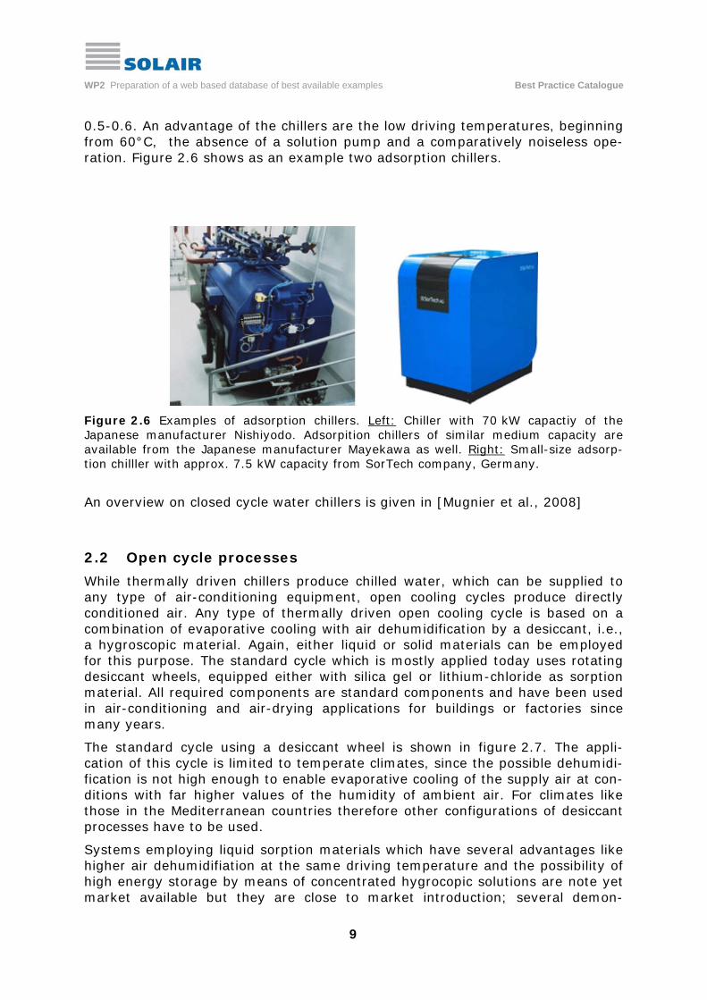
0.5-0.6. An advantage of the chillers are the low driving temperatures, beginning from 60°C, the absence of a solution pump and a comparatively noiseless ope-ration. Figure 2.6 shows as an example two adsorption chillers.
Figure 2.6 Examples of adsorption chillers. Left: Chiller with 70 kW capactiy of the Japanese manufacturer Nishiyodo. Adsorpition chillers of similar medium capacity are available from the Japanese manufacturer Mayekawa as well. Right: Small-size adsorp-tion chilller with approx. 7.5 kW capacity from SorTech company, Germany.
An overview on closed cycle water chillers is given in [Mugnier et al., 2008]
2.2 Open cycle processes
While thermally driven chillers produce chilled water, which can be supplied to any type of air-conditioning equipment, open cooling cycles produce directly conditioned air. Any type of thermally driven open cooling cycle is based on a combination of evaporative cooling with air dehumidification by a desiccant, i.e., a hygroscopic material. Again, either liquid or solid materials can be employed for this purpose. The standard cycle which is mostly applied today uses rotating desiccant wheels, equipped either with silica gel or lithium-chloride as sorption material. All required components are standard components and have been used in air-conditioning and air-drying applications for buildings or factories since many years.
The standard cycle using a desiccant wheel is shown in figure 2.7. The appli-cation of this cycle is limited to temperate climates, since the possible dehumidi-fication is not high enough to enable evaporative cooling of the supply air at con-ditions with far higher values of the humidity of ambient air. For climates like those in the Mediterranean countries therefore other configurations of desiccant processes have to be used.
Systems employing liquid sorption materials which have several advantages like higher air dehumidifiation at the same driving temperature and the possibility of high energy storage by means of concentrated hygrocopic solutions are note yet market available but they are close to market introduction; several demon-

WP2 Preparation of a web based database of best available examples Best Practice Catalogue
10
stration projects are carried out in order to test applicability of this technology for solar assisted air conditioning. A possible general scheme of a liquid desiccant cooling system is shown in figure 2.8.
humidifier cooling loads
supply air
backupheater
return air
dehumidifier wheel
heat recovery wheel
1 2 3 4 56
789101112
Figure 2.7 Scheme of a solar thermally driven solid Desiccant Evaporative Cooling system (DEC), using rotating sorption and heat recovery wheels (source: Fraunhofer ISE) and below: sketch of the DEC unit (source: Munters). The successive processes in the air stream are as follows: 1 2 sorptive dehumidification of supply air; the process is almost adiabatic and the air
is heated by the adsorption heat released in the matrix of the sorption wheel 2 3 pre-cooling of the supply air in counter-flow to the return air from the building 3 4 evaporative cooling of the supply air to the desired supply air humidity by means
of a humidifier 4 5 the heating coil is used only in the heating season for pre-heating of air 5 6 small temperature increase, caused by the fan 6 7 supply air temperature and humidity are increased by means of internal loads 7 8 return air from the building is cooled using evaporative cooling close to the
saturation line 8 9 the return air is pre-heated in counter-flow to the supply air by means of a high
efficient air-to-air heat exchanger, e.g. a heat recovery wheel 9 10 regeneration heat is provided for instance by means of a solar thermal collector
system 10 11 the water bound in the pores of the desiccant material of the dehumidifer wheel is
desorbed by means of the hot air 11 12 exhaust air is blown to the environment by means of the return air fan.

WP2 Preparation of a web based database of best available examples Best Practice Catalogue
11
diluted solution
concentratedsolution
regeneration air
⇐ QH driving heat
⇒ QM rejected heat
Regenerator
Absorber
supply air
solution storage
LiCl/water
Figure 2.8 General scheme of a liquid desiccant cooling system. The supply air is dehumidified in a special configured spray zone of the absorber, where a concentrated salt solution is diluted by the humidity of the supply air. The process efficiency is increa-sed through heat rejection of the sorption heat, eg., by means of indirect evaporative cooling of the return air and heat recovery. A subsequent evaporative cooling of the sup-ply air may be applied, if necessary (heat recovery and evaporative cooling is not shown in the figure). In a regenerator, heat e.g. from a solar collector is applied, to concentrate the solution again. The concentrated and diluted solution may be stored in high energy storages, thus allowing a decoupling in time between cooling and regeneration to a cer-tain extent. Source: Fraunhofer ISE. In general, desiccant cooling systems are an interesting option if centralized ventilation systems are used. At sites with high latent and sensible cooling loads, the air-conditioning process can be splitted into dehumidification by means of a thermally driven open cycle desiccant process, and an additional chilled water system to maintain the sensible loads by means of e.g. chilled ceilings with high chilled water temperatures, in order to increase the efficiency of the chilled water production. More details on open cycle processes are given in [Henning, 2004/2008] and in [Beccali, 2008].
2.3 Solar thermal collectors
A broad variety of solar thermal collectors is available and many of them are applicable in solar cooling and air-conditioning systems. However, the appropri-ate type of the collector depends on the selected cooling technology and on the site conditions, i.e., on the radiation availability. General types of stationary col-lectors are shown in figure 2.9. The use of cost-effictive solar air collectors in flat plate construction is limited to desiccant cooling systems, since this technology requires the lowest driving temperatures (starting from approx. 50°C) and allows under special conditions the operation without thermal storage. To operate ther-mally driven chillers with solar heat, at least flat plate collectors of high quality (selective coating, improved insulation, high stagnation safety) are to be applied. Not shown in the figure are concentrating and tracked collectors, which may be applied to supply heat at a medium temperature level above 100°C and below

WP2 Preparation of a web based database of best available examples Best Practice Catalogue
12
200°C in order to drive e.g. double-effect chillers or ammonia-water chillers for a high temperature lift.
glas cover
insulation collector frameabsorber with air channels
glass cover
insulation collector frameabsorber with fluid channels
insulationcollector frame
glass cover
absorber with fluid channel
reflector
evacuated tube
optionally: reflector
evacuatedglass tube
Absorber with fluid channel (forward/return)
solar air collector
flat plate collector
CPC collector
evacuated tube collector
Figure 2.9 Examples of stationary collectors, applicable for solar cooling. Source: SOLAIR didactic material base / Fraunhofer ISE.
3 SOLAIR database of solar cooling and air-conditioning
Within SOLAIR, data from successful running applications on solar cooling and air-conditioning in the small and medium cooling capacity range were collected. Table 3.1 summarises briefly the content of this database. More details are given in the Cross-country analysis report of the database within SOLAIR [SOLAIR: Review technical solutions, 2008]. The Best Practice Examples, presented in the following section, are extracted from this database.

WP2 Preparation of a web based database of best available examples Best Practice Catalogue
13
Type of application Counts in
database
Technology Chilling capacity
range [kW]
Country
Hospital (& retired people building) 1 Ab 10 FR
Laboratory (for public hospital) 1 Ad 70 DE
Public library 1 DEC 81 ES
Public office 3 DECliq, DEC 11-30 DE, AT, PT
Other public 2 Ad, DEC 5.5-6 DE, GR
Commercial office 11 Ab 9-70 AT, FR, DE, GR, IT, PT, ES
Commercial seminar area 1 DEC 60 DE
Commercial wine storage 1 Ab 52 FR
Residential 3 Ab, Ad 4.5-10 AT, IT, ES
total: 24
Table 3.1 Type of application, technology, cooling capacity and distribution by coun-try of the sytems in the SOLAIR data base. Abbreviations: Ab = Absorption; Ad = Adsorption; DEC = Desiccant Evaporative Cooling; DECliq = liquid desiccant cooling.
4 SOLAIR Best Practice Examples
Many of the Best Practice examples presented in the following went into ope-ration less than one or two years before the compilation of this catalogue, long term operation experience can not be expected so far for this reason. Thus, the definition ‘Best Practice’ refers here to an appropriate system concept, successful operation and to advanced and promising approaches of solar cooling. The cata-logue aims to present the applicability of solar cooling technologies within diffe-rent building environments, at different locations and with different technical solutions.
The examples are transferred into this catalogue according to their presentation at the SOLAIR web page. In some examples, more information is available in an additional file, indicated right hand of the example and accessible for download from the web page.

WP2 Preparation of a web based database of best available examples Best Practice Catalogue
14
4.1 Best Practice Examples: AUSTRIA
Examples presented at the following pages:
1. Ökopark, Hartberg
2. Bachler, Gröbming
3. SOLution, Sattledt

WP2 Preparation of a web based database of best available examples Best Practice Catalogue
15
To be continued at the following page

WP2 Preparation of a web based database of best available examples Best Practice Catalogue
16
View at the Ökopark Hartberg, Austria

WP2 Preparation of a web based database of best available examples Best Practice Catalogue
17
To be continued at the following page

WP2 Preparation of a web based database of best available examples Best Practice Catalogue
18
Components of the Ammonia/Water chiller, installed at the Bachler system, Gröbming,
Austria. Source: PINK Energie- und Speichertechnik.

WP2 Preparation of a web based database of best available examples Best Practice Catalogue
19
To be continued at the following page

WP2 Preparation of a web based database of best available examples Best Practice Catalogue
20
Scheme of the solar cooling system at Sattledt, Austria

WP2 Preparation of a web based database of best available examples Best Practice Catalogue
21
4.2 Best Practice Examples: FRANCE
Examples presented at the following pages:
1. Résidence du Lac, Maclas
2. GICB building, Banyuls sur Mer
3. Kristal building, Saint Denis de la Réunion

WP2 Preparation of a web based database of best available examples Best Practice Catalogue
22
To be continued at the following page

WP2 Preparation of a web based database of best available examples Best Practice Catalogue
23
ScScheme of the solar cooling system at Maclas, France

WP2 Preparation of a web based database of best available examples Best Practice Catalogue
24
To be continued at the following page
WP2 Preparation of a web based database of best available examples Best Practice Catalogue
25

WP2 Preparation of a web based database of best available examples Best Practice Catalogue
26
To be continued at the following page

WP2 Preparation of a web based database of best available examples Best Practice Catalogue
27
Collector array and heat rejection unit of the Saint Denis de la Réunion solar cooling
system, France

WP2 Preparation of a web based database of best available examples Best Practice Catalogue
28
4.3 Best Practice Examples: GERMANY
Examples presented at the following pages:
1. Fraunhofer ISE, Freiburg
2. University Hospital, Freiburg
3. Chamber of Commerce ‘Südlicher Oberrhein’ (IHK-SO), Freiburg
4. Office building of Ott Ingenieure, Langenau
5. Solar Info Center SIC, Freiburg
6. Office building of IBA AG, Fürth

WP2 Preparation of a web based database of best available examples Best Practice Catalogue
29
To be continued at the following page

WP2 Preparation of a web based database of best available examples Best Practice Catalogue
30
Solar cooling system at Fraunhofer ISE in Freiburg, Germany. Top: cooling operation during summer. Bottom: heat pump operation during winter.

WP2 Preparation of a web based database of best available examples Best Practice Catalogue
31
To be continued at the following page

WP2 Preparation of a web based database of best available examples Best Practice Catalogue
32
Vacuum tubecollectors
81 m²
90 m²
Solarcircuit
Heatingcircuit 2
Heatingcircuit 1
Chilled water circuitprimary
Chilled water circuitsecondary
Coolingcircuit
Local steamnetwork
Solar heat storage
1 2 3
Water / air heat exchangerventilation system
Cold storage
Buf
fer s
tora
gefla
p by
pass
flap storage
Closed wetcooling tower
Adsorption chiller70 kW
A/C-supply valve
Winterheatingcircuit
Scheme of the solar cooling system at the University hospital laboratory building, Freiburg, Germany

WP2 Preparation of a web based database of best available examples Best Practice Catalogue
33
To be continued at the following page

WP2 Preparation of a web based database of best available examples Best Practice Catalogue
34
Scheme of the Desiccant Evaporativ Cooling (DEC) system at IHK-SO, Freiburg, Germany

WP2 Preparation of a web based database of best available examples Best Practice Catalogue
35
To be continued at the following page

WP2 Preparation of a web based database of best available examples Best Practice Catalogue
36
Heat production sub-system of the solar cooling system at Ott Ingenieure, Langenau,
Germany
WP2 Preparation of a web based database of best available examples Best Practice Catalogue
37
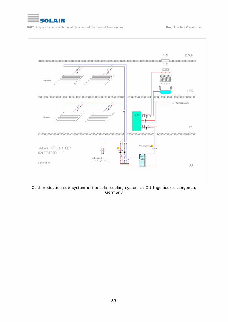
Cold production sub-system of the solar cooling system at Ott Ingenieure, Langenau,
Germany

WP2 Preparation of a web based database of best available examples Best Practice Catalogue
38
To be continued at the following page
Solar Info Center SIC, Freiburg, Germany

WP2 Preparation of a web based database of best available examples Best Practice Catalogue
39
Installed solar driven liquid desiccant evaporative cooling system and scheme of the
system at the Solar Infor Center (SIC), Freiburg, Germany

WP2 Preparation of a web based database of best available examples Best Practice Catalogue
40
To be continued at the following page

WP2 Preparation of a web based database of best available examples Best Practice Catalogue
41
Scheme of the solar cooling system at IBA AG, Fürth, Germany

WP2 Preparation of a web based database of best available examples Best Practice Catalogue
42
4.4 Best Practice Examples: GREECE
Examples presented at the following pages:
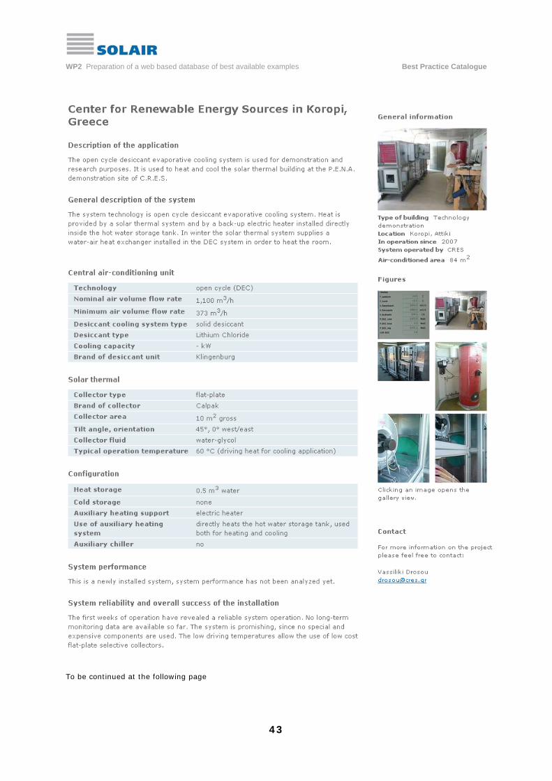
1. Center for Renewable Energy Sources, Koropi
2. Promitheus building – Sol Energy Offices, Palaio Faliro
WP2 Preparation of a web based database of best available examples Best Practice Catalogue
43
To be continued at the following page

WP2 Preparation of a web based database of best available examples Best Practice Catalogue
44
Scheme of the solar driven desiccant evaporative cooling system at Lavrio/Koropi, Greece

WP2 Preparation of a web based database of best available examples Best Practice Catalogue
45
To be continued at the following page

WP2 Preparation of a web based database of best available examples Best Practice Catalogue
46
Scheme of installations of the solar energy building in Palaio Faliro, Greece

WP2 Preparation of a web based database of best available examples Best Practice Catalogue
47
4.5 Best Practice Examples: ITALY
Examples presented at the following pages:
1. Manufacturing area, Bolzano
2. Residential building, Milan
3. ISI Pergine business center, Trento

WP2 Preparation of a web based database of best available examples Best Practice Catalogue
48
To be continued at the following page
WP2 Preparation of a web based database of best available examples Best Practice Catalogue
49
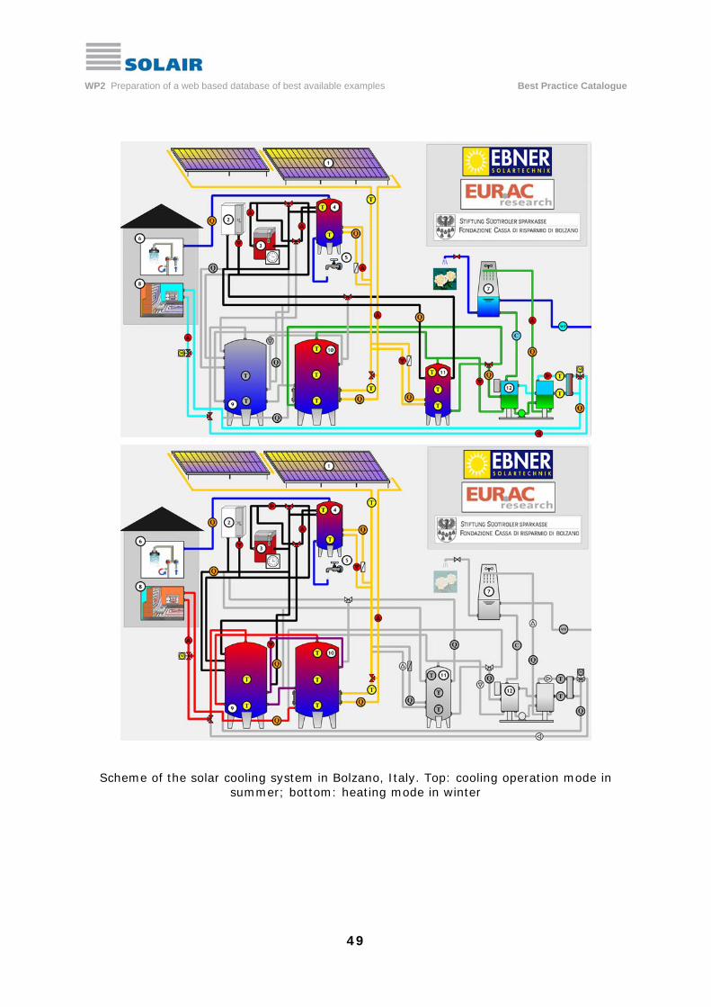
Scheme of the solar cooling system in Bolzano, Italy. Top: cooling operation mode in summer; bottom: heating mode in winter
WP2 Preparation of a web based database of best available examples Best Practice Catalogue
50

WP2 Preparation of a web based database of best available examples Best Practice Catalogue
51
To be continued at the following page

WP2 Preparation of a web based database of best available examples Best Practice Catalogue
52
Scheme of the cold production and cold distribution system at Trento, Italy

WP2 Preparation of a web based database of best available examples Best Practice Catalogue
53
4.6 Best Practice Examples: PORTUGAL
Examples presented at the following pages:
1. INETI building, Lisbon
2. Office building Vajra, Loulé

WP2 Preparation of a web based database of best available examples Best Practice Catalogue
54
To be continued at the following page

WP2 Preparation of a web based database of best available examples Best Practice Catalogue
55
Scheme of the desiccant evaporative cooling system (top) and of the solar / auxiliary
heating sub-system (bottom) at the Ineti building, Lisbon, Portugal

WP2 Preparation of a web based database of best available examples Best Practice Catalogue
56

WP2 Preparation of a web based database of best available examples Best Practice Catalogue
57
4.7 Best Practice Examples: SPAIN
Examples presented at the following pages:
1. Pompeu Fabra Library, Mataró
2. Headquarter building of CARTIF, Valladolid

WP2 Preparation of a web based database of best available examples Best Practice Catalogue
58
To be continued at the following page

WP2 Preparation of a web based database of best available examples Best Practice Catalogue
59
Scheme of the desiccant evaporative cooling system (DEC) in the public library at Mataró, Spain

WP2 Preparation of a web based database of best available examples Best Practice Catalogue
60
To be continued at the following page

WP2 Preparation of a web based database of best available examples Best Practice Catalogue
61

WP2 Preparation of a web based database of best available examples Best Practice Catalogue
62
5 Solar cooling: examples on advanced approaches
The majority of installed solar cooling systems use stationary solar thermal col-lectors, either of flat-plate type or evacuated tube collectors as shown in section 2.3. These collectors are sufficient to provide driving heat for the type of cooling technologies as presented in the examples of section 4.
However, there are reasons for the application of advanced cooling technologies, requiring for driving temperatures above 100 C, to maintain the chilling process. Some of the reasons are:
- the irradiation conditions at the site are favourable, to allow the operation of high efficient thermally driven cooling processes, e.g., the application of a double-effect absorption chiller. The higher thermal coefficient of perfor-mance of values > 1.0 allows to decrease the solar thermal collector capa-city as well as to decrease the heat rejection system significantly. Driving heat has to be provided at temperature levels typically > 150°C;
- the system is used in an industrial or commercial application and cold is required for process cooling at temperature levels below the typical levels for building air-conditioning (e.g., < 0°C). Then, thermally driven chillers with ammonia-water as working fluid pair can be applied, but requiring for higher driving temperatures than for building air-conditioning;
- water consumption of the heat rejection system may be a critical point in some mediterranean areas; thus, only dry cooling can be applied, resulting in heat rejection temperatures above 40°C. Consequently, a high tempe-rature lift from chilled water temperature level to the heat rejection level has to be maintained. An appropriate technology in this case again is a thermally driven chiller with ammonia-water as working fluid, operated at driving temperatures > 100°C.
The latter type of application is the subject of the ongoing project MEDISCO [MEDISCO, 2006], co-ordinated by the Politecnico di Milano and carried out with additional European partners from Tunesia and Marocco. The project is supported by the European Commission. In this project, two systems will be demonstrated using linear concentrating collector technologies in combination with NH3/H20 absorption chillers for process cooling of a winery in Tunesia and of a dairy in Marocco. The first system went into operation in April 2008.
For the first reason mentioned above, a demonstration system was recently in-stalled at the University of Sevilla, Spain. A linear concentrating Fresnel collector is installed at the roof of the Escuela Superior de Ingenieros (ESI) of the Faculty of Engineering. The aperture area of the collector is 352 m², the rated thermal capacity is 176 kW. Figure 5.1 shows the construction principle of this collector, which was supplied by the company PSE, Germany: lines of primary mirrors are individually single-axis tracked in order to focus the irradiation towards a statio-nary receiver, located in a support above the mirrors. The receiver is equipped with a secondary reflector in order to minimize radiation losses. Advantages of this collector technology are the low wind-resistance and the a high surface co-

WP2 Preparation of a web based database of best available examples Best Practice Catalogue
63
verage. Both allows for the installation at flat roof tops, e.g. on commercial or industrial buildings.
The collector provides pressurised hot water at a temperature of approx. 170°C to the double-effect chiller with a rated chilling capacity of 174 kW in this appli-cation. This is currently the double-effect chiller with the smallest rated chilling capacity, delivered by the manufacturer Broad, China. Heat rejection is done in this installation with river water, runnng throgh an external heat exchanger, thus no cooling tower is applied.
More information on this type of installations are given in [Zahler, 2008].
Figure 5.1 The Fresnel collector at the University of Sevilla is the solar heat source for the double-effect chiller. Top: the primary mirrors are moved off focus; a simple method to avoid stagnation problems. Bottom: view at the collector primary mirrors. Right: the double-effect absorption chiller. Sources: AICIA, Seville (top and right), PSE, Germany (bottom)

WP2 Preparation of a web based database of best available examples Best Practice Catalogue
64
References [Henning, 2006] Hans-Martin Henning: Solar cooling and air-conditioning – thermodynamic analysis and overview about technical solutions. Proceedings of the EuroSun 2006, held in Glasgow, UK, 27-30 June, 2006. [ASHRAE, 1988] ASHRAE handbook (1988) Absorption Cooling, Heating and Refrigeration Equipment; Equipment Volume, Chapter 13. [Henning, 2004/2008] Hans-Martin Henning (Ed.): Solar-Assisted Air-Conditioning in Buildings – A Handbook for Planners. Springer Wien/NewYork. 2nd revised edition 2008; ISBN 3211730958. [Mugnier et al., 2008] D. Mugnier, M. Hamdadi, A. Le Denn: Water Chillers – Closed Systems for Chilled Water Production (Small and Large Capacities). Proceedings of the International Seminar Solar Air-Conditioning – Experiences and Applications, held in Munich, Germany, June 11th, 2008. [Beccali, 2008] Marco Beccali: Open Cycles – Solid- and Liquid-based Desiccant Systems. Proceedings of the International Seminar Solar Air-Conditioning – Experiences and Applications, held in Munich, Germany, June 11th, 2008. [SOLAIR: Review technical solutions, 2008]. Task 2.1: Review of available technical solutions and successful running systems. Cross Country Analysis. Public accessible report in SOLAIR. www.solair-project.eu [MEDISCO, 2006] Mediterranean food and agro industry applications of solar cooling technologies. Contract 032559 (EU-INCO). Co-ordination: Politcnico di Milano, Italy. Duration: 01.10.2006 – 30.09.2009. www.medisco.org [Zahler, 2008] Chr. Zahler, A. Häberle, F. Luginsland, M. Berger, S. Scherer: High Teperature System with Fresnel Collector. Proceedings of the International Seminar Solar Air-Conditioning – Experiences and Applications, held in Munich, Germany, June 11th, 2008.

Supported by
The sole responsibility for the content of this publication lies with the authors. It does not necessarily reflect the opinion of the European Communities. The European Commission is not responsible for any use that may be made of the information contained therein.