BEST MANUFACTURING PRACTICES - bmpcoe.orgbmpcoe.org/bestpractices/pdf/hp.pdf · BEST MANUFACTURING...
27
REPORT OF SURVEY CONDUCTED AT HEWLETT-PACKARD PALO ALTO FABRICATION CENTER PALO ALTO, CALIFORNIA JUNE 1992 BEST MANUFACTURING PRACTICES Center of Excellence for Best Manufacturing Practices
Transcript of BEST MANUFACTURING PRACTICES - bmpcoe.orgbmpcoe.org/bestpractices/pdf/hp.pdf · BEST MANUFACTURING...
REPORT OF SURVEY CONDUCTED AT
HEWLETT-PACKARD PALO ALTO FABRICATION CENTER
PALO ALTO, CALIFORNIA
JUNE 1992
BEST MANUFACTURING PRACTICES
Center of Excellence for Best Manufacturing Practices
DESIGN
PRODUCT
FUNDING
TQM
MONEY PHASING
TEST PRODUCTION FACILITIES LOGISTICS MANAGEMENT
DESIGN REF MISSION PROFILE
TRADE STUDIES
DESIGN PROCESS
PARTS & MATERIALS SELECTION
COMPUTER - AIDED DESIGN
BUILT-IN TEST
DESIGN REVIEWS
DESIGN REQUIREMENT
DESIGN POLICY
DESIGN ANALYSIS
SOFTWARE
DESIGN FOR TESTING
CONFIGURATION CONTROL
DESIGN RELEASE
INTEGRATED TEST
FAILURE REPORTING
SYSTEM
UNIFORM TEST
REPORT
SOFTWARE TEST
DESIGN LIMIT
LIFE
TEST, ANALYZE & FIX (TAAF)
FIELD FEEDBACK
MANUFACTURING PLAN
QUALIFY MFG. PROCESS
PIECE PART CONTROL
SUBCONTRACTOR CONTROL
DEFECT CONTROL
TOOL PLANNING
SPECIAL TEST EQUIPMENT (STE)
COMPUTER-AIDED MFG. (CAM)
MANUFACTURING SCREENING
MODERNIZATION
FACTORY IMPROVEMNTS
PRODUCTIVITY CENTER
LOGISTICS SUPPORT ANALYSIS
MANPOWER & PERSONNEL
SUPPORT & TEST
EQUIPMENT
TRAINING MATERIALS & EQUIPMENT
SPARES
TECHNICAL MANUALS
MANUFACTURING STRATEGY
PERSONNEL REQUIREMENTS
DATA REQUIREMENTS
PRODUCTION BREAKS
TECHNICAL RISK
ASSESSMENT
TRANSITION PLAN
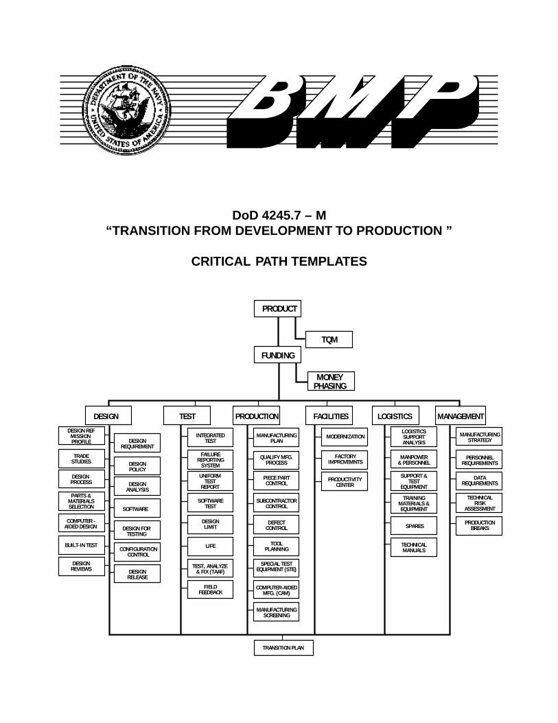
DoD 4245.7 – M“TRANSITION FROM DEVELOPMENT TO PRODUCTION ”
CRITICAL PATH TEMPLATES

i
1. EXECUTIVE SUMMARY
1.1 BACKGROUND ...............................................................................................11.2 BEST PRACTICES ..........................................................................................11.3 INFORMATION ................................................................................................2
2. INTRODUCTION
2.1 SCOPE .............................................................................................................32.2 SURVEY PROCESS ........................................................................................32.3 NAVY CENTERS OF EXCELLENCE ..............................................................32.4 COMPANY OVERVIEW ..................................................................................32.5 ACKNOWLEDGMENTS ..................................................................................32.6 COMPANY POINT OF CONTACT ..................................................................3
3. BEST PRACTICES
3.1 TOTAL QUALITY MANAGEMENTProcess Teams for Sheetmetal Parts....................................................5
3.2 DESIGNCOMPUTER-AIDED DESIGN
Worldwide Network and Shared-X ........................................................5
3.3 PRODUCTIONMANUFACTURING PLAN
Customer Support .................................................................................5PIECE PART CONTROL
Electric Arc Metal Spray Painting ..........................................................6Standard Parts: System II Electronics Cases........................................6Sheetmetal Work Order Management...................................................6Integration of Prototype Build with Production ......................................7
COMPUTER-AIDED MANUFACTURINGInteroperability of Tools, Tasks, and Computing Environment ..............8
C O N T E N T S
ii
C O N T E N T S (C o n t i n u e d)
3.4 FACILITIESFACTORY IMPROVEMENTS
Hazardous Waste Minimization Program ..............................................8Shop Safety Program ............................................................................9Machining and Finishing of Die Cast Parts .........................................10
PRODUCTIVITY CENTERJIT Manufacturing Cell ........................................................................10
3.5 LOGISTICSLOGISTICS SUPPORT ANALYSIS
Supplier Certification ...........................................................................10
3.6 MANAGEMENTMANUFACTURING STRATEGY
Corporate Values and the Hewlett-Packard Way ................................12Business Planning Process .................................................................12
PERSONNEL REQUIREMENTSInternal Communication ......................................................................13
DATA REQUIREMENTSTechnology, Quality, Responsiveness, Delivery, and Cost Report .....14Window Analysis .................................................................................14
4. INFORMATION
4.1 DESIGNPARTS AND MATERIAL SELECTION
Preliminary Cost Estimate ...................................................................15
4.2 PRODUCTIONPIECE PART CONTROL
Plastic Injection Molding ......................................................................15FACTORY IMPROVEMENTS
Aluminum Die Casting, Trimming, and Recycling ...............................15
4.3 MANAGEMENTPERSONNEL REQUIREMENTS
Leadership Development Survey ........................................................15Organizational Survey .........................................................................16

C O N T E N T S (C o n t i n u e d)
APPENDIX A - TABLE OF ACRONYMS ..........................................................................A-1APPENDIX B - BMP SURVEY TEAM ...............................................................................B-1APPENDIX C - NAVY CENTERS OF EXCELLENCE ......................................................C-1APPENDIX D - PREVIOUSLY COMPLETED SURVEYS .................................................D-1
iii
3-1 Module Cabinet Sizes ......................................................................................73-2 Hazardous Waste Generation ..........................................................................93-3 Hazardous Waste Reduction ...........................................................................93-4 Supplier Certification Process ........................................................................113-5 Window Analysis ............................................................................................14
F I G U R E S
S E C T I O N 1
EXECUTIVE SUMMARY
1
electronics cabinets in an effort to reduceproduction costs and create style consistency.
Sheetmetal Work Order Management Page 6PAFC’s fabrication shop uses an internally-developed software package to manage sheetmetalwork orders.
Integration of Prototype Buildwith Production Page 7HP has integrated prototype construction with itsproduction line that has led to a reduced prototypeturnaround time.
Interoperability of Tools,Tasks, and Computing Environment Page 7PAFC has developed the ability to download aproduct design and develop the fabrication process,process tooling, and NC programming throughCAD/CAM software.
Hazardous Waste Minimization Program Page 8PAFC developed a hazardous waste minimizationprogram as a result of the California HazardousSource Reduction and Management Act of 1989.
Shop Safety Program Page 8PAFC’s shop safety program exceeds the corporateand OSHA guidelines for environmental healthand safety.
Machining and Finishing of Die Cast Parts Page 8PAFC has established and refined a modifiedKanban cell for finish-machining front and reardie cast frames.
JIT Manufacturing Cell Page 9By instituting a JIT manufacturing cell for twoelectronic chassis assembly product lines, PAFChas detected production errors early in the process,and significantly reduced the chassis assemblytime.
Supplier Certification Page 9PAFC uses a supplier program based on internalbenchmarking.
1.1 BACKGROUND
The Best Manufacturing Practices (BMP) team con-ducted a survey at Hewlett-Packard (HP) Palo Alto Fabri-cation Center (PAFC), in Palo Alto, California. The pur-pose of the PAFC survey was to review and document itsbest practices and investigate any potential industry-wideproblems. The BMP program will use this documentationas an initial step in a voluntary technology sharing processamong the industry and government.
1.2 BEST PRACTICES
The best practices documented at HP PAFC are detailedin this report. These topics include:
Process Teams for Sheetmetal Parts Page 5A process team organization where individual payincreases are linked to the success of the overallshop rather than the performance of any oneindividual or team has proven very successful atPAFC.
Worldwide Network and Shared-X Page 5PAFC’s Worldwide Network and Shared-Xcapability connects almost all Hewlett-Packard(HP) worldwide facilities and provides a frameworkfor two or more network workstations to operate ina window as one for limited functions.
Customer Support Page 5HP provides design support for product designsproduced off-site by internal HP customers. PAFCCustomer Support and Site Engineering groupsare dedicated to continuously improving cost,performance, and quality.
Electric Arc Metal Spray Painting Page 6The PAFC Fabrication Shop has developed anelectric arc metal spray painting procedure toprovide an internal metal coating for electro-magnetic interference shielding, radio-frequencyinterference protection, or electrical grounding.
Standard Parts: System II Electronics Cases Page 6HP has established a standard for modular
Corporate Valuesand the Hewlett-Packard Way Page 9HP corporate values have become the basis fordefining corporate objectives which provide thebasis for the decision-making process at HP.
Business Planning Process Page 10Using the HP corporate objectives and values,PAFC has developed a five-step formal planningprocess.
Internal Communication Page 11HP PAFC uses a variety of methods to support itsefforts at communication with its employees. Thiseffort provides for enhanced two-waycommunication.
Technology, Quality,Responsiveness, Delivery, and Cost Report Page 12PAFC sends a monthly report to its customers thatindicates its performance in each of these criticalareas.
Window Analysis Page 12HP uses an analysis tool that helps identify thevariance between an actual process and desiredprocess and the means of optimizing the process.
1.3 INFORMATIONThe following information items are detailed in this report:
Preliminary Cost Estimate Page 15PAFC utilizes a cost estimating program to helpprepare cost estimates for its customers.
Plastic Injection Molding Page 15The problem of paint wearing off of letters andnumbers on keys was eliminated by PAFC’sdevelopment of two-color molding.
Aluminum Die Casting,Trimming and Recycling Page 15By standardizing processes and keeping lotquantities low, PAFC has been able to improve itsyield rate in aluminum die casting to nearly 100%.
Leadership Development Survey Page 15HP PAFC uses a leadership development surveyto assist in supervisor leadership development.
Organizational Survey Page 16Organizational survey at HP PAFC will beconducted every 15 months and will be used todetermine organizational strengths and target areasfor improvement.
2
S E C T I O N 2
INTRODUCTION
3
2.1 SCOPE
The purpose of the Best Manufacturing Practices (BMP)survey conducted at Hewlett-Packard (HP) Palo Alto Fab-rication Center (PAFC) was to identify best practices,review manufacturing problems, and document the results.The intent is to extend the use of progressive managementtechniques as well as high technology equipment and pro-cesses throughout industry and government facilities. Theultimate goal of the BMP program is to strengthen the U.S.industrial base and reduce the cost of defense systems bysolving manufacturing problems and improving quality andreliability.
A team of engineers accepted an invitation from Hewlett-Packard to review the processes and techniques used in itsfacilities located in Palo Alto, California. Potential indus-try-wide problems were also reviewed and documented.The review was conducted at PAFC on 22-26 June 1992 bythe team identified in Appendix B of this report.
The results of BMP surveys are entered into a database fordissemination through a central computer network. Theactual exchange of detailed data will be between companiesat their discretion.
The results of this survey should not be used to rate PAFCamong other companies. A company’s willingness to par-ticipate in the BMP program and the survey results have nobearing on one company’s performance over another’s. Thedocumentation in BMP reports is not intended to be allinclusive of the company’s best practices. Only selectednon-proprietary practices are reviewed and documented bythe BMP survey team.
2.2 SURVEY PROCESS
This survey was performed under the general surveyguidelines established by the Department of the Navy. Thesurvey concentrated on the functional areas of design, test,production, facilities, logistics, and management. The teamevaluated PAFC’s policies, practices, and strategies inthese areas. Furthermore, individual practices reviewedwere categorized as they relate to the critical path templatesof DoD 4245.7-M, “Transition from Development to Pro-duction.” PAFC identified potential best practices andindustry-wide problems. These practices and other areas ofinterest were discussed, reviewed, and documented fordistribution throughout the U.S. industrial base.
The format for this survey consisted of formal briefingsand discussions on best practices and problems. Time wasspent at PAFC reviewing practices, processes, and equip-ment. In-depth discussions were conducted to better under-stand and document the identified practices and problems.
2.3 NAVY CENTERS OF EXCELLENCE
Demonstrated industry-wide problems identified duringthe Best Manufacturing Practices surveys may be referredto one of the Navy Manufacturing Technology Centers ofExcellence. They are identified in Appendix C.
2.4 COMPANY OVERVIEW
The Palo Alto Fabrication Center (PAFC) is located inPalo Alto, California and is a division of Hewlett-Packard(HP). With 285 employees located in a 200,000 square-footfacility, PAFC supports five main fabrication technologies.In the sheetmetal area, PAFC furnishes products for elec-tronic instrumentation or test equipment. The plastic mold-ing area produces a low volume of 200 to 2,000 parts perorder for electronic instruments and test systems. A lowvolume production of 100 to 1,000 parts per order formature or standard product platforms and electronic instru-ments is supported by the aluminum die casting and ma-chining area. The cables area generates custom cables usedin HP systems applications and in medical products. Andthe computer cabinet assembly area produces cabinets forthe HP 1000 and HP 3000 systems.
The PAFC is one of several HP facilities that provides theseservices; consequently, it competes with these other inter-nal divisions as well as outside sources for HP business.
2.5 ACKNOWLEDGMENTS
Special thanks are due to all the people at Hewlett-Packard Palo Alto Fabrication Center whose participationmade this survey possible. In particular, the BMP programacknowledges the special efforts of Mr. David McLaughlinfor enabling this survey to occur.
2.6 COMPANY POINT OF CONTACT
While the information included in this report is intendedto be descriptive of the best practices and techniques ob-

4
served at PAFC, it is not intended to be all inclusive. It isanticipated that the reader will need more detailed data fortrue technology transfer.
The point of contact for this BMP survey is:
Mr. David McLaughlinProduction ManagerPalo Alto Fabrication CenterHewlett-Packard Company
395 Page Mill RoadPalo Alto, CA 94306Phone: (415) 857-6220FAX: (415) 857-5537
S E C T I O N 3
BEST PRACTICES
5
3.1 TOTAL QUALITY MANAGEMENT
Process Teams for Sheetmetal Parts
In early 1991, a process team organization was estab-lished in the sheetmetal area of the fabrication shop at PAFCto enhance the individual pay-for-performance system. Theprocess team organization was tasked to improve cross shiftteamwork, create an environment which supports totalquality control, and base individual reward on group suc-cess.
Four process teams were organized – flat parts (program-ming, punching, sanding, shearing); form parts (folding,drilling, stamping, welding, and various bench operations);riveting (inserting pins, nuts, labels); and painting/silkscreening. Team performance was rated in the areas ofproductivity (per cent of standard), quality (number of partsreturned), delivery (per cent of jobs on time), and rework(per cent of cost). Performance data was continuouslygathered by the shop floor control system, and team results,which had been calculated and posted monthly, were alsodone weekly.
Under the new system, individual pay increases arelinked to the success of the overall shop rather than theperformance of any one individual or team. This feature wasincluded in the system to ensure that teams would worktogether to achieve overall objectives. For example, indi-viduals could be moved between teams to satisfy short termneeds without concern about how it might affect their ownperformance ratings. The scoring system still encouragedcompetition between the teams.
After an initial three month adjustment period, a signifi-cant improvement in performance of all teams was achieved.In some cases, teams achieved a 30% improvement inoverall performance over the past year.
3.2 DESIGN
COMPUTER-AIDED DESIGN
Worldwide Network and Shared-X
PAFC’s Worldwide Network and Shared-X capabilityprovides customers and PAFC engineers the capability toprecisely discuss and resolve product concerns. The net-work connects almost all HP worldwide facilities, while the
Shared-X capability supplies the framework for two ormore network workstations to operate in a window as oneworkstation for limited functions.
Each HP facility has various distributed workstations andcomputer systems connected to THIN LAN hubs with thehubs connected to a THICK LAN backbone. Each facility’sbackbone is linked to a wide area network which providescommunication channels between facilities. Shared-X runsunder X-WINDOWS which allows a window to be openedon a remote workstation. It also allows either of the work-stations to control the cursor and either workstation user totype information in the window. The same information isconsequently displayed on both workstations. For example,a typical Shared-X application would display an ortho-graphic raster view of a part in question in the window onboth workstations. The customer and PAFC discuss theproblem area concurrently on the telephone while both areviewing the part and moving the cursor to highlight theareas of discussion.
Although Shared-X is a new product and performanceimprovement measurements are not yet available, the capa-bility is expected to significantly reduce communicationbarriers between remote sites. This in turn will reduce pro-totyping build iterations and improve schedule performance.
3.3 PRODUCTION
MANUFACTURING PLAN
Customer Support
HP provides design support for product designs producedoff-site by internal HP customers. The PAFC group is onlyone of several organizations in HP capable of providing thisdesign support service, and these organizations compete forthe various internal customers.
PAFC Customer Support and Site Engineering groupsare dedicated to continuously improving cost, performance,and quality. The Center is achieving approximately 95%on-time prototype delivery to its customers, and that capac-ity is augmented through out-sourcing with certified suppli-ers. Customer interaction throughout the process is continu-ally emphasized with Design for Manufacturability (DFM)considered a crucial element. In addition to DFM, customersupport and site engineering provides preliminary costing,new part introduction, fabrication process development,
6
process tooling, and NC Programming. Enhanced computersystem and application interoperability has provided effi-cient process execution for many of the Center’s functions.Support and site engineering provides the bridge for thetransitioning of prototype developments into production.
PIECE PART CONTROL
Electric Arc Metal Spray Painting
The PAFC Fabrication Shop has developed an electricarc metal spray painting procedure to provide an internalmetal coating for electro-magnetic interference shielding,radio-frequency interference protection, or electrical ground-ing. This metal coating is required on many of the plasticcases such as computer cabinets that are produced by theFabrication Shop. The electric arc spray process providesperformance improvements over the previously used flamespraying system.
The metal attaches to the surface by a mechanical bond.Prior to metal spraying, molded plastic parts are masked andabrasive-blasted to provide a rough surface for better adhe-sion of the metal. In the paint spray booth, parts are loadedinto a rotary fixture which allows access to the part andrequired masking. The gun is fed current carrying wire fromtwo coils. The arcing between the two wires vaporizes themetal. Due to the heat of the metal as it is applied, theoperator exercises caution to avoid damaging the part. Thespray gun is continuously moved at a range of almost sixinches to eight inches from the part. A curtain of oil cyclesbehind the work area to trap overspray. Because of thehazardous nature of the metal vapor generated by theprocess, the operator wears a protective helmet into whichoutside air is pumped.
This simple yet highly effective system provides greaterbonding strength than many alternative methods, and thefirm bonding of metal particles to each other preventschipping. In addition, a wide variety of metals such as zinc,copper, and brass can be applied.
Standard Parts: System II Electronics Cases
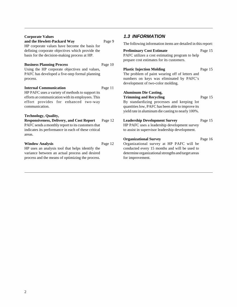
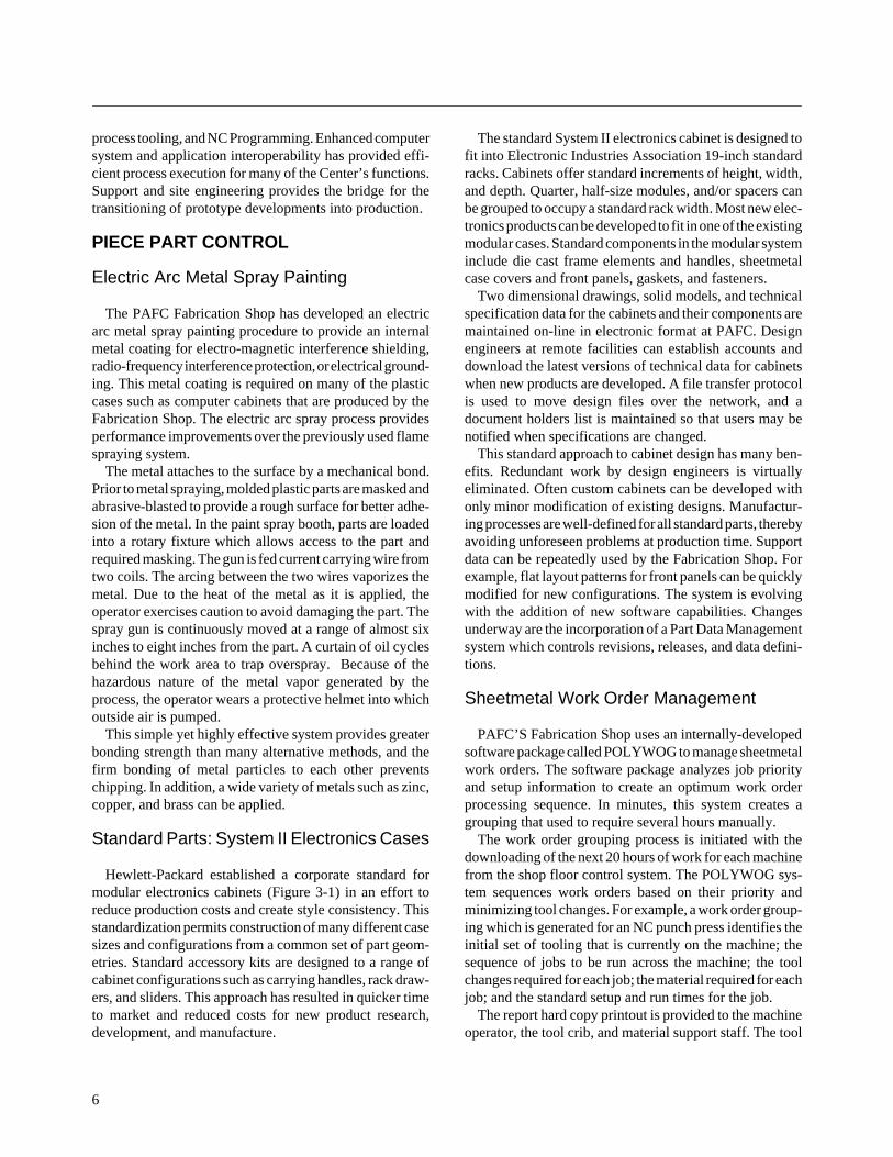
Hewlett-Packard established a corporate standard formodular electronics cabinets (Figure 3-1) in an effort toreduce production costs and create style consistency. Thisstandardization permits construction of many different casesizes and configurations from a common set of part geom-etries. Standard accessory kits are designed to a range ofcabinet configurations such as carrying handles, rack draw-ers, and sliders. This approach has resulted in quicker timeto market and reduced costs for new product research,development, and manufacture.
The standard System II electronics cabinet is designed tofit into Electronic Industries Association 19-inch standardracks. Cabinets offer standard increments of height, width,and depth. Quarter, half-size modules, and/or spacers canbe grouped to occupy a standard rack width. Most new elec-tronics products can be developed to fit in one of the existingmodular cases. Standard components in the modular systeminclude die cast frame elements and handles, sheetmetalcase covers and front panels, gaskets, and fasteners.
Two dimensional drawings, solid models, and technicalspecification data for the cabinets and their components aremaintained on-line in electronic format at PAFC. Designengineers at remote facilities can establish accounts anddownload the latest versions of technical data for cabinetswhen new products are developed. A file transfer protocolis used to move design files over the network, and adocument holders list is maintained so that users may benotified when specifications are changed.
This standard approach to cabinet design has many ben-efits. Redundant work by design engineers is virtuallyeliminated. Often custom cabinets can be developed withonly minor modification of existing designs. Manufactur-ing processes are well-defined for all standard parts, therebyavoiding unforeseen problems at production time. Supportdata can be repeatedly used by the Fabrication Shop. Forexample, flat layout patterns for front panels can be quicklymodified for new configurations. The system is evolvingwith the addition of new software capabilities. Changesunderway are the incorporation of a Part Data Managementsystem which controls revisions, releases, and data defini-tions.
Sheetmetal Work Order Management
PAFC’S Fabrication Shop uses an internally-developedsoftware package called POLYWOG to manage sheetmetalwork orders. The software package analyzes job priorityand setup information to create an optimum work orderprocessing sequence. In minutes, this system creates agrouping that used to require several hours manually.
The work order grouping process is initiated with thedownloading of the next 20 hours of work for each machinefrom the shop floor control system. The POLYWOG sys-tem sequences work orders based on their priority andminimizing tool changes. For example, a work order group-ing which is generated for an NC punch press identifies theinitial set of tooling that is currently on the machine; thesequence of jobs to be run across the machine; the toolchanges required for each job; the material required for eachjob; and the standard setup and run times for the job.
The report hard copy printout is provided to the machineoperator, the tool crib, and material support staff. The tool
7
FIGURE 3-1. MODULAR CABINET SIZES
crib ensures that the next several hours of punches are presetand ready for loading at the machine. Material support staffpull sheet stock and stack it in the order it will be used at themachine. Most of the sheet stock used by the shop ispurchased from the vendor in a standard 48-inch by 48-inchconfiguration. This standardization further minimizes setupchanges which are required between jobs. A copy of thework order grouping information is attached to each job setof sheet stock in the stack.
Other features of the system include networked computerterminals at each machine tool. The terminals are used bymachine operators to update the status of individual jobs.The system also permits the automatic resequencing of anyjobs which are not currently in process at any time. Thesheetmetal work order management system has signifi-cantly improved the flow of work through the sheetmetal
shop and reduced the time required for tool changes on theNC machines.
Integration of Prototype Build withProduction
Hewlett-Packard integrated prototype construction withits production line at the PAFC that has led to a reducedprototype turnaround time. Prior to integration, HP used thetraditional model shop method of building prototypes.Model makers received a prototype drawing and – usingtheir skill and ingenuity – developed the prototype. Thisapproach required the dedication of equipment, facilities,and personnel solely for prototype development (a func-tional unit), while not always yielding an economicallyproducible item in a production environment.
425.5 mm (16.75")
EIA/IEC HT 88.1 mm (3.469") Panel Area 3552cm (55in2)
425.5 mm (16.75")
EIA/IEC HT 88.1 mm (5.219") Panel Area 5422cm (84in2)
345.4 mm (13.60")
SIZE 88.1 FM Volume 9 750 cm 2 (595 in 3)
345.4 mm (13.60")
SIZE 132.6 FM Volume 15 322 cm 2 (935 in 3)
425.5 mm (16.75")
EIA/IEC HT 88.1 mm (5.219") Panel Area 5422cm (842in)
269.2 mm (10.60")
SIZE 177.0 FM Volume 20 893 cm 2 (1275in 3)
421.6 mm (16.60")
SIZE 88.1 FM Volume 12 1752 cm(775 in 3)
421.6 497.6 SIDE
497.8 mm (19.60")
SIZE 88.1 FM Volume 14 584 cm 2 (890 in 3 )
574.0 mm (22.60")
SIZE 88.1 FM Volume 17 042 cm 2 (1040 in3 )
VIEWS 574.6
421.6 mm (16.60")
SIZE 132.6 FM Volume 19 173 cm 2 (1170 in 3)
345.4FRONT VIEW
497.8 mm (19.60")
SIZE 132.6 FM Volume 14 584 cm 2 (890in 3)
574.0 mm (22.60")
SIZE 132.6 FM Volume 26 711 cm 3 (1630in 3)
421.6 mm (16.60")
SIZE 221.5 FM Volume 26 137 cm 3 (1595 in 3)
497.8 mm (19.60")
SIZE 177.0 FM Volume 31 299 cm 2 (1910in 3)
425.5 mm (16.75")
EIA/IEC HT 88.1 mm (5.219") Panel Area 5422cm (842in)
425.5 mm (16.75")
EIA/IEC HT 88.1 mm (5.219") Panel Area 5422cm (842in)
574.0 mm (22.60")
SIZE 177.0 FM Volume 36 461 cm 3 (2225in 3)
345.4 mm (13.60")
SIZE 221.5 FM Volume 26 547 cm 2 (1620in 3)
269.2 mm (10.60")
SIZE 221.5 FM Volume 33 102 cm 2 (2020in 3)
497.8 mm (19.60")
SIZE 221.5 FM Volume 39 575 cm 2 (2415in 3)
574.0 mm (22.60")
SIZE 221.5 FM Volume 46 129 cm 3 (2815 in 3)
345.4 mm (13.60")
SIZE 221.5 FM Volume 37 690 cm 3 (2300in 3)
425.5 mm (16.75")
SIZE 221.5 FM Volume 39 948 cm 2 (2440 in 3)
497.8 mm (19.60")
SIZE 265.9 FM Volume 26 547 cm 2 (16203in)
574.0 mm (22.60")
SIZE 265.9 FM Volume 55 798 cm 3 (3405 in 3)
425.5 mm (16.75")
EIA/IEC HT 88.1 mm (5.219") Panel Area 5422cm (842in)
425.5 mm (16.75")
SIZE 221.5 FM Volume 46 949 cm 2 (2865in 3)
425.5 mm (16.75")
SIZE 310.4 FM Volume 26 547 cm 2 (16203in)
497.8 mm (19.60")
SIZE 310.4 FM Volume 26 547 cm 2 (1620in 3)
574.0 mm (22.60")
SIZE 265.9 FM Volume 32 119 cm 2 (1960in 3)
8
PAFC decided to close the model shop, and prototypeconstruction was integrated with the production line. Theprototype request is now received at the Palo Alto facilityand reviewed by manufacturing engineering personnel.Producibility issues are identified and resolved, processplans developed, tooling manufactured, and the prototypemade using the same processes and equipment as theeventual production run – if initiated.
Prototypes are identified on the shop floor by highly vis-ible color coded cones. These colors also indicate the orderin which the prototypes are to be worked. When a machineoperator finishes an operation on an existing order, he checksthe incoming job rack for a prototype order and works on it.If one is there, it is the next job worked on. If one is notavailable, the next production job is set up and run. Usingthis system, prototypes receive priority at each operation.
Using this integrated system, PAFC is able to identify andaddress producibility issues prior to production build. Inaddition, piece part processes are developed and provenprior to production build. Tooling and NC programs are alsoproven out before production. Dual facilities and equip-ment are no longer required.
COMPUTER-AIDED MANUFACTURING
Interoperability of Tools, Tasks, andComputing Environment
PAFC continually strives for enhanced cost, performance,and quality for its internal customers. One means of achiev-ing this goal is the ability to download a product design anddevelop the fabrication process, process tooling, and NCprogramming through CAD/CAM software. The internalcustomer develops the product design and forwards a re-quest for a preliminary cost estimate and/or prototype build.This request is made by E-Mail to the Customer SupportEngineer (CE) at PAFC. The CE downloads the customer’sthree-dimensional sheetmetal body and/or two-dimensionalorthographic layout files in the local system. The CEdisplays and reviews the graphics information for com-pleteness and for DFM. Discrepancies and producibilityissues are addressed with the customer before continuingthe process.
Both the customer and PAFC CE use the ME-30 threedimensional and ME-10 two-dimensional (subset of ME-30)mechanical design application software packages. The soft-ware runs on HP-9000, 300 and 400 Series workstationsunder HP-UX (HP’s UNIX operating system). The work-stations are connected through a cadre of worldwide client/server networks. E-Mail appears in a window on the work-stations and graphic files are transferred using File TransferProtocol.
After the initial screening of the product design data andorder placement, the generation of data for the prototypebuild process begins. The ME-30 product graphic files aretranslated into IGES and then into Merry Mechanization’sSMP-81 application software. The SMP-81 package inte-grates the three-dimensional sheetmetal body unfoldinginto a flat pattern, the automatic dimensioning of the flatpattern, and the generating of NC data process steps. SMP-81FORM allows the CE to identify the surfaces to be unfolded.Part thickness, top surface, and features to be suppressed aredigitized while in FORM. SMP-81 Flat View then unfoldsthe three-dimensional sheetmetal body and dimensions theflat pattern. SMP-81 NC TAPE scans the flat pattern data-base and matches recognizable shapes to the Tool DataFiles/Database. The flat pattern and NC punch program aregraphically viewed by the NC Programmer. Modificationscan then be made to the NC punch coordinates by theprogrammer. When acceptable, the NC data file and toolingsetup files are generated. Upon request, the NC data andtooling information are downloaded to NC punch pressequipment.
Between 30% to 40% of the sheetmetal prototypes use theCAD/CAM three-dimensional sheetmetal body process.The impact of this process is a 10-times reduction in processdevelopment time over a process using paper designs.Although PAFC encourages its customers to develop thedesigns using three-dimension modeling, it also has a two-dimensional orthographic process using the ME-10 graph-ics software. Between 60% to 70% of the prototypes cur-rently use the two-dimensional process. Some paper isdeveloped between CAD and CAM in the two-dimensionalprocess.
3.4 FACILITIES
FACTORY IMPROVEMENTS
Hazardous Waste Minimization Program
As a result of the California Hazardous Source Reductionand Management Review Act of 1989, PAFC developed ahazardous waste minimization program to promote reduc-tion of hazardous waste at its source; encourage recyclingof waste that cannot be reduced at its source; and promotehandling practices that minimize environmental threats.The PAFC Fabrication Shop prepared two reports requiredby the Act – a Source Reduction Plan and a HazardousWaste Management Performance Report.
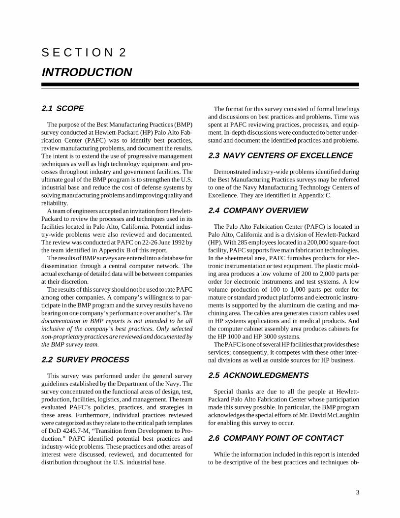
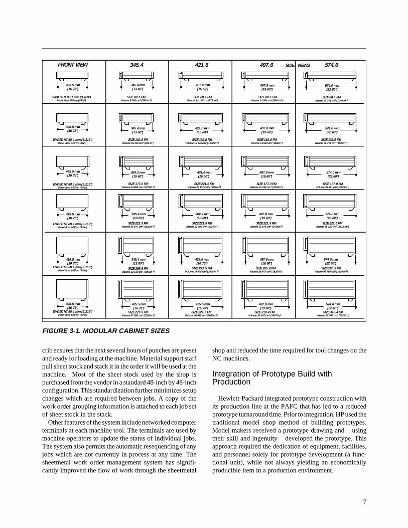
Hazardous wastes generated by the Fabrication Shopencompass waste water and oil, waste paint, aluminum andsteel dust, waste trichloroethane, zinc sludge, paint boothsludge, aluminum and mineral oil (Figure 3-2). (Water-
9
development of a chemical management program, elimina-tion of a Brite Dip etch process, changing of Brite Dip chemi-cals, recycling aluminum dust, and degreasers removal.
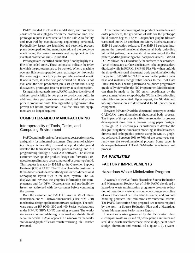
The Hazardous Waste Minimization Program has achieveda 69% reduction in quantity and 73% reduction in cost ofhazardous waste disposal from 1987 to 1991. The programis continuing to investigate new methods of reducing wasteand monitoring the introduction of new processes whichgenerate hazardous waste streams.
Shop Safety Program
PAFC has established a strong safety program whichexceeds both corporate and OSHA guidelines for environ-mental health and safety. Examples of aspects of the safetyprogram include additional safety guards on machine tools;elimination or minimization of many hazardous materials;daily operator safety checks on all machines; monthly pre-ventive maintenance checks on hoists; monthly self-inspec-tion of work areas by staff from the area and non-work areastaff; monthly staff safety meetings; standard safety formsto record action items; and cross-trained emergency responseteams. Standard safety issue forms identify the safety discrep-ancy, the priority of the safety item, ownership responsibil-ity, and the date that it was completed. This progressive safetyprogram is proactive and as a result, very few serious acci-dents have occurred at the PAFC facility.
FIGURE 3-3. HAZARDOUS WASTE REDUCTION
based paint sludge, which has its water removed by centri-fuge, is no longer considered hazardous waste.)
Hazardous waste source reductions at PAFC includechanges in raw materials, operational improvements,changes in production processes, and product reformulations(Figure 3-3). Hazardous waste reduction actions which havebeen taken as a result of the program include installation oflevel controls in spray paint booths, recycling of Trimsol andmachine oil, installation of sludge separators in paint booths,
FIGURE 3-2. HAZARDOUS WASTE GENERATION
��������������������������������������������������������������������������������������������������������������
�������������������������
����������������������������������������
���������������������������������������������
WASTE TRIMSOL 12.4% 775
MACHINE OIL 12.8% 800
WASTE OIL 52.8% 3300
TRI-CHRLOR 3.5% 220
WWT SLUDGE 3.5% 220
OTHER 6.2% 385
WASTE PAINT 8.8% 550
HAZARDOUS WASTE GENERATION
60000
40000
GALLONS
20000
01987 1988 1989 1990 1991 1992 1993 1994 1995
150
200
100
50
0
K DOLLARS
ACTUAL GALLONS
GOAL GALLONS COST
FY’87-FY’91 PERFORMANCE
69% REDUCTION IN QUANTITY 73% REDUCTION IN COST
HAZARDOUS WASTE REDUCTION
10
Machining and Finishing of Die Cast Parts
A modified Kanban cell was established at the PAFC forfinish-machining front and rear die cast frames. The cell hassignificantly reduced finished parts turnaround time, costs,and scrap and rework. Prior to creating this cell, personnelpulled basic die cast frames from stock on a lot basis, andindividual machines, jigs, and fixtures were set up for theparticular part being machined. The entire lot was then pro-cessed through machining and finishing. This approach ledto high inventory, WIP, and rework costs if defective cast-ings were found late in the processing cycle. The procedurewas followed for all parts produced from castings.
The modified Kanban cell includes sanding machinesand a specialized transfer machine capable of performingall required drilling and tapping on the different processedframe types. The transfer machine, designed and built byPAFC personnel, includes 15 stations. Pre-processing andpost-processing equipment has been moved into the imme-diate area, and the cell is self-contained with the exceptionof plating and painting.
Rearranging the operational sequence also allowed forearly detection of defective die castings before additionallabor costs were incurred, thereby reducing rework. Eachoperation was studied for work content and processingtime. When the pacing operation or constraint was found,that operation was improved to bring the line into balance.The cell is currently operated by seven personnel, and alldifferent frames can be processed through the same cell.
Final machined parts are degreased, cleaned, and imme-diately forwarded to the paint operation for final finishing.The painting, drying, and baking operation is conveyorizedat a controlled rate and allows finished parts to be packagedas they come off the paint line. Disposable corrugatedcardboard inserts are used on the painting trays to minimizerack clean-up and reduce hazardous material disposal.
PAFC has realized dramatic results by implementing thiscell. Changeover or setup time from one frame type toanother has been reduced from two or three hours to fiveminutes each. Productivity has increased from 22 parts perhour to 100 parts per hour, and rework costs have beengreatly reduced. A true pull system for manufacturing hasalso been developed.
PRODUCTIVITY CENTER
JIT Manufacturing Cell
HP PAFC developed and instituted a JIT manufacturingcell on two of its Electronic Chassis Assembly productlines. Knowing that customer needs for these assembliesvaried daily and that turnaround time was critical, HP
devised a method of satisfying these needs in the shortestpossible time. One chassis assembly contained 34 separateparts, the other 155 separate parts, and throughput in thefactory of any one component could require up to 30 days.Assembly time would add two or three days.
HP organized a JIT cell which guaranteed same-daydelivery of either of the assemblies. PAFC initially pro-duced a 28-30 day inventory of each of the individual pieceparts. These parts were stored in the final assembly area andthe assemblies were built as needed. A month-end inven-tory of the piece parts is now conducted and replenishmentorders are initiated for inventory replacement. Punchedblanks are delivered to the cell where final forming, rivet-ing, and gasketing operations are performed along with thefinal assembly. Off-line operations such as welding andscreening are coordinated by the cell operators.
The cell is operated by two people who are cross-trainedto perform any of the required operations. The cell operatorsdecide what needs to be done each day and who is going todo it. They maintain an inventory of anticipated dailydelivery requirements and keep the subassembly inventoryin balance.
Quality programs with the piece parts have been virtuallyeliminated as the cell operators are responsible for piecepart fabrication through final assembly. By carrying lowinventory, any production errors that may occur are caughtearly and do not affect delivery of final chassis assemblies.Delivery time of completed chassis assemblies has beenreduced to two hours.
3.5 LOGISTICS
LOGISTICS SUPPORT ANALYSIS
Supplier Certification
HP PAFC’s Business, Technology, Quality, Responsive-ness, Delivery and Cost (BTQRDC) program outlines theobjectives of the company’s supplier certification. The goalof this program is to help suppliers understand how HPprocurement personnel source, select, and monitor theperformance of fabricated parts used in its products. Suppli-ers are selected through a benchmarking process, and thoseselected suppliers commit to a program of continuousimprovement in product quality and reliability, improvedcustomer service, and an accelerated new product introduc-tion schedule. HP offers the preferred supplier the opportu-nity and techniques to develop and effectively manage itsarea based on experience gained through a working rela-tionship with Hewlett-Packard. HP also requires preferredsuppliers to complete an environmental questionnaire andcomply with EPA guidelines.
11
PAFC has baselined and benchmarked its own internalsheetmetal, plastic molding and die casting processes. Thebaseline is used to benchmark HP’s suppliers and eachsupplier is rated against the six BTQRDC categories. Cat-egories receiving high scores are investigated for bestpractices, and categories receiving low scores are identifiedfor improvements. The rating system uses weighted scoreswith a maximum obtainable score of 460 points.
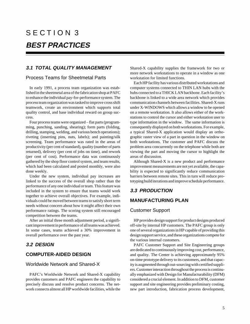
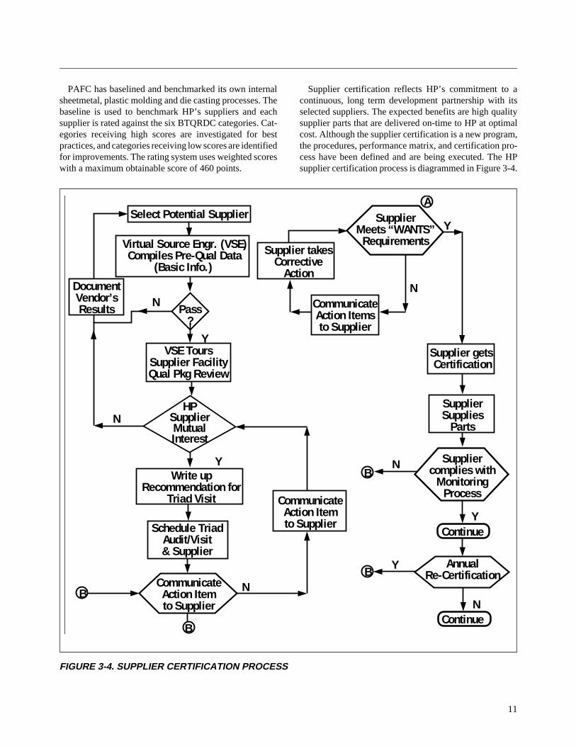
Supplier certification reflects HP’s commitment to acontinuous, long term development partnership with itsselected suppliers. The expected benefits are high qualitysupplier parts that are delivered on-time to HP at optimalcost. Although the supplier certification is a new program,the procedures, performance matrix, and certification pro-cess have been defined and are being executed. The HPsupplier certification process is diagrammed in Figure 3-4.
FIGURE 3-4. SUPPLIER CERTIFICATION PROCESS
Supplier Supplies
Parts
Supplier gets Certification
Supplier complies with
Monitoring Process
Annual Re-Certification
Continue
N
Y
Y
N
B
B
Communicate Action Item to Supplier
Communicate Action Item to Supplier
B
N
Y
N
N
Y
HP Supplier Mutual Interest
Schedule Triad Audit/Visit & Supplier
Write up Recommendation for
Triad Visit
B
VSE Tours Supplier Facility Qual Pkg Review
Pass ?
Document Vendor’s Results
Virtual Source Engr. (VSE) Compiles Pre-Qual Data
(Basic Info.)
Select Potential Supplier
Supplier takes Corrective
Action
Communicate Action Items to Supplier
Supplier Meets “WANTS”
Requirements
A
N
Y
SUPPLIER CERTIFICATION PROCESS
Continue
12
3.6 MANAGEMENT
MANUFACTURING STRATEGY
Corporate Valuesand the Hewlett-Packard Way
HP has developed and defined its own set of organiza-tional values and corporate objectives. These basic valuesand objectives have come to be known as the HP Way.These values serve as the basis for meeting corporateobjectives which are the foundation for the business deci-sion process at HP.
There are five underlying organizational values thatguide HP in working toward common objectives for thecorporation.
• Respect for individuals
• Focus on a high level of achievement and contributionin HP products and services, and in the performance ofits personnel
• An uncompromising commitment to integrity
• The achievement of common objectives through team-work
• The encouragement of flexibility and innovation
These values underlie the company’s common objectiveswhich focus on profit, customers, technical fields of inter-est, growth, employees, management, and citizenship. Corevalues define the company’s relationship to its customersand its employees. HP maintains that the central purpose ofits business is to satisfy real customer needs and that thoseneeds can be satisfied only with the active participation anddedication of everyone in the company. This drives thecompany’s commitment to quality and to its employees. HPplaces great value on the individual employee and focuseson providing employment security based on performance,recognition, and sharing in the company’s growth andprofitability. A key objective is profitability that is rein-vested in the company to provide self-financed growth.Fields of interest are chosen to build upon the company’stechnological strengths and the customer base to provide asteady flow of new products to existing markets as well asexpansion into new markets. Other objectives include em-phasis on individual initiative and creativity, and citizen-ship within the community.
These values and objectives are more than abstract ideasat HP. They are an integral part of the culture and businessprocesses and are clearly evident in daily activities. Theyhave built a sense of teamwork and commitment that en-ables the company to adapt successfully to the rapid changesit is experiencing in technology and the marketplace.
Business Planning Process
The planning process at PAFC is based on the HPcorporate objectives and values. Using these as a founda-tion, PAFC has developed a formal planning process toinject these principles into strategic business planning. InJanuary 1992, the management staff met to discuss changesfor the future and derive a set of values. They developed 12PAFC operating values, and these values serve as a set ofbeliefs to guide actions and provide a set of shared expec-tations for all facility personnel.
With the operating values as a framework, the manage-ment team developed two or three key objectives. Theseobjectives focus attention on the areas that PAFC needs toemphasize to be successful. Current key objectives areconcerned with quality, responsiveness, and management.An organizational alignment process is applied to ensurethat the organization is structured properly to best achievethe objectives. Department plans are developed and imple-mented. Progress is tracked by a formal quarterly reviewprocess both at the department and facility levels.
PAFC uses a five step process for developing businessstrategy. The process is applied separately in each of themajor technological areas in which the facility operates.These steps involve the following:
1. The process begins by making a determination of whothe customers are and what are their needs. Key cus-tomers are called “stakeholders.” The stakeholders areall internal HP organizations who are involved through-out the process and who participate actively in review-ing and defining the business strategy. As part ofdetermining the stakeholders and their needs, the pro-cess helps define what is strategic for the stakeholdersand provides them a competitive advantage.
2. The customer’s necessary products and services arethen determined by assessing current and future impactof the particular technology on the customer’s businessand which products or services within the technologyprovide key competitive advantages.
3. Similar businesses are benchmarked. The companiesto benchmark are often determined by the customer.Both internal and external suppliers are benchmarkedusing the customer’s key competitive advantage busi-ness factors. Needs identified through benchmarkingare mapped to existing business strategies.Benchmarking by PAFC is used as a tool to determineif the facility should continue to function as an internalsupplier for the technology, or if HP would be betterserved by an external supplier.
4. The fourth step is to understand the financial implica-tions. This involves an analysis of the cost advantages
13
to HP divisions of alternative business strategies, bar-riers of exit and entry, and investment needed to sup-port alternative strategies. A major difference herefrom previous planning methods is that the focus is onvalue added to HP rather than the objective of keepingwork in house and people employed at PAFC. Thiseffort is successful because of HP’s commitment to itspeople in providing alternative employment options iftheir jobs are threatened by elimination of a technologyor product line.
5. Step five is the analysis of potential problems such asthe risk of divestiture if it is determined that thebusiness area should be eliminated. This is a criticaldecision because once eliminated, the cost of re-entrywill usually be prohibitive.
At the completion of this process, recommendations aremade to the stakeholders by business area. Each recommen-dation is expressed in terms of a business value propositionthat defines value added minus the price of obtaining it. Aplan is provided for the required investment or the purchaseof products and services with specific objectives over a three-year period. A first year tactical plan is developed whichincludes a technology plan, resource plan, and if necessary,an outsourcing plan. If it is determined that an external sup-plier is the best source, PAFC will often provide best valueby serving as a virtual source by managing the purchase ofthe products or services from the external supplier.
The strategy and recommendations are reviewed by thestakeholders and the decision is made to implement or re-evaluate. The most unique aspect of this process is that thestrategy may require eliminating a business area for PAFC.Because of HP’s strong guiding objectives and values, thisprocess provides a strategy that is best for HP while protect-ing the employment of those involved. It supports the growthand profitability of the company and often provides newopportunities for growth and development for employees.
PERSONNEL REQUIREMENTS
Internal Communication
Effective internal communication is a key element atPAFC to ensure employees remain motivated and directlyinvolved in the company’s success. Successful communi-cation with all employees requires several efforts and ap-proaches to guarantee that both macro and micro views ofthe company are provided to employees in a timely andeffective manner. This communication must take the formof both broad overviews of company direction and wellbeing, and also show the individual employee’s role andimportance.
Hewlett-Packard uses several means to accomplish thisgoal including:
Twice yearly CEO addresses. Twice a year the CEOconducts a live broadcast to all HP employees presenting abusiness report on the company’s performance and an-nouncing the employee bonus. All employees are awardeda bonus as a percentage of their regular salary. This bonusis the same percentage for all employees from the CEO toproduction floor workers and is based on the semi-annualperformance of the company as communicated by the CEO.
Monthly pep rally. A monthly pep rally is held for all siteemployees and is hosted by the operations manager whoprovides all employees with an overview of the site’saccomplishments, problems and future direction. He fieldsquestions and provides recognition. Other information of ageneral interest is also disseminated.
Monthly forum. A monthly forum is used to provide acommon meeting ground of all site supervisors and manag-ers. This management team is strengthened because of theidea sharing and problem solving techniques fostered bythis gathering. These meetings help eliminate group bound-aries, promote teamwork, and improve morale.
Weekly work group. A weekly work group meeting isscheduled to discuss all material relevant to the individualwork group.
Newsletter. A bi-monthly newsletter is published to dis-seminate administrative information to all employees.
Bulletin boards. Bulletin boards are centrally located toprovide information on company current events, recogni-tion, new policies and guidelines, available training pro-grams, and local community job opportunities.
Organizational survey. An organizational survey is con-ducted to facilitate two-way communication.
Leadership survey. A leadership development survey isconducted to facilitate supervisor/employee communica-tion.
This HP approach has enabled the company to demon-strate adherence to its stated values of trust and respect forthe individual; focus on a high level of achievement andcontribution; and achieve common objectives through team-work by providing continuous two-way communicationthat provides employees with an assessment of the company’saccomplishments and future direction. It also enables theemployee to communicate his concerns and critique hissupervisor’s efforts.
DATA REQUIREMENTS
Technology, Quality, Responsiveness,Delivery, and Cost Report
PAFC initiated a formal monthly report to all its custom-ers to report on the facility’s monthly performance in theareas of technology, quality, responsiveness, delivery, andcost (TQRDC). PAFC originally received the TQRDCreport from its customers; as many as 30 of these reportswould be received monthly. As a result, considerable timewould be spent combining and using the information togenerate improvements. PAFC felt it could better serve itscustomers if it originated the report and supplied the infor-mation to the customer. This action allowed it to consolidateup to thirty reports into one, focus on problem areas,identify production goals and provide a valuable two-waycommunication tool to its customers.
The report provides narrative information on the site tech-nology, capabilities and cost structure, and metrics on qual-ity, responsiveness and on-time delivery. Results to dateinclude an improved customer relationship and a 30% im-provement in quality and timeliness over the past 12 months.
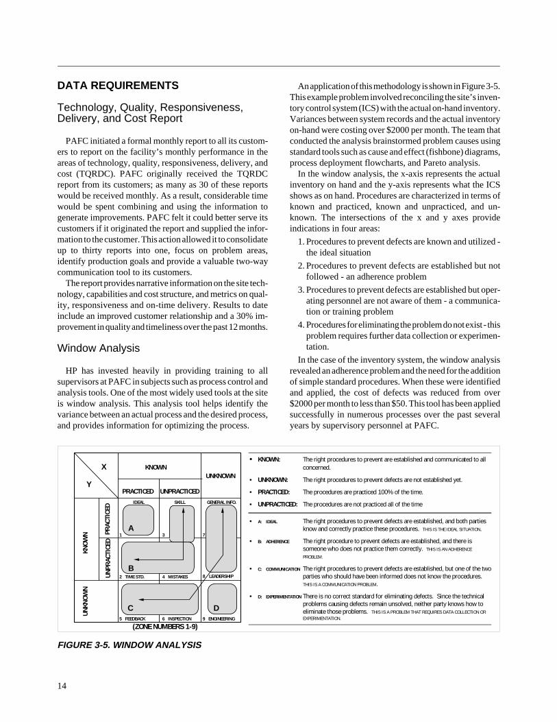
Window Analysis
HP has invested heavily in providing training to allsupervisors at PAFC in subjects such as process control andanalysis tools. One of the most widely used tools at the siteis window analysis. This analysis tool helps identify thevariance between an actual process and the desired process,and provides information for optimizing the process.
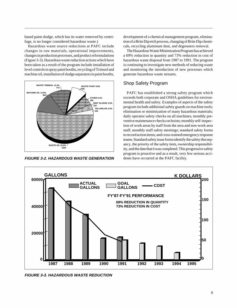
An application of this methodology is shown in Figure 3-5.This example problem involved reconciling the site’s inven-tory control system (ICS) with the actual on-hand inventory.Variances between system records and the actual inventoryon-hand were costing over $2000 per month. The team thatconducted the analysis brainstormed problem causes usingstandard tools such as cause and effect (fishbone) diagrams,process deployment flowcharts, and Pareto analysis.
In the window analysis, the x-axis represents the actualinventory on hand and the y-axis represents what the ICSshows as on hand. Procedures are characterized in terms ofknown and practiced, known and unpracticed, and un-known. The intersections of the x and y axes provideindications in four areas:
1. Procedures to prevent defects are known and utilized -the ideal situation
2. Procedures to prevent defects are established but notfollowed - an adherence problem
3. Procedures to prevent defects are established but oper-ating personnel are not aware of them - a communica-tion or training problem
4. Procedures for eliminating the problem do not exist - thisproblem requires further data collection or experimen-tation.
In the case of the inventory system, the window analysisrevealed an adherence problem and the need for the additionof simple standard procedures. When these were identifiedand applied, the cost of defects was reduced from over$2000 per month to less than $50. This tool has been appliedsuccessfully in numerous processes over the past severalyears by supervisory personnel at PAFC.
FIGURE 3-5. WINDOW ANALYSIS
14
• KNOWN: The right procedures to prevent are established and communicated to allconcerned.
• UNKNOWN: The right procedures to prevent defects are not established yet.
• PRACTICED: The procedures are practiced 100% of the time.
• UNPRACTICED: The procedures are not practiced all of the time
• A: IDEAL The right procedures to prevent defects are established, and both partiesknow and correctly practice these procedures. THIS IS THE IDEAL SITUATION.
• B: ADHERENCE The right procedure to prevent defects are established, and there issomeone who does not practice them correctly. THIS IS AN ADHERENCE
PROBLEM.
• C: COMMUNICATION The right procedures to prevent defects are established, but one of the twoparties who should have been informed does not know the procedures.THIS IS A COMMUNICATION PROBLEM.
• D: EXPERIMENTATION There is no correct standard for eliminating defects. Since the technicalproblems causing defects remain unsolved, neither party knows how toeliminate those problems. THIS IS A PROBLEM THAT REQUIRES DATA COLLECTION OREXPERIMENTATION.
Y
X KNOWN
PRACTICED UNPRACTICED
UNKNOWN
KNO
WN PR
ACTI
CED
UN
PRAC
TICE
D
UN
KNO
WN
A
B
C D
1 3
2 TIME STD. 4 MISTAKES
5 FEEDBACK 6 INSPECTION 9 ENGINEERING
8 LEADERSHIP
7
GENERAL INFO.SKILLIDEAL
(ZONE NUMBERS 1-9)
S E C T I O N 4
INFORMATION
15
FACTORY IMPROVEMENTS
Aluminum Die Casting, Trimming andRecycling
HP has standardized the design of its System II instru-ment cabinet line so only approximately 37 different basicdie castings are required. These basic parts are mainly in thefront frames, rear frames, handles, and struts. All these partsare cast at PAFC. Depending on the specification and enduse requirements, all parts are cast from either 360 alumi-num alloy or 443 aluminum alloy. Die casting of many otherparts is also accomplished at this facility.
Due to extensive process improvement efforts, PAFC hasbeen able to improve its yield rate from the 50% to 60%range to near 100%. A standard procedure keeps the last partrun on a given die with that die until the die is used again.By using this procedure and keeping lot quantities low,unseen defects are discovered early in the next piece partprocessing step and immediate corrective action can betaken such as dies reworked, machines checked for mal-functions, or material analysis performed.
With the recent addition of a spectrum analyzer, thePAFC is now able to recycle all of its own die cast wastematerial. Instead of selling this material as scrap and thenbuying virgin material ingots, it remelts the waste, addsmagnesium as required, and reuses the material. This hasresulted in a raw material cost reduction of approximately50%.
Standardization of basic casting designs, raw materialreclamation, standardized processes on the shop floor andmachine modernization have dramatically reduced costsand lead times for die casting at PAFC.
4.3 MANAGEMENT
PERSONNEL REQUIREMENTS
Leadership Development Survey
A leadership development survey at PAFC is being usedto assist in supervisor leadership development. This surveyconsists of over 60 questions designed to assist managers/supervisors in assessing their strengths and weaknesses bychanneling and improving the feedback they receive fromsubordinates.
4.1 DESIGN
PARTS AND MATERIAL SELECTION
Preliminary Cost Estimate
Cost estimates at PAFC are facilitated through the use ofa cost estimating program. Cost estimates, developed forseveral reasons, may include a request by the customer foran estimate on prototyping and follow-on fabrication costfor a particular design change. Estimates may also begenerated for budget purposes or for process improvementbaselines. Some cost drivers considered during the esti-mate are design complexity, fabrication process, partuniqueness, quantities required, material types and criticaltolerances.
The cost estimating software runs in a window on the HPworkstations. The program guides the CE through a seriesof questions and answers about the product and process.After the questions have been answered, the program calcu-lates product costs for various part quantities. “What if”calculations can easily be made by changing various costdrivers and rerunning the program. The customer can thenmake appropriate modifications based on the estimates.
During the estimating process, the PAFC CE may take theopportunity to suggest part feature changes that will resultin cost reductions and schedule improvements. The costestimating program can also be run by the customer whichfacilitates making decisions as early as possible in thedesign cycle.
4.2 PRODUCTION
PIECE PART CONTROL
Plastic Injection Molding
The PAFC has plastic injection molding capabilities withan added feature of two-color molding. With this addedfeature, the problem of paint wearing off of letters andnumbers on keys and switches has been eliminated. Theprocess involves molding the base part with the identifyingnomenclature (letters and numbers) raised and of one color.While the parts are still in the machine, a second overcoatof a contrasting color is molded onto the base part, leavingthe nomenclature exposed in its original color.
The survey is administered to all personnel workingunder the supervisor. After the survey has been processedand analyzed, the manager’s supervisor will use the resultsto help the manager set goals and target needed improve-ment in the areas of team building, leadership, coaching,and individual skill improvement. Follow-on surveys helpmeasure the manager’s corrective programs and their effec-tiveness. Additional benefits are anticipated because thissystem is expected to reinforce the concept that teamfeedback is important:
• values are stressed;• expectations are clarified;• shortcomings are exposed and addressed early;• successful practices are identified and reinforced; and• minimal time is spent on low value-added activities.
Organizational Survey
PAFC has just completed the administration of its firstorganizational health survey with the participation of all siteemployees. An organizational survey is used to determineorganizational strengths and target areas for improvement.The questions assessed organizational strengths and weak-nesses in the areas of management and supervision, com-munication, relationships, work environment, performance,development, and contribution and reorganization. Afterthe survey, indicated areas of need for improvement will bethe subject of process action team involvement. It is antici-pated that this process will be repeated at approximately 15-month intervals to promote continuous improvement in allapplicable areas.
16
A-1
A P P E N D I X A
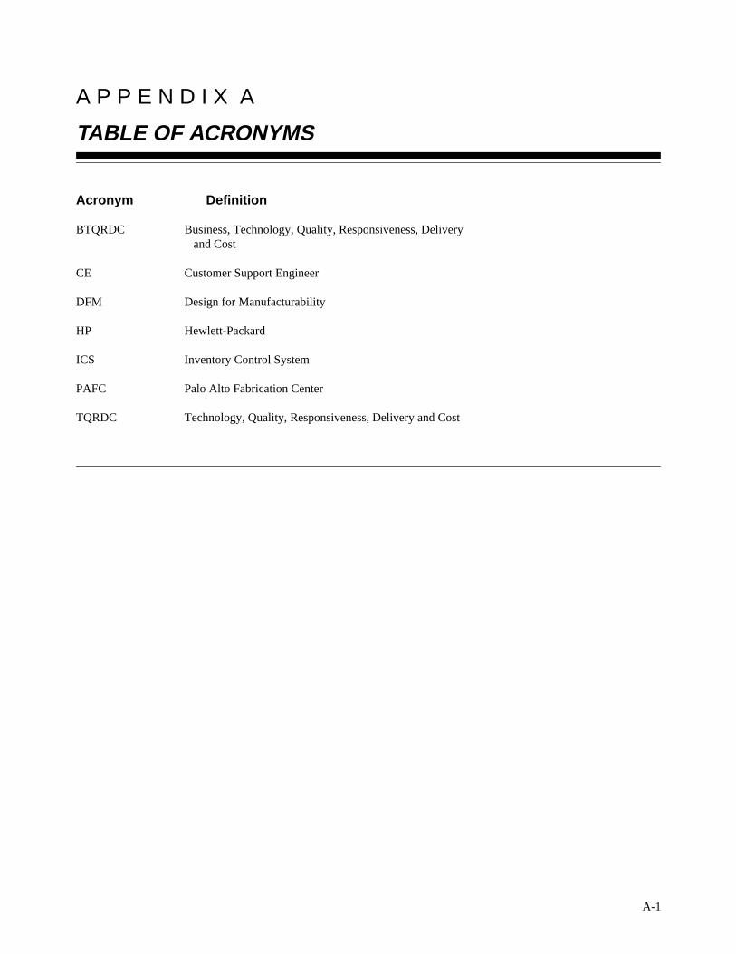
TABLE OF ACRONYMS
Acronym Definition
BTQRDC Business, Technology, Quality, Responsiveness, Delivery and Cost
CE Customer Support Engineer
DFM Design for Manufacturability
HP Hewlett-Packard
ICS Inventory Control System
PAFC Palo Alto Fabrication Center
TQRDC Technology, Quality, Responsiveness, Delivery and Cost
A P P E N D I X B
BMP SURVEY TEAM
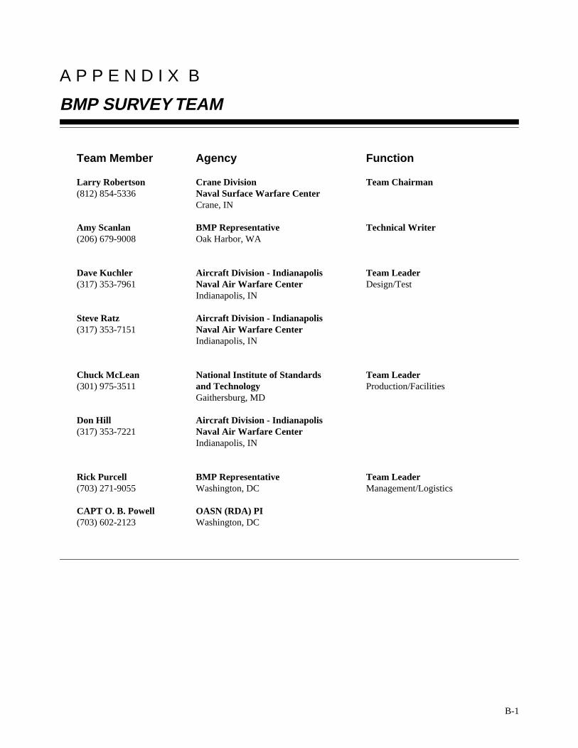
Team Member Agency Function
Larry Robertson Crane Division Team Chairman(812) 854-5336 Naval Surface Warfare Center
Crane, IN
Amy Scanlan BMP Representative Technical Writer(206) 679-9008 Oak Harbor, WA
Dave Kuchler Aircraft Division - Indianapolis Team Leader(317) 353-7961 Naval Air Warfare Center Design/Test
Indianapolis, IN
Steve Ratz Aircraft Division - Indianapolis(317) 353-7151 Naval Air Warfare Center
Indianapolis, IN
Chuck McLean National Institute of Standards Team Leader(301) 975-3511 and Technology Production/Facilities
Gaithersburg, MD
Don Hill Aircraft Division - Indianapolis(317) 353-7221 Naval Air Warfare Center
Indianapolis, IN
Rick Purcell BMP Representative Team Leader(703) 271-9055 Washington, DC Management/Logistics
CAPT O. B. Powell OASN (RDA) PI(703) 602-2123 Washington, DC
B-1
C-1
A P P E N D I X C
NAVY CENTERS OF EXCELLENCE
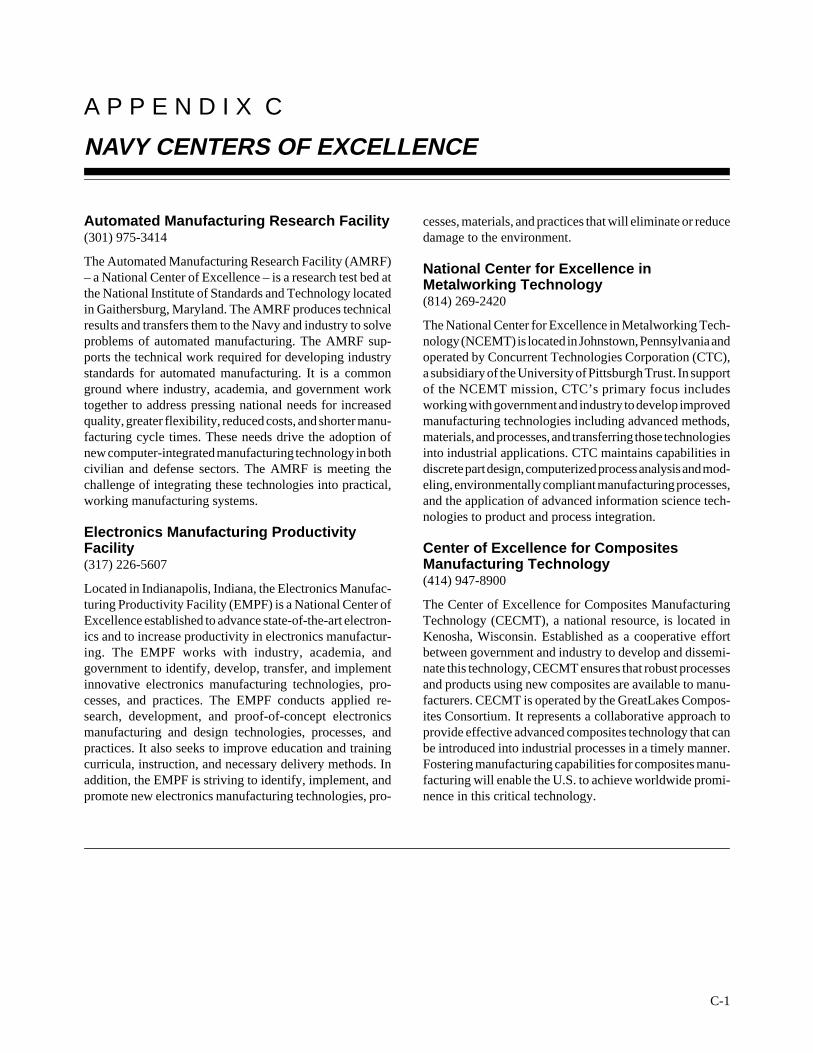
Automated Manufacturing Research Facility(301) 975-3414
The Automated Manufacturing Research Facility (AMRF)– a National Center of Excellence – is a research test bed atthe National Institute of Standards and Technology locatedin Gaithersburg, Maryland. The AMRF produces technicalresults and transfers them to the Navy and industry to solveproblems of automated manufacturing. The AMRF sup-ports the technical work required for developing industrystandards for automated manufacturing. It is a commonground where industry, academia, and government worktogether to address pressing national needs for increasedquality, greater flexibility, reduced costs, and shorter manu-facturing cycle times. These needs drive the adoption ofnew computer-integrated manufacturing technology in bothcivilian and defense sectors. The AMRF is meeting thechallenge of integrating these technologies into practical,working manufacturing systems.
Electronics Manufacturing ProductivityFacility(317) 226-5607
Located in Indianapolis, Indiana, the Electronics Manufac-turing Productivity Facility (EMPF) is a National Center ofExcellence established to advance state-of-the-art electron-ics and to increase productivity in electronics manufactur-ing. The EMPF works with industry, academia, andgovernment to identify, develop, transfer, and implementinnovative electronics manufacturing technologies, pro-cesses, and practices. The EMPF conducts applied re-search, development, and proof-of-concept electronicsmanufacturing and design technologies, processes, andpractices. It also seeks to improve education and trainingcurricula, instruction, and necessary delivery methods. Inaddition, the EMPF is striving to identify, implement, andpromote new electronics manufacturing technologies, pro-
cesses, materials, and practices that will eliminate or reducedamage to the environment.
National Center for Excellence inMetalworking Technology(814) 269-2420
The National Center for Excellence in Metalworking Tech-nology (NCEMT) is located in Johnstown, Pennsylvania andoperated by Concurrent Technologies Corporation (CTC),a subsidiary of the University of Pittsburgh Trust. In supportof the NCEMT mission, CTC’s primary focus includesworking with government and industry to develop improvedmanufacturing technologies including advanced methods,materials, and processes, and transferring those technologiesinto industrial applications. CTC maintains capabilities indiscrete part design, computerized process analysis and mod-eling, environmentally compliant manufacturing processes,and the application of advanced information science tech-nologies to product and process integration.
Center of Excellence for CompositesManufacturing Technology(414) 947-8900
The Center of Excellence for Composites ManufacturingTechnology (CECMT), a national resource, is located inKenosha, Wisconsin. Established as a cooperative effortbetween government and industry to develop and dissemi-nate this technology, CECMT ensures that robust processesand products using new composites are available to manu-facturers. CECMT is operated by the GreatLakes Compos-ites Consortium. It represents a collaborative approach toprovide effective advanced composites technology that canbe introduced into industrial processes in a timely manner.Fostering manufacturing capabilities for composites manu-facturing will enable the U.S. to achieve worldwide promi-nence in this critical technology.
A P P E N D I X D
PREVIOUSLY COMPLETED SURVEYS
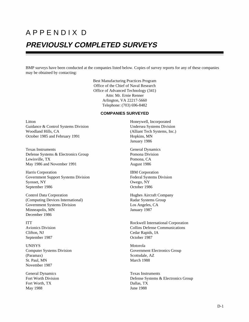
BMP surveys have been conducted at the companies listed below. Copies of survey reports for any of these companiesmay be obtained by contacting:
Best Manufacturing Practices ProgramOffice of the Chief of Naval ResearchOffice of Advanced Technology (341)
Attn: Mr. Ernie RennerArlington, VA 22217-5660Telephone: (703) 696-8482
COMPANIES SURVEYED
Litton Honeywell, IncorporatedGuidance & Control Systems Division Undersea Systems DivisionWoodland Hills, CA (Alliant Tech Systems, Inc.)October 1985 and February 1991 Hopkins, MN
January 1986
Texas Instruments General DynamicsDefense Systems & Electronics Group Pomona DivisionLewisville, TX Pomona, CAMay 1986 and November 1991 August 1986
Harris Corporation IBM CorporationGovernment Support Systems Division Federal Systems DivisionSyosset, NY Owego, NYSeptember 1986 October 1986
Control Data Corporation Hughes Aircraft Company(Computing Devices International) Radar Systems GroupGovernment Systems Division Los Angeles, CAMinneapolis, MN January 1987December 1986
ITT Rockwell International CorporationAvionics Division Collins Defense CommunicationsClifton, NJ Cedar Rapids, IASeptember 1987 October 1987
UNISYS MotorolaComputer Systems Division Government Electronics Group(Paramax) Scottsdale, AZSt. Paul, MN March 1988November 1987
General Dynamics Texas InstrumentsFort Worth Division Defense Systems & Electronics GroupFort Worth, TX Dallas, TXMay 1988 June 1988
D-1
24D-2
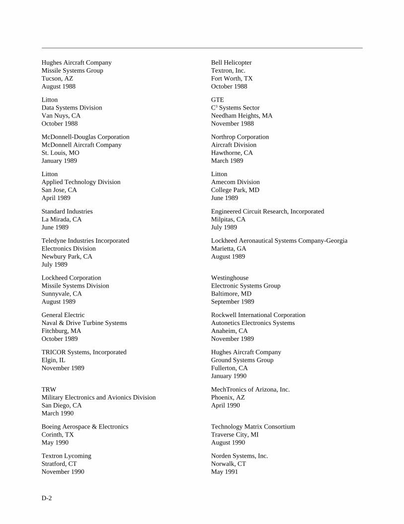
Hughes Aircraft Company Bell HelicopterMissile Systems Group Textron, Inc.Tucson, AZ Fort Worth, TXAugust 1988 October 1988
Litton GTEData Systems Division C3 Systems SectorVan Nuys, CA Needham Heights, MAOctober 1988 November 1988
McDonnell-Douglas Corporation Northrop CorporationMcDonnell Aircraft Company Aircraft DivisionSt. Louis, MO Hawthorne, CAJanuary 1989 March 1989
Litton LittonApplied Technology Division Amecom DivisionSan Jose, CA College Park, MDApril 1989 June 1989
Standard Industries Engineered Circuit Research, IncorporatedLa Mirada, CA Milpitas, CAJune 1989 July 1989
Teledyne Industries Incorporated Lockheed Aeronautical Systems Company-GeorgiaElectronics Division Marietta, GANewbury Park, CA August 1989July 1989
Lockheed Corporation WestinghouseMissile Systems Division Electronic Systems GroupSunnyvale, CA Baltimore, MDAugust 1989 September 1989
General Electric Rockwell International CorporationNaval & Drive Turbine Systems Autonetics Electronics SystemsFitchburg, MA Anaheim, CAOctober 1989 November 1989
TRICOR Systems, Incorporated Hughes Aircraft CompanyElgin, IL Ground Systems GroupNovember 1989 Fullerton, CA
January 1990
TRW MechTronics of Arizona, Inc.Military Electronics and Avionics Division Phoenix, AZSan Diego, CA April 1990March 1990
Boeing Aerospace & Electronics Technology Matrix ConsortiumCorinth, TX Traverse City, MIMay 1990 August 1990
Textron Lycoming Norden Systems, Inc.Stratford, CT Norwalk, CTNovember 1990 May 1991
25D-3
Naval Avionics Center United Electric ControlsIndianapolis, IN Watertown, MAJune 1991 June 1991
Kurt Manufacturing Co. MagneTek Defense SystemsMinneapolis, MN Anaheim, CAJuly 1991 August 1991
Raytheon Missile Systems Division AT&T Federal Systems Advanced TechnologiesAndover, MA and AT&T Bell LaboratoriesAugust 1991 Greensboro, NC and Whippany, NJ
September 1991
Tandem Computers Charleston Naval ShipyardCupertino, CA Charleston, SCJanuary 1992 April 1992
Conax Florida Corporation Texas InstrumentsSt. Petersburg, FL Semiconductor GroupMay 1992 Military Products
Midland, TXJune 1992
Information gathered from all BMP surveys is included in the Best Manufacturing Practices Network (BMPNET).Additionally, calendar of events and other relevant information are included on BMPNET. All inquiries regarding theBMPNET may be directed to:
BMP DirectorOffice of the Chief of Naval ResearchOffice of Advanced Technology (341)
800 North Quincy StreetArlington, VA 22217-5660Telephone: (703) 696-8482
FAX: 703) 696-8480