Best Management Practice 4.21 Sand...
28
Volume 2 (Technical Handbook) Georgia Stormwater Management Manual 3.24.21-1 4.21 Sand Filters Best Management Practice Description: Multi-chamber structure designed to treat stormwater runoff through filtration, using a sediment forebay, a sand bed as its primary filter media and, typically, an underdrain collection system. KEY CONSIDERATIONS DESIGN CRITERIA: Typically requires 2 to 6 feet of head Maximum contributing drainage area of 10 acres for surface sand filter; 2 acres for perimeter sand filter Sand filter media with underdrain system ADVANTAGES / BENEFITS: Applicable to small drainage areas Good for highly impervious areas Good retrofit capability DISADVANTAGES / LIMITATIONS: High maintenance burden Not recommended for areas with high sediment content in stormwater or clay/silt runoff areas Relatively costly Possible odor problems MAINTENANCE REQUIREMENTS: Inspect for clogging – rake first inch of sand Remove sediment from forebay/chamber Replace sand filter media as needed STORMWATER MANAGEMENT SUITABILITY Water Quality Channel Protection Overbank Flood Protection Extreme Flood Protection Accepts Hotspot Runoff: Yes (requires impermeable liner) in certain situations IMPLEMENTATION CONSIDERATIONS Land Requirement Capital Cost Maintenance Burden Residential Subdivision Use: No High Density/Ultra-Urban: Yes Drainage Area: 2-10 acres max. L H H
Transcript of Best Management Practice 4.21 Sand...

Volume 2 (Technical Handbook) Georgia Stormwater Management Manual 3.24.21-1
4.21 Sand Filters Best Management Practice
Description: Multi-chamber structure
designed to treat stormwater runoff through filtration, using a sediment forebay, a sand bed as its primary filter media and, typically, an underdrain collection system.
KEY CONSIDERATIONS
DESIGN CRITERIA:
Typically requires 2 to 6 feet of head
Maximum contributing drainage area of 10 acres for surface sand filter; 2 acres for perimeter sand filter
Sand filter media with underdrain system
ADVANTAGES / BENEFITS:
Applicable to small drainage areas
Good for highly impervious areas
Good retrofit capability
DISADVANTAGES / LIMITATIONS:
High maintenance burden
Not recommended for areas with high sediment content in stormwater or clay/silt runoff areas
Relatively costly
Possible odor problems
MAINTENANCE REQUIREMENTS:
Inspect for clogging – rake first inch of sand
Remove sediment from forebay/chamber
Replace sand filter media as needed
STORMWATER MANAGEMENT
SUITABILITY
Water Quality
Channel Protection
Overbank Flood Protection
Extreme Flood Protection
Accepts Hotspot Runoff: Yes
(requires impermeable liner)
in certain situations
IMPLEMENTATION
CONSIDERATIONS
Land Requirement
Capital Cost
Maintenance Burden
Residential Subdivision Use: No
High Density/Ultra-Urban: Yes
Drainage Area: 2-10 acres max.
L
H
H

3.24.21-2 Georgia Stormwater Management Manual Volume 2 (Technical Handbook)
POLLUTANT REMOVAL
Total Suspended Solids
Nutrients - Total Phosphorus / Total Nitrogen removal
Metals - Cadmium, Copper, Lead, and Zinc removal
Pathogens - Coliform, Streptococci, E.Coli removal
Soils: No restrictions
Other Considerations:
Typically needs to be combined with other controls to provide water quantity control
L=Low M=Moderate H=High
Runoff Reduction Credit:
0% of the runoff reduction volume provided
3.2.44.21.1 General Description
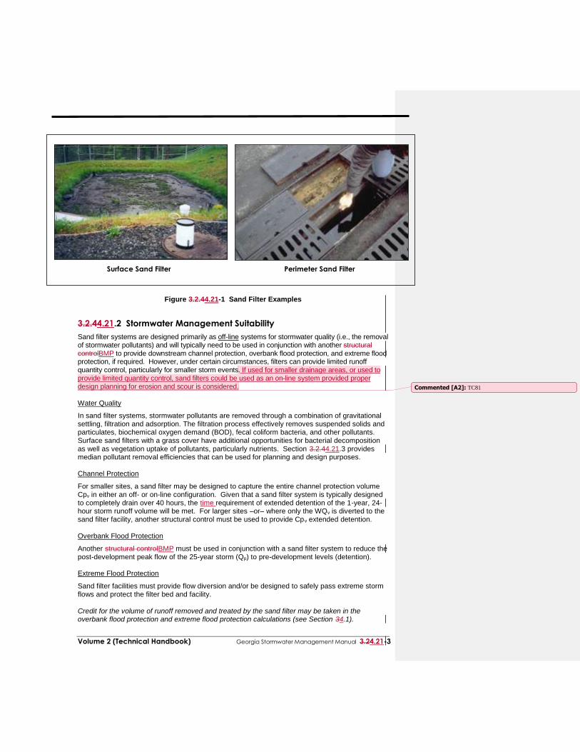
Sand filters (also referred to as filtration basins) are structural stormwater controlsBMPs that capture and temporarily store stormwater runoff and pass it through a filter bed of sand. Most sand filter systems consist of two-chamber structures. The first chamber is a sediment forebay or sedimentation chamber, which removes floatables and heavy sediments. The second is the filtration chamber, which removes additional pollutants by filtering the runoff through a sand bed. The filtered runoff is typically collected and returned to the conveyance system, though it can also be partially or fully exfiltrated into the surrounding soil in areas with porous soils. Because they have few site constraints beside head requirements, sand filters can be used on development sites where the use of other structural controls may be precluded. However, sand filter systems can be relatively expensive to construct and installmaintain. There are two primary sand filter system designs, the surface sand filter and the perimeter sand filter. Below are descriptions of these filter systems:
Surface Sand Filter – The surface sand filter is a ground-level open air structure that
consists of a pretreatment sediment forebay and a filter bed chamber. This system can treat drainage areas up to 10 acres in size and is most commonly typically located off-line. Surface sand filters can be designed as an excavation with earthen embankments or as a concrete or block structure.
Perimeter Sand Filter – The perimeter sand filter is an enclosed filter system typically constructed just below grade in a vault along the edge of an impervious area such as a parking lot. The system consists of a sedimentation chamber and a sand bed filter. Runoff flows into the structure through a series of inlet grates located along the top of the control.
A third design variant, the underground sand filter, is intended primarily for extremely space limited and high density areas and is thus only considered where local communities allow and requires additional planning for access, maintenance, and incorporation with the stormwater management plana limited application structural control. See subsection 3.3.4 for more details.
80%
50%
40%
50/25%
Commented [A1]: TC81
Volume 2 (Technical Handbook) Georgia Stormwater Management Manual 3.24.21-3
Surface Sand Filter Perimeter Sand Filter
Figure 3.2.44.21-1 Sand Filter Examples
3.2.44.21.2 Stormwater Management Suitability
Sand filter systems are designed primarily as off-line systems for stormwater quality (i.e., the removal of stormwater pollutants) and will typically need to be used in conjunction with another structural controlBMP to provide downstream channel protection, overbank flood protection, and extreme flood protection, if required. However, under certain circumstances, filters can provide limited runoff quantity control, particularly for smaller storm events. If used for smaller drainage areas, or used to provide limited quantity control, sand filters could be used as an on-line system provided proper design planning for erosion and scour is considered. Water Quality
In sand filter systems, stormwater pollutants are removed through a combination of gravitational settling, filtration and adsorption. The filtration process effectively removes suspended solids and particulates, biochemical oxygen demand (BOD), fecal coliform bacteria, and other pollutants. Surface sand filters with a grass cover have additional opportunities for bacterial decomposition as well as vegetation uptake of pollutants, particularly nutrients. Section 3.2.44.21.3 provides median pollutant removal efficiencies that can be used for planning and design purposes. Channel Protection
For smaller sites, a sand filter may be designed to capture the entire channel protection volume Cpv in either an off- or on-line configuration. Given that a sand filter system is typically designed to completely drain over 40 hours, the time requirement of extended detention of the 1-year, 24-hour storm runoff volume will be met. For larger sites –or– where only the WQv is diverted to the sand filter facility, another structural control must be used to provide Cpv extended detention. Overbank Flood Protection
Another structural controlBMP must be used in conjunction with a sand filter system to reduce the post-development peak flow of the 25-year storm (Qp) to pre-development levels (detention). Extreme Flood Protection
Sand filter facilities must provide flow diversion and/or be designed to safely pass extreme storm flows and protect the filter bed and facility. Credit for the volume of runoff removed and treated by the sand filter may be taken in the overbank flood protection and extreme flood protection calculations (see Section 34.1).
Commented [A2]: TC81

3.24.21-4 Georgia Stormwater Management Manual Volume 2 (Technical Handbook)
3.2.44.21.3 Pollutant Removal Capabilities
Both the surface and perimeter sand filters are presumed to be able to remove 80% of the total suspended solids load in typical urban post-development runoff when sized, designed, constructed and maintained in accordance with the recommended specifications. Undersized or poorly designed sand filters can reduce TSS removal performance. The following design pollutant removal rates are conservative average pollutant reduction percentages for design purposes derived from sampling data, modeling and professional judgment. In a situation where a removal rate is not deemed sufficient, additional controls may be put in place at the given site in a series or “treatment train” approach.
Total Suspended Solids – 80%
Total Phosphorus – 50%
Total Nitrogen – 25%
Fecal Coliform – 40%
Heavy Metals – 50% For additional information and data on pollutant removal capabilities for sand filters, see the National Pollutant Removal Performance Database (2nd EditionVersion 3) available at www.cwp.org and the National Stormwater Best Management Practices (BMP) Database at www.bmpdatabase.org
3.2.44.21.4 Application and Site Feasibility Criteria
Sand filter systems are well suited for highly impervious areas where land available for structural controlsBMPs is limited. Sand filters should primarily be considered for new construction or retrofit opportunities for commercial, industrial, and institutional areas where the sediment load is relatively low, such as: parking lots, driveways, loading docks, gas stations, garages, airport runways/taxiways, and storage yards. Sand filters may also be feasible and appropriate in some multi-family or higher density residential developments. To avoid rapid clogging and failure of the filter media, the use of sand filters should be avoided in areas with less than 50% impervious cover, or high sediment yield sites with clay/silt soils. Special attention should also be given to the topsoil and sod layers, if being used (See figure 4.21-42). The following basic criteria should be evaluated to ensure the suitability of a sand filter facility for meeting stormwater management objectives on a site or development. General Feasibility
Suitable for Residential Subdivision Usage – NO
Suitable for High Density/Ultra Urban Areas – YES
Regional Stormwater Control – NO Physical Feasibility - Physical Constraints at Project Site
Drainage Area – 10 acres maximum for surface sand filter; 2 acres maximum for perimeter sand filter
Space Required – Function of available head at site
Site Slope – No more than 6% slope across filter location
Minimum Head – Elevation difference needed at a site from the inflow to the outflow: 5 feet for surface sand filters; 2 to 3 feet for perimeter sand filters
Minimum Depth to Water Table – For a surface sand filter with exfiltration (earthen structure), 2 feet are required between the bottom of the sand filter and the elevation of the seasonally high water table
Soils – No restrictions; Group “A” soils generally required to allow exfiltration (for surface sand filter earthen structure)
Commented [A3]: TC82

Volume 2 (Technical Handbook) Georgia Stormwater Management Manual 3.24.21-5
Figure 4.21-2 Typical Sand Filter Media Cross Sections (Source: GDOT Drainage Manual, 2014)
Other Constraints / Considerations
Aquifer Protection – Do not allow exfiltration of filtered hotspot runoff into groundwater
Landscaping - Check with your local review authority to see if the planning of a grass cover or turf over a
sand filter is allowed.
Do not plant trees or provide shade within 15 feet of filtering area or where leaf litter will collect and clog filtering area.
Do not locate plants to block maintenance access to the facility.
Sod areas with heavy flows that are not stabilized with erosion control mats.
Divert flows temporarily from seeded areas until stabilized.
Planting on any area requiring a filter fabric should include material selected with care to insure that no tap roots will penetrate the filter fabric.

3.24.21-6 Georgia Stormwater Management Manual Volume 2 (Technical Handbook)
3.2.44.21.5 Planning and Design Criteria
The following criteria are to be considered minimum standards for the design of a sand filter
facility. Consult with the local review authority to determine if there are any variations to these criteria or additional standards that must be followed. A. LOCATION AND SITING
Surface sand filters should have a contributing drainage area of 10 acres or less. The maximum drainage area for a perimeter sand filter is 2 acres.
Sand filter systems are generally applied to land uses with a high percentage of impervious
surfaces. Sites with less than 50% imperviousness or high clay/silt sediment loads must not use a sand filter without adequate pretreatment due to potential clogging and failure of the filter bed. Any disturbed areas within the sand filter facility drainage area should be identified and stabilized. Filtration controls should only be constructed after the construction site is stabilized.
Surface sand filters are generally used in an off-line configuration where the water quality volume (WQv) is diverted to the filter facility through the use of a flow diversion structure and flow splitter. Stormwater flows greater than the WQv are diverted to other controls or downstream using a diversion structure or flow splitter.
Perimeter sand filters are typically sited along the edge, or perimeter, of an impervious area
such as a parking lot. Sand filter systems are designed for intermittent flow and must be allowed to drain and
reaerate between rainfall events. They should not be used on sites with a continuous flow from groundwater, sump pumps, or other sources.
B. GENERAL DESIGN
Surface Sand Filter
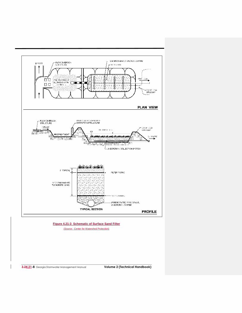
A surface sand filter facility consists of a two-chamber open-air structure, which is located at ground-level. The first chamber is the sediment forebay (a.k.a sedimentation chamber) while the second chamber houses the sand filter bed. Flow enters the sedimentation chamber where settling of larger sediment particles occurs. Runoff is then discharged from the sedimentation chamber through a perforated standpipe into the filtration chamber. After passing though the filter bed, stormwater runoff is collected by a perforated pipe and gravel underdrain system. Figure 3.2.44.21-6 3 provides plan view and profile schematics of a surface sand filter.
Perimeter Sand Filter
A perimeter sand filter facility is a vault structure located just below grade level. Runoff enters the device through inlet grates along the top of the structure into the sedimentation chamber. Runoff is discharged from the sedimentation chamber through a weir into the filtration chamber. After passing though the filter bed, runoff is collected by a perforated pipe and gravel underdrain system. Figure 3.2.44.21-7 4 provides plan view and profile schematics of a perimeter sand filter.
Underground Sand Filter
An underground sand filter is in an underground vault structure designed for high-density land use or ultra-urban applications where there is not enough space for a surface sand filter or other BMP. Due to its location below the surface, underground sand filters have a high maintenance burden and should only be used where adequate inspection and maintenance can be ensured. Figure 4.21-85 provides plan view and profile schematics of an underground sand filter.

Volume 2 (Technical Handbook) Georgia Stormwater Management Manual 3.24.21-7
C. PHYSICAL SPECIFICATIONS / GEOMETRY
Surface Sand Filter
The entire treatment system (including the sedimentation chamber) must temporarily hold at least 75% of the WQv prior to filtration. Figure 3.2.44.21-2 6 illustrates the distribution of the treatment volume (0.75 WQv) among the various components of the surface sand filter, including:
Vs – volume within the sedimentation basin
Vf – volume within the voids in the filter bed
Vf-temp – temporary volume stored above the filter bed
As – the surface area of the sedimentation basin
Af – surface area of the filter media
hs – height of water in the sedimentation basin
hf – average height of water above the filter media
df – depth of filter media
3.24.21-8 Georgia Stormwater Management Manual Volume 2 (Technical Handbook)
Figure 4.21-3 Schematic of Surface Sand Filter
(Source: Center for Watershed Protection)

Volume 2 (Technical Handbook) Georgia Stormwater Management Manual 3.24.21-9
Figure 4.21-4 Schematic of Perimeter Sand Filter
(Source: Center for Watershed Protection)

3.24.21-10 Georgia Stormwater Management Manual Volume 2 (Technical Handbook)
Figure 4.21-5 Schematic of Underground Sand Filter
(Source: Center for Watershed Protection) The sedimentation chamber must be sized to at least 25% of the computed WQv and have a
length-to-width ratio of at least 2:1. Inlet and outlet structures should be located at opposite ends of the chamber.
The filter area is sized based on the principles of Darcy’s Law. A coefficient of permeability
(k) of 3.5 ft/day for sand should be used. The filter bed is typically designed to completely drain in 40 hours or less.

Volume 2 (Technical Handbook) Georgia Stormwater Management Manual 3.24.21-11
Figure 3.2.44.21-2 Surface Sand Filter Volumes
Source: Claytor and SchuelerGDOT Drainage Manual, 19962014
The filter media consists of an 18-inch layer of clean washed medium sand (meeting ASTM
C-33 concrete sand or GADOT Fine Aggregate Size No. 10) on top of the underdrain system. Three inches of topsoil are placed over the sand bed. Permeable filter fabric is placed both above and below the sand bed to prevent clogging of the sand filter and the underdrain system. Figure 3.2.44.21-4 2 illustrates a typical media cross section.

3.24.21-12 Georgia Stormwater Management Manual Volume 2 (Technical Handbook)
Figure 4.21-6 Surface Sand Filter Volumes Source: GDOT Drainage Manual, 2014
The filter bed is typically equipped with a minimum 6-inch perforated PVC pipe (AASHTO M
252) underdrain in a gravel layer. The underdrain must have a minimum grade of 1/8-inch per foot (1% slope). Holes should be 3/8-inch diameter and spaced approximately 6 inches on center. Gravel should be clean washed aggregate with a maximum diameter of 3.5 inches and a minimum diameter of 1.5 inches with a void space of about 40% (GADOT No.3 Stone). Aggregate contaminated with soil shall not be used.
The structure of the surface sand filter may be constructed of impermeable media such as
concrete, or through the use of excavations and earthen embankments. When constructed with earthen walls/embankments, filter fabric should be used to line the bottom and side slopes of the structures before installation of the underdrain system and filter media.
Perimeter Sand Filter
The entire treatment system (including the sedimentation chamber) must temporarily hold at least 75% of the WQv prior to filtration. Figure 3.2.44.21-3 7 illustrates the distribution of the treatment volume (0.75 WQv) among the various components of the perimeter sand filter, including:
Vw – wet pool volume within the sedimentation basin
Vf – volume within the voids in the filter bed
Vtemp – temporary volume stored above the filter bed
As – the surface area of the sedimentation basin
Af – surface area of the filter media
hf – average height of water above the filter media (1/2 htemp)
df – depth of filter media

Volume 2 (Technical Handbook) Georgia Stormwater Management Manual 3.24.21-13
Figure 4.21-7 Perimeter Sand Filter Volumes
(Source: GDOT Drainage Manual, 2014)

3.24.21-14 Georgia Stormwater Management Manual Volume 2 (Technical Handbook)
The sedimentation chamber must be sized to at least 50% of the computed WQv. The filter area is sized based on the principles of Darcy’s Law. A coefficient of permeability
(k) of 3.5 ft/day for sand should be used. The filter bed is typically designed to completely drain in 40 hours or less.
The filter media should consist of a 12- to 18-inch layer of clean washed medium sand
(meeting ASTM C-33 concrete sand or GADOT Fine Aggregate Size No. 10) on top of the underdrain system. Figure 3.2.44.21-4 2 illustrates a typical media cross section.
The perimeter sand filter is typically equipped with a minimum 4 inch perforated PVC pipe
(AASHTO M 252) underdrain in a gravel layer. The underdrain must have a minimum grade of 1/8 inch per foot (1% slope). Holes should be 3/8-inch diameter and spaced approximately 6 inches on center. A permeable filter fabric should be placed between the gravel layer and the filter media. Gravel should be clean washed aggregate with a maximum diameter of 3.5 inches and a minimum diameter of 1.5 inches with a void space of about 40% (GADOT No.3 Stone). Aggregate contaminated with soil shall not be used.

Volume 2 (Technical Handbook) Georgia Stormwater Management Manual 3.24.21-15
Figure 3.2.44.21-3 Perimeter Sand Filter Volumes (Source: GDOT Drainage Manual, 2014Claytor and Schueler, 1996)
D. PRETREATMENT / INLETS
Pretreatment of runoff in a sand filter system is provided by the sedimentation chamber. Inlets to surface sand filters are to be provided with energy dissipators. Exit velocities from
the sedimentation chamber must be nonerosive. Figure 3.2.44.21-5 8 shows a typical inlet pipe from the sedimentation basin to the filter
media basin for the surface sand filter.
Figure 4.21-8 Surface Sand Filter Perforated Stand-Pipe
(Source: GDOT Drainage Manual, 2014) E. OUTLET STRUCTURES
Outlet pipe is to be provided from the underdrain system to the facility discharge. Due to the slow rate of filtration, outlet protection is generally unnecessary (except for emergency overflows and spillways).
F. EMERGENCY SPILLWAY
An emergency or bypass spillway must be included in the surface sand filter to safely pass flows that exceed the design storm flows. The spillway prevents filter water levels from overtopping the embankment and causing structural damage. The emergency spillway

3.24.21-16 Georgia Stormwater Management Manual Volume 2 (Technical Handbook)
should be located so that downstream buildings and structures will not be impacted by spillway discharges.
Figure 3.2.44.21-4 Typical Sand Filter Media Cross Sections
(Source: GDOT Drainage Manual, 2014Claytor and Schueler, 1996)
G. MAINTENANCE ACCESS
Adequate access must be provided for all sand filter systems for inspection and maintenance, including the appropriate equipment and vehicles. Access grates to the filter bed need to be included in a perimeter sand filter design. Facility designs must enable maintenance personnel to easily replace upper layers of the filter media.
H. SAFETY FEATURES
Surface sand filter facilities can be fenced to prevent access. Inlet and access grates to perimeter sand filters may be locked.
I. LANDSCAPING
Surface sand filters can be designed with a grass cover to aid in pollutant removal and prevent clogging. The grass should be capable of withstanding frequent periods of inundation and drought. The sand filter is covered with permeable topsoil and planted with

Volume 2 (Technical Handbook) Georgia Stormwater Management Manual 3.24.21-17
grass in a landscaped area. Properly planted, these facilities can be designed to blend into natural surroundings. Vegetated filter strips and buffers should fit into and blend with surrounding area. Native grasses are preferable, if compatible.
Figure 3.2.44.21-5 Surface Sand Filter Perforated Stand-Pipe (Source: GDOT Drainage Manual, 2014Claytor and Schueler, 1996)
J. ADDITIONAL SITE-SPECIFIC DESIGN CRITERIA AND ISSUES Physiographic Factors - Local terrain design constraints
Low Relief – Use of surface sand filter may be limited by low head
High Relief – Filter bed surface must be level
Karst – Use polyliner or impermeable membrane to seal bottom of earthen surface sand filter or use watertight structure
Soils
No restrictions Special Downstream Watershed Considerations
Trout Stream – Evaluate for stream warming; use shorter drain time (24 hours) or consider increasing media filter depth
Aquifer Protection – Use polyliner or impermeable membrane to seal bottom of earthen Commented [A4]: TC83

3.24.21-18 Georgia Stormwater Management Manual Volume 2 (Technical Handbook)
surface sand filter or use watertight structure; no exfiltration of filter runoff into groundwater

Volume 2 (Technical Handbook) Georgia Stormwater Management Manual 3.24.21-19
3.2.44.21.6 Design Procedures
Step 1. Compute runoff control volumes from the Unified Stormwater Sizing Criteria
Calculate the Water Quality Volume (WQv), Channel Protection Volume (Cpv), Overbank Flood Protection Volume (Qp), and the Extreme Flood Volume (Qf). Details on the Unified Stormwater Sizing Criteria are found in Section 1.42.2.
Step 2. Determine if the development site and conditions are appropriate for the use of a surface or perimeter sand filter.
Consider the Application and Site Feasibility Criteria in subsections 3.2.44.21.4 and 3.2.44.21.5-A (Location and Siting).
Step 3. Confirm local design criteria and applicability
Consider any special site-specific design conditions/criteria from subsection 3.2.44.21.5-J (Additional Site-Specific Design Criteria and Issues). Check with local officials and other agencies to determine if there are any additional restrictions and/or surface water or watershed requirements that may apply.
Step 4. Compute WQv peak discharge (Qwq)
The peak rate of discharge for water quality design storm is needed for sizing of off-line diversion structures (see subsection 23.1.7). (a) Using WQv, compute CN (b) Compute time of concentration using TR-55 method (c) Determine appropriate unit peak discharge from time of concentration (d) Compute Qwq from unit peak discharge, drainage area, and WQv.
Step 5. Size flow diversion structure, if needed
A flow regulator (or flow splitter diversion structure) should be supplied to divert the WQ v to the sand filter facility. Size low flow orifice, weir, or other device to pass Qwq.
Step 6. Size filtration basin chamber
The filter area is sized using the following equation (based on Darcy’s Law):
Af = (WQv) (df) / [(k) (hf + df) (tf)] where: Af = surface area of filter bed (ft2) df = filter bed depth (typically 18 inches, no more than 24 inches) k = coefficient of permeability of filter media (ft/day) (use 3.5 ft/day for sand) hf = average height of water above filter bed (ft)
(1/2 hmax, which varies based on site but hmax is typically 6 feet) tf = design filter bed drain time (days) (1.67 days or 40 hours is recommended maximum) Set preliminary dimensions of filtration basin chamber. See subsection 3.2.44.21.5-C (Physical Specifications/Geometry) for filter media specifications.

3.24.21-20 Georgia Stormwater Management Manual Volume 2 (Technical Handbook)
Step 7. Size sedimentation chamber
Surface sand filter: The sedimentation chamber should be sized to at least 25% of the
computed WQv and have a length-to-width ratio of 2:1. The Camp-Hazen equation is used to compute the required surface area: As = – (Qo/w) * Ln (1-E) Where: As = sedimentation basin surface area (ft2) Qo = rate of outflow = the WQv over a 24-hour period (ft3/s) w = particle settling velocity (ft/sec) E = trap efficiency Assuming:
90% sediment trap efficiency (0.9)
particle settling velocity (ft/sec) = 0.0033 ft/sec for imperviousness < 75%
particle settling velocity (ft/sec) = 0.0004 ft/sec for imperviousness < 75%
average of 24 hour holding period Then: As = (0.066) (WQv) ft2 for I < 75%
As = (0.0081) (WQv) ft2 for I 75% Set preliminary dimensions of sedimentation chamber. Perimeter sand filter: The sedimentation chamber should be sized to at least 50% of the
computed WQv. Use same approach as for surface sand filter.
Step 8. Compute Vmin
Vmin = 0.75 * WQv Step 9. Compute storage volumes within entire facility and sedimentation chamber orifice size
Surface sand filter: Vmin = 0.75 WQv = Vs + Vf + Vf-temp (1) Compute Vf = water volume within filter bed/gravel/pipe = Af * df * n Where: n = porosity = 0.4 for most applications
(2) Compute Vf-temp = temporary storage volume above the filter bed = 2 * hf * Af
(3) Compute Vs = volume within sediment chamber = Vmin - Vf - Vf-temp
(4) Compute hs = height in sedimentation chamber = Vs/As
(5) Ensure hs and hf fit available head and other dimensions still fit – change as necessary in design iterations until all site dimensions fit.
(6) Size orifice from sediment chamber to filter chamber to release Vs within 24-hours at average release rate with 0.5 hs as average head.
(7) Design outlet structure with perforations allowing for a safety factor of 10 (see example)
(8) Size distribution chamber to spread flow over filtration media – level spreader weir or

Volume 2 (Technical Handbook) Georgia Stormwater Management Manual 3.24.21-21
orifices. Perimeter sand filter: (1) Compute Vf = water volume within filter bed/gravel/pipe = Af * df * n
(2) Where: n = porosity = 0.4 for most applications
(3) Compute Vw = wet pool storage volume As * 2 feet minimum
(4) Compute Vtemp = temporary storage volume = Vmin – (Vf + Vw)
(5) Compute htemp = temporary storage height = Vtemp / (Af + As)
(6) Ensure htemp 2 * hf, otherwise decrease hf and re-compute. Ensure dimensions fit available head and area – change as necessary in design iterations until all site dimensions fit.
(7) Size distribution slots from sediment chamber to filter chamber. Step 10. Design inlets, pretreatment facilities, underdrain system, and outlet structures
See subsection 3.2.44.21-5-D through H for more details. Step 11. Compute overflow weir sizes
Surface sand filter: 1. Size overflow weir at elevation hs in sedimentation chamber (above perforated stand
pipe) to handle surcharge of flow through filter system from 25-year storm (see example).
2. Plan inlet protection for overflow from sedimentation chamber and size overflow weir at elevation hf in filtration chamber (above perforated stand pipe) to handle surcharge of flow through filter system from 25-year storm (see example).
Perimeter sand filter: Size overflow weir at end of sedimentation chamber to handle excess inflow, set at WQv elevation.

3.24.21-22 Georgia Stormwater Management Manual Volume 2 (Technical Handbook)
See Appendix D-3 for a Sand Filter Design Example

Volume 2 (Technical Handbook) Georgia Stormwater Management Manual 3.24.21-23
3.2.44.21.7 Inspection and Maintenance Requirements
Table 3.2.44.21-1. Typical Maintenance Activities for Sand Filters (Source: WMI, 1997; Pitt, 1997)
Activity
Schedule
Ensure that contributing area, facility, inlets and outlets are clear of debris.
Ensure that the contributing area is stabilized and mowed, with clippings removed.
Remove trash and debris.
Check to ensure that the filter surface is not clogging (also check after moderate and major storms).
Ensure that activities in the drainage area minimize oil/grease and sediment entry to the system.
If permanent water level is present (perimeter sand filter), ensure that the chamber does not leak, and normal pool level is retained.
Monthly
Check to see that the filter bed is clean of sediment, and the sediment chamber is not more than 50% full or 6 inches, whichever is less, of sediment. Remove sediment as necessary.
Make sure that there is no evidence of deterioration, spalling or cracking of concrete.
Inspect grates (perimeter sand filter).
Inspect inlets, outlets and overflow spillway to ensure good condition and no evidence of erosion.
Repair or replace any damaged structural parts.
Stabilize any eroded areas.
Ensure that flow is not bypassing the facility.
Ensure that no noticeable odors are detected outside the facility.
Annually
If filter bed is clogged or partially clogged, manual manipulation of the surface layer of sand may be required. Remove the top few inches of sand, roto-till or otherwise cultivate the surface, and replace media with sand meeting the design specifications.
Replace any filter fabric that has become clogged.
As needed
All best management practices require proper maintenance. Without proper maintenance, BMPs will not function as originally designed and may cease to function altogether. The design of all BMPs includes considerations for maintenance and maintenance access. For additional information on inspection and maintenance requirements, see Appendix XX. Additional Maintenance Considerations and Requirements
A record should be kept of the dewatering time for a sand filter to determine if maintenance is necessary.
When the filtering capacity of the sand filter facility diminishes substantially (i.e., when water
ponds on the surface of the filter bed for more than 48 hours), then the top layers of the filter media (topsoil and 2 to 3 inches of sand) will need to be removed and replaced. This will typically need to be done every 3 to 5 years for low sediment applications, more often for areas of high sediment yield or high oil and grease.
Removed sediment and media may usually be disposed of in a landfill. Regular inspection and maintenance is critical to the effective operation of sand filter facilities as designed. Maintenance responsibility for a sand filter system should be vested with a responsible authority by means of a legally binding and enforceable maintenance agreement that is executed

3.24.21-24 Georgia Stormwater Management Manual Volume 2 (Technical Handbook)
as a condition of plan approval.

Volume 2 (Technical Handbook) Georgia Stormwater Management Manual 3.24.21-25
3.2.44.21.8 Example Schematics
Figure 3.2.44.21-6 Schematic of Surface Sand Filter
(Source: Center for Watershed Protection)

3.24.21-26 Georgia Stormwater Management Manual Volume 2 (Technical Handbook)
Figure 3.2.44.21-7 Schematic of Perimeter Sand Filter
(Source: Center for Watershed Protection)

Volume 2 (Technical Handbook) Georgia Stormwater Management Manual 3.24.21-27
Figure 4.21-8 Schematic of Underground Sand Filter
(Source: Center for Watershed Protection)

3.24.21-28 Georgia Stormwater Management Manual Volume 2 (Technical Handbook)
3.2.4.9 Design Forms
Design Procedure Form: Sand Filters
PRELIMINARY HYDROLOGIC CALCULATIONS
1a. Compute WQv volume requirements
Compute Runoff Coefficient, Rv Rv =
Compute WQv WQv = acre-ft
1b. Compute Cpv Cpv = acre-ft
Compute average release rate release rate = cfs
Compute Qp-25 Qp-25 = acre-ft
Compute (as necessary) Qf Qf = acre-ft
SAND FILTER DESIGN
2. Is the use of a sand filter appropriate? Low Point in development area =
Low Point at stream invert =
Total available head =
Average depth, hf =
See subsections 3.2.2.4 and 3.2.2.5 - A
3. Confirm local design criteria and applicability. See subsection 3.2.2.5 - J
4. Compute WQv peak discharge (Qwq)
Compute Curve Number CN =
Compute Time of Concentration tc tc = hour
Compute Qwq Qwq = cfs
5. Size flow diversion structure
Low flow orifice - Orifice equation A = ft2
diam. = inch
Overflow weir - Weir equation Length = ft
6. Size filtration bed chamber
Compute area from Darcy's Law Af = ft2
Using length to width (2:1) ratio L = ft
W = ft
7. Size sedimentation chamber
Compute area from Camp-Hazen equation As = ft2
Given W from step 5, compute Length L = ft
8. Compute Vmin Vmin = ft3
9. Compute volume within practice
Surface sand filter
Volume within filter bed Vf = ft3
Temporary storage above filter bed Vf-temp = ft3
Sedimentation chamber (remaining volume) Vs = ft3
Height in sedimentation chamber hs = ft
Perforated stand pipe - Orifice equation A = ft2
diameter = in
Perimeter sand filter
Compute volume in filter bed Vf = ft3
Compute wet pool storage Vw = ft3
Compute temporary storage Vtemp = ft3
htemp = ft
10. Compute overflow weir sizes
Compute overflow - Orifice equation Q = cfs
Weir from sedimenation chamber- Weir equation Length = ft
Weir from filtration chamber- Weir equation Length = ft
Notes: