Bergen-Power Hardware Catalog 98H
43
BERGEN-POWER PIPE SUPPORTS INDEX Hardware Catalog 98H
-
Upload
process-pipe-support-systems-inc -
Category
Documents
-
view
317 -
download
6
description
Illustrates our hardware product line, incorporates some design changes andexpanded sizes in previous products along with additional concepts to meet current industry and code requirements.
Transcript of Bergen-Power Hardware Catalog 98H
BERGEN-POWER PIPE SUPPORTS
INDEX Hardware Catalog 98H

Foreword
Bergen-Power Pipe Supports is a complete line manufacturing and engineering organization offeringpipe hangers, supports, restraints and specialty devices to support and control piping and equipmentused in fossil power generating stations, petro-chemical plants, and other industrial processing pipingsystems.In addition to our product line, representing one of the most complete in the industry, Bergen-Powerprovides complete engineering and technical services, including analysis, hanger design and detailing,and other construction support programs. To provide effective distribution of our products and services,engineering and sales offices are maintained in major cities throughout the continental United States.This new catalog, illustrating our hardware product line, incorporates some design changes andexpanded sizes in previous products along with additional concepts to meet current industry andcode requirements.
General Notes
Outline dimensions and data shown in this catalog are for reference only and are not intended forinspection purposes.Designs and dimensions are subject to change without notice.All hanger products shown herein are manufactured in accordance with industry standards and are forinstallation and service as described. When used for other purposes or in ways other than those forwhich designed and manufactured, Bergen-Power cannot be held responsible for product failure,injuries, or property damage.Cataloged products meet requirements of MSS-SP-58 and MSS-SP-69.Maximum rated loads for hangers are based on a safety factor applicable to the codes listed in this cata-log or the allowable stresses specified in ASME B31.1, ASME B31.3, and MSS-SP-58.
INDEX BY FIGURE NUMBERFigure Page91..................................................19
91Z ...............................................20
93..................................................12
93L ...............................................12
94..................................................13
94SS .............................................13
100................................................21
100EL...........................................22
100SS ...........................................21
113A...............................................3
113B ...............................................3
123................................................12
123W............................................12
124................................................23
125................................................24
126................................................25
132................................................14
133................................................13
Figure Page133L .............................................13
134................................................26
137................................................27
160................................................11
165................................................14
175................................................28
175SP ...........................................28
194................................................29
220..................................................4
242A.............................................30
242B.............................................30
243A.............................................31
243B.............................................31
244A.............................................32
244B.............................................32
246................................................33
260..................................................5
276................................................15
Figure Page276P .............................................15
279................................................16
279L .............................................16
283................................................34
297..................................................6
298................................................35
304................................................36
304Z .............................................37
351-357Z ................................38-41
371................................................42
1020................................................7
1022................................................8
1302................................................5
1308................................................9
1309..............................................10
5105..............................................17
5308..............................................18
7054..............................................11
INCHES FAHRENHEIT POUNDS POUNDS
MILLIMETERS CELSIUS NEWTONS KILOGRAMS
DIMENSIONS TEMPERATURE LOADS WEIGHT
3
BERGEN-POWER PIPE SUPPORTS
CL
CL
E
S T
C
ROD SIZE A
E1
R
C
S T H
B
FIG 113A
FIG 113B
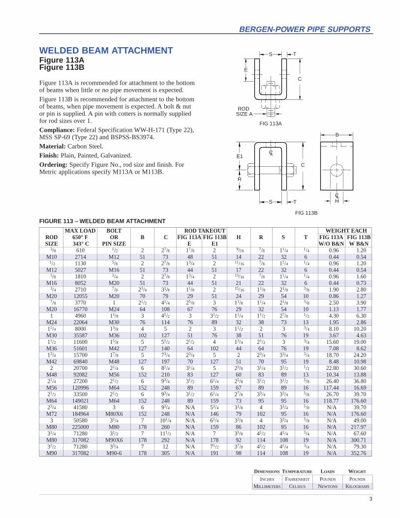
WELDED BEAM ATTACHMENTFigure 113AFigure 113B
Figure 113A is recommended for attachment to the bottomof beams when little or no pipe movement is expected.
Figure 113B is recommended for attachment to the bottomof beams, when pipe movement is expected. A bolt & nutor pin is supplied. A pin with cotters is normally suppliedfor rod sizes over 1.
Compliance: Federal Specification WW-H-171 (Type 22),MSS SP-69 (Type 22) and BSPSS-BS3974.
Material: Carbon Steel.
Finish: Plain, Painted, Galvanized.
Ordering: Specify Figure No., rod size and finish. ForMetric applications specify M113A or M113B.
MAX LOAD BOLT ROD TAKEOUT WEIGHT EACHROD 650° F OR B C FIG 113A FIG 113B H R S T FIG 113A FIG 113BSIZE 343° C PIN SIZE E E1 W/O B&N W B&N
3/8 610 1/2 2 27/8 17/8 2 9/16 7/8 11/4 1/4 0.96 1.20M10 2714 M12 51 73 48 51 14 22 32 6 0.44 0.54
1/2 1130 5/8 2 27/8 13/4 2 11/16 7/8 11/4 1/4 0.96 1.20M12 5027 M16 51 73 44 51 17 22 32 6 0.44 0.54
5/8 1810 3/4 2 27/8 13/4 2 13/16 7/8 11/4 1/4 0.96 1.60M16 8052 M20 51 73 44 51 21 22 32 6 0.44 0.73
3/4 2710 7/8 23/4 31/8 11/8 2 15/16 11/8 21/8 3/8 1.90 2.80M20 12055 M20 70 79 29 51 24 29 54 10 0.86 1.27
7/8 3770 1 21/2 41/4 25/8 3 11/8 11/4 21/8 3/8 2.50 3.90M20 16770 M24 64 108 67 76 29 32 54 10 1.13 1.77
1 4960 11/8 3 41/2 3 31/2 11/4 11/2 27/8 1/2 4.30 6.30M24 22064 M30 76 114 76 89 32 38 73 13 1.95 2.8611/4 8000 13/8 4 5 2 3 11/2 2 3 3/4 8.10 10.20M30 35587 M36 102 127 51 76 38 51 76 19 3.67 4.6311/2 11600 15/8 5 51/2 21/2 4 13/4 21/2 3 3/4 15.60 19.00M36 51601 M42 127 140 64 102 44 64 76 19 7.08 8.6213/4 15700 17/8 5 73/4 23/4 5 2 23/4 33/4 3/4 18.70 24.20M42 69840 M48 127 197 70 127 51 70 95 19 8.48 10.98
2 20700 21/4 6 81/4 31/4 5 23/8 31/4 31/2 1/2 22.80 30.60M48 92082 M56 152 210 83 127 60 83 89 13 10.34 13.8821/4 27200 21/2 6 93/4 31/2 61/4 25/8 31/2 31/2 5/8 26.40 36.80M56 120996 M64 152 248 89 159 67 89 89 16 117.44 16.6921/2 33500 21/2 6 93/4 31/2 61/4 27/8 33/4 33/4 5/8 26.70 39.70M64 149021 M64 152 248 89 159 73 95 95 16 118.77 176.6023/4 41580 3 6 93/4 N/A 53/4 31/8 4 33/4 5/8 N/A 39.70M72 184964 M80X6 152 248 N/A 146 79 102 95 16 N/A 176.60
3 50580 31/4 7 101/4 N/A 61/4 33/8 4 33/4 5/8 N/A 49.00M80 225000 M80 178 260 N/A 159 86 102 95 16 N/A 217.9731/4 71280 31/2 7 111/2 N/A 7 35/8 41/2 41/4 3/4 N/A 67.60M80 317082 M90X6 178 292 N/A 178 92 114 108 19 N/A 300.7131/2 71280 33/4 7 12 N/A 71/2 37/8 41/2 41/4 3/4 N/A 79.30M90 317082 M90-6 178 305 N/A 191 98 114 108 19 N/A 352.76
FIGURE 113 – WELDED BEAM ATTACHMENT
INCHES FAHRENHEIT POUNDS POUNDS
MILLIMETERS CELSIUS NEWTONS KILOGRAMS
DIMENSIONS TEMPERATURE LOADS WEIGHT
4
BERGEN-POWER PIPE SUPPORTS
F
E
D
H
C
C/2 G
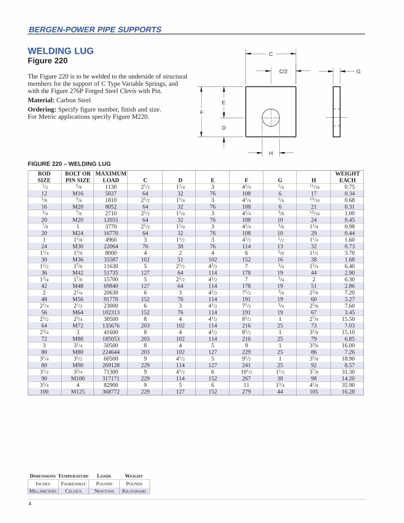
WELDING LUGFigure 220
The Figure 220 is to be welded to the underside of structuralmembers for the support of C Type Variable Springs, andwith the Figure 276P Forged Steel Clevis with Pin.
Material: Carbon Steel
Ordering: Specify figure number, finish and size.For Metric applications specify Figure M220.
FIGURE 220 – WELDING LUG
ROD BOLT OR MAXIMUM WEIGHTSIZE PIN SIZE LOAD C D E F G H EACH
1/2 5/8 1130 21/2 11/4 3 41/4 1/4 11/16 0.7512 M16 5027 64 32 76 108 6 17 0.345/8 3/4 1810 21/2 11/4 3 41/4 1/4 13/16 0.6816 M20 8052 64 32 76 108 6 21 0.313/4 7/8 2710 21/2 11/4 3 41/4 3/8 15/16 1.0020 M20 12055 64 32 76 108 10 24 0.457/8 1 3770 21/2 11/4 3 41/4 3/8 11/8 0.9820 M24 16770 64 32 76 108 10 29 0.441 11/8 4960 3 11/2 3 41/2 1/2 11/4 1.6024 M30 22064 76 38 76 114 13 32 0.7311/4 13/8 8000 4 2 4 6 5/8 11/2 3.7030 M36 35587 102 51 102 152 16 38 1.6811/2 15/8 11630 5 21/2 41/2 7 3/4 13/4 6.4036 M42 51735 127 64 114 178 19 44 2.9013/4 17/8 15700 5 21/2 41/2 7 3/4 2 6.3042 M48 69840 127 64 114 178 19 51 2.862 21/4 20630 6 3 41/2 71/2 3/4 23/8 7.2048 M56 91770 152 76 114 191 19 60 3.2721/4 21/2 23000 6 3 41/2 71/2 3/4 25/8 7.6056 M64 102313 152 76 114 191 19 67 3.4521/2 23/4 30500 8 4 41/2 81/2 1 27/8 15.5064 M72 135676 203 102 114 216 25 73 7.0323/4 3 41600 8 4 41/2 81/2 1 31/8 15.1072 M80 185053 203 102 114 216 25 79 6.853 31/4 50500 8 4 5 9 1 33/8 16.0080 M80 224644 203 102 127 229 25 86 7.2631/4 31/2 60500 9 41/2 5 91/2 1 35/8 18.9080 M90 269128 229 114 127 241 25 92 8.5731/2 33/4 71300 9 41/2 6 101/2 11/2 37/8 31.3090 M100 317171 229 114 152 267 38 98 14.2033/4 4 82900 9 5 6 11 13/4 41/8 35.90100 M125 368772 229 127 152 279 44 105 16.28

5
BERGEN-POWER PIPE SUPPORTS
D
B
B/2
B/2B
C
A (MAX.)
EXISTING
TYP.
WASHER PLATEFigure 260
This product to be welded to back to back channels orangles for supporting pipe with rods or U-Bolts.
Sufficient contact surface to the supporting structure mustbe made to develop maximum load capacity. Dimension“A” should not be exceeded.
Material: Carbon Steel.
Finish: Plain, Galvanized.
Ordering: Specify figure number, finish, and rod size. For Metric applications specify Figure M260.
FIGURE 260 – WASHER PLATE
ROD MAX HOLE WGTSIZE LOAD A B C D EACH
3/8 610 11/2 3 1/4 7/16 0.63M10 2713 38 76 6 11 0.29
1/2 1130 11/2 3 1/4 9/16 0.61M12 5026 38 76 6 14 0.28
5/8 1810 11/2 3 3/8 11/16 0.95M16 8051 38 76 10 17 0.43
3/4 2710 2 4 3/8 13/16 1.60M20 12055 51 102 10 21 0.73
7/8 3770 2 4 1/2 15/16 2.17M20 16770 51 102 13 24 0.98
1 4960 21/2 4 1/2 11/16 2.15M24 22063 64 102 13 27 0.9811/8 6230 21/2 4 1/2 11/4 2.13M30 27712 64 102 13 32 0.9711/4 8000 3 5 1/2 13/8 3.28M30 35586 76 127 13 35 1.4911/2 11630 31/2 5 5/8 15/8 4.05M36 51733 89 127 16 41 1.8413/4 15700 31/2 5 5/8 2 3.88M42 69837 89 127 16 51 1.76
2 20700 4 6 3/4 21/4 4.47M48 92078 102 152 19 57 2.0321/4 27200 4 6 3/4 21/2 6.62M56 120991 102 152 19 64 3.0021/2 33500 41/2 6 3/4 23/4 6.40M64 149015 114 152 19 70 2.9023/4 41580 41/2 6 3/4 3 6.16M72 184956 114 152 19 76 2.79
3 50580 41/2 6 3/4 31/4 5.89M80 224990 114 152 19 83 2.6731/4 60480 41/2 6 3/4 31/2 5.56M80 269027 114 152 19 89 2.5231/2 71280 5 7 3/4 33/4 8.07M90 317068 127 178 19 95 3.6633/4 82890 5 7 3/4 4 7.75M95 368711 127 178 19 102 3.52
TL C
L
SELF DRILLING ANCHORFigure 1302
The Figure 1302 is used for bolting components to concretestructures. The shell is fitted with a snap off chucking endfor power drilling and shell expansion.
NOTE: This product is not designed or recommended fordirect threading to hanger rods. Intermediate attachmentsare recommended.
WARNING: Recommended practice in sizing and application of concrete fasteners should be followed.
Material: Case hardened plated shell and expander plug.
Finish: Electro-Galvanized.
Ordering: Specify figure number and size. For Metricapplications specify Figure M1302.
FIGURE 1302 – SELF DRILLING ANCHOR
3500 PSICONCRETE
SAFE WORKINGTAP LOAD C L T L WGTSIZE TENSION SHEAR EACH
1/4 915 330 7/16 13/32 3/8 0.05M6 4070 1468 11 28 10 0.023/8 1415 840 9/16 117/32 9/16 0.10
M10 6294 3737 14 39 14 0.051/2 2125 1680 11/16 21/32 13/16 0.17
M12 9453 7473 17 52 21 0.085/8 2925 2975 27/32 215/32 15/16 0.32
M16 13012 13234 21 63 24 0.153/4 4050 4050 1 31/4 17/32 0.56
M20 18016 18016 25 83 31 0.257/8 4460 4610 11/8 311/32 113/32 0.72
M20 19840 20507 29 85 36 0.33
INCHES FAHRENHEIT POUNDS POUNDS
MILLIMETERS CELSIUS NEWTONS KILOGRAMS
DIMENSIONS TEMPERATURE LOADS WEIGHT
6
BERGEN-POWER PIPE SUPPORTS
BEAMFLANGEWIDTH
A
E
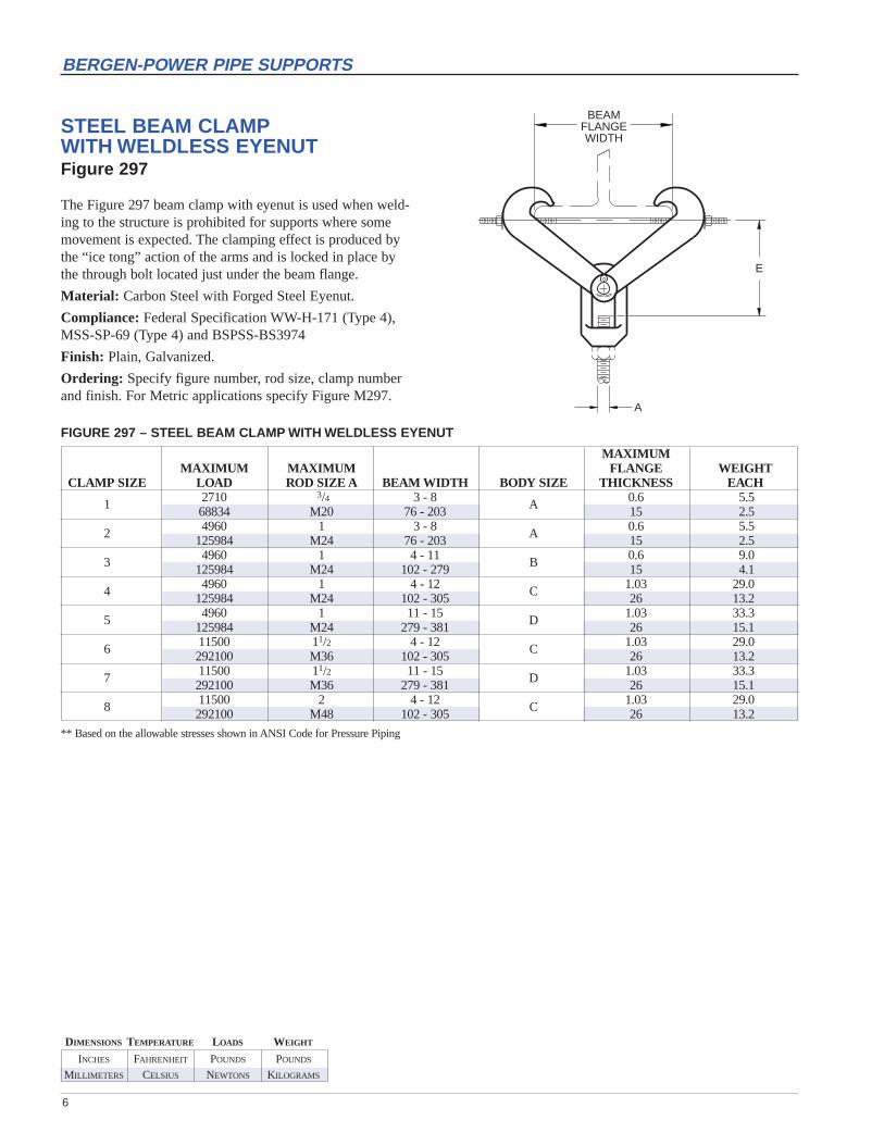
STEEL BEAM CLAMP WITH WELDLESS EYENUTFigure 297
The Figure 297 beam clamp with eyenut is used when weld-ing to the structure is prohibited for supports where somemovement is expected. The clamping effect is produced bythe “ice tong” action of the arms and is locked in place bythe through bolt located just under the beam flange.
Material: Carbon Steel with Forged Steel Eyenut.
Compliance: Federal Specification WW-H-171 (Type 4),MSS-SP-69 (Type 4) and BSPSS-BS3974
Finish: Plain, Galvanized.
Ordering: Specify figure number, rod size, clamp numberand finish. For Metric applications specify Figure M297.
FIGURE 297 – STEEL BEAM CLAMP WITH WELDLESS EYENUT
MAXIMUMMAXIMUM MAXIMUM FLANGE WEIGHT
CLAMP SIZE LOAD ROD SIZE A BEAM WIDTH BODY SIZE THICKNESS EACH
1 2710 3/4 3 - 8 A 0.6 5.568834 M20 76 - 203 15 2.5
2 4960 1 3 - 8 A 0.6 5.5125984 M24 76 - 203 15 2.5
3 4960 1 4 - 11 B 0.6 9.0125984 M24 102 - 279 15 4.1
4 4960 1 4 - 12 C 1.03 29.0125984 M24 102 - 305 26 13.2
5 4960 1 11 - 15 D 1.03 33.3125984 M24 279 - 381 26 15.1
6 11500 11/2 4 - 12 C 1.03 29.0292100 M36 102 - 305 26 13.2
7 11500 11/2 11 - 15 D 1.03 33.3292100 M36 279 - 381 26 15.1
8 11500 2 4 - 12 C 1.03 29.0292100 M48 102 - 305 26 13.2
** Based on the allowable stresses shown in ANSI Code for Pressure Piping

INCHES FAHRENHEIT POUNDS POUNDS
MILLIMETERS CELSIUS NEWTONS KILOGRAMS
DIMENSIONS TEMPERATURE LOADS WEIGHT
7
BERGEN-POWER PIPE SUPPORTS
W T
W T
2 ANCHORDESIGN
4 ANCHORDESIGN
2 ANCHORDESIGN
4 ANCHORDESIGN
CONFIGURATION TYPE 2
CONFIGURATION TYPE 1
J JKW
J JKW
J JKL
J JKL
E1
E
CONCRETE ATTACHMENTFigure 1020
The Figure 1020 Type 1 is forattaching support assemblies toconcrete structures where little orno movement is anticipated. Usedwith a Fig 133 Threaded Rod orFigure 94 All Thread Rod.
The Figure 1020 Type 2 is forattaching support assemblies toconcrete structures where move-ment is anticipated. Used with aFig 279 Weldless Eyenut or Figure93 Welded Eyerod. A two-anchorpattern is used on sizes 3/8" thru5/8" and all others use four anchors.
Material: Carbon Steel.
Finish: Plain.
Ordering: Specify figure number,finish, and rod size. For Metricapplications specify Figure M1020Type 1 or Type 2.
FIGURE 1020 – CONCRETE ATTACHMENT
WGT WGTROD MAX E E 1 H* P J K L KW T W EACH EACHSIZE LOAD W/PIN W/O PIN
3/8 610 21/8 21/4 1/2 1/2 1 4 N/A 5 1/4 4 2.8 2.7M10 2714 54 57 13 13 25 102 N/A 127 6 102 1.3 1.2
1/2 1130 21/8 23/8 5/8 5/8 1 5 N/A 5 3/8 4 4.1 3.9M12 5027 54 60 16 16 25 127 N/A 127 10 102 1.9 1.8
5/8 1810 21/4 21/2 3/4 3/4 1 6 N/A 5 1/2 4 5.8 5.5M16 8052 57 64 19 19 25 152 N/A 127 13 102 2.6 2.5
3/4 2710 21/8 23/8 5/8 7/8 1 5 5 5 3/8 N/A 7.7 7.1M20 12055 54 60 16 22 25 127 127 127 10 N/A 3.5 3.2
7/8 3770 33/8 35/8 7/8 1 11/4 61/2 7 5 5/8 N/A 19.8 18.6M20 16770 86 92 22 25 32 165 165 127 16 N/A 9.0 8.4
1 4960 33/8 35/8 7/8 11/8 11/4 61/2 7 6 5/8 N/A 19.8 18.6M24 22064 86 92 22 29 32 165 165 152 16 N/A 9.0 8.411/4 8000 35/8 33/4 1 13/8 2 8 8 6 3/4 N/A 41.0 38.7M30 35587 92 95 25 35 51 203 203 152 19 N/A 18.6 17.611/2 11630 5 5 11/8 15/8 2 8 8 6 1 N/A 60.0 56.4M36 51735 127 127 29 41 51 203 203 152 25 N/A 27.2 25.613/4 15700 61/4 61/4 13/8 2 2 10 10 7 11/4 N/A 93.6 88.0M42 69840 159 159 35 51 51 254 254 178 32 N/A 42.5 39.9
2 20700 61/2 61/4 13/8 21/4 2 10 10 7 11/4 N/A 100.0 92.0M48 92082 165 159 35 57 51 254 254 178 32 N/A 45.4 41.7
* Holes are 1/8" larger than recommended anchor bolt diameter to allow for installation tolerance.

INCHES FAHRENHEIT POUNDS POUNDS
MILLIMETERS CELSIUS NEWTONS KILOGRAMS
DIMENSIONS TEMPERATURE LOADS WEIGHT
8
BERGEN-POWER PIPE SUPPORTS
WL
HL
TL
HP
KWWP
KL
WP/2
L
J
J
TP
L/2 L/2
E
R
TWO ANCHORS ONLY FORSIZES 3/8" THRU 5/8"
CONCRETE SINGLE LUG PLATEFigure 1022
The Figure 1022 is for attachment to a concrete structurewhere movement is anticipated. A two-anchor pattern isused on sizes 3/8" thru 5/8" and all others use four anchors.Used with the Figure 276 Forged Steel Clevis and Type “C”variable springs.
Material Carbon Steel.
Finish: Plain.
Ordering: Specify figure number, finish, and rod size. For Metric applications specify Figure M1022.
FIGURE 1022 – CONCRETE SINGLE LUG PLATE
ROD MAX WGTSIZE LOAD E H L HP J KL KW L R T P TL WP WL EACH
3/8 610 13/4 1/2 1/2 1 4 - 6 11/4 1/4 1/4 4 21/2 11.6M10 5027 44 13 13 25 102 152 32 6 6 102 64 5.3
1/2 1130 17/8 5/8 5/8 1 5 - 7 11/4 3/8 1/4 4 21/2 11.6M12 5027 48 16 16 25 127 178 32 10 6 102 64 5.3
5/8 1810 2 3/4 3/4 1 6 - 8 11/4 1/2 1/4 4 21/2 11.6M16 8052 51 19 19 25 152 203 32 13 6 102 64 5.3
3/4 2710 21/4 7/8 5/8 1 5 5 7 11/4 1/2 3/8 7 21/2 12.0M20 12055 57 22 16 25 127 127 178 32 13 10 178 64 5.4
7/8 3770 3 1 7/8 1 61/2 61/2 9 11/2 3/4 3/8 9 3 22.0M20 16770 76 25 22 25 165 165 229 38 19 10 229 76 10.0
1 4960 3 11/8 7/8 11/4 8 8 9 11/2 3/4 1/2 9 3 31.9M24 22064 76 29 22 32 203 203 229 38 19 13 229 76 14.511/4 8000 4 13/8 1 2 8 8 12 2 1 5/8 12 4 43.8M30 35587 102 35 25 51 203 203 305 51 25 16 305 102 19.911/2 11630 41/4 15/8 11/8 2 8 8 12 21/2 1 3/4 12 5 45.6M36 51735 108 41 29 51 203 203 305 64 25 19 305 127 20.713/4 15700 41/2 17/8 13/8 2 8 8 12 21/2 11/4 3/4 12 5 55.7M42 69840 114 48 35 51 203 203 305 64 32 19 305 127 25.3
2 20700 51/4 21/4 13/8 2 8 8 12 3 11/4 3/4 12 6 58.2M48 92082 133 57 35 51 203 203 305 76 32 19 305 152 26.4

INCHES FAHRENHEIT POUNDS POUNDS
MILLIMETERS CELSIUS NEWTONS KILOGRAMS
DIMENSIONS TEMPERATURE LOADS WEIGHT
9
BERGEN-POWER PIPE SUPPORTS
A
L
E
HILTI® KWIK-BOLT ANCHORSFigure 1308
The Figure 1308 is used for bolting components to concretestructures. Allows for through drilling applications.
INSTALLATION: Drill holes the same diameter as the boltan deeper than the required embedment. Drive the bolt intothe hole so that at least six threads are below the top surfaceof the fixture. Tighten the nut with the washer in place. Theresistance will increase after the third or fourth turn.
NOTE: Loads listed are based on a safety factor of fourwhen installed in accordance with manufacturer’s recom-mendations. Contact us for higher loads are allowed dueto increased embedment.
Material: High Tensile Steel. (Also available in Stainless Steel).
Finish: Zinc Plated.
Ordering: Specify figure number, diameter and length.For Metric applications specify Figure M1308.
FIGURE 1308 – HILTI KWIK-BOLT ANCHORS
4000 PSI CONCRETEBOLT SAFE WORKING LOAD L D(Embd.) T LDIA. TENSION SHEAR
13/444
1/4 365 650 21/4 11/8 3/4M6 1624 2891 57 29 19
31/48321/4 7/857 22
3/8 935 590 3 15/8 11/8M10 4159 2625 76 41 29
33/4 11/895 295 11/8
127 2923/470
1/2 1375 2080 33/4 21/4 11/4M12 6117 9253 95 57 32
41/211451/214033/495
5/8 1650 2900 43/4 23/4 23/4M16 7340 12900 121 70 70
61527
17843/4121
3/4 2535 4280 51/2 31/4 11/2M20 11277 19039 140 83 38
71788
2031 4000 6700 6 41/2 21/4
M24 17794 29804 152 114 579
22911/4 5750 8900 9 51/2 31/4M30 25578 39591 229 140 83
INCHES FAHRENHEIT POUNDS POUNDS
MILLIMETERS CELSIUS NEWTONS KILOGRAMS
DIMENSIONS TEMPERATURE LOADS WEIGHT
10
BERGEN-POWER PIPE SUPPORTS
A
L
E
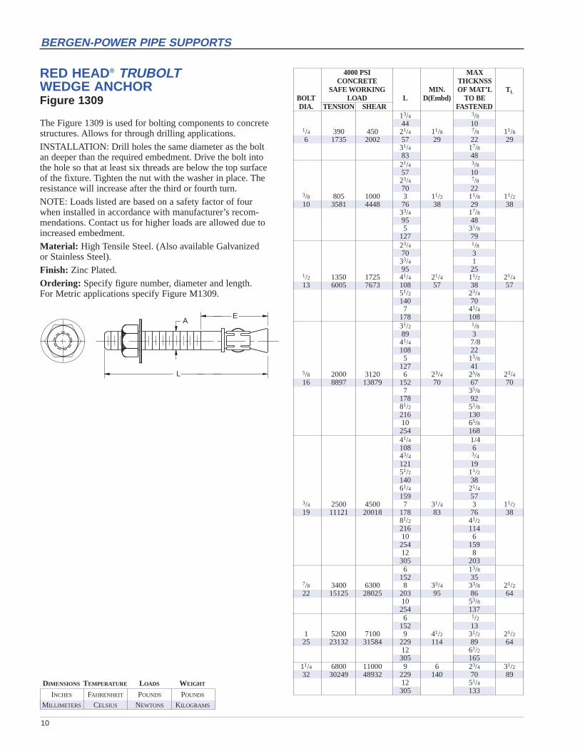
RED HEAD® TRUBOLT WEDGE ANCHORFigure 1309
The Figure 1309 is used for bolting components to concretestructures. Allows for through drilling applications.
INSTALLATION: Drill holes the same diameter as the boltan deeper than the required embedment. Drive the bolt intothe hole so that at least six threads are below the top surfaceof the fixture. Tighten the nut with the washer in place. Theresistance will increase after the third or fourth turn.
NOTE: Loads listed are based on a safety factor of fourwhen installed in accordance with manufacturer’s recom-mendations. Contact us for higher loads are allowed due toincreased embedment.
Material: High Tensile Steel. (Also available Galvanized or Stainless Steel).
Finish: Zinc Plated.
Ordering: Specify figure number, diameter and length. For Metric applications specify Figure M1309.
4000 PSI MAXCONCRETE THCKNSS
SAFE WORKING MIN. OF MAT’L T L
BOLT LOAD L D(Embd) TO BEDIA. TENSION SHEAR FASTENED
13/4 3/844 10
1/4 390 450 21/4 11/8 7/8 11/86 1735 2002 57 29 22 29
31/4 17/883 4821/4 3/857 1023/4 7/870 22
3/8 805 1000 3 11/2 11/8 11/210 3581 4448 76 38 29 38
33/4 17/895 485 31/8
127 7923/4 1/870 333/4 195 25
1/2 1350 1725 41/4 21/4 11/2 21/413 6005 7673 108 57 38 57
51/2 23/4140 707 41/4
178 10831/2 1/889 341/4 7/8108 225 15/8
127 415/8 2000 3120 6 23/4 25/8 23/416 8897 13879 152 70 67 70
7 35/8178 9281/2 51/8216 13010 65/8254 16841/4 1/4108 643/4 3/4121 1951/2 11/2140 3861/4 21/4159 57
3/4 2500 4500 7 31/4 3 11/219 11121 20018 178 83 76 38
81/2 41/2216 11410 6254 15912 8305 2036 13/8
152 357/8 3400 6300 8 33/4 33/8 21/222 15125 28025 203 95 86 64
10 53/8254 1376 1/2
152 131 5200 7100 9 41/2 31/2 21/225 23132 31584 229 114 89 64
12 61/2305 165
11/4 6800 11000 9 6 23/4 31/232 30249 48932 229 140 70 89
12 51/4305 133

INCHES FAHRENHEIT POUNDS POUNDS
MILLIMETERS CELSIUS NEWTONS KILOGRAMS
DIMENSIONS TEMPERATURE LOADS WEIGHT
11
BERGEN-POWER PIPE SUPPORTS
D
L
HW
N
E
M
END PLATE OMITTED FOR CLARITY IN THIS VIEW
T
HORIZONTAL TRAVELERFigure 7054
The Figure 7054 is used to accommodate horizontal pipingmovement that exceeds the normal 4° misalignment limits.It is to be welded all around to the building structural member. Each unit is compact, self-contained and ready for installation. The design minimizes friction and dustaccumulation thus assuring proper functioning.
FIGURE 7054 – HORIZONTAL TRAVELER
MAX WEIGHTSIZE LOAD D E H (Max.) L M N T W EACH
1 3770 53/8 41/8 11/8 15 45/8 21/2 3/4 21/2 1516770 137 105 29 381 117 64 19 64 7
2 6230 77/8 6 13/8 161/2 63/4 31/2 3/4 31/2 3427714 200 152 35 419 171 89 19 89 15
3 11630 101/2 8 13/4 173/4 81/2 5 1 5 7751735 267 203 44 451 216 127 25 127 35
4 20700 121/2 91/2 23/8 193/4 10 6 11/2 6 12092082 318 241 60 502 254 152 38 152 54
Material: Carbon Steel with self lubricating bushings.
Finish: Plain.
Ordering: Specify figure number and size. For Metric applications specify Figure M7054.
C
F
H
D
L
STANDARD HEX BOLTFigure 160
American Standard hex head bolts are stocked for immedi-ate shipment in sizes 3/8" to 11/2" in various lengths. Lengthis measured from under the head to end.
Material: ASTM A-563 Grade A (Alloy and Stainless Steelgrades are Available).
Finish: Plain, Electro-galvanized, Hot-Dip Galvanized.
Ordering: Specify figure number, finish and tap size.For Metric applications specify M160.
INCHES FAHRENHEIT POUNDS POUNDS
MILLIMETERS CELSIUS NEWTONS KILOGRAMS
DIMENSIONS TEMPERATURE LOADS WEIGHT
12
BERGEN-POWER PIPE SUPPORTS
B
TL
A
SPECIFY
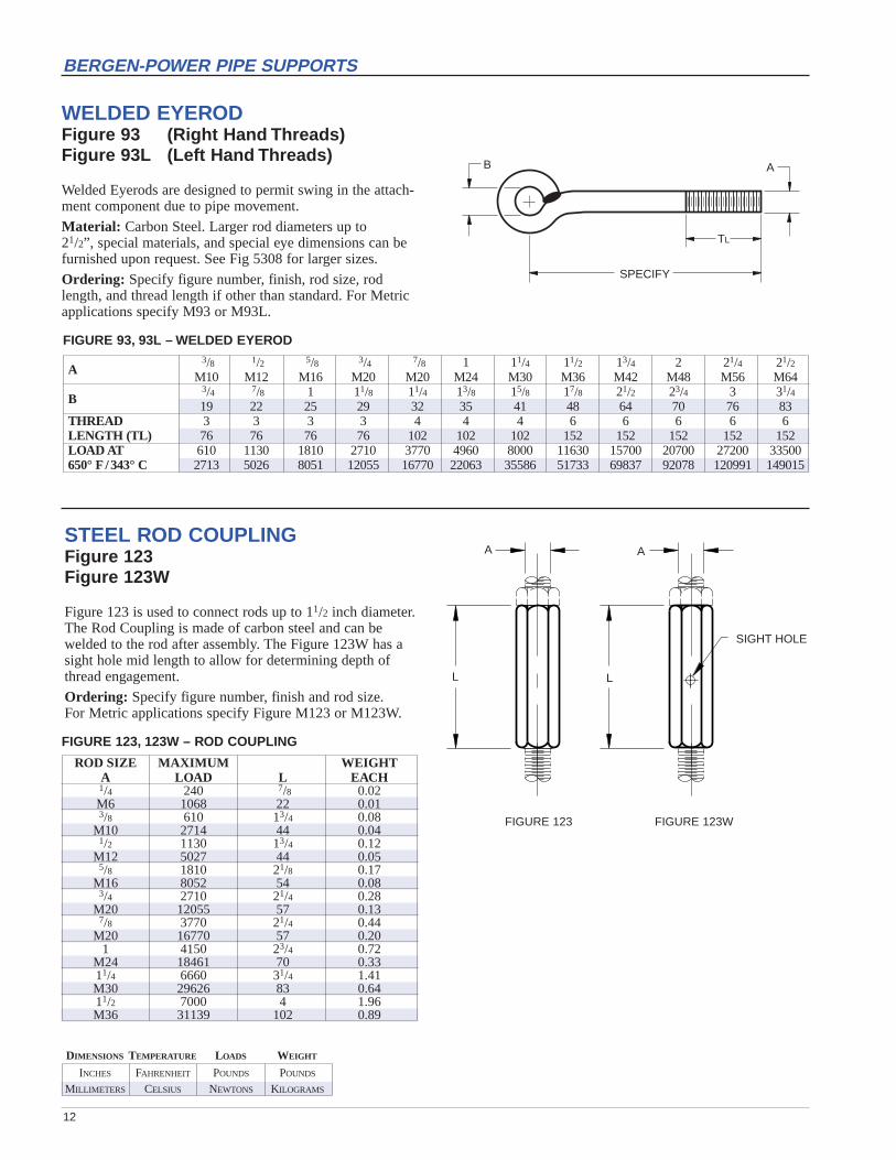
WELDED EYERODFigure 93 (Right Hand Threads)Figure 93L (Left Hand Threads)
Welded Eyerods are designed to permit swing in the attach-ment component due to pipe movement.
Material: Carbon Steel. Larger rod diameters up to 21/2”, special materials, and special eye dimensions can befurnished upon request. See Fig 5308 for larger sizes.
Ordering: Specify figure number, finish, rod size, rodlength, and thread length if other than standard. For Metricapplications specify M93 or M93L.
A
L
A
L
SIGHT HOLE
STEEL ROD COUPLINGFigure 123Figure 123W
Figure 123 is used to connect rods up to 11/2 inch diameter.The Rod Coupling is made of carbon steel and can be welded to the rod after assembly. The Figure 123W has asight hole mid length to allow for determining depth ofthread engagement.
Ordering: Specify figure number, finish and rod size.For Metric applications specify Figure M123 or M123W.
FIGURE 123, 123W – ROD COUPLING
ROD SIZE MAXIMUM WEIGHTA LOAD L EACH1/4 240 7/8 0.02M6 1068 22 0.013/8 610 13/4 0.08
M10 2714 44 0.041/2 1130 13/4 0.12
M12 5027 44 0.055/8 1810 21/8 0.17
M16 8052 54 0.083/4 2710 21/4 0.28
M20 12055 57 0.137/8 3770 21/4 0.44
M20 16770 57 0.201 4150 23/4 0.72
M24 18461 70 0.3311/4 6660 31/4 1.41M30 29626 83 0.6411/2 7000 4 1.96M36 31139 102 0.89
FIGURE 123 FIGURE 123W
A3/8 1/2 5/8 3/4 7/8 1 11/4 11/2 13/4 2 21/4 21/2
M10 M12 M16 M20 M20 M24 M30 M36 M42 M48 M56 M64
B3/4 7/8 1 11/8 11/4 13/8 15/8 17/8 21/2 23/4 3 31/419 22 25 29 32 35 41 48 64 70 76 83
THREAD 3 3 3 3 4 4 4 6 6 6 6 6LENGTH (TL) 76 76 76 76 102 102 102 152 152 152 152 152LOAD AT 610 1130 1810 2710 3770 4960 8000 11630 15700 20700 27200 33500650° F /343° C 2713 5026 8051 12055 16770 22063 35586 51733 69837 92078 120991 149015
FIGURE 93, 93L – WELDED EYEROD

INCHES FAHRENHEIT POUNDS POUNDS
MILLIMETERS CELSIUS NEWTONS KILOGRAMS
DIMENSIONS TEMPERATURE LOADS WEIGHT
13
BERGEN-POWER PIPE SUPPORTS
A
SPECIFY
ALL-THREAD HANGER RODFigure 94Figure 94SS
This product has a standard machine thread running itsentire length. It is particularly useful when exact rodlengths are questionable.
Material: Figure 94 is made of carbon steel while Figure94SS is available in either 304 or 316 stainless steel.Available in precut six, ten, and twelve foot lengths. Can becut to suit customer need upon request.
Finish: Plain, Electro-Galvanized, or Hot-Dip Galvanized
Ordering: Specify figure number, finish, rod size, and length.For Metric applications specify Figure M94 or M94SS.
FIGURE 94, 94SS – ALL-THREAD HANGER ROD
DIAMETER MAXIMUM WEIGHTA LOAD PER FOOT3/8 610 0.30
M10 2714 0.141/2 1130 0.53
M12 5027 0.245/8 1810 0.84
M16 8052 0.383/4 2710 1.20
M20 12055 0.547/8 3700 1.70
M20 16459 0.771 4960 2.30
M24 22064 1.0411/4 8000 3.60M30 35587 1.6311/2 11600 5.10M36 51601 2.31
FIGURE 133, 133L – MACHINE THREAD RODS
DIAMETER THREAD LOAD ATA LENGTH 650° F / 343° C3/8 3 610
M10 76 27131/2 3 1130
M12 76 50265/8 3 1810
M16 76 80513/4 3 2710
M20 76 120557/8 4 3770
M20 102 167701 4 4960
M24 102 2206311/4 4 8000M30 102 3558611/2 6 11630M36 152 5173313/4 6 15700M42 152 69837
2 6 20700M48 152 9207821/4 6 27200M56 152 12099121/2 6 33500M64 152 14901523/4 6 41580M72 152 184956
3 6 50580M80 152 22499031/4 6 60480M80 152 26902731/2 6 71280M90 152 31706833/4 6 82890M95 152 368711
4 6 95400M100 152 424358
D A D
B SPECIFY
MACHINE THREAD RODSFigure 133(Right Hand Threads Both Ends)
Figure 133L(Right Hand and Left Hand Thread)
Furnished with UNC threads this product is made from carbon steel.
Maximum loads given are rated for up to 650° F (343° C).
Material: Carbon Steel (Stainless Steel is Available).
Finish: Plain, Electro-galvanized, Hot-Dip Galvanized.
Ordering: Specify material if other than carbon steel,figure number, finish, rod diameter, and length, and threadlength if other than standard. For Metric applications specify M133 or M133L.
INCHES FAHRENHEIT POUNDS POUNDS
MILLIMETERS CELSIUS NEWTONS KILOGRAMS
DIMENSIONS TEMPERATURE LOADS WEIGHT
14
BERGEN-POWER PIPE SUPPORTS
B 6"
A
3" RODTAKE OUT
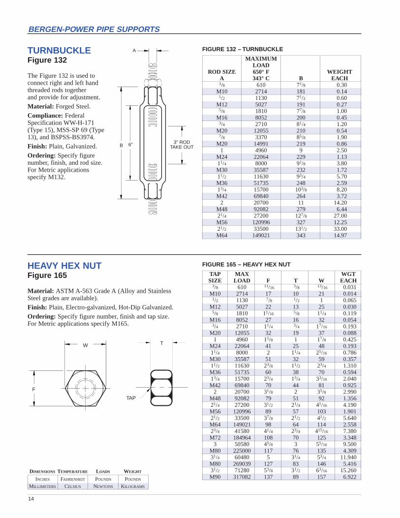
TURNBUCKLEFigure 132
The Figure 132 is used to connect right and left handthreaded rods together and provide for adjustment.
Material: Forged Steel.
Compliance: FederalSpecification WW-H-171 (Type 15), MSS-SP 69 (Type13), and BSPSS-BS3974.
Finish: Plain, Galvanized.
Ordering: Specify figure number, finish, and rod size. For Metric applications specify M132.
MAXIMUMLOAD
ROD SIZE 650° F WEIGHTA 343° C B EACH3/8 610 71/8 0.30
M10 2714 181 0.141/2 1130 71/2 0.60
M12 5027 191 0.275/8 1810 77/8 1.00
M16 8052 200 0.453/4 2710 81/4 1.20
M20 12055 210 0.547/8 3370 85/8 1.90
M20 14991 219 0.861 4960 9 2.50
M24 22064 229 1.1311/4 8000 91/8 3.80M30 35587 232 1.7211/2 11630 93/4 5.70M36 51735 248 2.5913/4 15700 103/8 8.20M42 69840 264 3.72
2 20700 11 14.20M48 92082 279 6.4421/4 27200 127/8 27.00M56 120996 327 12.2521/2 33500 131/2 33.00M64 149021 343 14.97
W
F
T
TAP
HEAVY HEX NUTFigure 165
Material: ASTM A-563 Grade A (Alloy and Stainless Steel grades are available).
Finish: Plain, Electro-galvanized, Hot-Dip Galvanized.
Ordering: Specify figure number, finish and tap size.For Metric applications specify M165.
TAP MAX WGTSIZE LOAD F T W EACH
3/8 610 11/16 3/8 13/16 0.031M10 2714 17 10 21 0.014
1/2 1130 7/8 1/2 1 0.065M12 5027 22 13 25 0.030
5/8 1810 11/16 5/8 11/4 0.119M16 8052 27 16 32 0.054
3/4 2710 11/4 3/4 17/16 0.193M20 12055 32 19 37 0.088
1 4960 15/8 1 17/8 0.425M24 22064 41 25 48 0.19311/4 8000 2 11/4 25/16 0.786M30 35587 51 32 59 0.35711/2 11630 23/8 11/2 23/4 1.310M36 51735 60 38 70 0.59413/4 15700 23/4 13/4 33/16 2.040M42 69840 70 44 81 0.925
2 20700 31/8 2 35/8 2.990M48 92082 79 51 92 1.35621/4 27200 31/2 21/4 41/16 4.190M56 120996 89 57 103 1.90121/2 33500 37/8 21/2 41/2 5.640M64 149021 98 64 114 2.55823/4 41580 41/4 23/4 415/16 7.380M72 184964 108 70 125 3.348
3 50580 45/8 3 55/16 9.500M80 225000 117 76 135 4.30931/4 60480 5 31/4 53/4 11.940M80 269039 127 83 146 5.41631/2 71280 53/8 31/2 63/16 15.260M90 317082 137 89 157 6.922
FIGURE 165 – HEAVY HEX NUT
FIGURE 132 – TURNBUCKLE
INCHES FAHRENHEIT POUNDS POUNDS
MILLIMETERS CELSIUS NEWTONS KILOGRAMS
DIMENSIONS TEMPERATURE LOADS WEIGHT
15
BERGEN-POWER PIPE SUPPORTS
WA
P
D
N
TAP
T
GRIP
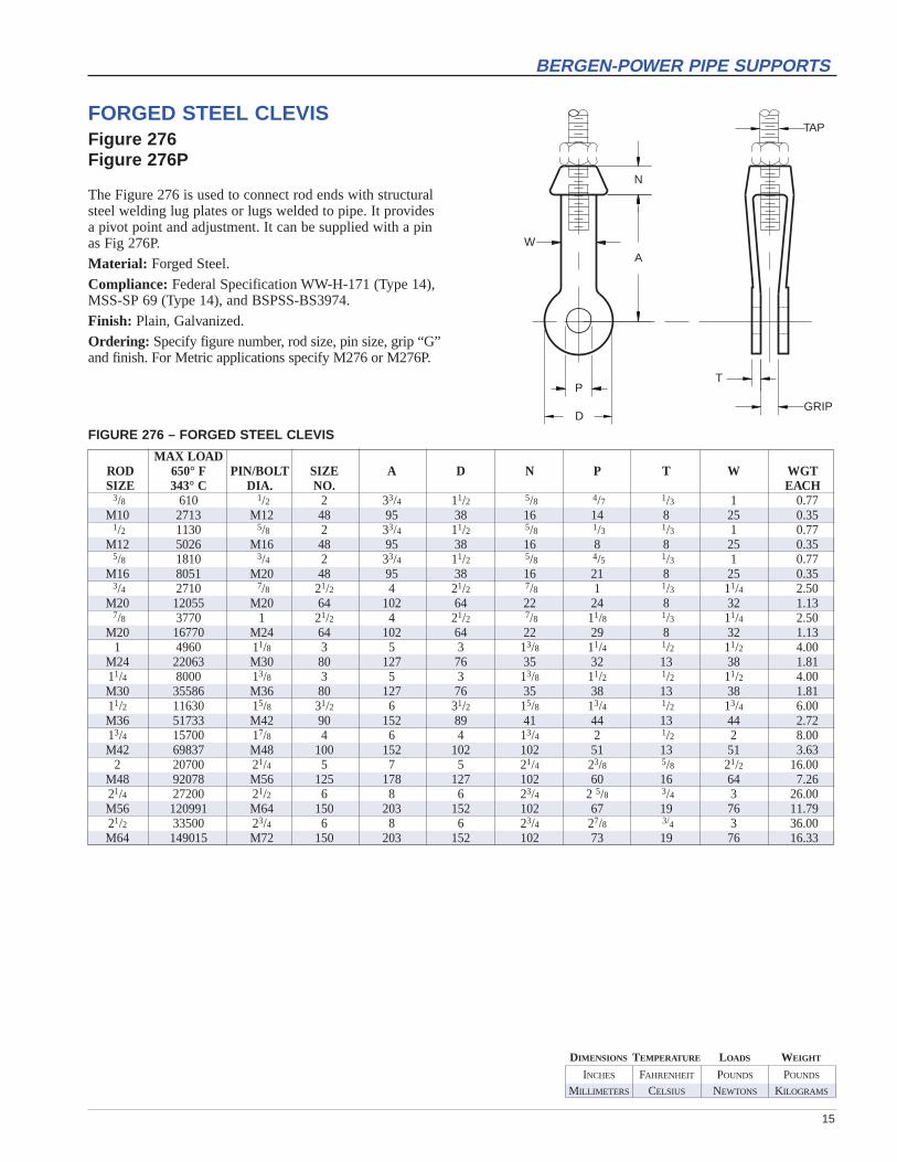
FORGED STEEL CLEVISFigure 276Figure 276P
The Figure 276 is used to connect rod ends with structuralsteel welding lug plates or lugs welded to pipe. It providesa pivot point and adjustment. It can be supplied with a pinas Fig 276P.
Material: Forged Steel.
Compliance: Federal Specification WW-H-171 (Type 14),MSS-SP 69 (Type 14), and BSPSS-BS3974.
Finish: Plain, Galvanized.
Ordering: Specify figure number, rod size, pin size, grip “G”and finish. For Metric applications specify M276 or M276P.
FIGURE 276 – FORGED STEEL CLEVIS
MAX LOADROD 650° F PIN/BOLT SIZE A D N P T W WGTSIZE 343° C DIA. NO. EACH
3/8 610 1/2 2 33/4 11/2 5/8 4/7 1/3 1 0.77M10 2713 M12 48 95 38 16 14 8 25 0.35
1/2 1130 5/8 2 33/4 11/2 5/8 1/3 1/3 1 0.77M12 5026 M16 48 95 38 16 8 8 25 0.35
5/8 1810 3/4 2 33/4 11/2 5/8 4/5 1/3 1 0.77M16 8051 M20 48 95 38 16 21 8 25 0.35
3/4 2710 7/8 21/2 4 21/2 7/8 1 1/3 11/4 2.50M20 12055 M20 64 102 64 22 24 8 32 1.13
7/8 3770 1 21/2 4 21/2 7/8 11/8 1/3 11/4 2.50M20 16770 M24 64 102 64 22 29 8 32 1.13
1 4960 11/8 3 5 3 13/8 11/4 1/2 11/2 4.00M24 22063 M30 80 127 76 35 32 13 38 1.8111/4 8000 13/8 3 5 3 13/8 11/2 1/2 11/2 4.00M30 35586 M36 80 127 76 35 38 13 38 1.8111/2 11630 15/8 31/2 6 31/2 15/8 13/4 1/2 13/4 6.00M36 51733 M42 90 152 89 41 44 13 44 2.7213/4 15700 17/8 4 6 4 13/4 2 1/2 2 8.00M42 69837 M48 100 152 102 102 51 13 51 3.63
2 20700 21/4 5 7 5 21/4 23/8 5/8 21/2 16.00M48 92078 M56 125 178 127 102 60 16 64 7.2621/4 27200 21/2 6 8 6 23/4 2 5/8 3/4 3 26.00M56 120991 M64 150 203 152 102 67 19 76 11.7921/2 33500 23/4 6 8 6 23/4 27/8 3/4 3 36.00M64 149015 M72 150 203 152 102 73 19 76 16.33

INCHES FAHRENHEIT POUNDS POUNDS
MILLIMETERS CELSIUS NEWTONS KILOGRAMS
DIMENSIONS TEMPERATURE LOADS WEIGHT
16
BERGEN-POWER PIPE SUPPORTS
A
F
E
CL
B
C
D
FORGED WELDLESS EYENUTFigure 279Figure 279L
The Figure 279 is used to connect rod ends with structuralsteel welded beam attachments or pipe clamps as a substitutefor a welded eyerod. It provides a pivot point and adjustment.It can also be supplied tapped left hand as Fig 279L.
Material: Forged Steel.
Compliance: Federal Specification WW-H-171 (Type 17),MSS-SP 69 (Type 17), and BSPSS-BS3974.
Finish: Plain, Galvanized.
Ordering: Specify figure number, rod size and finish. For Metric applications specify M279 or M279L.
FIGURE 279 – WELDLESS EYENUT
ROD TAP MAX LOAD WEIGHTA 650° F / 343 °C B C D E F EACH3/8 610 1/2 3/4 5/16 11/4 1 0.20
M10 2714 13 19 8 32 25 0.091/2 1130 5/8 7/8 3/8 11/2 1 0.31
M12 5027 16 22 10 38 25 0.145/8 1810 3/4 13/8 1/2 17/8 1 0.55
M16 8052 19 35 13 48 25 0.253/4 2710 3/4 11/2 5/8 21/2 1 1.00
M20 12055 19 38 16 64 25 0.457/8 3770 1 2 3/4 21/2 13/8 1.55
M20 14991 25 51 19 64 35 0.701 4960 11/8 2 3/4 21/2 13/4 2.45
M24 22064 29 51 19 64 44 1.1111/4 8000 11/4 23/8 1 33/8 13/4 3.75M30 35587 32 60 25 86 44 1.7011/2 11630 11/4 23/8 1 33/8 13/4 6.75M36 51735 32 60 25 86 44 3.0613/4 15700 21/4 4 11/2 61/4 31/4 16.40M42 69840 57 102 38 159 83 7.44
2 20700 21/4 4 11/2 61/4 31/4 16.75M48 92082 57 102 38 159 83 7.6021/4 27200 21/4 4 11/2 61/4 31/4 16.75M56 120996 57 102 38 159 83 7.6021/2 33500 21/4 4 11/2 61/4 31/4 16.75M64 149021 57 102 38 159 83 7.60
INCHES FAHRENHEIT POUNDS POUNDS
MILLIMETERS CELSIUS NEWTONS KILOGRAMS
DIMENSIONS TEMPERATURE LOADS WEIGHT
17
BERGEN-POWER PIPE SUPPORTS
A
D DGAP G
SIGHT HOLE TYP.
E
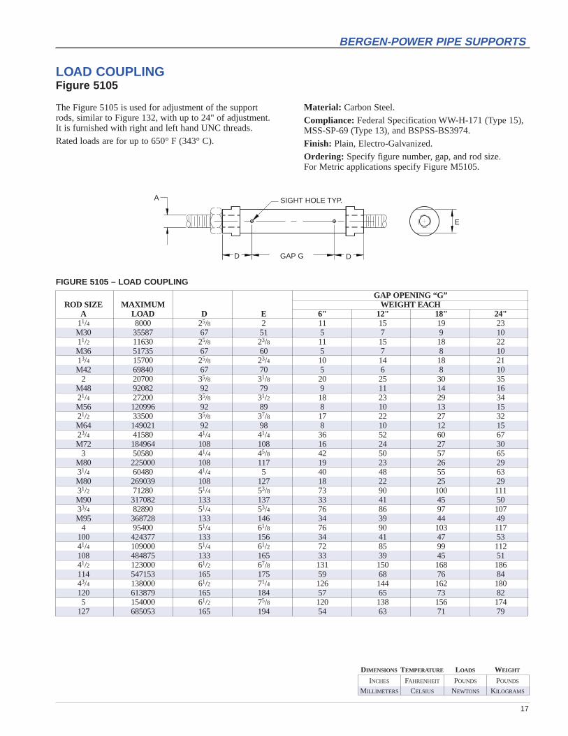
LOAD COUPLINGFigure 5105
The Figure 5105 is used for adjustment of the support rods, similar to Figure 132, with up to 24" of adjustment. It is furnished with right and left hand UNC threads.
Rated loads are for up to 650° F (343° C).
FIGURE 5105 – LOAD COUPLING
GAP OPENING “G”ROD SIZE MAXIMUM WEIGHT EACH
A LOAD D E 6" 12" 18" 24"11/4 8000 25/8 2 11 15 19 23M30 35587 67 51 5 7 9 1011/2 11630 25/8 23/8 11 15 18 22M36 51735 67 60 5 7 8 1013/4 15700 25/8 23/4 10 14 18 21M42 69840 67 70 5 6 8 10
2 20700 35/8 31/8 20 25 30 35M48 92082 92 79 9 11 14 1621/4 27200 35/8 31/2 18 23 29 34M56 120996 92 89 8 10 13 1521/2 33500 35/8 37/8 17 22 27 32M64 149021 92 98 8 10 12 1523/4 41580 41/4 41/4 36 52 60 67M72 184964 108 108 16 24 27 30
3 50580 41/4 45/8 42 50 57 65M80 225000 108 117 19 23 26 2931/4 60480 41/4 5 40 48 55 63M80 269039 108 127 18 22 25 2931/2 71280 51/4 53/8 73 90 100 111M90 317082 133 137 33 41 45 5033/4 82890 51/4 53/4 76 86 97 107M95 368728 133 146 34 39 44 49
4 95400 51/4 61/8 76 90 103 117100 424377 133 156 34 41 47 5341/4 109000 51/4 61/2 72 85 99 112108 484875 133 165 33 39 45 5141/2 123000 61/2 67/8 131 150 168 186114 547153 165 175 59 68 76 8443/4 138000 61/2 71/4 126 144 162 180120 613879 165 184 57 65 73 825 154000 61/2 75/8 120 138 156 174
127 685053 165 194 54 63 71 79
Material: Carbon Steel.
Compliance: Federal Specification WW-H-171 (Type 15),MSS-SP-69 (Type 13), and BSPSS-BS3974.
Finish: Plain, Electro-Galvanized.
Ordering: Specify figure number, gap, and rod size. For Metric applications specify Figure M5105.
INCHES FAHRENHEIT POUNDS POUNDS
MILLIMETERS CELSIUS NEWTONS KILOGRAMS
DIMENSIONS TEMPERATURE LOADS WEIGHT
18
BERGEN-POWER PIPE SUPPORTS
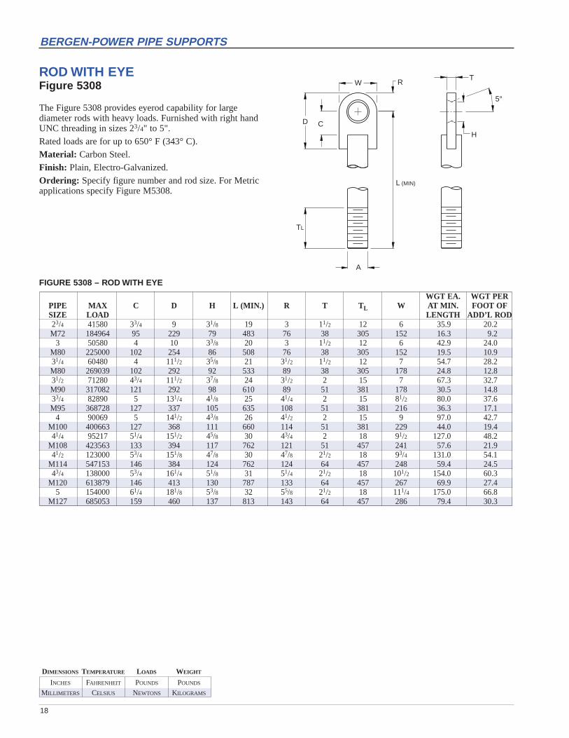
ROD WITH EYEFigure 5308
The Figure 5308 provides eyerod capability for large diameter rods with heavy loads. Furnished with right handUNC threading in sizes 23/4" to 5".
Rated loads are for up to 650° F (343° C).
Material: Carbon Steel.
Finish: Plain, Electro-Galvanized.
Ordering: Specify figure number and rod size. For Metricapplications specify Figure M5308.
FIGURE 5308 – ROD WITH EYE
WGT EA. WGT PERPIPE MAX C D H L (MIN.) R T T L W AT MIN. FOOT OFSIZE LOAD LENGTH ADD’L ROD23/4 41580 33/4 9 31/8 19 3 11/2 12 6 35.9 20.2M72 184964 95 229 79 483 76 38 305 152 16.3 9.2
3 50580 4 10 33/8 20 3 11/2 12 6 42.9 24.0M80 225000 102 254 86 508 76 38 305 152 19.5 10.931/4 60480 4 111/2 35/8 21 31/2 11/2 12 7 54.7 28.2M80 269039 102 292 92 533 89 38 305 178 24.8 12.831/2 71280 43/4 111/2 37/8 24 31/2 2 15 7 67.3 32.7M90 317082 121 292 98 610 89 51 381 178 30.5 14.833/4 82890 5 131/4 41/8 25 41/4 2 15 81/2 80.0 37.6M95 368728 127 337 105 635 108 51 381 216 36.3 17.1
4 90069 5 141/2 43/8 26 41/2 2 15 9 97.0 42.7M100 400663 127 368 111 660 114 51 381 229 44.0 19.441/4 95217 51/4 151/2 45/8 30 43/4 2 18 91/2 127.0 48.2
M108 423563 133 394 117 762 121 51 457 241 57.6 21.941/2 123000 53/4 151/8 47/8 30 47/8 21/2 18 93/4 131.0 54.1
M114 547153 146 384 124 762 124 64 457 248 59.4 24.543/4 138000 53/4 161/4 51/8 31 51/4 21/2 18 101/2 154.0 60.3
M120 613879 146 413 130 787 133 64 457 267 69.9 27.45 154000 61/4 181/8 53/8 32 55/8 21/2 18 111/4 175.0 66.8
M127 685053 159 460 137 813 143 64 457 286 79.4 30.3
D C
W R
TL
A
L (MIN)
H
T
5°
INCHES FAHRENHEIT POUNDS POUNDS
MILLIMETERS CELSIUS NEWTONS KILOGRAMS
DIMENSIONS TEMPERATURE LOADS WEIGHT
19
BERGEN-POWER PIPE SUPPORTS
CF
E
BGSTOCK
SIZE
D
H
CL
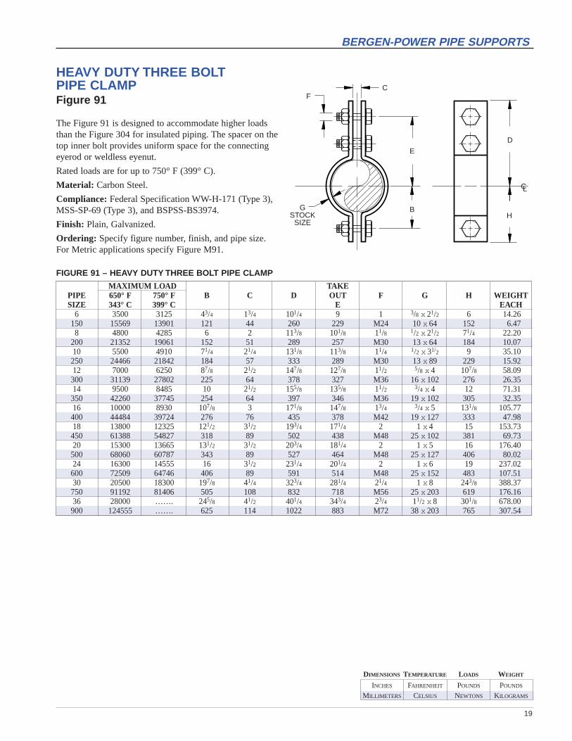
HEAVY DUTY THREE BOLT PIPE CLAMPFigure 91
The Figure 91 is designed to accommodate higher loadsthan the Figure 304 for insulated piping. The spacer on thetop inner bolt provides uniform space for the connectingeyerod or weldless eyenut.
Rated loads are for up to 750° F (399° C).
Material: Carbon Steel.
Compliance: Federal Specification WW-H-171 (Type 3),MSS-SP-69 (Type 3), and BSPSS-BS3974.
Finish: Plain, Galvanized.
Ordering: Specify figure number, finish, and pipe size. For Metric applications specify Figure M91.
MAXIMUM LOAD TAKEPIPE 650° F 750° F B C D OUT F G H WEIGHTSIZE 343° C 399° C E EACH
6 3500 3125 43/4 13/4 101/4 9 1 3/8 x 21/2 6 14.26150 15569 13901 121 44 260 229 M24 10 x 64 152 6.478 4800 4285 6 2 113/8 101/8 11/8 1/2 x 21/2 71/4 22.20
200 21352 19061 152 51 289 257 M30 13 x 64 184 10.0710 5500 4910 71/4 21/4 131/8 113/8 11/4 1/2 x 31/2 9 35.10250 24466 21842 184 57 333 289 M30 13 x 89 229 15.9212 7000 6250 87/8 21/2 147/8 127/8 11/2 5/8 x 4 107/8 58.09300 31139 27802 225 64 378 327 M36 16 x 102 276 26.3514 9500 8485 10 21/2 155/8 135/8 11/2 3/4 x 4 12 71.31350 42260 37745 254 64 397 346 M36 19 x 102 305 32.3516 10000 8930 107/8 3 171/8 147/8 13/4 3/4 x 5 131/8 105.77400 44484 39724 276 76 435 378 M42 19 x 127 333 47.9818 13800 12325 121/2 31/2 193/4 171/4 2 1 x 4 15 153.73450 61388 54827 318 89 502 438 M48 25 x 102 381 69.7320 15300 13665 131/2 31/2 203/4 181/4 2 1 x 5 16 176.40500 68060 60787 343 89 527 464 M48 25 x 127 406 80.0224 16300 14555 16 31/2 231/4 201/4 2 1 x 6 19 237.02600 72509 64746 406 89 591 514 M48 25 x 152 483 107.5130 20500 18300 197/8 41/4 323/4 281/4 21/4 1 x 8 243/8 388.37750 91192 81406 505 108 832 718 M56 25 x 203 619 176.1636 28000 ……. 245/8 41/2 401/4 343/4 23/4 11/2 x 8 301/8 678.00900 124555 ……. 625 114 1022 883 M72 38 x 203 765 307.54
FIGURE 91 – HEAVY DUTY THREE BOLT PIPE CLAMP
INCHES FAHRENHEIT POUNDS POUNDS
MILLIMETERS CELSIUS NEWTONS KILOGRAMS
DIMENSIONS TEMPERATURE LOADS WEIGHT
20
BERGEN-POWER PIPE SUPPORTS
CF
E
BGSTOCK
SIZE
D
H
CL
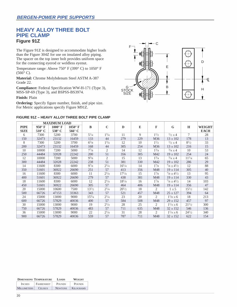
HEAVY ALLOY THREE BOLT PIPE CLAMPFigure 91Z
The Figure 91Z is designed to accommodate higher loadsthan the Figure 304Z for use on insulated alloy piping. The spacer on the top inner bolt provides uniform space for the connecting eyerod or weldless eyenut.
Temperature range: Above 750° F (399° C) to 1050° F(566° C).
Material: Chrome Molybdenum Steel ASTM A-387 Grade 22.
Compliance: Federal Specification WW-H-171 (Type 3),MSS-SP-69 (Type 3), and BSPSS-BS3974.
Finish: Plain
Ordering: Specify figure number, finish, and pipe size.For Metric applications specify Figure M91Z.
MAXIMUM LOADPIPE 950° F 1000° F 1050° F B C D E F G H WEIGHTSIZE 510° C 538° C 566° C EACH
6 7300 5200 3700 51/4 13/4 11 9 11/2 1/2 x 4 7 28150 32473 23132 16459 133 44 279 229 M36 13 x 102 178 138 7300 5200 3700 65/8 13/4 12 10 11/2 1/2 x 4 81/2 33
200 32473 23132 16459 168 44 305 254 M36 13 x 102 216 1510 10000 7200 5000 77/8 2 14 12 13/4 3/4 x 4 10 53250 44484 32028 22242 200 51 356 305 M42 19 x 102 254 2412 10000 7200 5000 93/8 2 15 13 13/4 3/4 x 4 111/4 65300 44484 32028 22242 238 51 381 330 M42 19 x 102 286 2914 11600 8300 6000 97/8 21/4 161/4 14 17/8 7/8 x 41/2 12 88350 51601 36922 26690 251 57 413 356 M48 19 x 114 305 4016 11600 8300 6000 11 21/4 171/4 15 17/8 7/8 x 41/2 13 95400 51601 36922 26690 279 57 438 381 M48 19 x 114 330 4318 11600 8300 6000 12 21/4 181/4 16 17/8 7/8 x 41/2 14 103450 51601 36922 26690 305 57 464 406 M48 19 x 114 356 4720 15000 10600 7500 131/2 21/4 201/2 18 2 1 x 5 151/2 142500 66726 47153 33363 343 57 521 457 M48 25 x 127 394 6424 15000 13000 9000 153/4 21/4 23 20 2 11/8 x 6 18 213600 66726 57829 40036 400 57 584 508 M48 29 x 152 457 9730 15000 13000 9000 19 21/4 28 25 2 11/4 x 6 211/2 300750 66726 57829 40036 483 57 711 635 M48 32 x 152 546 13636 15000 13000 9000 22 21/4 31 28 2 11/4 x 6 241/2 340900 66726 57829 40036 559 57 787 711 M48 32 x 152 622 154
FIGURE 91Z – HEAVY ALLOY THREE BOLT PIPE CLAMP

21
BERGEN-POWER PIPE SUPPORTS
CLEVIS HANGERFigure 100Figure 100SS
Designed to support non-insulated, stationary lines from above allowing for approximately 1" to 11/2" of vertical adjustment after the pipe is inplace. The lower nut (not furnished) adjusts the pipe line to the proper elevation, the top nut (not furnished) prevents loosening due to vibration,and must be tightened securely to assure proper hanger performance.
Hangers for 12" pipe size and larger are furnished with spreaders on thecross bolts.
Rated Loads are for up to 650° F (343° C).
Material: Carbon Steel (Also available in Stainless Steel as Figure 100SS).
Compliance: Federal Specification WW-H-171E Type 1, MSS-SP-69 (Type 1) and BSPSS-BS3974.
Finish: Plain, Galvanized, Plastic Coated.
Ordering: Specify figure number, finish and pipe size. For Metric applications specify Figure M100 OR M100SS.
ROD STEEL STEELPIPE MAXIMUM TAKE OUT SIZE SIZE WEIGHTSIZE LOAD A B C E UPPER LOWER EACH
1/2 610 3/8 23/4 31/8 17/8 11gax 1 11gax 1 0.2715 2714 M10 70 79 48 3x 25 3x 25 0.123/4 610 3/8 21/8 23/4 11/2 11ga x 1 11gax 1 0.2920 2714 M10 54 70 38 3x 25 3x 25 0.131 610 3/8 3 33/4 21/4 11gax 1 11gax 1 0.3325 2714 M10 76 95 57 3x 25 3x 25 0.1511/4 610 3/8 31/8 4 21/4 11gax 1 11gax 1 0.3632 2714 M10 79 102 57 3x 25 3x 25 0.1611/2 610 3/8 31/4 41/4 23/8 11gax 1 11gax 1 0.4240 2714 M10 83 108 60 3x 25 3x 25 0.192 610 3/8 33/8 45/8 11/4 11gax 1 11gax 1 0.5250 2714 M10 86 117 32 3x 25 3x 25 0.2421/2 1130 1/2 41/8 55/8 31/8 7gax 11/4 7gax 11/4 0.6165 5027 M12 105 143 79 5x 32 5x 32 0.283 1130 1/2 5 67/8 41/8 7gax 11/4 7gax 11/4 0.9080 5027 M12 127 175 105 5x 32 5x 32 0.4131/2 1130 1/2 41/2 65/8 35/8 7gax 11/4 7gax 11/4 0.9990 5027 M12 114 168 92 5x 32 5x 32 0.454 1430 5/8 53/8 73/4 43/8 3gax 11/4 7gax 11/4 1.40
100 6361 M16 137 197 111 6x 32 5x 32 0.645 1430 5/8 6 87/8 5 3gax 11/4 7gax 11/4 2.10
125 6361 M16 152 225 127 6x 32 5x 32 0.956 1940 3/4 7 101/2 57/8 3gax 11/4 7gax 11/2 3.00
150 8630 M20 178 267 149 6x 32 4x 38 1.368 2000 3/4 81/2 123/4 63/4 1/4 x 13/4 3/16 x 13/4 5.25
200 8897 M20 216 324 171 6x 44 5x 44 2.3810 3600 7/8 10 153/8 81/4 3/8 x 13/4 1/4 x 13/4 9.10250 16014 M20 254 391 210 10x 44 6x 44 4.1312 3800 7/8 111/8 171/2 91/4 3/8 x 2 1/4 x 2 11.75300 16904 M20 283 445 235 10x 51 6x 51 5.3314 4200 1 121/2 191/2 105/8 1/2 x 2 1/4 x 2 14.25350 18683 M24 318 495 270 13x 51 6x 51 6.4616 4800 1 15 23 131/8 1/2 x 21/2 1/4 x 21/2 20.75400 21352 M24 381 584 333 13x 64 6x 64 9.4118 4800 11/4 153/4 243/4 133/4 1/2 x 21/2 1/4 x 21/2 23.00450 21352 M30 400 629 349 13x 64 6x 64 10.4320 4800 11/4 173/8 273/8 151/4 5/8 x 3 3/8 x 3 41.50500 21352 M30 441 695 387 16x 76 10x 76 18.8224 4800 11/4 195/8 315/8 171/2 5/8 x 3 3/8 x 3 50.00600 21352 M30 498 803 445 16x 76 10x 76 22.6830 6000 11/4 243/4 403/4 213/4 3/4 x 3 3/8 x 3 68.08750 26690 M30 629 1035 552 19x 76 10x 76 30.8836 9500 11/2 327/8 507/8 30 3/4 x 6 1/2 x 6 68.68900 42260 M36 835 1292 762 19x 152 13x 152 31.15
FIGURE 100 – CLEVIS HANGER
LOWER
B
C
UPPERA
E
CL
INCHES FAHRENHEIT POUNDS POUNDS
MILLIMETERS CELSIUS NEWTONS KILOGRAMS
DIMENSIONS TEMPERATURE LOADS WEIGHT
22
BERGEN-POWER PIPE SUPPORTS
CL
UPPERA
GF
C
BE
LOWER
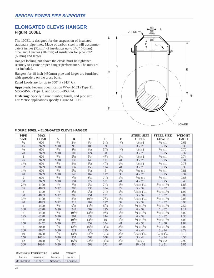
ELONGATED CLEVIS HANGERFigure 100EL
The 100EL is designed for the suspension of insulated stationary pipe lines. Made of carbon steel it will accommo-date 2 inches (51mm) of insulation up to 11/2" (40mm)pipe, and 4 inches (102mm) of insulation for pipe 21/2"(65mm) and larger.
Hanger locking nut above the clevis must be tightenedsecurely to assure proper hanger performance. The nuts arenot included.
Hangers for 18 inch (450mm) pipe and larger are furnishedwith spreaders on the cross bolts.
Rated Loads are for up to 650° F (343° C).
Approvals: Federal Specification WW-H-171 (Type 1),MSS-SP-69 (Type 1) and BSPSS-BS3974.
Ordering: Specify figure number, finish, and pipe size.For Metric applications specify Figure M100EL.
FIGURE 100EL – ELONGATED CLEVIS HANGER
PIPE MAX STEEL SIZE STEEL SIZE WEIGHTSIZE LOAD A B C E F UPPER LOWER EACH
1/2 600 3/8 33/4 41/4 31/2 5/8 1/8 x 1 1/8 x 1 0.6615 2669 M10 95 108 89 16 3 x 25 3 x 25 0.303/4 600 3/8 41/4 47/8 37/8 5/8 1/8 x 1 1/8 x 1 0.7020 2669 M10 108 124 98 16 3 x 25 3 x 25 0.321 600 3/8 51/8 53/4 43/4 15/8 1/8 x 1 1/8 x 1 0.7425 2669 M10 130 146 121 41 3 x 25 3 x 25 0.3411/4 600 3/8 53/8 61/8 47/8 15/8 1/8 x 1 1/8 x 1 0.7832 2669 M10 137 156 124 41 3 x 25 3 x 25 0.3511/2 600 3/8 51/2 63/8 5 11/2 5/32 x 1 1/8 x 1 0.8140 2669 M10 140 162 127 38 4 x 25 3 x 25 0.372 600 3/8 75/8 83/4 71/8 15/8 5/32 x 1 1/8 x 1 0.8850 2669 M10 194 222 181 41 4 x 25 3 x 25 0.4021/2 1100 1/2 77/8 91/4 71/4 11/8 3/16 x 11/4 3/16 x 11/4 1.8365 4893 M12 200 235 184 29 5 x 32 5 x 32 0.833 1100 1/2 81/8 97/8 71/2 11/8 3/16 x 11/4 3/16 x 11/4 1.9780 4893 M12 206 251 191 29 5 x 32 5 x 32 0.8931/2 1100 1/2 83/8 103/8 73/4 11/4 3/16 x 11/4 3/16 x 11/4 2.0690 4893 M12 213 264 197 32 5 x 32 5 x 32 0.934 1400 5/8 95/8 117/8 87/8 13/4 1/4 x 11/4 3/16 x 11/4 2.57
100 6228 M16 244 302 225 44 6 x 32 5 x 32 1.175 1400 5/8 103/8 131/8 95/8 17/8 1/4 x 11/4 3/16 x 11/4 3.00
125 6228 M16 264 333 244 48 6 x 32 5 x 32 1.366 1900 3/4 107/8 141/8 10 15/8 1/4 x 11/2 3/16 x 11/2 4.05
150 8452 M20 276 359 254 41 6 x 38 5 x 38 1.848 2000 7/8 125/8 167/8 115/8 21/8 1/4 x 13/4 3/16 x 13/4 6.00
200 8897 M20 321 429 295 54 6 x 44 5 x 44 2.7210 3600 7/8 131/4 185/8 121/8 23/8 3/16 x 13/4 1/4 x 13/4 10.10250 16014 M20 337 562 308 60 5 x 44 6 x 44 4.5812 3800 7/8 153/4 221/8 145/8 25/8 3/8 x 2 1/4 x 2 12.90300 16904 M20 400 562 371 67 10 x 51 6 x 51 5.85

INCHES FAHRENHEIT POUNDS POUNDS
MILLIMETERS CELSIUS NEWTONS KILOGRAMS
DIMENSIONS TEMPERATURE LOADS WEIGHT
23
BERGEN-POWER PIPE SUPPORTS
FS
KG
STOCKSIZE
F
B
C
E
C – C
CL
RISER CLAMPFigure 124
This product is designed to support vertical piping by resting on shear lugs welded to the pipe. Shear lugs are not supplied.
The stated Maximum Loads are based upon the use of theclamp as a rigid support. Use of the clamp with springsunits will double the given Maximum Loads. Rated loadsare for up to 650° F (343° C).
Material: Carbon Steel.
Ordering: Specify figure number, finish, and pipe size. For Metric applications specify Figure M124.
NOTE: For your Special Riser Clamp requirements that arenot covered by this product, please contact us to discussyour application.
FIGURE 124 – RISER CLAMPPIPE MAX WEIGHTSIZE LOAD A B C C-C E F G K S EACH
2 900 11/4 2 - 18 9 3/8 1/2 x 21/2 3/16 3/4 17.550 4004 32 51 - 457 229 M10 13 x 64 5 19 7.921/2 900 11/4 2 - 20 10 3/8 1/2 x 21/2 11/16 3/4 19.165 4004 32 51 - 508 254 M10 13 x 64 27 19 8.73 1500 11/2 2 - 20 10 1/2 5/8 x 3 13/8 3/4 29.480 6673 38 51 - 508 254 M12 16 x 76 35 19 13.34 2200 17/8 2 - 22 11 1/2 3/4 x 3 17/8 3/4 38.5
100 9786 48 51 - 559 279 M12 19 x 76 48 19 17.55 2200 3/4 2 - 22 11 1/2 5/8 x 4 23/8 3/4 43.2
125 9786 19 51 - 559 279 M12 16 x 102 60 19 19.66 3000 7/8 2 - 24 12 5/8 3/4 x 4 213/16 1 56.8
150 13345 22 51 - 610 305 M16 19 x 102 71 25 25.88 3000 7/8 2 - 27 131/2 5/8 3/4 x 5 313/16 1 79.2
200 13345 22 51 - 686 343 M16 19 x 127 97 25 35.910 5500 11/4 2 - 30 15 7/8 1 x 6 45/8 11/2 143.3250 24466 32 51 - 762 381 M20 25 x 152 117 38 65.012 7800 13/8 21/2 - 32 16 1 1 x 7 51/2 13/4 183.7300 34698 35 64 - 813 406 M24 25 x 178 140 44 83.314 7800 13/8 21/2 - 34 17 1 1 x 7 61/8 13/4 194.5350 34698 35 64 - 864 432 M24 25 x 178 156 44 88.216 9000 11/2 21/2 - 36 18 11/8 11/4 x 6 7 2 224.7400 40036 38 64 - 914 457 M30 32 x 152 178 51 101.918 9000 11/2 21/2 - 39 191/2 11/8 11/4 x 7 8 2 280.7450 40036 38 64 - 991 495 M30 32 x 178 203 51 127.320 13500 17/8 3 4 42 21 13/8 11/2 x 8 83/4 21/2 429.1500 60053 48 76 102 1067 533 M36 38 x 203 222 64 194.624 13500 17/8 3 4 45 221/2 13/8 11/2 x 8 103/4 21/2 465.1600 60053 48 76 102 1143 572 M36 38 x 203 273 64 211.0

INCHES FAHRENHEIT POUNDS POUNDS
MILLIMETERS CELSIUS NEWTONS KILOGRAMS
DIMENSIONS TEMPERATURE LOADS WEIGHT
24
BERGEN-POWER PIPE SUPPORTS
PIPE STANCHION WITH U-BOLTFigure 125
The Figure 125 is used for support of piping from belowwithout welding to the pipe.
Rated loads are for up to 650° F (343° C).
Material: Made from carbon steel, sizes 20 inch and larger are furnished with two U-bolts. The lower supporting pipe ‘A’ must be ordered separately.
Compliance: Federal Specification WW-H-171 (Type38), MSS-SP-69 (Type 37), and BSPSS-BS3974
Finish: Plain, Galvanized
Ordering: Specify figure number, finish, and pipe size. For Metric applications specify Figure M125.
FIGURE 125 – PIPE STANCHION WITH U-BOLT
MAXIMUM SUPPORT PIPE STEEL SIZE STEM WEIGHTPIPE SIZE LOAD A B C D EACH
4 1200 3 1/4 x4 1/2 21/2 5.15100 270 80 6 x10² M12 65 2.345 1200 3 1/4 x4 1/2 21/2 5.61
125 270 80 6 x10² M12 65 2.546 1200 3 3/8 x4 5/8 21/2 7.30
150 270 80 10 x102 M16 65 3.318 1200 3 3/8 x4 5/8 21/2 9.25
200 270 80 10 x102 M16 65 4.2010 1200 3 1/2 x4 3/4 21/2 13.75250 270 80 13 x102 M20 65 6.2412 1200 3 1/2 x4 7/8 21/2 15.50300 270 80 13 x102 M20 65 7.0314 1500 4 5/8 x5 7/8 3 25.35350 337 100 16 x127 M20 80 11.5016 1750 4 5/8 x5 7/8 3 30.80400 393 100 16 x127 M20 80 13.9718 2000 4 3/4 x5 1 3 37.64450 450 100 19 x127 M24 80 17.0720 3500 6 3/4 x8 (2)-1 5 75.35500 787 150 19 x203 (2)-M24 125 34.1824 3500 6 1 x8 (2)-11/8 5 112.80600 787 150 25 x203 (2)-M30 125 51.1730 3500 6 1 x8 (2)-11/8 5 137.30750 787 150 25 x203 (2)-M30 125 62.2836 3500 8 1 x10 (2)-11/4 6 210.15900 787 200 25 x250 (2)-M30 150 95.32
D
A
C
E
4"B
DOUBLE U-BOLTSFOR 20" AND LARGER
PIPE SIZES
CL

INCHES FAHRENHEIT POUNDS POUNDS
MILLIMETERS CELSIUS NEWTONS KILOGRAMS
DIMENSIONS TEMPERATURE LOADS WEIGHT
25
BERGEN-POWER PIPE SUPPORTS
PIPE MAX STEEL BOLT WGTSIZE LOAD A SIZE SIZE EACH
1/2 255 9 3/16 x 11/4 3/8 x 11/4 1.0015 1134 229 5 x 32 10 x 32 0.453/4 255 87/8 3/16 x 1 3/8 x 11/2 1.0820 1134 225 5 x 25 10 x 38 0.491 255 87/8 3/16 x 1 3/8 x 11/2 1.0825 1134 225 5 x 25 10 x 38 0.4911/4 255 10 3/16 x 1 3/8 x 11/2 1.8632 1134 254 5 x 25 10 x 38 0.8411/2 255 101/4 3/16 x 1 3/8 x 11/2 1.2240 1134 260 5 x 25 10 x 38 0.552 255 101/4 3/16 x 1 7/16 x 11/2 1.3050 1134 6613 5 x 25 11 x 38 0.5921/2 390 111/4 1/4 x 1 7/16 x 11/2 1.7465 1735 286 6 x 25 11 x 38 0.793 530 113/8 1/4 x 1 7/16 x 11/2 1.9880 2358 289 6 x 25 11 x 38 0.9031/2 670 127/8 1/4 x 1 1/2 x 2 2.1490 2980 327 6 x 25 13 x 51 0.974 810 127/8 1/4 x 1 1/2 x 2 2.28
100 3603 327 6 x 25 13 x 51 1.035 1160 133/4 1/4 x 11/2 1/2 x 2 3.60
125 5160 349 6 x 38 13 x 51 1.636 1570 143/4 1/4 x 11/2 1/2x 2 3.68
150 6984 375 6 x 38 13 x 51 1.678 2500 181/2 3/8 x 11/2 5/8 x 2 7.26
200 11121 470 10 x 38 16 x 51 3.2910 2500 203/4 3/8 x 2 5/8 x 21/2 11.00250 11121 527 10 x 51 16 x 64 4.9912 2700 223/4 1/2 x 2 5/8 x 21/2 15.94300 12011 578 13 x 51 16 x 64 7.2314 2700 24 1/2 x 2 5/8 x 3 17.36350 12011 610 13 x 51 16 x 76 7.8716 2900 26 5/8 x 21/2 3/4 x 3 29.68400 12900 660 16 x 64 19 x 76 13.4618 2900 28 5/8 x 21/2 3/4 x 3 31.64450 12900 711 16 x 64 19 x 76 14.3520 2900 30 5/8 x 21/2 3/4 x 31/2 34.84500 12900 762 16 x 64 19 x 89 15.8024 2900 34 5/8 x 3 11/8 x 4 50.00600 12900 864 16 x 76 29 x 102 22.68
CL
4" 4"
A
EXTENSION RISER CLAMPFigure 126
The Figure 126 is designed for the support or steadying of vertical pipe risers. It is made of carbon steel and isdesigned to hold tight to the pipe, transmitting the load tothe structure through the ears on each end. When possiblethe clamp should be placed under a coupling, hub, or lugswelded to the pipe.
NOTE: This product is not designed to be supported withrods. Use our Figure 124 when hanger rods are required.
Approvals: Federal Specification WW-H-171 (Type 8),MSS-SP-69 (Type 8) and BSPSS-BS3974.
Ordering: Specify figure number, finish, and pipe size. For Metric applications specify M126.
FIGURE 126 – EXTENSION RISER CLAMP

INCHES FAHRENHEIT POUNDS POUNDS
MILLIMETERS CELSIUS NEWTONS KILOGRAMS
DIMENSIONS TEMPERATURE LOADS WEIGHT
26
BERGEN-POWER PIPE SUPPORTS
C
E
D
K
A
F
CL
STANDARD ALLOY YOKE CLAMPFigure 134
The Figure 134 is recommended for the suspension of high temperature piping that requires up to 4 inches ofinsulation. Normally used with a Figure 93 Welded Eyerodor Figure 279 Weldless Eyenut. An alloy load distributionstrap is provided.
FIGURE 134 – STANDARD ALLOY YOKE CLAMP
MAXIMUM LOAD TAKEPIPE 750° F 950° F 1000° F 1050° F C D OUT F K WEIGHTSIZE 399° C 510° C 538° C 566° C E EACH
4 3780 3300 2770 1890 11/8 37/8 63/4 7/8 61/2 4.0100 16815 14680 12322 8407 29 98 171 M20 165 1.86 6060 5290 4440 3030 11/2 51/2 83/8 1 91/8 7.5
150 26957 23532 19751 13479 38 140 213 M24 232 3.48 6060 5290 4440 3030 11/2 63/4 95/8 1 111/8 9.0
200 26957 23532 19751 13479 38 171 244 M24 283 4.110 9060 7910 6640 4420 11/2 83/8 107/8 11/8 135/8 15.8250 40302 35187 29537 19662 38 213 276 M30 346 7.212 12570 10980 9015 6010 2 101/8 127/8 11/2 161/8 24.3300 55916 48843 40102 26735 51 257 327 M36 410 11.014 12570 10980 9015 6010 2 111/8 137/8 11/2 173/8 26.3350 55916 48843 40102 26735 51 283 352 M36 441 11.916 12570 10980 9015 6010 2 121/4 15 11/2 195/8 31.0400 55916 48843 40102 26735 51 311 381 M36 498 14.1
Material: Chrome molybdenum steel except U-bolt, whichis stainless steel.
Compliance: Federal Specification WW-H-171 (Type 2),MSS-SP-69 (Type 2), and BSPSS-BS3974.
Finish: Plain.
Ordering: Specify figure number, pipe size, and finish.For Metric applications specify Figure M134.

INCHES FAHRENHEIT POUNDS POUNDS
MILLIMETERS CELSIUS NEWTONS KILOGRAMS
DIMENSIONS TEMPERATURE LOADS WEIGHT
27
BERGEN-POWER PIPE SUPPORTS
ADJUSTABLE PIPE SUPPORTFigure 137
Designed to support pipe from below, the Figure 137 isused in conjunction with flange or base mounted pipe column “B”. The stem is threaded its full length and furnished with an nut to allow for vertical adjustment. A hardened flat washer (not furnished) should be installedunder the adjustment nut.
Rated Loads are for up to 650° F (343° C).
Material: Carbon Steel.
Finish: Plain, Electro-galvanized.
Ordering: Specify figure number, finish and pipe size. For Metric applications specify M137.
FIGURE 137 – ADJUSTABLE PIPE SUPPORT
STEELPIPE SIZE WEIGHTSIZE A B C EACH
1 5/8 8 1/4 x 11/4 0.7025 M16 203 6 x 32 0.3211/2 5/8 8 1/4 x 11/4 0.7440 M16 203 6 x 32 0.342 5/8 8 1/4 x 1 0.8050 M16 203 6 x 25 0.3621/2 5/8 8 1/4 x 1 0.8465 M16 203 6 x 25 0.383 5/8 8 1/4 x 1 1.0280 M16 203 6 x 25 0.4631/2 5/8 8 1/4 x 1 1.0690 M16 203 6 x 25 0.484 7/8 8 1/4 x 11/4 1.86
100 M20 203 6 x 32 0.845 7/8 8 1/4 x 11/4 2.50
125 M20 203 6 x 32 1.136 1 8 3/8 x 11/2 2.98
160 M24 203 10 x 38 1.358 1 8 3/8 x 11/2 3.28
200 M24 203 10 x 38 1.4910 11/4 8 1/2 x 2 6.30250 M30 203 13 x 51 2.8612 11/4 8 1/2 x 2 7.00300 M30 203 13 x 51 3.18
CL
C
A
8" FLAT WASHER(NOT FURNISHED)
SUPPORT PIPE "B"
INCHES FAHRENHEIT POUNDS POUNDS
MILLIMETERS CELSIUS NEWTONS KILOGRAMS
DIMENSIONS TEMPERATURE LOADS WEIGHT
28
BERGEN-POWER PIPE SUPPORTS
FC
DE
EDG
STOCKSIZE
CL
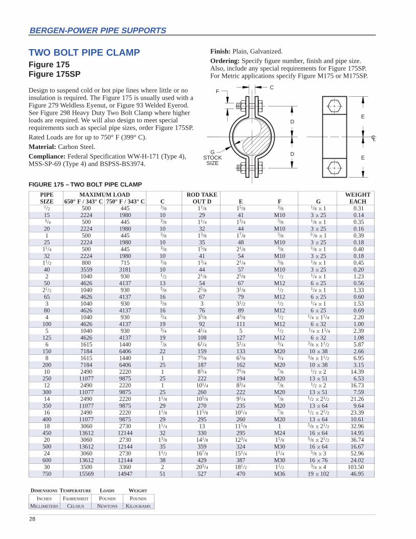
TWO BOLT PIPE CLAMPFigure 175Figure 175SP
Design to suspend cold or hot pipe lines where little or noinsulation is required. The Figure 175 is usually used with aFigure 279 Weldless Eyenut, or Figure 93 Welded Eyerod.See Figure 298 Heavy Duty Two Bolt Clamp where higherloads are required. We will also design to meet specialrequirements such as special pipe sizes, order Figure 175SP.
Rated Loads are for up to 750° F (399° C).
Material: Carbon Steel.
Compliance: Federal Specification WW-H-171 (Type 4),MSS-SP-69 (Type 4) and BSPSS-BS3974.
FIGURE 175 – TWO BOLT PIPE CLAMP
PIPE MAXIMUM LOAD ROD TAKE WEIGHTSIZE 650° F / 343° C 750° F / 343° C C OUT D E F G EACH
1/2 500 445 3/8 11/8 15/8 3/8 1/8 x 1 0.3115 2224 1980 10 29 41 M10 3x 25 0.143/4 500 445 3/8 11/4 13/4 3/8 1/8 x 1 0.3520 2224 1980 10 32 44 M10 3x 25 0.161 500 445 3/8 13/8 17/8 3/8 1//8 x 1 0.3925 2224 1980 10 35 48 M10 3x 25 0.1811/4 500 445 3/8 15/8 21/8 3/8 1/8 x 1 0.4032 2224 1980 10 41 54 M10 3x 25 0.1811/2 800 715 3/8 13/4 21/4 3/8 1/8 x 1 0.4540 3559 3181 10 44 57 M10 3x 25 0.202 1040 930 1/2 21/8 25/8 1/2 1/4 x 1 1.2350 4626 4137 13 54 67 M12 6x 25 0.5621/2 1040 930 5/8 25/8 31/8 1/2 1/4 x 1 1.3365 4626 4137 16 67 79 M12 6x 25 0.603 1040 930 5/8 3 31/2 1/2 1/4 x 1 1.5380 4626 4137 16 76 89 M12 6x 25 0.694 1040 930 3/4 35/8 43/8 1/2 1/4 x 11/4 2.20
100 4626 4137 19 92 111 M12 6x 32 1.005 1040 930 3/4 41/4 5 1/2 1/4 x 11/4 2.39
125 4626 4137 19 108 127 M12 6x 32 1.086 1615 1440 7/8 61/4 51/4 3/4 3/8 x 11/2 5.87
150 7184 6406 22 159 133 M20 10x 38 2.668 1615 1440 1 73/8 63/8 3/4 3/8 x 11/2 6.95
200 7184 6406 25 187 162 M20 10x 38 3.1510 2490 2220 1 83/4 75/8 7/8 1/2 x 2 14.39250 11077 9875 25 222 194 M20 13x 51 6.5312 2490 2220 1 101/4 83/4 7/8 1/2 x 2 16.73300 11077 9875 25 260 222 M20 13x 51 7.5914 2490 2220 11/8 105/8 91/4 7/8 1/2 x 21/2 21.26350 11077 9875 29 270 235 M20 13x 64 9.6416 2490 2220 11/8 115/8 101/4 7/8 1/2 x 21/2 23.39400 11077 9875 29 295 260 M20 13x 64 10.6118 3060 2730 11/4 13 115/8 1 5/8 x 21/2 32.96450 13612 12144 32 330 295 M24 16x 64 14.9520 3060 2730 13/8 141/8 123/4 11/8 5/8 x 21/2 36.74500 13612 12144 35 359 324 M30 16x 64 16.6724 3060 2730 11/2 167/8 151/4 11/4 5/8 x 3 52.96600 13612 12144 38 429 387 M30 16x 76 24.0230 3500 3360 2 203/4 181/2 11/2 3/4 x 4 103.50750 15569 14947 51 527 470 M36 19x 102 46.95
Finish: Plain, Galvanized.
Ordering: Specify figure number, finish and pipe size.Also, include any special requirements for Figure 175SP. For Metric applications specify Figure M175 or M175SP.

INCHES FAHRENHEIT POUNDS POUNDS
MILLIMETERS CELSIUS NEWTONS KILOGRAMS
DIMENSIONS TEMPERATURE LOADS WEIGHT
29
BERGEN-POWER PIPE SUPPORTS
D
E
8"
F
C
"B"
A
SUPPORT PIPE(NOT FURNISHED)
WASHER(NOT FURNISHED)
ADJUSTABLE PIPE STANCHIONWITH U-BOLTFigure 191
The Figure 191 is used for support of piping from belowwithout welding to the pipe with the added adjustment featureand a U-bolt for increased stability. The lower supporting pipe“B” must be ordered separately. A hardened flat washer (notfurnished) should be used under the adjusting nut.
Rated loads are for up to 650° F (343° C).
Material: Carbon Steel.
Compliance: Federal Specification WW-H-171 (Type 38),MSS-SP-69 (Type 37), and BSPSS-BS3974.
Finish: Plain, Electro-Galvanized.
Ordering: Specify figure number, finish, and pipe size. For Metric applications specify Figure M191.
FIGURE 191 – ADJUSTABLE PIPE STANCHION WITH U-BOLT
PIPE SUPPORT PIPE STEEL SIZE WEIGHTSIZE A B C D E F EACH
2 5/8 1 27/8 1/4 91/2 1/4 x 1 1.250 M16 25 73 6 241 6 x 25 0.521/2 5/8 1 33/8 3/8 93/4 1/4 x 1 1.465 M16 25 86 10 248 6 x 25 0.63 5/8 1 4 3/8 101/8 1/4 x 1 1.680 M16 25 102 10 257 6 x 25 0.731/2 5/8 1 5 3/8 103/8 1/4 x 1 2.690 M16 25 127 10 264 6 x 25 1.24 7/8 1 51/8 1/2 105/8 1/4 x 11/4 3.0
100 M20 25 130 13 270 6 x 32 1.45 7/8 1 61/8 1/2 111/8 1/4 x 11/4 3.2
125 M20 25 156 13 283 6 x 32 1.56 1 11/4 73/8 5/8 113/4 3/8 x 11/2 4.9
150 M24 32 187 16 298 10 x 38 2.28 1 11/4 93/8 5/8 123/4 3/8 x 11/2 6.2
200 M24 32 238 16 324 10 x 38 2.810 11/4 11/2 115/8 5/8 14 1/2 x 2 10.5250 M30 38 295 16 356 13 x 51 4.812 11/4 11/2 133/4 5/8 15 1/2 x 2 11.8300 M30 38 349 16 381 13 x 51 5.4

INCHES FAHRENHEIT POUNDS POUNDS
MILLIMETERS CELSIUS NEWTONS KILOGRAMS
DIMENSIONS TEMPERATURE LOADS WEIGHT
30
BERGEN-POWER PIPE SUPPORTS
1/16Pv
A
T
W
1/16Pv
A
C – C
X
T
W BOLT ø + 1/16"
FIGURE 242A FIGURE 242B
PIPE STRAPSFigure 242A, 242B
The Figure 242 is designed to restrain piping laterally whilepermitting movement in the axial and vertical direction. Fig 242A is a welded design and Figure 242B is bolted.Larger sizes are available upon request.
Rated loads are for up to 650° F (343° C).
FIGURE 242A, 242B – PIPE STRAPS
MAX WEIGHTPIPE LOAD BOLT A B C E F G EACHSIZE PL SIZE 242A 242B
1/2 125 3/4 1 2 4 3 1/4 3 1.06 1.7715 556 M20 25 51 102 76 6 76 0.48 0.803/4 125 3/4 13/16 2 43/16 3 1/4 3 1.09 1.8020 556 M20 30 51 106 76 6 76 0.49 0.821 125 3/4 17/16 2 47/16 31/4 1/4 3 1.20 1.9025 556 M20 37 51 113 83 6 76 0.54 0.8611/4 300 3/4 13/4 3 43/4 31/2 3/8 3 3.03 4.4632 1335 M20 44 76 121 89 10 76 1.37 2.0211/2 300 3/4 2 3 5 4 3/8 3 3.43 4.8640 1335 M20 51 76 127 102 10 76 1.55 2.202 300 3/4 21/2 3 51/2 41/2 3/8 3 3.90 5.3450 1335 M20 64 76 140 114 10 76 1.77 2.4221/2 450 7/8 3 3 63/4 5 1/2 33/4 5.95 8.2965 2002 M20 76 76 171 127 13 95 2.70 3.763 450 7/8 39/16 4 75/16 51/2 1/2 33/4 8.82 11.9380 2002 M20 90 102 186 140 13 95 4.00 5.414 450 7/8 49/16 4 85/16 61/2 1/2 33/4 10.52 13.63
100 2002 M20 116 102 211 165 13 95 4.77 6.186 500 7/8 6 3/4 6 101/2 81/2 1/2 33/4 21.04 25.71
M48 2224 M20 171 152 267 216 13 95 9.54 11.66
Material: Carbon Steel.
Finish: Plain.
Ordering: Specify figure number, and pipe size.For Metric applications, specify Figure M242A or M242B.
INCHES FAHRENHEIT POUNDS POUNDS
MILLIMETERS CELSIUS NEWTONS KILOGRAMS
DIMENSIONS TEMPERATURE LOADS WEIGHT
31
BERGEN-POWER PIPE SUPPORTS
1/16Pv
A
C – C
T
X
W BOLT ø + 1/16"
1/16Pv
TA
W
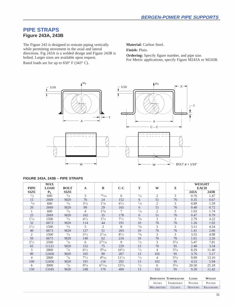
Material: Carbon Steel.
Finish: Plain.
Ordering: Specify figure number, and pipe size.For Metric applications, specify Figure M243A or M243B.
FIGURE 243A, 243B – PIPE STRAPS
MAX WEIGHTPIPE LOAD BOLT A B C-C T W X EACHSIZE PL SIZE 243A 243B
1/2 600 3/4 3 15/16 6 1/4 2 3 0.76 1.4715 2669 M20 76 24 152 6 51 76 0.35 0.673/4 600 3/4 31/2 11/8 61/2 1/4 2 3 0.89 1.5920 2669 M20 89 29 165 6 51 76 0.40 0.721 600 3/4 4 13/8 7 1/4 2 3 1.03 1.7425 2669 M20 102 35 178 6 51 76 0.47 0.7911/4 1500 3/4 41/2 13/4 71/2 3/8 3 3 2.79 4.2232 6673 M20 114 44 191 10 76 76 1.26 1.9211/2 1500 3/4 5 2 8 3/8 3 3 3.11 4.5440 6673 M20 127 51 203 10 76 76 1.41 2.062 1500 3/4 51/2 27/16 81/2 3/8 3 3 3.55 4.9850 6673 M20 140 62 216 10 76 76 1.61 2.2621/2 2500 7/8 6 215/16 9 1/2 3 33/4 5.47 7.8165 11121 M20 152 75 229 13 76 95 2.48 3.543 2800 7/8 61/2 39/16 101/2 1/2 4 33/4 8.29 11.4080 12456 M20 165 90 267 13 102 95 3.76 5.174 2800 7/8 71/2 49/16 111/2 1/2 4 33/4 9.99 13.10
100 12456 M20 191 116 292 13 102 95 4.53 5.946 3000 7/8 93/4 611/16 153/4 1/2 6 33/4 20.50 25.18
150 13345 M20 248 170 400 13 152 95 9.30 11.42
PIPE STRAPSFigure 243A, 243B
The Figure 243 is designed to restrain piping verticallywhile permitting movement in the axial and lateral directions. Fig 243A is a welded design and Figure 243B isbolted. Larger sizes are available upon request.
Rated loads are for up to 650° F (343° C).
INCHES FAHRENHEIT POUNDS POUNDS
MILLIMETERS CELSIUS NEWTONS KILOGRAMS
DIMENSIONS TEMPERATURE LOADS WEIGHT
32
BERGEN-POWER PIPE SUPPORTS
PLPL
Pv
A
T
1/16
W
X 1/16
Pv
TA
C – C
PL PL
W BOLT ø + 1/16"
FIGURE 244A FIGURE 244B
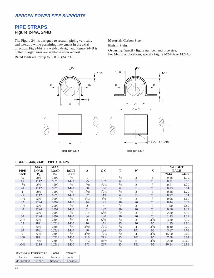
PIPE STRAPSFigure 244A, 244B
The Figure 244 is designed to restrain piping vertically and laterally while permitting movement in the axial direction. Fig 244A is a welded design and Figure 244B isbolted. Larger sizes are available upon request.
Rated loads are for up to 650° F (343° C).
FIGURE 244A, 244B – PIPE STRAPS
MAX MAX WEIGHTPIPE LOAD LOAD BOLT A C-C T W X EACHSIZE PL PV SIZE 244A 244B
1/2 250 1500 3/4 1 4 1/4 2 3 0.46 1.1015 1112 6673 M20 25 102 6 51 76 0.21 0.503/4 250 1500 3/4 13/16 43/16 1/4 2 3 0.51 1.2020 1112 6673 M20 30 106 6 51 76 0.23 0.541 250 1500 3/4 17/16 47/16 1/4 2 3 0.58 1.2025 1112 6673 M20 37 113 6 51 76 0.27 0.5411/4 500 2000 3/4 13/4 43/4 3/8 3 3 0.96 1.6032 2224 8897 M20 44 121 10 76 76 0.44 0.7311/2 500 2000 3/4 2 5 3/8 3 3 1.90 2.8040 2224 8897 M20 51 127 10 76 76 0.86 1.272 500 2000 3/4 21/2 51/2 3/8 3 3 2.50 3.9050 2224 8897 M20 64 140 10 76 76 1.13 1.7721/2 650 2300 7/8 3 63/4 1/2 3 33/4 4.30 6.3065 2891 10231 M20 76 171 13 76 95 1.95 2.863 650 2300 7/8 39/16 75/16 1/2 4 33/4 8.10 10.2080 2891 10231 M20 90 186 13 102 95 3.67 4.634 650 2300 7/8 49/16 85/16 1/2 4 33/4 15.60 19.00
100 2891 10231 M20 116 211 13 102 95 7.08 8.626 700 2300 7/8 63/4 101/2 1/2 6 33/4 22.80 30.60
M48 3114 10231 M20 171 267 13 152 95 10.34 13.88
Material: Carbon Steel.
Finish: Plain.
Ordering: Specify figure number, and pipe size.For Metric applications, specify Figure M244A or M244B.
INCHES FAHRENHEIT POUNDS POUNDS
MILLIMETERS CELSIUS NEWTONS KILOGRAMS
DIMENSIONS TEMPERATURE LOADS WEIGHT
33
BERGEN-POWER PIPE SUPPORTS
C
E
D
K
A
F
CL
3"
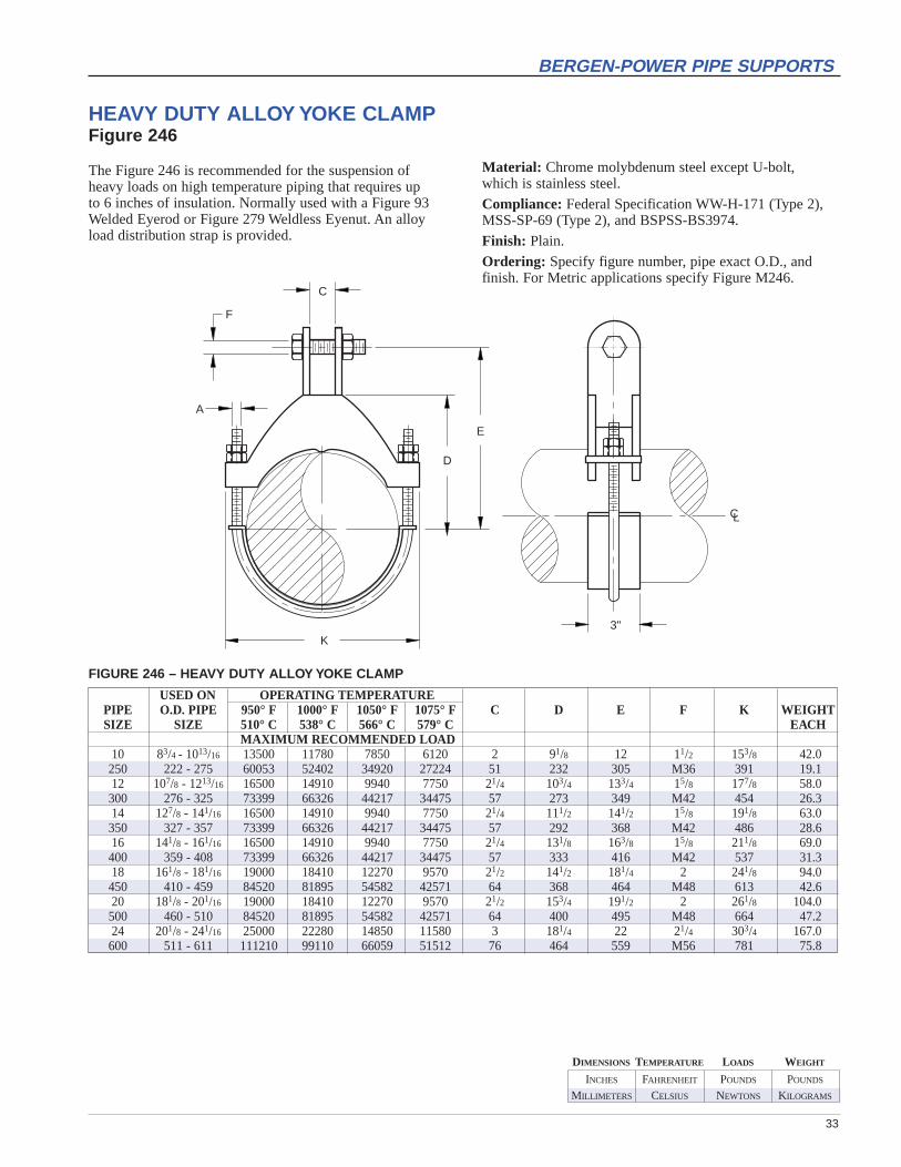
HEAVY DUTY ALLOY YOKE CLAMPFigure 246
The Figure 246 is recommended for the suspension ofheavy loads on high temperature piping that requires up to 6 inches of insulation. Normally used with a Figure 93Welded Eyerod or Figure 279 Weldless Eyenut. An alloyload distribution strap is provided.
FIGURE 246 – HEAVY DUTY ALLOY YOKE CLAMP
USED ON OPERATING TEMPERATUREPIPE O.D. PIPE 950° F 1000° F 1050° F 1075° F C D E F K WEIGHTSIZE SIZE 510° C 538° C 566° C 579° C EACH
MAXIMUM RECOMMENDED LOAD10 83/4 - 1013/16 13500 11780 7850 6120 2 91/8 12 11/2 153/8 42.0250 222 - 275 60053 52402 34920 27224 51 232 305 M36 391 19.112 107/8 - 1213/16 16500 14910 9940 7750 21/4 103/4 133/4 15/8 177/8 58.0300 276 - 325 73399 66326 44217 34475 57 273 349 M42 454 26.314 127/8 - 141/16 16500 14910 9940 7750 21/4 111/2 141/2 15/8 191/8 63.0350 327 - 357 73399 66326 44217 34475 57 292 368 M42 486 28.616 141/8 - 161/16 16500 14910 9940 7750 21/4 131/8 163/8 15/8 211/8 69.0400 359 - 408 73399 66326 44217 34475 57 333 416 M42 537 31.318 161/8 - 181/16 19000 18410 12270 9570 21/2 141/2 181/4 2 241/8 94.0450 410 - 459 84520 81895 54582 42571 64 368 464 M48 613 42.620 181/8 - 201/16 19000 18410 12270 9570 21/2 153/4 191/2 2 261/8 104.0500 460 - 510 84520 81895 54582 42571 64 400 495 M48 664 47.224 201/8 - 241/16 25000 22280 14850 11580 3 181/4 22 21/4 303/4 167.0600 511 - 611 111210 99110 66059 51512 76 464 559 M56 781 75.8
Material: Chrome molybdenum steel except U-bolt,which is stainless steel.
Compliance: Federal Specification WW-H-171 (Type 2),MSS-SP-69 (Type 2), and BSPSS-BS3974.
Finish: Plain.
Ordering: Specify figure number, pipe exact O.D., and finish. For Metric applications specify Figure M246.
34
BERGEN-POWER PIPE SUPPORTS
CL CL
D
E
C
B A
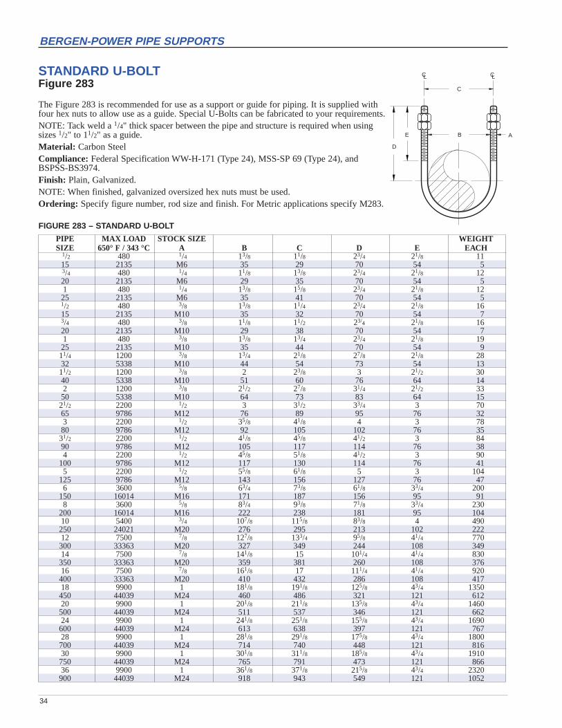
STANDARD U-BOLTFigure 283
The Figure 283 is recommended for use as a support or guide for piping. It is supplied withfour hex nuts to allow use as a guide. Special U-Bolts can be fabricated to your requirements.NOTE: Tack weld a 1/4" thick spacer between the pipe and structure is required when usingsizes 1/2" to 11/2" as a guide.Material: Carbon SteelCompliance: Federal Specification WW-H-171 (Type 24), MSS-SP 69 (Type 24), andBSPSS-BS3974.Finish: Plain, Galvanized.NOTE: When finished, galvanized oversized hex nuts must be used.Ordering: Specify figure number, rod size and finish. For Metric applications specify M283.
FIGURE 283 – STANDARD U-BOLT
PIPE MAX LOAD STOCK SIZE WEIGHTSIZE 650° F / 343 °C A B C D E EACH
1/2 480 1/4 13/8 11/8 23/4 21/8 1115 2135 M6 35 29 70 54 53/4 480 1/4 11/8 13/8 23/4 21/8 1220 2135 M6 29 35 70 54 51 480 1/4 13/8 15/8 23/4 21/8 1225 2135 M6 35 41 70 54 51/2 480 3/8 13/8 11/4 23/4 21/8 1615 2135 M10 35 32 70 54 73/4 480 3/8 11/8 11/2 23/4 21/8 1620 2135 M10 29 38 70 54 71 480 3/8 13/8 13/4 23/4 21/8 1925 2135 M10 35 44 70 54 911/4 1200 3/8 13/4 21/8 27/8 21/8 2832 5338 M10 44 54 73 54 1311/2 1200 3/8 2 23/8 3 21/2 3040 5338 M10 51 60 76 64 142 1200 3/8 21/2 27/8 31/4 21/2 3350 5338 M10 64 73 83 64 1521/2 2200 1/2 3 31/2 33/4 3 7065 9786 M12 76 89 95 76 323 2200 1/2 35/8 41/8 4 3 7880 9786 M12 92 105 102 76 3531/2 2200 1/2 41/8 45/8 41/2 3 8490 9786 M12 105 117 114 76 384 2200 1/2 45/8 51/8 41/2 3 90
100 9786 M12 117 130 114 76 415 2200 1/2 55/8 61/8 5 3 104
125 9786 M12 143 156 127 76 476 3600 5/8 63/4 73/8 61/8 33/4 200
150 16014 M16 171 187 156 95 918 3600 5/8 83/4 93/8 71/8 33/4 230
200 16014 M16 222 238 181 95 10410 5400 3/4 107/8 115/8 83/8 4 490250 24021 M20 276 295 213 102 22212 7500 7/8 127/8 133/4 95/8 41/4 770300 33363 M20 327 349 244 108 34914 7500 7/8 141/8 15 101/4 41/4 830350 33363 M20 359 381 260 108 37616 7500 7/8 161/8 17 111/4 41/4 920400 33363 M20 410 432 286 108 41718 9900 1 181/8 191/8 125/8 43/4 1350450 44039 M24 460 486 321 121 61220 9900 1 201/8 211/8 135/8 43/4 1460500 44039 M24 511 537 346 121 66224 9900 1 241/8 251/8 155/8 43/4 1690600 44039 M24 613 638 397 121 76728 9900 1 281/8 291/8 175/8 43/4 1800700 44039 M24 714 740 448 121 81630 9900 1 301/8 311/8 185/8 43/4 1910750 44039 M24 765 791 473 121 86636 9900 1 361/8 371/8 215/8 43/4 2320900 44039 M24 918 943 549 121 1052

INCHES FAHRENHEIT POUNDS POUNDS
MILLIMETERS CELSIUS NEWTONS KILOGRAMS
DIMENSIONS TEMPERATURE LOADS WEIGHT
35
BERGEN-POWER PIPE SUPPORTS
C
F
GSTOCK
SIZE
B
ED
H
HEAVY DUTY TWO BOLT PIPE CLAMPFigure 298
Design to suspend heavy loads on cold or hot pipe lineswhere little or no insulation is required. The Figure 298 isusually used with a Figure 279 Weldless Eyenut or Figure93 Welded Eyerod.
Rated Loads are for up to 750° F (399° C).
Material: Carbon Steel.
Compliance: Federal Specification WW-H-171 (Type 4),MSS-SP-69 (Type 4) and BSPSS-BS3974.
Finish: Plain, Galvanized.
Ordering: Specify figure number, finish and pipe size.For Metric applications specify Figure M298.
FIGURE 298 – HEAVY DUTY TWO BOLT PIPE CLAMP
MAX LOAD STOCKPIPE 650° F 750° F B C D E F SIZE H WGTSIZE 343° C 399° C G EACH
2 3400 3000 2 3/4 3 2 5/8 1/4 x 11/2 3 2.150 15125 13345 51 19 76 51 M16 6 x 38 76 1.03 3550 3150 31/8 1 4 31/8 3/4 1/4 x 2 4 3.880 15792 14012 79 25 102 79 M20 6 x 51 102 1.74 3550 3150 33/4 1 47/8 33/4 7/8 3/8 x 2 47/8 6.5
100 15792 14012 95 25 124 95 M20 10 x 51 124 2.95 3550 3150 43/8 1 51/2 43/8 7/8 3/8 x 2 51/2 7.4
125 15792 14012 111 25 140 111 M20 10 x 51 140 3.46 4900 4350 53/8 11/8 63/4 53/8 1 1/2 x 21/2 63/4 14.0
150 21797 19351 137 29 171 137 M24 13 x 64 171 6.48 4900 4350 63/4 11/8 81/8 63/4 1 1/2 x 21/2 81/8 16.4
200 21797 19351 171 29 206 171 M24 13 x 64 206 7.410 6000 5400 75/8 11/4 91/8 73/4 11/4 5/8 x 21/2 9 25.3250 26690 24021 194 32 232 197 M30 16 x 64 229 11.512 8700 7750 91/4 15/8 113/8 91/2 11/2 3/4 x 3 111/8 44.1300 38701 34475 235 41 289 241 M36 19 x 76 283 20.014 9150 8150 93/4 15/8 117/8 10 11/2 3/4 x 4 115/8 58.8350 40703 36254 248 41 302 254 M36 19 x 102 295 26.716 9150 8150 11 15/8 127/8 11 11/2 3/4 x 4 127/8 64.1400 40703 36254 279 41 327 279 M36 19 x 102 327 29.118 13800 12280 141/2 3 171/4 141/2 2 3/4 x 6 171/4 126.3450 61388 54626 368 76 438 368 M48 19 x 152 438 57.320 15300 13620 16 3 183/4 16 2 1 x 5 183/4 150.0500 68060 60587 406 76 476 406 M48 25 x 127 476 68.024 16300 14500 181/2 31/4 211/2 181/2 21/4 1 x 6 211/2 210.5600 72509 64502 470 83 546 470 M56 25 x 152 546 95.530 20500 18250 221/2 31/2 26 221/2 21/2 11/4 x 7 26 365.4750 91192 81183 572 89 660 572 M64 32 x 178 660 165.736 28000 24900 261/2 31/2 301/4 261/2 23/4 11/2 x 8 301/4 575.1900 124555 110765 673 89 768 673 M72 38 x 203 768 260.9

36
BERGEN-POWER PIPE SUPPORTS
MAXIMUM LOAD TAKEPIPE 650° F 750° F B C D OUT F G H WGTSIZE 343° C 399° C E EACH
1/2 950 845 1 5/8 27/8 21/4 3/8 3/16 x 1 15/8 0.6115 4226 3759 25 16 73 57 M10 5 x 25 41 0.283/4 950 845 11/8 5/8 31/4 21/2 3/8 3/16 x 1 13/4 0.6620 4226 3759 29 16 83 64 M10 5 x 25 44 0.301 950 845 11/2 5/8 33/4 21/2 3/8 3/16 x 1 21/8 0.6925 4226 3759 38 16 95 64 M10 5 x 25 54 0.3111/4 950 845 11/2 3/4 35/8 27/8 3/8 3/16 x 1 21/4 0.7532 4226 3759 38 19 92 73 M10 5 x 25 57 0.3411/2 1545 1380 13/4 1 47/8 41/8 5/8 1/4 x 11/4 23/8 2.1440 6873 6139 44 25 124 105 M16 6 x 32 60 0.972 1545 1380 21/8 11/8 57/8 51/8 5/8 1/4 x 11/4 23/4 2.4350 6873 6139 54 29 149 130 M16 6 x 32 70 1.1021/2 1545 1380 3 11/8 61/8 53/8 5/8 1/4 x 11/2 3 2.9265 6873 6139 76 29 156 137 M16 6 x 38 76 1.323 1545 1380 27/8 11/8 65/8 6 5/8 1/4 x 11/2 33/8 3.1980 6873 6139 73 29 168 152 M16 6 x 38 86 1.454 2500 2230 31/2 1 75/8 61/2 3/4 3/8 x 2 45/8 7.12
100 11121 9920 89 25 194 165 M20 10 x 51 117 3.235 2500 2230 4 11/8 81/8 7 3/4 3/8 x 2 51/8 7.96
125 11121 9920 102 29 206 178 M20 10 x 51 130 3.616 2865 2555 43/4 11/4 95/8 81/4 7/8 3/8 x 21/2 61/8 11.85
150 12745 11366 121 32 244 210 M20 10 x 64 156 5.388 2865 2555 53/4 11/4 105/8 91/4 7/8 3/8 x 21/2 71/8 13.59
200 12745 11366 146 32 270 235 M20 10 x 64 181 6.1610 3240 2890 67/8 11/4 12 101/2 1 1/2 x 21/2 81/4 21.33250 14413 12856 175 32 305 267 M24 13 x 64 210 9.6812 3240 2890 83/8 11/2 13 111/2 1 1/2 x 21/2 97/8 23.65300 14413 12856 213 38 330 292 M24 13 x 64 251 10.7314 4300 3835 91/8 2 143/8 123/4 11/4 5/8 x 3 103/4 38.78350 19128 17060 232 51 365 324 M30 16 x 76 273 17.5916 4300 3835 11 2 155/8 14 11/4 5/8 x 3 12 42.89400 19128 17060 279 51 397 356 M30 16 x 76 305 19.4518 4300 3835 115/8 2 163/4 151/8 11/4 5/8 x 3 131/4 46.35450 19128 17060 295 51 425 384 M30 16 x 76 337 21.0220 4500 4015 123/8 2 171/2 157/8 13/8 3/4 x 3 14 58.67500 20018 17860 314 51 445 403 M36 19 x 76 356 26.6124 5490 4900 143/4 2 197/8 177/8 11/2 3/4 x 4 163/8 89.32600 24422 21797 375 51 505 454 M36 19 x 102 416 40.5230 7500 6690 181/2 11/2 263/8 233/8 11/2 3/4 x 5 21 140.89750 33363 29760 470 38 670 594 M36 19 x 127 533 63.9136 10500 9360 221/2 3 321/8 283/4 13/4 1 x 5 26 246.44900 46708 41637 572 76 816 730 M42 25 x 127 660 111.79
FIGURE 304 – THREE BOLT PIPE CLAMP
FC
E
BGSTOCK
SIZE
CL
H
D
THREE BOLT PIPE CLAMPFigure 304
The Figure 304 is designed for hot insulated pipe lines up to 750° F. Thespacer on the top inner bolt provides uniform space for the connectingeyerod or weldless eyenut. See Figure 91 for higher load ratings. We willalso, design to meet special requirements such as special pipe sizes, orderFigure 304SP.
Rated Loads are for up to 750° F (399° C).
Material: Carbon Steel.
Compliance: Federal Specification WW-H-171 (Type 3), MSS-SP-69(Type 3) and BSPSS-BS3974.
Finish: Plain.
Ordering: Specify figure number, and pipe size. Also, include any specialrequirements for Figure 304SP. For Metric applications specify FigureM304 or M304SP.
INCHES FAHRENHEIT POUNDS POUNDS
MILLIMETERS CELSIUS NEWTONS KILOGRAMS
DIMENSIONS TEMPERATURE LOADS WEIGHT
37
BERGEN-POWER PIPE SUPPORTS
FC
E
BGSTOCK
SIZE
CL
D
H
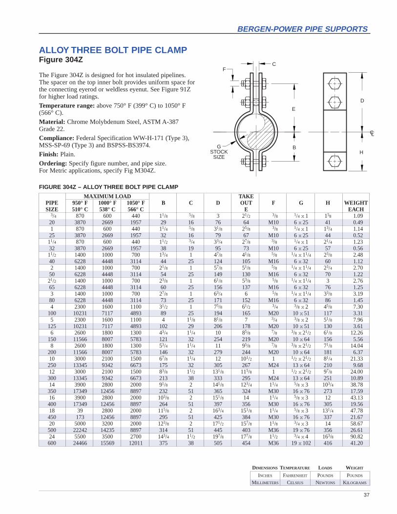
ALLOY THREE BOLT PIPE CLAMPFigure 304Z
The Figure 304Z is designed for hot insulated pipelines.The spacer on the top inner bolt provides uniform space forthe connecting eyerod or weldless eyenut. See Figure 91Zfor higher load ratings.
Temperature range:above 750° F (399° C) to 1050° F(566° C).
Material: Chrome Molybdenum Steel, ASTM A-387 Grade 22.
Compliance: Federal Specification WW-H-171 (Type 3),MSS-SP-69 (Type 3) and BSPSS-BS3974.
Finish: Plain.
Ordering: Specify figure number, and pipe size.For Metric applications, specify Fig M304Z.
FIGURE 304Z – ALLOY THREE BOLT PIPE CLAMP
MAXIMUM LOAD TAKEPIPE 950° F 1000° F 1050° F B C D OUT F G H WEIGHTSIZE 510° C 538° C 566° C E EACH
3/4 870 600 440 11/8 5/8 3 21/2 3/8 1/4 x 1 158 1.0920 3870 2669 1957 29 16 76 64 M10 6 x 25 41 0.491 870 600 440 11/4 5/8 31/8 25/8 3/8 1/4 x 1 13/4 1.1425 3870 2669 1957 32 16 79 67 M10 6 x 25 44 0.5211/4 870 600 440 11/2 3/4 33/4 27/8 3/8 1/4 x 1 21/4 1.2332 3870 2669 1957 38 19 95 73 M10 6 x 25 57 0.5611/2 1400 1000 700 13/4 1 47/8 41/8 5/8 1/4 x 11/4 23/8 2.4840 6228 4448 3114 44 25 124 105 M16 6 x 32 60 1.122 1400 1000 700 21/8 1 57/8 51/8 5/8 1/4 x 11/4 23/4 2.7050 6228 4448 3114 54 25 149 130 M16 6 x 32 70 1.2221/2 1400 1000 700 23/8 1 61/8 53/8 5/8 1/4 x 11/4 3 2.7665 6228 4448 3114 60 25 156 137 M16 6 x 32 76 1.253 1400 1000 700 27/8 1 63/4 6 5/8 1/4 x 11/4 33/8 3.1980 6228 4448 3114 73 25 171 152 M16 6 x 32 86 1.454 2300 1600 1100 31/2 1 75/8 61/2 3/4 3/8 x 2 45/8 7.30
100 10231 7117 4893 89 25 194 165 M20 10 x 51 117 3.315 2300 1600 1100 4 11/8 81/8 7 3/4 3/8 x 2 51/8 7.96
125 10231 7117 4893 102 29 206 178 M20 10 x 51 130 3.616 2600 1800 1300 43/4 11/4 10 85/8 7/8 3/8 x 21/2 61/8 12.26
150 11566 8007 5783 121 32 254 219 M20 10 x 64 156 5.568 2600 1800 1300 53/4 11/4 11 95/8 7/8 3/8 x 21/2 71/8 14.04
200 11566 8007 5783 146 32 279 244 M20 10 x 64 181 6.3710 3000 2100 1500 67/8 11/4 12 101/2 1 1/2 x 21/2 81/4 21.33250 13345 9342 6673 175 32 305 267 M24 13 x 64 210 9.6812 3000 2100 1500 83/8 11/2 131/8 115/8 1 1/2 x 21/2 97/8 24.00300 13345 9342 6673 213 38 333 295 M24 13 x 64 251 10.8914 3900 2800 2000 91/8 2 141/8 123/4 11/4 5/8 x 3 103/4 38.78350 17349 12456 8897 232 51 365 324 M30 16 x 76 273 17.5916 3900 2800 2000 103/8 2 151/8 14 11/4 5/8 x 3 12 43.13400 17349 12456 8897 264 51 397 356 M30 16 x 76 305 19.5618 39 2800 2000 115/8 2 163/4 151/8 11/4 5/8 x 3 131/4 47.78450 173 12456 8897 295 51 425 384 M30 16 x 76 337 21.6720 5000 3200 2000 123/8 2 171/2 157/8 11/8 3/4 x 3 14 58.67500 22242 14235 8897 314 51 445 403 M36 19 x 76 356 26.6124 5500 3500 2700 143/4 11/2 197/8 177/8 11/2 3/4 x 4 163/8 90.82600 24466 15569 12011 375 38 505 454 M36 19 x 102 416 41.20
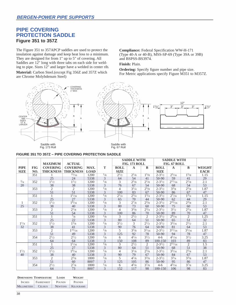
INCHES FAHRENHEIT POUNDS POUNDS
MILLIMETERS CELSIUS NEWTONS KILOGRAMS
DIMENSIONS TEMPERATURE LOADS WEIGHT
38
BERGEN-POWER PIPE SUPPORTS
12"3" 3" 3"11/2" 11/2"��
������
��������yyyyzzzz
{{{{||||
CENTER RIB
SIZES 12" &
LARGER
CL
B
COVERING THICKNESS 1" MAX
A
��������
��������yyyyzzzz
{{{{|||| B
A
Saddle withFig. 67 Roll
Saddle withFig. 173 Roll
PIPE COVERING PROTECTION SADDLEFigure 351 to 357Z
The Figure 351 to 357APCP saddles are used to protect theinsulation against damage and keep heat loss to a minimum.They are designed for from 1" up to 5" of covering. AllSaddles are 12" long with three tabs on each side for weld-ing to pipe. Sizes 12" and larger have a welded in center rib.
Material: Carbon Steel.(except Fig 356Z and 357Z whichare Chrome Molybdenum Steel)
Compliance: Federal Specification WW-H-171 (Type 40-A or 40-B), MSS-SP-69 (Type 39A or 39B) and BSPSS-BS3974.
Finish: Plain.
Ordering: Specify figure number and pipe size. For Metric applications specify Figure M351 to M357Z.
SADDLE WITH SADDLE WITHMAXIMUM ACTUAL FIG. 173 ROLL FIG. 67 ROLL
PIPE FIG COVERING COVERING MAX. T ROLL A B ROLL A B WEIGHTSIZE NO. THICKNESS THICKNESS LOAD SIZE SIZE EACH
351 1 15/16 1200 1/8 21/2 21/8 15/8 2-31/2 25/16 15/8 1.1525 24 5338 3 64 54 41 50-90 59 41 29
3/4 352 11/2 11/2 1200 1/8 3 25/8 21/8 2-31/2 211/16 21/8 2.120 38 38 5338 3 76 67 54 50-90 68 54 53
353 2 2 1200 1/8 4 31/4 25/8 2-31/2 33/8 25/8 1.8751 51 5338 3 100 83 67 50-90 86 67 47
351 1 11/16 1200 1/8 21/4 23/4 13/4 2-31/2 27/16 13/4 1.1525 27 5338 3 65 70 44 50-90 62 44 29
1 352 11/2 19/16 1200 1/8 3 27/8 23/8 2-31/2 215/16 23/8 2.125 38 40 5338 3 80 73 60 50-90 75 60 53
353 2 21/8 1200 1/8 4 33/8 23/4 2-31/2 31/2 23/4 1.8751 54 5338 3 100 86 70 50-90 89 70 47
351 1 7/8 1200 1/8 3 21/2 2 2-31/2 29/16 2 1.2525 22 5338 3 80 64 51 50-90 65 51 32
11/4 352 11/2 15/8 1200 1/8 31/2 3 21/2 2-31/2 33/16 21/2 2.132 38 41 5338 3 90 76 64 50-90 81 64 53
353 2 115/16 1200 1/8 5 35/8 31/16 2-31/2 311/16 31/16 1.8751 49 5338 3 125 92 78 50-90 94 78 47
354 21/2 21/2 1200 1/8 6 41/4 31/2 4-6 41/16 31/2 3.2564 64 5338 3 150 108 89 100-150 103 89 83
351 1 11/16 1200 1/8 3 21/2 2 2-31/2 211/16 2 1.525 27 5338 3 80 64 51 50-90 68 51 38
11/2 352 11/2 19/16 1200 1/8 4 31/8 25/8 2-31/2 35/16 25/8 2.140 38 40 5338 3 90 79 67 50-90 84 67 53
353 2 23/8 1800 1/8 5 41/8 33/8 2-31/2 33/4 33/8 1.8751 60 8007 3 125 105 86 50-90 95 86 47
354 21/2 27/8 1800 1/8 6 45/8 37/8 4-6 43/16 37/8 3.2564 73 8007 3 152 117 98 100-150 106 98 83
FIGURE 351 TO 357Z – PIPE COVERING PROTECTION SADDLE

INCHES FAHRENHEIT POUNDS POUNDS
MILLIMETERS CELSIUS NEWTONS KILOGRAMS
DIMENSIONS TEMPERATURE LOADS WEIGHT
39
BERGEN-POWER PIPE SUPPORTS
SADDLE WITH SADDLE WITHMAXIMUM ACTUAL FIG. 173 ROLL FIG. 67 ROLL
PIPE FIG COVERING COVERING MAX. T ROLL A B ROLL A B WEIGHTSIZE NO. THICKNESS THICKNESS LOAD SIZE SIZE EACH
351 1 11/16 1200 1/8 31/2 27/8 23/8 2-31/2 215/16 23/8 1.6325 27 5338 3 80 73 60 50-90 75 60 41
352 11/2 19/16 1200 1/8 4 31/8 25/8 2-31/2 35/16 25/8 2.138 40 5338 3 102 79 67 50-90 84 67 53
2 353 2 21/8 1800 1/8 6 41/4 31/2 4-6 37/8 31/2 3.1250 51 54 8007 3 152 108 89 100-150 98 89 79
354 21/2 25/8 1800 1/8 7 43/4 4 4-6 413/16 4 3.6364 67 8007 3 178 121 102 100-150 122 102 92
355 3 31/16 1800 1/8 7 51/4 41/2 7-10 55/16 41/2 4.476 78 8007 3 178 133 114 180-255 135 114 112
351 1 11/16 1200 1/8 4 31/2 27/8 2-31/2 39/16 27/8 1.7525 27 5338 3 102 89 73 50-90 90 73 44
352 11/2 17/8 1200 1/8 6 41/2 33/8 2-31/2 33/4 33/8 2.438 48 5338 3 152 114 86 50-90 95 86 61
21/2 353 2 23/8 1800 1/8 6 45/8 37/8 4-6 43/16 37/8 3.1264 51 60 8007 3 152 117 98 100-150 106 98 79
354 21/2 27/8 1800 1/8 7 51/8 43/8 7-10 51/16 43/8 3.6364 73 8007 3 178 130 111 180-255 129 111 92
355 3 33/8 1800 1/8 7 55/8 47/8 7-10 59/16 47/8 4.476 86 8007 3 178 143 124 180-255 141 124 112
351 1 11/16 1200 1/8 4 31/2 27/8 2-31/2 39/16 27/8 1.7525 27 5338 3 102 89 73 50-90 90 73 44
352 11/2 19/16 1800 1/8 6 41/2 33/4 4-6 41/16 33/4 2.7538 40 8007 3 152 114 95 100-150 103 95 70
3 353 2 21/16 1800 1/8 7 43/4 4 4-6 49/16 4 3.576 51 52 8007 3 178 121 102 100-150 116 102 89
354 21/2 29/16 1800 1/8 8 53/8 45/8 7-10 53/8 45/8 3.9364 65 8007 3 203 137 117 180-255 137 117 100
355 3 31/16 1800 1/8 8 57/8 5 7-10 6 5 4.476 78 8007 3 203 149 127 180-255 152 127 112
351 1 11/16 1800 1/8 6 41/4 31/2 4-6 4 31/2 2.1325 27 8007 3 152 108 89 100-150 102 89 54
352 11/2 19/16 1800 1/8 7 43/4 4 4-6 41/16 4 3.038 40 8007 3 178 121 102 100-150 103 102 76
353 2 21/16 1800 1/8 7 53/8 45/8 4-6 51/8 45/8 3.551 52 8007 3 178 137 117 100-150 130 117 89
4 354 21/2 29/16 1800 1/8 10 6 51/8 7-10 57/8 51/8 3.93102 64 65 8007 3 254 152 130 180-255 149 130 100
355 3 31/8 1800 1/8 10 65/8 53/4 7-10 63/8 53/4 5.076 79 8007 3 254 168 146 180-255 162 146 127
356 4 41/8 1800 1/8 12 73/4 61/2 7-10 79/16 61/2 6.3102 105 8007 3 305 197 165 180-255 192 165 160
356Z 4 41/16 1800 3/8 12 73/4 61/2 7-10 75/8 61/2 6.3102 103 8007 10 305 197 165 180-255 194 165 160
357Z 51/2 511/16 5000 3/8 16 95/8 81/4 16 91/2 81/4 26.4140 144 22242 10 406 244 210 180-255 241 210 671
351 1 11/16 1800 1/8 6 47/8 41/8 4-6 4 41/8 2.3825 27 8007 3 152 124 105 100-150 102 105 60
352 11/2 19/16 1800 1/8 7 51/2 43/4 4-6 53/16 43/4 3.038 40 8007 3 178 140 121 100-150 132 121 76
353 2 21/16 1800 1/8 8 6 51/4 7-10 6 51/4 3.6251 52 8007 3 203 152 133 180-255 152 133 92
5 354 21/2 29/16 1800 1/8 10 65/8 53/4 7-10 67/16 53/4 4.06127 64 65 8007 3 254 168 146 180-255 164 146 103
355 3 31/16 1800 1/8 10 71/8 61/4 7-10 75/32 61/4 5.076 78 8007 3 254 181 159 180-255 182 159 127
356 4 41/4 1800 1/8 12 81/4 7 7-10 83/32 7 6.3102 108 8007 3 305 210 178 180-255 206 178 160
356Z 4 43/16 5000 3/8 12 83/8 71/8 7-10 81/4 71/8 14.95102 106 22242 10 305 213 181 180-255 210 181 380
357Z 51/2 511/16 5000 3/8 18 103/16 83/4 18 103/4 83/4 27.4140 144 22242 10 457 259 222 180-255 273 222 696
FIGURE 351 TO 357Z – PIPE COVERING PROTECTION SADDLE
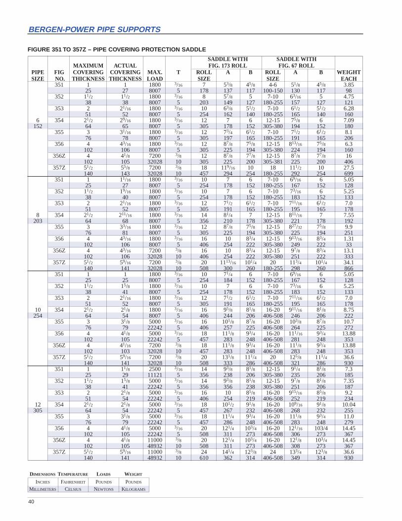
INCHES FAHRENHEIT POUNDS POUNDS
MILLIMETERS CELSIUS NEWTONS KILOGRAMS
DIMENSIONS TEMPERATURE LOADS WEIGHT
40
BERGEN-POWER PIPE SUPPORTS
SADDLE WITH SADDLE WITHMAXIMUM ACTUAL FIG. 173 ROLL FIG. 67 ROLL
PIPE FIG COVERING COVERING MAX. T ROLL A B ROLL A B WEIGHTSIZE NO. THICKNESS THICKNESS LOAD SIZE SIZE EACH
351 1 1 1800 3/16 7 53/8 45/8 4-6 51/8 45/8 3.8525 27 8007 5 178 137 117 100-150 130 117 98
352 11/2 11/2 1800 3/16 8 57/8 5 7-10 63/16 5 4.7538 38 8007 5 203 149 127 180-255 157 127 121
353 2 21/16 1800 3/16 10 63/8 51/2 7-10 61/2 51/2 6.2851 52 8007 5 254 162 140 180-255 165 140 160
6 354 21/2 29/16 1800 3/16 12 7 6 12-15 75/8 6 7.09152 64 65 8007 5 305 178 152 305-380 194 152 180
355 3 31/16 1800 3/16 12 73/4 61/2 7-10 71/2 61/2 8.176 78 8007 5 305 197 165 180-255 191 165 206
356 4 43/16 1800 3/16 12 87/8 75/8 12-15 813/16 75/8 6.3102 106 8007 5 305 225 194 305-380 224 194 160
356Z 4 41/8 7200 3/8 12 87/8 77/8 12-15 87/8 77/8 16102 105 32028 10 305 225 200 305-381 225 200 406
357Z 51/2 55/8 7200 3/8 18 119/16 10 18 111/2 10 27.5140 143 32028 10 457 294 254 180-255 292 254 699
351 1 11/16 1800 3/16 10 7 6 7-10 69/16 6 5.0525 27 8007 5 254 178 152 180-255 167 152 128
352 11/2 19/16 1800 3/16 10 7 6 7-10 73/16 6 5.2538 40 8007 5 254 178 152 180-255 183 152 133
353 2 21/16 1800 3/16 12 71/2 61/2 7-10 711/16 61/2 7.051 52 8007 5 305 191 165 180-255 195 165 178
8 354 21/2 211/16 1800 3/16 14 81/4 7 12-15 811/16 7 7.55203 64 68 8007 5 356 210 178 305-380 221 178 192
355 3 33/16 1800 3/16 12 87/8 75/8 12-15 827/32 75/8 9.976 81 8007 5 305 225 194 305-380 225 194 251
356 4 43/16 1800 3/16 16 10 83/4 12-15 913/16 83/4 1.31102 106 8007 5 406 254 222 305-380 249 222 33
356Z 4 43/16 7200 3/8 16 10 83/4 12-15 97/8 83/4 13.1102 106 32028 10 406 254 222 305-380 251 222 333
357Z 51/2 59/16 7200 3/8 20 1113/16 101/4 20 113/4 101/4 34.1140 141 32028 10 508 300 260 180-255 298 260 866
351 1 1 1800 3/16 10 71/4 6 7-10 69/16 6 5.0525 25 8007 5 254 184 152 180-255 167 152 128
352 11/2 15/8 1800 3/16 10 7 6 7-10 73/16 6 5.2538 41 8007 5 254 178 152 180-255 183 152 133
353 2 21/16 1800 3/16 12 71/2 61/2 7-10 711/16 61/2 7.051 52 8007 5 305 191 165 180-255 195 165 178
10 354 21/2 21/8 1800 3/16 16 95/8 81/8 16-20 911/16 81/8 8.75254 64 54 8007 5 406 244 206 406-508 246 206 222
355 3 31/8 5000 3/16 16 101/8 87/8 16-20 103/8 87/8 10.776 79 22242 5 406 257 225 406-508 264 225 272
356 4 41/8 5000 3/16 18 111/8 93/4 16-20 111/16 93/4 13.88102 105 22242 5 457 283 248 406-508 281 248 353
356Z 4 41/16 7200 3/8 18 111/8 93/4 16-20 111/8 93/4 13.88102 103 32028 10 457 283 248 406-508 283 248 353
357Z 51/2 59/16 7200 3/8 20 131/8 111/4 20 125/8 111/4 36.6140 141 32028 10 508 333 286 406-508 321 286 930
351 1 11/8 2500 3/16 14 93/8 81/8 12-15 91/4 81/8 7.325 29 11121 5 356 238 206 305-380 235 206 185
352 11/2 15/8 5000 3/16 14 93/8 81/8 12-15 97/8 81/8 7.3538 41 22242 5 356 356 238 305-380 251 206 187
353 2 21/8 5000 3/16 16 10 85/8 16-20 915/16 85/8 9.251 54 22242 5 406 254 219 406-508 252 219 234
12 354 21/2 21/8 5000 3/16 18 101/2 91/8 16-20 109/16 91/8 10.04305 64 54 22242 5 457 267 232 406-508 268 232 255
355 3 31/8 5000 3/16 18 111/4 93/4 16-20 111/8 93/4 11.076 79 22242 5 457 286 248 406-508 283 248 279
356 4 41/8 5000 3/16 20 121/4 103/4 16-20 121/16 103/4 14.45102 105 22242 5 508 311 273 406-508 306 273 367
356Z 4 41/8 11000 3/8 20 121/4 103/4 16-20 121/8 103/4 14.45102 105 48932 10 508 311 273 406-508 308 273 367
357Z 51/2 59/16 11000 3/8 24 141/4 123/8 24 133/4 123/8 36.6140 141 48932 10 610 362 314 406-508 349 314 930
FIGURE 351 TO 357Z – PIPE COVERING PROTECTION SADDLE

41
BERGEN-POWER PIPE SUPPORTS
SADDLE WITH SADDLE WITHMAXIMUM ACTUAL FIG. 173 ROLL FIG. 67 ROLL
PIPE FIG COVERING COVERING MAX. T ROLL A B ROLL A B WEIGHTSIZE NO. THICKNESS THICKNESS LOAD SIZE SIZE EACH
352 11/2 11/2 5000 3/16 16 101/4 9 16-20 103/8 9 8.2538 38 22242 5 406 260 229 406-508 264 229 210
353 2 2 5000 3/16 18 103/4 93/8 16-20 103/4 93/8 9.251 51 22242 5 457 273 238 406-508 273 238 234
354 21/2 21/8 5000 3/16 18 113/8 97/8 16-20 111/4 97/8 10.0464 54 22242 5 457 289 251 406-508 286 251 255
14 355 3 3 5000 3/16 18 12 101/2 16-20 113/4 101/2 11.0356 76 76 22242 5 457 305 267 406-508 298 267 279
356 4 4 5000 3/16 24 131/4 113/4 22-24 123/8 113/4 15.5102 102 22242 5 610 337 298 559-610 314 298 394
356Z 4 4 11000 3/8 24 123/4 111/4 22-24 117/8 111/4 15.5102 102 48932 10 610 324 286 559-610 302 286 394
357Z 51/2 51/2 11000 3/8 24 15 131/8 24 141/2 131/8 36.6140 140 48932 10 610 381 333 559-610 368 333 930
352 11/2 11/2 5000 3/16 18 111/8 93/4 16-20 111/4 93/4 8.2538 38 22242 5 457 283 248 406-508 286 248 210
353 2 2 5000 3/16 20 113/4 101/4 16-20 115/8 101/4 9.251 51 22242 5 508 298 260 406-508 295 260 234
354 21/2 21/2 7200 3/16 20 121/4 103/4 16-20 121/4 103/4 13.6964 64 32028 5 508 311 273 406-508 311 273 348
16 355 3 3 7200 3/16 24 127/8 111/8 22-24 127/8 111/8 14.65406 76 76 32028 5 610 327 283 559-610 327 283 372
356 4 4 7200 3/16 24 14 121/4 22-24 139/16 121/4 15.5102 102 32028 5 610 356 311 559-610 344 311 394
356Z 4 4 11000 3/8 24 14 121/4 22-24 135/8 121/4 15.5102 102 48932 10 610 356 311 559-610 346 311 394
357Z 51/2 51/2 11000 3/8 30 161/5 137/8 30 153/4 137/8 39140 140 48932 10 762 411 352 559-610 400 352 991
352 11/2 11/2 5000 3/16 20 121/4 103/4 16-20 121/4 103/4 9.3538 38 22242 5 508 311 273 406-508 311 273 237
353 2 2 7200 3/16 24 131/8 115/8 22-24 123/8 115/8 12.051 51 32028 5 610 333 295 559-610 314 295 305
354 21/2 21/2 7200 3/16 24 131/2 113/4 22-24 13 113/4 14.1964 64 32028 5 610 343 298 559-610 330 298 360
18 355 3 3 7200 3/16 24 14 121/4 22-24 131/2 121/4 15.25457 76 76 32028 5 610 356 311 559-610 343 311 387
356 4 4 7200 1/4 24 153/8 135/8 22-24 145/8 135/8 15.5102 102 32028 6 610 330 346 559-610 371 346 394
356Z 4 4 13200 3/8 24 151/8 133/8 22-24 143/8 133/8 15.5102 102 58719 10 610 384 340 559-610 365 340 394
357Z 51/2 51/2 13200 3/8 30 171/3 15 30 167/8 15 40140 140 58719 10 762 440 381 559-610 429 381 1016
352 11/2 11/2 7200 3/16 24 131/2 113/4 22-24 13 113/4 11.0538 38 32028 5 610 343 298 559-610 330 298 281
353 2 2 7200 3/16 24 14 121/4 22-24 131/2 121/4 12.451 51 32028 5 610 356 311 559-610 343 311 315
354 21/2 21/2 7200 3/16 24 145/8 127/8 22-24 141/8 127/8 14.1964 64 32028 5 610 371 327 559-610 359 327 360
20 355 3 3 7200 3/16 24 151/4 133/4 26-30 147/8 133/4 15.25508 76 76 32028 5 610 387 349 660-762 378 349 387
356 4 4 7200 1/4 30 161/2 141/4 26-30 153/4 141/4 16.6102 102 32028 6 762 359 362 660-762 400 362 422
356Z 4 4 13200 3/8 7 165/8 143/8 26-30 157/8 143/8 16.6102 102 58719 10 178 422 365 660-762 403 365 422
357Z 51/2 51/2 13200 3/8 30 181/3 16 30 177/8 16 42.4140 140 58719 10 762 465 406 660-762 454 406 1077
352 11/2 11/2 7200 3/16 30 163/8 141/8 26-30 153/4 141/8 12.9038 38 32028 5 762 416 359 660-762 400 359 328
353 2 2 7200 3/16 30 163/8 141/8 26-30 153/4 141/8 13.951 51 32028 5 762 416 359 660-762 400 359 352
354 21/2 21/2 7200 3/16 30 17 143/4 26-30 165/8 143/4 18.0764 64 32028 5 762 432 375 660-762 422 375 459
24 355 3 3 7200 1/4 30 171/2 151/4 26-30 171/8 151/4 19.35610 76 76 32028 6 762 445 387 660-762 435 387 491
356 4 4 7200 1/4 30 183/4 161/2 26-30 18 161/2 17.2102 102 32028 6 762 422 419 660-762 457 419 437
356Z 4 4 13200 3/8 30 187/8 165/8 26-30 181/8 165/8 17.2102 102 58719 10 762 479 422 660-762 460 422 437
FIGURE 351 TO 357Z – PIPE COVERING PROTECTION SADDLE

INCHES FAHRENHEIT POUNDS POUNDS
MILLIMETERS CELSIUS NEWTONS KILOGRAMS
DIMENSIONS TEMPERATURE LOADS WEIGHT
42
BERGEN-POWER PIPE SUPPORTS
E
LW
W
C – C
T
S
H DIA.
CHANNEL ASSEMBLYFigure 371
The Figure 371 Channel assembly is composedof two channels welded back to back with aspacer on each end. The washer plates, four (4),for the support rods are shipped loose.
The allowable safe loads are based on a factor ofsafety of five for the channels only.
Material: Carbon Steel.
Finish: Plain, Galvanized.
Ordering: Specify figure number, channel size,rod size and C to C dim. For Metric applications specify Figure M371.
FIGURE 371 – CHANNEL ASSEMBLY
ROD DIA3/8 1/2 5/8 3/4 7/8 1 11/4 11/2 13/4 2 21/4 21/2 23/4 3 31/4 31/210 13 16 19 22 25 32 38 44 51 57 64 70 76 83 89
H HOLE1/2 5/8 3/4 7/8 1 11/4 11/2 13/4 2 21/4 21/2 23/4 3 31/4 31/2 33/413 16 19 22 25 32 38 44 51 57 64 70 76 83 89 95
S9/16 11/16 13/16 15/16 11/16 13/8 15/8 17/8 21/4 21/2 23/4 3 31/4 31/2 33/4 414 17 21 24 27 35 41 48 57 64 70 76 83 89 95 102
W 3 3 3 4 4 4 5 5 5 5 6 6 6 6 6 776 76 76 102 102 102 127 127 127 127 152 152 152 152 152 178
T1/4 1/4 3/8 3/8 1/2 1/2 1/2 3/4 3/4 3/4 3/4 3/4 3/4 3/4 3/4 3/46 6 10 10 13 13 13 19 19 19 19 19 19 19 19 19
L3/8 3/8 3/8 3/8 3/8 3/8 3/8 3/8 3/8 3/8 3/8 3/8 3/8 1/2 1/2 1/210 10 10 10 10 10 10 10 10 10 10 10 10 13 13 13
ALLOWABLE CONCENTRATED LOAD AT CENTER OF SPANSPAN 12 18 24 30 36 42 48 60 72
305 441 610 762 914 1067 1219 1524 1829SIZE3] [4.1 10000 6800 5100 4100 3400 2900 2500 2000 1700
44484 30249 22687 18238 15125 12900 11121 8897 75624] [5.4 17500 11600 8800 7000 5800 5000 4400 3500 2900
77847 51601 39146 31139 25801 22242 19573 15569 129005] [6.7 27600 18400 13800 11000 9200 7900 6900 5500 4600
122776 81851 61388 48932 40925 35142 30694 24466 204636] [8.2 39500 26300 19800 15800 13200 11300 9900 7900 6600
175712 116993 88078 70285 58719 50267 44039 35142 293598] [11.5 74500 49600 37300 29800 24800 21300 18650 14900 12400
331406 220641 165925 132562 110320 94751 82963 66281 5516012] [20.7 — — 98500 78800 65600 56300 49200 39400 32800
— — 438167 350534 291815 250445 218861 175267 45907

BERGEN-POWER PIPE SUPPORTS
EXECUTIVE OFFICES
MASSACHUSETTS PENNSYLVANIA225 Merrimac Street 829 Beaver AvenueWoburn, MA 01801 Pittsburgh, PA 15233Tel: (781) 935-9550 Tel: (412) 323-1545Fax: (781) 935-7664 Fax: (412) 323-1904e-mail: [email protected] e-mail: [email protected]
MANUFACTURING PLANT
Eighth Street GateDonora Industrial ParkDonora, PA 15033