Bending - fast10.vsb.cz
15
Bending • Calculation of normal bending stress. • Neutral axis, cross-sectional modulus. • Bending of beams of asymmetrical cross-section. • Design and assessment of beams with elastic behavior of the material according to the ultimate limit state.
Transcript of Bending - fast10.vsb.cz

Bending
• Calculation of normal bending stress.• Neutral axis, cross-sectional modulus.• Bending of beams of asymmetrical cross-section.• Design and assessment of beams with elastic behavior
of the material according to the ultimate limit state.
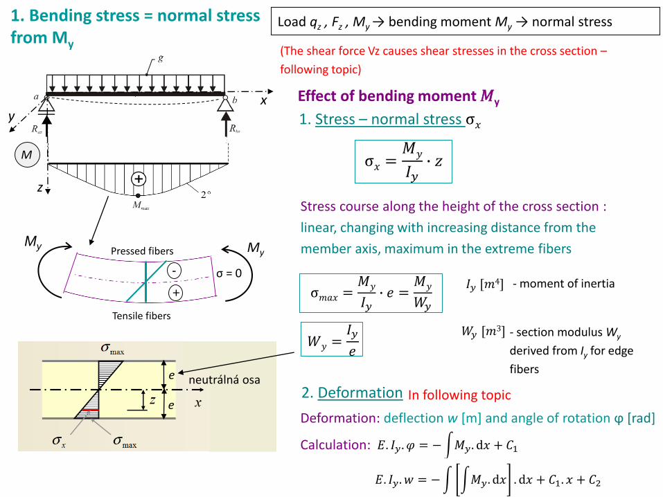
1. Bending stress = normal stress from My
Load qz , Fz , My → bending moment My → normal stress
σ𝑚𝑎𝑥 =𝑀𝑦
𝐼𝑦∙ 𝑒 =
𝑀𝑦
𝑊𝑦
Stress course along the height of the cross section :
linear, changing with increasing distance from the
member axis, maximum in the extreme fibers
1. Stress – normal stress σ𝑥
𝐼𝑦 [𝑚4]
Effect of bending moment 𝑀y
σ𝑥 =𝑀𝑦
𝐼𝑦∙ 𝑧
- moment of inertia
(The shear force Vz causes shear stresses in the cross section –
following topic)
𝑊𝑦 =𝐼𝑦
𝑒
- section modulus Wy
derived from Iy for edge
fibers
𝑊𝑦 [𝑚3]
+
M
e
e
neutrálná osa
Deformation: deflection w [m] and angle of rotation ϕ [rad]
Calculation:
2. Deformation
𝐸. 𝐼𝑦 . 𝜑 = −න𝑀𝑦. d𝑥 + 𝐶1
𝐸. 𝐼𝑦. 𝑤 = −න න𝑀𝑦. d𝑥 . d𝑥 + 𝐶1. 𝑥 + 𝐶2
In following topic
-
+
σ = 0
Tensile fibers
Pressed fibersMy My
x
z
y

1. Ultimate limit state:
MRd carrying capacity in design value
2. Serviceability limit state :
Normal stress σ [MPa]
𝑀𝐸𝑑 = 𝑀𝑚𝑎𝑥 maximal bending moment in design value
𝑀𝑅𝑑 ≥ 𝑀𝐸𝑑
The limiting deflection (entered) must be less than the actual deflection from the given load calculated in characteristic values.
Design and assessment of bending stress elements(symmetrical cross sections)
𝑤𝑙𝑖𝑚 ≥ 𝑤𝑟𝑒𝑎𝑙
𝑀𝑅𝑑 = 𝑓𝑦𝑑 ∙ 𝑊𝑦
fyd = 𝑓𝑦,𝑘
𝛾𝑀= σallow
In following topicsy
z
σmax,2
σmax,1
ee
σ = 0
Cross section
σ𝑚𝑎𝑥 =𝑀𝑦
𝐼𝑦∙ 𝑒 =
𝑀𝑦
𝑊𝑦
+
M
𝑀𝐸𝑑 = 𝑀𝑚𝑎𝑥
- Section modulus, we use for the design and
assessment of the cross-section, as it applies
to the extreme fibers of the cross-section,
where the stress is maximum
𝑊𝑦 [𝑚3]
- yield strength, material strength, maximum normal stress that the cross section transmits in the elastic state, for steel the same in tension and pressure
𝑓𝑦 [𝑃𝑎]
We calculate the stress in absolute value and determine the sign according to the sign of bending moments, for positive bending moments the lower fibers are tensile (+), for negative moments the upper fibers are tensile (+).
σ𝑚𝑎𝑥 =𝑀𝑦
𝑊𝑦+
-

Cross-sectional characteristics in bending :
• simple shapes and rolled profiles – tables
• compound shapes - calculation
1. Symmetrical cross sections:
2. Asymmetric cross sections :
σ𝑚𝑎𝑥, 1 = σ𝑚𝑎𝑥, 2 =𝑀
𝑊𝑦
𝑊1 = 𝑊2 = W
𝑊𝑦 =𝐼𝑦𝑒
σ1 ≠ σ 2
𝑊1 ≠ 𝑊2e2
e1
x
)(tlakW
M
hor
hor
)(tahW
M
doldol
y
z
σ𝑚𝑎𝑥 = σ1 =𝑀
𝑊𝑦, 1
The maximum stress arises in the fibers farther from the cross-sectional axis, eg at the T-section the lower fibers are (Wy, min):
𝐼 =𝜋 ∙ 𝑑4
64
𝑊 =𝜋 ∙ 𝑑3
32
𝐼 =1
12𝑏ℎ3
𝑊 =1
6𝑏ℎ2 𝑊 =
1
6𝑎3
𝐼 =1
12𝑎4
𝑊𝑦 =𝐼𝑦
𝑒[m3]
• Moment of inertia Iy [m4]
• Section modulus Wy [m3]
𝑒1 ≠ 𝑒 2
𝑒1 = 𝑒2 = e
2
1
σ𝑚𝑎𝑥 = σ1 =𝑀
𝑊𝑦, 1
σ2 =𝑀
𝑊𝑦,2
𝑒 =ℎ
2𝑒 =
𝑑
2𝑒 =
𝑎
2

Determine the value of maximum of normal stress in the upper and thelower fibres of the simple beam of the welded T profile.
1. Reactions, distribution of V (shear forces) and M (bending moments)
flange(160 x 16)
web (10 x 220)
T
q = 11 kN/m
l = 6 m
V [kN]
M [kNm]
Mmax = 49,5 kNm
2°
1°
Example 1
33
-33
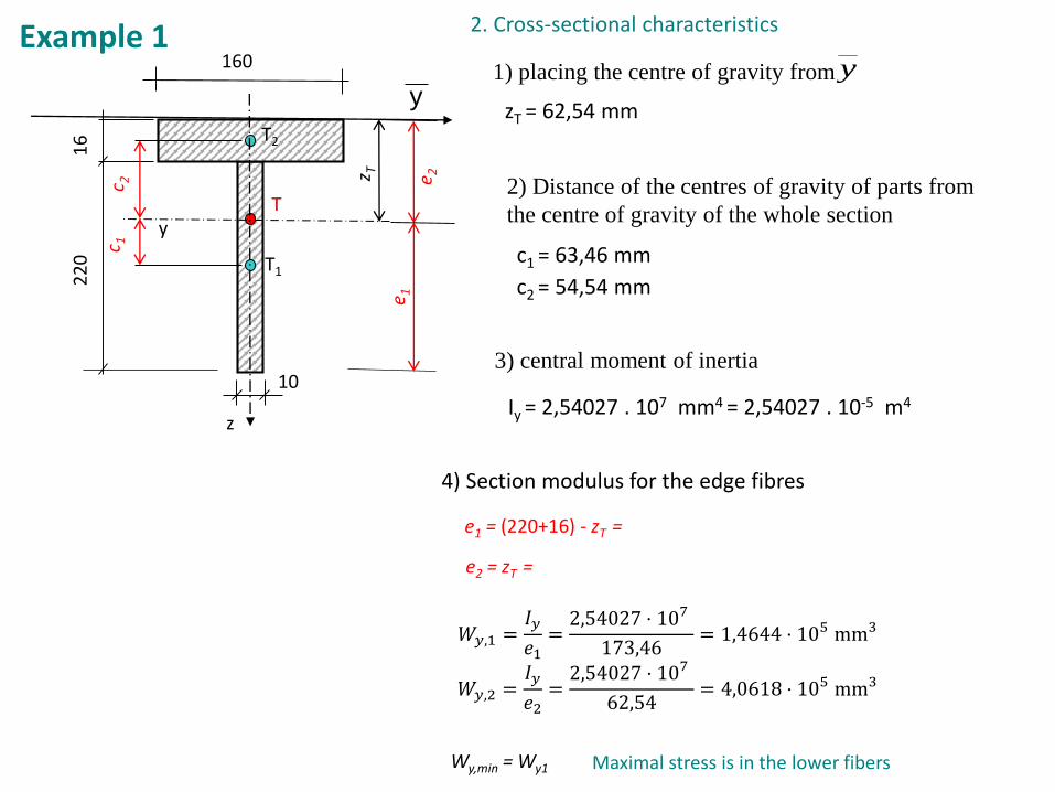
1) placing the centre of gravity from y
2) Distance of the centres of gravity of parts from
the centre of gravity of the whole section
3) central moment of inertia
4) Section modulus for the edge fibres
2. Cross-sectional characteristics
22
01
6
T1
T
10
c 1c 2
e 1e 2
y
z
zT = 62,54 mm
c1 = 63,46 mm
c2 = 54,54 mm
Iy = 2,54027 . 107 mm4 = 2,54027 . 10-5 m4
𝑊𝑦,1 =𝐼𝑦𝑒1=2,54027 ⋅ 107
173,46= 1,4644 ⋅ 105 mm3
𝑊𝑦,2 =𝐼𝑦𝑒2
=2,54027 ⋅ 107
62,54= 4,0618 ⋅ 105 mm3
e2 = zT =
e1 = (220+16) - zT =
Wy,min = Wy1 Maximal stress is in the lower fibers
Example 1
T2
y
160
z T

The signs of the stress are determined from the moment distribution (tensile / pressed fibers)
neutr. axes→ σ = 0
-108,6 MPa
301,1 MPa
45 m1054027,2 yI
𝑒2 = 62,54mm
𝑒1 = 173,46mm
𝜎2 =𝑀𝑚𝑎𝑥
𝑊𝑦,2= 121,88MPa (pressure)
𝜎1 = 𝜎𝑚𝑎𝑥 =𝑀𝑚𝑎𝑥
𝑊𝑦,1= 339,04MPa(tensile fibers)
σ in place of Mmax
3. Normal stress in the upper, lower fibers of the cross-section and in the place below the flange
𝑊𝑦,1 = 1,4644 ⋅ 105 mm3
𝑊𝑦,2 = 4,0618 ⋅ 105 mm3
22
01
6
T2
T1
T
10
160c 1
c 2
e 1e 2
y
-80,65 MPa
𝜎𝑓𝑙𝑎𝑛𝑔𝑒 =𝑀𝑚𝑎𝑥
𝐼𝑦. (𝑒2 − 0,016) =
49,5.103
2,54027.10−5. 0,0465 = 90,61MPa
σ𝑥 =𝑀𝑦
𝐼𝑦∙ 𝑧
𝜎1 = 𝜎𝑚𝑎𝑥 =𝑀𝑚𝑎𝑥
𝐼𝑦∙ e1= 339,04 MPa (tensile fibers)
𝜎2 =𝑀𝑚𝑎𝑥
𝐼𝑦∙ e2= 121,88 MPa (pressed fibers)
𝑧
𝑧 = 𝑒2 − 16
Alternatively:
+
M
-
+
Tensile fibers
Pressed fibersMy My
z(pressure)
Example 1

Example 2 - design and assessment of a circular cross-section according to ULS
Design and assess a steel beam of circular cross-sectionaccording to ULS, qk = 1,25 kNm-1, γQ =1,5, γM =1,00.Fe430 / S275.
q
3 0,51a b
2. Reactions and internal forces
1. 𝑞𝑑 = 𝑞𝑘 ∙ γQ = 1,25 ∙ 1,5 = 1,875 kN/m
𝑓𝑦,𝑑 =𝑓𝑦,𝑘𝛾𝑀
=275
1,0= 275 MPa
𝐹𝑖,𝑧 = 0:−4,923 − 3,516 + 1,875 ∙ 4,5 = 0
+
𝑀𝑖,𝑎 = 0:
𝑀𝑖,𝑏 = 0:
𝑅𝑎𝑧,𝑑 = 4,923 𝑘𝑁
𝑅𝑏𝑧,𝑑 = 3,516 𝑘𝑁
𝑞𝑑 = 1,875 kN/m
𝑄𝑑,1 ∙ 0,5 − 𝑄𝑑,2 ∙ 1,5 − 𝑄𝑑,3 ∙ 3,25 + 𝑅𝑏𝑧,𝑑 ∙ 3 = 0
𝑄𝑑,1 ∙ 3,5 + 𝑄𝑑,2 ∙ 1,5 − 𝑄𝑑,3 ∙ 0,25 − 𝑅𝑎𝑧,𝑑 ∙ 3 = 0
෨𝑄𝑑,1 = 𝑞𝑑 ∙ 1
෨𝑄𝑑,2 = 𝑞𝑑 ∙ 3
෨𝑄𝑑,3 = 𝑞𝑑 ∙ 0,5
𝑞𝑑
3 0,51a b
෨𝑄𝑑,1 ෨𝑄𝑑,2 ෨𝑄𝑑,3
𝑅𝑎𝑧,𝑑 𝑅𝑏𝑧,𝑑

Example 2
q
3 0,51
a b
-2,577-1,875
3,048
n
0,939
a bc
V
[kN]
xnP= 1,374xn
L=1,626
d
2°
2°
2°n
a bc d
1,53
-0,94-0,23
M
[kNm]
1° 1°
𝑥𝑛𝐿 =
𝑉𝑎𝑑𝑞𝑑
=3,048
1,875= 1,626 m
𝑥𝑛𝑅 =
𝑉𝑏𝑑𝑞𝑑
=2,577
1,875= 1,374 m
1°
𝑀𝑐 = 𝑀𝑑 =0
𝑀𝑎𝐿 = −𝑞𝑑 ∙
𝑥2
2= −1,875 ∙
1,02
2= −0,94 kNm
𝑀𝑛𝐿 = +𝑅𝑎𝑧,𝑑 ∙ 𝑥𝑛
𝐿 − 𝑞𝑑 ∙𝑥𝑛𝐿 + 1 2
2= 1,53 kNm
c d
Critical point:
𝑀𝑏𝑃 = −𝑞𝑑 ∙
𝑥2
2= −1,875 ∙
0,52
2= −0,23 kNm
𝑀𝑛𝑃 = +𝑅𝑏𝑧,𝑑 ∙ 𝑥𝑛
𝑃 − 𝑞𝑑 ∙𝑥𝑛𝑃+0,5
2
2= 1,53 kNm
Extremes of moments on the beam:
𝑀𝑛,𝑑 = 1,53 kNm
𝑀𝑎,𝑑 = −0,94 kNm
𝑀𝑏,𝑑 = −0,23 kNm𝑴𝒎𝒂𝒙 = 𝑴𝑬𝒅 = 𝟏, 𝟓𝟑 𝐤𝐍𝐦
You can also calculate bending moments with the help of substitute forces
𝑅𝑎𝑧,𝑑 = 4,92 𝑘𝑁 𝑅𝑏𝑧,𝑑 = 3,52𝑘𝑁
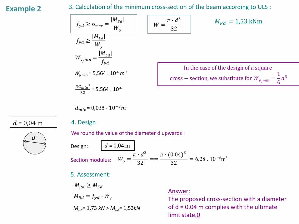
3. Calculation of the minimum cross-section of the beam according to ULS :
𝑊y,𝑚𝑖𝑛=𝑀𝐸𝑑
𝑓𝑦𝑑
𝜋𝑑𝑚𝑖𝑛3
32= 5,564 . 10-6
𝑑𝑚𝑖𝑛= 0,038 ∙ 10−3𝑚
𝑀𝐸𝑑 = 1,53 kNm𝑓𝑦𝑑 ≥ σ𝑚𝑎𝑥 =𝑀𝐸𝑑
𝑊𝑦
Example 2
𝑓𝑦𝑑 ≥𝑀𝐸𝑑
𝑊𝑦
Wy,min = 5,564 . 10-6 m3
5. Assessment:
4. Design
𝑀𝑅𝑑 = 𝑓𝑦𝑑 ∙ 𝑊y
We round the value of the diameter d upwards :
𝑑 = 0,04 mDesign:
𝑀𝑅𝑑 ≥ 𝑀𝐸𝑑
𝑊y =𝜋 ∙ 𝑑3
32==
𝜋 ∙ (0,04)3
32= 6,28 . 10 −6m3Section modulus:
MRd= 1,73 kN > MRd= 1,53kN
d
𝑑 = 0,04 m
Answer:The proposed cross-section with a diameter of d = 0.04 m complies with the ultimate limit state.0
In the case of the design of a square
cross − section,we substitute for 𝑊𝑦, 𝑚𝑖𝑛=1
6𝑎3
𝑊 =𝜋 ∙ 𝑑3
32

Example 3 Crosssetional characteristics1. The IPN pair is next to each other2. The IPN profiles are on top of each other
Tables: IPN 160: Wy = 1,17.105 mm3 = 1,17. 10-4 m3
1. The IPN pair is next to
each other
2. The IPN profiles are on
top of each other
Wy,1 = 1,17 ∙ 10-4 = m31.
2.
Wy= 2 x 1,17 ∙ 10-4 = 2,34 ∙ 10-4 m3
y
z
2 x IPN160
2 x IPN160
80
y
z
Iy = 2 ∙ 9,35 ∙ 10-6 = 18,7 ∙ 10-6 m4
Iy = 9,35. 106 mm4 = 9,35. 10-6 m4
𝑊𝑦 =𝐼𝑦𝑒=
18,7 ∙ 10−6
0,08= 2,34 ∙ 10−4 m3
Iy = 2 ∙ 9,35 ∙ 10-6 + 2 ∙ 2,28 ∙ 10-3 ∙ 0,082 = 4,79 ∙ 10-5 m4
𝑊𝑦 =𝐼𝑦𝑒=
4,79 ∙ 10−5
0,16= 2,99 ∙ 10−4 m3
e=160
e=80Iy calculate using Steiner's theorem, Wy compute
Wy can be taken directly as a double from the tables, it can be verified by calculating from Iy
A = 2,28. 103 mm2 = 2,28. 10-3 m2Tables IPN 160:

Other tablesI 160: Wy = 117.103 mm3 = 1,17. 10-4 m3
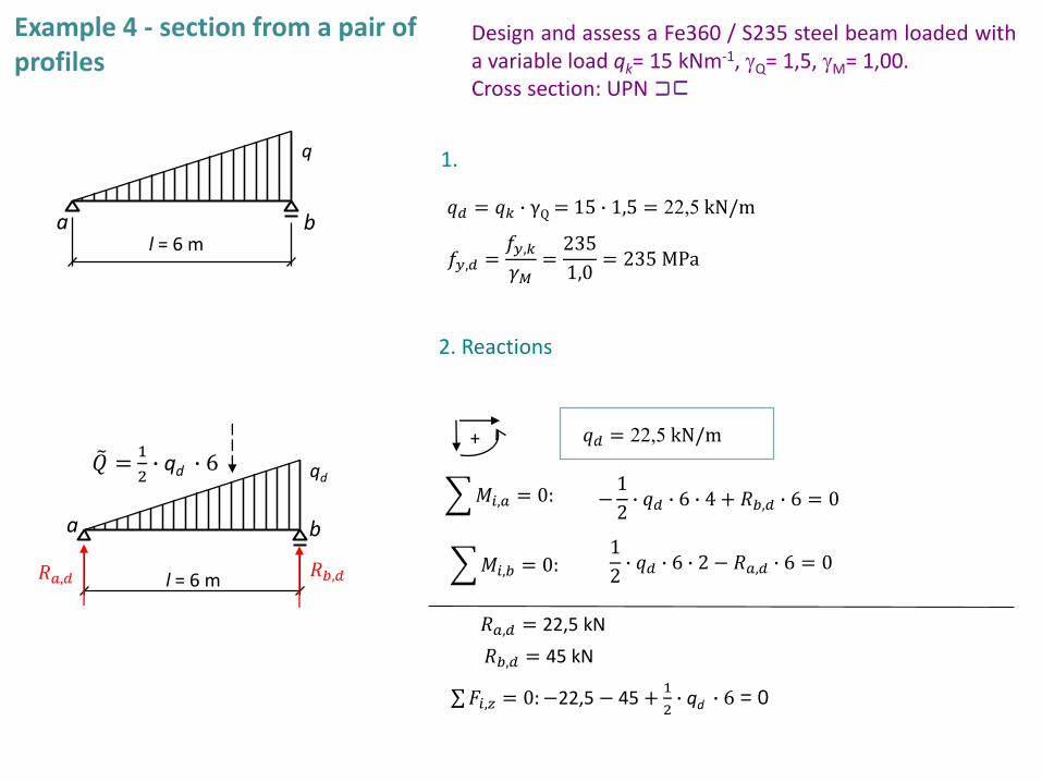
Example 4 - section from a pair of profiles
Design and assess a Fe360 / S235 steel beam loaded witha variable load qk= 15 kNm-1, gQ= 1,5, gM= 1,00.Cross section: UPN
l = 6 m
qd
U
U2. Reactions
1.
𝑞𝑑 = 𝑞𝑘 ∙ γQ = 15 ∙ 1,5 = 22,5 kN/m
𝑓𝑦,𝑑 =𝑓𝑦,𝑘𝛾𝑀
=235
1,0= 235 MPa
σ𝐹𝑖,𝑧 = 0:−22,5 − 45 +1
2∙ qd ∙ 6 = 0
+
𝑀𝑖,𝑎 = 0:
𝑀𝑖,𝑏 = 0:
𝑅𝑎,𝑑 = 22,5 kN
𝑅𝑏,𝑑 = 45 kN
𝑞𝑑 = 22,5 kN/m
−1
2∙ 𝑞𝑑 ∙ 6 ∙ 4 + 𝑅𝑏,𝑑 ∙ 6 = 0
1
2∙ 𝑞𝑑 ∙ 6 ∙ 2 − 𝑅𝑎,𝑑 ∙ 6 = 0𝑅𝑎,𝑑
෨𝑄 =1
2∙ qd ∙ 6
l = 6 m
q
a b
a b
𝑅𝑏,𝑑

𝑀𝑎 = 𝑀𝑏 =0
𝑀𝑚𝑎𝑥𝐿 = +𝑅𝑎,𝑑 ∙ 𝑥𝑛 −
𝑞𝑑 ∙ 𝑥𝑛3
6 ∙ 𝑙= 51,96 kNm
Critical point:
l = 6 m
qd =22,5kN/m
45
+
-
22,5
na b
V
[kN]
Xn= 3,464 2°
-45
a bM
[kNm]+
xMmax = 51,96
3°
෨𝑄 =1
2∙ qd ∙ 6
a b
22,5
𝑥𝑛𝐿 =
2 ∙ 𝑉𝑎∙ 𝑙
𝑞𝑑=
2 ∙ 22,5 ∙ 6
22,5= 3,464 m
3. Design according to ULS:
𝑊y,𝑚𝑖𝑛=𝑀𝐸𝑑
𝑓𝑦𝑑=
51,96
275∙103= 2,211.10-4 m3
𝑀𝐸𝑑 = 51,96 kNm
𝑓𝑦𝑑 ≥𝑀𝐸𝑑
𝑊y
Wy,min,1 = 2,211∙10−4
2=1,105 ∙ 10-4 m3 =1,105 ∙ 105 mm3
UPN160: Wy,1 = 1,16 ∙ 105 mm3 = 1,16 ∙ 10-4 m3
For 2U:
For 1U:
Tables:1U profil
2xUPN160: Wy = 2 ∙ 1,16.10-4 = 2,32 ∙ 10-4 m3Design:
Assessment:
MRd = 𝑓𝑦𝑑 ∙ 𝑊𝑦 = 235 ∙ 103 ∙ 2,32 . 10−4 = 54,52kNm
MRd= 54,52kNm > MEd = 51,96 kNm
Example 3
Answer:The proposed cross-section with a diameter of d = 0.04 m complies with the ultimate limit state.

Example 5 - homework Design and assess a steel beam from a rolled IPN profileaccording to ULS. Fe 360/S235, γM=1,00, γQ=1,5
qk = 7,5 kNm-1
6 1,5
1) Reactions Ra, Rb
2) V, M
3) Mmax= MEd
4) Determine Wy,min :
5) Design section:
6) Carrying capacity MRd
7) Assessment:
= 44,50 kNm
2 extrémes, chose Mmax
𝑓𝑦𝑑 ≥ 𝜎𝑚𝑎𝑥
𝑓𝑦𝑑 ≥𝑀𝐸𝑑
𝑊𝑦
𝑊𝑦, 𝑚𝑖𝑛=𝑀𝐸𝑑
𝑓𝑦𝑑= 1,8936.10-4m3
=2,14.10-4m3IPN200: Wy
→ satisfyingEdRd MM
𝑀𝑅𝑑 = 𝑓𝑦𝑑 ⋅ 𝑊𝑦
MRd = 50,29 kNm