Bedienungs- und Wartungsanleitung Operating and ... · Bedienungs- und Wartungsanleitung Operating...
32
Bedienungs- und Wartungsanleitung Operating and Maintenance Instructions Modelle / Models: SARA ® Ultra Cleaner UC1SD / S3, UC2SD / S3, UC3SD / S3 Auftrags-Nr. Order No. Stand 05 / 2012 As of 05 / 2012
Transcript of Bedienungs- und Wartungsanleitung Operating and ... · Bedienungs- und Wartungsanleitung Operating...

Bedienungs- undWartungsanleitung
Operating andMaintenance Instructions
Modelle / Models: SARA® Ultra Cleaner UC1SD/S3, UC2SD/S3, UC3SD/S3
Auftrags-Nr.Order No.
Stand 05 / 2012As of 05 / 2012

InhaltsverzeichnisTable of Contents
ATTENTION:Please read all chapters ofthis manual carefully before commencing any installationor maintenance work!
ACHTUNG:Bitte lesen Sie alle Punkte dieses Hand-buches sorgfältig, bevor Sie mit Installations- oder Wartungsarbeiten beginnen!
2
Allgemeine BeschreibungGeneral Description 3
SicherheitshinweiseSafety Notes 4
WARNUNGWARNING NOTES 5
Installation des GerätesInstallation of the Equipment 6-8
Aufbau und FunktionsbeschreibungSetup and Functional Description 9 -10
Technische DatenTechnical Data 11
Elektrischer AnschlussElectrical Connection 12-16
Reinigung und WartungCleaning and Maintenance 17-28
ErsatzteillisteSpare Parts List 29-30
InstallationsprüflisteInstallation Check List 31
HerstellererklärungManufacturer’s Declaration 32

3
� AerosolDispersionen von Fluidtröpfchenund Feststoffteilchen in gasförmigerUmgebung vorkommen.
� NebelFluidtröpfchen, die aus übersättigtem Dampfbei Temperatur / Druckabsenkung durchKondensieren entstehen bzw. vorhanden sind.
Allgemeine BeschreibungGeneral Description
SARA® Ultra-Cleaner sind geeignet zur Abscheidung von Schadstoffen, die in der Luft in Form von:
Die Geräte werden als anschlussfertige Einheit mit integriertem Ventilator geliefert. Das Gehäuse ist
stabil und verwindungsfrei aus Chromstahl lackiert in RAL 7035. Vier Füße mit Bohrungen erleichtern
die Installation des Gerätes. Durch Schnellverschlüsse in der seitlichen Wartungstür ist ein einfacher
Zugriff auf die Filterelemente gewährleistet. Am Bodenteil befindet sich eine mit einer 1-Zoll-Muffe und
Kugelhahn versehene öl- und wasserdichte Sammelwanne. Die am Gerät angebrachte Funktionsanzeige
zeigt den Verschmutzungsgrad des mehrstufigen Hochleistungsabscheidersystems an. Aerosole und
Flüssigkeitspartikel werden mechanisch durch das patentierte X-Cyclone® Grundelement Typ RXZ
abgeschieden. Über weitere Filterstufen werden mithilfe von Hochleistungsagglomeratoren feinste
Aerosole agglomeriert, sodass eine Abscheidung kleinster Tröpfchen gewährleistet ist.
� Alle Grundelemente und Agglomeratoren können abgereinigt
und wiederverwendet werden, keine Wegwerffilter!
Für besonders hohe Ölnebelbelastungen ist das Gerät
optional mit Schwebstoff- oder Elektrostataufsatz nachrüstbar.
Die Installation (siehe S. 6-8) der Geräte auf der Maschine
wird in dieser Bedienungsanleitung gesondert beschrieben.
SARA® Ultra Cleaners are suitable for the separationof air pollutants such as:
The devices are delivered ready for connection with an integrated fan. The stable and torsion-free
housing is made of chrome steel with a lacquer finish in RAL 7035. Four supports with drill holes facilitate
the installation of the device. The clip fasteners in the lateral maintenance door ensure easy access to
the filter elements. The bottom part is equipped with an oil and watertight collecting tray that is fitted with
a 1 inch sleeve and a ball cock. The maintenance indicator fitted to the device indicates the degree of
pollution of the multi-stage high-performance separating system. Aerosols and liquid particles are
mechanically separated by the patented X-Cyclone® basic element type RXZ. With additional filter stages,
the finest aerosols are agglomerated using high-performance agglomerators to ensure that even the
smallest droplets are separated.
� All basic elements and agglomerators can
be cleaned and reused – no throwaway filters!
In the event of particularly high pollution with oil mist, you can
retrofit the device with an optionally available electrostatic collector
top unit or a submicron particulate filter top unit. The installation of
the device is described separately on the pages 6 to 8 of this manual.
Alle SARA®
Ultra-Cleanerentsprechen
der europäischen
ErP Richtlinie!
� AerosolDispersions of fluid droplets and solid particles in a gaseous environment.
� MistFluid droplets generated from supersaturatedvapor through condensation when the temperature/pressure drops.
All SARA®
Ultra Cleanerscomply withthe European
ErP directive!

4
ACHTUNG:
Einsatz der Geräte in explosionsgefährdeter Umgebung
Die Abscheidegeräte werden ohne Explosionsschutz ausgeliefert. Dies bedeutet,
dass keine Dämpfe, Gase und Nebel abgesaugt werden dürfen, die im Gerät
� explosionsfähige Medien bilden oder selbst sind.
Absaugen von Medien mit niedrigem Flammpunkt
Durch die zunehmende Verwendung von Öl mit einem niedrigeren Flammpunkt auf
modernen Werkzeugmaschinen, � nimmt das Brand- und Verpuffungsrisiko bei
der Werkstoffverarbeitung generell zu. Wenden Sie sich im Zweifelsfall an
Fachfirmen für Brandschutzberatung und Brandschutzanlagen.
ATTENTION:
Use of the devices in environments with a high risk of explosion
Our separators are delivered without explosion protection. This means that no vapors,
gases and mists may be extracted that are explosive or might form � explosive media
inside the device.
Extraction of media with low ignition points
The steady increase in the use of oil with a low ignition point in modern machine tools
provokes a � generally increased risk of fire and explosion in the field of material
processing. In case of doubt, please contact a competent specialized provider of fire
protection consultancy services and equipment.
SicherheitshinweiseSafety Notes

5
WARNUNGWARNING NOTES
Eine Reinluftrückführung ist beim Umgang mit besonders krebserzeug-enden Gefahrstoffen nach § 15a der GefStoffV nicht erlaubt! Diese sind:
- 6-Amino-2-Ethoxynaphthalin
- 4-Aminobiphenyl und seine Salze
- Asbest
- Benzidin und seine Salze
- Bis(chlormethyl)äther
- Cadmiumchlorid (in atembarer Form)
- Chlormethyl-Methyläther
- Dimethylcarbamoylchlorid
- Hexamethylphosphorsäuretriamid
- 2-Naphthylamin und seine Salze
- 4-Nitrodiphenyl
- 1,3-Propansulton
- N-Nitrosaminverbindungen
- Tetranitromethan
- 1,2,3-Trichlorpropan
� In diesen Fällen müssen die Ultra Cleaner Geräte im Abluftbetrieb betrieben werden,
d. h. kein Rückführen der gereinigten Luft in den Aufenthaltsbereich von Menschen!
If any of the following hazardous substances is found in the extracted air of the machine, the cleaned air may under no circumstances be returned into areas where people congregate!
- 6-amino-2-ethoxynaphthalene
- 4-aminobiphenyl and its salts
- Asbestos
- Benzidine and its salts
- Bis(chlormethyl)ether
- Cadmium chloride (in respirable condition)
- Chloromethyl methyl ether
- Dimethylcarbamoylchloride
- Hexamethyl phosphoric acid triamide
- 2-naphtylamine and its salts
- 4-nitrodiphenyl
- 1,3-propane sultone
- N-nitrosamine compounds
- Tetranitromethane
- 1,2,3-Trichloropropane
� In these cases, the air extracted by the Ultra Cleaner devices must not be recirculated,
i. e. no cleaned air may be returned into areas where people congregate!

6
Installation des Gerätes IInstallation of the Equipment I
� Die SARA® Ultra-Cleaner müssen absolut waagerecht installiert werden.
� Der SARA® Ultra-Cleaner muss so aufgestellt werden, dass der Anschluss einer
Ölablaufleitung möglich ist.
� Des Weiteren ist zu beachten, dass der SARA® Ultra-Cleaner so installiert wird,
dass die Wartungstür zugänglich ist.
� SARA® Ultra Cleaners must be installed in an absolutely horizontal position.
� The SARA® Ultra Cleaner must be set up in such a way that it is possible
to connect an oil drain line.
� It should also be ensured that the maintenance door is easy accessible
after the installation of the SARA® Ultra Cleaner.
Installationsbeispiel – Direktmontage auf der Bearbeitungsmaschine:Installation example – direct installation on top of the processing machine:
Die Montagehilfe dient zum Abstützen des
Gerätes bei Transport und Montage. Sie
kann nach der Installation entfernt werden.
The assembling aid is used as a support
during transport and assembly. It can be
removed after the installation.
Installationsstandort auswählen.
Bei Montage direkt auf der Bearbeitungs-
maschine Tragfähigkeit beachten.
Choose the place of installation.
When installing the device on top of
the processing machine, check first
the bearing capacity of the machine.
Bei Montage direkt auf der Bearbeitungs-
maschine Lochbild anzeichnen und bohren
Eventuell daruterliegende Einbauten /
Traversen beachten.
When you install the device directly
on top of the machine, line up the hole pattern
and drill accordingly. Pay attention to any
rails or built-in units underneath!
1
2
3
AnsaugstutzenAir intake
Abb. zu 2Fig. Item 2
MontagehilfeAssembling aid
7
5
4
6
7
8
Installation des Gerätes IIInstallation of the Equipment II
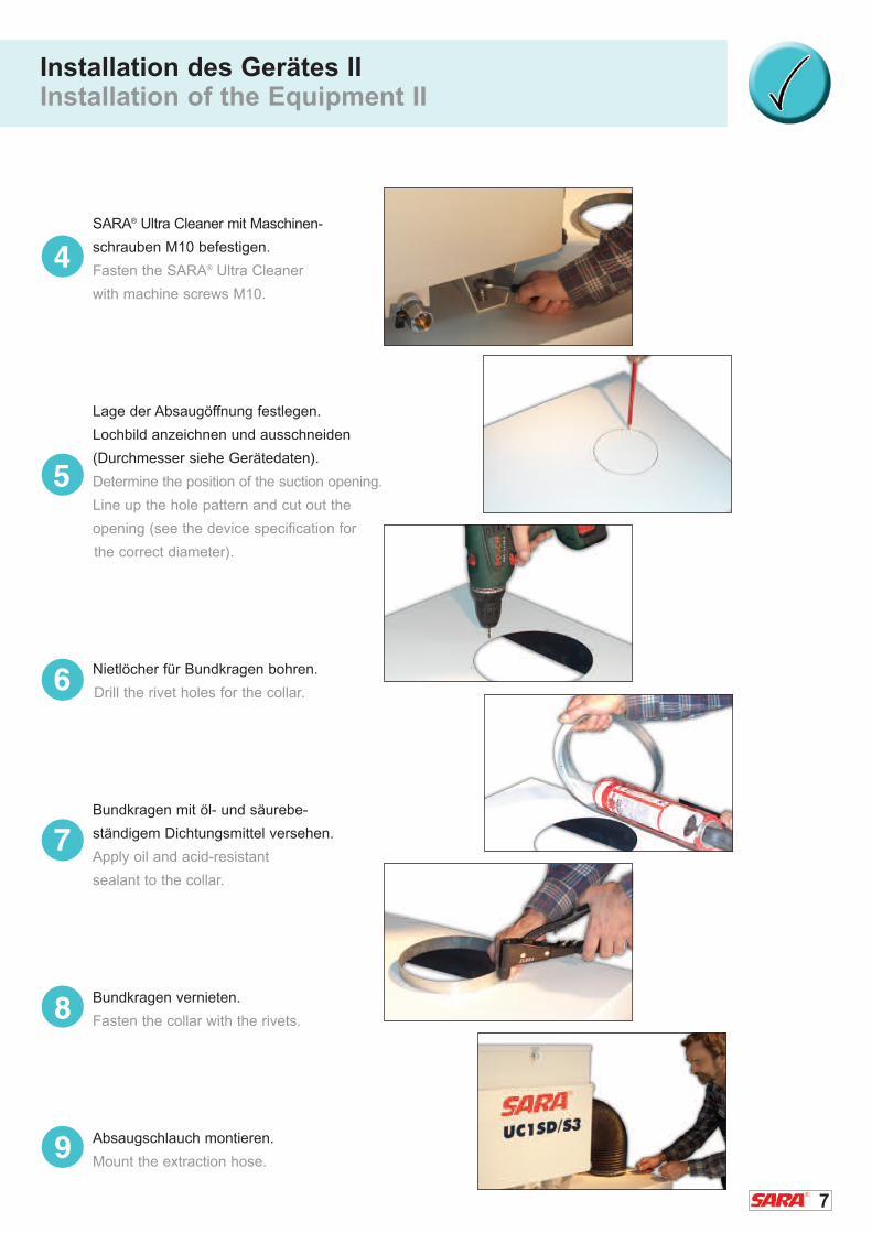
SARA® Ultra Cleaner mit Maschinen-
schrauben M10 befestigen.
Fasten the SARA® Ultra Cleaner
with machine screws M10.
Lage der Absaugöffnung festlegen.
Lochbild anzeichnen und ausschneiden
(Durchmesser siehe Gerätedaten).
Determine the position of the suction opening.
Line up the hole pattern and cut out the
opening (see the device specification for
the correct diameter).
Nietlöcher für Bundkragen bohren.
Drill the rivet holes for the collar.
Bundkragen mit öl- und säurebe-
ständigem Dichtungsmittel versehen.
Apply oil and acid-resistant
sealant to the collar.
Bundkragen vernieten.
Fasten the collar with the rivets.
Absaugschlauch montieren.
Mount the extraction hose.9
8
Installation des Gerätes IIIInstallation of the Equipment III
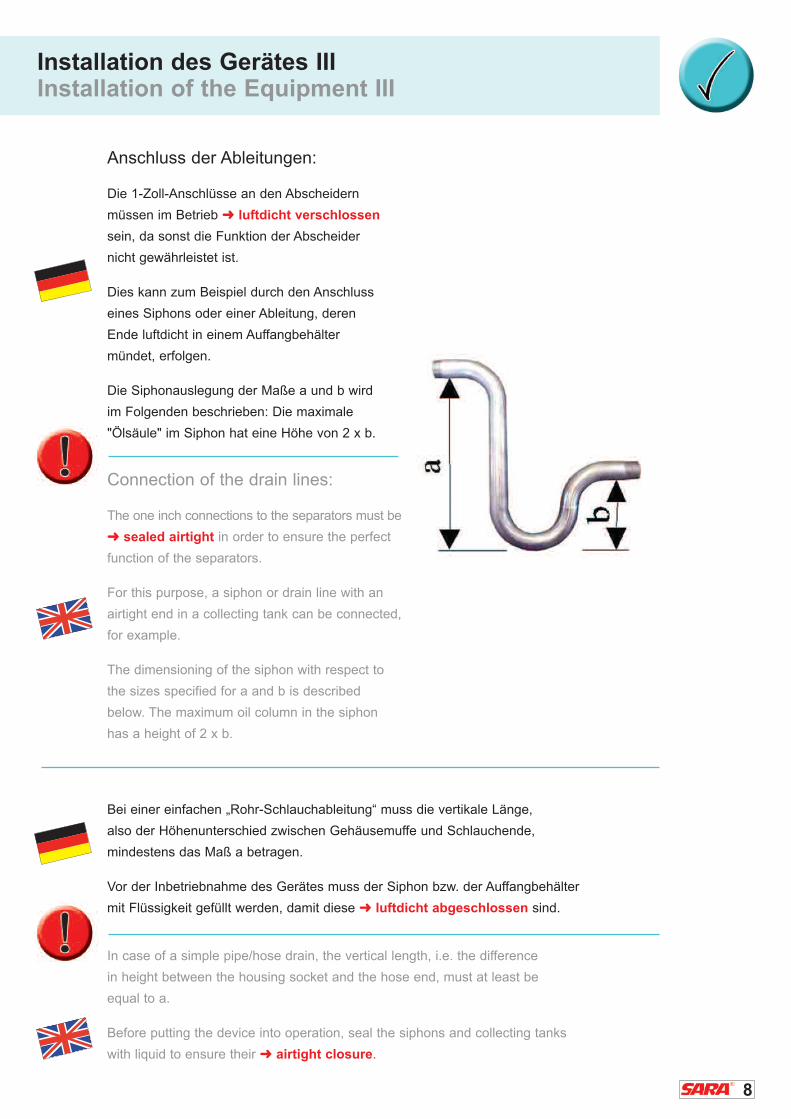
Anschluss der Ableitungen:
Die 1-Zoll-Anschlüsse an den Abscheidern
müssen im Betrieb � luftdicht verschlossen
sein, da sonst die Funktion der Abscheider
nicht gewährleistet ist.
Dies kann zum Beispiel durch den Anschluss
eines Siphons oder einer Ableitung, deren
Ende luftdicht in einem Auffangbehälter
mündet, erfolgen.
Die Siphonauslegung der Maße a und b wird
im Folgenden beschrieben: Die maximale
"Ölsäule" im Siphon hat eine Höhe von 2 x b.
Connection of the drain lines:
The one inch connections to the separators must be
� sealed airtight in order to ensure the perfect
function of the separators.
For this purpose, a siphon or drain line with an
airtight end in a collecting tank can be connected,
for example.
The dimensioning of the siphon with respect to
the sizes specified for a and b is described
below. The maximum oil column in the siphon
has a height of 2 x b.
Bei einer einfachen „Rohr-Schlauchableitung“ muss die vertikale Länge,
also der Höhenunterschied zwischen Gehäusemuffe und Schlauchende,
mindestens das Maß a betragen.
Vor der Inbetriebnahme des Gerätes muss der Siphon bzw. der Auffangbehälter
mit Flüssigkeit gefüllt werden, damit diese � luftdicht abgeschlossen sind.
In case of a simple pipe/hose drain, the vertical length, i.e. the difference
in height between the housing socket and the hose end, must at least be
equal to a.
Before putting the device into operation, seal the siphons and collecting tanks
with liquid to ensure their � airtight closure.

9
Aufbau und Funktionsbeschreibung ISetup and Functional Description I
SARA® Ultra-Cleaner werden als Einheit mit integriertem
Ventilator geliefert. Das Gehäuse ist stabil und verwindungsfrei aus
Chromstahl lackiert in RAL 7035. Wartungstür mit Schnellverschlüssen.
verschlüssen. Gehäuse innen glattflächig. Mehrstufiges Hochleistungs-
system. Am Bodenteil befindet sich eine mit einer 1-Zoll-Muffe und Kugel-
hahn versehene öl- und wasserdichte Sammelwanne. Aerosole und
Flüssigkeitspartikel werden mechanisch durch das patentierte X-Cyclone®
Grundelement Typ RXZ abgeschieden. Grundelement Typ RXZ
TÜV-geprüfter � Flammdurchschlagschutz, nach den Richtlinien
der US-amerikanischen Underwriters Laboratories®.
The SARA® Ultra Cleaner is delivered with an integrated fan.
The stable and torsion-free housing is made of chrome steel with
a lacquer finish in RAL 7035. The maintenance door is fitted with clip
fasteners. Smooth internal housing surfaces. Multi-stage high-performance
system. The bottom part is equipped with an oil and waterproof collecting
tray that is fitted with a 1 inch sleeve and a ball cock. Aerosols and liquid
particles are mechanically separated by the patented X-Cyclone® basic
element type RXZ. The � flame arresting capability of the basic element
type RXZ has been tested successfully by the German TÜV in compliance
with the directives of the American Underwriters Laboratories®.
Einbaurichtung!
Installation
position
Schalldämpfer / Sound absorber
Einschub 1 – 50 mm frei für optimale Filterbestückung
Rack 1 – 50 mm of free space for the easy insertion of filters
Einschub 3 – X-Cyclone® Typ RXZ
Rack 3 – X-Cyclone® type RXZ
Öl-Ablauf / Oil drain
Ansaugstutzen / Air intake
Gerätefüße / Device supports
Einschub 2 – Agglomerator / Rack 2 – agglomerator
Funktionsanzeige / Maintenance indicator
Montagehilfe / Assembling aid
Ventilator / Fan
Elektrischer Anschluss / Drehzahlregler
Electrical connection / Speed control
10
Aufbau und Funktionsbeschreibung IISetup and Functional Description II
Über weitere Filterstufen werden mithilfe von Hochleistungsagglomeratoren feinste
Aerosole agglomeriert, sodass eine Abscheidung kleinster Tröpfchen gewährleistet ist.
Alle Grundelemente und Agglomeratoren können abgereinigt und wiederverwendet werden,
� keine Wegwerffilter!
The finest aerosols are agglomerated via additional filter stages using high-performance
agglomerators to ensure that even the smallest droplets are separated. All basic
elements and agglomerators can be cleaned and reused � no throwaway filters!
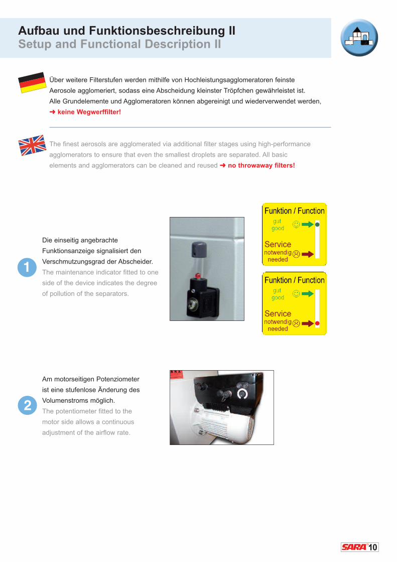
Die einseitig angebrachte
Funktionsanzeige signalisiert den
Verschmutzungsgrad der Abscheider.
The maintenance indicator fitted to one
side of the device indicates the degree
of pollution of the separators.
Am motorseitigen Potenziometer
ist eine stufenlose Änderung des
Volumenstroms möglich.
The potentiometer fitted to the
motor side allows a continuous
adjustment of the airflow rate.
1
2

11
Technische Daten Technical Data
Typ Leistung P Strom I Nennspannung U VentilatordrehzahlBetriebspunktdaten Betriebspunktdaten des Motors in n min-1
in Watt in Ampere in Volt (50Hz)
Type Performance P Current I Nominal voltage U Fan speed operating point value operating point value of the motor in n min-1
in Watts in Amperes in Volts (50Hz)
UC1SD/S3 500 1,3 3~400 2750
UC2SD/S3 880 2,3 3~400 2740
UC3SD/S3 1170 2,6 3~400 2820
* Volumenstrom max. bei sauberen Abscheidern
Volumenstrom min. bei stark verschmutzten Abscheidern bzw. langen Ansaugleitungen.
� Bitte beachten! Zulässige Umgebungstemperatur für alle Typen 0°C bis 40°C.
* Max. volume flow when the separators are clean.
Min. volume flow when the separators are severely polluted or the suction lines are very long.
� Please note! The admissible ambient temperature range is from 0 °C to 40 °C
for all types.
Typ Luftmenge* Höhe H Breite B Länge L Ø Anschluss RXZ Grund- ca. Gewichtin m3/h in mm in mm in mm element in kgmin./ max. Höhe x Breite
Type Air flow* Height H Width B Length L Ø Connection RXZ Basic Approx. in m3/h in mm in mm in mm Element weightmin./max. height x width in kg
UC1SD/S3 500 1000 640 360 865 200 330 x 330 44
UC2SD/S3 1000 2000 720 440 900 200 410 x 410 62
UC3SD/S3 2000 3000 800 520 945 300 490 x 490 93
+Null-Leiter+Neutral phase+Null-Leiter+Neutral phase
+Null-Leiter+Neutral phase
64
0
356,50 839
L LB W
H H
12
Arbeiten an elektrischen Bauteilen /-gruppen dürfen � nur von einer Elektrofachkraft
entsprechend den geltenden Vorschriften durchgeführt werden. Der Unternehmer oder
Betreiber hat ferner dafür zu sorgen, dass die elektrischen Anlagen und Betriebsmittel,
entsprechend den geltenden Vorschriften betrieben und instand gehalten werden.
Bei Arbeiten an elektrischen Bauteilen /-gruppen ist darauf zu achten, dass das Gerät mit
einem Reparaturschalter vom Netz getrennt und gegen Wiedereinschalten gesichert wird.
Die Geräte sind bereits anschlussfertig verdrahtet und wurden vor der Auslieferung sicher-
heitstechnisch überprüft. Sie entsprechen den VDE-Vorschriften.
ACHTUNG:Der Ultra-Cleaner muss an den örtlichen Potenzialausgleich angeschlossen werden.
Örtliche Leitungen müssen gegen Überlast und Kurzschluss abgesichert sein.
� Drehrichtung beachten!
Der elektrische Anschluss erfolgt in der Standardversion über den Drehzahlregler mit
Klemmverschlüssen. Hierzu ist bauseits eine 5-adrige Leitung (L1, L2, L3, PE) zu verlegen.
� Null-Leiter ist erforderlich bei optionalen elektrostatischen Nachfiltern!
Bitte beachten Sie die folgende Anschlusspläne (s. Seite 15-16).
Any work on electrical components/units may only be carried out by � electrical specialists
and must comply with applicable regulations. Furthermore, the contracting or operating
company must ensure that the electrical installations and working equipment are operated
and maintained in compliance with applicable regulations.
Before commencing any work on electrical components/units, make sure that you separate
the device from its power supply by means of a repair switch and secure it against
unintentional activation.
Our devices are wired ready for connection and their compliance with safety regulations was
tested prior to delivery. They comply with VDE directives.
ATTENTION:The Ultra Cleaner must be connected to the local potential equalization line. Local lines
must be secured against overload and short-circuits.
� Observe the direction of rotation!
As a standard, the electrical connection is realized with connecting terminals via the speed
control. The required 5-conductor supply line (L1, L2, L3, PE) shall be installed by the customer.
� Neutral-phase is necessary if optional after-filters will be installed.
Please observe the following connecting plans (see page 15-16).
Elektrischer Anschluss IElectrical Connection I

13
Überprüfung der VentilatordrehrichtungACHTUNG:
� Bitte unbedingt die richtige Ventilatordrehrichtung beachten. Das Gerät saugt aufgrund
der Ventilatorform immer durch den Ansaugstutzen an. Eine falsche Drehrichtung
bewirkt eine stark verminderte Leistung des Geräts und kann den Ventilatormotor
dauerhaft beschädigen.� Bei falschem Anschluss übernehmen wir keine Garantie!
� Prüfen Sie die Drehrichtung von der Befestigung des Motors ausgehend.
Der Ventilator dreht immer gegen den Uhrzeigersinn!
� Schutzbrille tragen!
Verification of the fan's direction of rotationATTENTION:
� Please observe the direction of rotation of the fan under all circumstances. The device
sucks the air always in through the air intake due to the shape of the fan. If the fan
runs in the wrong direction the performance of the device is considerably reduced
and the fan motor might be damaged or even destroyed.� Our guarantee does
not cover an incorrect connection of the fan!
� Check the direction of rotation from the position where the motor is fixed.
The fan should always rotate counter clockwise!
� Use safety classes!
Prüfung der Ventilator-Drehrichtung:Vertification of the fan’sdirection of rotation:
Nach Entfernen des Schalldämpferschaums kann die
� Ventilatordrehrichtung ohne Gefahr geprüft werden!
After removal of the sound-absorbing cellular mat, you can
� safely check the direction of rotation of the fan!
ACHTUNG:Unbedingt diese Richtung einhalten!
ATTENTION: The fan must run indirection of the arrow.
Elektrischer Anschluss IIElectrical Connection II
14
Elektrischer Anschluss IIIElectrical Connection III
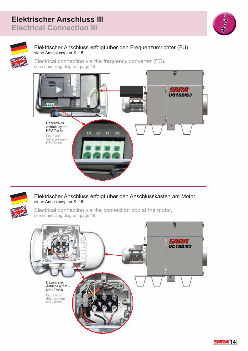
Dezentrales Antriebssytem –KFU-Tronik
Fig.: Local drive system –KFU Tronic
Elektrischer Anschluss erfolgt über den Frequenzumrichter (FU),siehe Anschlussplan S. 15.
Electrical connection via the frequency converter (FC),see connecting diagram page 15.
Elektrischer Anschluss erfolgt über den Anschlusskasten am Motor,siehe Anschlussplan S. 16.
Electrical connection via the connection box at the motor,see connecting diagram page 16.
Dezentrales Antriebssytem –KFU-Tronik
Fig.: Local drive system –KFU Tronic
15
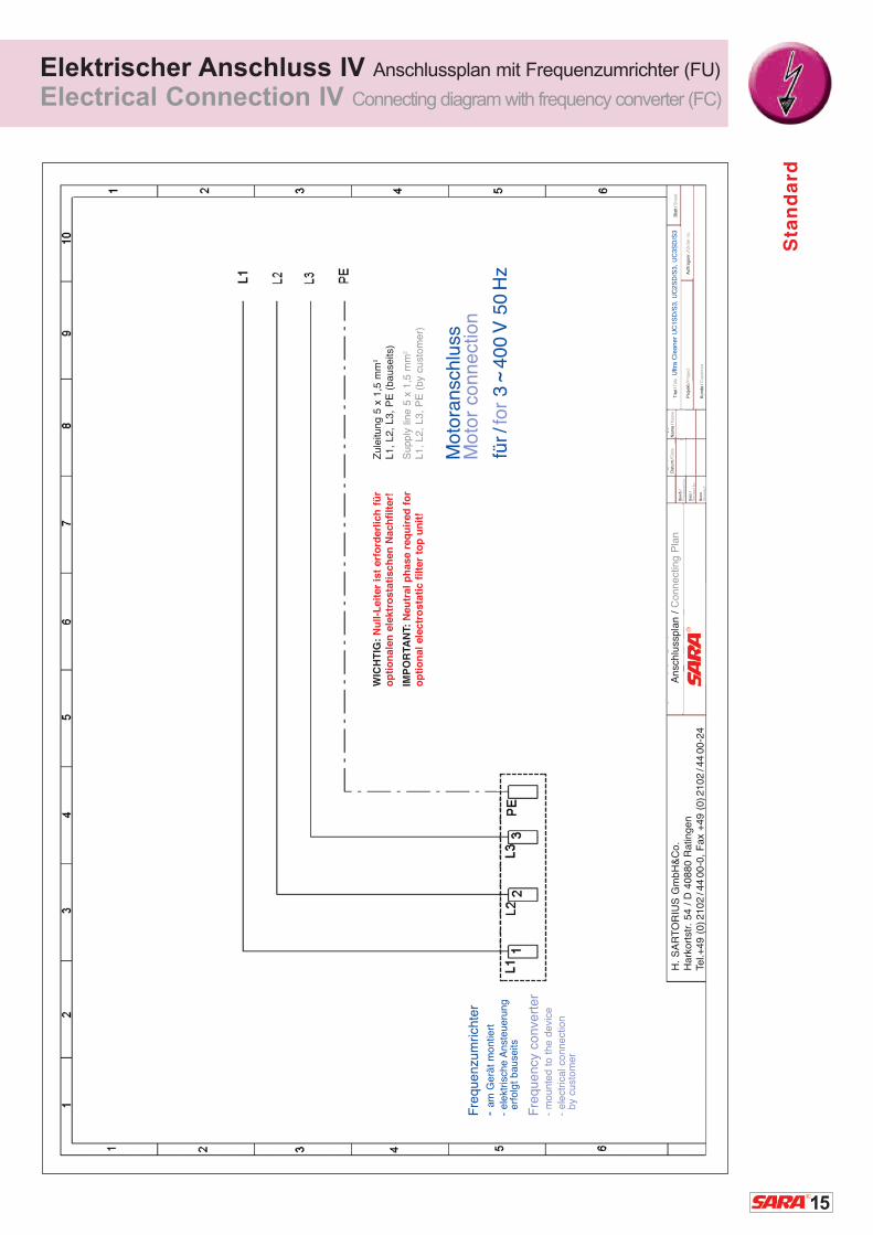
Elektrischer Anschluss IV Anschlussplan mit Frequenzumrichter (FU)
Electrical Connection IV Connecting diagram with frequency converter (FC)
Ansc
hlu
sspla
n /
Connect
ing P
lan
H.
SA
RT
OR
IUS
Gm
bH
&C
o.
Hark
ort
str. 5
4 /
D 4
0880 R
atin
gen
Tel.+
49 (
0)2
102
/44
00-0
, F
ax
+49 (
0)2
102
/44
00-2
4
Datu
m/D
ate
Bearb
./P
roce
ssed b
y
Gepr.
/R
evi
sed b
y
Norm
Sta
ndard
Nam
e/N
am
eT
itel/
Titl
e U
ltra C
leaner
UC
1S
D/S
3,
UC
2S
D/S
3,
UC
3S
D/S
3
Pro
jekt
/Pro
ject
Auftra
gsn
r./O
rder
no.
Bla
tt/S
heet
Kunde
/Cust
om
er
Fre
quenzu
mrich
ter
- am
Gerä
t m
ontie
rt
- ele
ktrisc
he A
nst
eueru
ng
erf
olg
t bause
its
Fre
quency
conve
rter
- m
ounte
d t
o t
he d
evi
ce
- ele
ctrica
l co
nnect
ion
by
cust
om
er
Zule
itung 5
x 1
,5 m
m2
L1,
L2,
L3,
PE
(bause
its)
Supply
lin
e 5
x 1
,5 m
m2
L1,
L2,
L3,
PE
(by
cust
om
er)
WIC
HT
IG:
Nu
ll-L
eit
er
ist
erf
ord
erl
ich
für
op
tio
nale
n e
lektr
osta
tisch
en
Nach
filt
er!
IMP
OR
TA
NT:
Neu
tral
ph
ase
req
uir
ed
fo
r
op
tio
nal
ele
ctr
osta
tic f
ilte
r to
p u
nit
!
Sta
nd
ard
Moto
ransc
hlu
ssM
oto
r co
nnect
ion
für/
for
3
400
V 5
0H
z˜
16
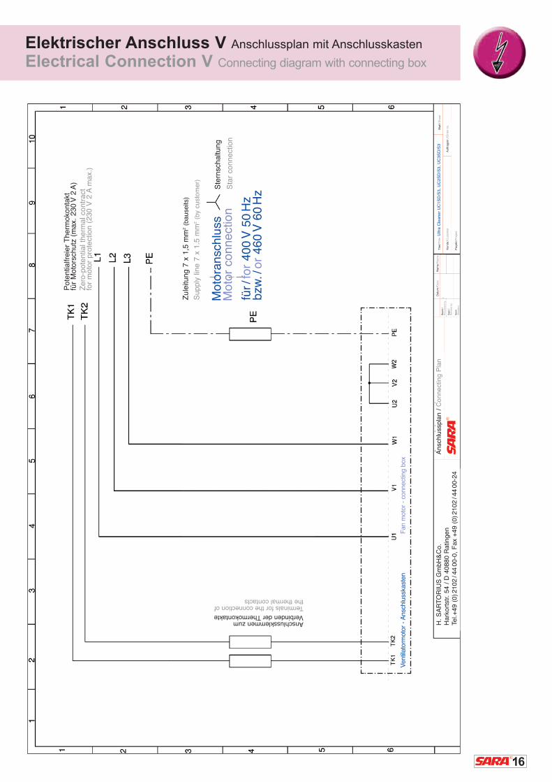
Elektrischer Anschluss V Anschlussplan mit Anschlusskasten
Electrical Connection V Connecting diagram with connecting box
Datu
m/D
ate
Bearb
./P
roce
ssed b
y
Gepr.
/R
evi
sed b
y
Norm
Sta
ndard
Nam
e/N
am
eT
itel/
Titl
e U
ltra C
leaner
UC
1S
D/S
3,
UC
2S
D/S
3,
UC
3S
D/S
3
Kunde
/Cust
om
er
Auftra
gsn
r./O
rder
no.
Bla
tt/S
heet
Pro
jekt
/Pro
ject
RE
VE
N L
üftungss
yste
me,
Um
weltt
ech
nik
Gm
bH
Ludw
igst
r. 1
6-1
8 /
D-7
4372 S
ers
heim
Tel.
+49
(0)7
0429
/373-0
, F
ax
+49
(0)7
042
/373-2
0
Ansc
hlu
sspla
n /
Connect
ing P
lan
Pote
ntia
lfreie
r T
herm
oko
nta
ktfü
r M
oto
rsch
utz
(m
ax.
230
V 2
A)
Zero
-pote
ntia
l th
erm
al co
ntr
act
for
moto
r pro
tect
ion (
230 V
2 A
max.
)
Moto
ransc
hlu
ssM
oto
r co
nnect
ion
Ste
rnsc
haltu
ng
Sta
r co
nnect
ion
für/
for
400
V 5
0H
zbzw
./or
460
V 6
0H
z
Ventil
ato
rmoto
r - A
nsc
hlu
sska
sten
Fan m
oto
r -
connect
ing b
ox
Zule
itung 7
x 1
,5 m
m2
(bause
its)
Supply
lin
e7 x
1.5
mm
2(b
y cu
stom
er)
H.
SA
RT
OR
IUS
Gm
bH
&C
o.
Hark
ort
str. 5
4 /
D 4
0880 R
atin
gen
Tel.+
49 (
0)2
102
/44
00-0
, F
ax
+49 (
0)2
102
/44
00-2
4
Anschlussklemmen zum Verbinden der Thermokontakte
Terminals for the connection ofthe thermal contacts

17
Reinigung und Wartung der Abscheider
Weisen die X-Cyclone®-Grundelemente Typ RXZ (Aluminium-Filterstufe) oder die AGG
Agglomeratoren Verschmutzungen in Form von Verharzungen oder Filterkuchen auf,
sind diese mithilfe eines Hochdruckreinigers oder einer Industriewaschmaschine
z. B. zu reinigen. Bei der Abscheidung von Medien, die wegen der möglichen Bildung
von Schimmelkulturen, Viren oder Bakterien eine mikrobiologische oder biologische
Gefährdung darstellen, müssen unbedingt
� regelmäßige, kurze Wartungs- und Reinigungsintervalle eingehalten werden.
� Zur Reinigung der Filteranlage empfehlen wir den biologischen Entöler Oil-Free V2000.
Cleaning and Maintenance of the Separators
If the X-Cyclone® basic elements type RXZ (aluminum filter stage) or the AGG agglomerators
show strong contamination in the form of gumming or filter caking, they should be
cleaned with the help of a high-pressure cleaner or an industrial washing machine, for
example. If the media to be separated constitute a biological or microbiological hazard
because they form mildew cultures, viruses or bacteria, for example, it is imperative that
� regular maintenance and cleaning cycles be observed in short intervals.
� We recommend the biological oil remover Oil-Free V2000 for the cleaning of the filter system.
Gehen Sie wie folgt vor: / Follow the instructions below:
Filtergerät ausschalten und vorm Öffnen der Wartungstür
mithilfe eines Reparaturschalters vom Netz trennen.
Switch off the filter device and separate it from the power supply
with the help of a repair switch before opening the maintenance door.
Wenn im Abscheider gesundheitsgefährdende Stoffe abgeschieden werden, muss vor
dem Öffnen der Wartungstür eine entsprechende Schutzausrüstung angelegt werden.
� Sonst besteht je nach Abscheidemedium Vergiftungs-,
Verätzungs- und/oder Verbrennungsgefahr.
If materials that are hazardous to your health are separated in the device,
put appropriate protective clothing on before you open the maintenance door.
� This helps to avoid burns, poisoning and / or caustic burns
depending on the nature of the separated medium.
Vorm Öffnen der Wartungstür Ventilatorstillstand abwarten.
Wait until the fan has stopped rotating before you open the maintenance door.
2
1
3
Reinigung und Wartung ICleaning and Maintenance I

18
Die Wartungstür öffnen und die Elemente
aus dem Gehäuse herausziehen.
� Um die Wartungsarbeit zu erleichtern,
kann die Wartungstür ausgehängt werden.
Open the maintenance door and extract
the elements from the housing.
� For easier access to the interior of the
device, unhinge the maintenance door.
Bei der Wiedermontage der Plattenebenen ist darauf zu achten, dass die Elemente in
die Dränageaufnahme � richtig eingeführt werden und die � Filterprofile vertikal
angeordnet sind.
When reassembling the plate levels, make sure that the elements are � reinstalled correctly
into the drainage receiver and the � filter profiles are in vertical position.
5
Reinigung und Wartung IICleaning and Maintenance II
4
Abb.: FEHLEN?!
Abb.: X-Cyclone® Grundelement Fig.: X-Cyclone® basic element
Abb.: Einbau-Bsp. für ein RXZ-Grundelementin einem SARA® Ultra Cleaner
Fig.: Assembly example of an RXZ basic element in a SARA® Ultra Cleaner
Einbaurichtung!
Installation
position
Reinigung und Wartung IIICleaning and Maintenance III
19
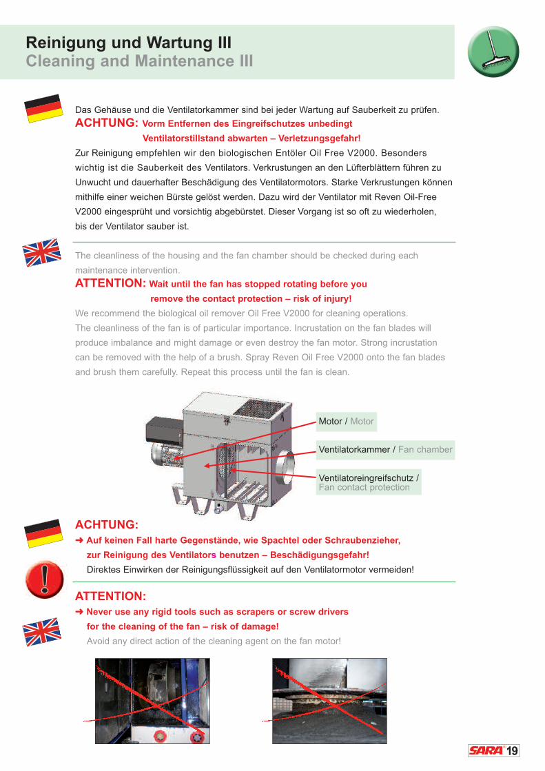
Das Gehäuse und die Ventilatorkammer sind bei jeder Wartung auf Sauberkeit zu prüfen.
ACHTUNG: Vorm Entfernen des Eingreifschutzes unbedingt
Ventilatorstillstand abwarten – Verletzungsgefahr!
Zur Reinigung empfehlen wir den biologischen Entöler Oil Free V2000. Besonders
wichtig ist die Sauberkeit des Ventilators. Verkrustungen an den Lüfterblättern führen zu
Unwucht und dauerhafter Beschädigung des Ventilatormotors. Starke Verkrustungen können
mithilfe einer weichen Bürste gelöst werden. Dazu wird der Ventilator mit Reven Oil-Free
V2000 eingesprüht und vorsichtig abgebürstet. Dieser Vorgang ist so oft zu wiederholen,
bis der Ventilator sauber ist.
The cleanliness of the housing and the fan chamber should be checked during each
maintenance intervention.
ATTENTION: Wait until the fan has stopped rotating before you
remove the contact protection – risk of injury!
We recommend the biological oil remover Oil Free V2000 for cleaning operations.
The cleanliness of the fan is of particular importance. Incrustation on the fan blades will
produce imbalance and might damage or even destroy the fan motor. Strong incrustation
can be removed with the help of a brush. Spray Reven Oil Free V2000 onto the fan blades
and brush them carefully. Repeat this process until the fan is clean.
ACHTUNG:� Auf keinen Fall harte Gegenstände, wie Spachtel oder Schraubenzieher,
zur Reinigung des Ventilators benutzen – Beschädigungsgefahr!
Direktes Einwirken der Reinigungsflüssigkeit auf den Ventilatormotor vermeiden!
ATTENTION:� Never use any rigid tools such as scrapers or screw drivers
for the cleaning of the fan – risk of damage!
Avoid any direct action of the cleaning agent on the fan motor!
Motor / Motor
Ventilatorkammer / Fan chamber
Ventilatoreingreifschutz / Fan contact protection

Reinigung und Wartung IVCleaning and Maintenance IV
Überprüfung der Türdichtung:
Die Türdichtung der SARA® Ultra Cleaner unterliegt einem Alterungsprozess.
� Bei Undichtheiten, Aushärtungen oder Beschädigungen muss die Türdichtung
ausgetauscht werden. Die Türdichtung ist auf das Rahmenprofil aufgesteckt –
� ein Auswechseln der Dichtung ist ohne großen Aufwand möglich!
Check the door seal:
The door seal of the SARA® Ultra Cleaner is affected by ageing.
� If any leakage, age hardening or damage becomes apparent, the door seal
must be replaced. The door seal is fitted onto the frame section –
� and can easily be replaced!
ACHTUNG:
� Der Stoß der Dichtung muss immer oben sein. Die Dichtung zeigt mit den
drei Dichtungslippen immer zur abzudichtenden Seite (also zum Inneren des Gehäuses)!
ATTENTION:
� The butt joint of the seal must always be on top. The three sealing lips should
always face the side to be sealed (which is the housing interior).
Alte Dichtung entfernen.
Remove the old seal.
Neue Dichtung montieren.
Install the new seal. 2
1
20

21
Reinigung des Schalldämpfers:
Der auf dem Gerät fest aufgesetzte
Schalldämpfer wird mittels vier Schnell-
verschlüssen geöffnet. Die unter dem Deckel
liegende Schaumstoffmatte ist nach Bedarf
auszuwaschen oder auszuwechseln.
Cleaning of the sound absorber:
The sound absorber firmly attached to the
top of the device can be removed by opening
the four clip fasteners. The cellular plastic
mat underneath the cover should be washed
or replaced if required.
Die Schaumstoffmatte hat zwei unterschiedliche Funktionsweisen:
The cellular plastic mat fulfills two different functions:
Geräuschdämmung
Soundproofing
ACHTUNG:
� Nach Reinigung des Schalldämpfers ist darauf zu achten, dass die Luftaustrittsöffnung
des Deckels gegenüber der Luftaustrittsöffnung der Ventilatorenkammer sitzen muss.
ATTENTION:
� After cleaning the sound absorber, make sure that the exhaust air opening of the lid faces
the one of the fan chamber on the opposite side.
1
Filterkammer / Filter chamberVentilatorkammer / Fan chamber
Durch den Ventilator können kondensierte
Öltröpfchen ausgeschleudert werden.
Diese werden in der Schaumstoffmatte
gesammelt und können abtropfen.
The fan can eject condensed oil droplets.
These are collected in the cellular plastic
mat and can drip off.
2
Reinigung und Wartung VCleaning and Maintenance V
22
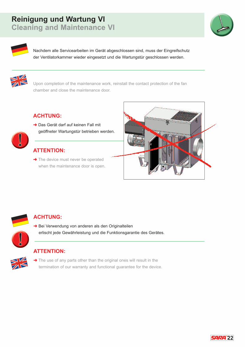
Nachdem alle Servicearbeiten im Gerät abgeschlossen sind, muss der Eingreifschutz
der Ventilatorkammer wieder eingesetzt und die Wartungstür geschlossen werden.
Upon completion of the maintenance work, reinstall the contact protection of the fan
chamber and close the maintenance door.
ACHTUNG:
� Das Gerät darf auf keinen Fall mit
geöffneter Wartungstür betrieben werden.
ATTENTION:
� The device must never be operated
when the maintenance door is open.
Reinigung und Wartung VICleaning and Maintenance VI
ACHTUNG:
� Bei Verwendung von anderen als den Originalteilen
erlischt jede Gewährleistung und die Funktionsgarantie des Gerätes.
ATTENTION:
� The use of any parts other than the original ones will result in the
termination of our warranty and functional guarantee for the device.
23
Reinigung und Wartung VIICleaning and Maintenance VII
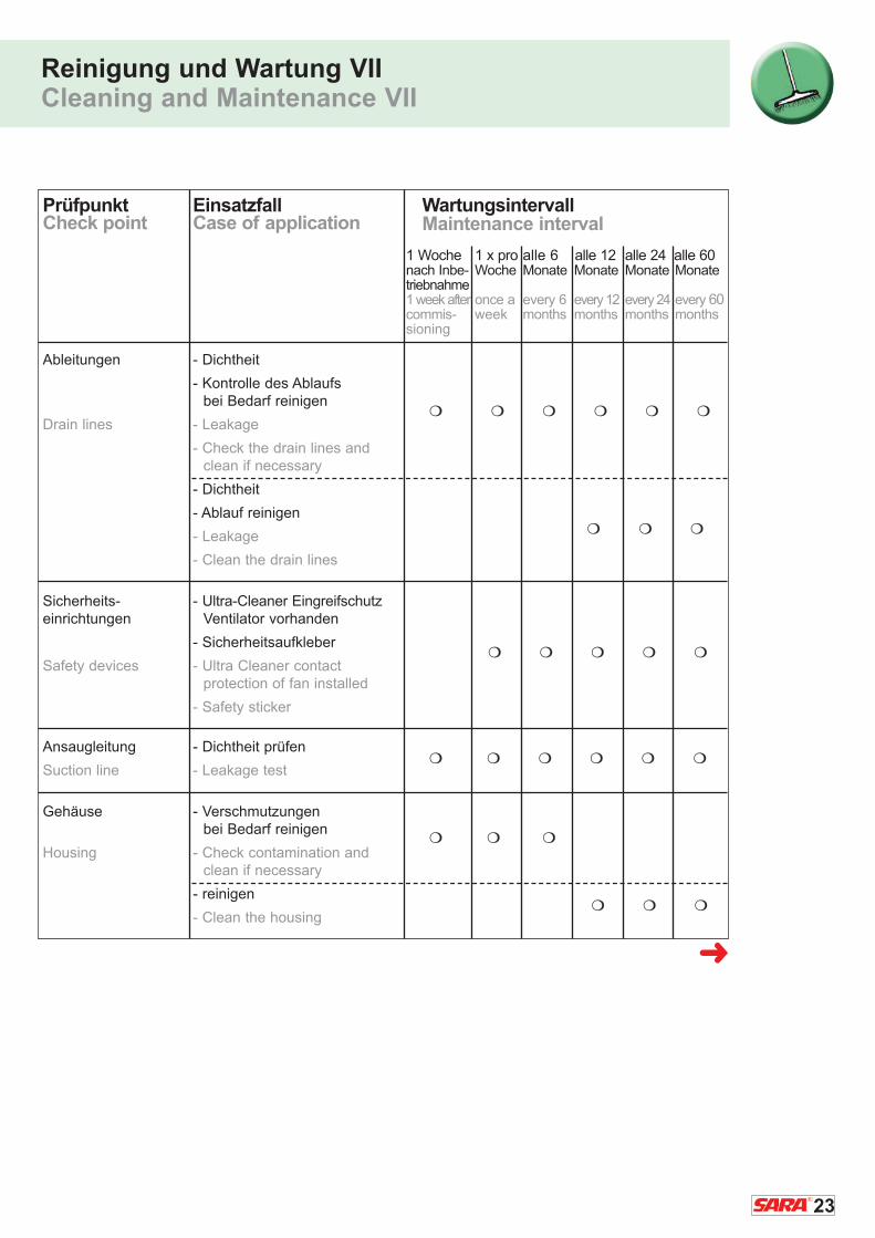
Prüfpunkt Einsatzfall WartungsintervallCheck point Case of application
Ableitungen - Dichtheit
- Kontrolle des Ablaufs bei Bedarf reinigen
Drain lines - Leakage
- Check the drain lines and clean if necessary
- Dichtheit
- Ablauf reinigen
- Leakage
- Clean the drain lines
Sicherheits- - Ultra-Cleaner Eingreifschutzeinrichtungen Ventilator vorhanden
- Sicherheitsaufkleber
Safety devices - Ultra Cleaner contactprotection of fan installed
- Safety sticker
Ansaugleitung - Dichtheit prüfen
Suction line - Leakage test
Gehäuse - Verschmutzungen bei Bedarf reinigen
Housing - Check contamination and clean if necessary
- reinigen
- Clean the housing
1 Woche 1 x pro alle 6 alle 12 alle 24 alle 60nach Inbe- Woche Monate Monate Monate Monatetriebnahme1 week after once a every 6 every 12 every 24 every 60commis- week months months months monthssioning
� � � � � �
� � �
� � � � �
� � � � � �
� � �
� � �
�
Maintenance interval
24
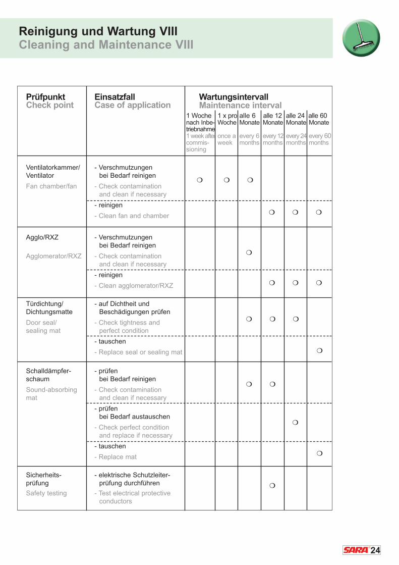
Reinigung und Wartung VIIICleaning and Maintenance VIII
Prüfpunkt Einsatzfall WartungsintervallCheck point Case of application
Ventilatorkammer/ - Verschmutzungen Ventilator bei Bedarf reinigen
Fan chamber/fan - Check contamination and clean if necessary
- reinigen
- Clean fan and chamber
Agglo/RXZ - Verschmutzungenbei Bedarf reinigen
Agglomerator/RXZ - Check contamination and clean if necessary
- reinigen
- Clean agglomerator/RXZ
Türdichtung/ - auf Dichtheit undDichtungsmatte Beschädigungen prüfen
Door seal/ - Check tightness and sealing mat perfect condition
- tauschen
- Replace seal or sealing mat
Schalldämpfer- - prüfen schaum bei Bedarf reinigen
Sound-absorbing - Check contamination mat and clean if necessary
- prüfen bei Bedarf austauschen
- Check perfect conditionand replace if necessary
- tauschen
- Replace mat
Sicherheits- - elektrische Schutzleiter-prüfung prüfung durchführen
Safety testing - Test electrical protectiveconductors
1 Woche 1 x pro alle 6 alle 12 alle 24 alle 60nach Inbe- Woche Monate Monate Monate Monatetriebnahme1 week after once a every 6 every 12 every 24 every 60commis- week months months months monthssioning
� � �
� � �
�
� � �
� � �
�
� �
�
�
�
Maintenance interval

25
Reinigung und Wartung IXCleaning and Maintenance IX
Prüfpunkt geprüft am geprüft am geprüft am
Datum/Unterschrift Datum/Unterschrift Datum/Unterschrift
Check point Checked on Checked on Checked ondate/signature date/signature date/signature
Ableitungen
Drain lines
Sicherheits-einrichtungen
Safety devices
Ansaugleitung
Suction line
Gehäuse
Housing
Ventilatorkammer/Ventilator
Fan chamber/fan
Agglo/RXZ
Agglomerator/RXZ
Türdichtung/Dichtungsmatte
Door seal/sealing mat
Schalldämpfer-schaum
Sound-absorbingmat
Sicherheits-prüfungSafetytesting �
Serien Nummer: / Serial Number:
26
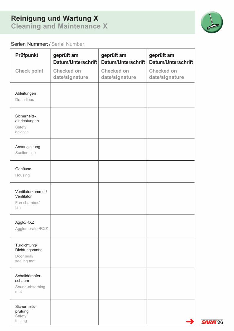
Reinigung und Wartung XCleaning and Maintenance X
Prüfpunkt geprüft am geprüft am geprüft am
Datum/Unterschrift Datum/Unterschrift Datum/Unterschrift
Check point Checked on Checked on Checked ondate/signature date/signature date/signature
Ableitungen
Drain lines
Sicherheits-einrichtungen
Safety devices
Ansaugleitung
Suction line
Gehäuse
Housing
Ventilatorkammer/Ventilator
Fan chamber/fan
Agglo/RXZ
Agglomerator/RXZ
Türdichtung/Dichtungsmatte
Door seal/sealing mat
Schalldämpfer-schaum
Sound-absorbingmat
Sicherheits-prüfungSafetytesting �
Serien Nummer: / Serial Number:

27
Reinigung und Wartung XICleaning and Maintenance XI
Prüfpunkt geprüft am geprüft am geprüft am
Datum/Unterschrift Datum/Unterschrift Datum/Unterschrift
Check point Checked on Checked on Checked ondate/signature date/signature date/signature
Ableitungen
Drain lines
Sicherheits-einrichtungen
Safety devices
Ansaugleitung
Suction line
Gehäuse
Housing
Ventilatorkammer/Ventilator
Fan chamber/fan
Agglo/RXZ
Agglomerator/RXZ
Türdichtung/Dichtungsmatte
Door seal/sealing mat
Schalldämpfer-schaum
Sound-absorbingmat
Sicherheits-prüfungSafetytesting
Serien Nummer: / Serial Number:
�
28
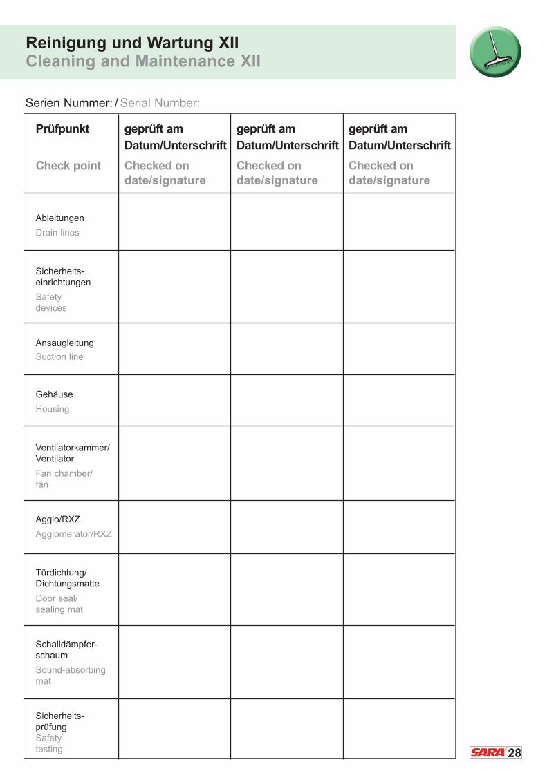
Reinigung und Wartung XIICleaning and Maintenance XII
Prüfpunkt geprüft am geprüft am geprüft am
Datum/Unterschrift Datum/Unterschrift Datum/Unterschrift
Check point Checked on Checked on Checked ondate/signature date/signature date/signature
Ableitungen
Drain lines
Sicherheits-einrichtungen
Safety devices
Ansaugleitung
Suction line
Gehäuse
Housing
Ventilatorkammer/Ventilator
Fan chamber/fan
Agglo/RXZ
Agglomerator/RXZ
Türdichtung/Dichtungsmatte
Door seal/sealing mat
Schalldämpfer-schaum
Sound-absorbingmat
Sicherheits-prüfungSafetytesting
Serien Nummer: / Serial Number:

29
Ersatzteilliste ISpare Parts List I
Ersatzteilliste Ultra Cleaner /S3 / Spare parts for the Ultra Cleaner /S3
Art.-Nr. / Part No. Bezeichnung / Description passend zu / suitable for
9020501080 Vorfilter / Prefilter UC1SD/S3 + UC2SD/S3
9020501090 Vorfilter / Prefilter UC3SD/S3
9090050002 Siphon / Siphon alle Modelle / all models
9090050004 Anschluss für ÖlrückführschlauchConnection for oil return hose alle Modelle / all models
9090050030 Schwebstofffilteraufsatz (inkl. Kassette)
Submicron particulate filter top unit 550x335x350mm UC1SD/S3
9090050031 Schwebstofffilteraufsatz (inkl. Kassette)
Submicron particulate filter top unit 590x415x350mm UC2SD/S3
9090050032 Schwebstofffilteraufsatz (inkl. Kassette)
Submicron particulate filter top unit 630x495x350mm UC3SD/S3
9090050007 Ersatz-Schwebstofffilterkassette Spare submicron particulate filter cartridgeDIN24184 / EN 1822 UC1SD/S3
9090050017 Ersatz-Schwebstofffilterkassette Spare submicron particulate filter cartridgeDIN24184 / EN 1822 UC2SD/S3
9090050008 Ersatz-Schwebstofffilterkassette Spare submicron particulate filter cartridgeDIN24184 / EN 1822 UC3SD/S3
9090050026 Schalldämpfereinsatz Sound absorber insert UC1SD/S3
9090050027 Schalldämpfereinsatz Sound absorber insert UC2SD/S3
9090050028 Schalldämpfereinsatz Sound absorber insert UC3SD/S3
Tel. +49 (0) 2102 / 44 00 - 0 · www.sartorius-werkzeuge.deFax. +49 (0) 2102 / 44 00 - 24 · [email protected]
�
(incl. cartridge)
(incl. cartridge)
(incl. cartridge)
30
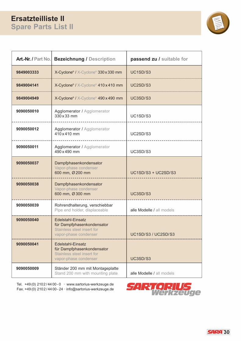
Ersatzteilliste IISpare Parts List II
Art.-Nr. / Part No. Bezeichnung / Description passend zu / suitable for
9849003333 X-Cyclone® / X-Cyclone® 330 x 330 mm UC1SD/S3
9849004141 X-Cyclone® / X-Cyclone® 410 x 410 mm UC2SD/S3
9849004949 X-Cyclone® / X-Cyclone® 490 x 490 mm UC3SD/S3
9090050010 Agglomerator / Agglomerator330 x 33 mm UC1SD/S3
9090050012 Agglomerator / Agglomerator410 x 410 mm UC2SD/S3
9090050011 Agglomerator / Agglomerator490 x 490 mm UC3SD/S3
9090050037 Dampfphasenkondensator Vapor-phase condenser600 mm, Ø 200 mm UC1SD/S3 + UC2SD/S3
9090050038 Dampfphasenkondensator Vapor-phase condenser600 mm, Ø 300 mm UC3SD/S3
9090050039 Rohrendhalterung, verschiebbar Pipe end holder, displaceable alle Modelle / all models
9090050040 Edelstahl-Einsatz für DampfphasenkondensatorStainless steel insert for vapor-phase condenser UC1SD/S3 / UC2SD/S3
9090050041 Edelstahl-Einsatz für DampfphasenkondensatorStainless steel insert for vapor-phase condenser UC3SD/S3
9090050009 Ständer 200 mm mit MontageplatteStand 200 mm with mounting plate alle Modelle / all models
Tel. +49 (0) 2102 / 44 00 - 0 · www.sartorius-werkzeuge.deFax. +49 (0) 2102 / 44 00 - 24 · [email protected]
31
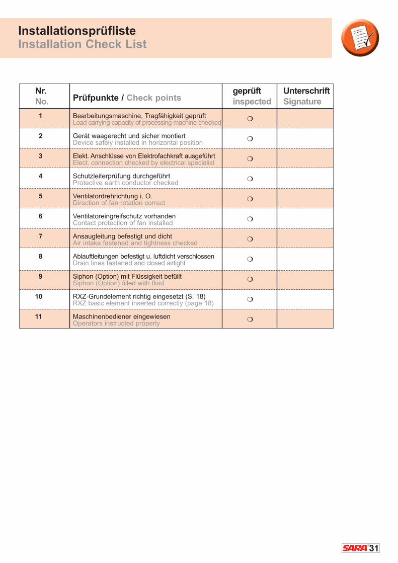
Prüfpunkte / Check points
1 Bearbeitungsmaschine, Tragfähigkeit geprüftLoad carrying capacity of processing machine checked.
2 Gerät waagerecht und sicher montiertDevice safely installed in horizontal position
3 Elekt. Anschlüsse von Elektrofachkraft ausgeführtElect. connection checked by electrical specialist
4 Schutzleiterprüfung durchgeführtProtective earth conductor checked
5 Ventilatordrehrichtung i. O.Direction of fan rotation correct
6 Ventilatoreingreifschutz vorhandenContact protection of fan installed
7 Ansaugleitung befestigt und dichtAir intake fastened and tightness checked
8 Ablauftleitungen befestigt u. luftdicht verschlossenDrain lines fastened and closed airtight
9 Siphon (Option) mit Flüssigkeit befülltSiphon (Option) filled with fluid
10 RXZ-Grundelement richtig eingesetzt (S. 18)RXZ basic element inserted correctly (page 18)
11 Maschinenbediener eingewiesenOperators instructed properly
InstallationsprüflisteInstallation Check List
Nr.No.
UnterschriftSignature
geprüft inspected
�
�
�
�
�
�
�
�
�
�
�

32
HerstellererklärungManufacturer’s Declaration
Än
de
run
ge
n u
nd
Irr
tüm
er
vorb
eh
alte
n!
Su
bje
ct t
o c
ha
ng
e w
itho
ut
no
tice
! E
rro
rs e
xce
pte
d!
EG-Konformitätserklärung im Sinne der Maschinenrichtlinie 2006/42/EG
Die Bauart der Geräte:
- X-Cyclone®-Ölnebelabscheider - Kanalabscheider RK - Abscheideköpfe R-1S, R-2S
- Ultra Cleaner UC - Kanalabscheider RKM
wurde in Übereinstimmung mit den
EG-Richtlinien 2006/42/EG entwickelt,
konstruiert und gefertigt in alleiniger
Verantwortung von:
Folgende harmonisierte Normen wurden angewandt:
EN ISO 13857, EN ISO 13850, EN ISO 12100 T1-T2, EN 953, EN 60204-T1, EN 563,
EN 626 T1-T2, EN 626 T1-T2, EN 1005 T1-T2, EN 12437 T1-T4
ACHTUNG:
� Die Einhaltung der EG-Richtlinie 2006/42/EG bezieht sich nur dann auf dieses Produkt,
wenn es eigenständig betrieben wird und die Maschinenrichtlinien beachtet und eingehalten
werden. Wird dieses Produkt in eine Anlage integriert oder mit anderen Komponenten
komplettiert und betrieben, so ist der Hersteller oder Betreiber der Gesamtanlage für
die Einhaltung der Maschinenrichtlinien verantwortlich.
Declaration of Conformity with EC Directives as defined by theMachinery Directive 2006/42/EG
The types of machinery:
- X-Cyclone® oil mist separator - Duct separator RK - Separator heads R-1S, R-2S
- Ultra Cleaner UC - Duct separator RKM
have been developed, designed and
manufactured in compliance with the
requirements of the EC directives
2006/42/EG, at the sole responsibility of:
The following harmonized standards apply:
EN ISO 13857, EN ISO 13850, EN ISO 12100 T1-T2, EN 953, EN 60204-T1, EN 563,
EN 626 T1-T2, EN 626 T1-T2, EN 1005 T1-T2, EN 12437 T1-T4
ATTENTION:
� The compliance with the EC directive 2006/42/EG refers only to this product if it is
operated independently and if the requirements of the Machinery Directives are
respected and adhered to. If this product is integrated into a plant or is supplemented
with other components for operation, the supplying or operating company of the total
plant is responsible for the compliance with the Machinery Directives.
Rentschler Reven®
Lüftungssysteme GmbHLudwigstrasse 16-18D – 74372 SersheimGermany
www.reven.de
Rentschler Reven®
Lüftungssysteme GmbHLudwigstrasse 16-18D – 74372 Sersheim
www.reven.de