Be Beam Pipe Design - SLAC
14
Be Beam Pipe Design Knut Skarpaas VIII 6/16/06
Transcript of Be Beam Pipe Design - SLAC

Be Beam Pipe Design
Knut Skarpaas VIII6/16/06

My Background on this subject-
Came to SLAC 1993 to do the mechanical design of VXD3 and it’s associated Beam Pipe for SLD
(SLD used a gas cooled pipe with a working temp of 160K)Studied past Vertex Detectors and beam pipes for this design
Designed the Beam Pipe which BaBar currently usesStudied Be corrosion and Be part failure to understand problem
Water cooled Beryllium, high radiation, high currentDesigned 1996-1997, fabbed and installed shortly thereafter
- still under water with no leaks

Design challenges-
High heat load – designed for about 1KwWater deemed necessary for heat loadSignificant effort made to avoid corrosion
High radiation dose – 1Mega rad min. with up to 100Mega rad possible
Dose is high for most plastics

Corrosion protection-Beryllium and water typically are not a good mix
An initial CLEO pipe failed before installation due to a drop of cooling fluid that dripped on it from a CMM. I was told that the ethylene glycol mix bored a hole in the pipe over night.
There should be no brazes in the water path-Electrofusion mentioned that the flux used to braze Be gets activated by water and is quite corrosive.
For the BaBar pipe, I used many levels of protection-Level 1- Use BR154 paint to keep water off the metal (phenolic polymer barrier)Level 2- BR 154 contains strontium chromate which is a corrosion inhibitor (anodic protection)Level 3- Layer two of BR154 (pinholes in layer one should not align with pinholes in layer two)Level 4- Electroless Ni plating of all Be areas exposed to waterLevel 5- Beryllium used was a special grade of Be which has low carbon content (Carbon
forms are used while compressing the raw Be block. Carbon particles are sites for corrosive galvanic cells on the Be surface)
Level 6- A low conductivity water is used which inhibits corrosionLevel 7- Water system is sub-atmospheric (it will suck air before killing the SVT)
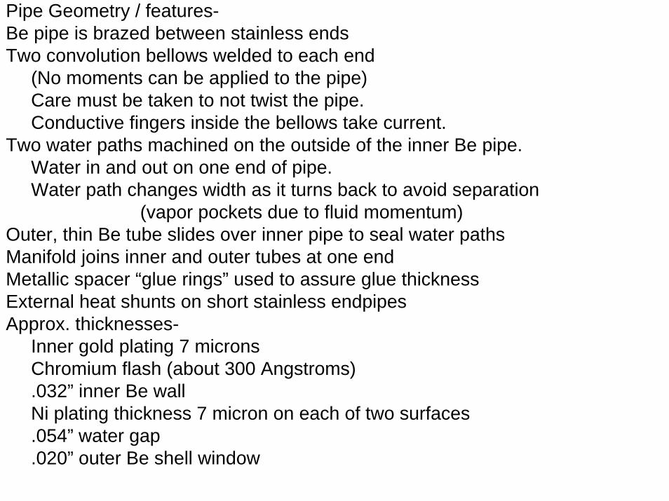
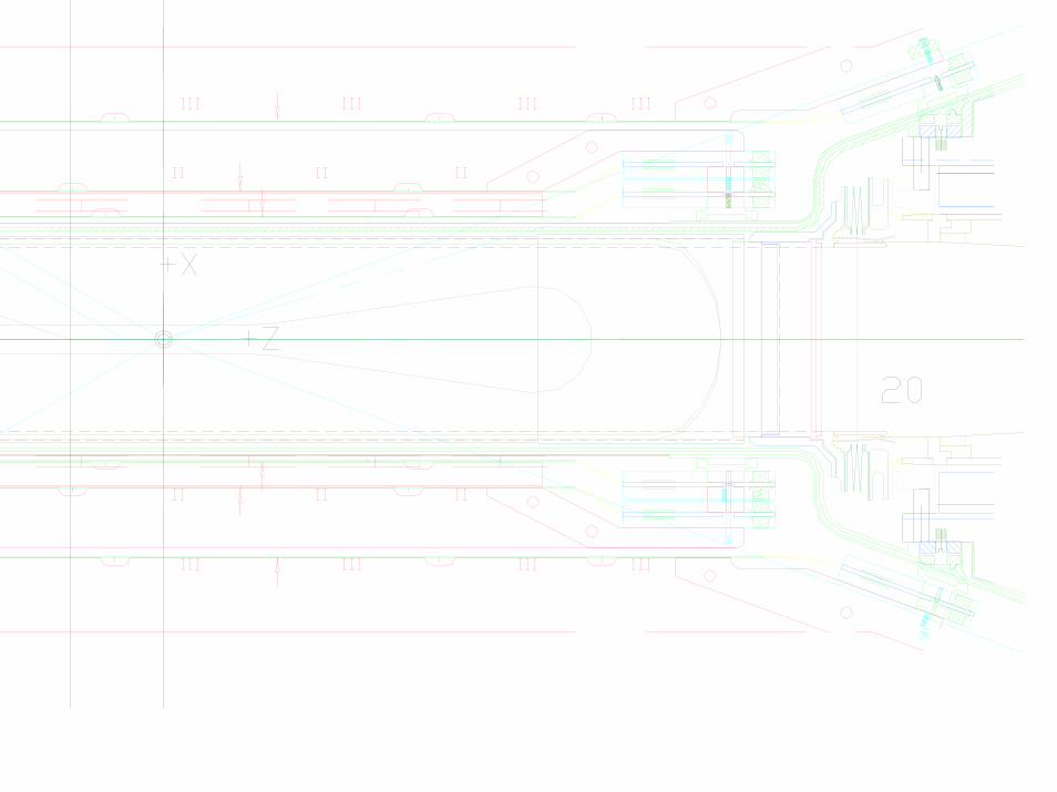
Pipe Geometry / features-Be pipe is brazed between stainless endsTwo convolution bellows welded to each end
(No moments can be applied to the pipe)Care must be taken to not twist the pipe.Conductive fingers inside the bellows take current.
Two water paths machined on the outside of the inner Be pipe.Water in and out on one end of pipe.Water path changes width as it turns back to avoid separation
(vapor pockets due to fluid momentum) Outer, thin Be tube slides over inner pipe to seal water pathsManifold joins inner and outer tubes at one endMetallic spacer “glue rings” used to assure glue thicknessExternal heat shunts on short stainless endpipesApprox. thicknesses-
Inner gold plating 7 micronsChromium flash (about 300 Angstroms) .032” inner Be wallNi plating thickness 7 micron on each of two surfaces.054” water gap.020” outer Be shell window