Klystron Cluster RF Distribution Scheme Chris Adolphsen Chris Nantista SLAC.

A SHEET-BEAM KLYSTRON PAPER DESIGN
G. CaryotakisStanford Linear Accelerator Center, Stanford University, Stanford Ca. 94309
AbstractWhat may be the first detailed cold test and computer simulation analysis ofa Double Sheet Beam Klystron (DSBK) was performed at SLAC. Thedevice was conceptually designed mechanically, and evaluated electricallyfor beam formation, gain, stability and efficiency. It is believed that theDSBK can be built at a relatively low cost for a future NLC collider and canproduce at least 150 MW at 11.4 GHz with PPM focusing. Voltage andcurrent are 450 kV and 640 A, respectively.
The Sheet Beam Klystron (SBK) is a device that has been considered as a microwave source for atleast 60 years, but has never been fully designed or constructed. It was first proposed by Kovalenkoin Russia in 1938 and revisited repeatedly over the years in the USSR, France and the US. The factthat no serious attempt was ever made to build and test an SBK can probably be attributed to theexistence of alternatives and to perceived electrical and mechanical difficulties.
The principal electrical difficulties have been the large drift tube and overmoded cavities thatthe SBK requires. Also, designers have been concerned with the possibility that the sheet beam mightbe unstable suffering from diocotron break-up, or be difficult to contain laterally at the edges.Mechanical issues centered mostly at the gun, and the thermal design of a large cathode/heaterpackage. Certainly, the construction of sheet-beam guns is beyond the capabilities of mostuniversities and national laboratories. Industry, for the most part, has not taken on the SBK designproblem, simply because other klystron types could serve existing requirements, or could be easilydeveloped.
The chief virtue of the SBK is that its large lateral dimensions permit high power to be attainedwith low current densities in the cathode, and low power concentration in the cavities. This is thesame advantage that multiple beam klystrons have over single-beam klystrons. The difference is thatan SBK can be made with a fraction of the parts an MBK requires, or for that matter, that arenormally used in an ordinary klystron.
At SLAC, the logistics of the Next Linear Collider (NLC) initially required several thousand75-MW X-band klystrons for the 500 GeV versions of the machine. Gradually, as these tubes werebuilt, put to use, and accumulated hours, confidence in their performance led to increases in the pulselength and the ratio of pulse compression. Today, the baseline NLC klystron has a pulse length ofapproximately 3 microseconds and the number of PPM-focused klystrons is approximately 1600.Obviously, this is still a large number of fairly complicated tubes. A klystron with twice the outputwould be very desirable, especially if a 1-TeV NLC were to be considered. However, 150 MW peakand a 50 kW average power at 11.4 GHz is uncomfortably high with a single beam and an outputcircuit with a one-centimeter bore. This is what motivated us to look very seriously into the SBK.
Through a process of parameter trade-offs, the design that has emerged employs two beams,each with an aspect ratio of 10:1 and perveance of 1.1 x 10 -6 (0.11 micropervs per square). These areconservative numbers, and they are, in part, dictated by the necessity to use periodic focusing and toplace magnets and polepieces at some distance from the beams in order to simplify the mechanicaldesign and allow water-cooling in the space between the circuit and the magnet stack.
SLAC-PUB-8967
5th Modulator-Klystron Workshop for Future Linear Colliders
(MDK-2001)
CERN, PS Division, Geneva, 26-27 April 2001
Work supported by the Department of Energy contract DE-AC03-76SF00515.

As a matter of fact, mechanical considerations formed the basis for the overall design of thisDSBK (Double Sheet Beam Klystron). Referring to Figs. 1 and 2, it can be seen that the cavities, drifttunnels and collectors are fabricated on numerically controlled machines out of four (4) slabs ofcopper. The two klystrons making up the DSBK share the same vacuum plenum at the double gun,but are otherwise separate mechanically and electrically. The two halves of each klystron areseparated by a fraction of a millimeter so that cavities and drift tubes can be pumped from vacuummanifolds running along the entire length of the rf sections and the collectors. This is possiblebecause the TM modes in the cavities do not have rf currents crossing the surface where the twohalves are separated. (The guns are shown gridded because the picture was drawn for a differentversion of the DSBK).
Fig. 1
Fig. 2

These are twin 5-cavity klystrons, with all cavities of the extended type operating in the „-mode. The paper design consisted of a number of simulations and some cold testing. We wished toverify the following go, no-go conditions:
1. A gun can be designed with the necessary convergence and a low cathode current density.
2. The beam is well behaved and does not spread excessively laterally.
3. Cavities with sufficiently good R/Q and coupling coefficient can be designed, and provide areasonably uniform field across the beam.
4. The klystron has good gain and efficiency.
5. The cavities are free of monotron oscillations for TM modes.
These were the conditions that had to be satisfied before prototype construction is attempted.Results are shown in the figures that follow.
Fig. 3
1. Figure 3 shows a MAGIC 3D simulation of a gun which provides a beam 8-mmthick, 8-cm wide, with a beam current density of 50 A/cm2, and an area convergence of 10, i.e.a cathode current density of 5 A/cm2. The cathode surface is elliptical for good optics.
2. Lateral gun electrodes have not been designed as yet, but Fig. 4 shows that a beamartificially injected in the drift tunnel and immersed in a 3000 magnetic field is not spreading ina 10-cm distance and remains evenly distributed along its width. PPM simulations have notbeen performed as of yet, but PPM focusing is not expected to be a problem.
3. The cavities for the DSBK were at first designed as single cutoff waveguides. This is the method proposed at SLAC more than 15 years ago for providing a flat electric field across the width of the beam. A cold test model was constructed to test this scheme, as well as the
isolation between cavities separated by varying lengths of a 1.2 x 9 cm drift tunnel (Fig.5)Cavity isolation was found to be more than 50 db in 5 cm of drift tube. However, GdfidL andMAGIC calculations showed that the coupling coefficient and R/Q were too low for a singlecavity of the cutoff waveguide type. Figure 6 shows that the coupling coefficient for a transitangle of about 1 radian was only 0.09. Using triplet cutoff waveguides coupled capacitively

through the drift tube and operating in the „ mode corrected this. The coupling coefficientincreased to 0.36 with an R/Q of 52 ohms. The light spots in the middle of the top view of thebeam (Fig. 4) are a printer artifact.
Fig. 4
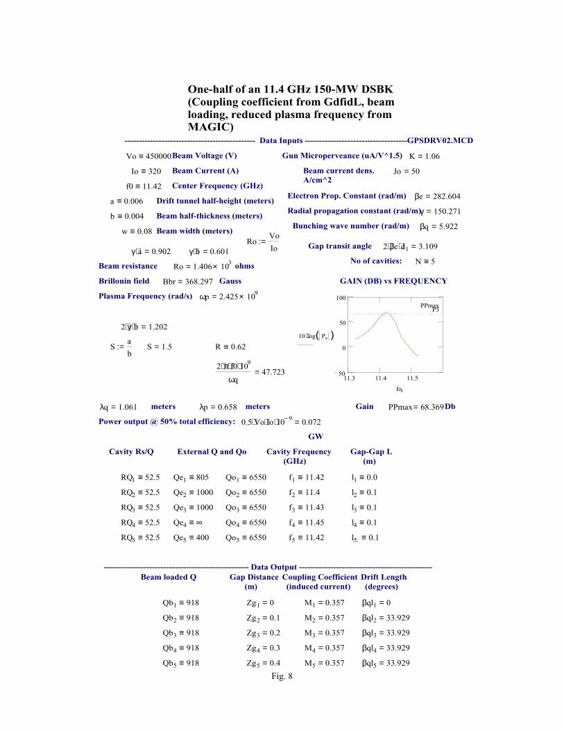
4. With two of these cavities and an artificial beam, a MAGIC calculation produced a gain ofabout 18 db between two triplets spaced about 30 cm apart. Figure 7 shows the ratio of the rfcurrent induced in the second cavity to the artificial rf current in the beam exciting the firstcavity. We have inferred from these simulations the reduced plasma wavelength and beamloading parameters necessary to calculate small-signal gain. Using these in a standard gainvs. frequency calculation, we predict a 68+ db gain for the 5-cavity tube (Fig. 8 is on aseparate page). Finally, a large-signal 3D-MAGIC simulation (Fig. 9) was run in which abeam modulated with an I1/I0 of 1 drives a triplet. The figure shows normal debunching, andFigure 10 indicates that this is evenly distributed across the width of the beam. A simulationfor a higher value of I1/Io will follow.
Fig. 5

Single Cavity M = 0.088
SBK Field Profile
-1.0E+08
-5.0E+07
0.0E+00
5.0E+07
1.0E+08
1.5E+08
-0.05
-0.04
-0.03
-0.02
-0.01
0.00
0.01
0.02
0.03
0.04
0.05
Z
Ez
-3.0E+06
-1.5E+06
0.0E+00
1.5E+06
3.0E+06
4.5E+06
Inte
gra
l{E
z.d
z}
EzEz*CosineIntegral{Ez*dz}Integral{Ez*Cosine*dz}
Triple Cavity M = 0.36
SBK Field Profile
-0.5
-0.4
-0.3
-0.2
-0.1
0.0
0.1
0.2
0.3
0.4
0.5
-0.05
-0.04
-0.03
-0.02
-0.01
0.00
0.01
0.02
0.03
0.04
0.05
Z
Ez
-0.015
-0.010
-0.005
0.000
0.005
0.010
0.015
Inte
gra
l{E
z.d
z}
EzEz*CosineIntegral{|Ez|*dz}Integral{Ez*Cosine*dz}
Fig. 6
Fig. 7. RF current vs. Z.

Fig. 9
Fig. 10
Qe5 400≡RQ5 52.5≡
l4 0.1≡f4 11.45≡Qo4 6550≡Qe4 ∞≡RQ4 52.5≡
l3 0.1≡f3 11.43≡Qo3 6550≡Qe3 1000≡RQ3 52.5≡
l2 0.1≡f2 11.4≡Qo2 6550≡Qe2 1000≡RQ2 52.5≡
l1 0.0≡f1 11.42≡Qo1 6550≡Qe1 805≡RQ1 52.5≡
Gap-Gap L (m)
Cavity Frequency (GHz)
External Q and QoCavity Rs/Q
GW
βql5 33.929=M5 0.357=Zg5 0.4=Qb5 918≡
βql4 33.929=M4 0.357=Zg4 0.3=Qb4 918≡
βql3 33.929=M3 0.357=Zg3 0.2=Qb3 918≡
βql2 33.929=M2 0.357=Zg2 0.1=Qb2 918≡
βql1 0=M1 0.357=Zg1 0=Qb1 918≡
Drift Length (degrees)
Coupling Coefficient (induced current)
Gap Distance (m)
Beam loaded Q --------------------------------------------------- Data Output -----------------------------------------------
l5. 0.1≡f5 11.42≡Qo5 6550≡
2 βe⋅ d1⋅ 3.109=Gap transit angleRoVo
Io:=
Beam width (meters)w 0.08≡ βq 5.922=Bunching wave number (rad/m)Beam half-thickness (meters)b 0.004≡ γ 150.271=Radial propagation constant (rad/m)Drift tunnel half-height (meters)a 0.006≡ βe 282.604=Electron Prop. Constant (rad/m)
Center Frequency (GHz)f0 11.42≡
Jo 50=Beam current dens.A/cm^2
Beam Current (A)Io 320≡
K 1.06=Gun Microperveance (uA/V^1.5)Beam Voltage (V)Vo 450000≡
---------------------------------------------- Data Inputs ------------------------------------GPSDRV02.MCD
One-half of an 11.4 GHz 150-MW DSBK(Coupling coefficient from GdfidL, beam loading, reduced plasma frequency from MAGIC)
0.5 Vo⋅ Io⋅ 10 9−⋅ 0.072=Power output @ 50% total efficiency:
DbPPmax 68.369=Gainmetersλp 0.658=metersλq 1.061=
2 π⋅ f0⋅ 109⋅
ωq47.723=
R 0.62≡S 1.5=Sa
b:=
2 γ⋅ b⋅ 1.202=
ωp 2.425 109×=Plasma Frequency (rad/s)
11.3 11.4 11.550
0
50
100
P3PPmax
10 log Ps( )⋅
fos
GAIN (DB) vs FREQUENCY GaussBbr 368.297=Brillouin field
ohmsRo 1.406 103×=Beam resistance N 5≡No of cavities:γ b⋅ 0.601=γ a⋅ 0.902=
Fig. 8

0
1
2
3
4
5
6
7
9.000 10.000 11.000 12.000 13.000 14.000 15.000
Frequency [GHz]
Mod
e N
umbe
r for
Bea
m W
idth
"+ + +""+ 0 -""+ - +"
N=4, +++ mode
N "+ + +" "+ 0 -" "+ - +"0 9.245 10.502 11.5421 9.598 10.762 11.6892 10.143 11.152 11.9303 10.817 11.575 12.2924 11.588 12.193 12.8275 12.358 12.876 13.4976 13.129 13.558 14.394
Fig. 11
5. To test for stability in unloaded triplet cavities, a mode search was conducted using MAGIC(Fig. 11), and several of the TM modes were tested for negative beam loading, using GdfidLand the M2
minus — M2plus criterion, the difference between the squares of the coupling
coefficients for the fast and the slow space charge waves. (See Fig. 12). The slight differencesin the frequencies between Fig. 12 and mode search and the stability tests in Fig. 12, are dueto the fact that the structure used in Fig. 12, was tuned at 11.426 GHz, instead of 11.542 GHz.

Beam Couplingpi-mode 11.4226
0 50 100 150 200 250 300 350 400
0
0.1
.2
.1
βei
Mminusi
2Mplus
i2.
8 βq.
350.3210.017 Vbi
+0- mode N=0 and 2, 10.5203 and 11.2096
0 50 100 150 200 250 300 350 400
0
0.1
.2
.1
βei
Mminusi
2Mplus
i2.
8 βq.
350.3210.017 Vbi
+++ mode N=4, 11.5735
0 50 100 150 200 250 300 350 400
0
0.1
.2
.1
βei
Mminusi
2Mplus
i2.
8 βq.
350.3210.017 Vbi
Fig. 12 Stability test examples

CONCLUSIONS
Although additional simulations will be necessary, it is clear the device has an excellent chance towork and should be built. This may take place in 2002.

APPENDIX 1 — LATE BREAKING RESULTS FROM MRC
Some recent results arrived from MRC which were too late to incorporate into the body of the paper,but too important to leave out. The first transmission from Dave Smithe of MRC, who was asked todrive a triplet cavity with a fully pre-bunched beam, is reproduced here without comment except tonote that this is the first effort to run the simulation for full power. No attempts have been made totune or otherwise adjust for maximum power.
A.1.1 OUTPUT POWER
Geometry: Resistive load filling each of the end cells.
Beam voltage = 450 kV, Beam current = 320 amps, I1/I0 = 1.8.
Output Power: 62.0 MWatts,Wall Losses: 5.5 MWatts
A top view of the cavity geometry is shown in Fig. A.1.1.1. There is resistive load in each of the endcells.
Fig. A.1.1.1
A pre-bunched beam is injected into the cavity, and it is rung up to saturation. Many runs weredone to optimize the output power by varying the amount of resistance (cavity Q), and hot-testfrequency-shift (+0.01%). The following figure (A.1.1.2) shows the time-history of cavity saturation.The first plot shows the sum of power to the end-cell load plus wall-losses, and the second plot showsjust wall-losses.
Load + Wall Losses Just Wall Losses
Fig. A.1.1.2

A view of the particles and current is shown below (Fig. A.1.1.3). The shape of the pre-bunchedcurrent is a sine wave, truncated below some value, and re-scaled to give the correct DC current. Theparticles are injected at a single energy of 450 kV.
Fig. A.1.1.3

Shown below are views of particle-energy, average-energy-per-particle, and RF-current, down thelength of the drift tube (Fig. A.1.1.4). Note that few, if any, particles are turned-around. About 47%of the original beam energy is lost, 43% to the output load, and 4% to copper wall losses. The RFcurrent at the exit is about _ of the original pre-bunched RF current.
Particle Energy
Average Particle Energy
RF Currrent
Fig. A.1.1.4

A.1.2 TEST OF CAVITY STABILITY
This is a final transmission from MRC (Fig. A.1.2.1). The objective here was to completelyunbalance the beam to see whether modes might be excited in the cavity that would lead tooscillations. It can be seen from the treatment below that this did not happen.
Geometry: Unloaded, copper cavity.
Used _ of beam, e.g., missing right and lower halves, with no RF signal, other than the initialtransient. The offset beam and the initial transient provide the seed for any unstable modes. Thebeam current density is the save as for the previous 450 kV, 320 amp runs.
Fig. A.1.2.1

From previous simulations, it is already known that the system is stable at the operating mode,as the operating mode has been to seen to saturate in a conventional manner during small-signalanalysis.
The simulation was run for 80 nanoseconds. Any linear instability would exhibit anexponential increase in the electromagnetic energy (Uem= _ε|E|2 + _µ|H|2 ) stored within the cavity, asthe instability mode grew in amplitude. No such increase was observed. The offset beam, in both Xand Y directions, should couple strongly to virtually all conceivable modes, thus there is little chancethat an instability exists, but is undetected, since the instability seed is quite strong.
Wall losses of copper have been included. Thus it is still possible that a perfectly conductingcavity might experience an instability, but that the copper wall-loss loaded system is stable.
Instead of an exponential rise in EM energy, a very slow, approximately linear, growth inelectromagnetic energy was observed (Fig. A.1.2.2). This is typical of all unfiltered relativisticparticle-in-cell simulations and is associated with growth of short-wavelength (grid-size) particlenoise in a simulation. There is no identifiable cavity mode structure associated with particle noise(Fig. A.1.2.3).
EM Energy in Cavity
Fig. A.1.2.2
There is also no evidence of a coherent RF signal on the particle positions or energy after 80nanoseconds.
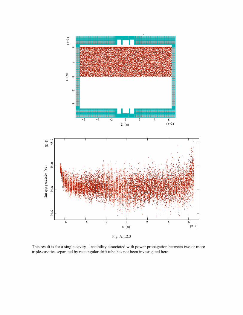
Fig. A.1.2.3
This result is for a single cavity. Instability associated with power propagation between two or moretriple-cavities separated by rectangular drift tube has not been investigated here.

ACKNOWLEDGEMENTS
Thanks are due to Daryl Sprehn, who developed the gun optics, Mike Neubauer for the GdifdLsimulations, David Smithe of MRC who performed the MAGIC simulations, and Randy Fowkes forthe cold test work.