BDA Agrément BAF 16-059/01/A - Precast Concrete · BDA Agrément ® BAF 16-059/01/A Date...
12
Number BAF 16-059/01/A Replaces: - BDA Agrément ® BAF 16-059/01/A Date 2016-10-10 Category Insulated suspended concrete ground floors Phase Assessment Systems Agrément holder Description Scope (use) Objective Summary of Agrément Major points of assessment Statement Gdeck EPS Panel System Combined Thermal Solutions (CTS) Hawtin Park T. : +44 (0)1443 441 491 Gellihaf, Blackwood E. : [email protected] Caerphilly, NP12 2EU, UK W. : www.combinedthermalsolutions.co.uk Flooring insulation system comprising a range of expanded polystyrene (EPS) infill blocks and load bearing rails for use as thermal insulation in conjunction with (but not manufactured by the Agrément holder) structural concrete toppings, precast concrete beams, masonry closure and coursing blocks in suspended concrete ground floors (over a sub floor void). Thermal insulation for use in the building envelope in domestic, residential and commercial buildings, designed and constructed in accordance with the relevant clauses of this Agrément and the Agrément holder’s requirements. See also section 3 of this document for the full range of Gdeck EPS Panel System. This document provides independent information to specifiers, building control personnel, contractors, installers and other construction industry professionals with regard to the fitness for the intended use of the Systems. This Agrément covers the following: • Conditions of use; • Frame of reference, including codes of practice, test and calculation reports; • Independently assessed system characteristics and other system information; • Factory Production Control and annual verification procedure; • Points of attention for the specifier and examples of details; • Installation procedure; • Compliance with Building Regulations. Thermal performance aspects (sections 8.4, 8.5 & 8.6) The EPS infill blocks and load bearing rails can enable a floor to meet the design U values specified in the documents supporting the Building Regulations. Condensation and water (vapour) infiltration risk (section 8.7) The EPS infill blocks and load bearing rails can contribute to minimising the risk of interstitial and surface condensation in floors. Structural performance (sections 8.8.1 to 8.8.4) The system has adequate strength and stiffness to sustain and transmit dead and imposed floor loads in residential, domestic or commercial buildings. Durability (section 8.10) The EPS infill blocks and load bearing rails are stable, rot-proof and durable and will remain for the life of the building in which it is installed. It is the opinion of the Kiwa BDA Expert Centre Building Envelope (ECBE) that Gdeck EPS Panel System is fit for its intended use, provided it is specified, installed and used in accordance with this Agrément. Professor Nico Hendriks, MSc Authorization: Chris van der Meijden, MSc ECBE BDA Group Chairman Technical Director Version 01 Kiwa BDA Expert Centre Building Envelope (ECBE) BDA Group Kiwa Ltd. Avelingen West 33 Unit 5 Prime Park Way P.O. Box 389 Prime Enterprise Park 4200 AJ Gorinchem Derby, DE1 3QB The Netherlands United Kingdom +31 (0)183 66 96 90 +44 (0)7718 57 05 64 Copyright © 2016 Kiwa BDA www.kiwa.co.uk/bda Page 1 of 12 pages Project number 16-C-0247/2102 Validity www.kiwa.co.uk/bda Subject Thermal insulation systems
Transcript of BDA Agrément BAF 16-059/01/A - Precast Concrete · BDA Agrément ® BAF 16-059/01/A Date...
NumberBAF 16-059/01/A
Replaces:-
BDA Agrément® BAF 16-059/01/A
Date2016-10-10
CategoryInsulated suspendedconcrete ground floors
PhaseAssessment
Systems
Agrément holder
Description
Scope (use)
Objective
Summary of Agrément
Major points ofassessment
Statement
Gdeck EPS Panel System
Combined Thermal Solutions (CTS)Hawtin Park T. : +44 (0)1443 441 491Gellihaf, Blackwood E. : [email protected] Caerphilly, NP12 2EU, UK W.: www.combinedthermalsolutions.co.uk
Flooring insulation system comprising a range of expanded polystyrene (EPS) infill blocks and load bearing rails foruse as thermal insulation in conjunction with (but not manufactured by the Agrément holder) structural concrete toppings, precast concrete beams, masonry closure and coursing blocks in suspended concrete ground floors (over asub floor void).
Thermal insulation for use in the building envelope in domestic, residential and commercial buildings, designed and constructed in accordance with the relevant clauses of this Agrément and the Agrément holder’s requirements. See alsosection 3 of this document for the full range of Gdeck EPS Panel System.
This document provides independent information to specifiers, building control personnel, contractors, installers andother construction industry professionals with regard to the fitness for the intended use of the Systems.
This Agrément covers the following:• Conditions of use;• Frame of reference, including codes of practice, test and calculation reports;• Independently assessed system characteristics and other system information;• Factory Production Control and annual verification procedure;• Points of attention for the specifier and examples of details;• Installation procedure;• Compliance with Building Regulations.
Thermal performance aspects (sections 8.4, 8.5 & 8.6)The EPS infill blocks and load bearing rails can enable a floor to meet the design U values specified in the documentssupporting the Building Regulations.
Condensation and water (vapour) infiltration risk (section 8.7)The EPS infill blocks and load bearing rails can contribute to minimising the risk of interstitial and surface condensation in floors.
Structural performance (sections 8.8.1 to 8.8.4)The system has adequate strength and stiffness to sustain and transmit dead and imposed floor loads in residential,domestic or commercial buildings.
Durability (section 8.10)The EPS infill blocks and load bearing rails are stable, rot-proof and durable and will remain for the life of the buildingin which it is installed.
It is the opinion of the Kiwa BDA Expert Centre Building Envelope (ECBE) that Gdeck EPS Panel System is fit for itsintended use, provided it is specified, installed and used in accordance with this Agrément.
Professor Nico Hendriks, MSc Authorization: Chris van der Meijden, MSc
ECBE BDA Group Chairman Technical Director
Version01
Kiwa BDA Expert Centre Building Envelope (ECBE)BDA Group Kiwa Ltd.Avelingen West 33 Unit 5 Prime Park WayP.O. Box 389 Prime Enterprise Park 4200 AJ Gorinchem Derby, DE1 3QB The Netherlands United Kingdom +31 (0)183 66 96 90 +44 (0)7718 57 05 64
Copyright© 2016 Kiwa BDA www.kiwa.co.uk/bda
Page 1of 12 pages
Project number16-C-0247/2102
Validitywww.kiwa.co.uk/bda
SubjectThermalinsulationsystems
1 Conditions of use
2 Frame of reference
1 ApplicationThe assessment of Gdeck EPS Panel System relates to the use of the Systems in domestic, residential andcommercial buildings with correctly installed masonry external walls, which have been designed and constructed in accordance to BS EN 1996-1-1:2005+A1 and the UK NA to BS EN 1996-1-1:2005+A117,18
and correctly detailed ground floor systems, designed and constructed in accordance with BS 810220 andBS 821521 and with the Agrément holder’s requirements.
2 AssessmentKiwa BDA Expert Centre Building Envelope (ECBE) has assessed the thermal performance, design and installation of the product according to BS EN 15037-12, BS EN 15037-43 and BS EN 1996-1-1:2005+A117
and the UK NA to BS EN 1996-1-1:2005+A118 in combination with the DoP28 and Technical Assessmentand site visits. Also the NHBC Standards13 have been taken into account. Factory Production Control hasbeen assessed by Kiwa N.V., Technical Assessment Body, represented in the UK by Kiwa Ltd.27
3 Installation It is recommended that the quality of installation and workmanship is controlled by (a) competentperson(s). Such person(s) shall be either a qualified employee of the Agrément holder or a qualified employee of a consulting engineering body. The product shall be installed strictly in accordance with the requirements of the Agrément holder and the requirements of this Agrément.
4 Geographical scopeThe validity of this document is limited to England, Wales, Scotland and Northern Ireland, with due regardto section 11 Building Regulations.
5 ValidityThe purpose of this BDA Agrément® is to provide for well-founded confidence to apply Gdeck EPS PanelSystem in the described applications and according to approved specifications. According to the BDAGuideline - BDA Agrément®1 the validity of this Agrément is therefore three years after the official date ofissue, published on www.kiwa.co.uk/bda. After this the validity can be extended every three years afterpositive review. This Agrément is not valid in those cases where ECBE identifies that the design of a flooring system does not comply with article 8.2. Permitted constructions.
1 BDA Guideline - BDA Agrément®, 30th June 20152 BS EN 15037-1:2008 Precast concrete products. Beam-and-block floor systems. Beams3 BS EN 15037-4:2010+A1:2013 Precast concrete products. Beam-and-block floor systems. Expanded
polystyrene blocks4 BS EN 14889-2:2006 Fibres for concrete. Polymer fibres. Definitions, specifications and conformity5 BS EN 1990:2002+A1:2005 - Eurocode. Basis of structural design6 UK National Annex to BS EN 1990-20026
7 BS EN 1991-1-1:2002 - Eurocode 1: Actions on structures - Part 1-1: General actions - Densities, self-weight, imposed loads for buildings
8 BS EN 1992-1-1:2004+A1:2014 Eurocode 2: Design of concrete structures. General rules and rules forbuildings
9 UK National Annex to BS EN 1991-1-1:20027
10 BS EN 206:2013 Concrete. Specification, performance, production and conformity11 BS 8500-1:2006+A1:2012 Concrete. Complementary British Standard to BS EN 206-1. Method of
specifying and guidance for the specifier12 BS 8500-2:2015 Concrete. Complementary British Standard to BS EN 206. Specification for constituent
materials and concrete13 NHBC Standards Chapter 2.1 The Standards and Technical Requirements, Chapter 3.1 Concrete and its
reinforcement, Chapter 4.2 Building near trees, Chapter 5.1 Substructure and ground bearing floors andChapter 5.2 suspended ground floors
14 Technical Report TR 65 : 2014 Guidance on the use of macro-synthetic-fibre-reinforced concrete15 BS EN 13163:2012+A1:2015 Thermal insulation products for buildings. Factory made expanded
polystyrene (EPS) products. Specification16 BDA Report 16-C-0247/2102 Gdeck EPS Panel System, Calculations of the required beam width,
22nd September 2016 17 BS EN 1996-1-1:2005+A1:2012 Eurocode 6. Design of masonry structures. General rules for reinforced
and unreinforced masonry structures18 UK National Annex to BS EN 1996-1-1:2005+A1:2012 19 BS 5250:2011 Code of practice for control of condensation in buildings
Version01
Page 2of 12 pagesExpert Centre Building Envelope
Copyright© 2016 Kiwa BDA

2 Frame of reference
(continued)
3 Independentlyassessed systemcharacteristicsof componentsused for criticalfunctions**)
20 BS 8102:1990 Code of practice for protection of buildings against water from the ground21 BS 8215:1991 Code of practice for design and installation of damp proof courses in masonry construction22 BS EN ISO 6946:2007 Building components and building elements. Thermal resistance and thermal
transmittance. Calculation method23 BR443: Conventions for U-value calculations, 2006 edition, BRE Scotland24 BS EN ISO 10211:2007 Thermal bridges in building constructions. Calculation of heat flows and surface
temperatures25 BS EN ISO 13370:2007 Thermal performance of buildings. Heat transfer via the ground. Calculation methods26 Thermal Bridging Guide - An introductory guide to thermal bridging in homes, Zero Carbon Hub,
February 201627 Kiwa Ltd Report 2100/2102 Inspection of Factory and Factory Production Control, Moulded Foams Ltd. -
Climabead and G Deck, 30th June 201628 Declaration of Performance Moulded Foams, Expanded Polystyrene G Deck Insulation Infill Panels & Load
Bearing Rails, CPR 2011/04/04, 19th September 201629 CTS GT Flooring Technical Data Sheet30 CTS GT Flooring - Installation Guidelines 31 Thermal Measurement Laboratory, University of Salford, UKAS Reports Serial No.’s 1473 (2016-06-30),
1474 (2016-06-30), 1475 (2016-07-02), 1476 (2016-07-02), 1605 (2016-06-21), 1606 (2016-06-21),1607 (2016-06-21), 1608 (2016-06-21), 1609 (2016-06-21) and 1610 (2016-06-21)
32 SAP 2012 Conventions, BRE Standard Assessment Procedure, 20 October 2015 (v 6.0)33 BR 497: 2010 Conventions for Calculating Linear thermal transmittance and Temperature Factors34 BS 4483:2005 Steel fabric for the reinforcement of concrete. Specification35 NHBC Guidance on the use of reinforcement concrete toppings above beam and block floors, 2016-07-20Remark: in the text of this document reference is made to these sources by adding the relevant reference number in superscript
**) The critical functions which apply to this section and section 4 are structure, durability and thermal insulation,as mentioned in Chapter 2.1, Technical Requirement R3 (Materials requirement) of the NHBC Standards13.CE-marking of EPS rails and blocksThe Agrément holder has taken the responsibility of CE marking the EPS components of the system in accordancewith BS EN 15037-43, BS EN 1316315 and Regulation (EU) No 305/2011 - Article 7. An asterisk (*) indicates that the relevant data shown in this section is given in the manufacturer’s Declaration of Performance(DoP) 28.
EPS load bearing rails and infill blocks• Declared thermal conductivity λD (W•m-1•K-1)
- EPS rails (white) : 0,032*- EPS blocks (grey) : 0,031*
• Moisture diffusion coefficient µ (-) • EPS 80 : 20 - 40• EPS 250 : 40 - 100
• Mechanical properties28
- the EPS infill blocks, type R1, shall have adequate resistance to withstand loads applied during the construction phase, accordingto BS EN 15037-43 and a minimum cut-length and bearing width defined by the Agrément holder29
- EPS infill blocks : ≥ EPS 80*- EPS load bearing rails, type R2, for line loads up to 5 kN•m-1 : ≥ EPS 250*- compressive strength at 1% strain according to
BS EN 15037-43 for EPS 250 (kPa) : ≥ 115
Required beam width• Beams parallel under a partition wall
- The required beam width for the EPS rails of EPS 250 is given in Figure 116.
Version01
Page 3of 12 pagesExpert Centre Building Envelope
Copyright© 2016 Kiwa BDA
3 Independentlyassessed systemcharacteristicsof componentsused for criticalfunctions**)
(continued)
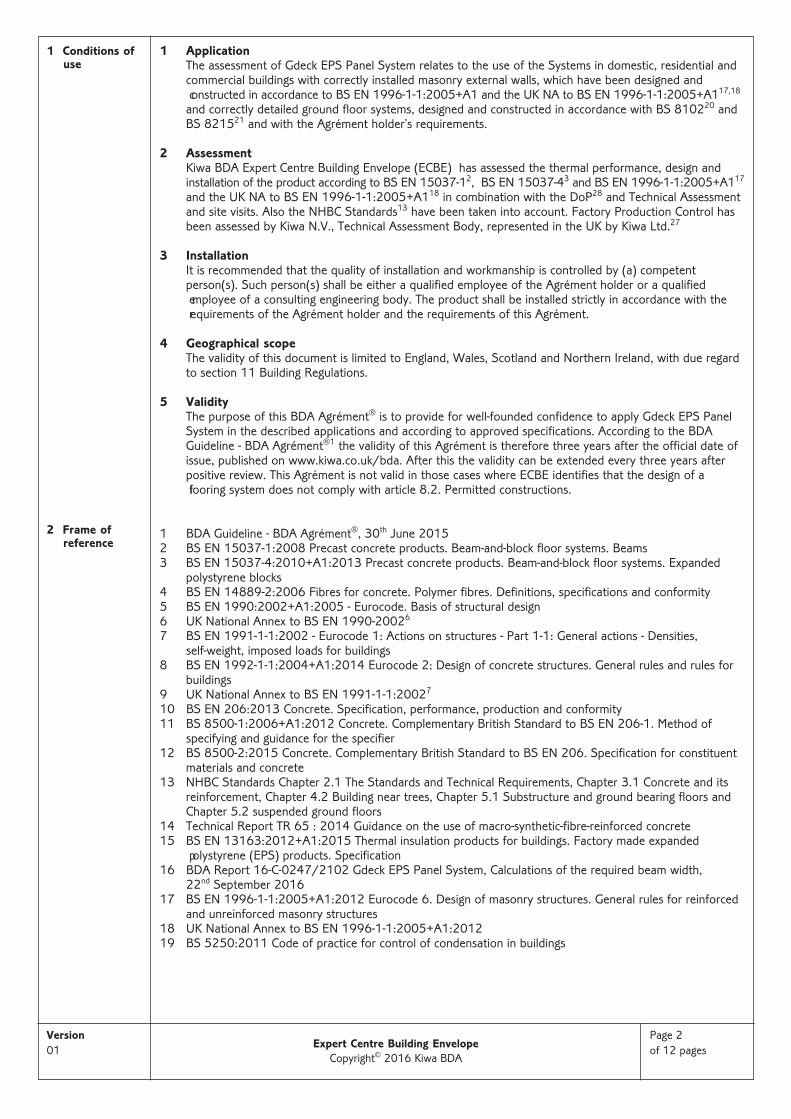
Figure 1 - Required total beam width parallel under partition wall, for EPS 250
- The minimal required beam width (m) under a partition wall is given in BDA Report 16-C-0247/210216.
• Beams perpendicular under partition walls (per m•m-1)- The required beam width for the EPS rails of EPS 250 is given in Figure 216.
Figure 2 - Required total beam width per m•m-1 perpendicular under partition walls, for EPS 250
- The minimal required beam width per m•m-1 under a partition wall is given in BDA Report 16-C-024716.
Guidance for the specifiers of T-beam supported suspended floors- partition walls running parallel to beams shall be installed directly above, or within a maximum distance
from supporting beams; - partition walls perpendicular to beams shall be supported by a minimum number of beams according to
the Agrément holders requirements;- the exact position of partition walls will vary according to beam width and configuration; - the Agrément holders guidelines are supplementary to the structural requirements of the beams
themselves and shall be taken into consideration by the specifier of the floor.
Version01
Page 4of 12 pagesExpert Centre Building Envelope
Copyright© 2016 Kiwa BDA
3 Independentlyassessed systemcharacteristicsof componentsused for criticalfunctions**)
(continued)
4 Independentlyassessed ancillaryitems usedused for criticalfunctions**)
**) see section 3
5 Factory Production Control (FPC)
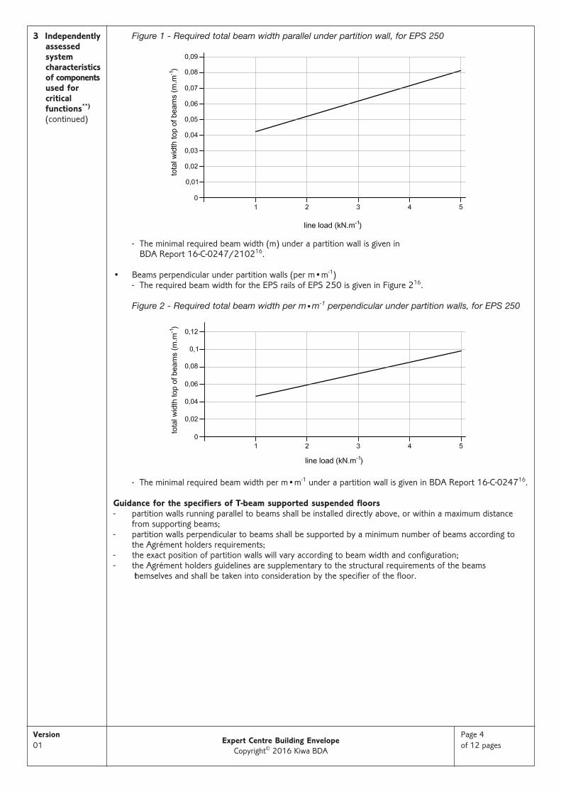
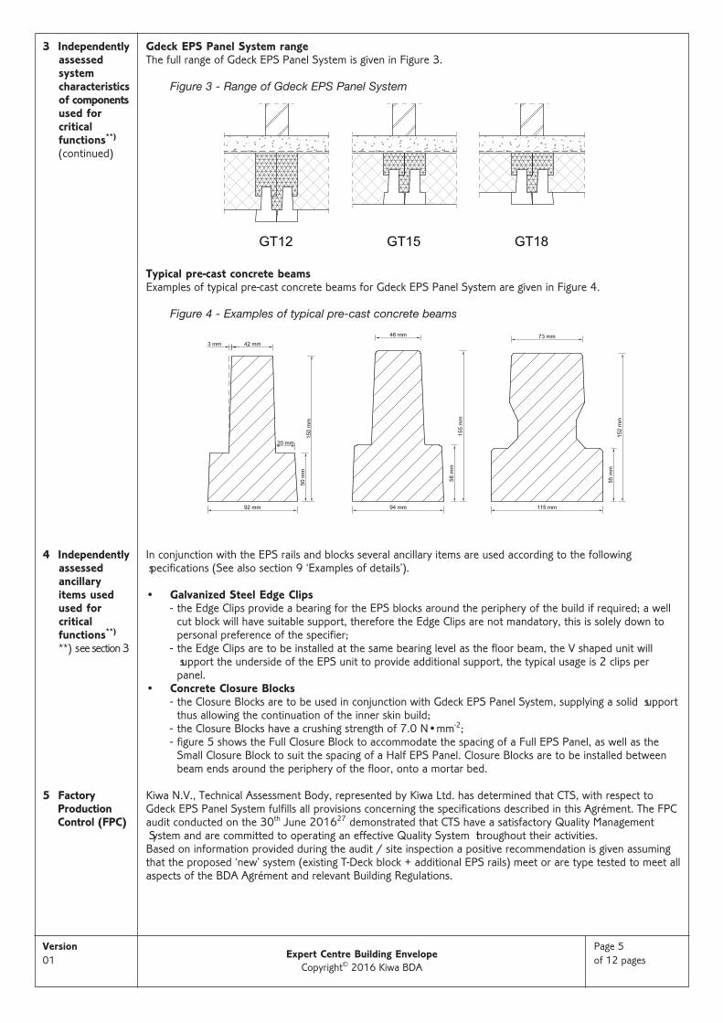
Gdeck EPS Panel System range The full range of Gdeck EPS Panel System is given in Figure 3.
Figure 3 - Range of Gdeck EPS Panel System
Typical pre-cast concrete beamsExamples of typical pre-cast concrete beams for Gdeck EPS Panel System are given in Figure 4.
Figure 4 - Examples of typical pre-cast concrete beams
In conjunction with the EPS rails and blocks several ancillary items are used according to the following specifications (See also section 9 ‘Examples of details’).
• Galvanized Steel Edge Clips - the Edge Clips provide a bearing for the EPS blocks around the periphery of the build if required; a well
cut block will have suitable support, therefore the Edge Clips are not mandatory, this is solely down topersonal preference of the specifier;
- the Edge Clips are to be installed at the same bearing level as the floor beam, the V shaped unit will support the underside of the EPS unit to provide additional support, the typical usage is 2 clips perpanel.
• Concrete Closure Blocks- the Closure Blocks are to be used in conjunction with Gdeck EPS Panel System, supplying a solid support
thus allowing the continuation of the inner skin build; - the Closure Blocks have a crushing strength of 7.0 N•mm-2; - figure 5 shows the Full Closure Block to accommodate the spacing of a Full EPS Panel, as well as the
Small Closure Block to suit the spacing of a Half EPS Panel. Closure Blocks are to be installed betweenbeam ends around the periphery of the floor, onto a mortar bed.
Kiwa N.V., Technical Assessment Body, represented by Kiwa Ltd. has determined that CTS, with respect toGdeck EPS Panel System fulfills all provisions concerning the specifications described in this Agrément. The FPCaudit conducted on the 30th June 201627 demonstrated that CTS have a satisfactory Quality Management System and are committed to operating an effective Quality System throughout their activities. Based on information provided during the audit / site inspection a positive recommendation is given assumingthat the proposed ‘new’ system (existing T-Deck block + additional EPS rails) meet or are type tested to meet allaspects of the BDA Agrément and relevant Building Regulations.
Version01
Page 5of 12 pagesExpert Centre Building Envelope
Copyright© 2016 Kiwa BDA
6 Quality ManagementSystem
7 Continuoussurveillance
8 Points of attention for the specifier
CTS operate an effective and well maintained Quality Management System (QMS). CTS has an effective QMS / QP System in operation (based on their 9001 certification). The Quality System covers most clauses required by the BDA Agrément®. CTS are committed to improving their FPC Quality System and related procedures. Document control and production line procedures were satisfactory with sufficient evidence provided in support of BDA requirements.
All processes in the factory were well organised and the factory has sufficient (but limited) space for conductingall processes including storage of raw materials and packaging of final products. All area managers and employees are well trained and confident in executing their respective tasks.
In order to demonstrate that the FPC is in conformity with the requirements of the technical specification described in this Agrément the continuous surveillance, assessment and approval of the FPC will be done in afrequency of not less than once per year by Kiwa Ltd.
1 Delivery, transport and site handling- the EPS blocks and rails are shrink-wrapped and bonded in cube packs, but otherwise unprotected;
therefore, care shall be taken during transit and storage to avoid damage; particular attention is requiredfor blocks with extended toe widths; further measures are given in section 10.
2 Permitted constructions- only constructions designed according to the specifications as given in this Agrément and as shown in
section 9 or similar are allowed under this Agrément; in each case the specifier will have to cooperateclosely with the Agrément holder.
3 Control of Floor Design- CTS only grant licences to distribute Gdeck to beam suppliers who have obtained confirmation, from a
suitably competent third party engineer, that beams they manufacture comply with the criteria specifiedin BS EN 15037-12, BS EN 1991-1-17 and BS EN 1992-1-18;
- CTS approved distributors receive site plans from customers requiring detailed floor designs to meetstructural and thermal performance; the distributor’s technical departments design floor layouts, usingbeams made to BS EN 1991-1-17 and BS EN 1992-1-18 obeying maximum loading spans to create themost effective layouts for customer structural installation;
- CTS have appointed Moulded Foams (manufacturer of the EPS components of Gdeck EPS Panel System)as the sole provider of Gdeck EPS parts within the UK; Moulded Foams provide Approved Gdeck distributors with Gdeck U-value performance tables specific to their beam profile;
- once designers have created a suitable floor design, they calculate the perimeter/area ratio and use supplied Gdeck U-value Performance Tables to determine which Gdeck thickness detail is required to beinstalled.
4 Building physics - general- the building physical behaviour of floors incorporating a Gdeck EPS Panel System shall be verified as
suitable by a specialist; the specialist can be either a qualified employee of the specifier or a qualified consultant;
- the qualified person will check the building physical behaviour of the designed floor construction and ifneed be, advise about improvement to achieve the final specification; it is recommended that he wouldcooperate closely with the Agrément holder.
5 Thermal performance aspects- for the purpose of U-value calculations and to determine if the requirements of the Building (or other
statutory) Regulations are met, the thermal resistances of the constructions shall be calculated accordingto BS EN ISO 694622, BR44323, and BS EN ISO 1021124 as appropriate; also the recommendations inthe Thermal Bridging Guide26 should be observed;
- the Agrément holder can provide a service to provide for 2D and 3D calculations for numerically modelled EPS block and beam configurations, complying to BS EN ISO 1337025, BS EN ISO 1021124
and BR 49733;- the requirement for limiting the heat loss through the building fabric, including the effect of thermal
bridging can be satisfied if the U-values of the building elements do not exceed the maximum values inthe relevant Elemental Methods given in the National Building Regulations of England (Approved Document L), Wales (Approved Document L), Scotland (Technical Standards Regulations 9) and Northern Ireland (Technical Booklet F); further information on regulations is given in section 11 of thisAgrément.
Version01
Page 6of 12 pagesExpert Centre Building Envelope
Copyright© 2016 Kiwa BDA

8 Points of attention for the specifier
(continued)
6 Junction linear thermal transmittance (ψ) values- the Agrément holder’s service for numerical calculations also includes calculations for ψ-values such as
given in section 9 including external walls (perpendicular and parallel), party walls, thresholds and temperature factors;
- these ψ-values depend on several parameters such as system types (Figure 3) beam dimensions (Figure 4),EPS block and beam configurations, external wall configurations and foundation configurations;
- default system ψ-values are given in Table 1, other values can be modelled according to BR 49733 andthe provisions in the documents supporting the National Building Regulations relating to competency toperform calculations, determine robustness of design/construction and limiting heat loss by air infiltration.
Table 1 - Default ψ-values (W•m-1•K-1), according to SAP 2012 Conventions32
7 Condensation risk- external walls and ground floors incorporating the systems will adequately limit the risk of interstitial
condensation when designed in accordance with BS 525019; a condensation risk analysis shall be completed at design stage;
- to help minimise the risk of interstitial condensation, the void space beneath the lowest point of the floorconstruction shall be at least 150 mm high, with provision for adequate through-ventilation in the form ofventilation openings provided in two opposing external walls; the ventilation openings shall be not lessthan 1500 mm2•m-1 run of external wall or 500 mm2•m-2 of floor area, whichever is the greater; wherepipes are used to carry ventilating air, these shall be at least 100 mm in diameter;
- when designed and installed in accordance with this Agrément the systems will contribute to a convection-free envelope of high vapour resistance;
- to minimise the risk of interstitial condensation at junctions with external walls, specifiers shall ensure thatwall insulation extends to at least 150 mm below the top of the EPS blocks;
- to minimise the risk of condensation at service penetrations, care should be taken to minimise gaps in theinsulation layer, for example by filling with expanding foam insulation.
8 Structural performance8.1 General
- structural screeds shall be designed by suitably qualified persons in accordance with BS EN 20610 and itscomplementary British Standard BS 8500-212. Reinforcement consisting of welded steel mesh should bein accordance with BS EN 15037-12;
- the structural engineer must ensure that the concrete beams and structural topping are suitable for theintended use.
8.2 EPS infill blocks and load bearing rails- the EPS infill blocks and load bearing rails provide a formwork to the structural concrete topping; only
the load bearing rails make a further contribution to the long-term structural performance of the floor inthe form of load spreading (see section 3), once the structural concrete topping has been placed and hasobtained its full design strength;
- EPS blocks cut to less than 300 mm long, to accommodate varying beam lengths, shall be positioned atthe floor edges; starter and end blocks should not be more than 300 mm wide at the top;
- the EPS blocks are designed to have a normal bearing of 20 mm, with a 5 mm allowance for misalignment and manufacturing tolerances in the straightness of the beam; a minimum bearing width of15 mm must therefore be ensured;
- the EPS load bearing rails have adequate resistance to short-term and long-term creep compression (see section 3);
- to reduce the risk of accidental penetration of the EPS during the construction phase spacers (4 per m2
and dimensions not less than 50 mm x 50 mm) for supporting mesh reinforcement should be located onspreader plates over the EPS infill blocks and load bearing rails.
8.3 Structural concrete topping- the concrete topping thickness and reinforcement specification shall be determined in accordance with
BS EN 1992-1-18 by a qualified structural engineer;- the concrete topping shall be according to BS 8500-111, BS 8500-212 and BS EN 20610, manufactured
in plants covered by the QSRMC scheme (Quality Scheme for Ready Mixed Concrete) and laid by personnel with the appropriate skills and experience;
- the specifications in Table 2 are suitable for single-family self-contained dwelling units and communal areas in blocks of flats with the characteristic imposed loads defined in Table 4;
- the concrete specifications in Table 3 are suitable for commercial buildings with the characteristic imposed loads defined in Table 5.
Version01
Page 7of 12 pagesExpert Centre Building Envelope
Copyright© 2016 Kiwa BDA
Junction ψ-valueExternal wall 0,32
Party wall 0,16
8 Points of attention for the specifier
(continued)
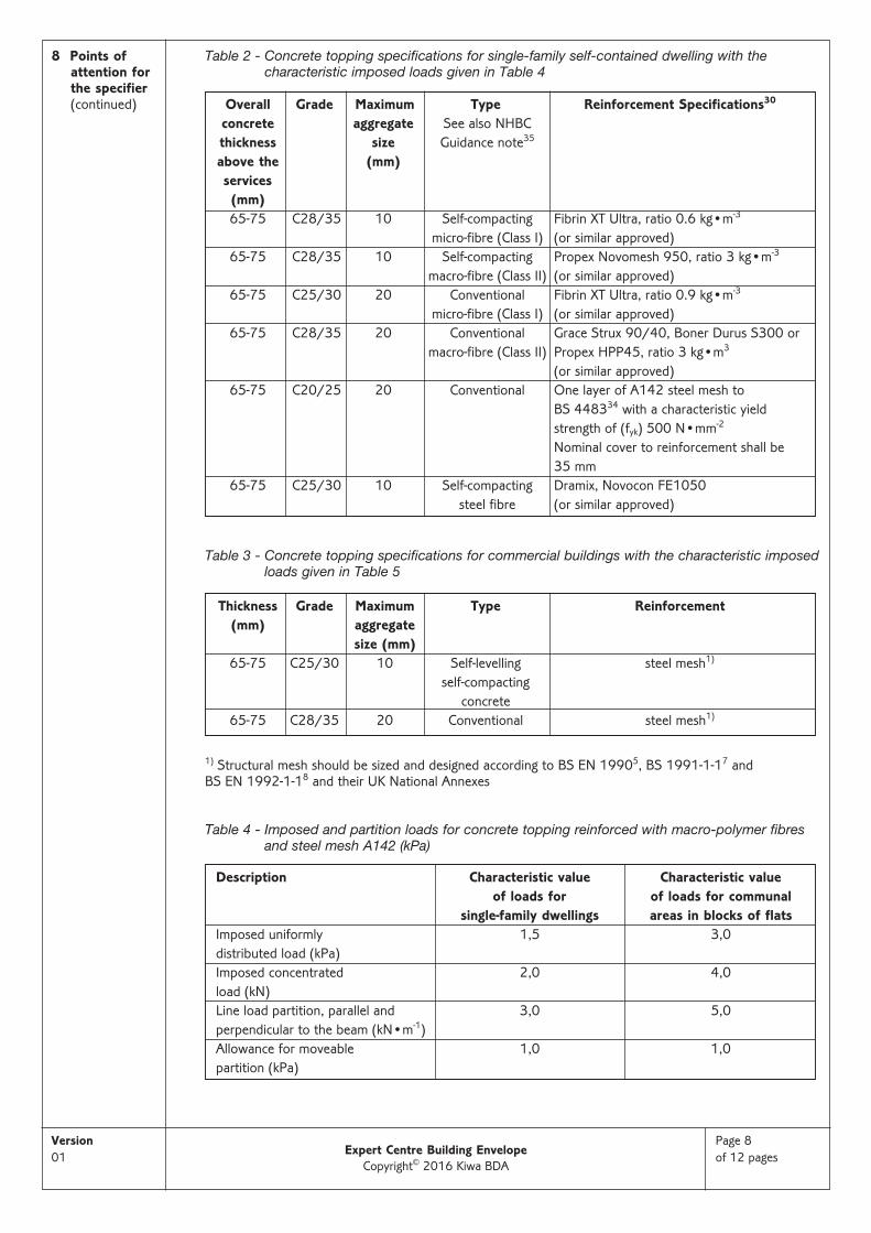
Table 2 - Concrete topping specifications for single-family self-contained dwelling with the characteristic imposed loads given in Table 4
Table 3 - Concrete topping specifications for commercial buildings with the characteristic imposedloads given in Table 5
1) Structural mesh should be sized and designed according to BS EN 19905, BS 1991-1-17 and BS EN 1992-1-18 and their UK National Annexes
Table 4 - Imposed and partition loads for concrete topping reinforced with macro-polymer fibresand steel mesh A142 (kPa)
Version01
Page 8of 12 pagesExpert Centre Building Envelope
Copyright© 2016 Kiwa BDA
Overall Grade Maximum Type Reinforcement Specifications30
concrete aggregate See also NHBCthickness size Guidance note35
above the (mm)services
(mm)65-75 C28/35 10 Self-compacting Fibrin XT Ultra, ratio 0.6 kg•m-3
micro-fibre (Class I) (or similar approved)65-75 C28/35 10 Self-compacting Propex Novomesh 950, ratio 3 kg•m-3
macro-fibre (Class II) (or similar approved)65-75 C25/30 20 Conventional Fibrin XT Ultra, ratio 0.9 kg•m-3
micro-fibre (Class I) (or similar approved)65-75 C28/35 20 Conventional Grace Strux 90/40, Boner Durus S300 or
macro-fibre (Class II) Propex HPP45, ratio 3 kg•m3
(or similar approved)65-75 C20/25 20 Conventional One layer of A142 steel mesh to
BS 448334 with a characteristic yieldstrength of (fyk) 500 N•mm-2
Nominal cover to reinforcement shall be 35 mm
65-75 C25/30 10 Self-compacting Dramix, Novocon FE1050 steel fibre (or similar approved)
Thickness Grade Maximum Type Reinforcement(mm) aggregate
size (mm)65-75 C25/30 10 Self-levelling steel mesh1)
self-compacting concrete
65-75 C28/35 20 Conventional steel mesh1)
Description Characteristic value Characteristic value of loads for of loads for communal
single-family dwellings areas in blocks of flatsImposed uniformly 1,5 3,0distributed load (kPa)Imposed concentrated 2,0 4,0load (kN)Line load partition, parallel and 3,0 5,0perpendicular to the beam (kN•m-1)Allowance for moveable 1,0 1,0 partition (kPa)

8 Points of attention for the specifier
(continued)
9 Examples ofdetails
Table 5 - Imposed and partition loads for commercial buildings and concrete topping reinforcedwith steel mesh
8.4 Pre-stressed concrete beams- examples of typical pre-stressed beams are given in section 3, Figure 4;- the self-bearing pre-stressed concrete beams provide for the final strength of the floor system
independently of any other constituent part of the floor system;- the pre-stressed concrete beams must be designed in accordance with BS EN 1992-1-1 (Eurocode 2)8
and its UK National Annex by a qualified and experienced individual to ensure that the beams are adequate to resist the applied loading;
- the proposed pre-stressed concrete beam must be CE marked, and manufactured and designed accordingto BS EN 15037-12;
- the serviceability deflection limit of the proposed concrete beam must be in accordance withBS EN 1992-1-18;
- the maximum effective span of the concrete beam (assumed to be a simply-supported and self-bearingbeam) must be calculated using the equations from BS EN 19905;
- where - e.g. under non-load-bearing walls - two or more concrete beams are placed side by side, thespaces between the beam webs should be in-filled with concrete with a minimum strength class ofC25/30 to provide unity of action.
9 Maintenance and consulting service- once installed strictly in accordance with the requirements of this Agrément and of the Agrément holder,
the system components are within the floor structure, therefore do not require maintenance;- for specific calculation for robust details of wall and floor the Agrément holder can provide a technical
consulting service for calculations and installation advice.
10 Durability- once installed the EPS components are protected in service from agents liable to cause deterioration and
will be effective as insulation for the life of the building in which they are installed;- beneath a suspended ground floor over a ventilated void and soil the exposure condition is class XC1,
in accordance with BS EN 1992-1-18; the concrete beams will have adequate durability for this exposurecondition;
- the concrete topping reinforced with steel mesh or macro-polymer fibres will have adequate durability forexposure class XC1.
Figure 5 - Gdeck EPS Panel System - GT detail 12 Floor/Wall Junction - depth 250 mm
Version01
Page 9of 12 pagesExpert Centre Building Envelope
Copyright© 2016 Kiwa BDA
Description Characteristicvalues of loads
Imposed UDL (kPa) 5,0Imposed concentrated load (kN) 4,5Line load partition parallel and 5,0perpendicular to the beam (kN•m-1)Allowance for moveable 1,0partition (kPa)
9 Examples ofdetails
(continued)
10 Installationprocedure
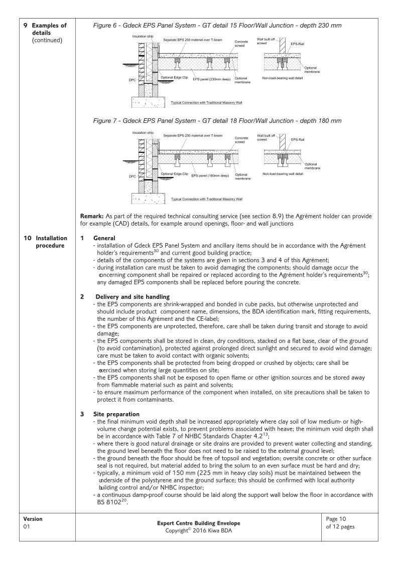
Figure 6 - Gdeck EPS Panel System - GT detail 15 Floor/Wall Junction - depth 230 mm
Figure 7 - Gdeck EPS Panel System - GT detail 18 Floor/Wall Junction - depth 180 mm
Remark: As part of the required technical consulting service (see section 8.9) the Agrément holder can provide for example (CAD) details, for example around openings, floor- and wall junctions
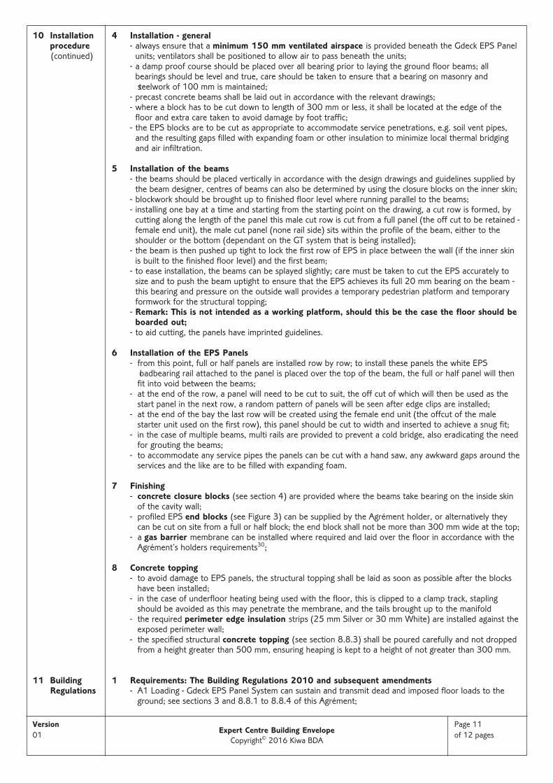
1 General- installation of Gdeck EPS Panel System and ancillary items should be in accordance with the Agrément
holder’s requirements30 and current good building practice;- details of the components of the systems are given in sections 3 and 4 of this Agrément;- during installation care must be taken to avoid damaging the components; should damage occur the
concerning component shall be repaired or replaced according to the Agrément holder’s requirements30;any damaged EPS components shall be replaced before pouring the concrete.
2 Delivery and site handling- the EPS components are shrink-wrapped and bonded in cube packs, but otherwise unprotected and
should include product component name, dimensions, the BDA identification mark, fitting requirements,the number of this Agrément and the CE-label;
- the EPS components are unprotected, therefore, care shall be taken during transit and storage to avoiddamage;
- the EPS components shall be stored in clean, dry conditions, stacked on a flat base, clear of the ground(to avoid contamination), protected against prolonged direct sunlight and secured to avoid wind damage;care must be taken to avoid contact with organic solvents;
- the EPS components shall be protected from being dropped or crushed by objects; care shall be exercised when storing large quantities on site;
- the EPS components shall not be exposed to open flame or other ignition sources and be stored awayfrom flammable material such as paint and solvents;
- to ensure maximum performance of the component when installed, on site precautions shall be taken toprotect it from contaminants.
3 Site preparation- the final minimum void depth shall be increased appropriately where clay soil of low medium- or high-
volume change potential exists, to prevent problems associated with heave; the minimum void depth shallbe in accordance with Table 7 of NHBC Standards Chapter 4.213;
- where there is good natural drainage or site drains are provided to prevent water collecting and standing,the ground level beneath the floor does not need to be raised to the external ground level;
- the ground beneath the floor should be free of topsoil and vegetation; oversite concrete or other surfaceseal is not required, but material added to bring the solum to an even surface must be hard and dry;
- typically, a minimum void of 150 mm (225 mm in heavy clay soils) must be maintained between the underside of the polystyrene and the ground surface; this should be confirmed with local authority building control and/or NHBC inspector;
- a continuous damp-proof course should be laid along the support wall below the floor in accordance withBS 810220.
Version01
Page 10of 12 pagesExpert Centre Building Envelope
Copyright© 2016 Kiwa BDA
10 Installationprocedure
(continued)
11 BuildingRegulations
4 Installation - general- always ensure that a minimum 150 mm ventilated airspace is provided beneath the Gdeck EPS Panel
units; ventilators shall be positioned to allow air to pass beneath the units;- a damp proof course should be placed over all bearing prior to laying the ground floor beams; all
bearings should be level and true, care should be taken to ensure that a bearing on masonry and steelwork of 100 mm is maintained;
- precast concrete beams shall be laid out in accordance with the relevant drawings;- where a block has to be cut down to length of 300 mm or less, it shall be located at the edge of the
floor and extra care taken to avoid damage by foot traffic;- the EPS blocks are to be cut as appropriate to accommodate service penetrations, e.g. soil vent pipes,
and the resulting gaps filled with expanding foam or other insulation to minimize local thermal bridgingand air infiltration.
5 Installation of the beams- the beams should be placed vertically in accordance with the design drawings and guidelines supplied by
the beam designer, centres of beams can also be determined by using the closure blocks on the inner skin;- blockwork should be brought up to finished floor level where running parallel to the beams;- installing one bay at a time and starting from the starting point on the drawing, a cut row is formed, by
cutting along the length of the panel this male cut row is cut from a full panel (the off cut to be retained -female end unit), the male cut panel (none rail side) sits within the profile of the beam, either to theshoulder or the bottom (dependant on the GT system that is being installed);
- the beam is then pushed up tight to lock the first row of EPS in place between the wall (if the inner skinis built to the finished floor level) and the first beam;
- to ease installation, the beams can be splayed slightly; care must be taken to cut the EPS accurately tosize and to push the beam uptight to ensure that the EPS achieves its full 20 mm bearing on the beam -this bearing and pressure on the outside wall provides a temporary pedestrian platform and temporaryformwork for the structural topping;
- Remark: This is not intended as a working platform, should this be the case the floor should beboarded out;
- to aid cutting, the panels have imprinted guidelines.
6 Installation of the EPS Panels- from this point, full or half panels are installed row by row; to install these panels the white EPS
loadbearing rail attached to the panel is placed over the top of the beam, the full or half panel will thenfit into void between the beams;
- at the end of the row, a panel will need to be cut to suit, the off cut of which will then be used as thestart panel in the next row, a random pattern of panels will be seen after edge clips are installed;
- at the end of the bay the last row will be created using the female end unit (the offcut of the malestarter unit used on the first row), this panel should be cut to width and inserted to achieve a snug fit;
- in the case of multiple beams, multi rails are provided to prevent a cold bridge, also eradicating the needfor grouting the beams;
- to accommodate any service pipes the panels can be cut with a hand saw, any awkward gaps around theservices and the like are to be filled with expanding foam.
7 Finishing - concrete closure blocks (see section 4) are provided where the beams take bearing on the inside skin
of the cavity wall;- profiled EPS end blocks (see Figure 3) can be supplied by the Agrément holder, or alternatively they
can be cut on site from a full or half block; the end block shall not be more than 300 mm wide at the top;- a gas barrier membrane can be installed where required and laid over the floor in accordance with the
Agrément’s holders requirements30;
8 Concrete topping- to avoid damage to EPS panels, the structural topping shall be laid as soon as possible after the blocks
have been installed; - in the case of underfloor heating being used with the floor, this is clipped to a clamp track, stapling
should be avoided as this may penetrate the membrane, and the tails brought up to the manifold- the required perimeter edge insulation strips (25 mm Silver or 30 mm White) are installed against the
exposed perimeter wall;- the specified structural concrete topping (see section 8.8.3) shall be poured carefully and not dropped
from a height greater than 500 mm, ensuring heaping is kept to a height of not greater than 300 mm.
1 Requirements: The Building Regulations 2010 and subsequent amendments- A1 Loading - Gdeck EPS Panel System can sustain and transmit dead and imposed floor loads to the
ground; see sections 3 and 8.8.1 to 8.8.4 of this Agrément;
Version01
Page 11of 12 pagesExpert Centre Building Envelope
Copyright© 2016 Kiwa BDA
11 BuildingRegulations
(continued)
- C2(c) Resistance to moisture - the blocks and load bearing rails will contribute to limiting the risk of surface and interstitial condensation; see section 8.6 of this Agrément;
- L1(a)(i) Conservation of fuel and power - the blocks and load bearing rails will contribute to satisfyingthis Requirement; see sections 8.3 to 8.5 of this Agrément;
- Regulation 7 Materials and workmanship - Gdeck EPS Panel System is manufactured from suitably safeand durable materials for its application and can be installed to give a satisfactory performance, see section 10 of this Agrément.
Regulation 26 - (0) - CO2 emission rates for new buildings and - (A) - Fabric energy efficiency rates for new dwellings - the blocks and load bearing rails will contribute to satisfying these Regulations; see sections 8.4 and 8.5 of this Agrément.
2 Requirements: The Building (Amendment) Regulations 2014 (Wales) and subsequent amendments- A1 Loading - Gdeck EPS Panel System can sustain and transmit dead and imposed floor loads to the
ground; see sections 3 and 8.8.1 to 8.8.4 of this Agrément;- C2(c) Resistance to moisture - the blocks and load bearing rails will contribute to limiting the risk of
surface and interstitial condensation; see section 8.6 of this Agrément;- L1(a)(i) Conservation of fuel and power - the blocks and load bearing rails will contribute to satisfying
this Requirement; see sections 8.3 to 8.5 of this Agrément; - Regulation 7 Materials and workmanship - Gdeck EPS Panel System is manufactured from suitably safe
and durable materials for its application and can be installed to give a satisfactory performance, see section 10 of this Agrément.
Regulation 26 - (0) - CO2 emission rates for new buildings and- (A) - Primary energy consumption rates for new buildings - (B) - Fabric performance values for new dwellings - the blocks and load bearing rails will contribute to satisfying these Regulations; see sections 8.4 and 8.5 of this Agrément.
3 Requirements: The Building (Scotland) Regulations 2004 and subsequent amendments3.1 Regulations 8 (1)(2) Durability of materials and workmanship
- Gdeck EPS Panel System is manufactured from acceptable materials and is considered to be adequatelyresistant to deterioration and wear under normal service conditions, provided it is installed in accordancewith the requirements of this Agrément, see section 10 of this Agrément.
3.2 Regulation 9 Building Standards-Construction - 1.1 (a)(b) Structure - Gdeck EPS Panel System can sustain and transmit dead and imposed floor loads to
the ground; see sections 3 and 8.8.1 to 8.8.4 of this Agrément;- 3.15 - Condensation - the blocks and load bearing rails will contribute to limiting the risk of surface and
interstitial condensation; see section 8.6 of this Agrément;- 6.1(b) - Carbon dioxide emissions
6.2 - Building insulation envelope- the blocks and load bearing rails will contribute to satisfying the requirements of theseStandards; see sections 8.4 and 8.5 of this Agrément;
- 7.1(a)(b) - Statement of sustainability - the blocks can contribute to satisfying the relevant Requirementsof Regulation 9, Standards 1 to 6, and therefore will contribute to a construction meeting a bronze levelof sustainability as defined in this Standard; in addition, the blocks can contribute to a constructionmeeting a higher level of sustainability as defined in this Standard; see sections 8.4 and 8.5 of this Agrément.
3.3 Regulation 12 Building Standards-ConversionsAll comments given for Gdeck EPS Panel System under Regulation 9 also apply to this Regulation, with reference to clause 0.12 and Schedule 6 of this Standard.
4 Requirements: The Building Regulations 2012 (Northern Ireland) and subsequentamendments- 23(a)(i)(iii)(b) Fitness of materials and workmanship - Gdeck EPS Panel System is manufactured from
materials which are considered to be suitably safe and acceptable for use as thermal insulation as described in sections 8 and 10 of this Agrément;
- 28 Resistance to moisture and weather - Gdeck EPS Panel System can be constructed so as to preventany harmful effect on the building or the health of the occupants caused by the passage of moisture toany part of the building from (a) the ground and (b) the weather;
- 29 Condensation - the blocks and load bearing rails will contribute to limiting the risk of surface and interstitial condensation; see section 8.6 of this Agrément.
- 30 Stability - Gdeck EPS Panel System can sustain and transmit dead and imposed floor loads to theground; see sections 3 and 8.8.1 to 8.8.4 of this Agrément;
- 39(a)(i) - Conservation measures 40(2) - Target carbon dioxide emission rate
- the blocks and load bearing rails will contribute to satisfying the requirements of these Standards; see sections 8.4 and 8.5 of this Agrément.
Version01
Page 12of 12 pagesExpert Centre Building Envelope
Copyright© 2016 Kiwa BDA