284796797 German ATV DVWK a 168E Corrosion of Wastewater Systems Wastewater 1998 PDF
COATINGS MANUAL HRSD
OD/ Coatings Manual 2011 Appendix A -1- 9/7/05
APPENDIX A
BASICS ON CORROSION IN WASTEWATER COLLECTION AND TREATMENT SYSTEMS:
The Corroding Environments and Materials
A. Corrosiveness Of Wastewater “Wastewater” in a municipal setting consists of relatively weak solutions of non aggressive contaminant chemicals in “used” water. The water is collected and conveyed to the treatment plant in pipes made of common materials, including cement mortar lined cast (ductile) iron, precast concrete, vitrifed clay and plastic, which includes a variety of thermoplastic or thermoset materials. The types and concentrations of contaminants in raw wastewater from domestic sources are well known - fats, oils, greases, soaps, organic matter, dirt, human waste, food waste, etc. - normally at total concentrations below 1000 ppm (0.1 per cent). From a corrosion perspective, the sewage is no more corrosive than ordinary “fresh” water, i.e., water that is neither acidic nor alkaline. Wastewater is aerated in most parts of the wastewater system, at least where the biological reactions do not consume all the dissolved oxygen. In areas where waste water is not aerated, it produces much more corrosive conditions for many materials. The most common chemical contaminants in domestic wastewater are chlorides, nitrogen compounds and a wide variety of organic compounds. Sulfate and phosphate ions are present. The pH of domestic wastewater typically is between 6 and 7, running slightly on the alkaline side of neutral where there is higher use of soaps and household cleansing materials, most of which are mildly alkaline to increase their detergent effectiveness. Used water from manufacturing plants and factories - also called “trade waste”- can have a wider range of contaminants - some of which may significantly affect the corrosiveness of the wastewater. However, most trade waste streams today must meet limits for contamination levels, especially for pH and heavy metal ions, set by the treatment plant that accepts them. Today, industrial contributors of wastewater are required to provide pH control and chemical pretreatment of their waste water for the removal of heavy metal ions. However if not properly managed, metals removal and pH control can affect the corrosivity and toxicity of the wastewater in municipal collection and treatment systems.
B. Microbiological Considerations Sewage and other wastewaters contain significant levels of biological and organic materials, including many bacteria that remain active in the waste streams. From a corrosion point of view, the most important types of bacteria are those that metabolize sulfur compounds because this microbiological activity can produce acidic chemicals that are corrosive to concrete and steel or iron. Some bacteria also oxidize ferrous ions to ferric ions, which makes the local environment more corrosive to carbon steel. The most prolific and important
COATINGS MANUAL HRSD
OD/ Coatings Manual 2011 Appendix A -2- 9/7/05
bacteria in wastewater streams and systems are the genus thiobacillus. These organisms grow best at 25-35°C. They are able to oxidize sulfide, elemental S, thiosulfate, and polythionite. The genus Thiobacillus can be broken into two groups. The first are those that grow only at neutral pH values. These are responsible for the conversion of elemental sulfur into sulfuric acid. Another group grows at lower pH values and can utilize Fe2+ as an electron donor. In this second group, Thiobacillus thiooxidans has a much more acidic growth range. It grows best between 2 to 5 and is also strictly aerobic. Thiobacillus intermedius is most active in a pH range of 3 to 7, gets its electrons from (i.e., oxidizes) thiosulfate ions (S2O3
2-), and is stimulated by the presence of organic matter. Thiobacillus ferrooxidans is strictly aerobic and it has a pH growth range of 1.5 to 5. It can oxidize Fe2+ to Fe3
+. The most common way these microorganisms effect wastewater streams is by growing colonies in the organic slimes and deposits that form, usually in headspaces above the flowing wastewater. The local environment created by the “bugs” can become acidic enough to dissolve concrete and to corrode steel and ductile iron. Another important commercial problem due to the action of Thiobacillus ferrooxidans in particular, is the formation of highly insoluble, ferric oxyhydroxide mounds that can clog steel or iron pipes. The production of sulfuric acid is the major problem related to Thiobacillus. Formation of H2SO4 in municipal wastewater systems is a two-stage process: bacteria produce sulfide ions and hydrogen sulfide, which are metabolized by other bacteria to produce oxidized sulfur species that react with water to produce sulfuric acid. Bio-Generation Of Sulfides Domestic septic sewage contains an ample supply of sulfate ions (SO4
2-). Within the slime layers that form on sewer piping and other sewage handling surfaces, sulfate reducing bacteria (SRB) also exist. SRB are anaerobic and are dormant until the slime layer is thick enough to cut off the dissolved oxygen and produce anaerobic conditions. Once this occurs, usually within 1 or 2 weeks, depending upon local conditions, the SRB metabolize the sulfate ions – reducing them to sulfide ions (S2-). The sulfide ions react with hydrogen ions in the wastewater to form hydrosulfide, also called the bisulfide ion (HS-). HS- ions react with water to produce hydrogen sulfide (H2S) in the dissolved form. Bisulfide ions acidify the water, increasing the concentration of hydrogen ions. This speeds up formation of HS- ions and of H2S gas. Dissolved H2S gas comes out of solution at regions of turbulence, but more gas forms to replace it. H2S coming out of solution and entering the atmosphere causes the familiar “rotten egg” odor. Gaseous H2S acidifies surface moisture in headspaces of enclosed or covered structures, causing acidic corrosion of concrete or metal surfaces. H2S and oxygen combine to form polythionic acids – a weak form of sulfuric acid. Bio-Generation Of Sulfuric Acid Sulfur-oxidizing bacteria (SOB) colonize on wet surfaces with pH above about 9.5 and if oxygen is present. Aerobic SOB are especially active in a nutrient rich, scum layer generally
COATINGS MANUAL HRSD
OD/ Coatings Manual 2011 Appendix A -3- 9/7/05
found just above the waterline. SOB uses dissolved oxygen to metabolize H2S and other sulfides to sulfuric acid (H2SO4).
As noted earlier, the acid-generating SOB are mainly members of the Thiobacillus genus. Many species of Thiobacillus are involved in the production of sulfuric acid in sewer systems. Different types of thiobacillus bacteria thrive under different conditions, including pH. If one type can no longer survive because conditions become too acidic, another will take over. This process continues to very acidic pH levels around 1.0, provided the bacteria also have enough nutrient, H2S and dissolved oxygen to keep conditions aerobic. Modern Conditions Are More Severe Hydrogen sulfide (H2S) is always present in municipal wastewaters and has always caused a certain amount of acidic attack of portland cement concrete in WWT systems. (The acid-generation mechanisms are discussed above.) Through the 1970’s, H2S concentrations up to 15 ppm, but averaging 2 to 10 ppm, were commonplace in sewer pipe crowns and headspaces in conveyance/treatment structures. The acidic conditions from these levels caused only gradual concrete attack, via loss of cement paste. When H2S concentrations reach 50 ppm during periods of low sewer flow and elevated ambient temperature, such as during summer droughts, concrete attack can proceed at up to 0.5 in./yr. One proposed reason for these moderate H2S concentrations was the presence of heavy metals ions, which reduced aqueous sulfide levels in the wastewater by their toxic effect on the sulfide-generating bacteria. After the Clean Water Act of 1980 dramatically lowered the allowable levels of heavy metal ions in waste streams discharged by industrial plants, the bacteria responsible for aqueous sulfide production in wastewater systems proliferated. This resulted in more sulfide-related corrosion (and odor) problems in WWTPs in the last 25 years. Another factor leading to increased gaseous H2S concentrations in municipal wastewater treatment systems is the modern trend to transport wastewaters over longer distances to larger district or regional treatment plants. Longer retention times required to transport over longer distances usually increase the amount of wastewater that sours or goes septic. More extensive pumping of wastewater through force-mains and relatively less gravity service, which tends to be more aerobic, also have generally resulted in an increase in H2S production in the streams. This results in higher H2S gas concentrations in headspaces. Because of air quality regulations and public concerns regarding H2S related odors, many wastewater treatment tanks, clarifiers, etc. are now covered for odor control purposes, leading to stronger concentrations of H2S in the vapor spaces. In many a large WWTP today it is common to find H2S concentrations in headspaces over several hundred ppm at certain times of the year. The overall trend toward higher H2S levels has made exposure conditions significantly more severe for protective coatings or linings for concrete and metals protection in domestic WWTPs and collection systems, causing traditional coating and lining systems to fail rapidly in modern environments.
COATINGS MANUAL HRSD
OD/ Coatings Manual 2011 Appendix A -4- 9/7/05
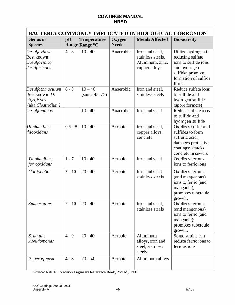
BACTERIA COMMONLY IMPLICATED IN BIOLOGICAL CORROSION Genus or Species
pH Range
Temperature Range °C
Oxygen Needs
Metals Affected Bio-activity
Desulfovibrio Best known: Desulfovibrio desulfuricans
4 - 8 10 - 40 Anaerobic Iron and steel, stainless steels, Aluminum, zinc, copper alloys
Utilize hydrogen in reducing sulfate ions to sulfide ions and hydrogen sulfide; promote formation of sulfide films.
Desulfotomaculum Best known: D. nigrificans (aka Clostridium)
6 - 8 10 – 40 (some 45–75)
Anaerobic Iron and steel, stainless steels
Reduce sulfate ions to sulfide and hydrogen sulfide (spore formers)
Desulfomonas 10 - 40 Anaerobic Iron and steel Reduce sulfate ions to sulfide and hydrogen sulfide
Thiobacillus thiooxidans
0.5 - 8 10 - 40 Aerobic Iron and steel, copper alloys, concrete
Oxidizes sulfur and sulfides to form sulfuric acid; damages protective coatings; attacks concrete in sewers
Thiobacillus ferrooxidans
1 - 7 10 - 40 Aerobic Iron and steel Oxidizes ferrous ions to ferric ions
Gallionella 7 - 10 20 - 40 Aerobic Iron and steel, stainless steels
Oxidizes ferrous (and manganous) ions to ferric (and manganic); promotes tubercule growth.
Sphaerotilus 7 - 10 20 - 40 Aerobic Iron and steel, stainless steels
Oxidizes ferrous (and manganous) ions to ferric (and manganic); promotes tubercule growth.
S. natans Pseudomonas
4 - 9 20 - 40 Aerobic Aluminum alloys, iron and steel, stainless steels
Some strains can reduce ferric ions to ferrous ions
P. aeruginosa 4 - 8 20 – 40 Aerobic Aluminum alloys
Source: NACE Corrosion Engineers Reference Book, 2nd ed., 1991
COATINGS MANUAL HRSD
OD/ Coatings Manual 2011 Appendix A
C.
Concrete Deterioration and Concrete Fundamentals
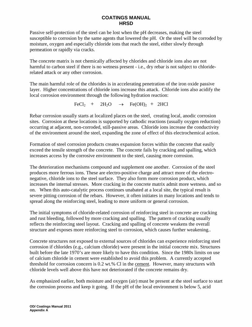
Uncoated concrete pipe and structures in wastewater service deteriorate, sometimes quickly, from exposure to a variety of chemical and physical conditions. Design and selection of appropriate protection or remedial measures for concrete in WWTPs requires an understanding of the the nature of concrete and of the chemical and physical conditions that cause concrete to deteriorate. Concrete is a composite material made from sand, rock and cement. The cement is a mixture of various minerals which, when mixed with water, hydrate and rapidly become a hard binder that locks the sand and rock into a solid mass. Portland cement is a complex mix of many compounds, some of which play a major part in the hydration or chemical characteristics of the cement. It is manufactured commercially by heating together a mixture of limestone and clay up to a temperature of 2400 - 2700°F (1300 to 1500°C). Although twenty to thirty percent of the mix becomes molten during the process the majority of the reactions which take place are solid-state in nature and therefore liable to be slow. Once cooled, the resulting clinker is ground to a fine powder and a small amount of gypsum (calcium sulphate dihydrate) is added to slow down the rate at which the cement hydrates to a workable level. The work of early investigators using optical and X-ray techniques has shown that most Portland cement clinkers contain four principal compounds. These are tricalcium silicate (3CaO.SiO2), dicalcium silicate (2CaO.SiO2), tricalcium aluminate (3CaO.Al2O3) and a ferrite phase from the (2CaO.Fe2O3 - 6CaO.2Al2O3.Fe2O3) solid solution series that at one time was considered to have the fixed composition (4CaO.Al2O3.Fe2O3). The water/cement ratio (w/c) of the mixture has the most control over the final properties of the concrete. The w/c is the relative weight of the water to the cement in the mixture and is a design criterion for the engineer. The w/c gives the engineer control over two opposing, yet desirable properties: strength and workability. Concrete mixtures with a high w/c will be more workable than mixtures with a low w/c: the “mud” will flow more easily. But, mixtures with lower w/c produce stronger cured concrete, all other things being equal. The w/c needs to be about 0.25 to complete the hydration reaction. Values of w/c between 0.40 and 0.45 typically give adequate workability and good strength. Chemical additives called “superplasticizers” can be added to a low w/c concrete mixture shortly before it is placed to significantly improve the workability (slump) of the concrete for a reasonably short time. Concrete degradation mechanisms are more easily understood if one pictures concrete as a very hard, brittle, porous or permeable material with good compressive strength, low tensile strength and minimal ductility. The lower the permeability of the cured concrete, the more durable and stronger it is. Permeability of concrete greatly depends on the w/c in the wet mix, as shown in Figure 1.

COATINGS MANUAL HRSD
OD/ Coatings Manual 2011 Appendix A
Figure 1
. Relation between permeability of concrete and water/cement ratio for mature cement paste.
The ideal lowest w/c is 0.38, but a more practical limit is to keep the w/c below 0.44. W/c values between 0.40 - 0.42 and adequate workability, or slump, in the wet mix can be conveniently achieved today by using chemical additives called “super water-reducers” or “super-placticizers”. Even good concrete has relatively low tensile strength (approximately 300 - 500 psi, or 10% of the compressive strength) and brittleness. This makes it necessary to use it in composite form, internally reinforced with steel for most structural purposes. This is most often done by embedding carbon steel bars, wire mesh or cables in the concrete. The resulting, composite material is susceptible to several types of chemical and physical attack and deterioration. This appendix reviews the types of chemical deterioration and the physical types of deterioration concrete can experience in a typical WTTP and wastewater collection system. In most cases, measures available to mitigate the deterioration and damage mechanisms also are discussed.
Chemical Deterioration
Rates of deterioration of the intrinsically alkaline concrete due to chemical attack in a WTTP depend both on the nature of the service environment and on the permeability of the concrete. The natural alkalinity of concrete makes it highly vulnerable to acid attack, but generally resistant to neutral and alkaline environments. The permeability of the concrete - related strongly to the w/c - governs how rapidly harmful agents move into or through the hardened concrete, which in turn affects how rapidly the reinforcing steel in the concrete is reached by corrosive agents including water, that corrode the steel.

COATINGS MANUAL HRSD
OD/ Coatings Manual 2011 Appendix A
The four primary mechanisms of chemical deterioration of concrete in a WWTP are:
1. Acid attack (by biogenic acids).
2. Carbonation
3. Chloride-related deterioration
4. Sulfate attack Each mechanism and common preventive measures are discussed in more detail below.
Acid Attack
Acids react with concrete in a standard, acid-base neutralization reaction. The most common acid environment in WTTP is the sulfuric acid formed by bacterial action and from reaction of hydrogen sulfide, water, and air. The rate of neutralization depends on the initial acid concentration and on the type of acid. The hardened cement paste in concrete is very alkaline, usually starting out with a pH above 12.5. When exposed to acids or acid solutions, the cement reacts with the acid to produce soluble salts. These are mostly calcium salts because the hydrated cement is about 25% calcium hydroxide. Acid attack dissolves the cement phase of the concrete away, exposing the less soluble coarse aggregate materials.
Attack of the aggregate material in the concrete depends on its chemical nature and the type of acid. Even alkaline aggregates like dolomite usually dissolve more slowly than the cement. Acid attack is therefore characterized by severe aggregate exposure and aggressive section thickness loss of the concrete. Exposed steel reinforcement is also vulnerable to acid corrosion. Prolonged exposure to mild acidic attack will be indicated by rust bleeding (from corroding reinforcing steel) and cracking and spalling of the concrete. With aggressive acid attack there is no concrete to crack and spall and only piles of loose aggregates eventually remain. Rates of attack by acids depend on the type, volume and strength (pH) of the acid, as well as on the associated physical parameters such as frequency or duration of exposure, temperature, flow rates, etc. Continuous removal of the soluble reaction compounds by washing or leaching accelerates the attack. Conversely, acid attack in stagnant conditions tends to slow as the acid is neutralized by the concrete. In sulfuric acid attack of concrete, the reaction compound is predominantly calcium sulfate or gypsum which is easily removed under flowing conditions.
Preventing Acid Attack
Resistance of regular concrete to acid attack can be improved by with dense, low permeability concrete, i.e, mixes with water:cement ratios below 0.40, and by minimizing cracking of the cured concrete mass through use of proper design, curing and placement practices. Resistance to sulfuric acids is marginally improved by using sulfate-resisting cement.
COATINGS MANUAL HRSD
OD/ Coatings Manual 2011 Appendix A
Use of micro-silica and silica fume in concrete can improve acid resistance by reducing permeability and by making the cement paste less readily soluble. However, concrete made with portland cement is generally subject to acid attack by solutions with a pH less than 5.0. Solutions with pH values below 4 will attack concrete made with any type of portland cement. Mortars based on calcium aluminum silicates (such as Lumnite) can be used for environments with pH below 5.5, but calcium aluminum silicate cement is rapidly attacked if the pH goes above 8, especially if sodium or potassium hydroxides are present. Protecting concrete against attack by strong mineral acids can be accomplished by using either very special cements, such as those based on potassium silicates, or by significantly altering the chemical nature of the cement phase of the concrete cement. Options for this include polymer concrete (PC), sulfur concrete and some polymer-modified portland cement concretes (PMC). Each of these materials offers varying degrees of resistance to acid attack, depending on the acid, its strength, the service temperature, etc. Protective barriers like coatings can prevent concrete deterioration by shielding the concrete from the acidic environment. Barrier alternatives include costly, acid-proof brick and tile linings; adhered or anchored thermoplastic sheet linings heavy duty organic, resin-based linings (most are similar to polymer concrete, but with finer aggregates), and thin-film coatings, (listed in order of decreasing cost and ruggedness.
Carbonation
Carbonation is a special type of acid attack of concrete. It involves reaction of atmospheric or dissolved carbon dioxide with the hydrated constituents in portland cement paste, especially calcium hydroxide. Carbonation in waste water treatment plants is more often a liquid phase problem than an atmospheric mechanism of attack. Carbon dioxide combines with humidity in the air to form a weak, carbonic acid. Carbonic acid that permeates the concrete reacts with the cement paste, neutralizing the alkalinity (lowering the pH) by converting hydroxides to carbonates. The products of the carbonation reaction are relatively insoluble and do not normally weaken the concrete. Carbonation occurs to some extent on all concrete surfaces exposed to the weather. Rates of carbonation depend primarily on the permeability of the concrete, the relative humidity and the temperature. More permeable concrete is carbonated more rapidly and the carbonation zone also extends deeper into the concrete. Carbonation can occur at relative humidities as low as 50 per cent. On the other hand, at relative humidities over 85 per cent, moisture tends to form in the concrete pores and slow down the rate of carbonation. Carbonation rates are accelerated if there is a large temperature gradient through the concrete, presumably because the strong condensation gradient formed pulls moisture from the warmer side to the colder side of the concrete. Liquid phase carbonation of water occurs widely in wastewater treatment plant structures primarily in aeration tanks, O2 reactors, and in other closed tanks including primary and
COATINGS MANUAL HRSD
OD/ Coatings Manual 2011 Appendix A
secondary clarifiers. It is more commonplace in O2 reactors where greater dissolved CO2 concentrations are possible due to the pressurized headspaces in these structures. The source of CO2 is derived from decomposition of organics by aerobic bacteria in the reactors or aerators. The rate of cement paste attack by liquid phase carbonation is generally very slow. Carbonation usually penetrates approximately 1/16 - 1/8 inch in the first 1 or 2 years of exposure. The pore-blocking effects of calcium carbonate and water slow this rate after the first couple of years. Eventual cement paste loss is typically 0.3 - 0.7 in. after 20 years of exposure, although this can be influenced by flow conditions. Higher rates result if flow conditions wash the surface and remove the reaction products, exposing fresh alkaline material to attack. As stated above, the main effect of carbonation is a localized reduction in the alkalinity (pH) of the concrete. By reducing the alkalinity required to keep carbon steel from corroding, carbonation that extents around the reinforcing steel makes it more susceptible to corrosion. A common symptom of carbonation is cracking that mimics the pattern of the rebar, especially the rebar closest to the surface. Carbonation also can produce a powdery surface layer when hardening concrete is exposed to hot air rich in carbon dioxide, e.g. from a combustion heater used to help the concrete cure in cold weather. This is avoided by using indirect heaters or by improving the ventilation. Testing for Carbonation A simple colorimetric test method can determine how deeply concrete has been carbonated. The test involves spraying (or otherwise wetting) the surface of the concrete with a dilute solution of about 1% phenol-phthalein indicator in a 50:50 ethyl alcohol/water vehicle. The indicator goes purple where the concrete is still alkaline but remains colorless where carbonation has occurred. This test works better on fresh surfaces, so a small amount of grinding or blasting of the surface is typically done. Depth of carbonation can be determined by grinding grooves or “scoops” into the concrete to provide a depth profile and then doing the test at these features. Preventing Carbonation Coatings and sealers are effective in reducing atmospheric and liquid phase carbonation of existing concrete structures. Susceptibility to surface carbonation can be reduced by getting good consolidation, avoiding poor finishing techniques that cause a wetter surface layer and by wet curing for 7 days. Carbonation does not significantly affect low permeability concrete for many years.
Chloride-Related Deterioration
When the wet concrete is placed around bare, carbon steel reinforcing bars, a corrosion reaction between the steel and the alkaline cement paste produces a tightly adherent, protective, oxide film on the steel surface. This “passive” film is stable at pHs higher than 11 and prevents corrosion of the steel as long as the film is not damaged or removed.
COATINGS MANUAL HRSD
OD/ Coatings Manual 2011 Appendix A
Passive self-protection of the steel can be lost when the pH decreases, making the steel susceptible to corrosion by the same agents that lowered the pH. Or the steel will be corroded by moisture, oxygen and especially chloride ions that reach the steel, either slowly through permeation or rapidly via cracks. The concrete matrix is not chemically affected by chlorides and chloride ions also are not harmful to carbon steel if there is no wetness present - i.e., dry rebar is not subject to chloride-related attack or any other corrosion. The main harmful role of the chlorides is in accelerating penetration of the iron oxide passive layer. Higher concentrations of chloride ions increase this attack. Chloride ions also acidify the local corrosion environment through the following hydration reaction:
FeCl2 + 2H2O → Fe(OH)2 + 2HCl Rebar corrosion usually starts at localized places on the steel, creating local, anodic corrosion sites. Corrosion at these locations is supported by cathodic reactions (usually oxygen reduction) occurring at adjacent, non-corroded, still-passive areas. Chloride ions increase the conductivity of the environment around the steel, expanding the zone of effect of this electrochemical action. Formation of steel corrosion products creates expansion forces within the concrete that easily exceed the tensile strength of the concrete. The concrete fails by cracking and spalling, which increases access by the corrosive environment to the steel, causing more corrosion. The deterioration mechanisms compound and supplement one another. Corrosion of the steel produces more ferrous ions. These are electro-positive charge and attract more of the electro-negative, chloride ions to the steel surface. They also form more corrosion product, which increases the internal stresses. More cracking in the concrete matrix admit more wetness. and so on. When this auto-catalytic process continues unabated at a local site, the typical result is severe pitting corrosion of the rebars. However, it often initiates in many locations and tends to spread along the reinforcing steel, leading to more uniform or general corrosion. The initial symptoms of chloride-related corrosion of reinforcing steel in concrete are cracking and rust bleeding, followed by more cracking and spalling. The pattern of cracking usually reflects the reinforcing steel layout. Cracking and spalling of concrete weakens the overall structure and exposes more reinforcing steel to corrosion, which causes further weakening.. Concrete structures not exposed to external sources of chlorides can experience reinforcing steel corrosion if chlorides (e.g., calcium chloride) were present in the initial concrete mix. Structures built before the late 1970’s are more likely to have this condition. Since the 1980s limits on use of calcium chloride in cement were established to avoid this problem. A currently accepted threshold for corrosion concern is 0.2 wt.% Cl in the cement
. However, many structures with chloride levels well above this have not deteriorated if the concrete remains dry.
As emphasized earlier, both moisture and oxygen (air) must be present at the steel surface to start the corrosion process and keep it going. If the pH of the local environment is below 5, acid
COATINGS MANUAL HRSD
OD/ Coatings Manual 2011 Appendix A
attack of the steel (hydrogen reduction) takes place and oxygen is not necessary. This is more likely when insufficient alkaline concrete matrix is present to react with and neutralize the acid. A common source of chlorides in waste water is infiltration of sea water or brackish water into sewerage collection systems. Another source of chlorides in waste water involves pretreatment of waste water to reduce odors or to remove metals, etc. Sodium hypochlorite and ferric chloride are two chemicals used in waste water pretreatment. Preventing Chloride-Related Deterioration Because chlorides in concrete are not harmful unless water and oxygen also are present, chloride-related deterioration can by prevented by eliminating any of the three critical elements of the corrosion mechanism. The simplest approach is usually to prevent water access through the concrete to the steel. This can be done for new concrete by minimizing both intrinsic permeability and subsequent cracking of the cured concrete. The former normally involves specifying the lowest possible water:cement (ratio) in the mix design and using pozzolanic admixtures such as silica fume (or micro-silica) to significantly improve concrete density and reduce permeability. Cracks can be minimized by using proper placement and curing practices to minimize shrinkage cracking before the concrete fully cures. Careful concrete mix design and careful structural design also help avoid other types of cracking too, including cracks from drying shrinkage, settlement and freeze-thaw damage. For existing concrete, preventive alternatives generally focus on keeping the concrete dry or eliminating further water ingress by:
• Installing a suitable barrier on the wetted concrete surfaces (after proper surface repair and preparation), such as PVC sheet linings or thick film organic resin based coatings.
• Redirecting water or removing wetness sources.
• Eliminating the source of the chlorides. Cathodic protection technology also has been successfully applied to concrete structures to prevent corrosion of the reinforcing steel. A variation on this employs electrochemical ion migration principles to reduce the concentration of chloride ions at the reinforcing steel by applying appropriate potential gradients in the concrete.
Sulfate Attack
Concrete exposed to sulfate ions can be attacked via reaction of sulfate ions with certain hydrated constituents of portland cement paste. Sulfate ions and sulfate attack are present in waste-water treatment plants and sewers due to the high concentrations of sulfur compounds present in the environments. Sulfates also are present in many trade waste streams.
COATINGS MANUAL HRSD
OD/ Coatings Manual 2011 Appendix A
There are some geographical areas where naturally occurring sulfates warrant special consideration by designers of buried or subgrade concrete structures. In N. America these include the Northern Plain States and Prairie Provinces and the Western United States. Compounds formed when sulfate ions react with specific constituents in hydrated portland cement paste are more voluminous than the initial reactants. This increase in volume produces expansion forces, which promote cracking and disintegration of the concrete matrix. Susceptible concrete has significant levels of tri-calcium aluminate (designated as C3A) in the cement. This compound reacts with sulfate ions to form calcium sulfo-aluminates (mainly tri-calcium sulfo-aluminate) or ettringite. Higher concentrations of sulfates usually lead to more aggressive deterioration of susceptible concrete. In non-flow conditions, sulfate attack will be less aggressive unless the sulfate concentration is high. However, in dynamic situations where the environment is continuously replenished and the concrete is regularly freshly exposed to sulfates, or there is wetting and drying, sulfate attack can progress rapidly. The initial indication of sulfate attack is micro-cracking in the cement paste. These cracks then grow and enlarge as the attack progresses. The concrete subsequently disintegrates in a friable powdery (or pasty) manner at the exposed surfaces, which also experience significant aggregate exposure as the cement phase is lost. Sulfate attack invariably occurs in concrete exposed to sulfuric acid attack. The sulfate ions present in H2SO4 react with the calcium hydroxide in the portland cement to form calcium sulfate which further reacts with the C3A to form ettringite.
Preventing Sulfate Attack In a familiar theme, new concrete with the lowest possible permeability (i.e., water:cement ratio < 0.42) will minimize permeation of sulfate ion solutions into the concrete. In addition preventive measures can be taken regarding the type of portland cement used, aggregate selection, and the use of fly ash (pozzolans). Portland cements with lower levels of tri-calcium aluminate (C3A) are more resistant to sulfate attack. Type I portland cement, which is usually supplied if no other type is specified, has no C3A limits and typically contains 10 - 15% C3A. Types II and V have 6-8 and 4-5 % C3A respectively, making them slightly more resistant to sulfate attack in that order. Sulfate resistance also is improved by using certain mix additives. Certain pozzolans and fine-ground blast furnace slags (ground) used with Type V portland cement enhance sulfate resistance, both by reducing permeability and by chemically reacting with calcium hydroxide and other alkaline hydrates so fewer reactivity sites are available for calcium sulfate to form. Concrete that will be exposed to sulfate-rich environments should be made using Type V portland cement with the appropriate type of fly ash, slag or other pozzolanic admixtures. Type II portland cement with pozzolan or slag addition can provide some resistance and addition of
COATINGS MANUAL HRSD
OD/ Coatings Manual 2011 Appendix A
Class F fly ash to the mix has been shown to enhance sulfate resistance in concrete made using Types I, II, III or V portland cements. For existing concrete, protection against sulfate attack typically involves use of sealers or protective barriers such as toppings, coatings or linings. However, some epoxies and other types of organic coating and lining materials that would normally be satisfactory for inorganic sulfates can experience microbiological attack in sewage and WWTP service. Physical Deterioration Common types of physical deterioration concrete is subject to in WWTPs are:
1. Freeze-thaw damage
2. Abrasion or wear damage
3. Erosion or impingement damage
4. Cavitation attack
Each mechanism and common preventive measures are discussed in more detail below.
Freeze-Thaw Damage
Freeze-thaw damage occurs when relatively brittle materials like rock, concrete and wood are exposed to temperature cycles above and below the freezing point and where moisture present forms ice in the crevices, cracks and pockets in the material. Properly air-entrained, proportioned, placed and cured concrete will resist cyclic freeze-thaw damage for many years, but even high quality concrete will degrade over time in severe freeze-thaw conditions. Freezing damage involves stresses arising within the cement paste due to volume expansion of water when it freezes. When the stresses exceed the strength of the paste, it fails. Most freeze-thaw related damage occurs in the cement paste, but aggregates also can be damaged. For freezing damage to occur there must be sufficient water present, either as original pore water or by permeation or crack transmission from an external source. Predictably, frequently wetted concrete usually suffers more severe freeze-thaw damage then similar concrete that is kept mostly dry. The number of freeze-thaw cycles is an important parameter and sharper drops in temperature typically cause more severe freeze-thaw damage. The progression of freeze-thaw damage first involves surface-related paste failure. Some aggregates may be affected too. Cracks and scaling result. (Scaling is the result of multiple, interconnected micro-cracks.) When a thaw occurs, the cracks or scaled areas fill with water. Ice formed by the next freeze jacks and pries the cracks open. Freezing damage can also affect some coarse aggregates in concrete. Their susceptibility depends primarily on the amount of water they absorb, which is influenced by their size and by the size and structure of pores in the
COATINGS MANUAL HRSD
OD/ Coatings Manual 2011 Appendix A
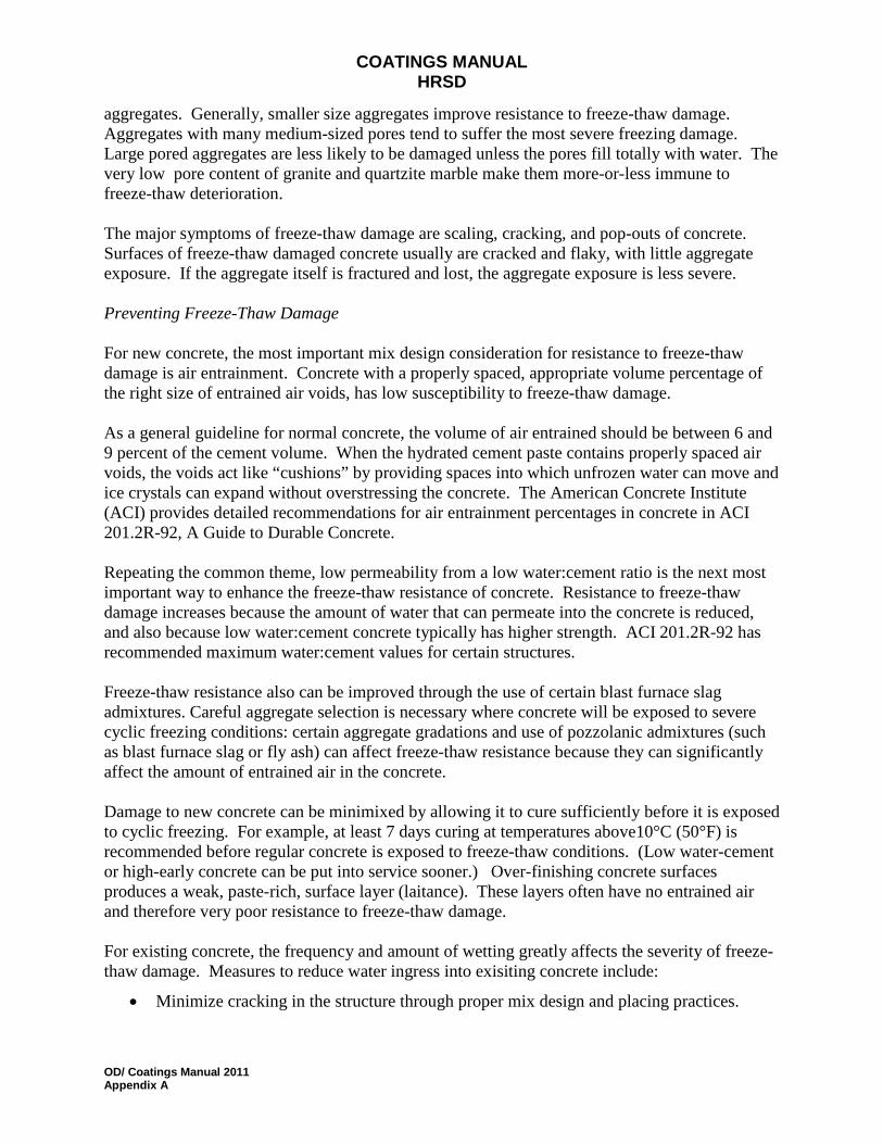
aggregates. Generally, smaller size aggregates improve resistance to freeze-thaw damage. Aggregates with many medium-sized pores tend to suffer the most severe freezing damage. Large pored aggregates are less likely to be damaged unless the pores fill totally with water. The very low pore content of granite and quartzite marble make them more-or-less immune to freeze-thaw deterioration. The major symptoms of freeze-thaw damage are scaling, cracking, and pop-outs of concrete. Surfaces of freeze-thaw damaged concrete usually are cracked and flaky, with little aggregate exposure. If the aggregate itself is fractured and lost, the aggregate exposure is less severe. Preventing Freeze-Thaw Damage For new concrete, the most important mix design consideration for resistance to freeze-thaw damage is air entrainment. Concrete with a properly spaced, appropriate volume percentage of the right size of entrained air voids, has low susceptibility to freeze-thaw damage. As a general guideline for normal concrete, the volume of air entrained should be between 6 and 9 percent of the cement volume. When the hydrated cement paste contains properly spaced air voids, the voids act like “cushions” by providing spaces into which unfrozen water can move and ice crystals can expand without overstressing the concrete. The American Concrete Institute (ACI) provides detailed recommendations for air entrainment percentages in concrete in ACI 201.2R-92, A Guide to Durable Concrete. Repeating the common theme, low permeability from a low water:cement ratio is the next most important way to enhance the freeze-thaw resistance of concrete. Resistance to freeze-thaw damage increases because the amount of water that can permeate into the concrete is reduced, and also because low water:cement concrete typically has higher strength. ACI 201.2R-92 has recommended maximum water:cement values for certain structures. Freeze-thaw resistance also can be improved through the use of certain blast furnace slag admixtures. Careful aggregate selection is necessary where concrete will be exposed to severe cyclic freezing conditions: certain aggregate gradations and use of pozzolanic admixtures (such as blast furnace slag or fly ash) can affect freeze-thaw resistance because they can significantly affect the amount of entrained air in the concrete. Damage to new concrete can be minimixed by allowing it to cure sufficiently before it is exposed to cyclic freezing. For example, at least 7 days curing at temperatures above10°C (50°F) is recommended before regular concrete is exposed to freeze-thaw conditions. (Low water-cement or high-early concrete can be put into service sooner.) Over-finishing concrete surfaces produces a weak, paste-rich, surface layer (laitance). These layers often have no entrained air and therefore very poor resistance to freeze-thaw damage. For existing concrete, the frequency and amount of wetting greatly affects the severity of freeze-thaw damage. Measures to reduce water ingress into exisiting concrete include:
• Minimize cracking in the structure through proper mix design and placing practices.
COATINGS MANUAL HRSD
OD/ Coatings Manual 2011 Appendix A
• Provide good drainage, avoid ponding and prevent underflow onto ceilings and soffits.
• Reduce the number of cold joints in the concrete.
• Use penetrating sealers, coatings, toppings, or other barriers to prevent water from permeating into the concrete.
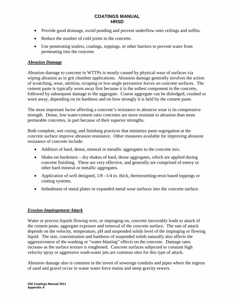
Abrasion Damage
Abrasion damage to concrete in WTTPs is mostly caused by physical wear of surfaces via wiping abrasion as in grit chamber applications. Abrasion damage generally involves the action of scratching, wear, attrition, scraping or low-angle percussive forces on concrete surfaces. The cement paste is typically worn away first because it is the softest component in the concrete, followed by subsequent damage to the aggregate. Coarse aggregate can be dislodged, crushed or worn away, depending on its hardness and on how strongly it is held by the cement paste. The most important factor affecting a concrete’s resistance to abrasive wear is its compressive strength. Dense, low water:cement ratio concretes are more resistant to abrasion than more permeable concretes, in part because of their superior strengths. Both complete, wet curing, and finishing practices that minimize paste segregation at the concrete surface improve abrasion resistance. Other measures available for improving abrasion resistance of concrete include:
• Addition of hard, dense, mineral or metallic aggregates to the concrete mix.
• Shake-on hardeners – dry shakes of hard, dense aggregates, which are applied during concrete finishing. These are very effective, and generally are comprised of emery or other hard mineral or metallic aggregates.
• Application of well designed, 1/8 –1/4 in. thick, thermosetting-resin based toppings or coating systems.
• Imbedment of metal plates or expanded metal wear surfaces into the concrete surface.
Erosion-Impingement Attack
Water or process liquids flowing over, or impinging on, concrete inexorably leads to attack of the cement paste, aggregate exposure and removal of the concrete surface. The rate of attack depends on the velocity, temperature, pH and suspended solids level of the impinging or flowing liquid. The size, concentration and hardness of suspended solids naturally also affects the aggressiveness of the washing or “water-blasting” effects on the concrete. Damage rates increase as the surface texture is roughened. Concrete surfaces subjected to constant high velocity spray or aggressive wash-water jets are common sites for this type of attack. Abrasion damage also is common in the invert of sewerage conduits and pipes where the ingress of sand and gravel occur in waste water force mains and steep gravity sewers.
COATINGS MANUAL HRSD
OD/ Coatings Manual 2011 Appendix A
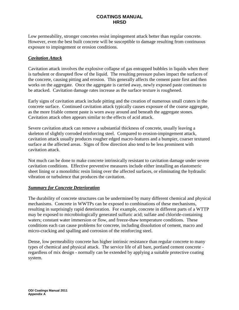
Low permeability, stronger concretes resist impingement attack better than regular concrete. However, even the best built concrete will be susceptible to damage resulting from continuous exposure to impingement or erosion conditions.
Cavitation Attack
Cavitation attack involves the explosive collapse of gas entrapped bubbles in liquids when there is turbulent or disrupted flow of the liquid. The resulting pressure pulses impact the surfaces of the concrete, causing pitting and erosion. This generally affects the cement paste first and then works on the aggregate. Once the aggregate is carried away, newly exposed paste continues to be attacked. Cavitation damage rates increase as the surface texture is roughened. Early signs of cavitation attack include pitting and the creation of numerous small craters in the concrete surface. Continued cavitation attack typically causes exposure of the coarse aggregate, as the more friable cement paste is worn away around and beneath the aggregate stones. Cavitation attack often appears similar to the effects of acid attack. Severe cavitation attack can remove a substantial thickness of concrete, usually leaving a skeleton of slightly corroded reinforcing steel. Compared to erosion-impingement attack, cavitation attack usually produces rougher edged macro-features and a bumpier, coarser textured surface at the affected areas. Signs of flow direction also tend to be less prominent with cavitation attack. Not much can be done to make concrete intrinsically resistant to cavitation damage under severe cavitation conditions. Effective preventive measures include either installing an elastomeric sheet lining or a monolithic resin lining over the affected surfaces, or eliminating the hydraulic vibration or turbulence that produces the cavitation.
Summary for Concrete Deterioration
The durability of concrete structures can be undermined by many different chemical and physical mechanisms. Concrete in WWTPs can be exposed to combinations of these mechanisms, resulting in surprisingly rapid deterioration. For example, concrete in different parts of a WTTP may be exposed to microbiologically generated sulfuric acid; sulfate and chloride-containing waters; constant water immersion or flow, and freeze-thaw temperature conditions. These conditions each can cause problems for concrete, including dissolution of cement, macro and micro-cracking and spalling and corrosion of the reinforcing steel. Dense, low permeability concrete has higher intrinsic resistance than regular concrete to many types of chemical and physical attack. The service life of all bare, portland cement concrete - regardless of mix design - normally can be extended by applying a suitable protective coating system.

COATINGS MANUAL HRSD
OD/ Coatings Manual 2011 Appendix A
D.
Metallic Corrosion Basics
Corrosion Fundamentals Corrosion of metals involves two balanced electrochemical reactions. The metal oxidizes, meaning that it loses at least one electron, and goes into ionic form, in the generic reaction:
M → M n+ + ne - The metal in question will be Fe in the most common metallic construction materials in wastewater environments - carbon steel (iron) ductile iron, and stainless steel. Zinc (Zn) may be present as the coating on galvanized steel. [The corrosion behavior of carbon steel and ductile iron are considered identical for the purposes of this discussion.] For the oxidation reaction to occur, one of the ionic chemical species present in the aqueous solution contacting the metal must be simultaneously reduced, meaning that it accepts one or more electrons and is converted to its reduced form. The overall corrosion reaction occurs only if both half-reactions can proceed and
if the resulting state of energy for the system is lower.
The two most common reduction reactions for aqueous environments are:
(i) Hydrogen ion reduction : 2H + + 2e - → H2 in acid solutions (pH < 5)
(ii) Oxygen reduction: O2 + 2H2O + 4e - → 4OH - in aerated, near-neutral waters, which typify most wastewaters.
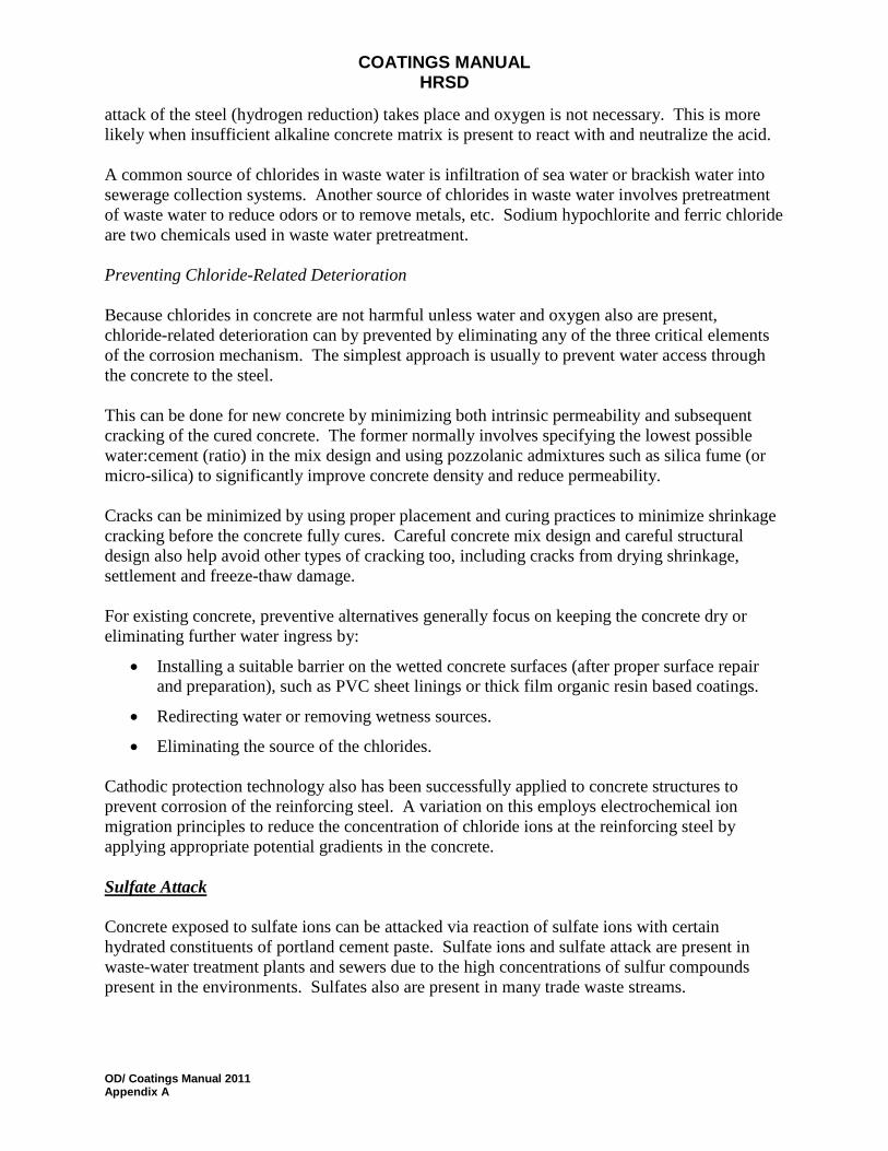
These reactions and the required flow of electrons through the metal are illustrated in Figure 2.
Figure 2Illustration of the electrochemical, oxidation and reduction half-reactions that must proceed at the same rate for corrosion to occur.
.

COATINGS MANUAL HRSD
OD/ Coatings Manual 2011 Appendix A
Corrosion can be prevented when either the oxidation reaction or reduction reaction is stymied. The most common method is to use a non-corroding, protective barrier (coating) to block the oxidation reaction. The barrier can be applied to the steel or can be a naturally-forming barrier if the alloy content of the steel is changed in certain ways, mostly by adding enough chromium to make the steel “stainless”. Stainless steels react with most aqueous environments to form an extremely thin, durable, insoluble oxide film that prevents continuing corrosion of the surface. Corrosion also can be prevented with electrochemical (cathodic) protection, which supplies electrons for the reduction reaction from an external source. The source can be from oxidation of a more reactive, “sacrificial” metal like zinc or magnesium, or from a separate DC power source connected to non-corroding anodes to “impress a current” onto the protected surfaces.
Commonly Used Metals Cast Irons, Carbon Steel And Stainless Steels
Carbon steel and ductile iron both corrode slowly in aerated wastewaters and more rapidly in locally acidified conditions caused by microbiological reactions. Corrosion rates in the normal aerated wastewater depend on the amount of aeration and to a lesser degree on the temperature. They seldom exceed 10 mpy (0.25 mm/y). This is relatively slow, but is high enough that carbon steel requires continual maintenance to achieve the long service life normally expected from pipes and other wastewater equipment, especially inside wastewater treatment plants. Corrosion rates of carbon steel and iron in wastewater can be accelerated 5 to 10 fold by local acidic conditions produced by microbiological action. Furthermore, pipes and other structure made from carbon steel and ductile iron can be externally corroded by the surrounding soil. This demonstrates why unprotected carbon steel and ductile iron are not suitable for long-term wastewater service or, for that matter, for any natural water service. Even steel ships and bridges must be painted or cathodically protected to prevent gradual deterioration. On the other hand, the relatively low corrosiveness and generally moderate temperatures of typical wastewater service environments - excepting when warm solutions with high concentrations of sulfur species arise in activated sludge digestion; acids formed by biological reactions, or when brackish water is involved - means that many other metals and non-metal materials also can provide cost-effective corrosion resistance. In addition, carbon steel and ductile iron can be protected with appropriate coatings and linings. However, because it costs money to maintain almost every type of protective barriers against damage and gradual deterioration, metallic materials that do not require addition of a protective barrier are often more cost-effective over the long term. The most obvious candidate materials for “corrosion-free” service in wastewaters are the common, “low-end” stainless steels. [The development of stainless steels and five “families” of stainless steels are summarized below.]
COATINGS MANUAL HRSD
OD/ Coatings Manual 2011 Appendix A
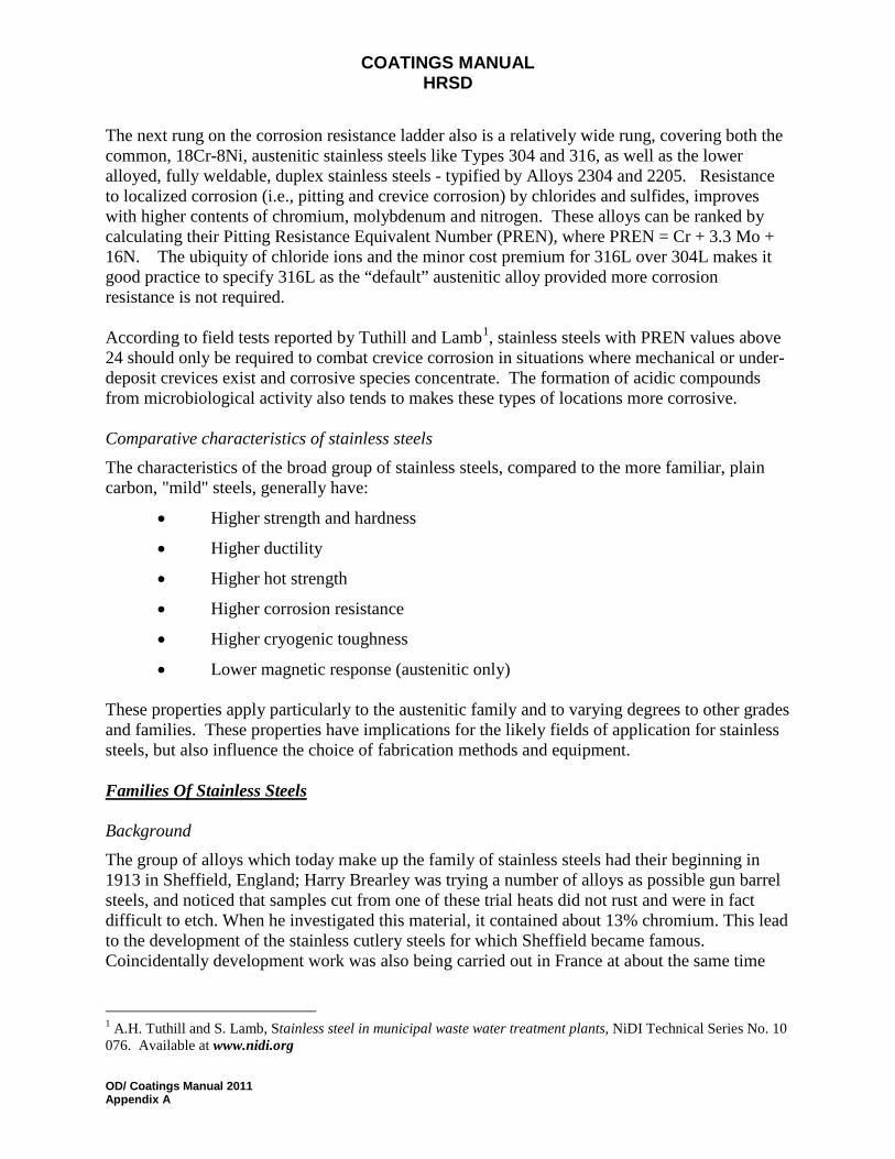
The next rung on the corrosion resistance ladder also is a relatively wide rung, covering both the common, 18Cr-8Ni, austenitic stainless steels like Types 304 and 316, as well as the lower alloyed, fully weldable, duplex stainless steels - typified by Alloys 2304 and 2205. Resistance to localized corrosion (i.e., pitting and crevice corrosion) by chlorides and sulfides, improves with higher contents of chromium, molybdenum and nitrogen. These alloys can be ranked by calculating their Pitting Resistance Equivalent Number (PREN), where PREN = Cr + 3.3 Mo + 16N. The ubiquity of chloride ions and the minor cost premium for 316L over 304L makes it good practice to specify 316L as the “default” austenitic alloy provided more corrosion resistance is not required. According to field tests reported by Tuthill and Lamb1
, stainless steels with PREN values above 24 should only be required to combat crevice corrosion in situations where mechanical or under-deposit crevices exist and corrosive species concentrate. The formation of acidic compounds from microbiological activity also tends to makes these types of locations more corrosive.
Comparative characteristics of stainless steels The characteristics of the broad group of stainless steels, compared to the more familiar, plain carbon, "mild" steels, generally have:
• Higher strength and hardness
• Higher ductility
• Higher hot strength
• Higher corrosion resistance
• Higher cryogenic toughness
• Lower magnetic response (austenitic only) These properties apply particularly to the austenitic family and to varying degrees to other grades and families. These properties have implications for the likely fields of application for stainless steels, but also influence the choice of fabrication methods and equipment.
Families Of Stainless Steels
Background The group of alloys which today make up the family of stainless steels had their beginning in 1913 in Sheffield, England; Harry Brearley was trying a number of alloys as possible gun barrel steels, and noticed that samples cut from one of these trial heats did not rust and were in fact difficult to etch. When he investigated this material, it contained about 13% chromium. This lead to the development of the stainless cutlery steels for which Sheffield became famous. Coincidentally development work was also being carried out in France at about the same time
1 A.H. Tuthill and S. Lamb, Stainless steel in municipal waste water treatment plants, NiDI Technical Series No. 10 076. Available at www.nidi.org

COATINGS MANUAL HRSD
OD/ Coatings Manual 2011 Appendix A
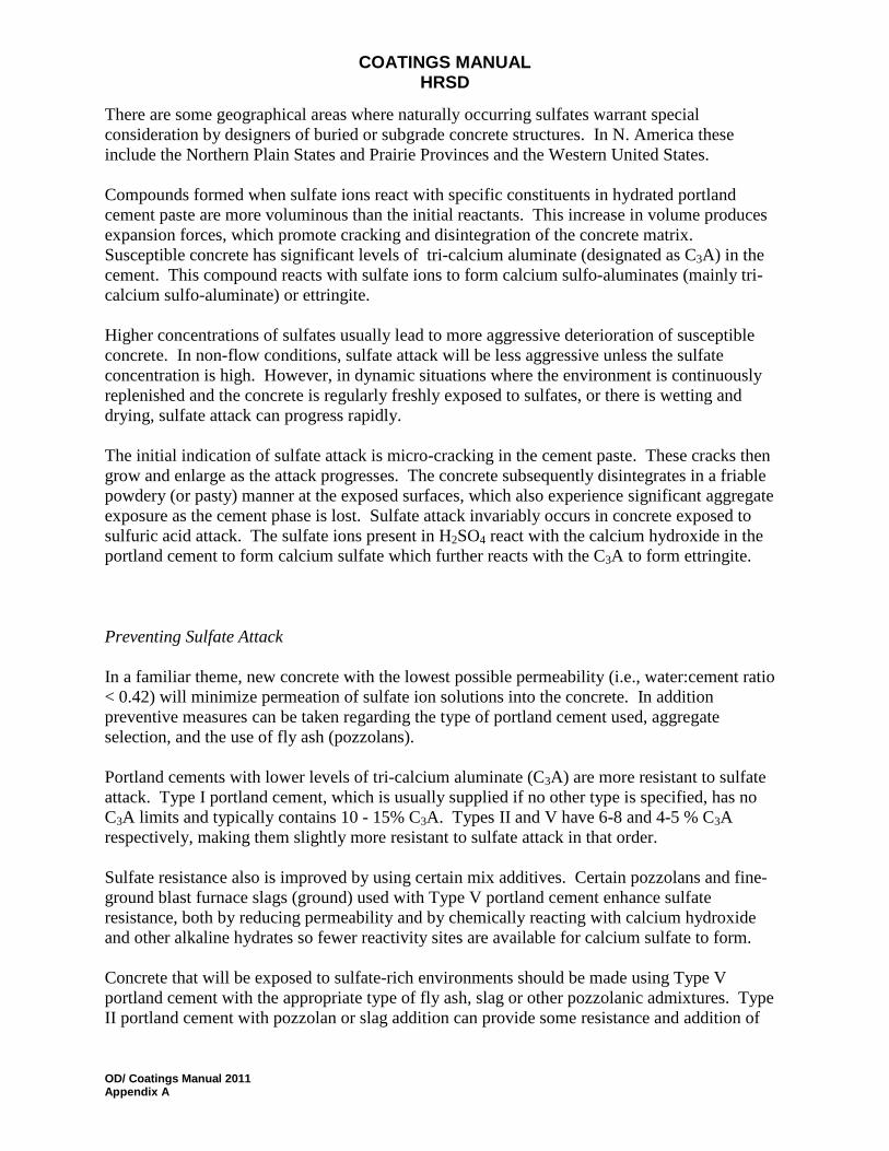
which culminated in the production of the first austenitic stainless steels, which contained both nickel and chromium. The worldwide consumption of stainless steel is increasing. Stainless steel is used in the building and construction industry for its attractive appearance, corrosion resistance, low maintenance and strength. Many other industries use stainless steel for similar reasons, as well as for the fact that it does not need to be treated, coated or painted when put into service, despite the fact that it is more expensive than plain carbon steels. Stainless steels are iron-based alloys containing a minimum of about 10.5% chromium; this forms a protective self-healing oxide film, which is the reason why this group of steels has their characteristic "stainless” nature or corrosion resistance. The ability of the oxide layer to heal itself means that the steel is corrosion resistant no matter how much of the surface is removed. This is not the case when carbon or low alloy steels are protected from corrosion by metallic coatings, such as zinc, chromium or nickel, or by organic coatings, such as paint. Although all stainless steels depend for their superior corrosion resistance on the presence of chromium, other alloying elements are often added to enhance their properties. These alloying additions influence the metallurgical microstructure of the alloys, which are categorized into “families” primarily on the basis of the metallurgical structure. The microstructure is defined by the arrangement of the atoms that make up the grains of the steel and that can be seen when a polished surface of the steel is viewed at high magnification through a metallurgical microscope. Depending upon the exact chemical composition of the steel, the microstructure may be made up of the stable metallurgical phases “austenite” or “ferrite”; a "duplex" combination of these two phases; the hard, crystallographically distorted, “martensite” phase created when some steels are rapidly quenched from a high temperature, or an austenitic structure hardened in the solid state by precipitated micro-constituents. Figure 3 shows the relationships between the different families based on their chromium and nickel contents.
Figure 3Families of stainless steels, based on the Ni and Cr contents.
.
COATINGS MANUAL HRSD
OD/ Coatings Manual 2011 Appendix A
Austenitic Stainless Steels This group contains at least 16% chromium and 6% nickel (the basic grade 304 is referred to as 18/8) and range through to the high alloy or "super austenitics" such as 904L and 6% molybdenum grades. Additional elements can be added such as molybdenum, titanium or copper, to modify or improve their properties, making them suitable for many critical applications involving high temperature as well as corrosion resistance. This group of steels is also suitable for cryogenic applications because the effect of the nickel content in making the steel austenitic avoids the problems of brittleness at low temperatures, which is a characteristic of other types of steel. Ferritic Stainless Steels These are plain chromium (10.5 to 18%) grades such as Grade 430 and 409. Their moderate corrosion resistance and poor fabrication properties are improved in the higher alloyed grades such as Grades 434 and 444. Weldable ferritic 12Cr stainless steels, including proprietary alloys 3CR12 (UNS S40977 and S41003) and 409Ni, make up the lowest practical rung on the alloy “ladder” based on corrosion resistance. 3CR12 and its kin are effective in many applications where carbon steel, galvanised, aluminised or painted steel or aluminium give unsatisfactory life. It is not attacked by alkalies and often gives adequate resistance in acidic conditions. 3CR12 resists chloride stress corrosion cracking. However, it is less resistant than Type 304 to pitting and crevice corrosion in chloride environments. These “utility” stainless steels readily resist water with chloride contents of up to 200 mg/L at ambient temperatures and the presence of sulphate or nitrate ions reduces the corrosivity of chlorides. Light surface rust formed in some atmospheres makes these grades less suitable than the 18-8 grades for decorative applications. The slightly higher strengths of these alloys and the possible need for a smaller corrosion allowance can make thinner sections necessary for the same design loading. They especially outperform carbon steels - even hardened versions in wet abrasion service. Logical uses for these stainless steels include sluice gates; air piping or other components immersed in wastewaters; slide rails in settling basins; clarifier weirs; sludge chutes and piping, etc. Martensitic stainless steels Martensitic stainless steels also have chromium as the major alloying element, but have higher carbon and generally lower chromium contents (e.g. 12% in Grade 410 and 416) than the ferritic types; Grade 431 has a chromium content of about 16%, but the microstructure is still martensite despite this high chromium level because this grade also contains 2% nickel. Duplex stainless steels Duplex stainless steels offer an outstanding combination of corrosion resistance and strength. Duplex stainless steels such as 2304 and 2205 (the designations indicate compositions of 23% Cr - 4% Ni and 22% Cr - 5% Ni, plus further minor alloying additions) have microstructures
COATINGS MANUAL HRSD
OD/ Coatings Manual 2011 Appendix A
comprised of a mixture of austenite and ferrite. Their duplex microstructure makes these steels resistant to stress corrosion cracking, albeit not quite as resistant as the ferritic steels and their strength is greater than that of the (annealed) austenitic steels, by a factor of about two. Duplex steels have general corrosion resistance equal to or better than 304 and 316, and, in general, their pitting corrosion resistances are equivalent to 316 for 2304 and superior to 316 for 2205. (PRENs for 2304 and 2205 are 24 and 34 respectively.) The duplex steels suffer reduced toughness below about –50°C and after exposure above 350°C, so are used between these temperatures. Duplex stainless steels have good weldability, albeit not quite as good as that of the austenitics. All the usual processes can be used and a range of consumables is available. For the most common duplex grade 2205, the standard consumable is a 2209 - the higher nickel content ensures the correct 50/50 ferrite/austenite structure in the weld deposit, thus maintaining strength, ductility and corrosion resistance. 309 is also widely used. Unlike the austenitic stainless steels, the coefficient of thermal expansion of duplex stainless steels closely matches that of carbon steels. Precipitation Hardening Stainless Steels These are chromium and nickel containing steels that can develop very high tensile strengths. The most common grade in this group is "17-4 PH", also known as Grade 630, with the composition of 17% Cr, 4% Ni, 4% Cu and 0.3% Nb. These steels can be supplied in the "solution treated" condition, in which condition the steel is machineable. Following machining, forming etc. the steel can be strengthened/hardened by a single, fairly low temperature "ageing" heat treatment, which causes no distortion of the component.
Aluminum Alloys
Aluminum alloys also perform adequately if the exposure conditions remain within relatively narrow bounds of pH, around neutral. General properties Aluminum is a light-weight metal with a density approximately one-third that of carbon steel. Aluminum alloys are available in wrought and cast form. The mechanical properties of relatively pure Al are of the order 16 ksi tensile strength and 6 ksi yield strength. The strength can be improved by strain hardening (cold-working); by alloying, by heat-treatment, or a combination of these. Copper magnesium, manganese silicon and zinc are the major alloying constituents. The amount of alloying element defines the type of Al alloy. Alloys used in process and other industries where strength is not the primary requirement seldom are stronger than 45 ksi tensile strength and 40 ksi yield strength (e.g. A96061- T6). The general format for UNS numbering of Al alloys is A9xxxx for wrought alloys and A0xxxx for castings. The second digit indicates the major alloying constituent: 1 for a Al only; 2 for copper; 3 for manganese; 4 for silicon; 5 for magnesium; 6 for magnesium and silicon; 7 for zinc, and 8 for miscellaneous. For example A92xxx is an aluminum-copper alloy. The third

COATINGS MANUAL HRSD
OD/ Coatings Manual 2011 Appendix A
digit indicates whether there are controls on impurities and the last two digits are arbitrary holdovers from the earlier Aluminum Association alloy numbering system. Wrought alloys most often used in chemical process service are A91100, A93003, A95086, A95154 and A96061. A suffix system is used to indicate the condition of the alloy:
O - indicates annealed to the softest condition.
F - indicates “as fabricated”, with no control over strain hardening or thermal conditions.
H - indicates the alloy is strain hardened (there are 3 levels).
T - indicates the alloy is hardened by heat treatment or tempering, with or without
supplementary strain hardening (there are 10 types).
Aluminum has excellent low temperature properties, with high ductility in cryogenic service.
Table 1. UNS Numbering for Aluminum Alloys Alloy No. Example Major Alloy Elements
A91xxx A91100 None (99.00% alum. min.)
A92xxx A92020 Copper
A93xxx A93003 Manganese
A94xxx A94002 Silicon
A95xxx A95154 Magnesium
A96xxx A96063 Magnesium and silicon
A97xxx A97001 Zinc, with copper or magnesium
A98xxx A98013 Miscellaneous (chromium)
Aluminum and its alloys can be welded by most of the common welding methods. Welding with GMAW and GTAW processes is most common, although SMAW (stick electrode) is practicable and provides acceptable welds. The heat input from welding changes the properties of hardened alloys in the heat-affected zone. The A95xxx (magnesium) alloys have excellent weldability, but the A92xxx (copper) alloys and A97xxx (zinc/copper) alloys are not recommended for fusion welding.
COATINGS MANUAL HRSD
OD/ Coatings Manual 2011 Appendix A
Corrosion of aluminum alloys General Corrosion
Aluminum is amphoteric - it corrodes in both acid and alkali solutions. However, the protective oxide film formed in neutral, oxidizing solutions gives Al and its alloys good corrosion resistance in many natural waters and in uncontaminated atmospheres. (Al also has good resistance to many hot gas environments.) Copper-bearing alloys, specifically those with more than 2.5% copper, are not suitable for industrial use where high corrosion resistance is needed. (The presence of copper on the surface accelerates corrosion of the aluminum regardless of how the copper gets there.) Pitting corrosion of all aluminum alloys can occur in stagnant solutions containing chlorides.
In Natural Waters
Unalloyed Al corrodes at less than one mpy in high-purity waters in the pH range of 4.5 to 9, at temperatures up to 100C. The most important factors controlling corrosion of aluminum alloys in natural waters are temperature, pH, water conductivity, presence of heavy metal ions, oxidizing power of the water and the flow conditions. Alloys of the A91xxx, A93xxx, A95xxx, and A96xxx series have suitable corrosion resistance for many natural waters.
In Seawater
A91xxx, A93xxx, A95xxx and A96xxx alloys have good corrosion resistance in seawater applications and are widely used for partial, intermittent or complete immersion. Cast alloys of the A0356.0 and A0514.0 types also have high resistance to seawater corrosion.
General corrosion rates in seawater are very low, especially for A95xxx and A93xxx alloys. The main form of corrosion is pitting and crevice corrosion which can penetrate at up to 0.2 mpy. (also very slow). A96xxx alloys are acceptable but corrode 2 - 3 times faster than A95xxx alloys and experience more aggressive pitting.
Copper-containing alloys (A92xxx and A97xxx) are normally not used without supplementary protection - protective coatings of aluminum cladding, thermal spray or paint. Al alloys are subject to marine bio-fouling. Common Corrosion Problems In Waters
Corrosion of aluminum and its alloys in natural waters is usually caused by:
The presence of harmful metal ions in solution - copper, lead, mercury and nickel being the main culprits. Harmful ions may be present in low levels in natural and waste waters and levels as low as a few parts per million can cause harmful effects.
Galvanic coupling to more noble metals, such as carbon steel, stainless steel or copper. Aluminum is anodic to all common metals except zinc and magnesium, so special steps should be taken to ensure it does not inadvertently end up cathodically protecting other
COATINGS MANUAL HRSD
OD/ Coatings Manual 2011 Appendix A
metal components. In some cases, the reinforcing steel in concrete structures can unwittingly be a cathode.
Crevice corrosion, especially at faying surfaces or crevices between concrete and imbedded aluminum.
Pitting in stagnant, contaminated or saline solutions. Environmental cracking is only a problem in heat treated, high strength alloys. For example, A97075- T6 is susceptible to stress corrosion cracking (SCC). However, the same alloy with the T73 heat-treatment is has good resistance to environmental cracking. SCC of aluminum alloys is characteristically intergranular. This makes heavily wrought components (with severely distorted grains) less susceptible to SCC if the stresses act parallel to the elongated grains, and vice versa. Protective coatings Pure aluminum and the 3xxx, 5xxx and 6xxx alloys can be used in industrial atmospheres and waters without protective coatings, which are often used to ensure predictable appearance for architectural use. The most resilient and effective protective coating is an electrolytically-induced aluminum oxide film formed in a process called anodizing. Anodizing and anodized coatings are a subject on their own and are not covered here. Because anodizing cannot be relied on to protect corrosion-susceptible alloys, supplementary protection with protective coatings is normally required. Fortunately, the anodized film is a good base for organic protective coatings, although the surface preparation instructions of the coating manufacturer always should be carefully followed.