Basic products -OWNER’S MANUAL- - Candock · INSIDE P.6 G2 SERVICE CUBE ( REGULAR, TRANSLUCENT...
12
ARE YOU READY TO -OWNER’S MANUAL- Modular floating systems Basic products www.candock.com [email protected] 9441, Bourque Blvd. Sherbrooke (Qc) J1N 0G2 OFFICE|BUR. T.FREE|S. FRAIS FAX|TÉLÉC. 819 847-2599 1 888 547-2599 819 847-3250
Transcript of Basic products -OWNER’S MANUAL- - Candock · INSIDE P.6 G2 SERVICE CUBE ( REGULAR, TRANSLUCENT...
ARE YOU READY TO
-OWNER’S MANUAL-
Modular floating systems
Basic products
www.candock.com [email protected]
9441, Bourque Blvd.Sherbrooke (Qc) J1N 0G2
OFFICE|BUR. T.FREE|S. FRAIS FAX|TÉLÉC.
819 847-25991 888 547-2599
819 847-3250

Modular floating systems
www.candock.com [email protected]
9441, Bourque Blvd.Sherbrooke (Qc) J1N 0G2
OFFICE|BUR. T.FREE|S. FRAIS FAX|TÉLÉC.
819 847-25991 888 547-2599
819 847-3250
TABLE OF CONTENT
G2 CUBE + G2 LOW PROFILE CUBE
G2 ROWING CUBE
G2 EDGE CUBE
G2 CORNER CUBE
G2 SERVICE CUBE
G2 CONNECTING PIN
CANDOCK SLIDING NUT
CANDOCK LUG CONNECTOR
CANDOCK NUT
CANDOCK SPACER
P.2
P.4
P.
P.5
P.6
P.8
P.9
P.10
P.11
P.12
*The following instructions are guidelines to be followed. Candock will not be responsible for damages incured by the non-compliance to these guide lines. All distributors are required and responsible to provide theoretical and practical training to clients on the completeuse of the different dock systems. Candock inc. can not be held responsible in any way for any damages resulting from the fact that the client has not received adequate training.
P.1
*** Note that it is preferable to consult the manual on a COLORED printed version, or directly on your computer screen***

PRIOR TO INSTALLATION
*During the installation of a dock, always have the plugs oriented towards the shore. This orientation will simply use less CANDOCK SPACERS and will improve the aesthetic of your dock. (*If your configuration is meant to go along the shore line instead of off-shore, align plugs towards the shortest side of your dock)
**Always make sure to regroup 4 different tabs height to complete your assembly. Make sure they are in their pre-destined position andthat none of these are wrongly placed.
***Preassemble the dock in larger sections directly on the ground. When in water, prepare the missing units of G2 CONNECTING PINS and CANDOCK SLIDING NUTS and position on the corresponding side of each sections. This will help you save time.
Modular floating systems
www.candock.com [email protected]
9441, Bourque Blvd.Sherbrooke (Qc) J1N 0G2
OFFICE|BUR. T.FREE|S. FRAIS FAX|TÉLÉC.
819 847-25991 888 547-2599
819 847-3250
G2 CUBE + G2 LOW PROFILE CUBE
Available colors are GREY, BEIGE and BLUEOther colors also available upon special request.
Material/Composition :High-density polyethylene resin
Surface :Anti-skid
Dimensions :L x W : 48 cm (19”) x 48 cm (19”)H : 36 cm (14”)
Dimensions (low profile cube) :L x W : 48 cm (19”) x 48 cm (19”)H : 23 cm (9”)
Floating capacity :Cube: 68 kg (150 lbs.) per cubeor 272 kg per sq. m. (60 lbs. per sq. ft.)Low profile cube : 50 kg (110 lbs.) per cubeor 210 kg per sq. m. (44 lbs. per sq. ft.)
Weight :Cube: 5.5 kg (12 lbs.)Low profile cube : 5 kg (11 lbs.)
Needed tools :G2 key for pin “combo-pack”Key for nutorRatchet key for nut + ratchet tool
TABS: Prominent grooved parts of the cube, which are located at different heights on each of the 4 corners of the “cube” (tab #1 to #4, #1 being the lowest and #4, the highest). These tabs are an integral part of the Candock system. When ralied in groups of 4, the cubes create a larger square. At the center of this square, 4 different tabs overlap each other. These tabs form a single opening and are meant to be coupled with our CANDOCK SLIDING NUT and G2 CONNCETING PIN to form a unique structure.
PLUGS: These watertight plugs are always found on the side of the cube that is between tab # 1 and # 4. These same plugs, made of breathable material, act as pressure release valves thus preventing any cube deformation which is due to temperature or altitude.Furthermore, these plugs prevent any condensation inside the cube.
TERMINOLOGY
ASSEMBLY PROCEDURE
With the use of the provided tools, proceed following these few steps:
ORIENTATION OF TABS
P.2
#4
#1

Modular floating systems
www.candock.com [email protected]
9441, Bourque Blvd.Sherbrooke (Qc) J1N 0G2
OFFICE|BUR. T.FREE|S. FRAIS FAX|TÉLÉC.
819 847-25991 888 547-2599
819 847-3250
ASSEMBLY PROCEDURE
PROCEDURE:
1- Prepare all items (basic products such as : G2 CUBES, G2 CONNECTING PINS and CANDOCK SLIDING NUTS) and have them unboxed close to your “assembly” area.
2- Place the CANDOCK SLIDING NUTS on the lower tabs (usually #1) .
3- Position the sections next to each other and ensure that the tabs are positioned correctly.
4- Insert the G2 CONNECTING PINS in the tabs and screw-in using the proper tooling.
5- If necessary, place CANDOCK LUG CONNECTORS and CANDOCK NUTS on empty tabs on the perimter of your dock. If necessary, do not forget to fill the space between the tabs with CANDOCK SPACERS.
TIPS
While assembling bigger sections on water, place a G2 CONNECTING PIN, as shown on the picture. Then bring the two sections side by side while making sure that the tabs properly overlap each other. Then insert the missing pins. This technique will help you assemble big sections with ease.
THE SCISSOR TECHNIQUE
G2 CONNECTING PIN SLIDING NUT
P.3
*
*On “inside” corners,make sure to includethe needed G2 CONNECTING PIN andSLIDING NUT. The later simplygoes on the lowest tabavailable.

Modular floating systems
www.candock.com [email protected]
9441, Bourque Blvd.Sherbrooke (Qc) J1N 0G2
OFFICE|BUR. T.FREE|S. FRAIS FAX|TÉLÉC.
819 847-25991 888 547-2599
819 847-3250
G2 ROWING CUBES
Available colors are GREY, BEIGE and BLUEOther colors also available upon special request.
Material/Composition :High-density polyethylene resin
Surface :Anti-skid
Dimensions :L x W : 48 cm (19”) x 48 cm (19”)H : 23 cm (9”)
Freeboard :17 cm (7”) under dead load 5 cm (2.5”) under live load**100kg / sq.meteror*20.35lbs/sq.feet
Floating capacity :Variable
Weight :5 kg (11 lbs.)
Needed tools :G2 key for pin “combo-pack”Key for nutorRatchet key for nut + ratchet tool
Certification/Approval
CAVITY: Specially designed cavity located in center of the bottom face of the cube. This recess is intended to optimize freeboard height, (in regards with FISA regulations) between 2 and 7 inches (5 to 18 cm), depending on applied load (18 cm when under “DEAD LOAD” and 5 cm under “LIVE LOAD” ( 100kg / sp. meter )). Furthermore, this cavity is increasing the overall stability of the product when in use.
STABILIZATION BARS: Custom designed aluminum stiffening beams limiting overall inclination of our systems when they are destined to large scale competition installations and infrastructures. When properly fixed underneath G2 ROWING CUBE platforms, these aluminum beams prevent the platform’s outskirts from plunging excessively in the water when groups of competitors (rowers) are walking on the edge of the platforms.
TERMINOLOGY (also see G2 CUBE terminology)
ASSEMBLY PROCEDURE
P.4
http://www.worldrowing.com/fisa/
Refer to the G2 CUBE assembly procedure.
NOTE
If the product is destined to a major competition infrastructure, make sure to use the required STIFFENING BEAMS.For additionnal support, please contact our main offices at [email protected].
Modular floating systems
www.candock.com [email protected]
9441, Bourque Blvd.Sherbrooke (Qc) J1N 0G2
OFFICE|BUR. T.FREE|S. FRAIS FAX|TÉLÉC.
819 847-25991 888 547-2599
819 847-3250
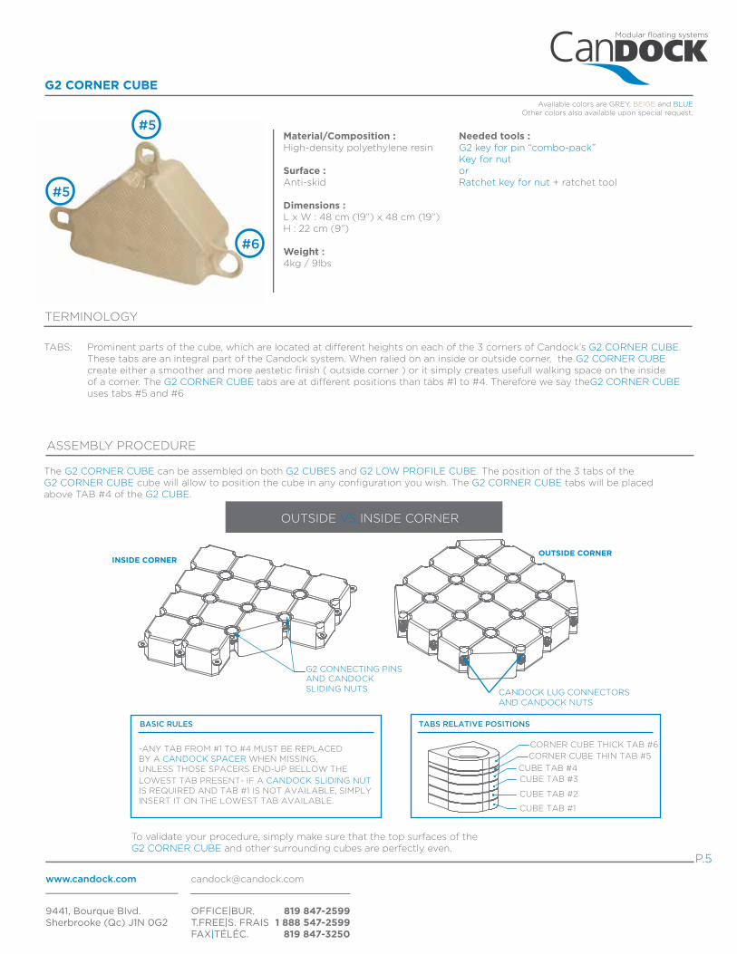
G2 CORNER CUBE
Available colors are GREY, BEIGE and BLUEOther colors also available upon special request.
TERMINOLOGY
ASSEMBLY PROCEDURE
The G2 CORNER CUBE can be assembled on both G2 CUBES and G2 LOW PROFILE CUBE. The position of the 3 tabs of the G2 CORNER CUBE cube will allow to position the cube in any configuration you wish. The G2 CORNER CUBE tabs will be placed above TAB #4 of the G2 CUBE.
Material/Composition :High-density polyethylene resin
Surface :Anti-skid
Dimensions :L x W : 48 cm (19”) x 48 cm (19”)H : 22 cm (9”)
Weight :4kg / 9lbs
TABS: Prominent parts of the cube, which are located at different heights on each of the 3 corners of Candock’s G2 CORNER CUBE. These tabs are an integral part of the Candock system. When ralied on an inside or outside corner, the G2 CORNER CUBE create either a smoother and more aestetic finish ( outside corner ) or it simply creates usefull walking space on the inside of a corner. The G2 CORNER CUBE tabs are at different positions than tabs #1 to #4. Therefore we say theG2 CORNER CUBE uses tabs #5 and #6
#5
#5
P.5
#6
CORNER CUBE THICK TAB #6
CUBE TAB #4CUBE TAB #3
CUBE TAB #2
CUBE TAB #1
TABS RELATIVE POSITIONS
CORNER CUBE THIN TAB #5
CANDOCK LUG CONNECTORS AND CANDOCK NUTS
OUTSIDE CORNER
G2 CONNECTING PINSAND CANDOCK SLIDING NUTS
INSIDE CORNER
To validate your procedure, simply make sure that the top surfaces of the G2 CORNER CUBE and other surrounding cubes are perfectly even.
-ANY TAB FROM #1 TO #4 MUST BE REPLACED BY A CANDOCK SPACER WHEN MISSING, UNLESS THOSE SPACERS END-UP BELLOW THE
LOWEST TAB PRESENT- IF A CANDOCK SLIDING NUT IS REQUIRED AND TAB #1 IS NOT AVAILABLE, SIMPLY INSERT IT ON THE LOWEST TAB AVAILABLE.
OUTSIDE VS INSIDE CORNER
BASIC RULES
Needed tools :G2 key for pin “combo-pack”Key for nutorRatchet key for nut + ratchet tool

Modular floating systems
www.candock.com [email protected]
9441, Bourque Blvd.Sherbrooke (Qc) J1N 0G2
OFFICE|BUR. T.FREE|S. FRAIS FAX|TÉLÉC.
819 847-25991 888 547-2599
819 847-3250
INSIDE
P.6
G2 SERVICE CUBE ( REGULAR, TRANSLUCENT AND SIDE COVER )
Available colors are GREY, BEIGE.Other colors also available upon special request.
Options:
BASE: Lower part of the G2 SERVICE CUBE specially designed to host SERVICE COVERS.
COVER: Upper part of the G2 SERVICE CUBES allowing water and electricty lines to be passed directly inside the cubes. Available in 2 different models ( REGULAR COVER or SIDE COVER ) to ensure easy installation even when installed on the outside limits of our system. Equipped with a custom moulded hinge, our SIDE COVER model is extremely easy to ATTACH. Please make sure to use proper hardware when using the SIDE COVER. Both REGULAR COVERS and SIDE COVERS are available in a translucent finish. This option offers the same capabilities as the OPAQUE COVERS while beeing specially designed to be equiped with our custom built L.E.D. LIGHT SYSTEMS. For additionnal information, please see the ACCESSORY OWNER’S MANUAL.
TERMINOLOGY
ASSEMBLY PROCEDURE ( refer to the G2 CUBES assembly procedure )
With the use of the provided tools, proceed with these key steps:
PRIOR TO INSTALLATION
*REGULAR COVER
If G2 SERVICE CUBE is surrounded by regular G2 CUBES, we suggest you assemble them witout the covers. The process of passing the water and electricity lines should be scheduled once the overall layout is completed.
**SIDE COVER
If G2 SERVICE CUBES are to be installed on the outskirt of the dock, make sure to attach the SIDE COVERS prior to assembly. Proceed carefully to prevent striping the inserts treads.The process of passing the water and electricity lines should be scheduled once the overall layout is completed and will remain extremely simple. Make sure to screw the bottom part of the HINGE on the outskirt side of the cubes.
***Make sure to configure the G2 SERVICE CUBE layout in a way that will necessitate as less cables and electric lines as possible. Make sure to optimize closed AND opên circuits.
Regular / Beige
Side cover / TranslucentSide cover / Grey
Regular / TranslucentRegular / Grey
Side cover / Beige
Needed tools :-G2 key for pin “combo-pack”-Key for nutor-Ratchet key for nut + ratchet tool-#6 Halen key-7/16” ratchet key + ratchet tool

Modular floating systems
www.candock.com [email protected]
9441, Bourque Blvd.Sherbrooke (Qc) J1N 0G2
OFFICE|BUR. T.FREE|S. FRAIS FAX|TÉLÉC.
819 847-25991 888 547-2599
819 847-3250
P.7
WATER AND ELECTRICITY LINE INSTALLATION PROCEDURE (INSIDE THE DOCK)
1) Assemble the dock as usual without the COVERS.
2) Make sure not to tighten the pins adjacent to the service bases all the way as you will need to unscrew them.
3) This will leave a safe and clear path for your services.
4) Lay down all your service lines.
5) Start from one extremity and install the covers as you go.
6) Unscrew the pins enough in between 2 COVERS so that you can slide them in without removing the pins completely.
7) Once you have a few COVERS in, start tightening some pins so that the dock does not become too lose.
8) Continue the process.
WATER AND ELECTRICITY LINE INSTALLATION PROCEDURE (ON THE OUTSKIRT OF THE DOCK)
1) Assemble the dock as usual without the COVERS.
2) Make sure not too tight the pins adjacent to the service bases all the way as you will need to unscrew them.
3) This will leave a safe and clear path for your services.
4) Lay down all your service lines.
5) Install all the hinges on the bases. (see instructions on page 6)
6) Start from one extremity and install the COVERS as you go.
7) You will have to unscrew the pins a lot to be able to close the cover. Since you are on the edge of the dock this might leave the cube free of moving away from the dock. Trick, just insert a temporary pin on the perimeter tabs of the cubes you are working on.
8) Once you have a few covers in, start tightening some pins so that the dock does not become too lose.
9) Continue the process.
TIP: Electric cables and flexible pipes may also be fished underneath the covers with a long pole.

Modular floating systems
www.candock.com [email protected]
9441, Bourque Blvd.Sherbrooke (Qc) J1N 0G2
OFFICE|BUR. T.FREE|S. FRAIS FAX|TÉLÉC.
819 847-25991 888 547-2599
819 847-3250
P.8
G2 CONNECTING PIN
Available colors are GREY, BEIGE and BLUEOther colors also available upon special request.
Material/Composition :High-density polyethylene resin
Surface :Flat & Anti-skid
Dimensions :L : 24 cm (9.6”) x W: 17.2 cm (6.88”)Shaft diameter : 4.547 cm (1.819”)
Wall thickness:.0750 cm (0.300”)
Strength :Vertical pull when coupled to a complete G2 CUBE assembly (4 cubes) and a SLIDING NUT:
over 1136kg (2500lbs)
Needed tool :-G2 key for pin “combo-pack”
HEAD: Upper part of the G2 CONNECTING PINS designed with a flat and anti-skid surface. Surrounded by 2 notches that are needed to operate the KEY FOR G2 PIN “COMBO PACK” or regular KEY FOR G2 PIN.
NOTCH: Manufactured recess in the pin’s head used to insert the key for screwing and unscrewing.
SHAFT: Male part of our coupling system, the treaded shaft is to be inserted in our CANDOCK SLIDING NUTS.
TERMINOLOGY
ASSEMBLY PROCEDURE
1-During assembly process, always initiate the screwing process by hand. By doing so, pre-mature wear and tear will be prevented.
2-When the pins are properly inserted, proceed by screwing manually and/or mechanically with our pre-destined tools. Either the KEY FOR G2 PIN “COMBO PACK” or the regular G2 KEY FOR PINS (manual or drill) can be used.
3-Make sure to securely tighten the G2 CONNECTING PINS until snug, without over tightening them.
-When initially inserting the G2 CONNECTING PINS in place, you might want to firmly “tap” the PIN in place. By proceeding so, you will ensure a strong “initial” grip of the shaft treads into the CANDOCK SLIDING NUT. Likewise this “tap” will help you get the pin through the 4 cube tabs resting on top of the CANDOCK SLIDING NUT.
-Once the assembly process is completed, align the NOTCHES of every G2 CONNECTING PINS using the manual key. This simple operation will allow to quickly locate any G2 CONNECTING PINS which could have unscrewed over time. Furthermore, the aesthetic of your dock will be enhanced.
-Always proceed with caution if using a power drill to fasten the G2 CONNECTING PINS, the drill can have tendency to “kick”. Use protective footwear. Only use “double-handle” power drill to prevent wrist/arm injuries. If using power drill to un-crew pins,always loosen-up the pins manualy prior to use the drill. ( * Use “hight torque/low speed” drill only )
TIPS
*** Make sure not to “tap” too hard on the pin to prevent the SLIDING NUT from unclipping. ***

Modular floating systems
www.candock.com [email protected]
9441, Bourque Blvd.Sherbrooke (Qc) J1N 0G2
OFFICE|BUR. T.FREE|S. FRAIS FAX|TÉLÉC.
819 847-25991 888 547-2599
819 847-3250
P.9
CANDOCK SLIDING NUT
Material/Composition :High-density polyethylene resin
TERMINOLOGY
ASSEMBLY PROCEDURE
1-Simply slide onto any tabs of our G2 PRODUCT LINE cubes to subsequently couple them with the G2 CONNECTING PINS.
TIPS
CHANNELS: Specially designed clamps mounted on two opposite sides of the CANDOCK SLIDING NUT used to securely insert the nut on the cube tabs.
-Always make sure no CANDOCK SLIDING NUT are forgotten during the assembly process. Such a mistake could result in a huge loss of time as you will have to dismantle the whole structure 2 pieces to re-insert the missing nuts. Double-checking is quite simple compared to dismantling everything!
Modular floating systems
www.candock.com [email protected]
9441, Bourque Blvd.Sherbrooke (Qc) J1N 0G2
OFFICE|BUR. T.FREE|S. FRAIS FAX|TÉLÉC.
819 847-25991 888 547-2599
819 847-3250
P.10
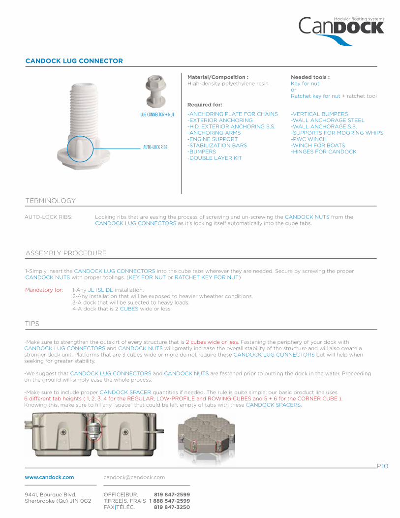
CANDOCK LUG CONNECTOR
Material/Composition :High-density polyethylene resin
TERMINOLOGY
ASSEMBLY PROCEDURE
1-Simply insert the CANDOCK LUG CONNECTORS into the cube tabs wherever they are needed. Secure by screwing the proper CANDOCK NUTS with proper toolings. (KEY FOR NUT or RATCHET KEY FOR NUT)
Mandatory for: 1-Any JETSLIDE installation. 2-Any installation that will be exposed to heavier wheather conditions. 3-A dock that will be sujected to heavy loads. 4-A dock that is 2 CUBES wide or less
TIPS
AUTO-LOCK RIBS: Locking ribs that are easing the process of screwing and un-screwing the CANDOCK NUTS from the CANDOCK LUG CONNECTORS as it’s locking itself automatically into the cube tabs.
-Make sure to strengthen the outskirt of every structure that is 2 cubes wide or less. Fastening the periphery of your dock with CANDOCK LUG CONNECTORS and CANDOCK NUTS will greatly increase the overall stability of the structure and will also create a stronger dock unit. Platforms that are 3 cubes wide or more do not require these CANDOCK LUG CONNECTORS but will help when seeking for greater stability.
-We suggest that CANDOCK LUG CONNECTORS and CANDOCK NUTS are fastened prior to putting the dock in the water. Proceeding on the ground will simply ease the whole process.
-Make sure to include proper CANDOCK SPACER quantities if needed. The rule is quite simple; our basic product line uses 6 different tab heights ( 1, 2, 3, 4 for the REGULAR, LOW-PROFILE and ROWING CUBES and 5 + 6 for the CORNER CUBE ). Knowing this, make sure to fill any “space” that could be left empty of tabs with these CANDOCK SPACERS.
-VERTICAL BUMPERS-WALL ANCHORAGE STEEL-WALL ANCHORAGE S.S.-SUPPORTS FOR MOORING WHIPS-PWC WINCH-WINCH FOR BOATS-HINGES FOR CANDOCK
-ANCHORING PLATE FOR CHAINS-EXTERIOR ANCHORING-H.D. EXTERIOR ANCHORING S.S.-ANCHORING ARMS-ENGINE SUPPORT-STABILIZATION BARS-BUMPERS-DOUBLE LAYER KIT
LUG CONNECTOR + NUT
Needed tools :Key for nutorRatchet key for nut + ratchet tool
Required for:
AUTO-LOCK RIBS

Modular floating systems
www.candock.com [email protected]
9441, Bourque Blvd.Sherbrooke (Qc) J1N 0G2
OFFICE|BUR. T.FREE|S. FRAIS FAX|TÉLÉC.
819 847-25991 888 547-2599
819 847-3250
P.11
CANDOCK NUT
Material/Composition :High-density polyethylene resin
ASSEMBLY PROCEDURE
***See LUG CONNCTOR assembly procedure.
NUT + LUG CONNECTOR
CANDOCK SPACER
Material/Composition :High-density polyethylene resin
Application:
ASSEMBLY PROCEDURE
-VERTICAL BUMPERS-WALL ANCHORAGE STEEL-WALL ANCHORAGE S.S.-SUPPORTS FOR MOORING WHIPS-PWC WINCH
-JETSLIDE LUG CONNECTOR-ANCHORING PLATE FOR CHAINS-EXTERIOR ANCHORING-H.D. EXTERIOR ANCHORING S.S.-CHAIN ADJSUTER-ANCHORING ARMS-ENGINE SUPPORT-STABILIZATION BARS-BUMPERS-DOUBLE LAYER KIT-POST TYPE HANDRAIL-CANDOCK HANDRAIL POST-WINCH FOR BOATS-HINGES FOR CANDOCK-CANDOCK LADDER
-If using a CANDOCK LUG CONNECTOR, align auto-lock treads of the CANDOCK LUG CONNECTOR in the 4 notches found on the spacers.
-Make sure to include proper CANDOCK SPACERS quantities if needed. The rule is quite simple; our basic product line uses 6 different tab heights ( 1, 2, 3, 4 for the REGULAR, LOW-PROFILE and ROWING CUBES and 5 + 6 for the CORNER CUBE ). Knowing this, make sure to fill any “space” that could be left empty of tabs with these CANDOCK SPACERS.
Needed tools :-Key for nutor-Ratchet key for nut + ratchet tool
Required for :CANDOCK LUG CONNECTOR
***Treads are tight between the CANDOCK NUT and the CANDOCK LUG CONNECTOR by design. Always use the provided tools to manipulate with ease.