Basic PowerPoint Presentation
25
Transcript of Basic PowerPoint Presentation

Talk Outline
Image ©
ST
FC
John D
aw
son
• DUNE APA factories
• Overview of key equipment
• DUNE build sequence
• DUNE APA assembly process
2

DUNE APA Factories - UK
Science and Technology Facilities Council, Daresbury Laboratory
3
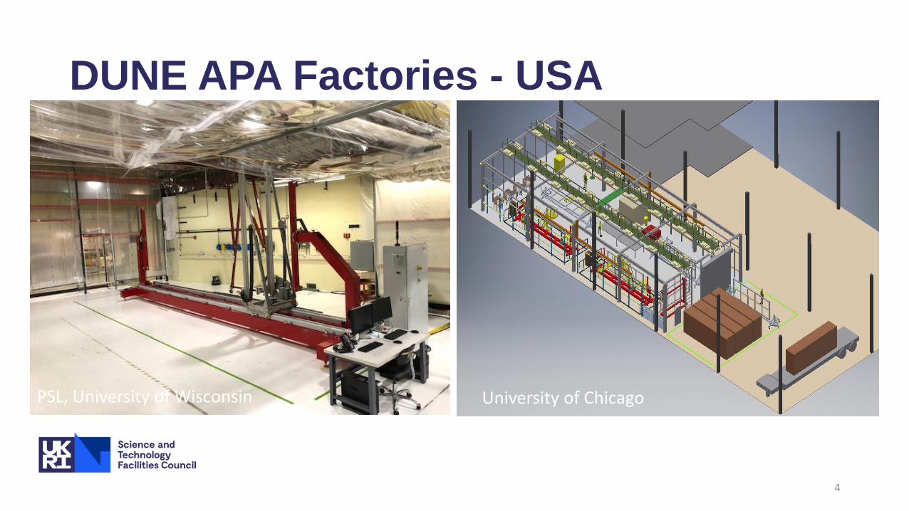
DUNE APA Factories - USA
4
University of ChicagoPSL, University of Wisconsin

APA winding machines
5
Winding machine 4 used for ProtoDUNE2 Winding machine 1 in DL factory

How we wind a diagonal plane
6

DUNE Process cart
7
Process carts are used to prepare frames for the winding machines and to move APAs around factories
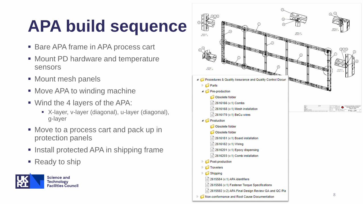
APA build sequence Bare APA frame in APA process cart
Mount PD hardware and temperature sensors
Mount mesh panels
Move APA to winding machine
Wind the 4 layers of the APA: X-layer, v-layer (diagonal), u-layer (diagonal),
g-layer
Move to a process cart and pack up in protection panels
Install protected APA in shipping frame
Ready to ship
8

Frame prep Install photon detector (PD) rails
and cables Electrical test of PD assemblies
(continuity and isolation against defined resistor values)
Install liquid argon temperature sensors and cabling Electrical test of resistance against
defined values
Install comb bases and combs
Ready for mesh panels
9
• 8760Doc003_Mesh_Panel_Installation.pdf• 8760Doc040_Mesh_Bracket_PD_Infrastructure_and_Temperature_Sensor_Installation.pdf• 8760Doc004_Comb_base_X_layer_wire_comb_installation.pdf

Mesh Panel install Inspected and QC checked mesh panels x 20 of 5 different types.
Insert mesh panel into mesh panel checking fixture for that panel
type and fit it’s cross-frame to pre-tension the mesh panels
Take mesh panel with fitted cross-frame and inserting into relevant section of the APA frame
Fix to mesh panel brackets using lock-washers
Repeat for remaining 19 mesh panels
Visual inspection against photograph of correct install and check there are no pockets in the mesh.
If pockets is found remove individual panel and re-process through inspection and QC steps.
Ready to install X-layer PCBs
10
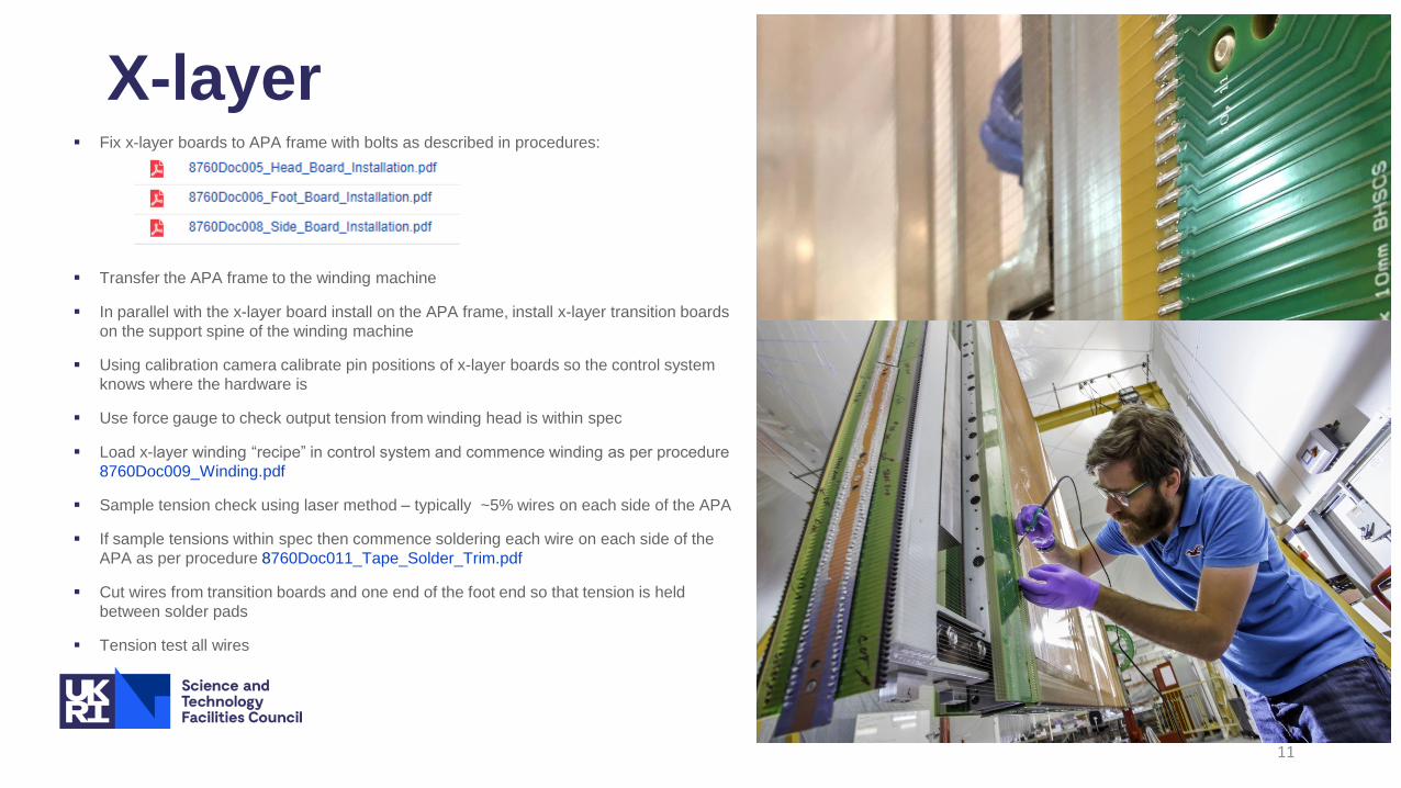
X-layer Fix x-layer boards to APA frame with bolts as described in procedures:
Transfer the APA frame to the winding machine
In parallel with the x-layer board install on the APA frame, install x-layer transition boards
on the support spine of the winding machine
Using calibration camera calibrate pin positions of x-layer boards so the control system
knows where the hardware is
Use force gauge to check output tension from winding head is within spec
Load x-layer winding “recipe” in control system and commence winding as per procedure
8760Doc009_Winding.pdf
Sample tension check using laser method – typically ~5% wires on each side of the APA
If sample tensions within spec then commence soldering each wire on each side of the
APA as per procedure 8760Doc011_Tape_Solder_Trim.pdf
Cut wires from transition boards and one end of the foot end so that tension is held
between solder pads
Tension test all wires
11

Laser tension method
Load laser head onto the winding machine
Isolate wires into “zone(s)” using a barrier on the combs. Zones are between the ribs of the APA.
For x- and g-layers only isolate in one zone to better control accuracy
For diagonal layers v- and u- layer 4 zones are isolated on each side of the APA which tests all the wires wound on these layers (because of how they wrap around the frame)
The reading is in Hz which is converted to N
The tension spec for the x- and g- layers is 6.5 N with a tolerance of +/-1N
The tension for the diagonal layers is dependent on the wire length as the spec is as follows:
Long wires have length ≥ 500mm Tension set point 6.5 N
Short wires have length < 500mm and ≥50mm Tension set point 5N
Very short wires have length <50mm n/a
12

Example of tensions
from g-layer of
ProtoDUNE2
APA#1 obtained
with laser method
13

DWA (DUNE Wire Analyser) tension method
Custom instrument measuring wire tension of eight wires
at a time using an electrical method
Measures the tension of a wire by stimulating at high voltage
its two neighbours in a wire plane
Accesses wires electrically by connecting to probe boards,
which themselves connect to the head boards in a similar way
to CR boards and G bias filter boards
Is supported in the winder by a rail spanning the APA width that
makes use of the CE tees mounting points
Outputs tension values directly in Sietch via software
In final stages of development
Production expected this fall
Possibility of testing electrical continuity of wires and
measuring wire capacitance
14

X-layer continued
If tensions within spec then trim excess wire back to solder pad on all wires
If any wire tensions are out of spec then replace these wire(s)
Electrical testing of all wires- continuity and isolation against defined spec at known RH% as per procedure: 8760Doc012_Electrical_Testing.pdf
If any values out of spec investigate issue and potentially replace wire
Proceed to v-layer
15

V-layer (diagonal layer) Fix v-layer boards to APA frame with bolts and epoxy using specified quantities of
epoxy applied in a defined pattern using a Nordson epoxy machine
Once boards are affixed in place wait 8 hours (epoxy cure time)
In parallel with affixing boards, install combs and v-layer transition boards
Using calibration camera calibrate pin positions of v-layer boards so the control system knows where the hardware is
Use force gauge to check output tension from winding head is within spec
Load v-layer winding “recipe” in control system and commence winding
Sample tension check using laser method – typically ~5% wires on each side of the APA
If sample tensions within spec then commence soldering each wire on each side of the APA
Cut wires from transition boards and one end of the foot end so that tension is held between solder pads
Tension test all wires
16

V-layer cont..
If tensions within spec then trim excess wire back to solder pad on all wires
If any wire tensions are out of spec then replace these wire(s)
Electrical testing of all wires- continuity and isolation against defined spec at known RH%
If any values out of spec investigate issue and potentially replace wire
Proceed to u-layer
17

U-layer (diagonal layer) Fix u-layer boards to APA frame with bolts and epoxy using
specified quantities of epoxy applied in a defined pattern using a Nordson epoxy machine
Once boards are affixed in place wait 8 hours (epoxy cure time)
In parallel with affixing boards, install combs and u-layer transition boards
Using calibration camera calibrate pin positions of u-layer boards so the control system knows where the hardware is
Use force gauge to check output tension from winding head is within spec
Load u-layer winding “recipe” in control system and commence winding
Sample tension check using laser method – typically ~5% wires on each side of the APA
If sample tensions within spec then commence soldering each wire on each side of the APA
Cut wires from transition boards and one end of the foot end so that tension is held between solder pads
Tension test all wires
18
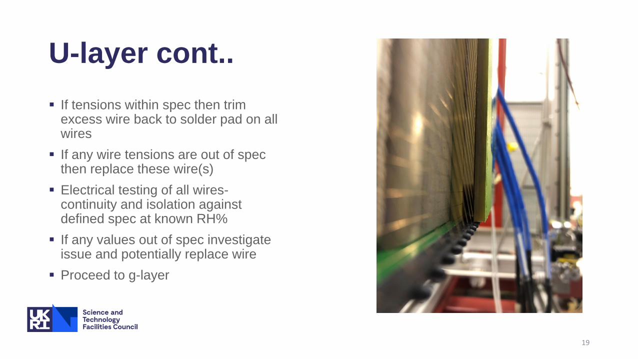
U-layer cont..
If tensions within spec then trim excess wire back to solder pad on all wires
If any wire tensions are out of spec then replace these wire(s)
Electrical testing of all wires-continuity and isolation against defined spec at known RH%
If any values out of spec investigate issue and potentially replace wire
Proceed to g-layer
19

G-layer Fix g-layer boards to APA frame with bolts and epoxy using specified
quantities of epoxy applied in a defined pattern using a Nordson epoxy machine
In parallel with the x-layer board install on the APA frame, install g-layer transition boards on the winding machine
Using calibration camera calibrate pin positions of g-layer boards so the control system knows where the hardware is
Use force gauge to check output tension from winding head is within spec
Load g-layer winding “recipe” in control system and commence winding
Sample tension check using laser method – typically ~5% wires on each side of the APA
If sample tensions within spec then commence soldering each wire on each side of the APA
Cut wires from transition boards and one end of the foot end so that tension is held between solder pads
Tension test all wires
20

G-layer cont..
If tensions within spec then trim excess wire back to solder pad on all wires
If any wire tensions are out of spec then replace these wire(s)
Electrical testing of all wires-continuity and isolation against defined spec at known RH%
If any values out of spec investigate issue and potentially replace wire
All planes wound
21

Cover boards & comb caps Fix cover boards to APA frame with bolts and epoxy using
specified quantities of epoxy applied in a defined pattern using a Nordson epoxy machine
Install comb caps onto combs
Apply epoxy to side board screw fixings
22

Protection panels
Move built APA to a process cart
Fit protection panels The panels comprise aluminium u-
section edge protection and foam composite side panels covering the faces of the APA
23

Prep for shipping
APA fitted in shipping frame/box
Conduit insertion
Seal shipping frame
APA ready to ship
24

Thank you
Facebook: Science and
Technology Facilities Council
Twitter:@STFC_matters YouTube: Science and
Technology Facilities Council