Bale Pro 4065-5 Owner’s Manual - Home | Highline … · · 2015-12-10Bale Pro 4065-5 Owner’s...
65
Highline Mfg. Inc. June 2004 Bale Pro 4065-5 Bale Pro 4065-5 Bale Pro 4065-5 Bale Pro 4065-5 Bale Pro 4065-5 Owner Owner Owner Owner Owner’s Manual ’s Manual ’s Manual ’s Manual ’s Manual E8535_B
Transcript of Bale Pro 4065-5 Owner’s Manual - Home | Highline … · · 2015-12-10Bale Pro 4065-5 Owner’s...

Highline Mfg. Inc. June 2004
Bale Pro 4065-5Bale Pro 4065-5Bale Pro 4065-5Bale Pro 4065-5Bale Pro 4065-5OwnerOwnerOwnerOwnerOwner’s Manual’s Manual’s Manual’s Manual’s Manual
E8535_B

Highline Mfg.Inc. BP4065-5
Page 2
Table of ContentsWarranty ........................................................................................................... 5President’s Message ........................................................................................ 6Safety Precautions ............................................................................................ 71.0 Operating Instructions ................................................................................. 8
1.1 General Operating Instructions ................................................................................ 82.0 Maintenance Instructions........................................................................... 103.0 Safety Messages ...................................................................................... 12
3.1 Decal Location (Part No. 49666) ......................................................... 163.2 Safety Lock Locations ......................................................................... 22
4.0 Parts Information ....................................................................................... 244.1 Tub and Frame Assembly (Part No. 49932)........................................................... 244.2A Feed Roller Assembly (Part No. 49914) .............................................................. 25
4.2A.1 Feed Roller Drive (Part No. 49917) ............................................................. 264.2B Feed Roller Assembly (Part No. 49674) .............................................................. 27
4.2.2 Hydraulic Motor (Part No. 33377) .................................................................. 284.3 Driveline Guard Assembly (Part No. 49944) .......................................................... 294.4 Flail Drum Installation (Part No. 49933) ................................................................. 30
4.4.1 Flail Drum Assembly (Part No. 49908) ........................................................... 314.5 Flail Guard Rod Assembly (Part No. 49934) .......................................................... 324.6 Bale Defelctor Assembly (Part No. 49935) ............................................................ 334.7 Bottom Discharge Door Assembly (Part No. 49936) ............................................. 344.8 Hydraulic Assembly (Part No. 49938) .................................................................... 354.9A Loading Forks and Frame Assembly (Part No. 49937) ........................................ 36
4.9.1 Cylinder Assembly (Part No. 33800) .............................................................. 364.9B Loading Forks and Frame Assembly (Part No. 49937)........................................ 384.10 Upper Discharge Door Assembly (Part No. 49942) ............................................. 404.11A Tire, Hitch and Jack Assembly (Part No. 49945) ............................................... 424.11B Tire, Hitch and Jack Assembly (Part No. 49945) ............................................... 43
4.11.1 Hub Assembly (Part No. 45224) ................................................................... 444.11A.2 Tire Assembly (Part No. 49089) ................................................................. 444.11B.2 Tire Assembly (Part No. 49895) ................................................................. 444.11.3 Jack Assembly (Part No. 33835) .................................................................. 454.11.4 Spindle Assembly (Part No. 49571) .............................................................. 45

Highline Mfg.Inc.
Page 3
BP4065-55.0 Options ..................................................................................................... 46
5.1 Standard PTO Option (Part No. BPO4PTO-5) ...................................................... 465.1.1 Standard PTO (Part No. 33836) .................................................................... 46
5.2 CV PTO Option (Part No. BPO4CVPTO-5 (89062)) ............................................. 475.2.1 CV PTO (Part No. 45230) .............................................................................. 48
5.4 Hitch Clevis Option (Part No. BPOHC-4 (89004)) .................................................. 505.5 Flow Control Option (Part No. BPOFC-4 (89005)) ................................................ 515.6 Safety Chain Option (Part No. BPOSC-4 (89006)) ................................................ 51
STANDARD TIRE MOUNTING ........................................................................................... 526.0 Parts Index ................................................................................................ 547.0 Specifications ............................................................................................ 57Dealer Information .......................................................................................... 58Identification Numbers..................................................................................... 58Dealer Checklist .............................................................................................. 59

Highline Mfg.Inc. BP4065-5
Page 4
This page intentionally left blank.
Highline Mfg.Inc.
Page 5
BP4065-5
WarrantyHighline New Agricultural Equipment Limited Warranty
Effective January 1, 2004 One (1) Year / 12 Months Parts and Labour
Highline Mfg. Inc (hereinafter "Highline") warrants this new Agricultural product of Highline's manufacturer to be free from defects in material and workmanship, under normal use and service for one (1) full year after initial purchase/retail sale. Highline will warrant its product for one (1) year parts and labour, if performed by a qualified Dealer. This Limited Warranty shall apply only to complete machines of Highline's manufacture, parts are covered by a separate Limited Warranty. EQUIPMENT AND ACCESSORIES NOT OF HIGHLINE'S MANUFACTURE ARE WARRANTED ONLY TO THE EXTENT OF THE ORIGINAL MANUFACTURER'S WARRANTY AND SUBJECT TO THEIR ALLOWANCE TO HIGHLINE ONLY IF FOUND DEFECTIVE BY SUCH MANUFACTURER. During the Limited Warranty period specified above, any defect in material or workmanship in any warranted item of Highline Agricultural Equipment not excluded below shall be repaired or replaced at Highline's option without charge by any authorized independent Highline Dealer. An authorized Dealer must make the warranty repair or replacement. Labour in accordance with Highline's labour reimbursement policy. Highline reserves the right to supply remanufactured replacement parts as it deems appropriate. RETAIL PURCHASER RESPONSIBILITY: This Limited Warranty requires proper maintenance and periodic inspections of the Agricultural Equipment as indicated in the Operator's Manual furnished with each new Agricultural Equipment. The cost of routine or required maintenance and services is the responsibility of the retail purchaser. The retail purchaser is required to keep documented evidence that these services were performed. This Highline New Agricultural Equipment Limited Warranty may be subject to cancellation if the above requirements are not performed EXCLUSIONS AND LIMITATIONS The warranties contained herein shall NOT APPLY TO:
(1) Any defect which was caused (in Highline's sole judgement) by other than normal use and service of the Agricultural Equipment, or by any of the following: (i) accident (ii) misuse or negligence (iii) overloading (iv) lack of reasonable and proper maintenance (v) improper repair or installation (vi) unsuitable storage (vii) non-Highline approved alteration or modification (viii) natural calamities (ix) vandalism (x) parts or accessories installed on Agricultural Equipment which were not manufactured or installed by Highline authorized Dealers (xi) the elements (xii) collision or other accident.
(2) Any Agricultural Equipment whose identification numbers or marks have been altered or removed. (3) Any Agricultural Equipment which any of the required or recommended periodic inspection or services have
been performed using parts not manufactured or supplied by Highline or meeting Highline Specifications including, but without limitation, lubricants (oil, grease), belt lacings, and hydraulic fluids.
(4) Equipment used for rental, custom work, industrial and construction or if equipment is used for any other purpose than the intended agricultural application.
(5) Any Agricultural Equipment used in demonstrations not performed by a Highline Dealer. Warranty will be at the discretion of Highline for all other demonstration warranty.
(6) New Agricultural Equipment delivered to the retail purchaser in which the warranty registration has not been completed and returned to Highline within ten (10) days from the date of purchase.
(7) Any defect that was caused (in Highline's sole judgement) by operation of the Agricultural Equipment not abiding by standard operating procedures outlined in the Operator's Manual.
(8) Tire Limited Warranties and support are the responsibility of the respective product's manufacturer. (9) Transportation costs, if any, of transporting to the Highline Dealer. (10) In no event shall Highline's liability exceed the purchase price of the product. (11) Highline shall not be liable to any person under any circumstances for any incidental or consequential damages
(including but not limited to, loss of profits, out of service time and damage to equipment which this equipment may be attached) occurring for any reason at any time.
(12) Diagnostic and overtime labour premiums are not covered under this Limited Warranty Policy. (13) Depreciation damage caused by normal wear, lack of reasonable and proper maintenance, failure to follow
operating instructions, misuse, and/or lack of proper protection during storage. (14) Accessory systems and electronics not of Highline's manufacture are warranted only to the extent of such
manufacturer's respective Limited Warranty if any. (15) Wear items which are listed by product group below:
COMMON WEAR ITEMS: roller chain, sprockets, clutches, shear bolts, clutch components, chains, gearbox housings bolts/torqued parts, flails, feed roller belting, coupler chain, DRV couplers, bogie wheels, apron tines and hoses. PARTS WARRANTY Parts replaced in the warranty period will receive the balance of the one year New Agricultural Equipment Limited Warranty. Replacement parts after the original machine warranty are warranted to be free from defects of material for ninety (90) days or the part will be repaired or replaced, without labour coverage for removal and reinstallation. EXCLUSION OF WARRANTIES. UNLESS OTHERWISE REQUIRED BY LAW, AND EXCEPT FOR THE WARRANTIES EXPRESSLY AND SPECIFICALLY MADE HEREIN, HIGHLINE MAKES NO OTHER WARRANTIES, AND ANY POSSIBLE LIABILITY OF HIGHLINE HEREIN UNDER IS IN LIEU OF ALL OTHER WARRANTIES, EXPRESS, IMPLIED, OR STATUTORY, INCLUDING, BUT NOT LIMITED TO, ANY WARRANTIES OF MERCHANT ABILITY OR FITNESS FOR A PARTICULAR PURPOSE. HIGHLINE RESERVES THE RIGHT TO MODIFY, ALTER AND IMPROVE ANY PRODUCT WITHOUT INCURRING ANY OBLIGATION TO REPLACE ANY PRODUCT PREVIOUSLY SOLD WITH SUCH MODIFICATION. NO PERSON IS AUTHORIZED TO GIVE ANY OTHER WARRANTY, OR TO ASSUME ANY ADDITIONAL OBLIGATION ON HIGHLINE'S BEHALF.

Highline Mfg.Inc. BP4065-5
Page 6
President’s Message
Congratulations on your purchase of the Bale Pro 4065! Bale Pro, a proven name in livestockfeed handling equipment, is manufactured by Highline Mfg. Inc. Highline Mfg. Inc. is a company withover 25 years experience in the farm implement industry.
This operator’s manual has been prepared to provide information necessary for safe and efficientoperation of your Bale Pro 4065. In this manual you will find safety procedures, maintenance routinesand detailed parts diagrams. This bale processor model was designed for controlled, aggressiveprocessing with less bunching. A little time and effort spent following the recommended maintenanceprocedures will increase the performance and durability of your bale processor.
In order to maintain our high standards, improvements are made from time to time. Highline Mfg. Inc.reserves the right to make such changes and improvements when practical to do so without incurringany obligation to make those changes and improvements on previously sold machines.
Should the need arise, this manual will assist you in acquiring replacement parts. If your dealer doesnot have the parts you require in stock, they will be happy to order them for you. Also, if you find thatyou require information not covered in this manual, feel free to consult you local dealer or HighlineMfg. Inc.
Highline Mfg. Inc. thanks and congratulates you for choosing the Bale Pro 4065 as the livestock feedhandling equipment for your needs.
Chuck LePage, PresidentHighline Mfg. Inc.
PO Box 307, Vonda, Saskatchewan, S0K 4N0Phone 1-800-665-2010 Fax (306) 258-2010Internet Address: http://www.highlinemfg.com
Highline Mfg.Inc.
Page 7
BP4065-5
Safety Precautions
WORK SAFELY – FOLLOW THESE INSTRUCTIONS
CAREFUL OPERATION IS THE BEST INSURANCE AGAINST AN ACCIDENT!
123456789012345678901234567890121234567890123456789012345678901212345678901234567890123456789123456789012345678901234567890121234567890123456789012345678901212345678901234567890123456789123456789012345678901234567890121234567890123456789012345678901212345678901234567890123456789
123456789012345678901234567890121234567890123456789012345678901212345678901234567890123456789123456789012345678901234567890121234567890123456789012345678901212345678901234567890123456789
Before operating the Bale Pro 4065, be sure to review all of the instructions and familiarizeyourself with its features.
• Keep children and adults away from discharge area while processing.• Know the controls and what they do.• Check the machine to ensure nothing restricts moving or rotating parts.• Ensure PTO is disengaged before starting tractor.• Never leave tractor while PTO is engaged.• Lower forks to ground after operation.• Never attempt to manually remove debris while the PTO is activated.• Do not transport Bale Pro on highway with PTO extension shaft on machine or with
bales in tub or on the forks.• Disconnect PTO before unplugging or adjusting processor.• Always keep safety shields in place.• Relieve pressure in hydraulic lines before disconnecting lines or performing other
work on the hydraulic system.• Never allow anyone to stand behind the processor while loading bales.• Ensure the discharge door is raised completely with transport lock installed to lock it to
the tub when transporting machine.

Highline Mfg.Inc. BP4065-5
Page 8
1.0 Operating Instructions
Successful operation of the Bale Pro 4065 is dependent upon the consistency of the bale, the positionof the flail guard rods, the speed of the feed roller and also upon the operator. The following stepsensure proper and efficient operation. Please read them all carefully before operating your newBP4065.
1. Ensure that the drawbar on the tractor is extended so that the pin is 17” from the groove on thePTO on the tractor for the standard 1-3/8” diameter, 1000 rpm yoke.
2. It is recommended that the hitch tongue be placed so that the Bale Pro 4065 frame is level orslightly downward toward the tractor. This will ensure that the bale forks are low enough to loada bale. Ensure adequate clearance to the PTO shaft.
3. Ensure that the machine stays properly greased at all recommended locations (See MaintenanceInstructions).
4. The top discharge deflector is manually controlled. The transport lock is located in the middle ofthe door on the discharge side. Disengage the lock and lower the door until the chains carry theweight. Use the handle on the front side of the door to fully raise the door into operating position.The operating lock is located on the top side of the door. Engage the lock into the tab on the topdeflector and engage the lock pin to ensure the operating lock does not disengage during opera-tion.
5. To adjust the bottom discharge deflector, stand on the left side of the machine, pull the bottomdeflector toward the front of the machine, raise or lower the door as required and then releasethe door to allow the spring to engage the door into one the desired retaining holes.
6. The adjustment of the flail guard rods is done with the handle on the front of the machine. Pullthe handle towards yourself and raise or lower the handle. Raising the handle will make the BalePro more aggressive while lowering the handle will make it less aggressive. There are fourdifferent settings for the flail guard rods as shown on the decal by the handle. If the processor isoperated too aggressively, the flails will slap back on the flail drum. Continued ‘backslap’ cancause damage and unnecessary wear to the flail drum, flails, and flail bushings. There-fore, avoid excessive and prolonged ‘backslap’ whenever possible by adjusting the flail guardrods to a slightly less aggressive setting and reducing the bale rotation speed while processing.
7. The feed roller speed should be set to a maximum of 40 rpm. It is HIGHLY RECOMMENDED forfirst time users to run the feed roller even slower. Running the feed roller too fast will cause thefeed roller to dig a hole in the bale to the point where the bale cannot be processed.Adjustment can be done by adjusting the flow control on the tractor (if it is equipped with a flowcontrol). If you do not have a flow control on your tractor, a flow control kit can be purchasedfrom your Highline dealer.
Pin to Groove
1.1 General Operating Instructions

Highline Mfg.Inc.
Page 9
BP4065-58. Before loading the bale, engage the PTO to ensure that the flail drum is operating properly. Start
feed rollers using the hydraulic controls and check to ensure the feed roller turns in both direc-tions.
9. To load bales, lower the forks completely and back up to the bale slowly until the forks arecompletely under the bale. Raise the forks until the bale falls into the processor. The bale willnot lift if it is pressing up against another bale. Another bale may be loaded onto the forks while abale is in the processor. If a bale is loaded onto the forks while one is being shredded, raise theforks as high as possible, making sure the bale on the forks does not interfere with the balealready in the tub. Raising the forks will reduce the pressure on the hydraulic lift assembly.
10. Orientation of the bale during loading causes the hay/straw to discharge from the processordifferently. If the bale is shredded in the same direction in which it was baled, the hay/strawtends to come off in layers. If the bale is shredded in the opposite direction, feeding may beuneven.
11. Do not dislodge frozen bales with forks. Damage to the lift mechanism may result.
12. When ready, engage the tractor PTO at an idle. Increase the PTO speed until it reaches 1000rpm. Make sure that before the PTO is engaged, the forks are not interfering with the bale in thetub.
13. To process bales, rotate the bale using the feed roller. It is recommended to start processing thebales in a counter - clockwise rotation (as see from the front of the machine). If the bale stopsrotating, reverse the direction of the feed roller for no more than 1 second only and then continueprocessing in the counter - clockwise rotation. Once the bale has reached approximately half ofits original diameter, the bale can be processed in the clockwise direction. If the bale stopsrotating, reverse the direction of the feed roller for 1 or 2 seconds only.
Note: Since the feed roller is designed to be aggressive for positive bale rotation, it isNOT recommended to rotate the feed roller in the reverse direction for more than a onesecond when the bale is stalled.
13. Before stopping the PTO, idle down (tractors with PTO brakes) to reduce flail ‘backslap’.
WARRANTY WILL BE VOID IF ANY COMPONENT OF THIS MACHINE IS ALTERED ORMODIFIED IN ANY WAY WITHOUT WRITTEN PERMISSION FROM HIGHLINE MFG. INC.
Top DischargeTransport Lock
Bottom DeflectorAdjustment
Flail Guard RodAdjustment
Highline Mfg.Inc. BP4065-5
Page 10
2.0 Maintenance Instructions
Please follow these maintenance procedures to ensure years of trouble free opera-tion of your Bale Pro 4065.
Twine must be removed from the flail drum at least every 25 bales. Premature bearingfailure can occur if twine is allowed to build up on the flail drum.
Flail bolts must be tightened after the first ten bales and rechecked after approximately 200bales (160 ft lbs min., 240 ft lb max.).
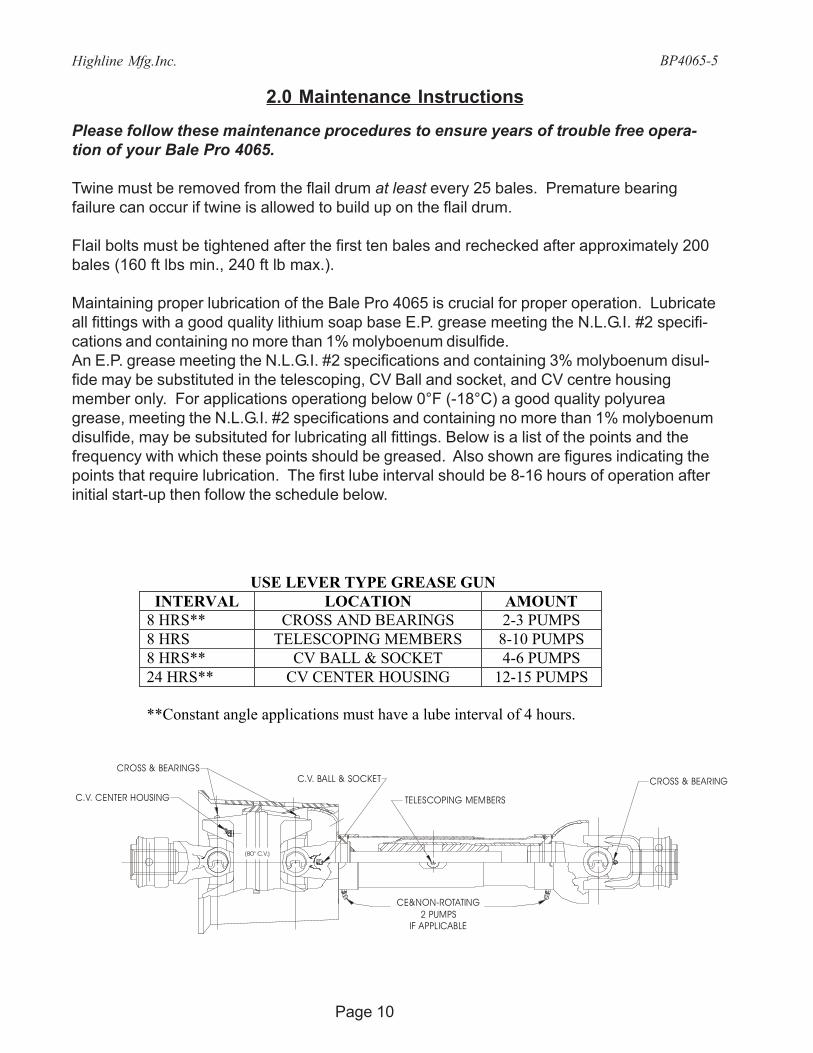
Maintaining proper lubrication of the Bale Pro 4065 is crucial for proper operation. Lubricateall fittings with a good quality lithium soap base E.P. grease meeting the N.L.G.I. #2 specifi-cations and containing no more than 1% molyboenum disulfide.An E.P. grease meeting the N.L.G.I. #2 specifications and containing 3% molyboenum disul-fide may be substituted in the telescoping, CV Ball and socket, and CV centre housingmember only. For applications operationg below 0°F (-18°C) a good quality polyureagrease, meeting the N.L.G.I. #2 specifications and containing no more than 1% molyboenumdisulfide, may be subsituted for lubricating all fittings. Below is a list of the points and thefrequency with which these points should be greased. Also shown are figures indicating thepoints that require lubrication. The first lube interval should be 8-16 hours of operation afterinitial start-up then follow the schedule below.
CROSS & BEARINGS
C.V. CENTER HOUSING
C.V. BALL & SOCKET
(80° C.V.)
CE&NON-ROTATING2 PUMPS
IF APPLICABLE
TELESCOPING MEMBERS
CROSS & BEARING
USE LEVER TYPE GREASE GUN INTERVAL LOCATION AMOUNT
8 HRS** CROSS AND BEARINGS 2-3 PUMPS 8 HRS TELESCOPING MEMBERS 8-10 PUMPS 8 HRS** CV BALL & SOCKET 4-6 PUMPS 24 HRS** CV CENTER HOUSING 12-15 PUMPS **Constant angle applications must have a lube interval of 4 hours.

Highline Mfg.Inc.
Page 11
BP4065-5
CAUTION: REPLACEMENT PARTS ARE NOT LUBRICATED
Replacement parts must be lubricated at time of assembly. Use amount listed above perlocation then follow lube recommendations outlined above for lubing intervals.
1. Flail Drum Bearings (Front and Rear): Every 8 hrs.2. Wheel Hub Bearings (Left and Right): Every 16 hrs.
*Use low temperature grease when the temperature reaches below 0º Celsius (32ºFahrenheit).

Highline Mfg.Inc. BP4065-5
Page 12
Understand Signal Words.A signal word “Danger”, “Warning”, or “Caution” is used with the safety alert symbol.
Safety signs with signal word “Danger”, “Warning” or “Caution” are located near specifichazards.
Danger – Imminent hazards which, if not avoided, will result in serious personal injury ordeath.
Warning – Potential hazards or unsafe practices which, if not avoided, could result in seri-ous personal injury or death.
Caution – Potential hazards or unsafe practices which, if not avoided, could result in minorpersonal injury or product or property damage.
3.0 Safety Messages
General safety messages appear in this Safety Messages section.Specific safety messages are located in appropriate sections of themanual where a potential hazard may occur if the instructions orprocedures are not followed.
Understand Safety Alert SymbolThis is the safety alert symbol. This symbol placed on your machineor in the manual is used to alert you to the potential for bodily injury ordeath.
Read, Understand, and Follow Safety InstructionsRead, understand and follow all instructions and safety messagesincluded in this manual and on decals attached to the machine.These instructions and safety messages contain important informa-tion.
Allow only responsible, properly instructed individuals to operateand service the machine.
Failure to follow the instructions and safety messages in this manualand on the decals attached to the machine could result in seriousinjury or death.
Keep all safety and instruction decals in good condition. Replaceany missing or damaged decals.

Highline Mfg.Inc.
Page 13
BP4065-5
Keep Machine in Good ConditionBe sure the machine is in good operating condition and that all safety devices are installedand functioning properly.
Visually inspect the machine daily before starting the machine.
Make no modifications to your equipment unless specifically recommended or requested byHighline Mfg Inc.
Keep Spectators Away From MachineKeep all spectators and other workers away from the machine and work area while in op-eration.
Avoid Moving PartsContact with moving parts can cause death or serious injury.
• Keep away from power-driven parts such as the feed roller, flail drum and dump.• Wear close-fitting clothing and confine long hair. Avoid wearing jewelry, such as
rings, wrist watches, necklaces, or bracelets.• Keep all shields and doors closed during operation.
Avoid High Pressure LeaksPressurized fluid can penetrate body tissue and result in serious injury or death. Leaks canbe invisible. Relieve pressure before working on system. When searching for a leak, use anobject like cardboard – not your hand. Fluid injected under the skin must be removed imme-diately by a surgeon familiar with this type of injury.
Avoid Tire ExplosionTire explosion can result if the following procedures are not followed:
• Maintain correct tire pressure. Do not inflated tire above recommended pressure.• Low tire pressure can cause internal tire damage. Inflate to recommended pres-
sure.• Replace any tire with cuts or bubbles. Replace any damaged rims.• Do not weld or heat wheel assembly. Heating will increase tire pressure.
Highline Mfg.Inc. BP4065-5
Page 14
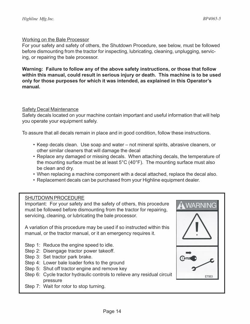
SHUTDOWN PROCEDUREImportant: For your safety and the safety of others, this proceduremust be followed before dismounting from the tractor for repairing,servicing, cleaning, or lubricating the bale processor.
A variation of this procedure may be used if so instructed within thismanual, or the tractor manual, or it an emergency requires it.
Step 1: Reduce the engine speed to idle.Step 2: Disengage tractor power takeoff.Step 3: Set tractor park brake.Step 4: Lower bale loader forks to the groundStep 5: Shut off tractor engine and remove keyStep 6: Cycle tractor hydraulic controls to relieve any residual circuit
pressureStep 7: Wait for rotor to stop turning.
Working on the Bale ProcessorFor your safety and safety of others, the Shutdown Procedure, see below, must be followedbefore dismounting from the tractor for inspecting, lubricating, cleaning, unplugging, servic-ing, or repairing the bale processor.
Warning: Failure to follow any of the above safety instructions, or those that followwithin this manual, could result in serious injury or death. This machine is to be usedonly for those purposes for which it was intended, as explained in this Operator’smanual.
Safety Decal MaintenanceSafety decals located on your machine contain important and useful information that will helpyou operate your equipment safely.
To assure that all decals remain in place and in good condition, follow these instructions.
• Keep decals clean. Use soap and water – not mineral spirits, abrasive cleaners, orother similar cleaners that will damage the decal
• Replace any damaged or missing decals. When attaching decals, the temperature ofthe mounting surface must be at least 5°C (40°F). The mounting surface must alsobe clean and dry.
• When replacing a machine component with a decal attached, replace the decal also.• Replacement decals can be purchased from your Highline equipment dealer.

Highline Mfg.Inc.
Page 15
BP4065-5
30285_C
Stay Clear Of Rotating DrivelineEntanglement in rotating driveline can cause death or serious injury.
• Keep driveline shields in place at all times. Ensure shieldsturn and telescope freely.
• Wear close-fitting clothing and confine long hair.• Stop engine and ensure the PTO driveline is stopped before
working on driveline
Avoid Discharge AreaStay away from discharge side of Bale Processor when PTO isengaged. Injury of blindness is possible from material leavingdischarge area.
DANGER: Contact with moving parts can result in death or seriousinjury. Always disengage power takeoff, set park brake,lower loader forks to the ground, shut off tractor engine,remove key, and wait for PTO to stop turning beforeunplugging by hand.
WARNING: Install and secure cylinder lock before servicing.
WARNING
E5868_B
Highline Mfg.Inc. BP4065-5
Page 16
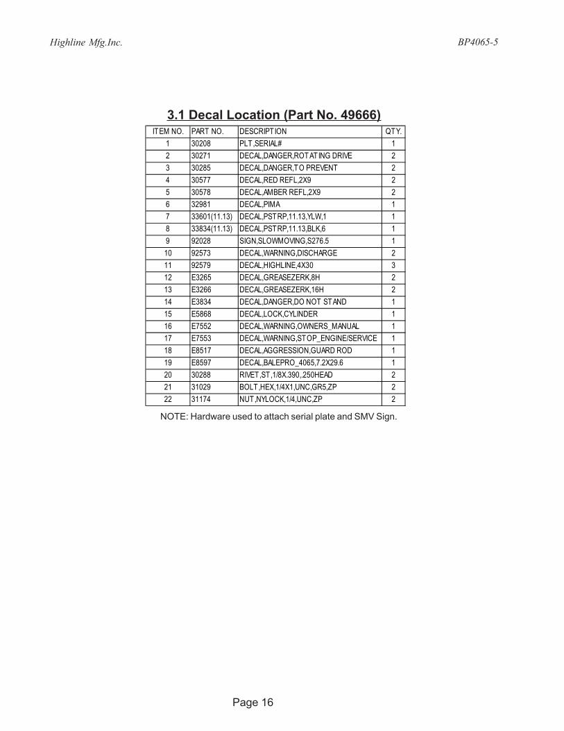
3.1 Decal Location (Part No. 49666)
NOTE: Hardware used to attach serial plate and SMV Sign.
ITEM NO. PART NO. DESCRIPTION QTY.1 30208 PLT,SERIAL# 12 30271 DECAL,DANGER,ROTATING DRIVE 23 30285 DECAL,DANGER,TO PREVENT 24 30577 DECAL,RED REFL,2X9 25 30578 DECAL,AMBER REFL,2X9 26 32981 DECAL,PIMA 17 33601(11.13) DECAL,PSTRP,11.13,YLW,1 18 33834(11.13) DECAL,PSTRP,11.13,BLK,6 19 92028 SIGN,SLOWMOVING,S276.5 110 92573 DECAL,WARNING,DISCHARGE 211 92579 DECAL,HIGHLINE,4X30 312 E3265 DECAL,GREASEZERK,8H 213 E3266 DECAL,GREASEZERK,16H 214 E3834 DECAL,DANGER,DO NOT STAND 115 E5868 DECAL,LOCK,CYLINDER 116 E7552 DECAL,WARNING,OWNERS_MANUAL 117 E7553 DECAL,WARNING,STOP_ENGINE/SERVICE 118 E8517 DECAL,AGGRESSION,GUARD ROD 119 E8597 DECAL,BALEPRO_4065,7.2X29.6 120 30288 RIVET,ST,1/8X.390,.250HEAD 221 31029 BOLT,HEX,1/4X1,UNC,GR5,ZP 222 31174 NUT,NYLOCK,1/4,UNC,ZP 2

Highline Mfg.Inc.
Page 17
BP4065-5
DANGER
30285_C
HIGHLINEMFG. INC.MADE IN CANADAFABRIQUÉ AU CANADA
P.O. BOX 307, VONDA, SK CANADA S0K 4N01
2
3
4
5
8
7
6
10
9
16
17
18
19
11
12
13
14
15
E7552_B
WARNING
WARNING
E7553_B
Highline Mfg.Inc. BP4065-5
Page 18
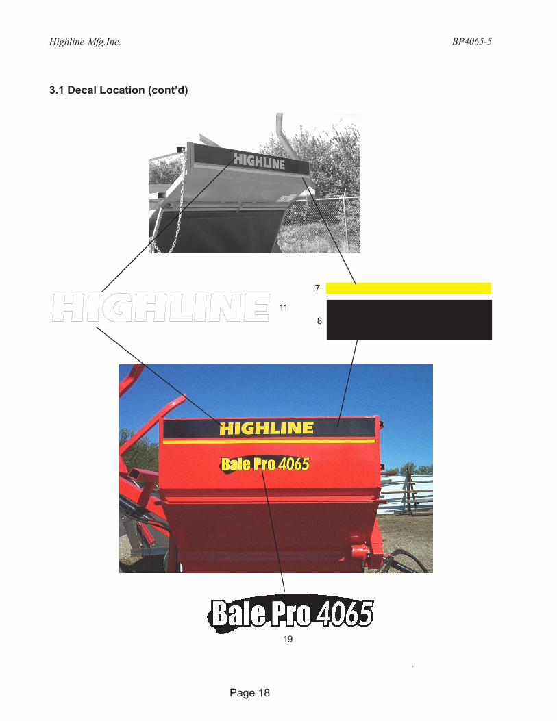
3.1 Decal Location (cont’d)
118
7
19

Highline Mfg.Inc.
Page 19
BP4065-5
3.1 Decal Location (cont’d)
DANGER
30285_C
HIGHLINEMFG. INC.MADE IN CANADAFABRIQUÉ AU CANADA
P.O. BOX 307, VONDA, SK CANADA S0K 4N01
23
5
6
16
17
14
E7552_B
WARNING
WARNING
E7553_B
18
12
11

Highline Mfg.Inc. BP4065-5
Page 20
3.1 Decal Location (cont’d)
10
915
30285_C
3
4

Highline Mfg.Inc.
Page 21
BP4065-5
3.1 Decal Location (cont’d)
12
13

Highline Mfg.Inc. BP4065-5
Page 22
3.2 Safety Lock Locations
1. Discharge Door - Transport Position
2. Discharge Door - Working Position
Safety / Transport Lock
Safety Lock with Retaining Pin
Retaining pin storage location
Highline Mfg.Inc.
Page 23
BP4065-5
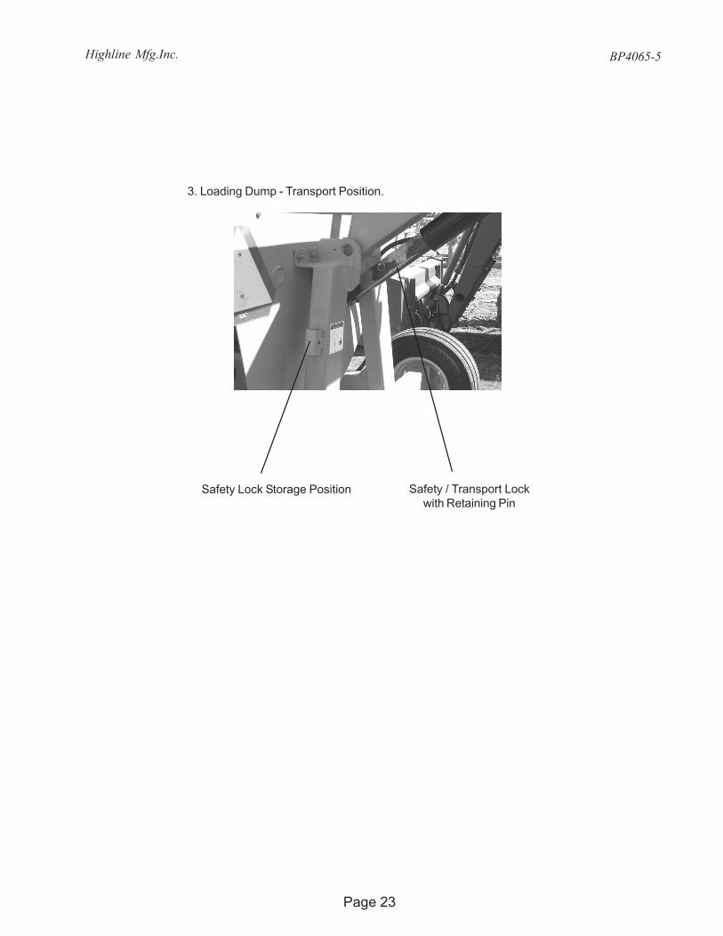
3. Loading Dump - Transport Position.
Safety Lock Storage Position Safety / Transport Lockwith Retaining Pin

Highline Mfg.Inc. BP4065-5
Page 24
4.0 Parts Information
4.1 Tub and Frame Assembly (Part No. 49932)ITEM NO. PART NO. DESCRIPTION QTY.
1 49669 WLDT,TUB,BP4065 12 49905 WLDT,FRAME,BP 13 49943 WLDT,PANEL,INNER 14 31945 BOLT,U,SQ,1/2-13X4X7-1/2 25 31016 BOLT,HEX,1/2X1-1/2,UNC,GR5,ZP 36 31017 BOLT,HEX,1/2X1-3/4,UNC,GR5,ZP 47 31173 NUT,NYLOCK,1/2,UNC,ZP 118 31236 WASHER,FLAT,1/2,ZP 12

Highline Mfg.Inc.
Page 25
BP4065-5
ITEM NO. PART NO. DESCRIPTION QTY.1 49913 WLDT, FEED_ROLL 12 49917 ASSY,DRIVE,FEEDROLLER 13 33655 BEARING,CARTRIDGE,FLANGE,1-3/4" 14 92094 DRV, BRG, FLANGE, 1-3/8" 15 31017 BOLT,HEX,1/2X1-3/4,UNC,GR5,ZP 46 31150 BOLT,HEX,1/2X2-1/4,UNC,GR5,ZP 47 31173 NUT,NYLOCK,1/2,UNC,ZP 128 31154 BOLT,CARR,1/2X1-1/4,UNC,GR5,ZP 4
4.2A Feed Roller Assembly (Part No. 49914)USE FOR MACHINES UP TO AND INCLUDING SERIAL NUMBER BP40650755

Highline Mfg.Inc. BP4065-5
Page 26
4.2A.1 Feed Roller Drive (Part No. 49917) USE FOR MACHINES UP TO AND INCLUDING SERIAL NUMBER BP40650755
ITEM NO. PART NO. DESCRIPTION QTY.1 49916 WLDT,MOUNT,BRG_TWINE_MOTOR 12 75437 DRV,SPROCKET,COUPLING,SPLINE 13 E6405 PIPE,SMLS,2-1/4x.240x1/4L 14 E7386 GUARD,FEEDROLLER_CHAIN 15 E7542 CHAIN,ROLLER,#80,15 LINKS 16 E8054 BLOCK,GUIDE,CHAIN 27 33377 HYD,MOTOR,22.8,3000PSI 18 33656 BEARING,INSRT,1-3/4 B,85mmOD 19 33658 DRV,SPRKT,#80,24,1-3/4-20SPL 110 33659 CHAIN,CONNECTOR_LINK,#80 111 33679 SPRING,EXT,31/64ODX5-1/4X.063 212 31012 BOLT,CARR,1/4X1,UNC,GR5,ZP 413 31016 BOLT,HEX,1/2X1-1/2,UNC,GR5,ZP 114 31173 NUT,NYLOCK,1/2,UNC,ZP 615 31164 NUT,HEX,1/4,UNC,GR5,ZP 416 31245 WASHER,LOCK,1/4,ZP 417 31244 WASHER,LOCK,1/2,ZP 118 32734 WASHER,FLAT,3-1/8ODX1/2 1

Highline Mfg.Inc.
Page 27
BP4065-5
4.2B Feed Roller Assembly (Part No. 49674)USE FOR MACHINES WITH SERIAL NUMBER BP40650756 AND HIGHER
ITEM NO. PART NO. DESCRIPTION QTY.1 49673 WLDT, FEED_ROLL 12 75437 DRV,SPROCKET,COUPLING,SPLINE 13 E8540 ANGLE,TURN,BALE 34 E8585 CHAIN,ROLLER,#80,22 LINKS 15 E8587 COVER,DRIVE,FROLL 16 E8588 PLATE,GUARD,FINGER 17 30294 SCREW,TEK,1/4X1 38 33377 HYD,MOTOR,22.8,3000PSI 19 33655 BEARING,CARTRIDGE,FLANGE,1-3/4" 110 33656 BEARING,INSRT,1-3/4 B,85mmOD 111 33658 DRV,SPRKT,#80,24,1-3/4-20SPL 112 33659 CHAIN,CONNECTOR_LINK,#80 113 92094 DRV, BRG, FLANGE, 1-3/8" 114 31016 BOLT,HEX,1/2X1-1/2,UNC,GR5,ZP 115 31017 BOLT,HEX,1/2X1-3/4,UNC,GR5,ZP 1216 31070 BOLT,HEX,1/2X2,UNC,GR5,ZP 417 31173 NUT,NYLOCK,1/2,UNC,ZP 1418 31244 WASHER,LOCK,1/2,ZP 119 31236 WASHER,FLAT,1/2,ZP 620 32734 WASHER,FLAT,3-1/8ODX1/2 1
ANGLE IRON PLACEMENT

Highline Mfg.Inc. BP4065-5
Page 28
4.2.2 Hydraulic Motor (Part No. 33377)
ITEM NO. PART NO. DESCRIPTION QTY.1 32647 SEAL KIT,ROLLER STATOR 12 32651 BEARING,THRUST,REAR 13 32720 BEARING,HOUSING,FRONT 14 33653 HOUSING KIT 15 32649 BEARING,HOUSING,REAR,1/2 16 32639 BEARING,THRUST,FRONT 17 32722 DRIVE LINK KIT 18 32725 SHAFT KIT 19 33652 ROTOR KIT 110 32726 BALANCE PLATE & BALLS 111 32727 END COVER 112 33654 BOLT KIT 113 32653 SHAFT KIT 1
Highline Mfg.Inc.
Page 29
BP4065-5
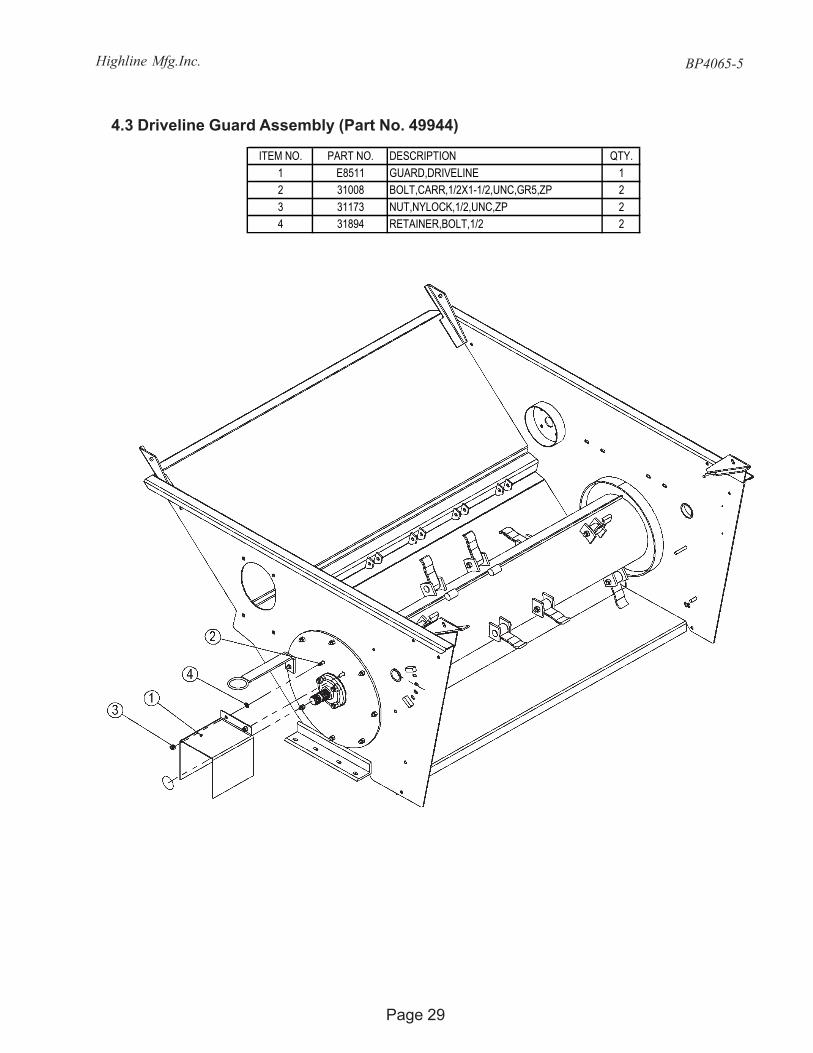
4.3 Driveline Guard Assembly (Part No. 49944)
ITEM NO. PART NO. DESCRIPTION QTY.1 E8511 GUARD,DRIVELINE 12 31008 BOLT,CARR,1/2X1-1/2,UNC,GR5,ZP 23 31173 NUT,NYLOCK,1/2,UNC,ZP 24 31894 RETAINER,BOLT,1/2 2

Highline Mfg.Inc. BP4065-5
Page 30
4.4 Flail Drum Installation (Part No. 49933)
ITEM NO. PART NO. DESCRIPTION QTY.1 49659 WLDT,HOLDER,HOSE 12 49908 ASSY,FLAIL DRUM 13 49918 WLDT,PLT,INSTALL,FLAIL_DRUM 14 33655 BEARING,CARTRIDGE,FLANGE,1-3/4" 25 31008 BOLT,CARR,1/2X1-1/2,UNC,GR5,ZP 86 31173 NUT,NYLOCK,1/2,UNC,ZP 77 30611 NUT,NYLOCK,JAM,1/2,UNC,ZP 18 31178 NUT,NYLOCK,5/8,UNC,ZP 89 31894 RETAINER,BOLT,1/2 810 E6982 SPACER,BEARING,DRUM.FLAIL 1

Highline Mfg.Inc.
Page 31
BP4065-5
4.4.1 Flail Drum Assembly (Part No. 49908)
ITEM NO. PART NO. DESCRIPTION QTY.1 49907 WLDT,DRUM,FLAIL,6',1 3/4 EXT SPLINE 12 E2083 PIPE,DOM,1x.180x2-1/8L,HARD 123 E3714 FLAIL 124 33696 BOLT,CARR,5/18X3-3/4,UNF,GR8,BLACK 125 31170 NUT,LOCK,STOVER,5/8,UNF,ZP 12

Highline Mfg.Inc. BP4065-5
Page 32
4.5 Flail Guard Rod Assembly (Part No. 49934)ITEM NO. PART NO. DESCRIPTION QTY.
1 49516 WLDT,PIN, ADJUSTMENT,FGR 12 49921 WLDT,BAR,ADJ,GUARD,FLAIL 13 49928 WLDT,HANDLE,FGR 14 49947 WLDT,GUARD_ROD 65 31668 WASHER,SPRING,3/4,342 46 92127 COVER,VINYL,3/8X1-1/2 17 31009 BOLT,CARR,1/2X2,UNC,GR5,ZP 18 31021 BOLT,HEX,1/2X3,UNC,GR5,ZP 19 31058 BOLT,HEX,9/16X3-1/2,UNC,GR5,ZP 1210 31173 NUT,NYLOCK,1/2,UNC,ZP 211 31179 NUT,NYLOCK,9/16,UNC,ZP 1212 31236 WASHER,FLAT,1/2,ZP 113 31242 WASHER,FLAT,9/16,ZP 12

Highline Mfg.Inc.
Page 33
BP4065-5
4.6 Bale Defelctor Assembly (Part No. 49935)
ITEM NO. PART NO. DESCRIPTION QTY.1 49910 WLDT,BALE_SHIELD 12 49912 WLDT,BALE_SHIELD,DISCHARGE 13 E8257 TUBE,SCREEN,BOTTOM 14 E8358 TUBE,SCREEN,TOP 15 31023 BOLT,HEX,1/2X3-1/2,UNC,GR5,ZP 126 31173 NUT,NYLOCK,1/2,UNC,ZP 127 31236 WASHER,FLAT,1/2,ZP 16

Highline Mfg.Inc. BP4065-5
Page 34
4.7 Bottom Discharge Door Assembly (Part No. 49936)
ITEM NO. PART NO. DESCRIPTION QTY.1 49924 WLDT,BOTTOM DIS DOOR 12 32998 SPRING,1.5X2.50X0.135 13 31021 BOLT,HEX,1/2X3,UNC,GR5,ZP 14 31173 NUT,NYLOCK,1/2,UNC,ZP 15 33889 WASHER,FLAT,1/2X2OD,ZP 1

Highline Mfg.Inc.
Page 35
BP4065-5
4.8 Hydraulic Assembly (Part No. 49938)ITEM NO. PART NO. DESCRIPTION QTY.
1 30204 HYD,FIT,ADAPTER,10MB-8MJ 22 30209 HYD,FIT,PIONEER,MALE,8FP 43 30210 HYD,CLAMP,HOSE,1/2 84 30211 HYD,FIT,ELBOW,8MB-8MJ90 25 33893 HYD,HOSE,1/2X102,8MP-8FJX,2W 26 33894 HYD,HOSE,3/8X234,8MP-8FJX,2W 27 31176 NUT,NYLOCK,3/8,UNC,ZP 48 31351 WASHER,FLAT,3/8,ZP 4

Highline Mfg.Inc. BP4065-5
Page 36
4.9A Loading Forks and Frame Assembly (Part No. 49937) USE FOR MACHINES UP TO AND INCLUDING SERIAL NUMBER BP40650755
ITEM NO. PART NO. DESCRIPTION QTY.1 33866 HYD,CYL,SEALKIT,4x2 12 33867 HYD,CYL,TUBE,4X16,8FB,IL 13 33868 HYD,CYL,NUT 14 33869 HYD,CYL,PISTON,4 15 33870 HYD,CYL,ROD,2X16,WLDCLV,1.5P 16 33871 HYD,CYL,CAP,ROD,4X2 1
4.9.1 Cylinder Assembly (Part No. 33800)
ITEM NO. PART NO. DESCRIPTION QTY.1 49379 PIN,FLOAT,FORK 22 49668 WLDT,PIN,CYL,1X4-5/16U 13 49665 PIN,ANTIROTATE,1-1/2X5-9/16 14 49906 FRAME,LIFT 15 49919 PIN,ANTIROTATE,1-3/4DIA 16 33800 HYD,CYL,4.0X16,CLVXTUBE,8FBIL 17 49948 WLDT,FORK,RIGHT 18 49949 WLDT,FORK,LEFT 19 E6250 PLT,ANTIROTATION,1-1/2D 110 E6087 BUSHING,PIN,FORK,HOLE 211 E8521 LOCK,CYL,CHANNEL 112 30207 ZERK,1/4-28,GF641,STRAIGHT 113 31813 PIN,QUICK RELEASE,1/2X3,ZP 114 31183 PIN,COTTER,3/16X2 115 31017 BOLT,HEX,1/2X1-3/4,UNC,GR5,ZP 116 31020 BOLT,HEX,1/2X2-3/4,UNC,GR5,ZP 217 31599 BOLT,HEX,1/2X6-1/2,UNC,GR5,ZP 118 31173 NUT,NYLOCK,1/2,UNC,ZP 419 31236 WASHER,FLAT,1/2,ZP 3

Highline Mfg.Inc.
Page 37
BP4065-5
Highline Mfg.Inc. BP4065-5
Page 38
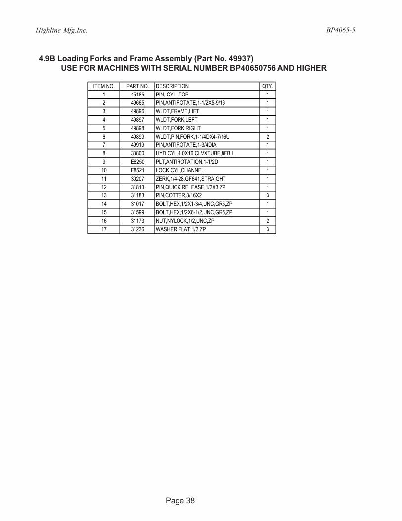
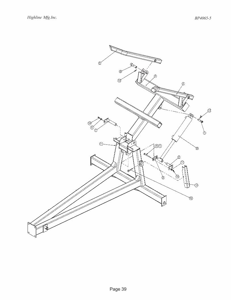
4.9B Loading Forks and Frame Assembly (Part No. 49937) USE FOR MACHINES WITH SERIAL NUMBER BP40650756 AND HIGHER
ITEM NO. PART NO. DESCRIPTION QTY.1 45185 PIN, CYL, TOP 12 49665 PIN,ANTIROTATE,1-1/2X5-9/16 13 49896 WLDT,FRAME,LIFT 14 49897 WLDT,FORK,LEFT 15 49898 WLDT,FORK,RIGHT 16 49899 WLDT,PIN,FORK,1-1/4DX4-7/16U 27 49919 PIN,ANTIROTATE,1-3/4DIA 18 33800 HYD,CYL,4.0X16,CLVXTUBE,8FBIL 19 E6250 PLT,ANTIROTATION,1-1/2D 110 E8521 LOCK,CYL,CHANNEL 111 30207 ZERK,1/4-28,GF641,STRAIGHT 112 31813 PIN,QUICK RELEASE,1/2X3,ZP 113 31183 PIN,COTTER,3/16X2 314 31017 BOLT,HEX,1/2X1-3/4,UNC,GR5,ZP 115 31599 BOLT,HEX,1/2X6-1/2,UNC,GR5,ZP 116 31173 NUT,NYLOCK,1/2,UNC,ZP 217 31236 WASHER,FLAT,1/2,ZP 3
Highline Mfg.Inc.
Page 39
BP4065-5

Highline Mfg.Inc. BP4065-5
Page 40
4.10 Upper Discharge Door Assembly (Part No. 49942)
ITEM NO. PART NO. DESCRIPTION QTY.1 49925 WLDT,FRAME,DOOR,CANVAS 12 49926 WLDT,FRAME,INNER_DOOR 13 49658 WLDT,BAR,WEIGHT 14 70632 TETHER,CABLE,12" 15 E8378 PIPE,ATTACH,CANVAS 26 31810 GRIP,HANDLE,1-1/4IDX4-1/2 17 33839 TARP,50X68-3/4,3_PKT,DISCHARGE 18 33862(11.1) CHAIN,GR 30,3/16E,1.06X.45ID,ZP 19 33863 CHAIN,LAP_LINK,3/16,ZP 210 33873 PIN,HITCH,.2X3.625,DBL_LOOP,ZP 111 31345 BOLT,HEX,3/8X3/4,UNC,GR5,ZP 212 31067 BOLT,HEX,3/8X2,UNC,GR5,ZP 813 31016 BOLT,HEX,1/2X1-1/2,UNC,GR5,ZP 214 31023 BOLT,HEX,1/2X3-1/2,UNC,GR5,ZP 115 31028 BOLT,HEX,1/2X5,UNC,GR5,ZP 116 31176 NUT,NYLOCK,3/8,UNC,ZP 817 31173 NUT,NYLOCK,1/2,UNC,ZP 418 31351 WASHER,FLAT,3/8,ZP 1019 31236 WASHER,FLAT,1/2,ZP 4
NOTE: PART NUMBER 70632 NOT USED IN MACHINES WITH SERIALNUMBER BP40650756 AND HIGHER
Note:Mount Chain with 20 Linksbetween the door frameand the canvas weight bar.

Highline Mfg.Inc.
Page 41
BP4065-5

Highline Mfg.Inc. BP4065-5
Page 42
4.11A Tire, Hitch and Jack Assembly (Part No. 49945) USE FOR MACHINES UP TO AND INCLUDING SERIAL NUMBER BP40650755
ITEM NO. PART NO. DESCRIPTION QTY.1 45224 SUSP,HUB,H611,3600lbs 22 49089 WHEEL,COMPLETE,BP,OFF-WHITE 23 49946 WLDT,SPINDLE,BOLT_ON 24 E6546 ANGLE,BRIDLE,HITCH,LT 25 31861 HITCH,BASE,3 IN 1 16 33835 JACK,2000LBX10,RND MNT,TOPWIND 17 31016 BOLT,HEX,1/2X1-1/2,UNC,GR5,ZP 48 31339 BOLT,HEX,3/4X2,UNC,GR5,ZP 49 31042 BOLT,HEX,3/4X6,UNC,GR5,ZP 210 31173 NUT,NYLOCK,1/2,UNC,ZP 411 31167 NUT,HEX,3/4,UNC,GR5,ZP 612 31246 WASHER,LOCK,3/4,ZP 6

Highline Mfg.Inc.
Page 43
BP4065-5
4.11B Tire, Hitch and Jack Assembly (Part No. 49945) USE FOR MACHINES WITH SERIAL NUMBER BP40650756 AND HIGHER
ITEM NO. PART NO. DESCRIPTION QTY.1 45224 SUSP,HUB,H611,3600lbs 22 49895 WHEEL,COMP,11L15,6,FU,WH 23 49946 WLDT,SPINDLE,BOLT_ON 24 E6546 ANGLE,BRIDLE,HITCH,LT 25 31861 HITCH,BASE,3 IN 1 16 33835 JACK,2000LBX10,RND MNT,TOPWIND 17 31016 BOLT,HEX,1/2X1-1/2,UNC,GR5,ZP 48 31339 BOLT,HEX,3/4X2,UNC,GR5,ZP 49 31042 BOLT,HEX,3/4X6,UNC,GR5,ZP 210 31173 NUT,NYLOCK,1/2,UNC,ZP 411 31167 NUT,HEX,3/4,UNC,GR5,ZP 612 31246 WASHER,LOCK,3/4,ZP 6

Highline Mfg.Inc. BP4065-5
Page 44
4.11.1 Hub Assembly (Part No. 45224)ITEM NO. PART NO. DESCRIPTION QTY.
1 30346 OIL SEAL 12 30344 BRG, 1-1/2, 611 HUB 13 30373 SUSP,HUB,H611 14 30345 SUSP,BRG,1-1/4,611 HUB 15 30342 SUSP,CAP,DUST,611 HUB 16 32336 SUSP,BOLT,WHEEL,1/2x1-1/4x1-3/4L 67 91150 SUSP,BRG,RACE,LM29710 18 91130 SUSP,BRG,RACE,LM67010 19 30207 ZERK,1/4-28,GF641,STRAIGHT 1
4.11A.2 Tire Assembly (Part No. 49089)
ITEM NO. PART NO. DESCRIPTION QTY.1 45222 SUSP,TIRE,11LX15FI,6PLY 12 45223 SUSP,WHEEL,15X9LB,1.12OFF,6 13 91048 SUSP,STEM,VALVE,TR801HP 1
4.11B.2 Tire Assembly (Part No. 49895)
ITEM NO. PART NO. DESCRIPTION QTY.1 33383 SUSP,TIRE,11L15FU,8PLY 12 45223 SUSP,WHEEL,15X9LB,1.12OFF,6 13 91048 SUSP,STEM,VALVE,TR801HP 1
Highline Mfg.Inc.
Page 45
BP4065-5
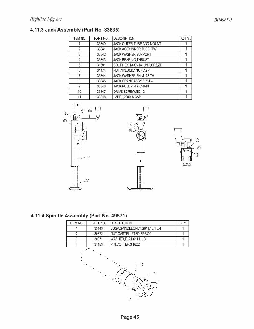
4.11.3 Jack Assembly (Part No. 33835)
ITEM NO. PART NO. DESCRIPTION QTY.1 33143 SUSP,SPINDLEONLY,S611,10,1 3/4 12 30372 NUT,CASTELLATED,BP6800 13 30371 WASHER,FLAT,611 HUB 14 31183 PIN,COTTER,3/16X2 1
4.11.4 Spindle Assembly (Part No. 49571)
ITEM NO. PART NO. DESCRIPTION QTY.1 33840 JACK,OUTER TUBE AND MOUNT 12 33841 JACK,ASSY INNER TUBE (TW) 13 33842 JACK,WASHER,SUPPORT 14 33843 JACK,BEARING,THRUST 15 31581 BOLT,HEX,1/4X1-1/4,UNC,GR5,ZP 16 31174 NUT,NYLOCK,1/4UNC,ZP 17 33844 JACK,WASHER,SHIM-.03 TH 18 33845 JACK,CRANK ASSY,6.75TW 19 33846 JACK,PULL PIN & CHAIN 110 33847 DRIVE SCREW,NO.12 111 33848 LABEL,2000 lb CAP 1
5
11
6 8
1
2
9
10
7
4
3

Highline Mfg.Inc. BP4065-5
Page 46
5.1 Standard PTO Option (Part No. BPO4PTO-5)
5.0 Options
5.1.1 Standard PTO (Part No. 33836)
ITEM NO. PART NO. DESCRIPTION QTY.1 33836 DRV,DL,UJ,35R,34.5COMP 1
ITEM NO. PART NO. DESCRIPTION QTY.1 30352 KIT,REPAIR,LOCK,AUTO 12 33852 SAFETY SLIDE LOCK YOKE ASSY 13 30365 DRV,DL,U-JOINT,CROSS&BEARING,35R 24 33853 YOKE & SHAFT(1.19 SQ) 15 33811 NYLON REPAIR KIT 26 30359 SIGN,SAFETY 17 33859 OUTER GUARD 18 33860 INNER GUARD 19 30363 SAFETY SIGN 110 33854 YOKE,TUBE & SLIP SLEEVE 111 33855 BALL SHEAR ASSY 112 30367 3/8X2-16 GR5 BOLT 113 30368 3/8-16 LOCK NUT 114 33856 AUTO-LOK/SSL REPAIR KIT 115 33857 J&S HALF ASSY W GUARD16 33858 J&T HALF ASSY W GUARD17 33861 GUARD SET
15 17 16
Highline Mfg.Inc.
Page 47
BP4065-5
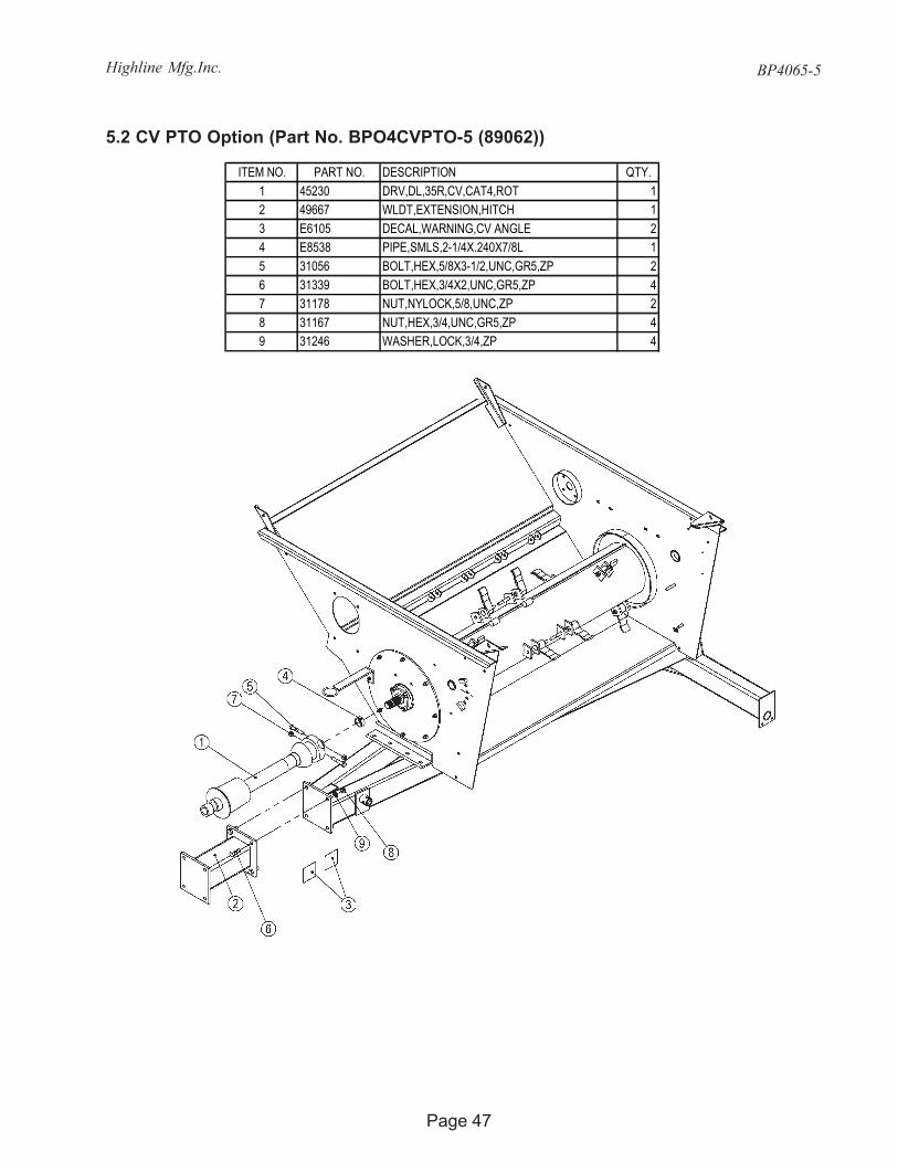
5.2 CV PTO Option (Part No. BPO4CVPTO-5 (89062))
ITEM NO. PART NO. DESCRIPTION QTY.1 45230 DRV,DL,35R,CV,CAT4,ROT 12 49667 WLDT,EXTENSION,HITCH 13 E6105 DECAL,WARNING,CV ANGLE 24 E8538 PIPE,SMLS,2-1/4X.240X7/8L 15 31056 BOLT,HEX,5/8X3-1/2,UNC,GR5,ZP 26 31339 BOLT,HEX,3/4X2,UNC,GR5,ZP 47 31178 NUT,NYLOCK,5/8,UNC,ZP 28 31167 NUT,HEX,3/4,UNC,GR5,ZP 49 31246 WASHER,LOCK,3/4,ZP 4
Highline Mfg.Inc. BP4065-5
Page 48
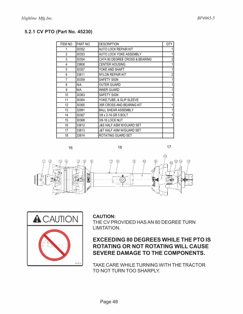
5.2.1 CV PTO (Part No. 45230)
ITEM NO. PART NO. DESCRIPTION QTY.1 30352 AUTO LOCK REPAIR KIT 12 30353 AUTO LOCK YOKE ASSEMBLY 13 30354 CAT4 80 DEGREE CROSS & BEARING 24 33806 CENTER HOUSING 15 30357 YOKE AND SHAFT 16 33811 NYLON REPAIR KIT 27 30359 SAFETY SIGN 18 N/A OUTER GUARD 19 N/A INNER GUARD 110 30363 SAFETY SIGN 111 30364 YOKE,TUBE, & SLIP SLEEVE 112 30365 35R CROSS AND BEARING KIT 113 32991 BALL SHEAR ASSEMBLY 114 30367 3/8 x 2-16 GR 5 BOLT 115 30368 3/8-16 LOCK NUT 116 33812 J&S HALF ASM W/GUARD SET17 33813 J&T HALF ASM W/GUARD SET18 33814 ROTATING GUARD SET
>80°
E6105_B
CAUTION:THE CV PROVIDED HAS AN 80 DEGREE TURNLIMITATION.
EXCEEDING 80 DEGREES WHILE THE PTO ISROTATING OR NOT ROTATING WILL CAUSESEVERE DAMAGE TO THE COMPONENTS.
TAKE CARE WHILE TURNING WITH THE TRACTORTO NOT TURN TOO SHARPLY.
16 18 17

Highline Mfg.Inc.
Page 49
BP4065-5
This page intentionally left blank.

Highline Mfg.Inc. BP4065-5
Page 50
5.4 Hitch Clevis Option (Part No. BPOHC-4 (89004))

Highline Mfg.Inc.
Page 51
BP4065-5
5.5 Flow Control Option (Part No. BPOFC-4 (89005))
5.6 Safety Chain Option (Part No. BPOSC-4 (89006))
Highline Mfg.Inc. BP4065-5
Page 52
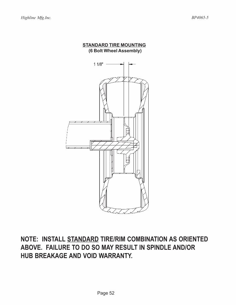
NOTE: INSTALL STANDARD TIRE/RIM COMBINATION AS ORIENTEDABOVE. FAILURE TO DO SO MAY RESULT IN SPINDLE AND/ORHUB BREAKAGE AND VOID WARRANTY.
STANDARD TIRE MOUNTING(6 Bolt Wheel Assembly)

Highline Mfg.Inc.
Page 53
BP4065-5
This page intentionally left blank.

Highline Mfg.Inc. BP4065-5
Page 54
6.0 Parts IndexPart# Description Page
Part# Description Page
30204 HYD,FIT,ADAPTER,10MB-8MJ 3530207 ZERK,1/4-28,GF641,STRAIGHT 3630207 ZERK,1/4-28,GF641,STRAIGHT 3830207 ZERK,1/4-28,GF641,STRAIGHT 4430208 PLT,SERIAL# 1630209 HYD,FIT,PIONEER,MALE,8FP 3530210 HYD,CLAMP,HOSE,1/2 3530211 HYD,FIT,ELBOW,8MB-8MJ90 3530271 DECAL,DANGER,ROTATING DRIVE 1630285 DECAL,DANGER,TO PREVENT 1630288 RIVET,ST,1/8X.390,.250HEAD 1630294 SCREW,TEK,1/4X1 2730342 SUSP,CAP,DUST,611 HUB 4430344 BRG, 1-1/2, 611 HUB 4430345 SUSP,BRG,1-1/4,611 HUB 4430346 OIL SEAL 4430352 KIT,REPAIR,LOCK,AUTO 4630352 AUTO LOCK REPAIR KIT 4830353 AUTO LOCK YOKE ASSEMBLY 4830354 CAT4 80 DEGREE CROSS & BEARING 4830357 YOKE AND SHAFT 4830359 SIGN,SAFETY 4630359 SAFETY SIGN 4830363 SAFETY SIGN 4630363 SAFETY SIGN 4830364 YOKE,TUBE, & SLIP SLEEVE 4830365 DRV,DL,U-JOINT,CROSS&BEARING,35R 4630365 35R CROSS AND BEARING KIT 4830367 3/8X2-16 GR5 BOLT 4630367 3/8 x 2-16 GR 5 BOLT 4830368 3/8-16 LOCK NUT 4630368 3/8-16 LOCK NUT 4830371 WASHER,FLAT,611 HUB 4530372 NUT,CASTELLATED,BP6800 4530373 SUSP,HUB,H611 4430577 DECAL,RED REFL,2X9 1630578 DECAL,AMBER REFL,2X9 1630611 NUT,NYLOCK,JAM,1/2,UNC,ZP 3031008 BOLT,CARR,1/2X1-1/2,UNC,GR5,ZP 2931008 BOLT,CARR,1/2X1-1/2,UNC,GR5,ZP 3031009 BOLT,CARR,1/2X2,UNC,GR5,ZP 3231012 BOLT,CARR,1/4X1,UNC,GR5,ZP 2631016 BOLT,HEX,1/2X1-1/2,UNC,GR5,ZP 2431016 BOLT,HEX,1/2X1-1/2,UNC,GR5,ZP 2631016 BOLT,HEX,1/2X1-1/2,UNC,GR5,ZP 2731016 BOLT,HEX,1/2X1-1/2,UNC,GR5,ZP 4031016 BOLT,HEX,1/2X1-1/2,UNC,GR5,ZP 4231016 BOLT,HEX,1/2X1-1/2,UNC,GR5,ZP 4331017 BOLT,HEX,1/2X1-3/4,UNC,GR5,ZP 2531017 BOLT,HEX,1/2X1-3/4,UNC,GR5,ZP 2731017 BOLT,HEX,1/2X1-3/4,UNC,GR5,ZP 3631017 BOLT,HEX,1/2X1-3/4,UNC,GR5,ZP 3831020 BOLT,HEX,1/2X2-3/4,UNC,GR5,ZP 3631021 BOLT,HEX,1/2X3,UNC,GR5,ZP 3231021 BOLT,HEX,1/2X3,UNC,GR5,ZP 3431023 BOLT,HEX,1/2X3-1/2,UNC,GR5,ZP 3331023 BOLT,HEX,1/2X3-1/2,UNC,GR5,ZP 4031028 BOLT,HEX,1/2X5,UNC,GR5,ZP 40
31351 WASHER,FLAT,3/8,ZP 3531351 WASHER,FLAT,3/8,ZP 4031486 BOLT,HEX,3/4X5,UNC,GR5,ZP 5031581 BOLT,HEX,1/4X1-1/4,UNC,GR5,ZP 4531590 CHAIN,SAFETY,ASAE,10100LB,5'4" 5131599 BOLT,HEX,1/2X6-1/2,UNC,GR5,ZP 3631599 BOLT,HEX,1/2X6-1/2,UNC,GR5,ZP 3831668 WASHER,SPRING,3/4,342 3231810 GRIP,HANDLE,1-1/4IDX4-1/2 4031813 PIN,QUICK RELEASE,1/2X3,ZP 3631813 PIN,QUICK RELEASE,1/2X3,ZP 3831861 HITCH,BASE,3 IN 1 4231861 HITCH,BASE,3 IN 1 4331862 CLEVIS,HITCH,3 IN 1 5031894 RETAINER,BOLT,1/2 2931894 RETAINER,BOLT,1/2 3031945 BOLT,U,SQ,1/2-13X4X7-1/2 2432082 HYD,FIT,ADAPTOR,8MP-8MP 5132336 SUSP,BOLT,WHEEL,1/2x1-1/4x1-3/4L 4432639 BEARING,THRUST,FRONT 2832647 SEAL KIT,ROLLER STATOR 2832649 BEARING,HOUSING,REAR,1/2 2832651 BEARING,THRUST,REAR 2832653 SHAFT KIT 2832720 BEARING,HOUSING,FRONT 2832722 DRIVE LINK KIT 2832725 SHAFT KIT 2832726 BALANCE PLATE & BALLS 2832727 END COVER 2832734 WASHER,FLAT,3-1/8ODX1/2 2632734 WASHER,FLAT,3-1/8ODX1/2 2732975 HYD,VALVE,CONTROL,FLOW,8FP 5132981 DECAL,PIMA 1632991 BALL SHEAR ASSEMBLY 4832998 SPRING,1.5X2.50X0.135 3433143 SUSP,SPINDLEONLY,S611,10,1 3/4 4533377 HYD,MOTOR,22.8,3000PSI 2633377 HYD,MOTOR,22.8,3000PSI 2733383 SUSP,TIRE,11L15FU,8PLY 4433652 ROTOR KIT 2833653 HOUSING KIT 2833654 BOLT KIT 2833655 BEARING,CARTRIDGE,FLANGE,1-3/4" 2533655 BEARING,CARTRIDGE,FLANGE,1-3/4" 2733655 BEARING,CARTRIDGE,FLANGE,1-3/4" 3033656 BEARING,INSRT,1-3/4 B,85mmOD 2633656 BEARING,INSRT,1-3/4 B,85mmOD 2733658 DRV,SPRKT,#80,24,1-3/4-20SPL 2633658 DRV,SPRKT,#80,24,1-3/4-20SPL 2733659 CHAIN,CONNECTOR_LINK,#80 2633659 CHAIN,CONNECTOR_LINK,#80 2733679 SPRING,EXT,31/64ODX5-1/4X.063 2633696 BOLT,CARR,5/18X3-3/4,UNF,GR8,BLACK 3133800 HYD,CYL,4.0X16,CLVXTUBE,8FBIL 3633800 HYD,CYL,4.0X16,CLVXTUBE,8FBIL 3833806 CENTER HOUSING 4833811 NYLON REPAIR KIT 4633811 NYLON REPAIR KIT 4833812 J&S HALF ASM W/GUARD SET 48
Highline Mfg.Inc.
Page 55
BP4065-5
Part# Description PagePart# Description Page33813 J&T HALF ASM W/GUARD SET 4833814 ROTATING GUARD SET 4833835 JACK,2000LBX10,RND MNT,TOPWIND 4233835 JACK,2000LBX10,RND MNT,TOPWIND 4333835 JACK,2000LBX10,RND MNT,TOPWIND 4533836 DRV,DL,UJ,35R,34.5COMP 4633839 TARP,50X68-3/4,3_PKT,DISCHARGE 4033840 JACK,OUTER TUBE AND MOUNT 4533841 JACK,ASSY INNER TUBE (TW) 4533842 JACK,WASHER,SUPPORT 4533843 JACK,BEARING,THRUST 4533844 JACK,WASHER,SHIM-.03 TH 4533845 JACK,CRANK ASSY,6.75TW 4533846 JACK,PULL PIN & CHAIN 4533847 DRIVE SCREW,NO.12 4533848 LABEL,2000 lb CAP 4533852 SAFETY SLIDE LOCK YOKE ASSY 4633853 YOKE & SHAFT(1.19 SQ) 4633854 YOKE,TUBE & SLIP SLEEVE 4633855 BALL SHEAR ASSY 4633856 AUTO-LOK/SSL REPAIR KIT 4633857 J&S HALF ASSY W GUARD 4633858 J&T HALF ASSY W GUARD 4633859 OUTER GUARD 4633860 INNER GUARD 4633861 GUARD SET 4633863 CHAIN,LAP_LINK,3/16,ZP 4033866 HYD,CYL,SEALKIT,4x2 3633867 HYD,CYL,TUBE,4X16,8FB,IL 3633868 HYD,CYL,NUT 3633869 HYD,CYL,PISTON,4 3633870 HYD,CYL,ROD,2X16,WLDCLV,1.5P 3633871 HYD,CYL,CAP,ROD,4X2 3633873 PIN,HITCH,.2X3.625,DBL_LOOP,ZP 4033889 WASHER,FLAT,1/2X2OD,ZP 3433893 HYD,HOSE,1/2X102,8MP-8FJX,2W 3533894 HYD,HOSE,3/8X234,8MP-8FJX,2W 3545185 PIN, CYL, TOP 3845222 SUSP,TIRE,11LX15FI,6PLY 4445223 SUSP,WHEEL,15X9LB,1.12OFF,6 4445223 SUSP,WHEEL,15X9LB,1.12OFF,6 4445224 SUSP,HUB,H611,3600lbs 4245224 SUSP,HUB,H611,3600lbs 4345230 DRV,DL,35R,CV,CAT4,ROT 4749089 WHEEL,COMPLETE,BP,OFF-WHITE 4249379 PIN,FLOAT,FORK 3649516 WLDT,PIN, ADJUSTMENT,FGR 3249658 WLDT,BAR,WEIGHT 4049659 WLDT,HOLDER,HOSE 3049665 PIN,ANTIROTATE,1-1/2X5-9/16 3649665 PIN,ANTIROTATE,1-1/2X5-9/16 3849667 WLDT,EXTENSION,HITCH 4749668 WLDT,PIN,CYL,1X4-5/16U 3649669 WLDT,TUB,BP4065 2449673 WLDT, FEED_ROLL 2749895 WHEEL,COMP,11L15,6,FU,WH 4349896 WLDT,FRAME,LIFT 3849897 WLDT,FORK,LEFT 3849898 WLDT,FORK,RIGHT 38
49899 WLDT,PIN,FORK,1-1/4DX4-7/16U 3849905 WLDT,FRAME,BP 2449906 FRAME,LIFT 3649907 WLDT,DRUM,FLAIL,6',1 3/4 EXT SPLINE 3149908 ASSY,FLAIL DRUM 3049910 WLDT,BALE_SHIELD 3349912 WLDT,BALE_SHIELD,DISCHARGE 3349913 WLDT, FEED_ROLL 2549916 WLDT,MOUNT,BRG_TWINE_MOTOR 2649917 ASSY,DRIVE,FEEDROLLER 2549918 WLDT,PLT,INSTALL,FLAIL_DRUM 3049919 PIN,ANTIROTATE,1-3/4DIA 3649919 PIN,ANTIROTATE,1-3/4DIA 3849921 WLDT,BAR,ADJ,GUARD,FLAIL 3249924 WLDT,BOTTOM DIS DOOR 3449925 WLDT,FRAME,DOOR,CANVAS 4049926 WLDT,FRAME,INNER_DOOR 4049928 WLDT,HANDLE,FGR 3249943 WLDT,PANEL,INNER 2449946 WLDT,SPINDLE,BOLT_ON 4249946 WLDT,SPINDLE,BOLT_ON 4349947 WLDT,GUARD_ROD 3249948 WLDT,FORK,RIGHT 3649949 WLDT,FORK,LEFT 3670632 TETHER,CABLE,12" 4075437 DRV,SPROCKET,COUPLING,SPLINE 2675437 DRV,SPROCKET,COUPLING,SPLINE 2789062 BP,OPTION,4065,CV_PTO 4791048 SUSP,STEM,VALVE,TR801HP 4491048 SUSP,STEM,VALVE,TR801HP 4491130 SUSP,BRG,RACE,LM67010 4491150 SUSP,BRG,RACE,LM29710 4492028 SIGN,SLOWMOVING,S276.5 1692094 DRV, BRG, FLANGE, 1-3/8" 2592094 DRV, BRG, FLANGE, 1-3/8" 2792127 COVER,VINYL,3/8X1-1/2 3292573 DECAL,WARNING,DISCHARGE 1692579 DECAL,HIGHLINE,4X30 16
33601(11.13) DECAL,PSTRP,11.13,YLW,1 1633834(11.13) DECAL,PSTRP,11.13,BLK,6 1633862(11.1) CHAIN,GR 30,3/16E,1.06X.45ID,ZP 40
E2083 PIPE,DOM,1x.180x2-1/8L,HARD 31E3265 DECAL,GREASEZERK,8H 16E3266 DECAL,GREASEZERK,16H 16E3714 FLAIL 31E3834 DECAL,DANGER,DO NOT STAND 16E5868 DECAL,LOCK,CYLINDER 16E6087 BUSHING,PIN,FORK,HOLE 36E6105 DECAL,WARNING,CV ANGLE 47E6150 PLT,C,1/4x13/16x2-1/4 51E6250 PLT,ANTIROTATION,1-1/2D 36E6250 PLT,ANTIROTATION,1-1/2D 38E6405 PIPE,SMLS,2-1/4x.240x1/4L 26E6546 ANGLE,BRIDLE,HITCH,LT 42E6546 ANGLE,BRIDLE,HITCH,LT 43E7386 GUARD,FEEDROLLER_CHAIN 26E7542 CHAIN,ROLLER,#80,15 LINKS 26E7552 DECAL,WARNING,OWNERS_MANUAL 16E7553 DECAL,WARNING,STOP_ENGINE/SERVICE 16

Highline Mfg.Inc. BP4065-5
Page 56
Part# Description PagePart# Description Page
E8054 BLOCK,GUIDE,CHAIN 26E8257 TUBE,SCREEN,BOTTOM 33E8358 TUBE,SCREEN,TOP 33E8378 PIPE,ATTACH,CANVAS 40E8511 GUARD,DRIVELINE 29E8517 DECAL,AGGRESSION,GUARD ROD 16E8521 LOCK,CYL,CHANNEL 36E8521 LOCK,CYL,CHANNEL 38E8538 PIPE,SMLS,2-1/4X.240X7/8L 47E8540 ANGLE,TURN,BALE 27E8585 CHAIN,ROLLER,#80,22 LINKS 27E8587 COVER,DRIVE,FROLL 27E8588 PLATE,GUARD,FINGER 27E8597 DECAL,BALEPRO_4065,7.2X29.6 16
Highline Mfg.Inc.
Page 57
BP4065-5
Horse Power Requirements (min): 55 HPCapacity: 2 bales - 6’ long x 6’ diameter - max. 2000 lbs
(907kg) each
Flail Drum Length: 72” (1.83m)Flail Drum Diameter: 26 3/4” swept diamter (67.9 cm) BalancedFlails: 12 flails - 7/16” x 5 9/16” Tempered Spring Steel
Tires: 2 - 11L X 15 - 8 ply Farm Utility (inflate to 36 psi)
Height - Forks Up: 121” (3.07m)Height - Top of Deflectors: 90” (2.29m)
Width - Tires: 93-3/4” (2.38m)Width - Overall: 101” (2.56m)
Length - Forks Down: 187-5/8” (4.77m)Length - Forks Up: 161” (4.09m)
Weight - Total: 2500 lbs (1134 kg)Hitch Weight (Empty): 851 lbs (386 kg)Hitch Weight (One bale in chamber): 1335 lbs (605.5 kg)
PTO Requirements: 1000 RPM PTO 1-3/8” - 21 spline shaftHydraulic Requirements 1500 psi @ 10 gpm - 2000 lb balesCylinder: 4” x 16”, 2” Rod DiameterHydraulic Motor: 22.8 cu in @ 3500 psi maximum intermittentFeed Roller Drive: #80 chain, 2:1 reduction
7.0 Specifications
Highline Mfg.Inc. BP4065-5
Page 58
Dealer Information
Dealer:
Address:
City:
Province / State:
Postal Code / Zip Code:
Phone:
Identification Numbers
Model Number:
Serial Number:

Highline Mfg.Inc.
Page 59
BP4065-5
Dealer Checklist
Packaged SERIAL NO.: ______________________________________________RTU
Options: BPO4065PTO-5 BPO4065CVPTO-5 BPOHC-5 BPOSC-5IQ N/A Check List Item
Flail rod adjustment handle moves freely and will hit all 4 adjustment holes. Bottom deflector door moves freely and will hit all 2 adjustment holes.Ensure all grease points are lubricated and grease point decals installedEnsure lift assembly is against frame when cylinders are retracted.Safety decals & reflective stripes installed per specifications and drawings.Check tire pressure as specified on tire.Full library of manuals (operators, and parts) shipped with machine (When applicable).Visually check for 1/2" Flail to Tub clearance - front and back of flail drum
IQ N/A PACKAGING LIST - Fork, left and Fork, right - PTO - Package screen tubes with hardware
IQ N/A OPERATIONAL CHECK - flail drum (not binding on twine guards) - flails not hitting tub or rods - test 1 in 10 using tractorFeed Rollers turn in both directionsEnsure free movement of BP forks (not binding).Ensure cylinder transport lock fits with forks in transport position. Hydraulic motor to be operated and checked for leaks and free movement.Cycle cylinder a minimum of 3 times, check for leaks and clearance problems.Dump - hits bottom stops with cylinders fully retracted

Highline Mfg.Inc. BP4065-5
Page 60

Highline Mfg.Inc.
Page 61
BP4065-5

Highline Mfg.Inc. BP4065-5
Page 62

Highline Mfg.Inc.
Page 63
BP4065-5

Highline Mfg.Inc. BP4065-5
Page 64

Highline Mfg.Inc.
Page 65
BP4065-5