PXI-4065 Specifications - National Instruments
14
SPECIFICATIONS PXI-4065 6½-Digit, ±300 V PXI Digital Multimeter These specifications apply to the PXI-4065. Contents Definitions................................................................................................................................. 1 Conditions................................................................................................................................. 2 DC Specifications..................................................................................................................... 2 DC System Speed Characteristics..................................................................................... 3 DC Accuracy Specifications............................................................................................. 3 DC Functions General Specifications............................................................................... 5 AC Specifications..................................................................................................................... 6 AC System Speed Characteristics..................................................................................... 6 AC Accuracy Specifications............................................................................................. 6 AC Functions General Specifications............................................................................... 7 Temperature Accuracy Specifications...............................................................................8 General Specifications.............................................................................................................. 9 Input Protection Characteristics...................................................................................... 10 Calibration Interval......................................................................................................... 10 Warm-Up Time Characteristics....................................................................................... 10 Trigger Characteristics.................................................................................................... 10 Power Consumption Characteristics............................................................................... 11 Physical Characteristics...................................................................................................11 Environment............................................................................................................................ 11 Operating Environment................................................................................................... 11 Storage Environment.......................................................................................................12 Shock and Vibration........................................................................................................ 12 Compliance and Certifications................................................................................................ 12 Safety.............................................................................................................................. 12 Electromagnetic Compatibility....................................................................................... 13 CE Compliance .............................................................................................................. 13 Online Product Certification........................................................................................... 13 Environmental Management........................................................................................... 13 Definitions Warranted specifications describe the performance of a model under stated operating conditions and are covered by the model warranty.
Transcript of PXI-4065 Specifications - National Instruments

SPECIFICATIONS
PXI-40656½-Digit, ±300 V PXI Digital Multimeter
These specifications apply to the PXI-4065.
ContentsDefinitions.................................................................................................................................1Conditions................................................................................................................................. 2DC Specifications..................................................................................................................... 2
DC System Speed Characteristics.....................................................................................3DC Accuracy Specifications............................................................................................. 3DC Functions General Specifications............................................................................... 5
AC Specifications..................................................................................................................... 6AC System Speed Characteristics.....................................................................................6AC Accuracy Specifications............................................................................................. 6AC Functions General Specifications............................................................................... 7Temperature Accuracy Specifications...............................................................................8
General Specifications.............................................................................................................. 9Input Protection Characteristics...................................................................................... 10Calibration Interval......................................................................................................... 10Warm-Up Time Characteristics.......................................................................................10Trigger Characteristics.................................................................................................... 10Power Consumption Characteristics............................................................................... 11Physical Characteristics...................................................................................................11
Environment............................................................................................................................ 11Operating Environment................................................................................................... 11Storage Environment.......................................................................................................12Shock and Vibration........................................................................................................12
Compliance and Certifications................................................................................................12Safety.............................................................................................................................. 12Electromagnetic Compatibility....................................................................................... 13CE Compliance .............................................................................................................. 13Online Product Certification........................................................................................... 13Environmental Management........................................................................................... 13
DefinitionsWarranted specifications describe the performance of a model under stated operatingconditions and are covered by the model warranty.

Characteristics describe values that are relevant to the use of the model under stated operatingconditions but are not covered by the model warranty.• Typical specifications describe the expected performance met by a majority of the
models.• Nominal specifications describe parameters and attributes that may be useful in operation.
Specifications are Warranted unless otherwise noted.
ConditionsSpecifications are valid under the following conditions unless otherwise noted.• Ambient temperature of Tcal ± 5 °C.1
• Calibration interval of 1 year• 30 minutes minutes warm-up time• niDMM Digits Resolution property or NIDMM_ATTR_RESOLUTION_DIGITS
attribute set to 6.5• niDMM Aperture Time Units property or NIDMM_ATTR_APERTURE_TIME_UNITS
attribute set to Power Line Cycles• niDMM Aperture Time property or NIDMM_ATTR_APERTURE_TIME attribute set to
10
DC SpecificationsResolution (digits) Reading rate (S/s),
specified for 60 Hz (and50 Hz) operation
Aperture time(NPLC)
RMS noise (ppm ofrange), 10 V range
6½ 0.6 (0.5) 100 0.06
6 (5) 10 0.2
10 (8.33) 6 0.25
5½ 30 (25) 2 0.4
60 (50) 1 0.55
900 0.06 1.7
1,500 0.04 2.5
4½ 3,000 0.02 11.5
1 Tcal = temperature at which last external calibration was performed. NI factory calibration is 23 °C ± 1 °C.
2 | ni.com | PXI-4065 Specifications

Figure 1. Noise Performance2
0.01
0.1
1
10
100
0.01 0.1 1 10 100
Aperture Time (NPLC)
RM
S N
oise
(pp
m o
f Ran
ge)
DC System Speed CharacteristicsRange or function changes 10/s
Auto Range time, DC V 200 ms
Auto Range time, DC I 200 ms
Auto Range time, resistance 250 ms
Trigger latency <1 μs
Maximum trigger rate 2.5 kHz
DC Accuracy Specifications
Table 1. DC Voltage ± (ppm of Reading + ppm of Range)
Range Resolution Inputresistance
(10 MΩ,default),nominal
24 Hr4
Tcal5 ±1 °C
90 dayTcal
±5 °C
1 yearTcal
±5 °C
Tempco6 (ppm/°C)
100 mV3 100 nV >10 GΩ,10 MΩ
30 + 30 65 + 35 90 + 35 5 + 2
1 V 1 μV >10 GΩ,10 MΩ
20 + 8 65 + 12 90 + 12 5 + 1
10 V 10 μV >10 GΩ,10 MΩ
15 + 7 65 + 12 90 + 12 5 + 1
2 Measured on the 10 V range.3 With offset nulling.
PXI-4065 Specifications | © National Instruments | 3

Table 1. DC Voltage ± (ppm of Reading + ppm of Range) (Continued)
Range Resolution Inputresistance
(10 MΩ,default),nominal
24 Hr4
Tcal5 ±1 °C
90 dayTcal
±5 °C
1 yearTcal
±5 °C
Tempco6 (ppm/°C)
100 V 100 μV 10 MΩ 20 + 8 75 + 12 110+ 12
9 + 1
300 V 1 mV 10 MΩ 20 + 24 75 + 40 110+ 40
9 + 1
Table 2. DC Current ± (ppm of Reading + ppm of Range)
Range Resolution Burdenvoltage,typical
24 Hr4
Tcal5 ±1 °C
90 day Tcal
±5 °C1 year Tcal
±5 °CTempco6
(ppm/°C)
10 mA 10 nA <60 mV 50 + 100 300 + 200 500 + 200 30 + 20
100 mA 100 nA <0.6 V 100 + 40 300 + 50 500 + 50 30 + 5
1 A 1 μA <0.35 V 500 + 60 800 + 100 1,000+ 100
65 + 10
3 A 3 μA <1 V 1,0007 + 200 1,2007
+ 2001,2007
+ 20065 + 20
4 Relative to external calibration source. DMM must remain powered on.5 Tcal is the temperature at which last external calibration was performed. NI factory calibration is
23°C ±1°C.6 Tempco is the temperature coefficient in ppm of range per degree Celsius.7 Add 650 ppm/A of reading for currents above 1.5 A.
4 | ni.com | PXI-4065 Specifications
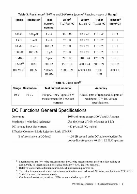
Table 3. Resistance8 (4-Wire and 2-Wire) ± (ppm of Reading + ppm of Range)
Range Resolution Testcurrent,nominal
24 Hr9
Tcal10 ±1 °C
90 dayTcal ±5 °C
1 yearTcal ±5 °C
Tempco6
(ppm/°C)
100 Ω 100 μΩ 1 mA 30 + 30 95 + 40 110 + 40 8 + 3
1 kΩ 1 mΩ 1 mA 20 + 8 95 + 20 110 + 20 8 + 1
10 kΩ 10 mΩ 100 μA 20 + 8 95 + 20 110 + 20 8 + 1
100 kΩ 100 mΩ 10 μA 20 + 8 95 + 20 110 + 20 8 + 1
1 MΩ 1 Ω 5 μA 20 + 12 110 + 24 125 + 24 10 + 1
10 MΩ11 10 Ω 500 nA 150 + 12 400 + 24 500 + 24 30 + 2
100 MΩ11 100 Ω 500 nA||10 MΩ
2,000 + 24 6,000 + 60 8,000+ 60
400 + 4
Table 4. Diode Test12
Range Resolution Test current, nominal Accuracy
10 V 10 μV 100 μA, 1 mA (up to 3.5 Vmeasurement for 1 mA test
current)
Add 50 ppm of range and 50 ppm ofreading to 10 V DC voltage
specifications.
DC Functions General SpecificationsOverrange 105% of range except 300 V and 3 A range
Maximum 4-wire lead resistance Use the lesser of 10% of range or 1 kΩ
DC voltage input bias current <40 pA at 23 °C, typical
Effective Common-Mode Rejection Ratio (CMRR)
(1 kΩ resistance in LO lead) >150 dB second order DC noise rejection (forpower-line frequency ±0.1%), 12 PLC aperture
8 Specifications are for 4-wire measurements. For 2-wire measurements, perform offset nulling oradd 200 mΩ to specification. For relative humidity >80%, add 100 ppm/MΩ.
9 Relative to external calibration source. DMM must remain powered on.10 Tcal is the temperature at which last external calibration was performed. NI factory calibration is 23°C ±1°C.11 2-wire resistance measurement only.12 Can be used to test p-n junctions, LEDs, or zener diodes up to 10 V.
PXI-4065 Specifications | © National Instruments | 5
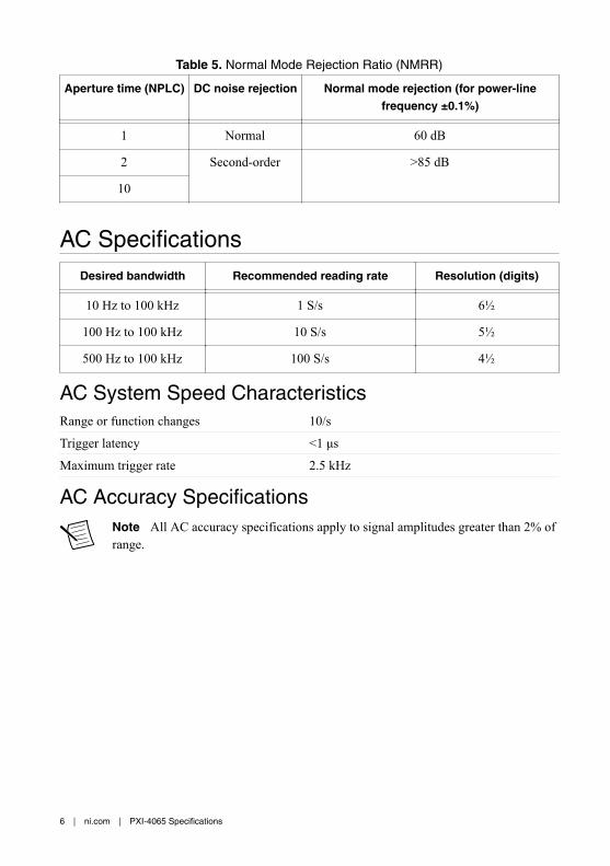
Table 5. Normal Mode Rejection Ratio (NMRR)
Aperture time (NPLC) DC noise rejection Normal mode rejection (for power-linefrequency ±0.1%)
1 Normal 60 dB
2 Second-order >85 dB
10
AC SpecificationsDesired bandwidth Recommended reading rate Resolution (digits)
10 Hz to 100 kHz 1 S/s 6½
100 Hz to 100 kHz 10 S/s 5½
500 Hz to 100 kHz 100 S/s 4½
AC System Speed CharacteristicsRange or function changes 10/s
Trigger latency <1 μs
Maximum trigger rate 2.5 kHz
AC Accuracy SpecificationsNote All AC accuracy specifications apply to signal amplitudes greater than 2% ofrange.
6 | ni.com | PXI-4065 Specifications

Table 6. AC Voltage (% of Reading + % of Range)
Range (peak voltage) Frequency 24 hr13
Tcal ±1 °C1 year14
Tcal ±5 °CTempco15
(%/°C)
200 mV (± 320 mV),2 V (± 3.2 V),20 V (± 32 V),
300 V (± 425 V)
10 Hz to 40 Hz 1.5 + 0.04 2 + 0.05 0.01 + 0.003
> 40 Hz to 20 kHz 0.2 + 0.04 0.2 + 0.05 0.01 + 0.003
> 20 kHz to 50 kHz 0.3 + 0.04 0.3 + 0.05 0.01 + 0.003
> 50 kHz to 100 kHz 1.5 + 0.08 1.5 + 0.08 0.02 + 0.005
Table 7. AC Current (% of Reading + % of Range)
Range (peak current) Frequency 24 hr13
Tcal ±1 °C1 year14
Tcal ±5 °CTempco15
(%/°C)
10 mA (± 16 mA),100 mA (± 160 mA),500 mA (± 780 mA),
3 A (± 4.25 A)
10 Hz to 40 Hz 1.6 to 0.05 2.1 + 0.05 0.015 + 0.03
> 40 Hz to5 kHz
0.3 + 0.05 0.3 + 0.06 0.015 + 0.03
Table 8. High Crest Factor Additional Error16
Crest factor Additional error (% of reading)
1 to 3 0.05%
3 to 4 0.1%
4 to 5 1% (for frequencies above 2 kHz)
AC Functions General SpecificationsInput impedance 10 MΩ in parallel with 200 pF, nominal
Input coupling AC coupling
Maximum Voltz-Hertz product 3 x 10⁷ V-Hz
Maximum DC voltage component 250 V
13 Tcal is the temperature at which last external calibration was performed. NI factory calibration is23°C ±1 °C.
14 Use the 1 Year specification to calibrate on a 90-day cycle.15 Tempco is the temperature coefficient. Tempco values are valid within the device's ambient
temperature range.16 Applicable for non-sinewave signals up to the rated peak voltage, current, or bandwidth.
PXI-4065 Specifications | © National Instruments | 7

CMRR, 1 kΩ resistance in LO lead 70 dB (DC to 60 Hz)
Overrange 105% of range except 300 V, 3 A range
Temperature Accuracy Specifications17
Table 9. Thermocouple Temperature Accuracy Specifications (°C)
Type Range 1 year Tcal ±5 °C Tempco(°Creading/°CDMM)20
Resolution
WithSimulated Ref.
Junction18
WithPXI-252719
J -150 to 1200 0.3 1.0 0.03 0.1
-210 to -150 0.4 1.2 0.03 0.1
K -100 to 1200 0.4 1.0 0.03 0.1
-200 to -100 0.4 1.5 0.03 0.1
N -100 to 1300 0.3 1.0 0.03 0.1
-200 to -100 0.6 1.5 0.03 0.1
T -100 to 400 0.3 1.0 0.03 0.1
-200 to -100 0.4 1.5 0.03 0.1
E -150 to 1000 0.2 1.0 0.03 0.1
-200 to -150 0.3 1.5 0.03 0.1
R 300 to 1760 0.6 1.8 0.06 0.1
-50 to 300 1.4 1.9 0.06 0.1
S 400 to 1760 0.7 1.8 0.06 0.1
-50 to 400 1.3 1.8 0.06 0.1
17 Tcal = temperature at which last external calibration was performed. NI factory calibration is 23°C±1 °C. For total measurement accuracy, add temperature probe error.
18 Using simulated reference junction.19 Includes PXI 2527 with TB 2627 with a typical 0.5 °C CJC error and a typical thermal EMF offset
of 2.5 μV for CJC temperatures between 15 °C and 35 °C. Add an additional 0.5 °C uncertaintywhen CJC is in the range 0 °C to 15 °C or 35 °C to 50 °C.
20 Tempco = Temperature coefficient, expressed in degrees of measurement uncertainty per degreechange in DMM instrument operating temperature.
8 | ni.com | PXI-4065 Specifications

Table 9. Thermocouple Temperature Accuracy Specifications (°C) (Continued)
Type Range 1 year Tcal ±5 °C Tempco(°Creading/°CDMM)20
Resolution
WithSimulated Ref.
Junction18
WithPXI-252719
B 1100 to 1820 0.6 1.8 0.09 0.1
400 to 1100 1.4 1.9 0.09 0.1
Table 10. RTD21 Temperature Accuracy Specifications (°C)
Range 1 year Tcal18 ±5 °C Tempco/°C22 Resolution
-200 to 600 0.17 0.011 0.01
Table 11. Thermistor Temperature Accuracy Specifications (°C)
Range 1 year Tcal18 ±5 °C Tempco/°C22 Resolution
-80 to 150 0.08 0.002 0.01
General SpecificationsMaximum common-mode voltage 300 V ACrms or DC
Measurement Category II
Caution Do not use this device for connection to signals or for measurementswithin Measurement Categories III or IV.
18 Using simulated reference junction.19 Includes PXI 2527 with TB 2627 with a typical 0.5 °C CJC error and a typical thermal EMF offset
of 2.5 μV for CJC temperatures between 15 °C and 35 °C. Add an additional 0.5 °C uncertaintywhen CJC is in the range 0 °C to 15 °C or 35 °C to 50 °C.
21 RTD with RO = 100 Ω Pt3851 RTD in a 4-wire configuration, using lowest possible resistancerange for each temperature.
22 Tempco is the temperature coefficient, expressed in degrees of measurement uncertainty perdegree change in DMM instrument operating temperature.
PXI-4065 Specifications | © National Instruments | 9

Input Protection CharacteristicsDC I and AC I 3.15 Amp, fused F 3.15 A 250 V, fast-acting
user-replaceable fuse
Resistance, diode Up to 300 V DC
DC V, AC V Up to 300 V DC, 300 V ACrms,450 V AC peak
Fuse When this fuse symbol is marked on a device, take proper precautions.
Hazardous Voltage This icon denotes a warning advising you to take precautionsto avoid electrical shock.
Calibration IntervalCalibration interval 1 year recommended
Warm-Up Time CharacteristicsWarm-up time 30 minutes to rated accuracy
Trigger CharacteristicsInput triggers
Types Trigger, Sample Trigger (programmable edge)
Sources Auxiliary connector (AUX I/O connector),PXI Trigger lines
Minimum pulse width 200 ns
Max samples per trigger 2.1 x 10⁹
Trigger delay 0 to 149 s
Logic level 5 V TTL, LVTTL
Output triggers
Types Measurement Complete (programmable edge)
Destinations Auxiliary connector (AUX I/O connector),PXI Trigger lines
Pulse width 1 μs
Logic level 3.3 V
Note The AUX I/O connector is not isolated. It is not referenced to yourmeasurement circuit. The connector is referenced to the ground of your chassis. Thedigital signals on this connector should not operate beyond -0.5 to 5.5 V of yourchassis ground. The trigger signals are TTL-compatible.
10 | ni.com | PXI-4065 Specifications
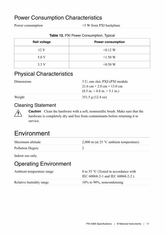
Power Consumption CharacteristicsPower consumption <3 W from PXI backplane
Table 12. PXI Power Consumption, Typical
Rail voltage Power consumption
12 V <0.12 W
5.0 V <1.50 W
3.3 V <0.50 W
Physical CharacteristicsDimensions 3 U, one slot, PXI/cPXI module
21.6 cm × 2.0 cm × 13.0 cm(8.5 in. × 0.8 in. × 5.1 in.)
Weight 351.5 g (12.4 oz)
Cleaning StatementCaution Clean the hardware with a soft, nonmetallic brush. Make sure that thehardware is completely dry and free from contaminants before returning it toservice.
EnvironmentMaximum altitude 2,000 m (at 25 °C ambient temperature)
Pollution Degree 2
Indoor use only.
Operating EnvironmentAmbient temperature range 0 to 55 °C (Tested in accordance with
IEC 60068-2-1 and IEC 60068-2-2.)
Relative humidity range 10% to 90%, noncondensing
PXI-4065 Specifications | © National Instruments | 11

Storage EnvironmentAmbient temperature range -40 °C to 70 °C (Tested in accordance
with IEC 60068-2-1 and IEC 60068-2-2.)
Relative humidity range 5% to 95%, noncondensing (Tested inaccordance with IEC 60068-2-56.)
Shock and VibrationOperational shock 30 g peak, half-sine, 11 ms pulse (Tested in
accordance with IEC 60068-2-27. Test profiledeveloped in accordance withMIL-PRF-28800F.)
Random vibration
Operating 5 Hz to 500 Hz, 0.3 grms (Tested in accordancewith IEC 60068-2-64.)
Nonoperating 5 Hz to 500 Hz, 2.4 grms (Tested in accordancewith IEC 60068-2-64. Test profile exceeds therequirements of MIL-PRF-28800F, Class 3.)
Compliance and CertificationsCaution You can impair the protection provided by the PXI-4065 if you use it in amanner not described in this document.
Caution This product is intended for use in industrial locations. As a result, thisproduct may cause interference if used in residential areas. Such use must beavoided unless the user takes special measures to reduce electromagnetic emissionsto prevent interference to the reception of radio and television broadcasts.
SafetyThis product is designed to meet the requirements of the following electrical equipment safetystandards for measurement, control, and laboratory use:• IEC 61010-1, EN 61010-1• UL 61010-1, CSA C22.2 No. 61010-1
Note For UL and other safety certifications, refer to the product label or the OnlineProduct Certification section.
12 | ni.com | PXI-4065 Specifications

Electromagnetic CompatibilityThis product meets the requirements of the following EMC standards for electrical equipmentfor measurement, control, and laboratory use:• EN 61326-1 (IEC 61326-1): Class A emissions; Basic immunity• EN 55011 (CISPR 11): Group 1, Class A emissions• EN 55022 (CISPR 22): Class A emissions• EN 55024 (CISPR 24): Immunity• AS/NZS CISPR 11: Group 1, Class A emissions• AS/NZS CISPR 22: Class A emissions• FCC 47 CFR Part 15B: Class A emissions• ICES-001: Class A emissions
Note In the United States (per FCC 47 CFR), Class A equipment is intended foruse in commercial, light-industrial, and heavy-industrial locations. In Europe,Canada, Australia, and New Zealand (per CISPR 11), Class A equipment is intendedfor use only in heavy-industrial locations.
Note Group 1 equipment (per CISPR 11) is any industrial, scientific, or medicalequipment that does not intentionally generate radio frequency energy for thetreatment of material or inspection/analysis purposes.
Note For EMC declarations, certifications, and additional information, refer to the Online Product Certification section.
CE Compliance This product meets the essential requirements of applicable European Directives, as follows:• 2014/35/EU; Low-Voltage Directive (safety)• 2014/30/EU; Electromagnetic Compatibility Directive (EMC)
Online Product CertificationRefer to the product Declaration of Conformity (DoC) for additional regulatory complianceinformation. To obtain product certifications and the DoC for this product, visit ni.com/certification, search by model number or product line, and click the appropriate link in theCertification column.
Environmental ManagementNI is committed to designing and manufacturing products in an environmentally responsiblemanner. NI recognizes that eliminating certain hazardous substances from our products isbeneficial to the environment and to NI customers.
For additional environmental information, refer to the Minimize Our Environmental Impactweb page at ni.com/environment. This page contains the environmental regulations and
PXI-4065 Specifications | © National Instruments | 13

directives with which NI complies, as well as other environmental information not included inthis document.
Waste Electrical and Electronic Equipment (WEEE)EU Customers At the end of the product life cycle, all NI products must bedisposed of according to local laws and regulations. For more information abouthow to recycle NI products in your region, visit ni.com/environment/weee.
电子信息产品污染控制管理办法(中国 RoHS)中国客户 National Instruments 符合中国电子信息产品中限制使用某些有害物
质指令(RoHS)。关于 National Instruments 中国 RoHS 合规性信息,请登录
ni.com/environment/rohs_china。(For information about China RoHScompliance, go to ni.com/environment/rohs_china.)
Information is subject to change without notice. Refer to the NI Trademarks and Logo Guidelines at ni.com/trademarks forinformation on NI trademarks. Other product and company names mentioned herein are trademarks or trade names of theirrespective companies. For patents covering NI products/technology, refer to the appropriate location: Help»Patents in yoursoftware, the patents.txt file on your media, or the National Instruments Patent Notice at ni.com/patents. You can findinformation about end-user license agreements (EULAs) and third-party legal notices in the readme file for your NI product. Referto the Export Compliance Information at ni.com/legal/export-compliance for the NI global trade compliance policy and howto obtain relevant HTS codes, ECCNs, and other import/export data. NI MAKES NO EXPRESS OR IMPLIED WARRANTIES ASTO THE ACCURACY OF THE INFORMATION CONTAINED HEREIN AND SHALL NOT BE LIABLE FOR ANY ERRORS. U.S.Government Customers: The data contained in this manual was developed at private expense and is subject to the applicablelimited rights and restricted data rights as set forth in FAR 52.227-14, DFAR 252.227-7014, and DFAR 252.227-7015.
© 2006—2017 National Instruments. All rights reserved.
374315J-01 Jan17