BACHELOR'S THESIS - DiVA portal
44
BACHELOR'S THESIS An Approach to Mobile Communication with Software Defined Radio Erik Persson 2013 Bachelor of Science in Engineering Technology Computer Engineering Luleå University of Technology Department of Computer Science, Electrical and Space Engineering
Transcript of BACHELOR'S THESIS - DiVA portal

BACHELOR'S THESIS
An Approach to Mobile Communicationwith Software Defined Radio
Erik Persson2013
Bachelor of Science in Engineering TechnologyComputer Engineering
Luleå University of TechnologyDepartment of Computer Science, Electrical and Space Engineering
An approach to mobile communication with Software
Defined Radio
Erik Persson
Lule̊a University of Technology2013-06-08
Abstract
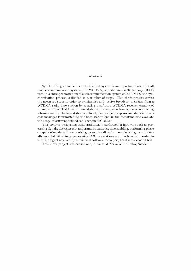
Synchronizing a mobile device to the host system is an important feature for allmobile communication systems. In WCDMA, a Radio Access Technology (RAT)used in a third generation mobile telecommunication system called UMTS, the syn-chronisation process is divided in a number of steps. This thesis project coversthe necessary steps in order to synchronise and receive broadcast messages from aWCDMA radio base station by creating a software WCDMA receiver capable oftuning in on WCDMA radio base stations, finding radio frames, detecting codingschemes used by the base station and finally being able to capture and decode broad-cast messages transmitted by the base station and in the meantime also evaluatethe usage of software defined radio within WCDMA.
This involves performing tasks traditionally performed in hardware such as pro-cessing signals, detecting slot and frame boundaries, descrambling, performing phasecompensation, detecting scrambling codes, decoding channels, decoding convolution-ally encoded bit strings, performing CRC calculations and much more in order toturn the signal received by a universal software radio peripheral into decoded bits.
This thesis project was carried out, in-house at Neava AB in Lule̊a, Sweden.
Preface
For me, studying WCDMA with Software Defined Radio has been an interesting journey,coming from a background with no previous knowledge in signal processing or radiotechnology. I want to thank Staffan Johansson at Neava AB for offering me the chanceof playing around with this technology and the rest of the Neava staff for helping meout during this project. I would also like to thank my wife and kids for their patienceand support.
Contents
1 Introduction 1
2 Method 22.1 Tools and hardware . . . . . . . . . . . . . . . . . . . . . . . . . . . . . . 2
2.1.1 Software Defined Radio . . . . . . . . . . . . . . . . . . . . . . . . 22.1.2 GNU Radio . . . . . . . . . . . . . . . . . . . . . . . . . . . . . . . 32.1.3 USRP N210 . . . . . . . . . . . . . . . . . . . . . . . . . . . . . . . 3
3 Introduction to UMTS and WCDMA 53.1 UMTS . . . . . . . . . . . . . . . . . . . . . . . . . . . . . . . . . . . . . . 53.2 WCDMA . . . . . . . . . . . . . . . . . . . . . . . . . . . . . . . . . . . . 53.3 The WCDMA stack . . . . . . . . . . . . . . . . . . . . . . . . . . . . . . 6
3.3.1 RRC . . . . . . . . . . . . . . . . . . . . . . . . . . . . . . . . . . . 73.3.2 RLC . . . . . . . . . . . . . . . . . . . . . . . . . . . . . . . . . . . 73.3.3 MAC . . . . . . . . . . . . . . . . . . . . . . . . . . . . . . . . . . 73.3.4 PHY . . . . . . . . . . . . . . . . . . . . . . . . . . . . . . . . . . . 7
3.4 Chips, slots and radio frames . . . . . . . . . . . . . . . . . . . . . . . . . 73.5 Modulation and complex signals . . . . . . . . . . . . . . . . . . . . . . . 73.6 WCDMA codes . . . . . . . . . . . . . . . . . . . . . . . . . . . . . . . . . 8
3.6.1 Correlation . . . . . . . . . . . . . . . . . . . . . . . . . . . . . . . 83.6.2 Primary synchronisation code . . . . . . . . . . . . . . . . . . . . . 83.6.3 Secondary synchronisation codes . . . . . . . . . . . . . . . . . . . 93.6.4 Channelisation codes . . . . . . . . . . . . . . . . . . . . . . . . . . 93.6.5 Scrambling codes . . . . . . . . . . . . . . . . . . . . . . . . . . . . 10
3.7 Modulation / demodulation . . . . . . . . . . . . . . . . . . . . . . . . . . 113.7.1 IQ modulation . . . . . . . . . . . . . . . . . . . . . . . . . . . . . 113.7.2 Spreading . . . . . . . . . . . . . . . . . . . . . . . . . . . . . . . . 123.7.3 Scrambling . . . . . . . . . . . . . . . . . . . . . . . . . . . . . . . 123.7.4 Pulse shaping . . . . . . . . . . . . . . . . . . . . . . . . . . . . . . 12
3.8 Channels . . . . . . . . . . . . . . . . . . . . . . . . . . . . . . . . . . . . 133.8.1 P-SCH . . . . . . . . . . . . . . . . . . . . . . . . . . . . . . . . . . 133.8.2 S-SCH . . . . . . . . . . . . . . . . . . . . . . . . . . . . . . . . . . 133.8.3 CPICH . . . . . . . . . . . . . . . . . . . . . . . . . . . . . . . . . 133.8.4 PCCPCH . . . . . . . . . . . . . . . . . . . . . . . . . . . . . . . . 13
4 RSSI scan 15
5 Synchronisation 165.1 Slot synchronisation . . . . . . . . . . . . . . . . . . . . . . . . . . . . . . 165.2 Frame synchronisation . . . . . . . . . . . . . . . . . . . . . . . . . . . . . 165.3 Scrambling code identification . . . . . . . . . . . . . . . . . . . . . . . . . 18
6 Phase rotation 19
7 From signal to bits 20
8 Decoding the broadcast channel 228.1 The mapping from BCH onto physical channels . . . . . . . . . . . . . . . 228.2 Cyclic redundancy check . . . . . . . . . . . . . . . . . . . . . . . . . . . . 238.3 Convolutional coding . . . . . . . . . . . . . . . . . . . . . . . . . . . . . . 238.4 Convolution decoding . . . . . . . . . . . . . . . . . . . . . . . . . . . . . 248.5 Interleaving . . . . . . . . . . . . . . . . . . . . . . . . . . . . . . . . . . . 258.6 The BCH data bits . . . . . . . . . . . . . . . . . . . . . . . . . . . . . . . 26
9 Implementation 279.1 Concept . . . . . . . . . . . . . . . . . . . . . . . . . . . . . . . . . . . . . 279.2 GNU Radio blocks . . . . . . . . . . . . . . . . . . . . . . . . . . . . . . . 279.3 Fitting it all together . . . . . . . . . . . . . . . . . . . . . . . . . . . . . . 29
10 Results 3010.1 Receiver performance . . . . . . . . . . . . . . . . . . . . . . . . . . . . . . 3010.2 Implementation discussion and details . . . . . . . . . . . . . . . . . . . . 3310.3 Conclusions and discussion . . . . . . . . . . . . . . . . . . . . . . . . . . 3410.4 Future work . . . . . . . . . . . . . . . . . . . . . . . . . . . . . . . . . . . 3410.5 Lessons learned . . . . . . . . . . . . . . . . . . . . . . . . . . . . . . . . . 35
11 Abbreviations 36
References 37
An approach to mobile communication with Software Defined Radio 2013-06-08
1 Introduction
Mobile communication involves huge computational demands, especially for the physicallayer. As a result of this, the physical layer algorithms are often realised onto speciallydesigned hardware, eg. ASICs (Application Specific Integrated Circuits), built for aspecific physical layer protocol. As mobile communication evolves, the complexity- andthe amount- of physical layer protocols are increasing. Mobile devices, often light weighthand-held terminals with limited power supplies, are facing an increased demand tosupport an increasing amount of protocol stacks. From this, the idea of performingparts- and/or all- of the physical layer operations in software started to arise, and so thefirst ideas of Software Defined Radio [1] (SDR) were born.
SDR offers a low cost solution to research and development within the field of radiotechnology. SDR enables development of radio receivers and/or transmitters without therequirement of creating new specially designed hardware. The benefits of SDR makesthe technique well suited for use in studying different physical layer protocols.
A key functionality within all physical layer protocols is to synchronize a mobiledevice to the host system. In WCDMA [2][3] (the Radio Access Technology (RAT)used within UMTS; a 3rd generation telecommunication system) being synchronizedmeans to be able to read the broadcast messages transmitted by a Radio Base Station(RBS)/WCDMA cell.
The synchronisation is performed in a number of steps. The first step is to locateany possible cells within a set of frequency bands. This is done by performing a RSSI(Received Signal Strength Indicator) scan. When a candidate cell has been detected thesynchronisation is performed in three steps: Slot synchronisation, Frame synchronisationand Scrambling code identification. First when these steps have been carried out themobile device can try to read the broadcast messages transmitted by the cell.
In this thesis project the goals are to evaluate the usage of Software Defined Ra-dio for use in mobile communication. This should be done by creating software for aUniversal Software Radio Peripheral in order to synchronize against WCDMA cells. Bybeing synchronized means, to be able to read the broadcast messages transmitted froma base-station. This document describes UMTS and WCDMA systems in short, thesynchronisation process, channel decoding and the software implementation done duringthis thesis project. The focus will be on the physical layer of WCDMA [4][5][6][7][8][9].The intention with this report is not to explain SDR in detail since others have alreadydone this [1][12].
The software radio device used in this thesis is an USRP N210 from Ettus Re-search [11] which is used together with the GNU Radio software [10].
This thesis project were done in-house at Neava AB, in Lule̊a, Sweden. Neava is asoftware company mainly focusing on embedded real time systems within the sector ofmobile telecommunications.
1(38)
An approach to mobile communication with Software Defined Radio 2013-06-08
2 Method
The work done during this thesis project were divided into three phases:
• Pre-studies - Literature studies in order to get a grip of the subject. Literatureused were Convergence Technologies for 3G Networks IP, UMTS, EGPRS andATM, [2] and WCDMA Design Handbook, [3]. These two books were used inorder to write the section Introduction to WCDMA (Sec. 3). Parts of the 3GPPspecifications [4][5][6][7][8][9][18] have also been studied, but mostly during theimplementation phase. The 3GPP specification were also used in order to writethe more technically detailed sections of the report.
• Implementation - The implementation phase involved implementing a software ra-dio receiver for synchronizing against WCDMA cells, using GNU radio, C++ andPython. It also involved generating the radio signals in order to verify the imple-mentation of the receiver.
• Report writing - The writing of the report has been a constant process during theentire project and the structure of the report mainly follows the structure of theworkflow.
2.1 Tools and hardware
This section lists a few of the tools used during this thesis project. All software were atthe time available for free (open source licence / other public licence) and available formultiple operating systems.
2.1.1 Software Defined Radio
In short, SDR (Software Defined Radio) is often described as the technique of gettingcode as close to the antenna as possible. It turns radio hardware problems into soft-ware problems. In reality it means that parts of the radio receiver/transmitter chainhas been replaced by software. A more technical definition of SDR is defined by TheWireless Innovation Forum[13], where differences are made between software controlled-and software defined- radio, and is as follows (SDRF Cognitive Radio Definitions[14]):
• Software ControlledSoftware controlled refers to the use of software processing within the radio systemor device to select the parameters of operation.
• Software DefinedSoftware defined refers to the use of software processing within the radio systemor device to implement operating (but not control) functions.
• Software Controlled RadioRadio in which some or all of the physical layer functions are Software Controlled.
2(38)

An approach to mobile communication with Software Defined Radio 2013-06-08
• Software Defined Radio (SDR)Radio in which some or all of the physical layer functions are Software Defined.
A basic SDR may consist of some sort of computer (personal or embedded), connectedto a device capable of sampling radio signals. The samples are delivered to the computerand software is used to perform the actual signal processing.
2.1.2 GNU Radio
GNU radio is an open source software development toolkit for creating signal processingsoftware. Basically it consists of signal processing blocks that can be combined intoflow charts that processes signals. The signal processing blocks are written in C++ andPython code is used in order to combine the blocks into flow charts. It comes with a setof signal processing blocks for common signal processing tasks and new blocks are easilywritten in C++ by extending the predefined classes.
GNU Radio also includes a graphical tool, GNU Radio Companion (Fig. 1), withwhich flowcharts can be created by dragging and dropping signal processing blocks. Thetool then creates the python code that combines the signal processing blocks.
For more information about GNU Radio and installation instructions see:http://www.gnuradio.org [10]
Figure 1: Image of gnuradio-companion, a graphical tool for creating signal processingsoftware.
2.1.3 USRP N210
The USRP N210 device from Ettus Research LLC is a device for receiving and trans-mitting radio signals using a computer with a Gigabit Ethernet connection. Various
3(38)
An approach to mobile communication with Software Defined Radio 2013-06-08
daughter boards can be plugged in, in order to use the device on different frequencybands. The entire design of the hardware is open source, including the daughter boards.
The device can be tuned in on different carrier frequencies and sampling rates. Itperforms the downscaling of the signal from the specified carrier frequency down tobaseband. The signal is then sampled at the specified sampling rate and the samples aretransmitted over the Gigabit Ethernet interface to a computer for further processing.
The N210 can be used together with GNU Radio, for more information and instal-lation instruction see http://www.ettus.com[11]
USRP N210 SDR specification (from Ettus Research web page [11], 2011-08-17)
• 50 MHz of instantaneous RF bandwidth
• Gigabit Ethernet connectivity
• MIMO capable - Requires two or more USRP N210 devices as motherboard hasone daughterboard slot
• Onboard FPGA processing
• FPGA: Xilinx Spartan XC3SD3400A
• ADCs: 14-bits 100 MS/s
• DACs: 16-bits 400 MS/s
• Ability to lock to external 5 or 10 MHz clock reference
• TCXO Frequency Reference ( 2.5ppm)
• Optional internal GPS locked reference oscillator
• FPGA code can only be changed with the paid version of the Xilinx R© ISE R©Design Suite tools
The device used for receiving and sample the signals is an USRP N210 from EttusResearch LLC with WBX daughter boards having a coverage of 50 MHz to 2.2 GHz.
4(38)
An approach to mobile communication with Software Defined Radio 2013-06-08
3 Introduction to UMTS and WCDMA
The following sections contains a short introduction to UMTS and WCDMA needed inorder to understand the basic concepts.
3.1 UMTS
Universal Mobile Telecommunications System (UMTS) is the name of a third generation(3G) telecommunication system that is being defined by the 3rd Generation PartnershipProject (3GPP). UMTS consists of two Radio Access Technologies (RATs), WCDMAand GSM/EDGE, where GSM/EDGE is an evolved version of the 2G GSM system.
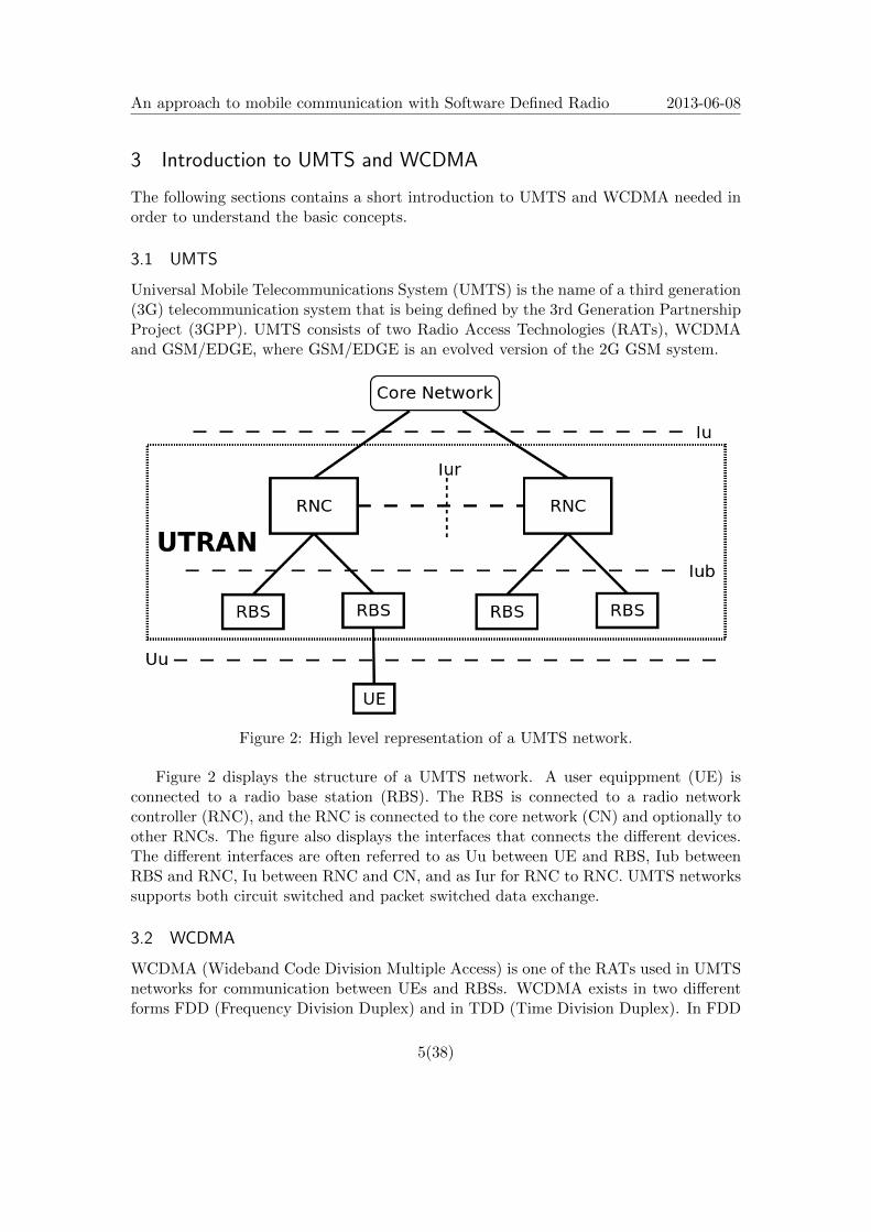
Figure 2: High level representation of a UMTS network.
Figure 2 displays the structure of a UMTS network. A user equippment (UE) isconnected to a radio base station (RBS). The RBS is connected to a radio networkcontroller (RNC), and the RNC is connected to the core network (CN) and optionally toother RNCs. The figure also displays the interfaces that connects the different devices.The different interfaces are often referred to as Uu between UE and RBS, Iub betweenRBS and RNC, Iu between RNC and CN, and as Iur for RNC to RNC. UMTS networkssupports both circuit switched and packet switched data exchange.
3.2 WCDMA
WCDMA (Wideband Code Division Multiple Access) is one of the RATs used in UMTSnetworks for communication between UEs and RBSs. WCDMA exists in two differentforms FDD (Frequency Division Duplex) and in TDD (Time Division Duplex). In FDD
5(38)
An approach to mobile communication with Software Defined Radio 2013-06-08
the uplink (UL) and downlink (DL) are separated by frequency, compared to TDD wherethe UL and DL are separated in the time domain. Throughout this document whenreferring to WCDMA it means WCDMA FDD, unless WCDMA TDD is specificallystated.
When sending signals through a shared physical medium, as the radio air interface,it is important to separate different signals or streams of data from each other. Thereexists numerous different techniques for doing this. CDMA, FDMA and TDMA areprobably some of the most common ways of dividing a shared medium between differentusers. As the name implies, WCDMA is based on CDMA, performed in wideband.
• FDMA - Frequency Division Multiple Access, divides the frequency usage betweenthe different users.
• TDMA - Time Division Multiple Access, the shared medium is divided in the timedomain between the different users.
• CDMA - Code Division Multiple Access, separates the different signals by encodingthem with special codes.
3.3 The WCDMA stack
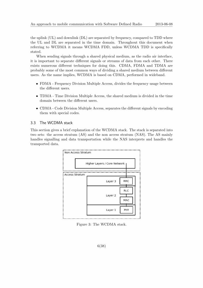
This section gives a brief explanation of the WCDMA stack. The stack is separated intotwo sets: the access stratum (AS) and the non access stratum (NAS). The AS mainlyhandles signalling and data transportation while the NAS interprets and handles thetransported data.
Figure 3: The WCDMA stack.
6(38)
An approach to mobile communication with Software Defined Radio 2013-06-08
3.3.1 RRC
The radio resource control (RRC) layer is responsible of establishing, maintaining andreleasing radio resource connections between the UE and the CN. The RRC controls thelower layers of the WCDMA stack.
3.3.2 RLC
The radio link control (RLC) layer provides transport services between RLC entities inthe UE and in the RNC. Three modes are supported: transparent, unacknowledged andacknowledged. In transparent mode the RLC passes packets directly without addingany extra header information. This requires that the packets being sent is of appropri-ate size. In unacknowledged mode the RLC passes packets onwards without ensuringdelivery. The data can be concatenate and padded in order to fit appropriate packetsize. Unacknowledged mode also contains some ciphering functionality. The acknowl-edged mode provides the same services as the unacknowledged mode with the additionof retransmission control, discarding of duplicated packets and in sequence delivery.
3.3.3 MAC
The medium access control (MAC) layer is responsible of mapping logical channels ontotransport channels. This mapping can change dynamically as the characteristics ofthe network or the user changes. The MAC layer is also responsible of reporting thebandwidth usage back to RRC.
3.3.4 PHY
PHY, the physical layer, is responsible mapping transport channels onto physical chan-nels and the transmission/reception of the physical channels over the air interface. Thephysical layer also deliver measurement reports back to the RRC.
3.4 Chips, slots and radio frames
In WCDMA each radio frame is 10 ms long. Each frame consists of 15 slots. Each slotconsists of 2560 chips. Giving a total of 38400 chips per frame or, in other words, a chiprate of 3.84 million chips per second. A chip is the smallest whole information carryingpart of the signal, although it is also possible and common to use fractions of chips,half-chip and quarter chips etc.
3.5 Modulation and complex signals
There exists three basic modulation techniques: frequency modulation (FM), amplitudemodulation, and phase modulation. WCDMA uses phase modulation and for somechannels a combination of phase and amplitude modulation. When dealing with phaseand amplitude modulation of a sinusoidal it is practical to represent the signal in the
7(38)
An approach to mobile communication with Software Defined Radio 2013-06-08
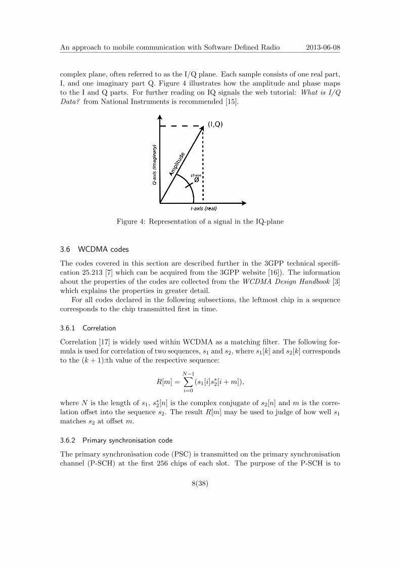
complex plane, often referred to as the I/Q plane. Each sample consists of one real part,I, and one imaginary part Q. Figure 4 illustrates how the amplitude and phase mapsto the I and Q parts. For further reading on IQ signals the web tutorial: What is I/QData? from National Instruments is recommended [15].
Figure 4: Representation of a signal in the IQ-plane
3.6 WCDMA codes
The codes covered in this section are described further in the 3GPP technical specifi-cation 25.213 [7] which can be acquired from the 3GPP website [16]). The informationabout the properties of the codes are collected from the WCDMA Design Handbook [3]which explains the properties in greater detail.
For all codes declared in the following subsections, the leftmost chip in a sequencecorresponds to the chip transmitted first in time.
3.6.1 Correlation
Correlation [17] is widely used within WCDMA as a matching filter. The following for-mula is used for correlation of two sequences, s1 and s2, where s1[k] and s2[k] correspondsto the (k + 1):th value of the respective sequence:
R[m] =N−1∑i=0
(s1[i]s∗2[i+m]),
where N is the length of s1, s∗2[n] is the complex conjugate of s2[n] and m is the corre-
lation offset into the sequence s2. The result R[m] may be used to judge of how well s1matches s2 at offset m.
3.6.2 Primary synchronisation code
The primary synchronisation code (PSC) is transmitted on the primary synchronisationchannel (P-SCH) at the first 256 chips of each slot. The purpose of the P-SCH is to
8(38)
An approach to mobile communication with Software Defined Radio 2013-06-08
ease the detection of the slots boundaries. According to [7] the PSC is constructed as aso-called generalised hierarchical Golay sequence and is constructed to have good auto-correlation properties, in short meaning that it will generate large peaks when perfectlyaligned and correlated against itself and almost no peak otherwise.
The PSC is defined as:
a = [x1, x2, x3, ..., x16]
= [1, 1, 1, 1, 1, 1,−1,−1, 1,−1, 1,−1, 1,−1,−1, 1]
PSC = (1 + j)[a, a, a,−a,−a, a,−a,−a, a, a, a,−a, a,−a, a, a]
3.6.3 Secondary synchronisation codes
The secondary synchronisation codes (SSC) are transmitted on the secondary synchro-nisation channel (S-SCH) at the first 256 chips of each slot. There exists 16 differentSSCs and they are used to create the 64 different S-SCH sequences defined by the 3GPP.The purpose of the S-SCH is to ease the detection of the frame boundaries and also toidentify what scrambling code group that a particular cell belongs to.
The SSCs {SSC1, SSC2, ..., SSC16} are constructed by combining a set of so-calledHadamard sequences with the sequence z defined as:
z = [b, b, b,−b, b, b,−b,−b, b,−b, b,−b,−b,−b,−b,−b]b = [x1, x2, x3, x4, x5, x6, x7, x8,−x9,−x10,−x11,−x12,−x13,−x14,−x15,−x16]
where {x1, x2, ..., x16} are the same as the {x1, x2, ..., x16} used in the definition of thePSC in the previous section.
SSCk = (1 + j)× [z(0)hk(0), z(1)hk(1), z(2)hk(2), z(3)hk(3), ..., z(255)hk(255)]
for 1 ≤ k ≤ 16 where hk(i) denotes the i:th symobol of the k:th Hadamard sequence andz(i), the i:th symbol of the z sequence.
The Hadamard sequences are obtained from the rows of a recursively created matrix,H8, defined as:
H0 = 1
Hj
[Hj−1 Hj−1
Hj−1 −Hj−1
], j > 0.
Finally hk is defined as hk = H8(16 ∗ (k− 1)), where H8(i) denotes the i:th row fromthe matrix H8.
3.6.4 Channelisation codes
The purpose of the channelisation codes are to spread and separate the different channelstransmitted from a RBS or a UE. One important property of channelisation codes areorthogonality, meaning that the sum of the position wise multiplication of two codes is
9(38)

An approach to mobile communication with Software Defined Radio 2013-06-08
equal to zero. This can be compared to an orthogonal system in a three-dimensionalspace where each dimension is completely independent of the others.
The formula below describes the relationship of the channelisation codes:
Ci = [Ci0, Ci1, Ci2, ..., Ci(N−1)],
Cj = [Cj0, Cj1, Cj2, ..., Cj(N−1)],
where Cin ε {+1,−1}, Cjn ε {+1,−1}, 0 ≤ n ≤ N − 1 and N defines the chip length ofeach code. The codes are orthogonal to each other if the following statement holds:
N−1∑n=0
CinCjn =
{0 i 6= jN i = j
.
The codes are created from a so-called orthogonal variable spreading factor (OVSF)three see Fig.5. The set of codes generated from the OVSF tree contains the sameorthogonal codes as codes generated using Hadamard or Walsh codes, the differencescomes from how they are indexed.
Figure 5: An Orthogonal Variable Spreading Factor Tree (OVSF-Tree). In the bit stringsdefining the OVSF codes a 0 represents +1 and a 1 represents -1.
3.6.5 Scrambling codes
The scrambling codes are used to separate the signals from multiple RBSs or UEs trans-mitting at the same frequency. The scrambling sequence is a pseudo random noisesequence which, by its own, appears as white noise. The properties of the scramblingcodes are, large impulse response when cross-correlated against itself and small whencorrelated against any of the other scrambling codes.
10(38)
An approach to mobile communication with Software Defined Radio 2013-06-08
The scrambling codes are divided into 512 sets each containing one primary andfifteen secondary codes. The codes are pseudo random noise sequences and built froma set of Gold sequences Zn, n = {0, 1, 2, ..., 218 − 2}, which are generated from two socalled m-sequences x and y. The x and y m-sequences and the Gold sequences Zn arerecursively defined as:
x(i+ 18) = (x(i+ 7) + x(i)) mod 2,
y(i+ 18) = (y(i+ 10) + y(i+ 7) + y(i+ 5) + y(i)) mod 2,
zn(i) = (x((i+ n) mod (218 − 1)) + y(i)) mod 2,
i = {0, 1, 2, ..., 218 − 20},n = {0, 1, 2, ..., 218 − 2},
with the following starting conditions for x and y as:
x(0) = 1,
x({1, 2, ..., 17}) = 0,
y({0, 1, 2, ..., 17}) = 1
The scrambling codes Sn are then finally defined as:
Sn(i) = Zn(i) + jZn((i+ 131072) mod (218 − 1)),
where i = {0, 1, ..., 38399} and n = 16 ∗m+ k where m defines the scrambling code setfrom 0..511 and k is equal to zero for primary scrambling codes and else in the rangefrom 1 to 15 for the secondary scrambling codes.
3.7 Modulation / demodulation
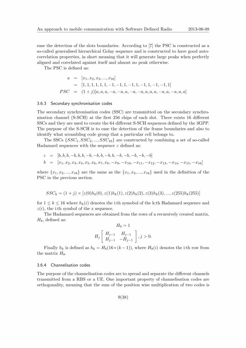
This section focuses on the transformation of the data from bits into chips, ready to betransmitted over the air interface. Figure 6 displays a simplified view of how bits fromone channel, are processed into chips.
Figure 6: The modulation pipeline from bits to antenna for a single channel
3.7.1 IQ modulation
In the process of IQ modulation, bits are turned into complex symbols. The symbolsare produced by dividing the two dimensional IQ space into regions (constellations) rep-resenting symbols, where each symbol represents a bit pattern. In QPSK (Quadrature
11(38)
An approach to mobile communication with Software Defined Radio 2013-06-08
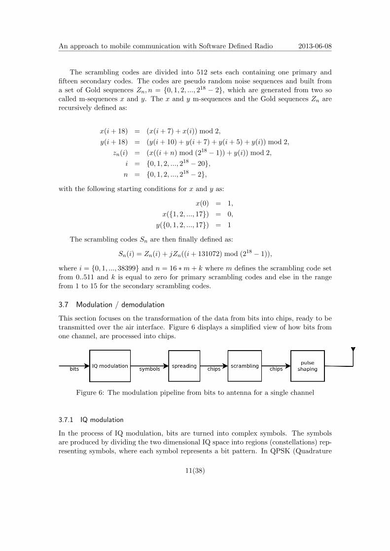
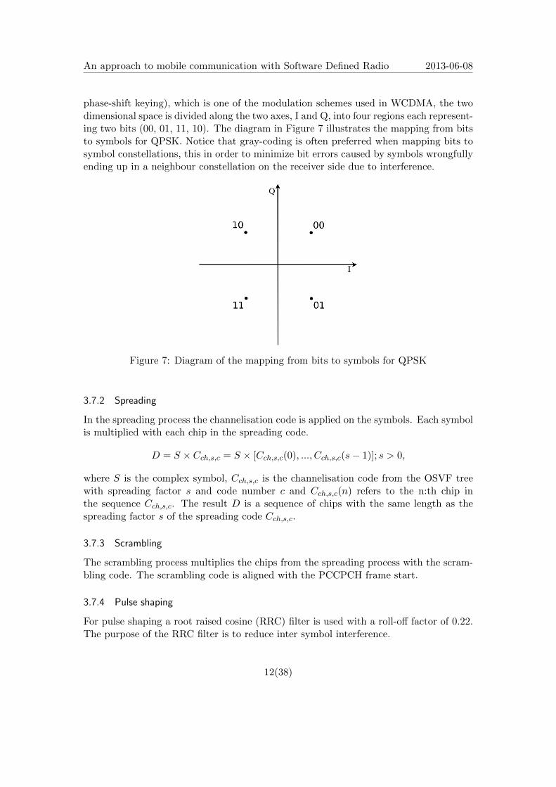
phase-shift keying), which is one of the modulation schemes used in WCDMA, the twodimensional space is divided along the two axes, I and Q, into four regions each represent-ing two bits (00, 01, 11, 10). The diagram in Figure 7 illustrates the mapping from bitsto symbols for QPSK. Notice that gray-coding is often preferred when mapping bits tosymbol constellations, this in order to minimize bit errors caused by symbols wrongfullyending up in a neighbour constellation on the receiver side due to interference.
Figure 7: Diagram of the mapping from bits to symbols for QPSK
3.7.2 Spreading
In the spreading process the channelisation code is applied on the symbols. Each symbolis multiplied with each chip in the spreading code.
D = S × Cch,s,c = S × [Cch,s,c(0), ..., Cch,s,c(s− 1)]; s > 0,
where S is the complex symbol, Cch,s,c is the channelisation code from the OSVF treewith spreading factor s and code number c and Cch,s,c(n) refers to the n:th chip inthe sequence Cch,s,c. The result D is a sequence of chips with the same length as thespreading factor s of the spreading code Cch,s,c.
3.7.3 Scrambling
The scrambling process multiplies the chips from the spreading process with the scram-bling code. The scrambling code is aligned with the PCCPCH frame start.
3.7.4 Pulse shaping
For pulse shaping a root raised cosine (RRC) filter is used with a roll-off factor of 0.22.The purpose of the RRC filter is to reduce inter symbol interference.
12(38)
An approach to mobile communication with Software Defined Radio 2013-06-08
3.8 Channels
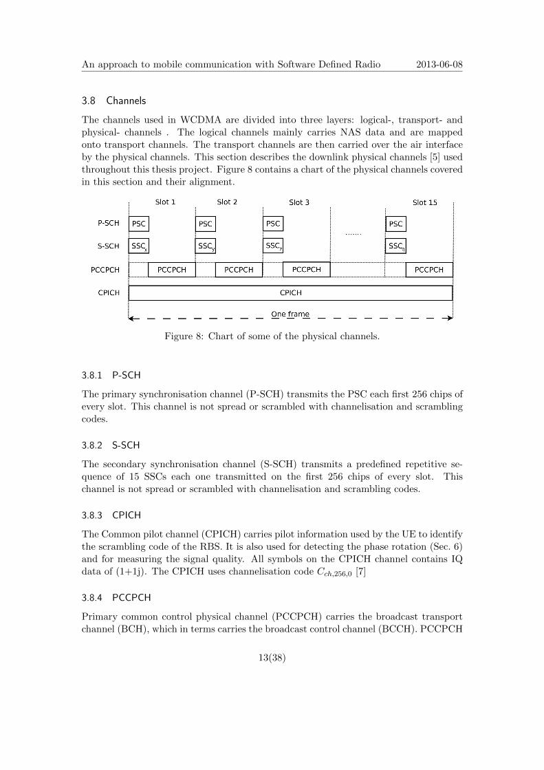
The channels used in WCDMA are divided into three layers: logical-, transport- andphysical- channels . The logical channels mainly carries NAS data and are mappedonto transport channels. The transport channels are then carried over the air interfaceby the physical channels. This section describes the downlink physical channels [5] usedthroughout this thesis project. Figure 8 contains a chart of the physical channels coveredin this section and their alignment.
Figure 8: Chart of some of the physical channels.
3.8.1 P-SCH
The primary synchronisation channel (P-SCH) transmits the PSC each first 256 chips ofevery slot. This channel is not spread or scrambled with channelisation and scramblingcodes.
3.8.2 S-SCH
The secondary synchronisation channel (S-SCH) transmits a predefined repetitive se-quence of 15 SSCs each one transmitted on the first 256 chips of every slot. Thischannel is not spread or scrambled with channelisation and scrambling codes.
3.8.3 CPICH
The Common pilot channel (CPICH) carries pilot information used by the UE to identifythe scrambling code of the RBS. It is also used for detecting the phase rotation (Sec. 6)and for measuring the signal quality. All symbols on the CPICH channel contains IQdata of (1+1j). The CPICH uses channelisation code Cch,256,0 [7]
3.8.4 PCCPCH
Primary common control physical channel (PCCPCH) carries the broadcast transportchannel (BCH), which in terms carries the broadcast control channel (BCCH). PCCPCH
13(38)
An approach to mobile communication with Software Defined Radio 2013-06-08
uses QPSK modulation and channelisation code Cch,256,1 [7]. No information is trans-mitted the first 256 chips of every slot on PCCPCH.
14(38)
An approach to mobile communication with Software Defined Radio 2013-06-08
4 RSSI scan
A RSSI scan (received signal strength indicator scan) is performed by measuring theenergy on a set of frequencies. Frequencies with higher energy levels are potentiallybetter candidates for containing a WCDMA cell. The RSSI measurements done in thisthesis is done by calculating the squared magnitude of the received IQ samples.
15(38)
An approach to mobile communication with Software Defined Radio 2013-06-08
5 Synchronisation
This section describes the synchronisation process, derived from the cell search procedurein [8]. The process is divided into three parts: slot synchronisation, frame synchronisa-tion and scrambling code identification. It is however possible to identify the scramblingcode and find slot and frame synchronisation without the first two steps but it makes theprocess much more complex in terms of computational complexity. Correlating all 512primary scrambling codes against the received signal, measuring which one producingthe largest response on every chip over at least an entire frame would simply be tootime consuming. The first steps in the synchronisation procedure eliminates the set ofpossible scrambling codes down to eight and also detects the frame boundaries so thateach possible scrambling code only needs to be correlated using one correlation offsetthat matches a frame boundary.
5.1 Slot synchronisation
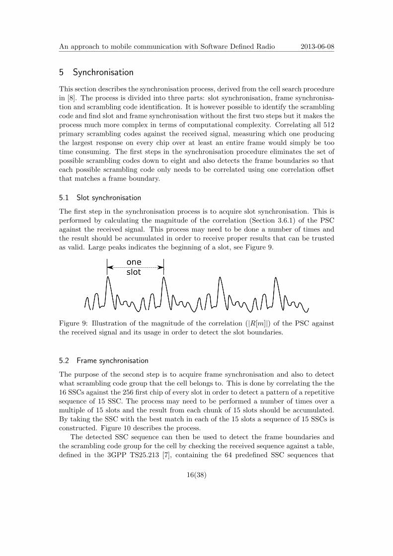
The first step in the synchronisation process is to acquire slot synchronisation. This isperformed by calculating the magnitude of the correlation (Section 3.6.1) of the PSCagainst the received signal. This process may need to be done a number of times andthe result should be accumulated in order to receive proper results that can be trustedas valid. Large peaks indicates the beginning of a slot, see Figure 9.
Figure 9: Illustration of the magnitude of the correlation (|R[m]|) of the PSC againstthe received signal and its usage in order to detect the slot boundaries.
5.2 Frame synchronisation
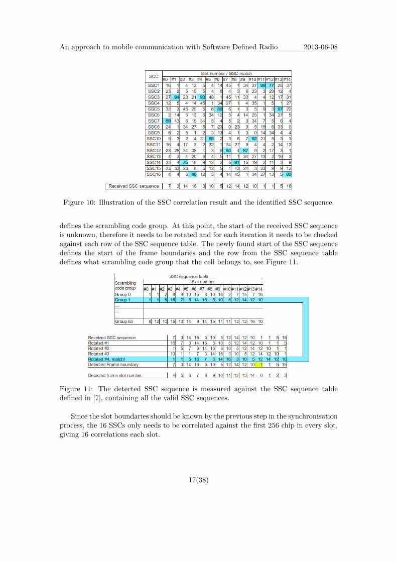
The purpose of the second step is to acquire frame synchronisation and also to detectwhat scrambling code group that the cell belongs to. This is done by correlating the the16 SSCs against the 256 first chip of every slot in order to detect a pattern of a repetitivesequence of 15 SSC. The process may need to be performed a number of times over amultiple of 15 slots and the result from each chunk of 15 slots should be accumulated.By taking the SSC with the best match in each of the 15 slots a sequence of 15 SSCs isconstructed. Figure 10 describes the process.
The detected SSC sequence can then be used to detect the frame boundaries andthe scrambling code group for the cell by checking the received sequence against a table,defined in the 3GPP TS25.213 [7], containing the 64 predefined SSC sequences that
16(38)
An approach to mobile communication with Software Defined Radio 2013-06-08
Figure 10: Illustration of the SSC correlation result and the identified SSC sequence.
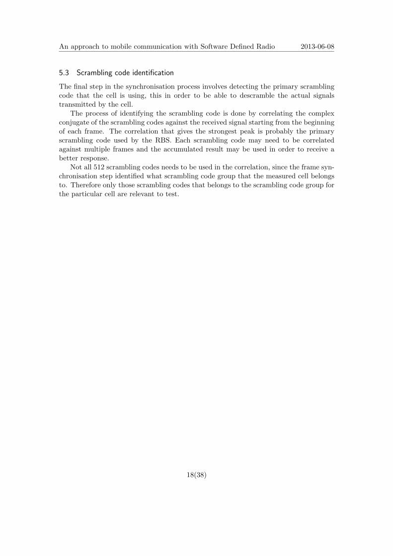
defines the scrambling code group. At this point, the start of the received SSC sequenceis unknown, therefore it needs to be rotated and for each iteration it needs to be checkedagainst each row of the SSC sequence table. The newly found start of the SSC sequencedefines the start of the frame boundaries and the row from the SSC sequence tabledefines what scrambling code group that the cell belongs to, see Figure 11.
Figure 11: The detected SSC sequence is measured against the SSC sequence tabledefined in [7], containing all the valid SSC sequences.
Since the slot boundaries should be known by the previous step in the synchronisationprocess, the 16 SSCs only needs to be correlated against the first 256 chip in every slot,giving 16 correlations each slot.
17(38)
An approach to mobile communication with Software Defined Radio 2013-06-08
5.3 Scrambling code identification
The final step in the synchronisation process involves detecting the primary scramblingcode that the cell is using, this in order to be able to descramble the actual signalstransmitted by the cell.
The process of identifying the scrambling code is done by correlating the complexconjugate of the scrambling codes against the received signal starting from the beginningof each frame. The correlation that gives the strongest peak is probably the primaryscrambling code used by the RBS. Each scrambling code may need to be correlatedagainst multiple frames and the accumulated result may be used in order to receive abetter response.
Not all 512 scrambling codes needs to be used in the correlation, since the frame syn-chronisation step identified what scrambling code group that the measured cell belongsto. Therefore only those scrambling codes that belongs to the scrambling code group forthe particular cell are relevant to test.
18(38)
An approach to mobile communication with Software Defined Radio 2013-06-08
6 Phase rotation
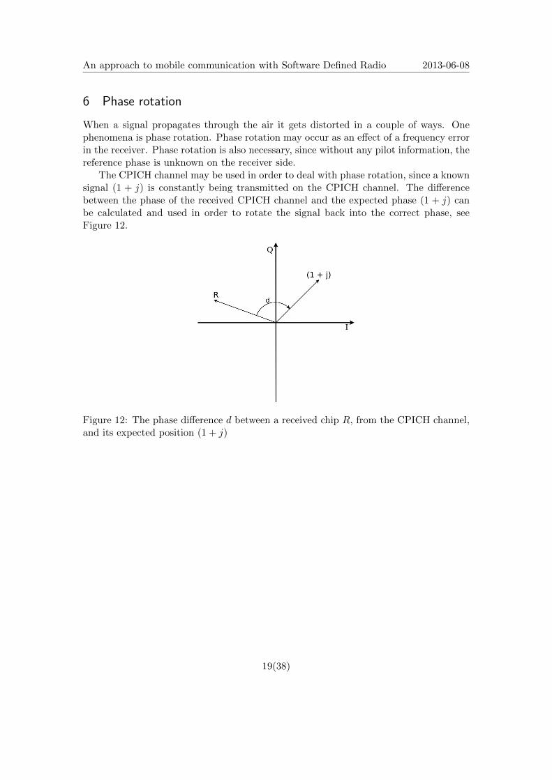
When a signal propagates through the air it gets distorted in a couple of ways. Onephenomena is phase rotation. Phase rotation may occur as an effect of a frequency errorin the receiver. Phase rotation is also necessary, since without any pilot information, thereference phase is unknown on the receiver side.
The CPICH channel may be used in order to deal with phase rotation, since a knownsignal (1 + j) is constantly being transmitted on the CPICH channel. The differencebetween the phase of the received CPICH channel and the expected phase (1 + j) canbe calculated and used in order to rotate the signal back into the correct phase, seeFigure 12.
Figure 12: The phase difference d between a received chip R, from the CPICH channel,and its expected position (1 + j)
19(38)
An approach to mobile communication with Software Defined Radio 2013-06-08
7 From signal to bits
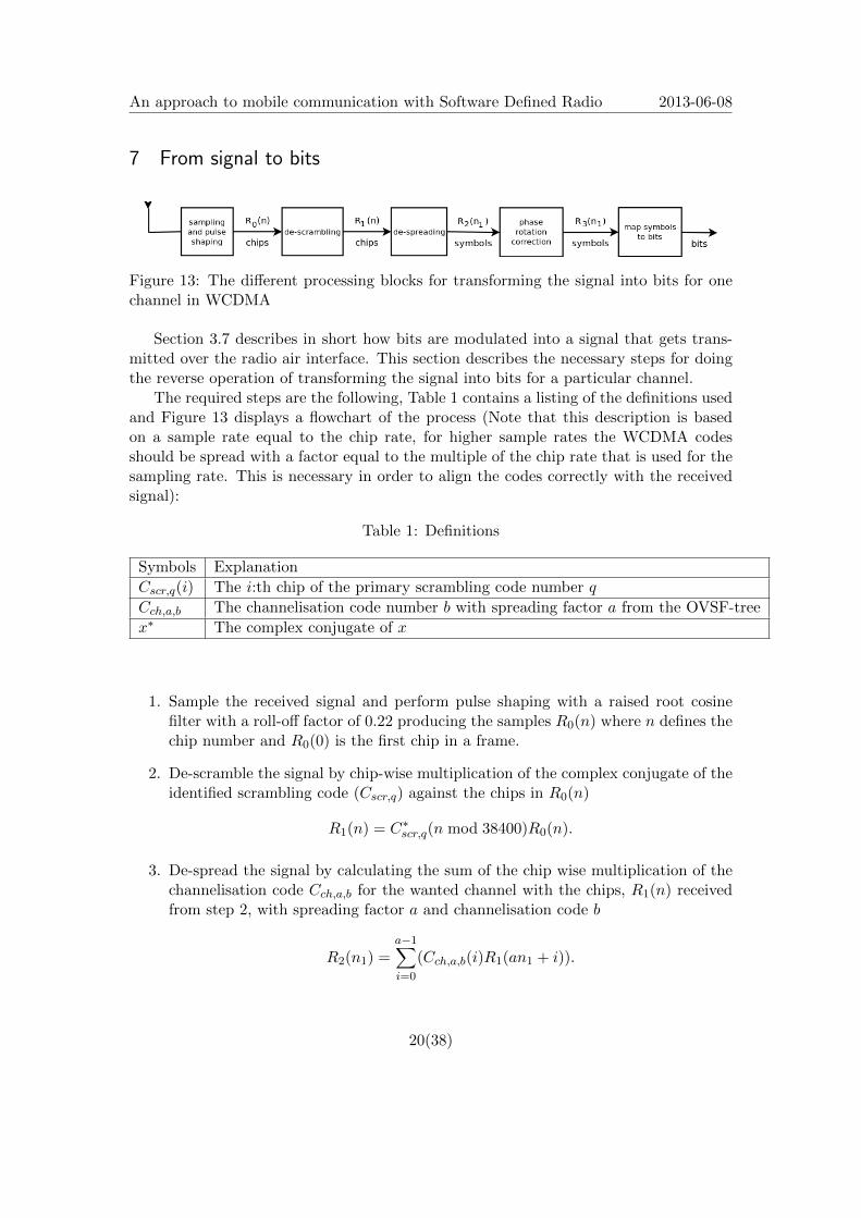
Figure 13: The different processing blocks for transforming the signal into bits for onechannel in WCDMA
Section 3.7 describes in short how bits are modulated into a signal that gets trans-mitted over the radio air interface. This section describes the necessary steps for doingthe reverse operation of transforming the signal into bits for a particular channel.
The required steps are the following, Table 1 contains a listing of the definitions usedand Figure 13 displays a flowchart of the process (Note that this description is basedon a sample rate equal to the chip rate, for higher sample rates the WCDMA codesshould be spread with a factor equal to the multiple of the chip rate that is used for thesampling rate. This is necessary in order to align the codes correctly with the receivedsignal):
Table 1: Definitions
Symbols Explanation
Cscr,q(i) The i:th chip of the primary scrambling code number q
Cch,a,b The channelisation code number b with spreading factor a from the OVSF-tree
x∗ The complex conjugate of x
1. Sample the received signal and perform pulse shaping with a raised root cosinefilter with a roll-off factor of 0.22 producing the samples R0(n) where n defines thechip number and R0(0) is the first chip in a frame.
2. De-scramble the signal by chip-wise multiplication of the complex conjugate of theidentified scrambling code (Cscr,q) against the chips in R0(n)
R1(n) = C∗scr,q(n mod 38400)R0(n).
3. De-spread the signal by calculating the sum of the chip wise multiplication of thechannelisation code Cch,a,b for the wanted channel with the chips, R1(n) receivedfrom step 2, with spreading factor a and channelisation code b
R2(n1) =a−1∑i=0
(Cch,a,b(i)R1(an1 + i)).
20(38)
An approach to mobile communication with Software Defined Radio 2013-06-08
4. At this step it would be possible to measure the phase difference for the CPICH(see Section 6). If phase rotation has occurred the signal needs to be rotated backin order to decode the other channels. Taking the symbols in R2(n1) as inputand correct the phase against the CPICH producing the phase corrected symbols,R3(n1) as output.
5. Map the chips R3(n1) from symbols to bits. Different channels may use differentmodulation techniques. For PCCPCH which carries the BCH QPSK is used (seeSection 3.7.1).
6. Done, a sequence of bits can now be obtained for a specific channel.
21(38)
An approach to mobile communication with Software Defined Radio 2013-06-08
8 Decoding the broadcast channel
The BCCH is the logical channel containing the broadcast messages transmitted by theRBS. The BCCH is mapped onto the transport blocks (TrBlk) on the BCH transportchannel and the BCH is mapped onto the PCCPCH that is transmitted over the air.
This section describes the mapping from BCH to PCCPCH and how to perform thereverse operation. The process is derived from 3GPP TS 25.212 [6] (Section 4 Multi-plexing, channel coding and interleaving ) and TS 25.302 [18] (Annex A (normative):Description of Transport Formats) which describes the process in general for all channels.
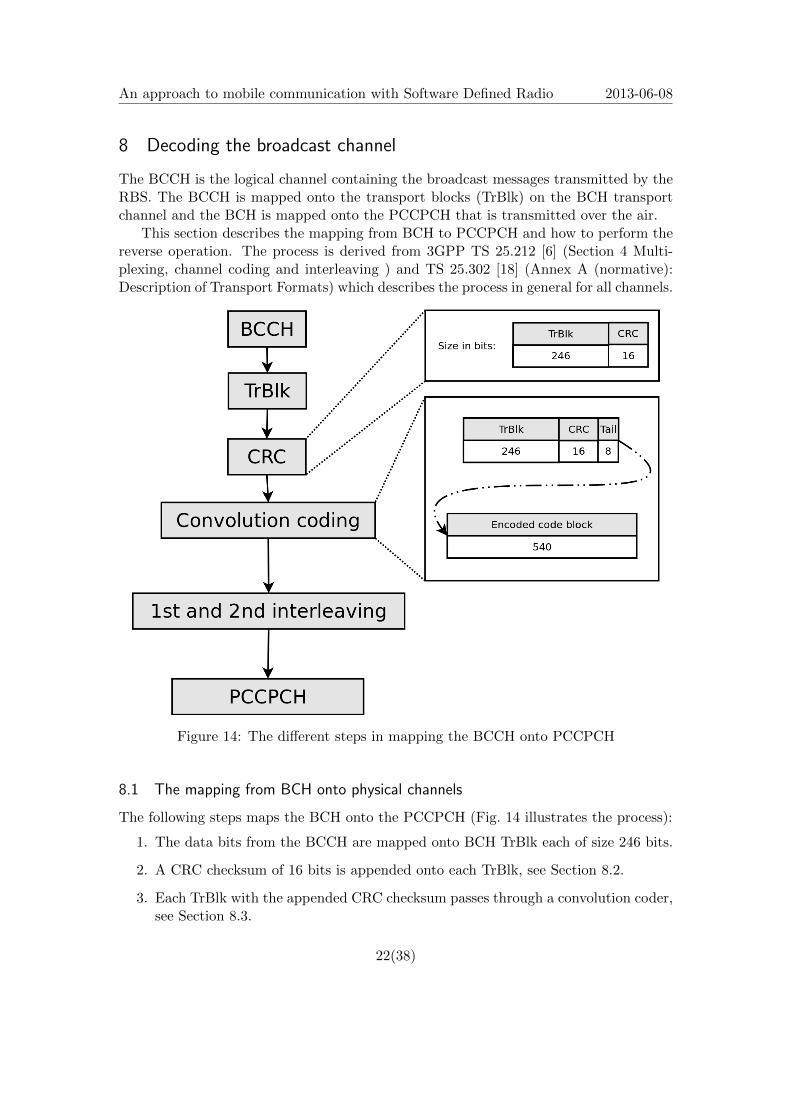
Figure 14: The different steps in mapping the BCCH onto PCCPCH
8.1 The mapping from BCH onto physical channels
The following steps maps the BCH onto the PCCPCH (Fig. 14 illustrates the process):
1. The data bits from the BCCH are mapped onto BCH TrBlk each of size 246 bits.
2. A CRC checksum of 16 bits is appended onto each TrBlk, see Section 8.2.
3. Each TrBlk with the appended CRC checksum passes through a convolution coder,see Section 8.3.
22(38)

An approach to mobile communication with Software Defined Radio 2013-06-08
4. Bit interleaving.
5. Data is passed onwards to the PCCPCH.
8.2 Cyclic redundancy check
The purpose of the Cyclic redundancy check (CRC) is to create a set of bits which can beused on the receiver side to verify that the received bits are correct, although it shouldbe noticed that there is a slight chance that bit errors may be introduced in both theCRC bits and the CRC encoded data, this could make the CRC bit check pass on thereceiver side even though the received bits contains errors. There is also the case ofwhen the CRC coded data is intact but bit errors have been introduced in the CRC bits,in that case there is no way of detecting at the receiver side what actually happened.Instead the CRC coded data gets discarded as invalid.
The CRC calculator takes TrBlks as input, calculates and outputs the CRC bit stringand finally attaches it at the end of the TrBlk. Figure 15 displays a scheme of the 16-bitCRC calculator, with the generator polynomial of D16 + D12 + D5 + 1, that is usedto calculate the CRC bits for BCH. The bits from the transport block is inserted intothe CRC calculator. During TrBlk insertion the output bits are ignored. The CRCcalculator is cleared between each TrBlk by inserting zero bits. The output generatedwhile clearing the CRC calculator is the actual CRC bits that are appended to the TrBlk.
Figure 15: A scheme of the 16-bit CRC calculator used in WCDMA
8.3 Convolutional coding
WCDMA uses two different types of forward error correcting codes: Convolution codingand Turbo coding. The purpose of the error correcting codes are to correct bit errors thatmay have been introduced when data was transmitted over the air interface. For the BCHhalf-rate (1/2) convolution coding is applied, meaning that one input bit generates twooutput bits. Figure 16 contains a chart of the 1/2 convolution coder used in WCDMA.The encoding machine is a state machine with 2k number of states where k is the numberof memory registers holding the current state of the machine (as seen in Fig.16).
Code blocks are delivered as input to the convolution coding machine one at a timein sequence. Each code block consists of a TrBlk with the appended CRC bits and eighttail bits of zeros. The purpose of the tail bits are to clear the state of the convolutioncoding machine between each code block.
23(38)
An approach to mobile communication with Software Defined Radio 2013-06-08
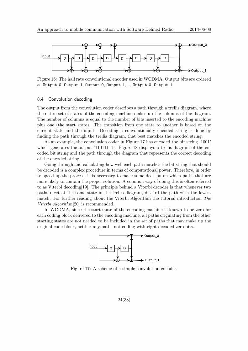
Figure 16: The half rate convolutional encoder used in WCDMA. Output bits are orderedas Output 0, Output 1, Output 0, Output 1,..., Output 0, Output 1
8.4 Convolution decoding
The output from the convolution coder describes a path through a trellis diagram, wherethe entire set of states of the encoding machine makes up the columns of the diagram.The number of columns is equal to the number of bits inserted to the encoding machineplus one (the start state). The transition from one state to another is based on thecurrent state and the input. Decoding a convolutionally encoded string is done byfinding the path through the trellis diagram, that best matches the encoded string.
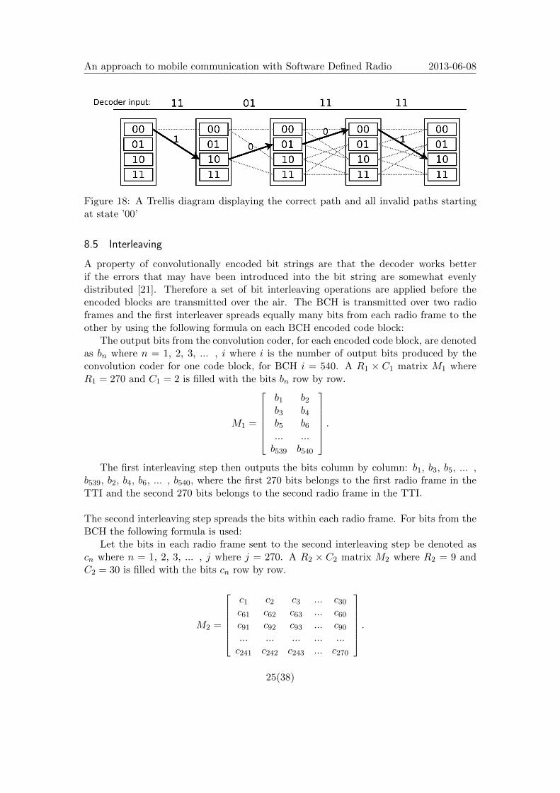
As an example, the convolution coder in Figure 17 has encoded the bit string ’1001’which generates the output ’11011111’. Figure 18 displays a trellis diagram of the en-coded bit string and the path through the diagram that represents the correct decodingof the encoded string.
Going through and calculating how well each path matches the bit string that shouldbe decoded is a complex procedure in terms of computational power. Therefore, in orderto speed up the process, it is necessary to make some decision on which paths that aremore likely to contain the proper solution. A common way of doing this is often referredto as Viterbi decoding[19]. The principle behind a Viterbi decoder is that whenever twopaths meet at the same state in the trellis diagram, discard the path with the lowestmatch. For further reading about the Viterbi Algorithm the tutorial introduction TheViterbi Algorithm[20] is recommended.
In WCDMA, since the start state of the encoding machine is known to be zero foreach coding block delivered to the encoding machine, all paths originating from the otherstarting states are not needed to be included in the set of paths that may make up theoriginal code block, neither any paths not ending with eight decoded zero bits.
Figure 17: A scheme of a simple convolution encoder.
24(38)
An approach to mobile communication with Software Defined Radio 2013-06-08
Figure 18: A Trellis diagram displaying the correct path and all invalid paths startingat state ’00’
8.5 Interleaving
A property of convolutionally encoded bit strings are that the decoder works betterif the errors that may have been introduced into the bit string are somewhat evenlydistributed [21]. Therefore a set of bit interleaving operations are applied before theencoded blocks are transmitted over the air. The BCH is transmitted over two radioframes and the first interleaver spreads equally many bits from each radio frame to theother by using the following formula on each BCH encoded code block:
The output bits from the convolution coder, for each encoded code block, are denotedas bn where n = 1, 2, 3, ... , i where i is the number of output bits produced by theconvolution coder for one code block, for BCH i = 540. A R1 × C1 matrix M1 whereR1 = 270 and C1 = 2 is filled with the bits bn row by row.
M1 =
b1 b2b3 b4b5 b6... ...b539 b540
.
The first interleaving step then outputs the bits column by column: b1, b3, b5, ... ,b539, b2, b4, b6, ... , b540, where the first 270 bits belongs to the first radio frame in theTTI and the second 270 bits belongs to the second radio frame in the TTI.
The second interleaving step spreads the bits within each radio frame. For bits from theBCH the following formula is used:
Let the bits in each radio frame sent to the second interleaving step be denoted ascn where n = 1, 2, 3, ... , j where j = 270. A R2 × C2 matrix M2 where R2 = 9 andC2 = 30 is filled with the bits cn row by row.
M2 =
c1 c2 c3 ... c30c61 c62 c63 ... c60c91 c92 c93 ... c90... ... ... ... ...c241 c242 c243 ... c270
.
25(38)
An approach to mobile communication with Software Defined Radio 2013-06-08
A new matrix M2p is then defined as an inter column permutation of the matrix M2
according to the following pattern:M2p = [A0, A20, A10, A5, A15, A25, A3, A13, A23, A8, A18, A28, A1, A11, A21, A6, A16,A26, A4, A14, A24, A19, A9, A29, A12, A2, A7, A22, A27, A17],where A0,1,2,...,29 are the columns of matrix M2 from left to right.
The output bits from the second interleaving step are then read out column bycolumn from the matrix M2p.
8.6 The BCH data bits
Finally when the entire process of reading bits on the PCCPCH (Section 7) and theprocess of decoding the PCCPCH bits turning them into BCH bits (Section 8), theBCH data bits are revealed.
The BCH data bits carries the broadcast messages and the System Frame Number(SFN) of the current cell. The SFN is the first 12 bits of every BCH TrBlk and the restof the data bits carries the BCCH messages. The BCCH messages basically consists ofa set of different data blocks. The Master Information Block (MIB) describes when theother System Information Blocks (SIBs) are scheduled. The SIBs contains the actualinformation about the current cell.
26(38)
An approach to mobile communication with Software Defined Radio 2013-06-08
9 Implementation
This section covers the implementation, the design of the software and implementationspecific issues.
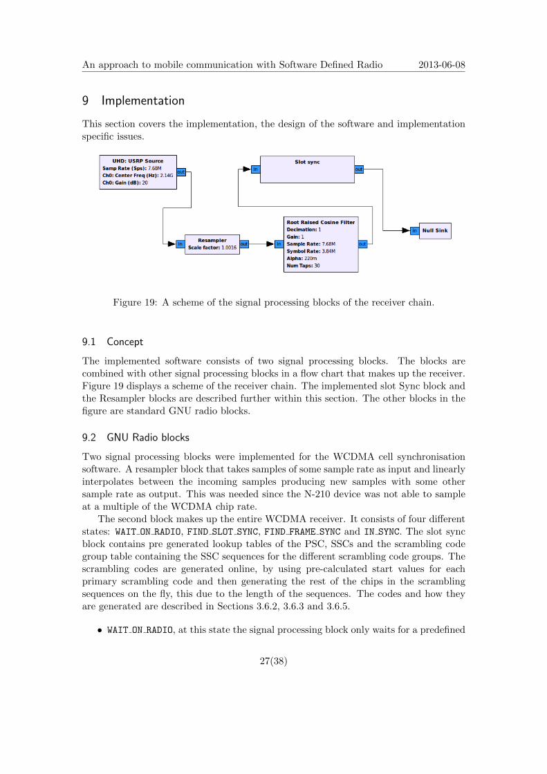
Figure 19: A scheme of the signal processing blocks of the receiver chain.
9.1 Concept
The implemented software consists of two signal processing blocks. The blocks arecombined with other signal processing blocks in a flow chart that makes up the receiver.Figure 19 displays a scheme of the receiver chain. The implemented slot Sync block andthe Resampler blocks are described further within this section. The other blocks in thefigure are standard GNU radio blocks.
9.2 GNU Radio blocks
Two signal processing blocks were implemented for the WCDMA cell synchronisationsoftware. A resampler block that takes samples of some sample rate as input and linearlyinterpolates between the incoming samples producing new samples with some othersample rate as output. This was needed since the N-210 device was not able to sampleat a multiple of the WCDMA chip rate.
The second block makes up the entire WCDMA receiver. It consists of four differentstates: WAIT ON RADIO, FIND SLOT SYNC, FIND FRAME SYNC and IN SYNC. The slot syncblock contains pre generated lookup tables of the PSC, SSCs and the scrambling codegroup table containing the SSC sequences for the different scrambling code groups. Thescrambling codes are generated online, by using pre-calculated start values for eachprimary scrambling code and then generating the rest of the chips in the scramblingsequences on the fly, this due to the length of the sequences. The codes and how theyare generated are described in Sections 3.6.2, 3.6.3 and 3.6.5.
• WAIT ON RADIO, at this state the signal processing block only waits for a predefined
27(38)

An approach to mobile communication with Software Defined Radio 2013-06-08
number of samples in order to make sure that the radio has become stable. Whendone, it changes state into FIND SLOT SYNC.
• FIND SLOT SYNC, at this state the signal processing block searches for the slotboundaries by correlating the PSC against the received signal in order to detect slotboundaries (Section 5.1). To improve the slot boundary detection, the correlationis performed for the duration of 3 frames and the result is accumulated in order toimprove the correlation peaks.
This is performed by, for each new sample that is arriving to the signal processingblock, calculating the sum of the chip wise multiplication of the PSC and the latestreceived samples. The result is accumulated in a buffer, BsbAcc, with length equalto the number of samples per slot l, in this case 5120. The result is stored atposition isample, where i is the current sample number. After 3× 15× l number ofsamples (three frames) the index isBound of the highest accumulated value in thebuffer BsbAcc is calculated. The slot boundaries can now be considered to starton each sample where the following condition is met, ((s + 511) mod l) = isBound
where s is the sample number. The addition of 511 comes from fact that the indexisBound is placed at the end of the PSC correlation, and each new slot starts at thebeginning of the PSC.
• FIND FRAME SYNC, at this state the signal processing block tries to detect the frameboundaries and tries to identify the scrambling code group (Section 5.2). On suc-cess it switches state into IN SYNC and in case of failure to detect frame boundariesor scrambling code group it goes back to state WAIT ON RADIO, to try the same pro-cedure again.
At the start of each slot 512 samples are stored away in a buffer Bs−sch, capturingthe S-SCH. The sixteen SSCs are then correlated against the buffer Bs−sch at offsetzero in order to decide which SSC with the best match in each slot. The resultis accumulated over seven frames before deciding which SSC sequence the cell isusing. The SSC sequence is then checked against a table containing the valid SSCsequences for each scrambling code group.
• IN SYNC, when in this state the slot- and frame- boundaries and the scramblingcode group have been successfully detected. In this state the signal processingblock starts to identify the primary scrambling code for the cell, as described inSection 5.3. Once detected it starts receiving the PCCPCH bits (see Section 7).Meanwhile in this state, since the samples delivered to the block may drift in timewith respect to how they are transmitted from the RBS, some simple mechanism isneeded in order to keep slot and frame synchronisation. This is done by correlatingthe PSC around the detected slot boundaries in order to detect if the chips aredrifting in time. If this occurs it is corrected by inserting or removing extra chips.Received PCCPCH frames are stored away in an array for offline processing, sincethe decoding of the BCH is too time consuming to be performed in real time bysoftware running on a standard computer at the time of the implementation.
28(38)
An approach to mobile communication with Software Defined Radio 2013-06-08
9.3 Fitting it all together
Figure 19 shows the resampler block and the cell sync block together with the rest of thereceiver chain. A python script launches the application and sets the frequency. It thenpolls the cell sync block for information about the number of synchronisation tries, andif it has finished reading the PCCPCH frames. If a defined number of synchronisationtries has been done without successfully reading the PCCPCH frames the applicationterminates. When all PCCPCH frames has been successfully read by the slot sync block,the receiver chain is stopped and the decoding of the BCH is handled by the pythonscript as explained in Section 8.
29(38)
An approach to mobile communication with Software Defined Radio 2013-06-08
10 Results
10.1 Receiver performance
The RSSI scan performance were measured in a lab environmet, scanning through thefrequency range from 2.126 GHz to 2.158 GHz on a 200 kHz raster with one cell locatedat 2.14 GHz. With a cell power of −90 dBm / 3.84 MHz the frequency containing thecell is placed around the first quartile in the frequency ranking list from the RSSI scan.Raising the cell power to −75 dBm / 3.84 MHz places the cell frequency near the top ofthe ranking list.
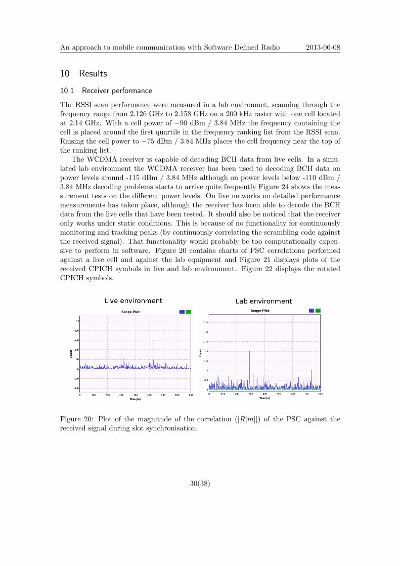
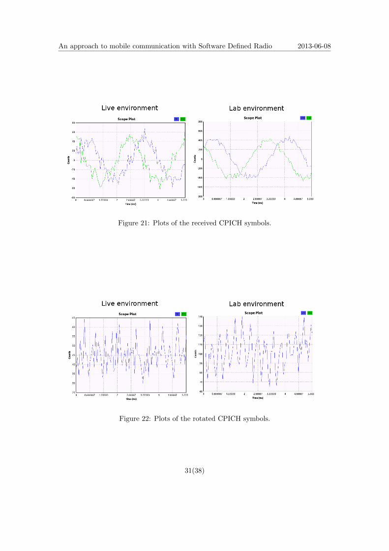
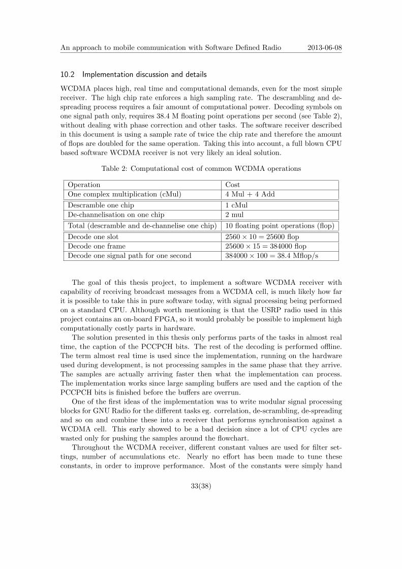
The WCDMA receiver is capable of decoding BCH data from live cells. In a simu-lated lab environment the WCDMA receiver has been used to decoding BCH data onpower levels around -115 dBm / 3.84 MHz although on power levels below -110 dBm /3.84 MHz decoding problems starts to arrive quite frequently Figure 24 shows the mea-surement tests on the different power levels. On live networks no detailed performancemeasurements has taken place, although the receiver has been able to decode the BCHdata from the live cells that have been tested. It should also be noticed that the receiveronly works under static conditions. This is because of no functionality for continuouslymonitoring and tracking peaks (by continuously correlating the scrambling code againstthe received signal). That functionality would probably be too computationally expen-sive to perform in software. Figure 20 contains charts of PSC correlations performedagainst a live cell and against the lab equipment and Figure 21 displays plots of thereceived CPICH symbols in live and lab environment. Figure 22 displays the rotatedCPICH symbols.
Figure 20: Plot of the magnitude of the correlation (|R[m]|) of the PSC against thereceived signal during slot synchronisation.
30(38)
An approach to mobile communication with Software Defined Radio 2013-06-08
Figure 21: Plots of the received CPICH symbols.
Figure 22: Plots of the rotated CPICH symbols.
31(38)

An approach to mobile communication with Software Defined Radio 2013-06-08
During the development of the receiver, the Raised Root Cosine (RRC) filter unin-tentionally was left unconfigured, resulting in the filter having none or minimum impact.Configuring the RRC filter resulted in a great performance boost. From having troublewith reading the BCH and synchronising against cells with power levels below -80 dBm/ 3.84 MHz to having no problem at power levels below -100 dBm / 3.84 MHz. Figure 23and 24 shows performance graphs of the receiver, before and after the RRC filter setup.The performance data were collected by examining the results from six consecutive testruns of the receiver software on each power level.
Figure 23: Performance graph of the receiver for different power levels, before RRC filtersetup.
Figure 24: Performance graph of the receiver for different power levels, after the RRCfilter setup.
32(38)
An approach to mobile communication with Software Defined Radio 2013-06-08
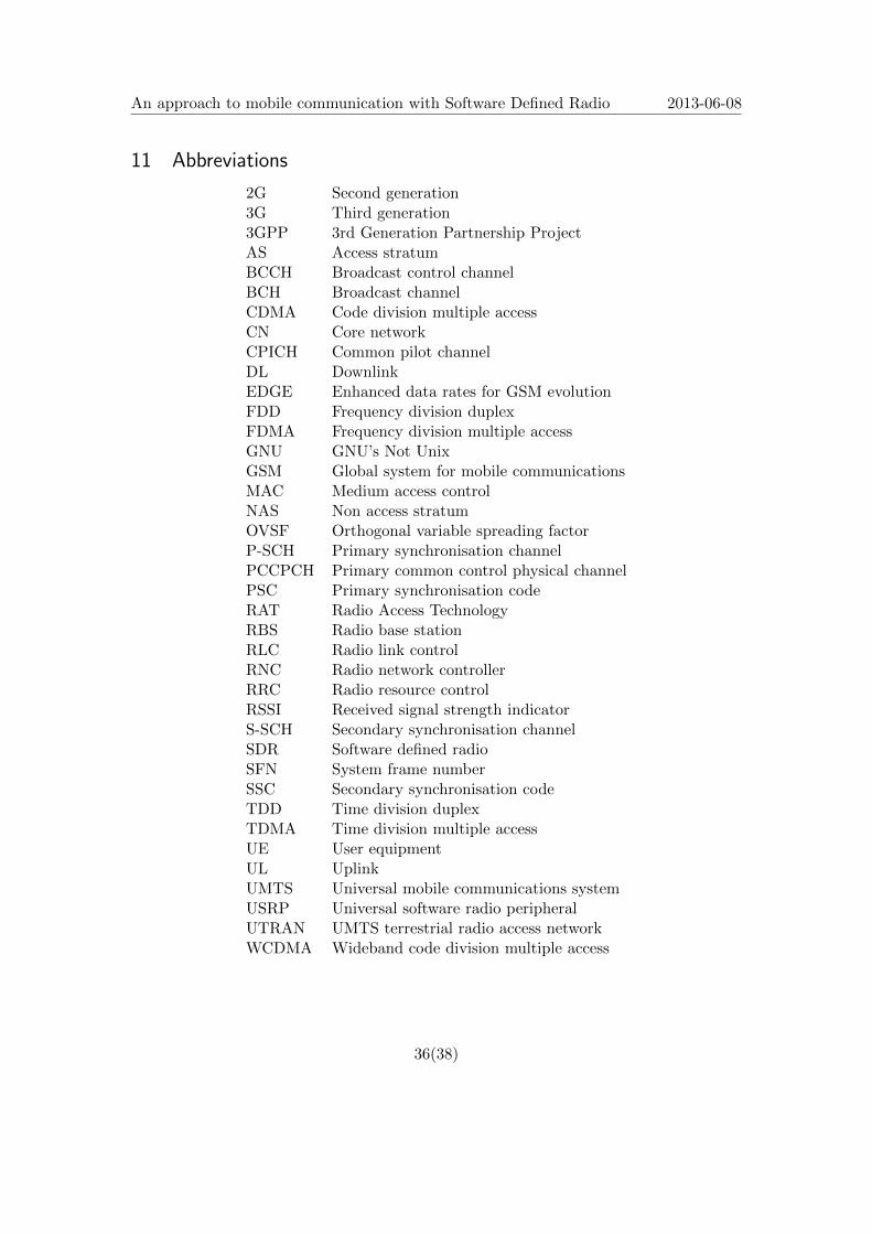
10.2 Implementation discussion and details
WCDMA places high, real time and computational demands, even for the most simplereceiver. The high chip rate enforces a high sampling rate. The descrambling and de-spreading process requires a fair amount of computational power. Decoding symbols onone signal path only, requires 38.4 M floating point operations per second (see Table 2),without dealing with phase correction and other tasks. The software receiver describedin this document is using a sample rate of twice the chip rate and therefore the amountof flops are doubled for the same operation. Taking this into account, a full blown CPUbased software WCDMA receiver is not very likely an ideal solution.
Table 2: Computational cost of common WCDMA operations
Operation Cost
One complex multiplication (cMul) 4 Mul + 4 Add
Descramble one chip 1 cMul
De-channelisation on one chip 2 mul
Total (descramble and de-channelise one chip) 10 floating point operations (flop)
Decode one slot 2560× 10 = 25600 flop
Decode one frame 25600× 15 = 384000 flop
Decode one signal path for one second 384000× 100 = 38.4 Mflop/s
The goal of this thesis project, to implement a software WCDMA receiver withcapability of receiving broadcast messages from a WCDMA cell, is much likely how farit is possible to take this in pure software today, with signal processing being performedon a standard CPU. Although worth mentioning is that the USRP radio used in thisproject contains an on-board FPGA, so it would probably be possible to implement highcomputationally costly parts in hardware.
The solution presented in this thesis only performs parts of the tasks in almost realtime, the caption of the PCCPCH bits. The rest of the decoding is performed offline.The term almost real time is used since the implementation, running on the hardwareused during development, is not processing samples in the same phase that they arrive.The samples are actually arriving faster then what the implementation can process.The implementation works since large sampling buffers are used and the caption of thePCCPCH bits is finished before the buffers are overrun.
One of the first ideas of the implementation was to write modular signal processingblocks for GNU Radio for the different tasks eg. correlation, de-scrambling, de-spreadingand so on and combine these into a receiver that performs synchronisation against aWCDMA cell. This early showed to be a bad decision since a lot of CPU cycles arewasted only for pushing the samples around the flowchart.
Throughout the WCDMA receiver, different constant values are used for filter set-tings, number of accumulations etc. Nearly no effort has been made to tune theseconstants, in order to improve performance. Most of the constants were simply hand
33(38)

An approach to mobile communication with Software Defined Radio 2013-06-08
picked during the implementation phase, so there is probably some optimisations thatcan be done by simply tweaking the different constants.
10.3 Conclusions and discussion
Traditional radio hardware development is an expensive and cumbersome process, espe-cially when compared to writing software for general purpose CPUs. Software DefinedRadio technology provides an affordable solution for radio development, even in termsof hobby development. Software Defined Radios are also easy to extend and update, allthat is required in order to add new features or improvements, is to change or adapt thesoftware.
Some key benefits of SDR are:
• A common platform allows new products to be introduced to the market morequickly.
• From a common code base, software components and radio devices can be re-used,producing many different products and reducing development costs.
• A flexible system, that is well suited for research and development.
• Increased lifetime of radio products, since software upgrades may reduce the needof entirely changing the hardware.
However, Software Defined Radio do have some drawbacks in terms of computationalpower and speed. Specially designed hardware will always outperform software in termsof speed, and probably also with respect to power usage. As stated in Section 10.2 thegoal of this project, to receive broadcast WCDMA data, was accomplished. But notentirely in full real time due to lack of computational power. Never the less, SoftwareDefined Radio will probably be more and more common due to it’s flexibility, and com-bined with hardware accelerated special computations (eg. GPU or FPGA usage) theloss in computational power might not be that large.
So the final conclusion is that although reception of WCDMA data in pure softwarewith GNU radio is not the most ideal solution, the goal of the thesis project was fulfilled;and probably within this, the strength of Software Defined Radio lies, as a fast and easyprototyping/research development kit to be used in order to try out concepts for signalprocessing, traditionally only performed in hardware, which later on may be realisedonto real hardware or FPGA.
10.4 Future work
The work covered in this report only covers a bare minimum for the reception of WCDMAdata and should only be seen as a proof of concept. A real receiver should contain lots ofextra functionality eg. possibility to detect and combine different signal paths (RAKEreceiver) and some automatic frequency correction (AFC). There exists a tonne of othervital components in order to make up a receiver with good performance.
34(38)

An approach to mobile communication with Software Defined Radio 2013-06-08
It would be interesting to investigate the possibility of performing signal processingcalculations on a graphics processing unit (GPU). Receiving WCDMA data is computa-tionally expensive in terms of complex floating point operations. Today GPUs are goodat performing lots of floating point operations per second. It would be an interestingapproach to see how much of the receiver chain work that is possible to perform in real-time on this type of hardware. An interesting example of GPU usage to accelerate signalprocessing tasks within a SDR environment is the mobile WiMAX terminal presented inthe article SDR system using graphics processing unit [22]. The final system was capableof handling up to 2 Mbps throughput. However, it is speculated that it is capable ofhandling IEEE 802.11.
Another approach would be to investigate how far it is possible to implement aWCDMA receiver/transmitter using the on-board FPGA. An interesting example of thisis the OpenBTS[23] project which is an implementation of the 2G GSM air interface andis a low cost solution which makes it possible to make Voip calls with traditional GSMphones using a USRP connected to a computer running the OpenBTS implementation.
10.5 Lessons learned
WCDMA employs lots of techniques within different fields from both radio- and computer-science. For me as a bachelor degree student in computer science, with nearly zero previ-ous experience with radio and coding techniques, this has been a interesting voyage fromIQ samples up to forward correcting codes and all the stages in between. WCDMA is acomplex air interface with a huge standard defined by the 3GPP. The standard is alsowritten with respect to people with knowledge in mobile communication and often onlytells how information is coded/sent, and assuming that the reader have the knowledgeto do the reverse operation by themselves. A lot of my effort has been placed on firstfinding information in the specification, understanding it and then to implementing it.
35(38)
An approach to mobile communication with Software Defined Radio 2013-06-08
11 Abbreviations
2G Second generation3G Third generation3GPP 3rd Generation Partnership ProjectAS Access stratumBCCH Broadcast control channelBCH Broadcast channelCDMA Code division multiple accessCN Core networkCPICH Common pilot channelDL DownlinkEDGE Enhanced data rates for GSM evolutionFDD Frequency division duplexFDMA Frequency division multiple accessGNU GNU’s Not UnixGSM Global system for mobile communicationsMAC Medium access controlNAS Non access stratumOVSF Orthogonal variable spreading factorP-SCH Primary synchronisation channelPCCPCH Primary common control physical channelPSC Primary synchronisation codeRAT Radio Access TechnologyRBS Radio base stationRLC Radio link controlRNC Radio network controllerRRC Radio resource controlRSSI Received signal strength indicatorS-SCH Secondary synchronisation channelSDR Software defined radioSFN System frame numberSSC Secondary synchronisation codeTDD Time division duplexTDMA Time division multiple accessUE User equipmentUL UplinkUMTS Universal mobile communications systemUSRP Universal software radio peripheralUTRAN UMTS terrestrial radio access networkWCDMA Wideband code division multiple access
36(38)
An approach to mobile communication with Software Defined Radio 2013-06-08
References
[1] Walter Tuttlebee, Eduardo Ballesteros, Paul Bender, Wayne Bonser, Rainer Bott,Didier Bourse, Pubudu Chandrasiri, Kate Cook, Markus Dillinger, Gavin Fer-ris, Mike Grable, Shinichiro Haruyama, David Hislop, Ryuji Kohno, RuedigerLeschhorn, Allan Margulies, Carlos Martınez, Joseph Mitola III, Stephen O’Fee,John D. Ralston, Software Defined Radio - Origins, Drivers and International Per-spectives, John Wiley & Sons, 2002, ISBN 0470 84464 7.
[2] Bannister Mather Coope, Convergence Technologies for 3G Networks IP, UMTS,EGPRS and ATM. WILEY, 2005.
[3] Richardson, WCDMA Design Handbook. University Press, Cambridge, 2006.
[4] 3rd Generation Partnership Project, Technical Specification 25.201 - Physical layer- general description, 3GPP TS 25.201 V7.3.0 (2007-05).
[5] 3rd Generation Partnership Project, Technical Specification 25.211 - Physical chan-nels and mapping of transport channels onto physical channels (FDD), 3GPP TS25.211 V9.2.0 (2010-09).
[6] 3rd Generation Partnership Project, Technical Specification 25.212 - Multiplexingand channel coding (FDD), 3GPP TS 25.212 V7.7.0 (2007-11).
[7] 3rd Generation Partnership Project, Technical Specification 25.213 - Spreading andmodulation (FDD), 3GPP TS 25.213 V9.2.0 (2010-09).
[8] 3rd Generation Partnership Project, Technical Specification 25.214 - Physical layerprocedures (FDD), 3GPP TS 25.214 V7.12.0 (2009-05).
[9] 3rd Generation Partnership Project, Technical Specification 25.215 - Measurements(FDD), 3GPP TS 25.215 V9.2.0 (2010-03).
[10] GNU Radio website, http://www.gnuradio.org
[11] Ettus Research website, http://www.ettus.com
[12] Walter Tuttlebee, Marc Beach, Stephen Blust, Brad Brannon, Darren K. Brock,Paul Bucknell, John Chapin, Chris Cloninger, Mark Cummings, Dimitrios Ef-stathiou, Gerhard Fettweis, Paul Hendriks, Tim Hentschel, Bahram Honary,Friedrich Jondral, David Lund, Paul Master, John MacLeod, Joseph Mitola III,Klaus Moessner, Steve Pitchers, Bob Plunkett, Paul Warr, Ed Willink, ZoranZvonar, Software Defined Radio - Enabling Technologies, John Wiley & Sons, 2002,ISBN 0-470-84600-3.
[13] The Wireless Innovation Forum website, http://www.wirelessinnovation.org
[14] SDRF Cognitive Radio Definitions, SDRF-06-R-0011-V1.0.0, 8 Nov 2007,URL(2013-06-08): http://groups.winnforum.org/d/do/1585
37(38)
An approach to mobile communication with Software Defined Radio 2013-06-08
[15] National Instruments Measurement Fundamentals series, What is I/Q Data?. Na-tional Instruments webpage (2011-05-20),http://zone.ni.com/devzone/cda/tut/p/id/4805
[16] 3GPP website, http://www.3gpp.org
[17] Steven W. Smith, The Scientist and Engineer’s Guide to Digital Signal Processing,1997-1998, For more information visit the book’s website at: www.DSPguide.com
[18] 3rd Generation Partnership Project, Technical Specification 25.302. 3GPP TS25.302 V3.6.0 (2000-09)
[19] Viterbi, A.J., Error Bounds for Convolutional Codes and an Asymptotically Opti-mum Decoding Algorithm, IEEE Transactions on Information Theory, April 1967;IT - 13 (2) : pp. 260 - 269.
[20] M. S. Ryan, G. R. Nudd, The Viterbi Algorithm Department of Computer Science,University of Warwick, Coventry, 1993
[21] Andrea Goldsmith, Wireless Communications, Chapter 8.8.2 Convolutional Codingwith Interleaving, Cambridge University Press, 2005
[22] J.Kim, S.Hyeon, S. Choi, SDR system using graphics processing unit, IEEE Com-munications Magazine, pp. 156-168, March 2010.
[23] OpenBTS, http://gnuradio.org/redmine/projects/gnuradio/wiki/OpenBTS (2012)
38(38)