B34S Series Regulator - Itron, Inc. B34S Regulator...B34S Series Regulator Medium Duty Commercial...
30
B34S Series Regulator Medium Duty Commercial and Industrial Regulator Appropriate for many commercial and industrial uses such as gas engines, burners, furnaces and boilers. The rapid response of the B34S is particularly well-suited for mid-range applications where quick on/ off loads cause shock problems. MODEL DESCRIPTION » The B34S is a spring-loaded, self operated regulator available with or without internal relief. It combines the B31 8” diaphragm case with the B34 valve assembly for an economical solution to mid-range commercial and industrial applications. Among its attributes are an adjustable loading ring for controlled boost at high flows, precision breather opening to ensure proper stability under all conditions, and, in the R model, a high capacity internal relief valve. All critical parts are either steel or aluminum to ensure reliability » B34SN – The B34SN is a spring-loaded, self-operated regulator with no internal relief. This regulator can be used on mid- range applications where an internal relief or other type of over-pressure protection device is not required » B34SR – The B34SR is the internal relief version of the B34S series. This model features an internal relief valve with a 1" vent FEATURES » Interchangeable brass orifice » 27 in 2 of diaphragm area » Molded diaphragm consisting of Buna-N and nylon » Upper diaphragm plate of plated steel » Stainless steel lever pin » Zinc with dichromate plated steel lever » One piece molded Buna-N valve seat » Alodined aluminum valve stem » Delrin ® vent valve with Buna-N seat » Spring-loaded internal relief valve assembly » Vent Sizes: ¼ ", 3 / 8", ¾", and 1" » Stainless steel vent screen » Die cast aluminum seal cap » Field interchangeable adjustment spring » Controlled size breather orifice eliminates pulsation and provides normal action at low flows » Wide range of valve body sizes including NPT and flange connections BENEFITS » Economical » Protects equipment from shock damage » Space saving design » Commercial performance in a compact size SPECIFICATIONS
Transcript of B34S Series Regulator - Itron, Inc. B34S Regulator...B34S Series Regulator Medium Duty Commercial...
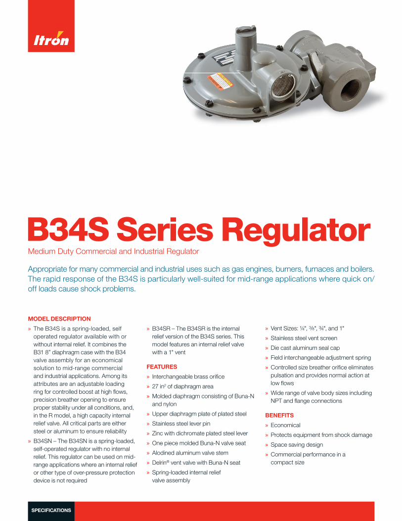
B34S Series RegulatorMedium Duty Commercial and Industrial Regulator
Appropriate for many commercial and industrial uses such as gas engines, burners, furnaces and boilers. The rapid response of the B34S is particularly well-suited for mid-range applications where quick on/off loads cause shock problems.
MODEL DESCRIPTION
» The B34S is a spring-loaded, self operated regulator available with or without internal relief. It combines the B31 8” diaphragm case with the B34 valve assembly for an economical solution to mid-range commercial and industrial applications. Among its attributes are an adjustable loading ring for controlled boost at high fl ows, precision breather opening to ensure proper stability under all conditions, and, in the R model, a high capacity internal relief valve. All critical parts are either steel or aluminum to ensure reliability
» B34SN – The B34SN is a spring-loaded, self-operated regulator with no internal relief. This regulator can be used on mid-range applications where an internal relief or other type of over-pressure protection device is not required
» B34SR – The B34SR is the internal relief version of the B34S series. This model features an internal relief valve with a 1" vent
FEATURES
» Interchangeable brass orifi ce
» 27 in2 of diaphragm area
» Molded diaphragm consisting of Buna-N and nylon
» Upper diaphragm plate of plated steel
» Stainless steel lever pin
» Zinc with dichromate plated steel lever
» One piece molded Buna-N valve seat
» Alodined aluminum valve stem
» Delrin® vent valve with Buna-N seat
» Spring-loaded internal relief valve assembly
» Vent Sizes: ¼ ", 3/8", ¾ ", and 1"
» Stainless steel vent screen
» Die cast aluminum seal cap
» Field interchangeable adjustment spring
» Controlled size breather orifi ce eliminates pulsation and provides normal action at low fl ows
» Wide range of valve body sizes including NPT and fl ange connections
BENEFITS
» Economical
» Protects equipment from shock damage
» Space saving design
» Commercial performance in a compact size
SPECIFICATIONS
B34S SERIES COMMERCIAL REGULATOR
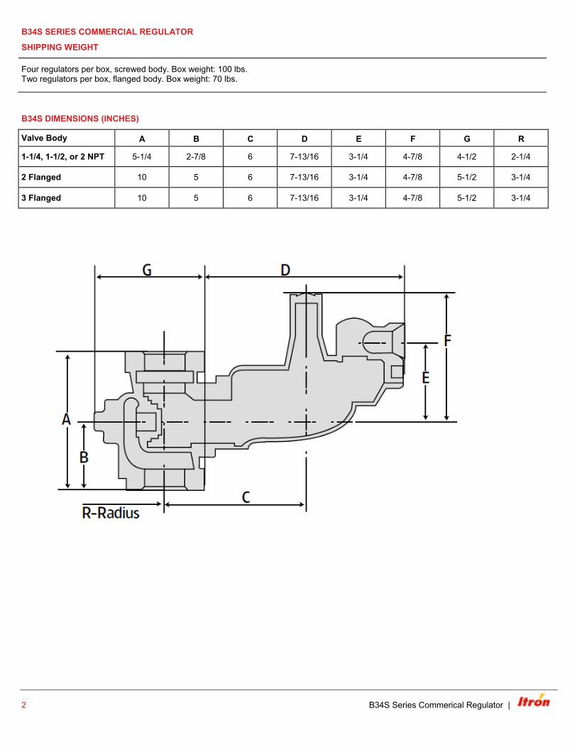
SHIPPING WEIGHT
Four regulators per box, screwed body. Box weight: 100 lbs. Two regulators per box, flanged body. Box weight: 70 lbs.
B34S DIMENSIONS (INCHES)
Valve Body A B C D E F G R
1-1/4, 1-1/2, or 2 NPT 5-1/4 2-7/8 6 7-13/16 3-1/4 4-7/8 4-1/2 2-1/4
2 Flanged 10 5 6 7-13/16 3-1/4 4-7/8 5-1/2 3-1/4
3 Flanged 10 5 6 7-13/16 3-1/4 4-7/8 5-1/2 3-1/4
2 B34S Series Commerical Regulator |
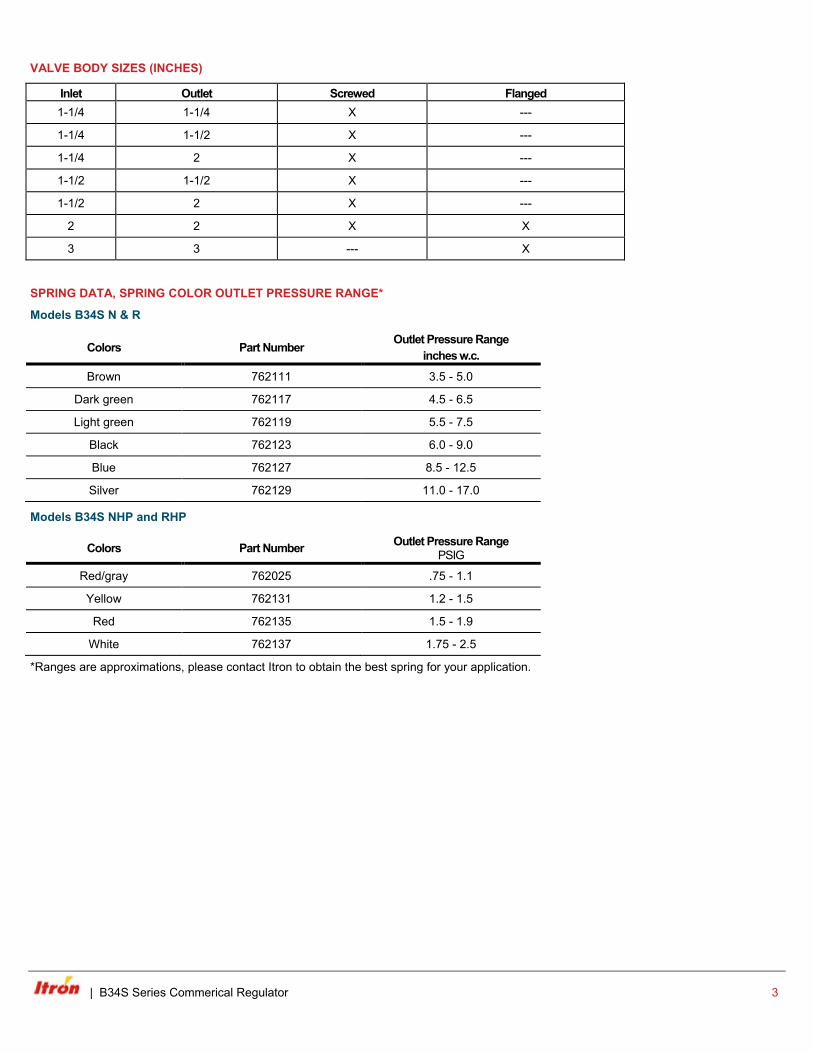
VALVE BODY SIZES (INCHES)
Inlet Outlet Screwed Flanged 1-1/4 1-1/4 X ---
1-1/4 1-1/2 X ---
1-1/4 2 X ---
1-1/2 1-1/2 X ---
1-1/2 2 X ---
2 2 X X
3 3 --- X
SPRING DATA, SPRING COLOR OUTLET PRESSURE RANGE*
Models B34S N & R
Colors Part Number Outlet Pressure Range inches w.c.
Brown 762111 3.5 - 5.0
Dark green 762117 4.5 - 6.5
Light green 762119 5.5 - 7.5
Black 762123 6.0 - 9.0
Blue 762127 8.5 - 12.5
Silver 762129 11.0 - 17.0
Models B34S NHP and RHP
Colors Part Number Outlet Pressure Range PSIG
Red/gray 762025 .75 - 1.1
Yellow 762131 1.2 - 1.5
Red 762135 1.5 - 1.9
White 762137 1.75 - 2.5
*Ranges are approximations, please contact Itron to obtain the best spring for your application.
| B34S Series Commerical Regulator 3
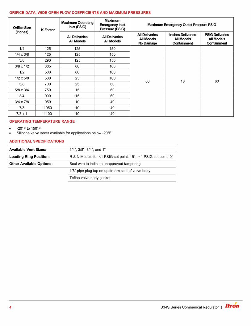
ORIFICE DATA, WIDE OPEN FLOW COEFFICIENTS AND MAXIMUM PRESSURES
Orifice Size (inches)
K-Factor
Maximum Operating Inlet (PSIG)
Maximum Emergency Inlet Pressure (PSIG)
Maximum Emergency Outlet Pressure PSIG
All Deliveries All Models
All Deliveries All Models
All Deliveries All Models No Damage
Inches Deliveries All Models
Containment
PSIG Deliveries All Models
Containment 1/4 125 125 150
60 18 60
1/4 x 3/8 125 125 150 3/8 290 125 150
3/8 x 1/2 305 60 100 1/2 500 60 100
1/2 x 5/8 530 25 100 5/8 700 25 60
5/8 x 3/4 750 15 60 3/4 900 15 60
3/4 x 7/8 950 10 40 7/8 1050 10 40
7/8 x 1 1100 10 40
OPERATING TEMPERATURE RANGE
• -20°F to 150°F • Silicone valve seats available for applications below -20°F
ADDITIONAL SPECIFICATIONS
Available Vent Sizes: 1/4", 3/8", 3/4", and 1"
Loading Ring Position: R & N Models for <1 PSIG set point: 15°, > 1 PSIG set point: 0°
Other Available Options: Seal wire to indicate unapproved tampering
1/8" pipe plug tap on upstream side of valve body
Teflon valve body gasket
4 B34S Series Commerical Regulator |
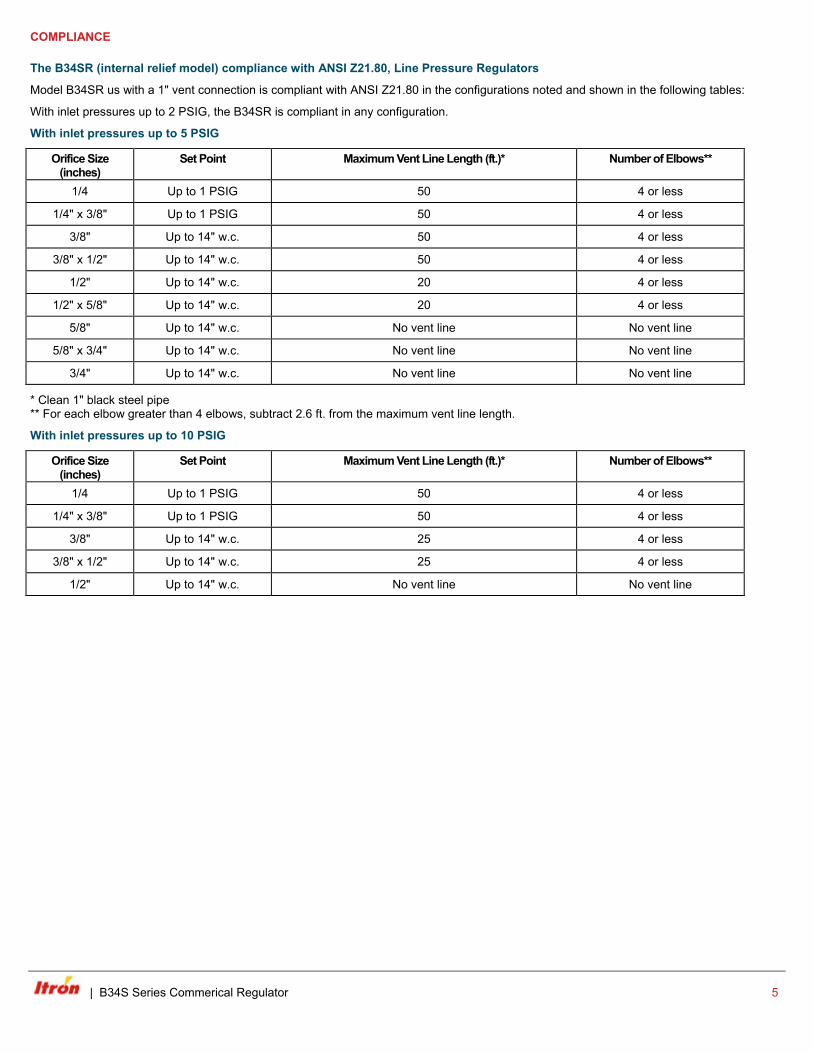
COMPLIANCE
The B34SR (internal relief model) compliance with ANSI Z21.80, Line Pressure Regulators
Model B34SR us with a 1" vent connection is compliant with ANSI Z21.80 in the configurations noted and shown in the following tables:
With inlet pressures up to 2 PSIG, the B34SR is compliant in any configuration.
With inlet pressures up to 5 PSIG
Orifice Size (inches)
Set Point Maximum Vent Line Length (ft.)* Number of Elbows**
1/4 Up to 1 PSIG 50 4 or less
1/4" x 3/8" Up to 1 PSIG 50 4 or less
3/8" Up to 14" w.c. 50 4 or less
3/8" x 1/2" Up to 14" w.c. 50 4 or less
1/2" Up to 14" w.c. 20 4 or less
1/2" x 5/8" Up to 14" w.c. 20 4 or less
5/8" Up to 14" w.c. No vent line No vent line
5/8" x 3/4" Up to 14" w.c. No vent line No vent line
3/4" Up to 14" w.c. No vent line No vent line
* Clean 1" black steel pipe ** For each elbow greater than 4 elbows, subtract 2.6 ft. from the maximum vent line length.
With inlet pressures up to 10 PSIG
Orifice Size (inches)
Set Point Maximum Vent Line Length (ft.)* Number of Elbows**
1/4 Up to 1 PSIG 50 4 or less
1/4" x 3/8" Up to 1 PSIG 50 4 or less
3/8" Up to 14" w.c. 25 4 or less
3/8" x 1/2" Up to 14" w.c. 25 4 or less
1/2" Up to 14" w.c. No vent line No vent line
| B34S Series Commerical Regulator 5
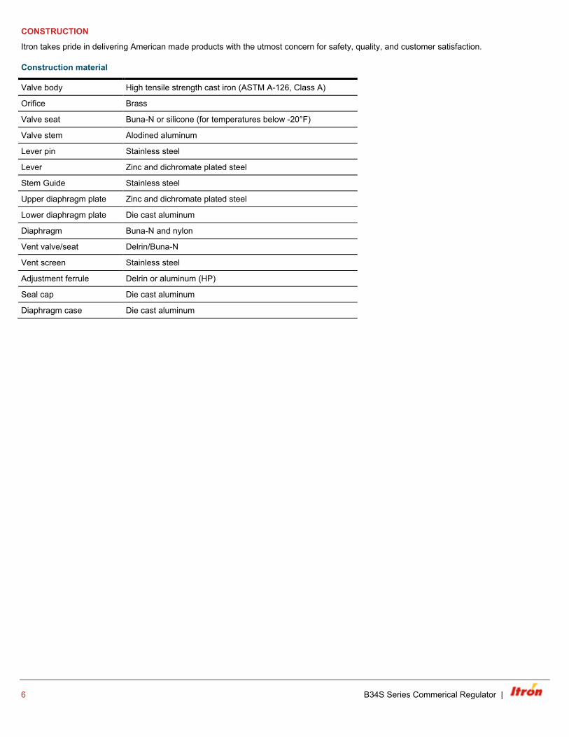
CONSTRUCTION
Itron takes pride in delivering American made products with the utmost concern for safety, quality, and customer satisfaction.
Construction material
Valve body High tensile strength cast iron (ASTM A-126, Class A)
Orifice Brass
Valve seat Buna-N or silicone (for temperatures below -20°F)
Valve stem Alodined aluminum
Lever pin Stainless steel
Lever Zinc and dichromate plated steel
Stem Guide Stainless steel
Upper diaphragm plate Zinc and dichromate plated steel
Lower diaphragm plate Die cast aluminum
Diaphragm Buna-N and nylon
Vent valve/seat Delrin/Buna-N
Vent screen Stainless steel
Adjustment ferrule Delrin or aluminum (HP)
Seal cap Die cast aluminum
Diaphragm case Die cast aluminum
6 B34S Series Commerical Regulator |
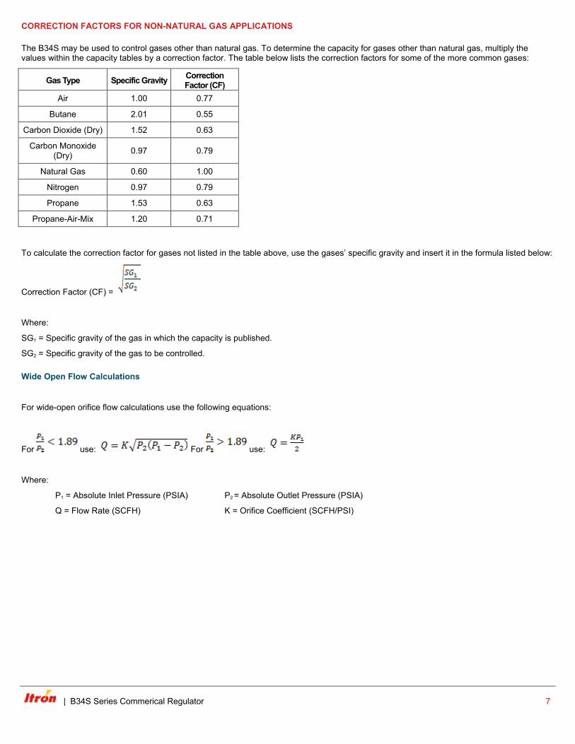
CORRECTION FACTORS FOR NON-NATURAL GAS APPLICATIONS
The B34S may be used to control gases other than natural gas. To determine the capacity for gases other than natural gas, multiply the values within the capacity tables by a correction factor. The table below lists the correction factors for some of the more common gases:
Gas Type Specific Gravity Correction Factor (CF)
Air 1.00 0.77
Butane 2.01 0.55
Carbon Dioxide (Dry) 1.52 0.63
Carbon Monoxide (Dry) 0.97 0.79
Natural Gas 0.60 1.00
Nitrogen 0.97 0.79
Propane 1.53 0.63
Propane-Air-Mix 1.20 0.71
To calculate the correction factor for gases not listed in the table above, use the gases’ specific gravity and insert it in the formula listed below:
Correction Factor (CF) =
Where:
SG1 = Specific gravity of the gas in which the capacity is published.
SG2 = Specific gravity of the gas to be controlled.
Wide Open Flow Calculations
For wide-open orifice flow calculations use the following equations:
For use: For use:
Where:
P1 = Absolute Inlet Pressure (PSIA) P2 = Absolute Outlet Pressure (PSIA)
Q = Flow Rate (SCFH) K = Orifice Coefficient (SCFH/PSI)
| B34S Series Commerical Regulator 7
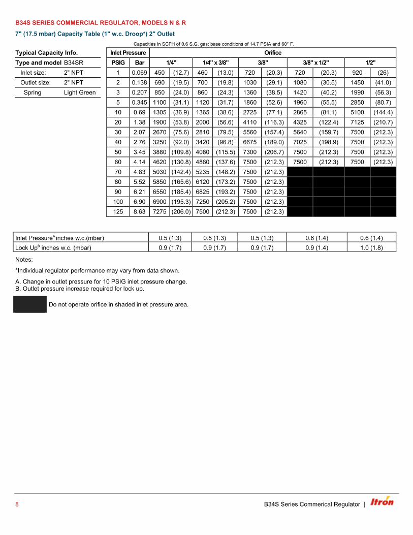
B34S SERIES COMMERCIAL REGULATOR, MODELS N & R
7" (17.5 mbar) Capacity Table (1" w.c. Droop*) 2" Outlet Capacities in SCFH of 0.6 S.G. gas; base conditions of 14.7 PSIA and 60° F.
Typical Capacity Info. Inlet Pressure Orifice Type and model B34SR PSIG Bar 1/4" 1/4" x 3/8" 3/8" 3/8" x 1/2" 1/2" Inlet size: 2" NPT 1 0.069 450 (12.7) 460 (13.0) 720 (20.3) 720 (20.3) 920 (26) Outlet size: 2" NPT 2 0.138 690 (19.5) 700 (19.8) 1030 (29.1) 1080 (30.5) 1450 (41.0) Spring Light Green 3 0.207 850 (24.0) 860 (24.3) 1360 (38.5) 1420 (40.2) 1990 (56.3) 5 0.345 1100 (31.1) 1120 (31.7) 1860 (52.6) 1960 (55.5) 2850 (80.7) 10 0.69 1305 (36.9) 1365 (38.6) 2725 (77.1) 2865 (81.1) 5100 (144.4)
20 1.38 1900 (53.8) 2000 (56.6) 4110 (116.3) 4325 (122.4) 7125 (210.7) 30 2.07 2670 (75.6) 2810 (79.5) 5560 (157.4) 5640 (159.7) 7500 (212.3) 40 2.76 3250 (92.0) 3420 (96.8) 6675 (189.0) 7025 (198.9) 7500 (212.3) 50 3.45 3880 (109.8) 4080 (115.5) 7300 (206.7) 7500 (212.3) 7500 (212.3) 60 4.14 4620 (130.8) 4860 (137.6) 7500 (212.3) 7500 (212.3) 7500 (212.3) 70 4.83 5030 (142.4) 5235 (148.2) 7500 (212.3) 80 5.52 5850 (165.6) 6120 (173.2) 7500 (212.3) 90 6.21 6550 (185.4) 6825 (193.2) 7500 (212.3) 100 6.90 6900 (195.3) 7250 (205.2) 7500 (212.3) 125 8.63 7275 (206.0) 7500 (212.3) 7500 (212.3)
Inlet PressureA inches w.c.(mbar) 0.5 (1.3) 0.5 (1.3) 0.5 (1.3) 0.6 (1.4) 0.6 (1.4) Lock UpB inches w.c. (mbar) 0.9 (1.7) 0.9 (1.7) 0.9 (1.7) 0.9 (1.4) 1.0 (1.8)
Notes:
*Individual regulator performance may vary from data shown.
A. Change in outlet pressure for 10 PSIG inlet pressure change. B. Outlet pressure increase required for lock up.
Do not operate orifice in shaded inlet pressure area.
8 B34S Series Commerical Regulator |
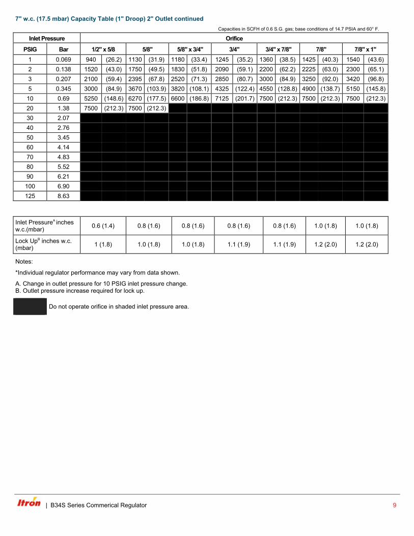
7" w.c. (17.5 mbar) Capacity Table (1" Droop) 2" Outlet continued Capacities in SCFH of 0.6 S.G. gas; base conditions of 14.7 PSIA and 60° F.
Inlet Pressure Orifice
PSIG Bar 1/2" x 5/8 5/8" 5/8" x 3/4" 3/4" 3/4" x 7/8" 7/8" 7/8" x 1" 1 0.069 940 (26.2) 1130 (31.9) 1180 (33.4) 1245 (35.2) 1360 (38.5) 1425 (40.3) 1540 (43.6) 2 0.138 1520 (43.0) 1750 (49.5) 1830 (51.8) 2090 (59.1) 2200 (62.2) 2225 (63.0) 2300 (65.1) 3 0.207 2100 (59.4) 2395 (67.8) 2520 (71.3) 2850 (80.7) 3000 (84.9) 3250 (92.0) 3420 (96.8) 5 0.345 3000 (84.9) 3670 (103.9) 3820 (108.1) 4325 (122.4) 4550 (128.8) 4900 (138.7) 5150 (145.8)
10 0.69 5250 (148.6) 6270 (177.5) 6600 (186.8) 7125 (201.7) 7500 (212.3) 7500 (212.3) 7500 (212.3) 20 1.38 7500 (212.3) 7500 (212.3) 4110 (116.3) 4325 (122.4) 7125 (210.7) 30 2.07 2670 (75.6) 2810 (79.5) 5560 (157.4) 5640 (159.7) 7500 (212.3) 40 2.76 50 3.45 60 4.14 70 4.83 80 5.52 90 6.21 100 6.90 125 8.63
Inlet PressureA inches w.c.(mbar) 0.6 (1.4) 0.8 (1.6) 0.8 (1.6) 0.8 (1.6) 0.8 (1.6) 1.0 (1.8) 1.0 (1.8)
Lock UpB inches w.c. (mbar) 1 (1.8) 1.0 (1.8) 1.0 (1.8) 1.1 (1.9) 1.1 (1.9) 1.2 (2.0) 1.2 (2.0)
Notes:
*Individual regulator performance may vary from data shown.
A. Change in outlet pressure for 10 PSIG inlet pressure change. B. Outlet pressure increase required for lock up.
Do not operate orifice in shaded inlet pressure area.
| B34S Series Commerical Regulator 9
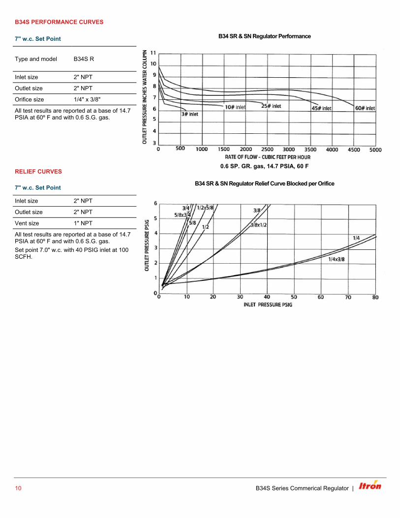
B34S PERFORMANCE CURVES
7" w.c. Set Point B34 SR & SN Regulator Performance
Type and model B34S R
0.6 SP. GR. gas, 14.7 PSIA, 60 F
Inlet size 2" NPT
Outlet size 2" NPT
Orifice size 1/4" x 3/8"
All test results are reported at a base of 14.7 PSIA at 60º F and with 0.6 S.G. gas.
RELIEF CURVES
7" w.c. Set Point B34 SR & SN Regulator Relief Curve Blocked per Orifice
Inlet size 2" NPT
Outlet size 2" NPT
Vent size 1" NPT
All test results are reported at a base of 14.7 PSIA at 60º F and with 0.6 S.G. gas. Set point 7.0" w.c. with 40 PSIG inlet at 100 SCFH.
10 B34S Series Commerical Regulator |
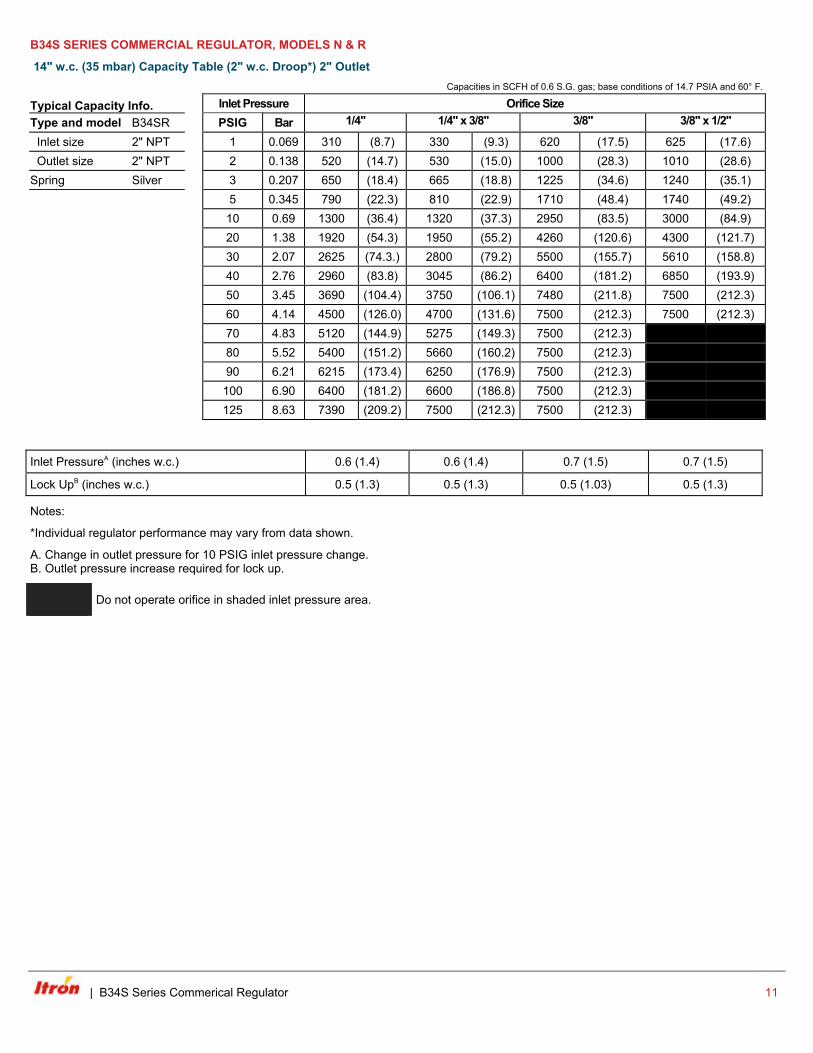
B34S SERIES COMMERCIAL REGULATOR, MODELS N & R
14" w.c. (35 mbar) Capacity Table (2" w.c. Droop*) 2" Outlet Capacities in SCFH of 0.6 S.G. gas; base conditions of 14.7 PSIA and 60° F.
Typical Capacity Info. Inlet Pressure Orifice Size Type and model B34SR PSIG Bar 1/4"
1/4" x 3/8"
3/8"
3/8" x 1/2"
Inlet size 2" NPT 1 0.069 310 (8.7) 330 (9.3) 620 (17.5) 625 (17.6) Outlet size 2" NPT 2 0.138 520 (14.7) 530 (15.0) 1000 (28.3) 1010 (28.6) Spring Silver 3 0.207 650 (18.4) 665 (18.8) 1225 (34.6) 1240 (35.1) 5 0.345 790 (22.3) 810 (22.9) 1710 (48.4) 1740 (49.2) 10 0.69 1300 (36.4) 1320 (37.3) 2950 (83.5) 3000 (84.9)
20 1.38 1920 (54.3) 1950 (55.2) 4260 (120.6) 4300 (121.7) 30 2.07 2625 (74.3.) 2800 (79.2) 5500 (155.7) 5610 (158.8) 40 2.76 2960 (83.8) 3045 (86.2) 6400 (181.2) 6850 (193.9) 50 3.45 3690 (104.4) 3750 (106.1) 7480 (211.8) 7500 (212.3) 60 4.14 4500 (126.0) 4700 (131.6) 7500 (212.3) 7500 (212.3) 70 4.83 5120 (144.9) 5275 (149.3) 7500 (212.3) 80 5.52 5400 (151.2) 5660 (160.2) 7500 (212.3) 90 6.21 6215 (173.4) 6250 (176.9) 7500 (212.3) 100 6.90 6400 (181.2) 6600 (186.8) 7500 (212.3) 125 8.63 7390 (209.2) 7500 (212.3) 7500 (212.3)
Inlet PressureA (inches w.c.) 0.6 (1.4) 0.6 (1.4) 0.7 (1.5) 0.7 (1.5)
Lock UpB (inches w.c.) 0.5 (1.3) 0.5 (1.3) 0.5 (1.03) 0.5 (1.3)
Notes:
*Individual regulator performance may vary from data shown.
A. Change in outlet pressure for 10 PSIG inlet pressure change. B. Outlet pressure increase required for lock up.
Do not operate orifice in shaded inlet pressure area.
| B34S Series Commerical Regulator 11
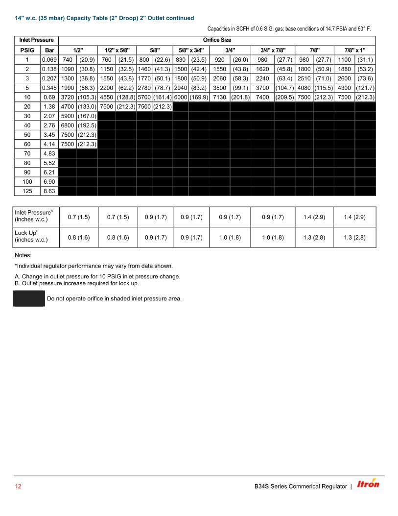
14" w.c. (35 mbar) Capacity Table (2" Droop) 2" Outlet continued
Capacities in SCFH of 0.6 S.G. gas; base conditions of 14.7 PSIA and 60° F.
Inlet Pressure
Orifice Size PSIG Bar 1/2" 1/2" x 5/8" 5/8" 5/8" x 3/4" 3/4" 3/4" x 7/8" 7/8" 7/8" x 1"
1 0.069 740 (20.9) 760 (21.5) 800 (22.6) 830 (23.5) 920 (26.0) 980 (27.7) 980 (27.7) 1100 (31.1) 2 0.138 1090 (30.8) 1150 (32.5) 1460 (41.3) 1500 (42.4) 1550 (43.8) 1620 (45.8) 1800 (50.9) 1880 (53.2) 3 0.207 1300 (36.8) 1550 (43.8) 1770 (50.1) 1800 (50.9) 2060 (58.3) 2240 (63.4) 2510 (71.0) 2600 (73.6) 5 0.345 1990 (56.3) 2200 (62.2) 2780 (78.7) 2940 (83.2) 3500 (99.1) 3700 (104.7) 4080 (115.5) 4300 (121.7)
10 0.69 3720 (105.3) 4550 (128.8) 5700 (161.4) 6000 (169.9) 7130 (201.8) 7400 (209.5) 7500 (212.3) 7500 (212.3) 20 1.38 4700 (133.0) 7500 (212.3) 7500 (212.3) 30 2.07 5900 (167.0) 40 2.76 6800 (192.5) 50 3.45 7500 (212.3) 60 4.14 7500 (212.3) 70 4.83 80 5.52 90 6.21 100 6.90 125 8.63
Inlet PressureA (inches w.c.) 0.7 (1.5) 0.7 (1.5) 0.9 (1.7) 0.9 (1.7) 0.9 (1.7) 0.9 (1.7) 1.4 (2.9) 1.4 (2.9)
Lock UpB (inches w.c.) 0.8 (1.6) 0.8 (1.6) 0.9 (1.7) 0.9 (1.7) 1.0 (1.8) 1.0 (1.8) 1.3 (2.8) 1.3 (2.8)
Notes:
*Individual regulator performance may vary from data shown.
A. Change in outlet pressure for 10 PSIG inlet pressure change. B. Outlet pressure increase required for lock up.
Do not operate orifice in shaded inlet pressure area.
12 B34S Series Commerical Regulator |
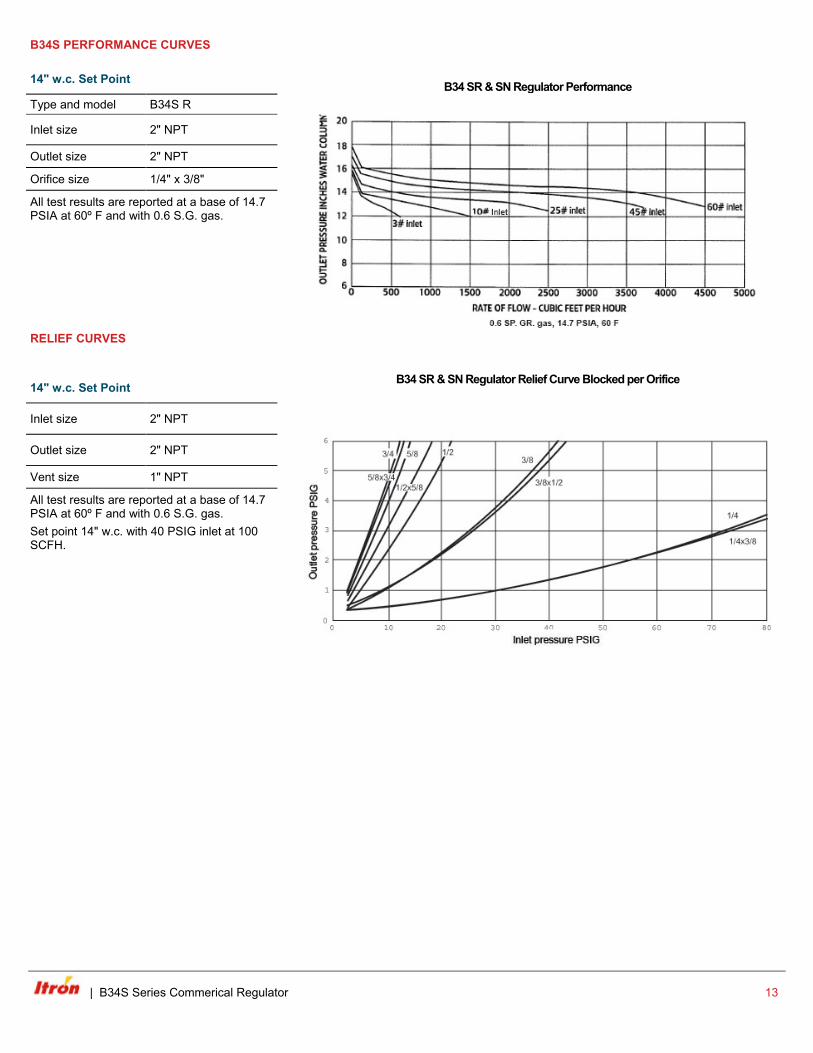
B34S PERFORMANCE CURVES
14" w.c. Set Point B34 SR & SN Regulator Performance Type and model B34S R
Inlet size 2" NPT
Outlet size 2" NPT
Orifice size 1/4" x 3/8"
All test results are reported at a base of 14.7 PSIA at 60º F and with 0.6 S.G. gas.
RELIEF CURVES
14" w.c. Set Point
B34 SR & SN Regulator Relief Curve Blocked per Orifice
Inlet size 2" NPT
Outlet size 2" NPT
Vent size 1" NPT
All test results are reported at a base of 14.7 PSIA at 60º F and with 0.6 S.G. gas. Set point 14" w.c. with 40 PSIG inlet at 100 SCFH.
| B34S Series Commerical Regulator 13
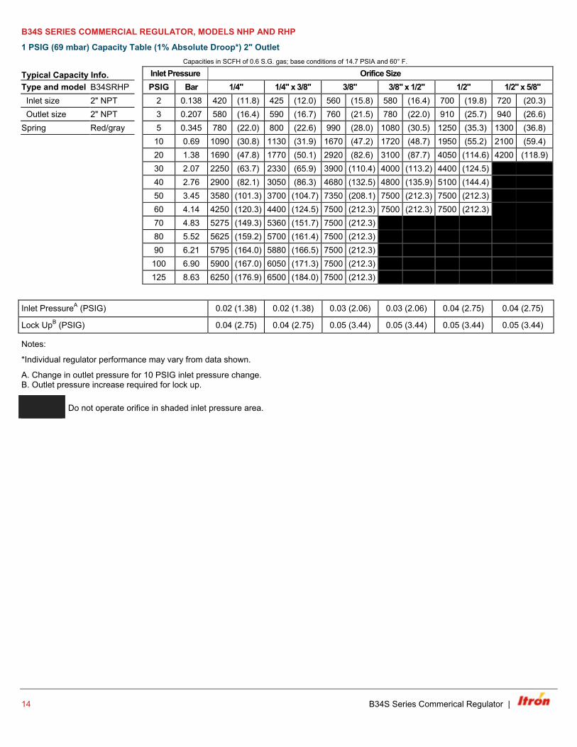
B34S SERIES COMMERCIAL REGULATOR, MODELS NHP AND RHP
1 PSIG (69 mbar) Capacity Table (1% Absolute Droop*) 2" Outlet Capacities in SCFH of 0.6 S.G. gas; base conditions of 14.7 PSIA and 60° F.
Typical Capacity Info. Inlet Pressure Orifice Size Type and model B34SRHP PSIG Bar 1/4" 1/4" x 3/8" 3/8" 3/8" x 1/2" 1/2" 1/2" x 5/8" Inlet size 2" NPT 2 0.138 420 (11.8) 425 (12.0) 560 (15.8) 580 (16.4) 700 (19.8) 720 (20.3) Outlet size 2" NPT 3 0.207 580 (16.4) 590 (16.7) 760 (21.5) 780 (22.0) 910 (25.7) 940 (26.6) Spring Red/gray 5 0.345 780 (22.0) 800 (22.6) 990 (28.0) 1080 (30.5) 1250 (35.3) 1300 (36.8) 10 0.69 1090 (30.8) 1130 (31.9) 1670 (47.2) 1720 (48.7) 1950 (55.2) 2100 (59.4) 20 1.38 1690 (47.8) 1770 (50.1) 2920 (82.6) 3100 (87.7) 4050 (114.6) 4200 (118.9) 30 2.07 2250 (63.7) 2330 (65.9) 3900 (110.4) 4000 (113.2) 4400 (124.5)
40 2.76 2900 (82.1) 3050 (86.3) 4680 (132.5) 4800 (135.9) 5100 (144.4) 50 3.45 3580 (101.3) 3700 (104.7) 7350 (208.1) 7500 (212.3) 7500 (212.3) 60 4.14 4250 (120.3) 4400 (124.5) 7500 (212.3) 7500 (212.3) 7500 (212.3) 70 4.83 5275 (149.3) 5360 (151.7) 7500 (212.3) 80 5.52 5625 (159.2) 5700 (161.4) 7500 (212.3) 90 6.21 5795 (164.0) 5880 (166.5) 7500 (212.3) 100 6.90 5900 (167.0) 6050 (171.3) 7500 (212.3) 125 8.63 6250 (176.9) 6500 (184.0) 7500 (212.3)
Inlet PressureA (PSIG) 0.02 (1.38) 0.02 (1.38) 0.03 (2.06) 0.03 (2.06) 0.04 (2.75) 0.04 (2.75)
Lock UpB (PSIG) 0.04 (2.75) 0.04 (2.75) 0.05 (3.44) 0.05 (3.44) 0.05 (3.44) 0.05 (3.44)
Notes:
*Individual regulator performance may vary from data shown.
A. Change in outlet pressure for 10 PSIG inlet pressure change. B. Outlet pressure increase required for lock up.
Do not operate orifice in shaded inlet pressure area.
14 B34S Series Commerical Regulator |
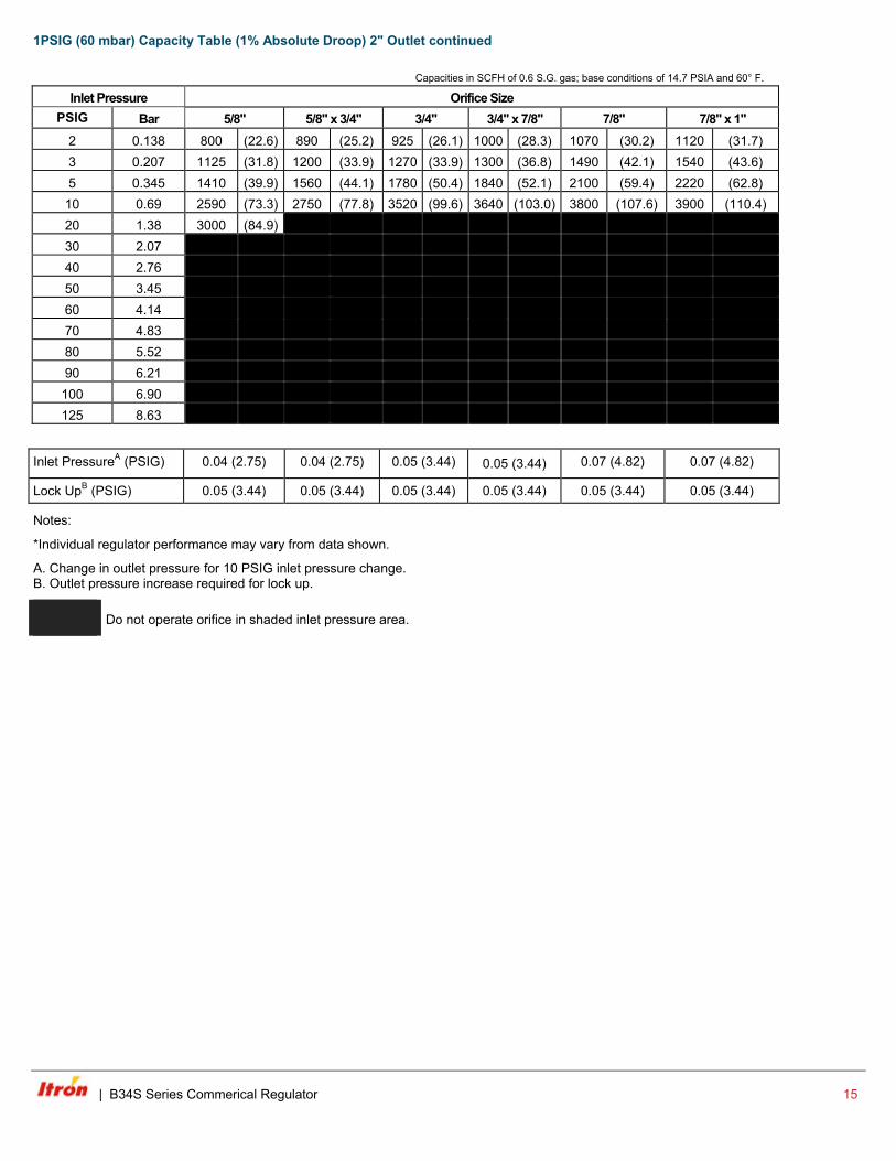
1PSIG (60 mbar) Capacity Table (1% Absolute Droop) 2" Outlet continued Capacities in SCFH of 0.6 S.G. gas; base conditions of 14.7 PSIA and 60° F.
Inlet Pressure Orifice Size PSIG Bar 5/8" 5/8" x 3/4" 3/4" 3/4" x 7/8" 7/8" 7/8" x 1"
2 0.138 800 (22.6) 890 (25.2) 925 (26.1) 1000 (28.3) 1070 (30.2) 1120 (31.7) 3 0.207 1125 (31.8) 1200 (33.9) 1270 (33.9) 1300 (36.8) 1490 (42.1) 1540 (43.6) 5 0.345 1410 (39.9) 1560 (44.1) 1780 (50.4) 1840 (52.1) 2100 (59.4) 2220 (62.8)
10 0.69 2590 (73.3) 2750 (77.8) 3520 (99.6) 3640 (103.0) 3800 (107.6) 3900 (110.4) 20 1.38 3000 (84.9) 30 2.07 40 2.76 50 3.45 60 4.14 70 4.83 80 5.52 90 6.21 100 6.90 125 8.63
Inlet PressureA (PSIG) 0.04 (2.75) 0.04 (2.75) 0.05 (3.44) 0.05 (3.44) 0.07 (4.82) 0.07 (4.82)
Lock UpB (PSIG) 0.05 (3.44) 0.05 (3.44) 0.05 (3.44) 0.05 (3.44) 0.05 (3.44) 0.05 (3.44)
Notes:
*Individual regulator performance may vary from data shown.
A. Change in outlet pressure for 10 PSIG inlet pressure change. B. Outlet pressure increase required for lock up.
Do not operate orifice in shaded inlet pressure area.
| B34S Series Commerical Regulator 15
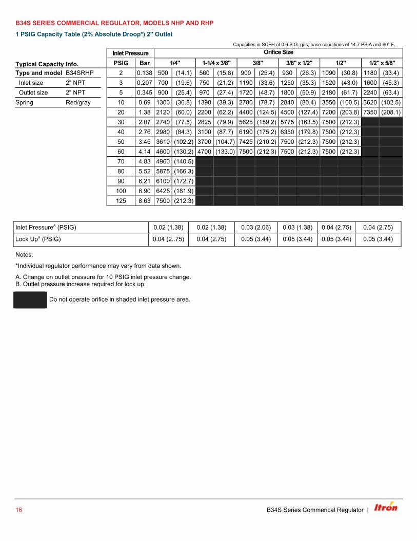
B34S SERIES COMMERCIAL REGULATOR, MODELS NHP AND RHP
1 PSIG Capacity Table (2% Absolute Droop*) 2" Outlet Capacities in SCFH of 0.6 S.G. gas; base conditions of 14.7 PSIA and 60° F.
Typical Capacity Info.
Inlet Pressure Orifice Size PSIG Bar 1/4" 1-1/4 x 3/8" 3/8" 3/8" x 1/2" 1/2" 1/2" x 5/8"
Type and model B34SRHP 2 0.138 500 (14.1) 560 (15.8) 900 (25.4) 930 (26.3) 1090 (30.8) 1180 (33.4) Inlet size 2" NPT 3 0.207 700 (19.6) 750 (21.2) 1190 (33.6) 1250 (35.3) 1520 (43.0) 1600 (45.3) Outlet size 2" NPT 5 0.345 900 (25.4) 970 (27.4) 1720 (48.7) 1800 (50.9) 2180 (61.7) 2240 (63.4) Spring Red/gray 10 0.69 1300 (36.8) 1390 (39.3) 2780 (78.7) 2840 (80.4) 3550 (100.5) 3620 (102.5) 20 1.38 2120 (60.0) 2200 (62.2) 4400 (124.5) 4500 (127.4) 7200 (203.8) 7350 (208.1)
30 2.07 2740 (77.5) 2825 (79.9) 5625 (159.2) 5775 (163.5) 7500 (212.3) 40 2.76 2980 (84.3) 3100 (87.7) 6190 (175.2) 6350 (179.8) 7500 (212.3) 50 3.45 3610 (102.2) 3700 (104.7) 7425 (210.2) 7500 (212.3) 7500 (212.3) 60 4.14 4600 (130.2) 4700 (133.0) 7500 (212.3) 7500 (212.3) 7500 (212.3) 70 4.83 4960 (140.5) 80 5.52 5875 (166.3) 90 6.21 6100 (172.7) 100 6.90 6425 (181.9) 125 8.63 7500 (212.3)
Inlet PressureA (PSIG) 0.02 (1.38) 0.02 (1.38) 0.03 (2.06) 0.03 (1.38) 0.04 (2.75) 0.04 (2.75)
Lock UpB (PSIG) 0.04 (2..75) 0.04 (2.75) 0.05 (3.44) 0.05 (3.44) 0.05 (3.44) 0.05 (3.44)
Notes:
*Individual regulator performance may vary from data shown.
A. Change on outlet pressure for 10 PSIG inlet pressure change. B. Outlet pressure increase required for lock up.
Do not operate orifice in shaded inlet pressure area.
16 B34S Series Commerical Regulator |
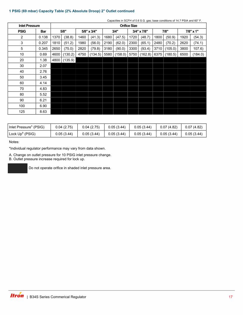
1 PSIG (69 mbar) Capacity Table (2% Absolute Droop) 2" Outlet continued Capacities in SCFH of 0.6 S.G. gas; base conditions of 14.7 PSIA and 60° F.
Inlet Pressure Orifice Size PSIG Bar 5/8" 5/8" x 3/4" 3/4" 3/4" x 7/8" 7/8" 7/8" x 1"
2 0.138 1370 (38.8) 1460 (41.3) 1680 (47.5) 1720 (48.7) 1800 (50.9) 1920 (54.3) 3 0.207 1810 (51.2) 1980 (56.0) 2190 (62.0) 2300 (65.1) 2480 (70.2) 2620 (74.1) 5 0.345 2650 (75.0) 2820 (79.8) 3180 (90.0) 3300 (93.4) 3710 (105.0) 3800 107.6)
10 0.69 4600 (130.2) 4750 (134.5) 5580 (158.0) 5750 (162.8) 6375 (180.5) 6500 (184.0) 20 1.38 4800 (135.9) 2200 (62.2) 4400 (124.5) 4500 (127.4) 7200 (203.8) 7350 (208.1) 30 2.07 2825 (79.9) 5625 (159.2) 5775 (163.5) 7500 (212.3) 40 2.76 3100 (87.7) 6190 (175.2) 6350 (179.8) 7500 (212.3) 50 3.45 3700 (104.7) 7425 (210.2) 7500 (212.3) 7500 (212.3) 60 4.14 4700 (133.0) 7500 (212.3) 7500 (212.3) 7500 (212.3) 70 4.83 80 5.52 90 6.21
100 6.90 125 8.63
Inlet PressureA (PSIG) 0.04 (2.75) 0.04 (2.75) 0.05 (3.44) 0.05 (3.44) 0.07 (4.82) 0.07 (4.82)
Lock UpB (PSIG) 0.05 (3.44) 0.05 (3.44) 0.05 (3.44) 0.05 (3.44) 0.05 (3.44) 0.05 (3.44)
Notes:
*Individual regulator performance may vary from data shown.
A. Change on outlet pressure for 10 PSIG inlet pressure change. B. Outlet pressure increase required for lock up.
Do not operate orifice in shaded inlet pressure area.
| B34S Series Commerical Regulator 17
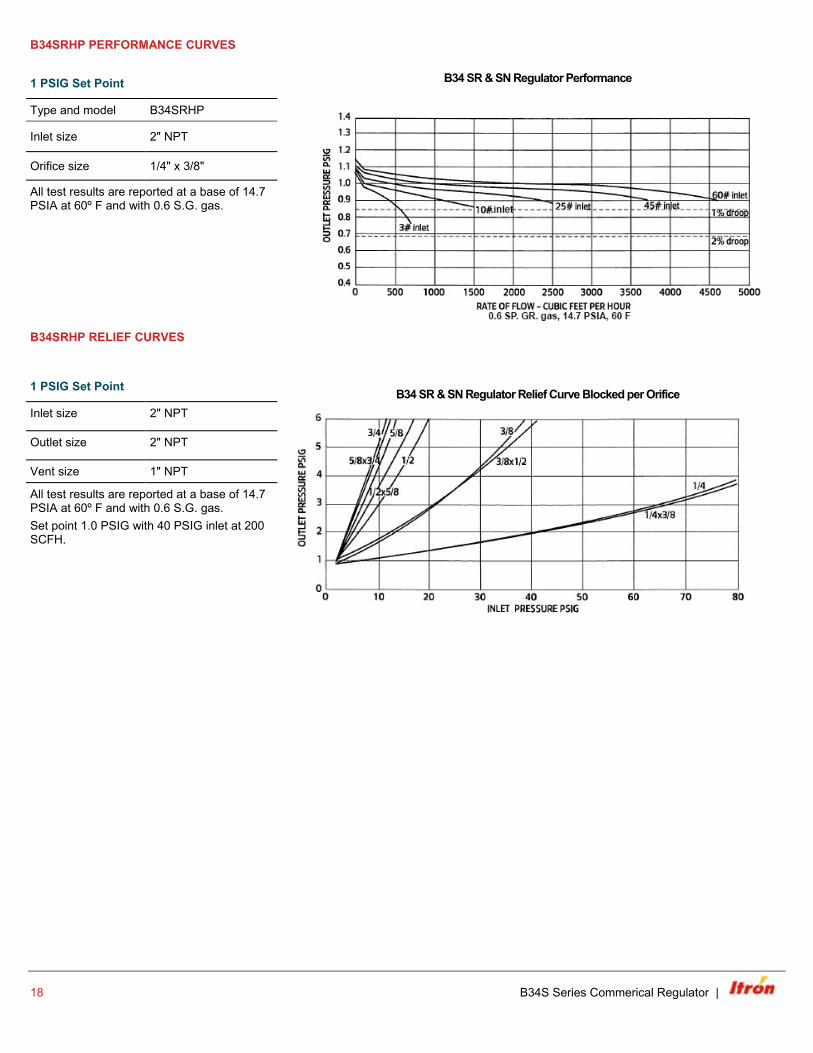
B34SRHP PERFORMANCE CURVES
1 PSIG Set Point B34 SR & SN Regulator Performance
Type and model B34SRHP
Inlet size 2" NPT
Orifice size 1/4" x 3/8"
All test results are reported at a base of 14.7 PSIA at 60º F and with 0.6 S.G. gas.
B34SRHP RELIEF CURVES
1 PSIG Set Point
B34 SR & SN Regulator Relief Curve Blocked per Orifice Inlet size 2" NPT
Outlet size 2" NPT
Vent size 1" NPT
All test results are reported at a base of 14.7 PSIA at 60º F and with 0.6 S.G. gas. Set point 1.0 PSIG with 40 PSIG inlet at 200 SCFH.
18 B34S Series Commerical Regulator |
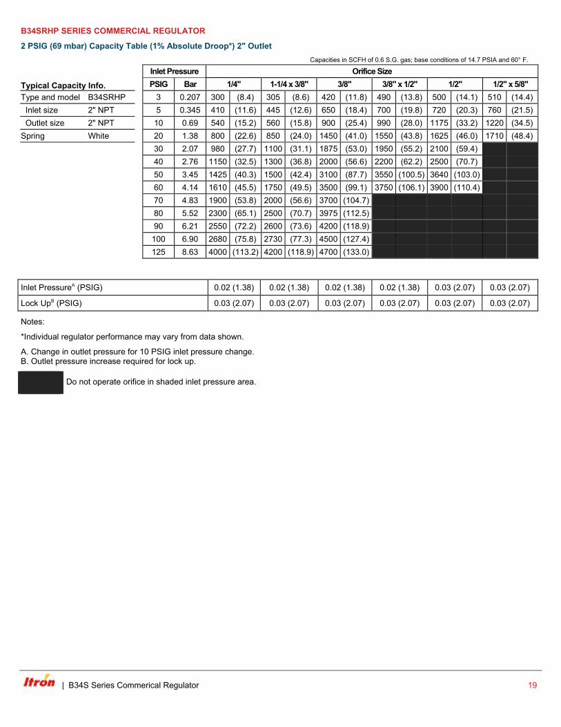
B34SRHP SERIES COMMERCIAL REGULATOR
2 PSIG (69 mbar) Capacity Table (1% Absolute Droop*) 2" Outlet Capacities in SCFH of 0.6 S.G. gas; base conditions of 14.7 PSIA and 60° F.
Typical Capacity Info.
Inlet Pressure Orifice Size PSIG Bar 1/4" 1-1/4 x 3/8" 3/8" 3/8" x 1/2" 1/2" 1/2" x 5/8"
Type and model B34SRHP 3 0.207 300 (8.4) 305 (8.6) 420 (11.8) 490 (13.8) 500 (14.1) 510 (14.4) Inlet size 2" NPT 5 0.345 410 (11.6) 445 (12.6) 650 (18.4) 700 (19.8) 720 (20.3) 760 (21.5) Outlet size 2" NPT 10 0.69 540 (15.2) 560 (15.8) 900 (25.4) 990 (28.0) 1175 (33.2) 1220 (34.5) Spring White 20 1.38 800 (22.6) 850 (24.0) 1450 (41.0) 1550 (43.8) 1625 (46.0) 1710 (48.4)
30 2.07 980 (27.7) 1100 (31.1) 1875 (53.0) 1950 (55.2) 2100 (59.4) 40 2.76 1150 (32.5) 1300 (36.8) 2000 (56.6) 2200 (62.2) 2500 (70.7) 50 3.45 1425 (40.3) 1500 (42.4) 3100 (87.7) 3550 (100.5) 3640 (103.0) 60 4.14 1610 (45.5) 1750 (49.5) 3500 (99.1) 3750 (106.1) 3900 (110.4) 70 4.83 1900 (53.8) 2000 (56.6) 3700 (104.7) 80 5.52 2300 (65.1) 2500 (70.7) 3975 (112.5) 90 6.21 2550 (72.2) 2600 (73.6) 4200 (118.9) 100 6.90 2680 (75.8) 2730 (77.3) 4500 (127.4) 125 8.63 4000 (113.2) 4200 (118.9) 4700 (133.0)
Inlet PressureA (PSIG) 0.02 (1.38) 0.02 (1.38) 0.02 (1.38) 0.02 (1.38) 0.03 (2.07) 0.03 (2.07)
Lock UpB (PSIG) 0.03 (2.07) 0.03 (2.07) 0.03 (2.07) 0.03 (2.07) 0.03 (2.07) 0.03 (2.07)
Notes:
*Individual regulator performance may vary from data shown.
A. Change in outlet pressure for 10 PSIG inlet pressure change. B. Outlet pressure increase required for lock up.
Do not operate orifice in shaded inlet pressure area.
| B34S Series Commerical Regulator 19

2 PSIG (69 mbar) Capacity Table (1% Absolute Droop*) 2" Outlet continued Capacities in SCFH of 0.6 S.G. gas; base conditions of 14.7 PSIA and 60° F.
Inlet Pressure Orifice Size PSIG Bar 5/8" 5/8 x 3/4" 3/4" 3/4" x 7/8" 7/8" 7/8" x 1"
3 0.207 550 (15.1) 600 (16.9) 625 (17.6) 650 (18.4) 750 (21.2) 770 (21.8) 5 0.345 800 (22.6) 860 (24.3) 925 (26.1) 1030 (29.1) 1100 (31.1) 1170 (33.1)
10 0.69 1300 (36.8) 1420 (40.2) 1650 (46.7) 1740 (49.2) 1900 (53.8) 2040 (57.7) 20 1.38 1500 (42.4) 30 2.07 40 2.76 50 3.45 60 4.14 70 4.83 80 5.52 90 6.21
100 6.90 125 8.63
Inlet PressureA (PSIG) 0.03 (2.07) 0.03 (2.07) 0.03 (2.07) 0.03 (2.07) 0.03 (2.07) 0.03 (2.07)
Lock UpB (PSIG) 0.04 (2.76) 0.04 (2.76) 0.04 (2.76) 0.06 (4.14) 0.07 (4.83) 0.07 (4.83)
Notes:
*Individual regulator performance may vary from data shown.
A. Change in outlet pressure for 10 PSIG inlet pressure change. B. Outlet pressure increase required for lock up.
Do not operate orifice in shaded inlet pressure area.
20 B34S Series Commerical Regulator |
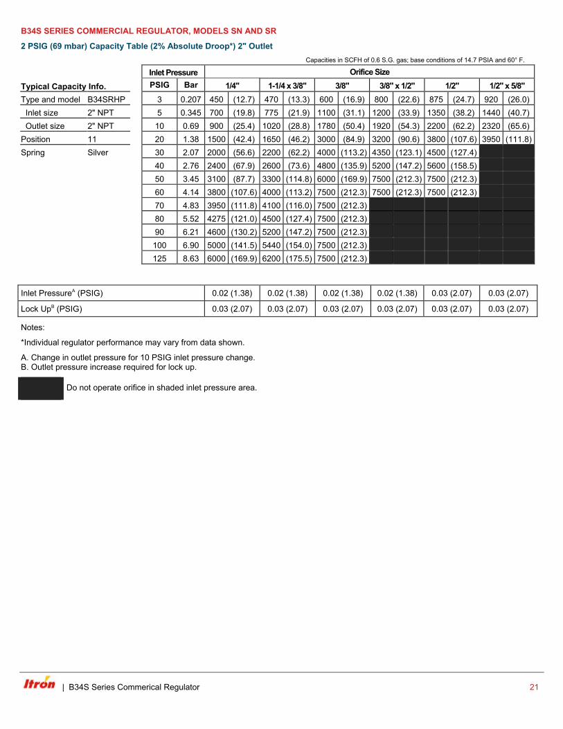
B34S SERIES COMMERCIAL REGULATOR, MODELS SN AND SR
2 PSIG (69 mbar) Capacity Table (2% Absolute Droop*) 2" Outlet Capacities in SCFH of 0.6 S.G. gas; base conditions of 14.7 PSIA and 60° F.
Typical Capacity Info.
Inlet Pressure Orifice Size PSIG Bar 1/4" 1-1/4 x 3/8" 3/8" 3/8" x 1/2" 1/2" 1/2" x 5/8"
Type and model B34SRHP 3 0.207 450 (12.7) 470 (13.3) 600 (16.9) 800 (22.6) 875 (24.7) 920 (26.0) Inlet size 2" NPT 5 0.345 700 (19.8) 775 (21.9) 1100 (31.1) 1200 (33.9) 1350 (38.2) 1440 (40.7) Outlet size 2" NPT 10 0.69 900 (25.4) 1020 (28.8) 1780 (50.4) 1920 (54.3) 2200 (62.2) 2320 (65.6) Position 11 20 1.38 1500 (42.4) 1650 (46.2) 3000 (84.9) 3200 (90.6) 3800 (107.6) 3950 (111.8) Spring Silver 30 2.07 2000 (56.6) 2200 (62.2) 4000 (113.2) 4350 (123.1) 4500 (127.4)
40 2.76 2400 (67.9) 2600 (73.6) 4800 (135.9) 5200 (147.2) 5600 (158.5)
50 3.45 3100 (87.7) 3300 (114.8) 6000 (169.9) 7500 (212.3) 7500 (212.3)
60 4.14 3800 (107.6) 4000 (113.2) 7500 (212.3) 7500 (212.3) 7500 (212.3)
70 4.83 3950 (111.8) 4100 (116.0) 7500 (212.3)
80 5.52 4275 (121.0) 4500 (127.4) 7500 (212.3)
90 6.21 4600 (130.2) 5200 (147.2) 7500 (212.3)
100 6.90 5000 (141.5) 5440 (154.0) 7500 (212.3)
125 8.63 6000 (169.9) 6200 (175.5) 7500 (212.3)
Inlet PressureA (PSIG) 0.02 (1.38) 0.02 (1.38) 0.02 (1.38) 0.02 (1.38) 0.03 (2.07) 0.03 (2.07)
Lock UpB (PSIG) 0.03 (2.07) 0.03 (2.07) 0.03 (2.07) 0.03 (2.07) 0.03 (2.07) 0.03 (2.07)
Notes:
*Individual regulator performance may vary from data shown.
A. Change in outlet pressure for 10 PSIG inlet pressure change. B. Outlet pressure increase required for lock up.
Do not operate orifice in shaded inlet pressure area.
| B34S Series Commerical Regulator 21
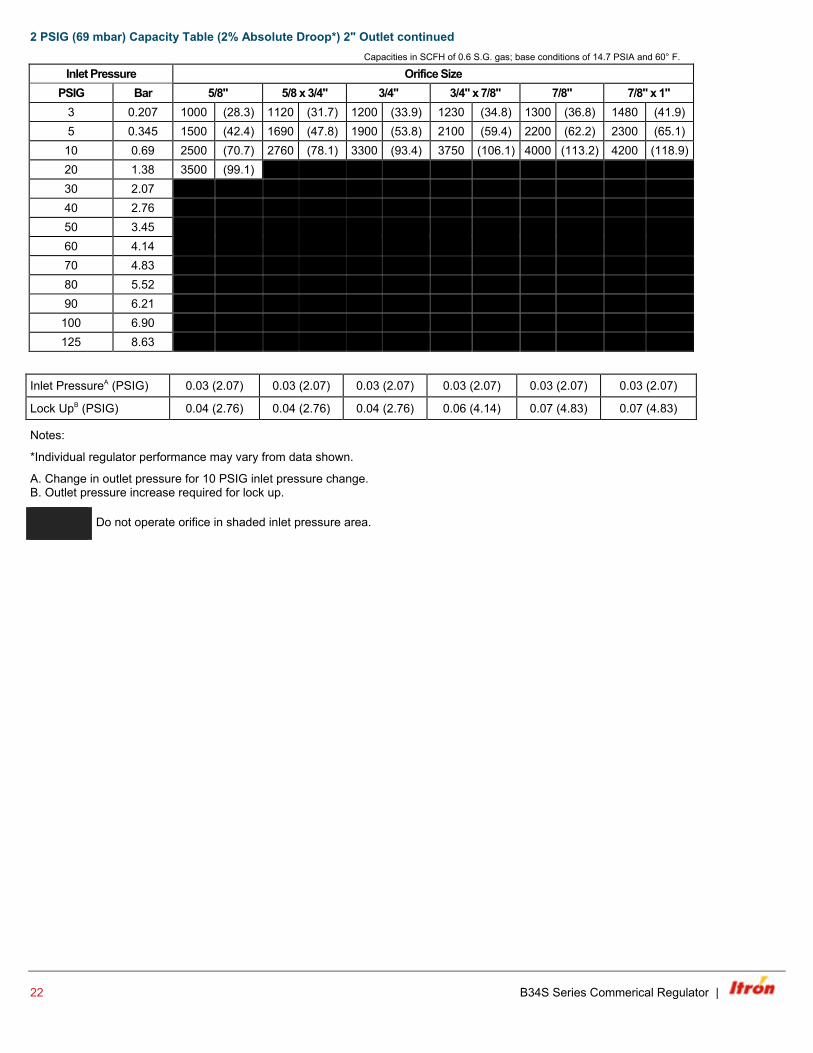
2 PSIG (69 mbar) Capacity Table (2% Absolute Droop*) 2" Outlet continued Capacities in SCFH of 0.6 S.G. gas; base conditions of 14.7 PSIA and 60° F.
Inlet Pressure Orifice Size PSIG Bar 5/8" 5/8 x 3/4" 3/4" 3/4" x 7/8" 7/8" 7/8" x 1"
3 0.207 1000 (28.3) 1120 (31.7) 1200 (33.9) 1230 (34.8) 1300 (36.8) 1480 (41.9) 5 0.345 1500 (42.4) 1690 (47.8) 1900 (53.8) 2100 (59.4) 2200 (62.2) 2300 (65.1)
10 0.69 2500 (70.7) 2760 (78.1) 3300 (93.4) 3750 (106.1) 4000 (113.2) 4200 (118.9) 20 1.38 3500 (99.1) 30 2.07 40 2.76 50 3.45 60 4.14 70 4.83 80 5.52 90 6.21
100 6.90 125 8.63
Inlet PressureA (PSIG) 0.03 (2.07) 0.03 (2.07) 0.03 (2.07) 0.03 (2.07) 0.03 (2.07) 0.03 (2.07)
Lock UpB (PSIG) 0.04 (2.76) 0.04 (2.76) 0.04 (2.76) 0.06 (4.14) 0.07 (4.83) 0.07 (4.83)
Notes:
*Individual regulator performance may vary from data shown.
A. Change in outlet pressure for 10 PSIG inlet pressure change. B. Outlet pressure increase required for lock up.
Do not operate orifice in shaded inlet pressure area.
22 B34S Series Commerical Regulator |
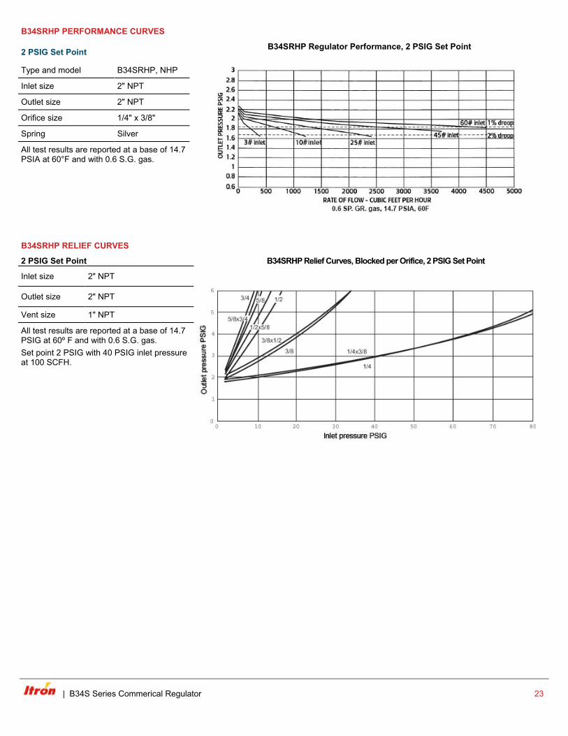
B34SRHP PERFORMANCE CURVES
2 PSIG Set Point B34SRHP Regulator Performance, 2 PSIG Set Point
Type and model B34SRHP, NHP
Inlet size 2" NPT
Outlet size 2" NPT
Orifice size 1/4" x 3/8"
Spring Silver
All test results are reported at a base of 14.7 PSIA at 60°F and with 0.6 S.G. gas.
B34SRHP RELIEF CURVES
2 PSIG Set Point
B34SRHP Relief Curves, Blocked per Orifice, 2 PSIG Set Point
Inlet size 2" NPT
Outlet size 2" NPT
Vent size 1" NPT
All test results are reported at a base of 14.7 PSIG at 60º F and with 0.6 S.G. gas. Set point 2 PSIG with 40 PSIG inlet pressure at 100 SCFH.
| B34S Series Commerical Regulator 23
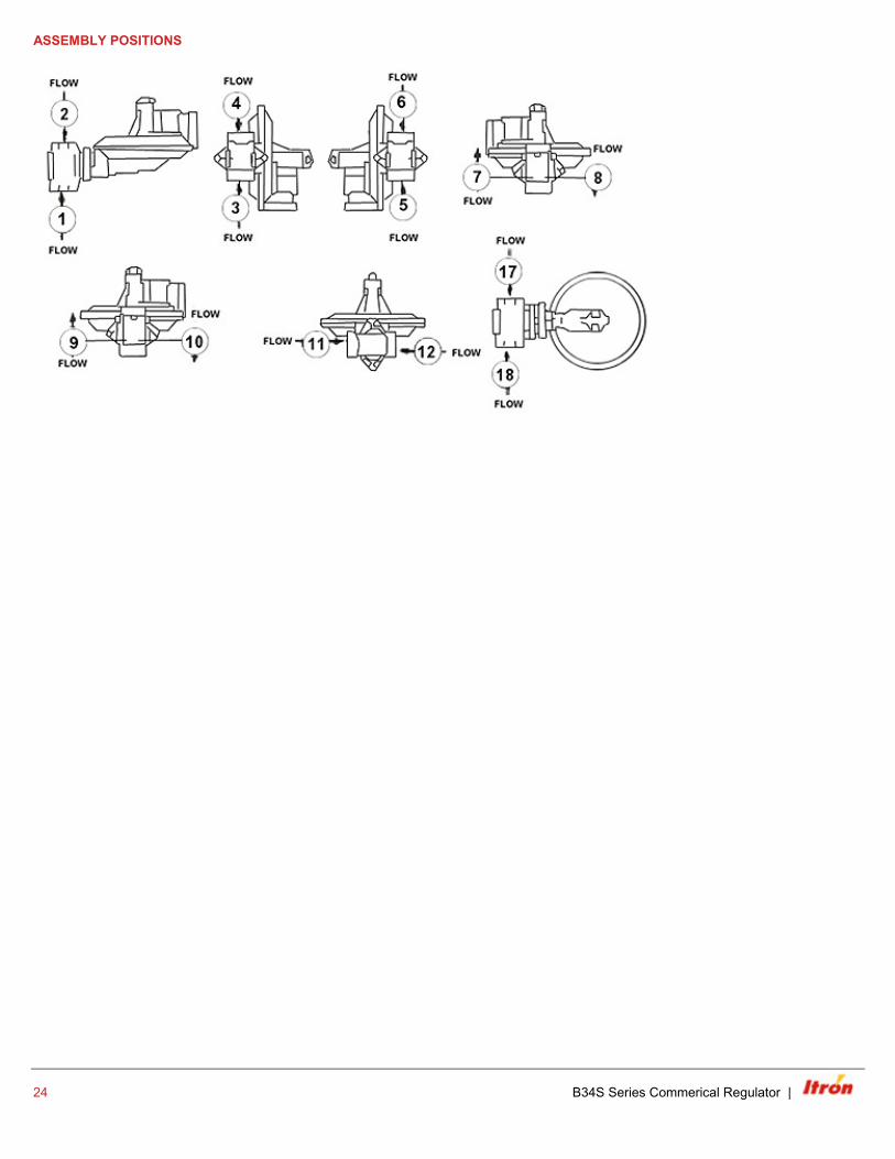
ASSEMBLY POSITIONS
24 B34S Series Commerical Regulator |
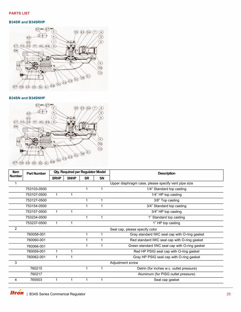
PARTS LIST
B34SR and B34SRHP
B34SN and B34SNHP
Item
Number
Part Number
Qty. Required per Regulator Model
Description SRHP SNHP SR SN
1 Upper diaphragm case, please specify vent pipe size
753103-0500 1 1 1/4” Standard top casting
753107-0500 1 1 1/4” HP top casting
753127-0500 1 1 3/8” Top casting
753154-0500 1 1 3/4” Standard top casting
753157-0500 1 1 3/4" HP top casting
753234-0500 1 1 1” Standard top casting
753237-0500 1 1 1” HP top casting 2 Seal cap, please specify color 760058-001 1 1 Gray standard IWC seal cap with O-ring gasket
760060-001 1 1 Red standard IWC seal cap with O-ring gasket
760066-001 1 1 Green standard IWC seal cap with O-ring gasket
760059-001 1 1 Red HP PSIG seal cap with O-ring gasket
760062-001 1 1 Gray HP PSIG seal cap with O-ring gasket 3 Adjustment screw
760215 1 1 Delrin (for inches w.c. outlet pressure)
760217 Aluminum (for PISG outlet pressure) 4 765503 1 1 1 1 Seal cap gasket
| B34S Series Commerical Regulator 25
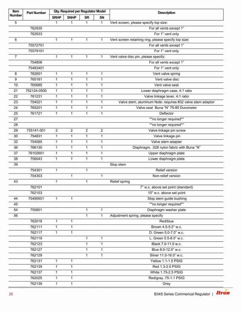
Item Number
Part Number
Qty. Required per Regulator Model
Description SRHP SNHP SR SN
5 1 1 1 1 Vent screen, please specify top size:
762935 For all vents except 1”
762933 For 1” vent only 6 1 1 1 1 Vent screen retaining ring, please specify top size:
75572701 For all vents except 1”
75579101 For 1” vent only 7 1 1 1 1 Vent valve disc pin, please specify:
754806 For all vents except 1”
75483401 For 1” vent only 8 762651 1 1 1 1 Vent valve spring 9 765181 1 1 1 1 Vent valve disc
10 765685 1 1 1 1 Vent valve seat 21 752124-0500 1 1 1 1 Lower diaphragm case, 4:1 ratio 22 761231 1 1 1 1 Valve linkage lever, 4:1 ratio 23 754021 1 1 1 1 Valve stem, aluminum Note: requires #32 valve stem adaptor 24 765201 1 1 1 1 Valve seat Buna “N” 75-85 Durometer 25 761721 1 1 1 1 Deflector 27 **no longer required** 28 **no longer required** 29 755141-001 2 2 2 2 Valve linkage pin screw 30 754831 1 1 1 1 Valve linkage pin 32 754085 1 1 1 1 Valve stem adapter 36 766130 1 1 1 1 Diaphragm, .028 nylon fabric with Buna “N” 37 76102601 1 1 1 1 Upper diaphragm plate 38 756043 1 1 1 1 Lower diaphragm plate 39 Stop stem
754301 1 1 Relief version
754303 1 1 Non-relief version 43 1 1 Relief spring
762101 7” w.c. above set point (standard)
762103 10" w.c. above set point 44 75490601 1 1 Stop stem guide bushing 45 **no longer required** 54 755801 1 1 Diaphragm washer plate 56 1 1 Adjustment spring, please specify
762018 1 1 Red/blue
762111 1 1 Brown 4.5-5.5” w.c.
762117 1 1 D. Green 5.0-7.0” w.c.
762119 1 1 L. Green 5.5-8.0” w.c.
762123 1 1 Black 7.0-11.0 w.c.
762127 1 1 Blue 8.0-12.0” w.c.
762129 1 1 Silver 11.0-16.0” w.c.
762131 1 1 Yellow 1.1-1.5 PSIG
762135 1 1 Red 1.3-2.0 PSIG
762137 1 1 White 1.75-2.5 PSIG
762025 1 1 Red/gray .75-1.1 PSIG
762139 1 1 Gray
26 B34S Series Commerical Regulator |
Item Number
Part Number
Qty. Required per Regulator Model
Description SRHP SNHP SR SN
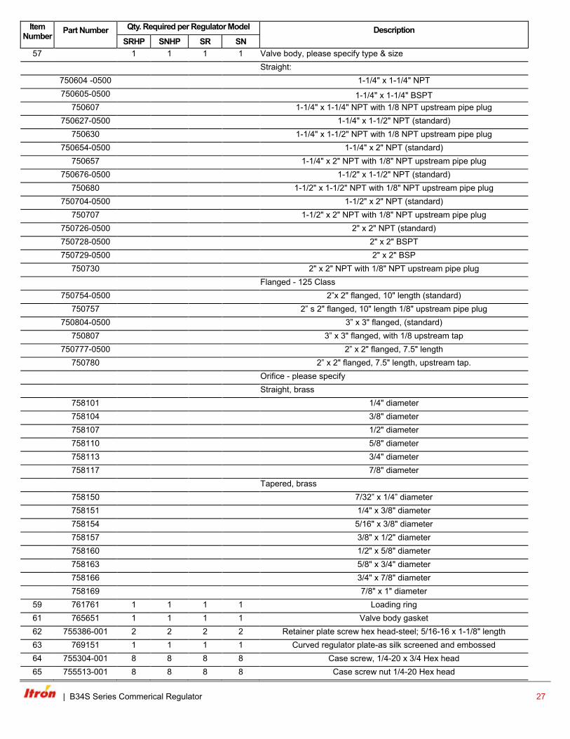
57 1 1 1 1 Valve body, please specify type & size
Straight:
750604 -0500 1-1/4" x 1-1/4" NPT
750605-0500 1-1/4" x 1-1/4" BSPT 750607 1-1/4" x 1-1/4" NPT with 1/8 NPT upstream pipe plug
750627-0500 1-1/4" x 1-1/2" NPT (standard)
750630 1-1/4" x 1-1/2" NPT with 1/8 NPT upstream pipe plug
750654-0500 1-1/4" x 2" NPT (standard)
750657 1-1/4" x 2" NPT with 1/8" NPT upstream pipe plug
750676-0500 1-1/2" x 1-1/2" NPT (standard)
750680 1-1/2" x 1-1/2" NPT with 1/8" NPT upstream pipe plug
750704-0500 1-1/2" x 2" NPT (standard)
750707 1-1/2" x 2" NPT with 1/8" NPT upstream pipe plug
750726-0500 2" x 2" NPT (standard)
750728-0500 2" x 2" BSPT
750729-0500 2" x 2" BSP
750730 2" x 2" NPT with 1/8" NPT upstream pipe plug
Flanged - 125 Class
750754-0500 2”x 2" flanged, 10" length (standard)
750757 2” s 2" flanged, 10" length 1/8" upstream pipe plug
750804-0500 3” x 3" flanged, (standard)
750807 3” x 3" flanged, with 1/8 upstream tap
750777-0500 2” x 2" flanged, 7.5" length
750780 2” x 2" flanged, 7.5" length, upstream tap.
Orifice - please specify
Straight, brass
758101 1/4" diameter
758104 3/8" diameter
758107 1/2" diameter
758110 5/8" diameter
758113 3/4" diameter
758117 7/8" diameter
Tapered, brass
758150 7/32” x 1/4” diameter
758151 1/4" x 3/8" diameter
758154 5/16" x 3/8" diameter
758157 3/8" x 1/2" diameter
758160 1/2" x 5/8" diameter
758163 5/8" x 3/4" diameter
758166 3/4" x 7/8" diameter
758169 7/8" x 1" diameter 59 761761 1 1 1 1 Loading ring 61 765651 1 1 1 1 Valve body gasket 62 755386-001 2 2 2 2 Retainer plate screw hex head-steel; 5/16-16 x 1-1/8" length 63 769151 1 1 1 1 Curved regulator plate-as silk screened and embossed 64 755304-001 8 8 8 8 Case screw, 1/4-20 x 3/4 Hex head 65 755513-001 8 8 8 8 Case screw nut 1/4-20 Hex head
| B34S Series Commerical Regulator 27
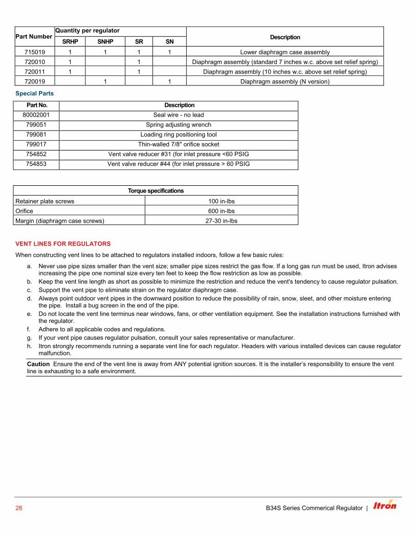
Part Number Quantity per regulator
Description SRHP SNHP SR SN
715019 1 1 1 1 Lower diaphragm case assembly 720010 1 1 Diaphragm assembly (standard 7 inches w.c. above set relief spring) 720011 1 1 Diaphragm assembly (10 inches w.c. above set relief spring) 720019 1 1 Diaphragm assembly (N version)
Special Parts
Part No. Description 80002001 Seal wire - no lead
799051 Spring adjusting wrench 799081 Loading ring positioning tool 799017 Thin-walled 7/8" orifice socket 754852 Vent valve reducer #31 (for inlet pressure <60 PSIG 754853 Vent valve reducer #44 (for inlet pressure > 60 PSIG
Torque specifications Retainer plate screws 100 in-lbs Orifice 600 in-lbs Margin (diaphragm case screws) 27-30 in-lbs
VENT LINES FOR REGULATORS
When constructing vent lines to be attached to regulators installed indoors, follow a few basic rules:
a. Never use pipe sizes smaller than the vent size; smaller pipe sizes restrict the gas flow. If a long gas run must be used, Itron advises increasing the pipe one nominal size every ten feet to keep the flow restriction as low as possible.
b. Keep the vent line length as short as possible to minimize the restriction and reduce the vent's tendency to cause regulator pulsation. c. Support the vent pipe to eliminate strain on the regulator diaphragm case. d. Always point outdoor vent pipes in the downward position to reduce the possibility of rain, snow, sleet, and other moisture entering
the pipe. Install a bug screen in the end of the pipe. e. Do not locate the vent line terminus near windows, fans, or other ventilation equipment. See the installation instructions furnished with
the regulator. f. Adhere to all applicable codes and regulations. g. If your vent pipe causes regulator pulsation, consult your sales representative or manufacturer. h. Itron strongly recommends running a separate vent line for each regulator. Headers with various installed devices can cause regulator
malfunction.
Caution Ensure the end of the vent line is away from ANY potential ignition sources. It is the installer’s responsibility to ensure the vent line is exhausting to a safe environment.
28 B34S Series Commerical Regulator |
INSTALLATION
Warning Itron does not endorse or warrant the completeness or accuracy of any third party regulator installation procedures or practices, unless otherwise provided in writing by Itron. Follow your company's standard operating procedures regarding the use of personal protection equipment (PPE). Adhere to guidelines issued by your company in addition to those given in this document when installing regulators.
a. Remove all shipping plugs from the regulator inlet, outlet, and vent before installation. b. Verify the piping interior and regulator inlet and outlet are clean and free of dirt, pipe dope, and other debris. Dirt and other foreign
materials entering the regulator can cause a loss of pressure control. c. Apply pipe joint sealant to the male pipe threads. Do not use pipe joint material on the regulator's female threads. Joint sealant could
become lodged in the regulator and cause a loss of pressure control. d. Gas must flow through the regulator's valve body in the direction cast on the regulator body. Gas flowing in the wrong direction can
overpressure and cause damage to the regulator. e. The pilot diaphragm casing can be mounted in any position relative to the body through a full 360° angle at 90° increments. f. When the regulator is installed OUTDOORS, the vent must always be positioned so that rain, snow, moisture or foreign particles
cannot enter the vent opening. Itron recommends positioning the pilot vent downward to avoid entry of water or other matter which could interfere with the proper operation of the regulator. The vent should be located away from building eaves, window openings, building air intakes and above the expected snow level at the site. The vent opening should be inspected periodically to insure it does not become blocked by foreign material as outlined in DOT PHMSA-RSPA-2004-19856.
g. When the regulator is installed INDOORS, the vent must be piped to the outside atmosphere using the shortest length of pipe, the fewest possible pipe elbows, and a pipe diameter as large as the vent size or larger. USING VENT PIPE SMALLER THAN THE VENT CONNECTION LIMITS THE REGULATOR’S INTERNAL RELIEF VALVE CAPACITY. The outlet end of the pipe must be protected from moisture and the entrance of foreign particles. The regulator should be specified by the user with the size vent and pipe threads desired to make the vent pipe connection.
START-UP PROCEDURE
a. Mount a pressure gauge downstream of the regulator to monitor the downstream pressure. b. With the downstream pressure valve closed, slowly open the inlet valve. The outlet pressure should rise to slightly more than the set-
point. Verify there are no leaks and all connections are tight. c. The regulator was pre-set at the factory to match order specifications. If necessary, adjust the outlet pressure by removing the seal
cap on the top of the pilot spring housing and adjusting the ferrule or screw inside the pilot spring housing using a large flat-head screwdriver. With a small amount of gas flowing through the regulator, rotate the pilot ferrule clockwise to raise the outlet pressure or counter-clockwise to lower the outlet pressure.
d. Replace the seal cap and check for leaks after the desired outlet pressure is achieved.
The regulator is ready for operation.
SAFETY WARNING
This product, as of the date of manufacture, is designed and tested to conform to all governmental and industry safety standards as they may apply to the manufacturer. The purchaser/user of this product must comply with all fire control, building codes, and other safety regulations governing the application, installation, operation, and general use of this regulator to avoid leaking gas hazards resulting from improper installation, startup or use of this product.
Itron strongly recommends installation by a qualified professional and periodic inspection of pressure regulators (inspections may be required by local applicable codes or regulations).
Inspections should include checking for gas quality, cycle numbers, external environmental changes, and operating conditions that impact wear on the regulator's moving parts. To ensure safe and efficient operation of this product, replace worn or damaged parts found during inspection.
| B34S Series Commerical Regulator 29
LIMITED WARRANTY
Itron, Inc. 970 Highway 127 North, Owenton, Kentucky 40359-9302, warrants this gas product against defects in materials and workmanship for the earlier of one (1) year from the date the product is shipped by Itron or a period of one year from the date the product is installed by Itron at the original purchaser’s site. During such one-year period, provided that the original purchaser continues to own the product, Itron will, at its sole option, repair any defects, replace the product or repay the purchase price.
» This warranty will be void if the purchaser fails to observe the procedures for installation, operation or service of the product as set forth in the Operating Manual and Specifi cations for the product or if the defect is caused by tampering, physical abuse or misuse of the product.
» ITRON SPECIFICALLY DISCLAIMS ALL IMPLIED WARRANTIES INCLUDING THOSE OF MERCHANTABILITY OR OF FITNESS FOR A PARTICULAR PURPOSE. UNDER NO CIRCUMSTANCES WILL ITRON BE LIABLE FOR INCIDENTAL OR CONSEQUENTIAL DAMAGES OF ANY KIND WHATSOEVER.
» Itron’s liability for any claim of any kind, including negligence and breach of warranty for the sale and use of any product covered by or furnished, shall in no case exceed the price allocable to the product or part thereof which gives rise to the claim.
» In the event of a malfunction of the product, consult your Itron Service Representative or Itron Inc., 970 Highway 127 North, Owenton, Kentucky 40359-9302. See Itron Terms and Conditions of Sale for the full and complete terms of the Limited Warranty.
ORDERING INFORMATION
Specify:
1. Inlet and outlet connection size and type
2. Model number
3. Outlet pressure desired
4. Pilot needed
5. Inlet pressure range
6. Type of gas and maximum capacity required
7. Assembly position number (see chart above)
8. Special requirements such as tagging, 1/8" pipe plug tap, seal wire, etc.
While Itron strives to make the content of its marketing materials as timely and accurate as possible, Itron makes no claims, promises, or guarantees about the accuracy, completeness, or adequacy of, and expressly disclaims liability for errors and omissions in, such materials. No warranty of any kind, implied, expressed, or statutory, including but not limited to the warranties of non-infringement of third party rights, title, merchantability, and fi tness for a particular purpose, is given with respect to the content of these marketing materials. © Copyright 2017 Itron. All rights reserved. 101063SP-06 10/17
Join us in creating a more resourceful world.To learn more visit itron.com
CORPORATE HQ2111 North Molter RoadLiberty Lake, WA 99019 USA
Phone: 1.800.635.5461Fax: 1.509.891.3355