B AD-A149 470 AD - apps.dtic.mil · way, as in a rocket motor or a. liquid gun propellant. The rate...
86
AD B AD-A149 470 R CONTRACT REPORT BRL-CR-537 L L1 A REVIEW OF HAZARD ASSESSMENT PROCEDURES FOR LIQUID GUN PROPELLANTS Prepared by University of Arkansas Fayetteville, Arkansas 72701 November 1984. DTIC .; .JAN 2 3 .10 APPROVED FOR PUaUC MUM.S,,DISMOUTIU~ON UNUMITMO • '= " IUS'ARMY. BALLISTIC RESEARCH LABORATORY :"""I .AFERDEEN PROVING 'GROUND, MARYLAND 0 . IC REL COPY 85 01 15 096 - -. __% . . . . .' ...
Transcript of B AD-A149 470 AD - apps.dtic.mil · way, as in a rocket motor or a. liquid gun propellant. The rate...

ADB AD-A149 470
R CONTRACT REPORT BRL-CR-537
L L1
A REVIEW OF HAZARD ASSESSMENTPROCEDURES FOR LIQUID GUN PROPELLANTS
Prepared byUniversity of Arkansas
Fayetteville, Arkansas 72701
November 1984. DTIC.; .JAN 2 3 .10
APPROVED FOR PUaUC MUM.S,,DISMOUTIU~ON UNUMITMO
• '= " IUS'ARMY. BALLISTIC RESEARCH LABORATORY:"""I .AFERDEEN PROVING 'GROUND, MARYLAND0
. IC REL COPY85 01 15 096
--. __% . . . . .' ...

/
.0/
Destroy this report when it is no longer needed.Do not return it to the originator.
Additional copies of this report may be obtainedfrom the National Technical Information Service,U. S. Department of Commerce, Springfield, Virginia22161.
/•ii
The tindings in this report are not to be construed as an official-Department of the Army position, unless so designated by otherauthorized documents,
The use of trade names or manufacturers' names in this report"does not constitute indorsement of any commercial product.
') 'I

-- UNCLASSIFIED"SECURITY CLASSIFICATION OF THIS PAGE (W•aln Data ,ntwed)
SREPORT DOCUMENTATION PAGE READ INSTRUCTIONSRE R DBEFORE COMPLETING FORM
I. REPORT NUMBER 2. GOVT ACCESSION NO 3. RECIPIENTS CATALOG NUMBER
CONTRACT REPORT BRL-CR-537 26•/OV A 7 Nc 3. _RC _P __TSCATAOGNMBE
4. TITLE (and Subtitle) s. TYPE OF REPORT & PERIOD COVERED
A Review of Hazard Assessment Procedures for• [ Liquid Gun Propellants_
Lu G o a.n PERFORMING ORG. REPORT NUMBER
7. AUTHOMR() S. CONTRACT OR GRANT NUMSER(.)
Jerry A. Havens DMD05 82 MD 202"9. PERFORMING ORGANIZATION NAME AND AOORESS 10. PROGRAM ELEMENT. PROJECT. TASK
AREA & WORK UNIT NUMBERS
"University of ArkansasFayetteville, Arkansas 72701 1L162618AH80
11. CONTROLLING OFFICE NAME AND ADDRESS 12. REPORT DATE
US Army Ballistic Research Laboratory November 1984ATTN: AHXBR-OD-ST Is. NUMBER OF PAGESAberdeen Proving Ground, MD 21005-5066 84
14. MONITORING AGENCY MAN II AODRKSW(I difle~renui km ConfroiUnd Ofice) 15. SECURITY CLASS. (of this report)
Unclassified•. . AsLASSI FICATION/DOWNGRADING
SCHEDULE
16. DISTRIBUTION STATEMENT (*1 Ole Reom)
' Approved for public release; distribution is unlimited.
17. DISTRIUUTION STATEMENT (of the abstract ewed in Blae.k I0t different *m Rapis)
IL. SUPPLEMENTARY NOTES
IS. KEY WORDS (Cont/hhe an tieie,eedside iteneessary ie Nealy by block umozer)
Hazard testing, safety testing, sensitivity tests, liquid propellants
26L AUSTIRACT tCtaME -WF onowro mE1 Massis eUtbyb anII 0661kmoba"
Safety. testing procedures for energetic liquids are reviewed. Arationale for development of a protocol for safety testing of liquid gun"propellants is suggested. A compilation of safety test data for gunpropellants, along with comparison data for explosives and rocket propellants,is predented. Applicabtlity of test methods developed primarily forexplosives and high energy rocket propellants to the assessment of hazards
S-' "that may be encountered in handling, storage, and transportation of gun
""D I 1413 uo V UNCLASSIFIED
'SecumTV CLAMSFICA1IOW (P We*S PAe 620e. at

-I IUNCLASSIFIED"SECURITY CLASSIFICATION OF THWS PAGE(Whanm DAMa ntOMeQ
20. ABSTRACT (Cont'd):
propellants is considered. Test procedures which should be further evaluated"are identified. In general, the data available on the response of liquid gunpropellants to these test procedures are not sufficient for a thorough"evaluation of the teats' usefulness for assessing liquid gun propellanthazards. Additional work is recommended to provide test data which can beused to compare the response of gun propellants with other energetic liquidsfor which there is an extensive safety experience data base. Further work is
--'also recommen&.d to characterize the energy input and boundary conditions for"the selected .est procedures to provide a means for evaluating the tests withrespect to severity and correspondence to conditions which may be encounteredin handling, storage, and transportation.
UNCLASS1flESeculIV C11ASWiiAit"Of you 001041019101 Dm Z;; Iaý*
-.-
-. I--

I/
TABLE' OF CONTENTS
Page
LIST OF ILLUSTRATIONS ..................................
LIST OF TABLES ............................. • .. .... 71 . I N T R O D U C T I O N .. . . .. . . .
I1. SAFETY TESTING OF LIQUID MATERIALS FOR POTENTIAL EXPLOSIVEHAZARD*............. .o..........ee..ee.eoooeoeeoeooe.e..eooeee..........9
A. Thermal Energy Input Tests ......... .......... ......
1. Ignition T.eaue12. Flash Point .......T... 12
3. Differential Thermal Analysis.......... .0.000 ............ 13
4. Thermal Surge ... Tes...... ........... .................... .. 13
5. Thermal Stability ......... ty.... ................. 8~~~. Impact Energy Input Tss......... .............
: ~1. Drop egt1
S~~~~~~2. Adiabatic Compre~sion Sensitivity,*.*..... ...... .l
3. Compression-Ignition Sensitivity of Liquid GunPropellants at Gud Operating Conditlons................Z.1
4.' Other Low Amplitude Compression Wave.Tests ................ 22
C. Shock Energy Input Tests......................................25
1. Card Gap .25
2. Impedance Mirror.... ...............
3. Shock-Confinement Tests . . . . . .
0 0. Comparison of Test Parameters and Correlation ofTest Results .....
1. Initial State of the Sample Material,.................33
2. Energy Transfer from Explosive Donor.............,........36
3. Boundary Conditions Imposed by Container...................36
4. Low Velocity Detonation (LVD) ........... 41
II1. SUMMARY OF REVIEWED WORK PERTAINIHG TO SAFETY EVALUATION OFLIQUID GUN PROPELLANTSr........... .... ........... ........... 044
A. Thermal Energy Input Tests............,........ . .
1. Ignition re......................................442. FlashPon.......................4
3. Differontial Thermal Analysis.............................45
3
... .. . . . - -• -.. .. . •..~ . ',- .* , • . • o . , . . ' . . . • . • - • .
* * .. . .* .-* . .* * .- * * . - . . 9 . * * •t *~ o o. s

TABLE OF CONTENTS (continued)
Page
4. Thermal Surge ...................................
5. Thermal Stabil ity .. .. *g.a 46B. Impact Sensitivity Tests ...................................... 48
1. Drop Weight ........i 2. Adiabatic Compression
3. Compression-Ignition Sensitivity Measurements atGun Operating Conditions ........ .. 50
4. Other Low-Amplitude Compression Wave Tests................56
C. Shock Sensitivity Tests ....................................... 571 1. Card Gap..................... . ...... ,,.. .... ...... 512. Impedance Mi ........ 60.......... . . . . ." . .603. Heavy Confinement Shock Tests ...... ...................... 61
0. Miscellaneous Tests ............................................. 61| I~~~1 Cap Sniiiy"6
" 2. Trauzl Block .....
3. Bullet Impact ..................
4. Bonfire and Unconfined Burning ...... . . ......... 67
IV. DISCUSSION AND RECOMMENDATIONS ................................. ... 68
REFERENCES....O ........................
GLOSSARY .. o............. . ............... .... .0.7
DISTRIBUTIONLIT 8
I
I
I
j

LIST OF ILLUSTRATIONS
,Figure Page
II-1. Typical Thermal Surge Test Results ...... ... ........... 14
11-2. Drop Weight Test Apparatus ....... ................. 16
11-3. Sample Volume Dependence - Drop Weight Test of NPN . . .... 17
11-4. Effect of Subjective Nature of Test Criteria - DropWeight Test . . ......... .................... ... 20
11-5. Schematic Diagram Adiabatic Compression Test ....... ..... 20
11-6. Bubble Volume Dependence -'Adiabatic Compression Testof NPN ..... ........... I . ................ ... 21
11-7. Low Amplitude'Compression Wave Impact Test ........... ... 23
11-8. Naval Ordnance Laboratory Card Gap Test ... .......... ... 27
11-9. Bureau of Mines Instrumented Card Gap Test ......... 28
11-10. Impedance Mirror Test Arrangement ..... ............ . 30
II-li. Bureau of Mines Confinement Test........ . ...... ... 32
II-i2. Confinement Test Results - Benzene/Nitromethane Mixtures . 32
11-13. Effect of Temperature on Card Gap Test Results . . . . . . . 34
11-14. Apparatus for Studying the Initiation of LiquidExplosives Containing Gas Bubbles ...... ............ 35
1l-IS. Effect of Explosive Donor Strength on NOL Card Gap Test
for NM..... ..... ... ..... ....... ... . 37
11-16. Peak Pressure vs. Gap Thickness for NOL Card Gap Test . . . 38
II-17. Bureau of'Mines Test Apparatus for LVD/HVD ThresholdDetermination........ ..... . . . . . . . . . . . . . 42
11-18. HVD/LVD Threshold Gap Values for 50/IO NG-EGDN inDifferent Acceptor Containers ........... ....... 43
5

LIST OF ILLUSTRATIONS (continue4.
Figure Page
III-1. General Electric Slow Fill Compression IgnitionSensitivity Apparatus ...... ................... 51
111-2. General Electric Rapid Fill Compression IgnitionSensitivity Apparatus ............. . . ........ 53
111-3. Princeton Combustion Laboratories Compression-Ignition Sensitivity Apparatus ....... ........... . 54
111-4. Domain of Safe Operation for Avoidance of RunawayReaction Due to Compression-Ignition of NOS-365 ..... SS
111-5. Domain of Safe Operation for Avoidance of RunawayReaction Due to Compression-Ignition of LGP-1845 . ... 56,
111-6. Tube Test Fragments of Mild Steel fromDetonation of NOS-365 . ... ......... . . 62
111-7. Tube Test Fragments of Mild Steel fromDetonating 13 Molar HAN'Solution ..6..... ... ... ... 62
111-8. Section of 20 mm Mann Barrel-Used in NOS-365 Test . 63
111-9. 20 mm Mann Barrel Fragments from Tests on NMand Composition C-4 ....... ................... 64
I!I-10. Confinement Test Results for OTTO-I .... . .. ........ 665
',

LIST OF TABLES
Table Page
I1-1. Typical Drop Weight Test Results. .. .. .. ... ..... ........ 17
11-2. Selected Drop Weight Test Results for Liquid!mnopropellants I. . . . .................................................. 18
11-3. Drop Weight Test Results for OTTO-Il Monopropellant 1
11-4.- Adiabatic Compression Sensitivity Test Res;ults forLiquids Reported by Mead .. .. .. .... ..... ..... ....... 22
11-5. Selected Adiabatic Compression Sensitivity Test Resultsfor Liquid Monopropellants. .. .. ..... ..... ..... ...... 22
11-6. Low Amiplitude Compression Wave Test Data. .. .. .. ... .... ....24
11-7. Specifications for Bureau of Mines Card Gap Test .. ...... 26
11-8. Selected Bureau of Mines Instrumented Card Gap 2Test Results 29.. . . .. . . . .
11-9. Effect of Acceptor Ccntainer Geometry on Card GapTest Results for SO/SO NG-EGDN at 2S0C . . . . . . . . 39
11-10. Effect of Acceptor Container and Wall ThicknessC(Gon-finement) on Card Gap Test Results. .. .. .. ... . ....
RE: Classified References* DistributionUnlimiited a*50FoNo change per Mr. Arola, Ballistic Res. Lab. al
DTICi~ELECTE uln
JAN-2 39085 ' . lab1ilt.T C~d08
7

LIST OF TABLES (continued)
Table Page
III-!. Autoignition Temperatures ...... .................. 44
111-2. Flash Point (Open (lip) Temperatures .............. . . 45
111-3. Differential Thermal Analysis Data ................... 45
111-4. Thermal Surge Test Data . . . .... . . . . .. . ... . 46
111-5. JANAF Thermal Stability Test Results 47
111-6. "Long Term"Thermal Stability Test Results ........... . ... 47
111-7. Thermal Stability Scan Test Results ... ............ 48
111-8. Drop Weight Test Data ....... ................... 49
111-9. Adiabatic Compression Test Data .... ....... .......... 50
III-10. Low Amplitude Compression Wave Test Data.. .. .. S7
Ill-11. Card Gap Test Data for Potential Liquid Gun Propellants 58
111-12. Pulsepower Systems Inc. Card Gap Test Summary . . . .. ... 5
111-13. Detonation Velocity Test Results ... ........... .. 60
111-14. Reaction Times Measired with the Impedance Mirror Test 61
11l-15 Trauzl Block Test Results .......... . . . . . ... .S
111-16. Bullet Impact Test Data .......... .. . .6..
IV-I. Selected Test Pesults for Liquid Gun Propellants . • • . • 70
IV -2. Sensitivity Order of Test Results from Table TV-I ....... 71
8
": : • •: " .'-'" . " ' '""". .•- " " "" .'' " '.;.; " $""'' F'. '"."•.-.., .. .• " '"•
, a, • • • • .• • , . , • o . . w, • . s•• . * m q *A * * . '

I. INTRODUCTION
Liquid gun propellant evaluation programs are developing requirementsfor candidate test propellants in larger than laboratory-scale quantities.Methodology is needed for assessmentof hazards that may be encountered inhandling, storage, transpertation, ard end use.' There are numerous testprocedures applicable to liquid gun propellant safety testing, but it can-not be assumed a priori that procedures developed for other, classes ofmaterials (eig., rocket propellants or explosives) are equally applicableto liquid gun propellants. For example, a test procedure developed toquantify the shock sensitivity of high energy rocket propellants may notidentify a lhwer, but nevertheless important, degree of shock sensitivityof a candidate liquid gun propellant.
The purpose of this work was to make an initial assessment of thehazardcus material safety testing procedures that have been applied to ener-getic liquids and to provide recommendations for additional test require-ments which may be indicated for assessing liquid gun propellant hazards.Three subordinate tasks were involved. First, a review of selected classi-fied literature relating to liquid gun propellent development and testingwas conducted at the U.S. Army Ballistic Research Laboratory. Second, a,limited review was made of the published scientific literature in pertinentareas, particularly in detonation physics. Third, visits were made toselected government and private organizoetions involved in the developmentand testing of liquid gun propellants. These visits were -for the purposeof discussing unpublished and on-going work pertaining to safety testing ofliquid gun propellants..
In Part II a discussion of tests which have been used to assess hazardsof energetic liquids is presented. Emphasis is placed on test proceduresthat are thought to be of highest priority for evaluation. Test methodology,typical test results, observations of test variability, and test inter-pretation are discussed. Part III is a summary of test results reviewedwhich pertain to hazard evaluation of liquid gun propellants. In Part IVthe reported test results are discussed and'recommendations are made forfutu're test programs.
II. SAFETY TESTING OF LIQUID MATERIALS FOR POTENTIAL EXPLOSIVE HAZARD
'The utility of explosives and propellants derives from their potentialfor rapid chemical reaction with attendant energy release'. A propel"- nt(in contrast to an explosive) is, designed to release energy in a controlledway, as in a rocket motor or a. liquid gun propellant. The rate of energyrelease for A chemical reaction depends on external conditions as well asthe chemical structure of the material. Hence, a propellant may, underconditions different' from those of its intended use, release energy at arate sufficient to cause destruction. Materials useful as gun propellantsare a case in point.
The "safety" of any potentially explosive material, relates to itspropensity for uncontrolled burning or explosion resulting from exter-rally imposed conditions. Such a definition of the term "safe" extends
",' o-~~ ~~~~~ .... °° °o ° '. . ~ • •••.."............

beyond the actual propellant application conditVons in a gun to storage,handling,and transportation. The material should exhibit highly repeatableburning characteristics under design usage conditions but should not react
.violently in. response to external stimuli from handling, storage, and trans-portation. Ideally, it shouldnot react violently even to external con-ditions which may-arise under abnormal conditions, such as accidents. Inthis regard, safety requirements imposed for propellant (and explosives)handling, storage and transportation inevitably involve compromises. Itcannot reasonably be expected that such materials can exhibit all of thedesired in-use features (for example, ease of ignition in use) and all ofthe desired safety features (for example, relative difficulty of ignitionunder all accident conditions).
However, the in-use and safety requirements of-propellants and explosivesare not mutually exclusive. The development of commercial explosives totheir present status affirms this fact. Furthermore, the logic to befollowed in selection of propellant materials which perform as desired inuse, yet are safe, is deceptively simple:
1. Characterize the conditions imposed on the material in use, forexample, in a gun..
2. Characterize the conditions which may be imposed on the materialin handling, storage,.and transportation.
3. Characterize the reaction proces., of the material as a function of-the'conditions identified in'steps 1 and 2.
4. Select a material that satisfies the performance criteria of thegun but does not react violently to the conditions of handling, storage,and transportation (and to the extent possible to conditions resulting fromaccidents in handling,.storage, and transportation).
The present process of selection of candidate materials for use aspropellants does not follow this recipe, for the following reasons:
1. Actual performance (e.g., gun performance) cannot be completelypredicted, again due primarily'to our inability to predict propellant burningcharacteristics under ,gun ,operating conditions. The approach is to test thematerial under actual firing conditions to ascertain performance andsafety.
2. We are not ablle to specify accurately the conditions that may beimposed on a material during normal'handling, storage, and transportation:and we know less about the conditions that'm'y be encountered in accidents.The approach is usually to subject the material to external energy/inputswhichare considered to be at'least as "severe" as-those expected inhandling, storage, and transportation.
In general, the safety criteria for a'propellant material relatedirectly to the response of the material to inputs of energy. Such inputsof energy, although theoretically reducible to a common thermal energy input
10
. ... " .• .-. , .,' ................-...................... . ,•. . . . .... .. "". ." " " . . . . . . . . . . . . ..."" """" . . '.. "-"". ....... .....'.."- , "' ..- '•i.. '.-.., . .

4basis, are usually (somewhat arbitrarily) classified in separate categoriesas follows:
1. Thermal input (heat transferred into material);
2. Impact energy input;.
"3. Shock energy input;
4. Electrical discharge energy input.
In this literature review, emphasis was placed on the first three"*] hazard evaluation categories listed above. No references were found on
direct electrical discharge energy input measurements on liquid gun pro-"pellants, except data obtained in gun performance ignition studies.
, The last three energy input categories can all be considered as formsof work-energy inputs (in the thermodynamic sense) which are convertedlocally in the material to thermal energy. The quantitative description ofthe conversion of such work-energy inputs to thermal energy is the provinceof irreversible thermodynamics; we do not as yet know how to compare thedifferent types of energy inputs on a common basis. Hence,a test protocolusually includes multiple test procedures to determine the response of
4 materials to each of these categories of input 'energy.
A. Thermal Energy I.iput Tests
This type of test may be directed to the ease of ignition of volatilesmproduced by the material or to the material's stability at increased tem-perature. In ignition tests, which are primarily directed to det ermina-tion of fire hazard, the temperature of the material is determined at
* which it produces wlatiles sufficient to allow piloted ignition in the gasphase above the material, or at which the material (or its gaseous products)spontaneously ignites.' Thermal stability tests are usually directed to'"the determination of the maximum temperature below which the material doesnot generate reaction heat at a rate greater than that which can be trans-ferred to the surroundi'ngs. If this temperature is exceeded for a material-
*.' which can undergo an'exothermic reaction,' the temperature will increaseuncontrollably and a "thermal explosion" will result.
Thermal EWplosion Theory, introduced by Semenov and Frank-"Kamenetskii,' provides a rationale for understanding and correlation of"the response of energetic materials to thermal stimulili. Application ofthe energy balance principle to a homogeneous, isotropic, heat-generatingmaterial in which heat transfer is limited to conduction gives the dif-ferential equation for the temperature distribution in the material as afunction of time:
4.H. NN. Semenov, ChamLhn) JIt , i'•frA a.d Chln Raotli,, Ox6o-d UniveA-"ta, P,'te,4, London (1935).
2. V. A. F~auik-Kamene~tskii, DJ~AiitAIn 'l md Hy"n Fv,4nampg, h C1,pmleff4 ig- Pi.Z inceon-Univmay~ Pxaz~, P4Zneeton, NJ (1955).
411
I

* pCL-= XV2T + pQ1)dtT+ Q
""" Energy Energy Energy (Thermal)Accumulation = Transfer + ProductionRate Rate (Net) Rate
where T = local temperaturet = ti.me"p = local densityC = local heat capacity"X = local thermal conductivityQ = thermal energy production rate per unit mass (from
chemical reaction)
The general solution to this second order partial differential equationinvolves two arbitrary constants whose values depend on the initial andboundary conditions imposed on the material. Because of the dependence ofthe temperature on such boundary conditions, the temperature at which amaterial can dispose of the heat produced internally from chemical reactionas fast as it is being produced is not a unique value. This temperaturedepends on the transport properties of the material and on the. boundaryconditions (primarily heat transfer boundary conditions). Consequentlythermal stability values (temperatures) obtained by different experimentaltechniques may not be directly comparable. In principle, the effect ofnon-thermal energy inputs into a material, to be discussed subsequently,can al'so be treated vig tha thermal explosion theory if the conversion rateof such energy inputs ti thermal energy can be quantified. Unfortunately,information in this er- most totally lacking.
There are a large , '.;ber of test procedures which have been used to.,estimate "safe handlir-;,storage" temperatures. As a class they are simi-
lar in that thermal energy is transferred to the material at a specifiedrate and the temperature at which the material gives evidence of reactionis noted. The rate of heat input varies greatly with the test. proredure.A literature search evealed four sources of data for response: of- liquidgun propellants to c ntrolled thermal energy inputs. These data werederived from conventional flash-point and ignition temperature tests"and differential the 1 I analyses, from "thermal surge" tests developed"at the Naval Ordnanc Laboratory, and from variations of the "thermal
Sstability" tests dev loped by the Interagency Chemical Rocket- PropulsionGroup. (ICRPG). Some data on the response of contalherized materials tof fire exposure, refered to as "bonfire" tests, are also noted, althoughthey are considered f little value for quantitative evaluaticn purposes.
"* These test procedure will be described briefly.
1.. I.gIjnition Tenperature. The objective of this test is the deter-mination lowest temperature -at which vapors from the material willspontaneously ignite in air. The result can be expected to depend ongeometry of the vapor/air mixture sample even for a homogeneous gas/airmixture. The (Setchkin)Autoignition Temperature Test, standardized as
'i ~12 '
I-:-

ASTM D286-36, has been widely applied to this type of measurement fora large number of materials. The experimental apparatus consists of a one-liter spherical flask maintained at a constant temperature. A liquidsample is injected into the flask and the time to ignition (determined bythe appearance of a flash) is recorded. The test is repeated at higherand/or lower temperatures, as indicated; and the ignition time is deter-mined as a function of temperature. The (extrapolated) temperature atwhich the ignition time becomes "infinite" is the autoignition tempera-ture. Although an initial sample size of 0.05 ml (liquid) is usually pre-scribed, tests are repeated for different sample volumes to determinethe minimum value of the ignition temperature.
2. Flash Point. The objective of the flash point test is the deter-mination of the lowest temperature at which the material evaporates rapidlyenough to form a flammable vapc-/air mixture over the liquid surface.Because the formation of a flammable mixture in the vapor space depends onthe evaporation of the liquid and its subsequent mixing with air, the testresult is expected to be dependent on the sample and test chamber geometry.Methods have been standardized for open and closed container test pro-cedures (ASTM 92-72 Cleveland Open Cup Flash Point Test and ASTMTAG Closed Cup Flash Point Test). In either case a small pilot flame ispassed over the liquid surface, or at a designated opening where the samplevapors exit, at intervals of increasing temperature. The lowest liquidtemperature at which the application of the pilot flame causes the vaporsabove the surface of the liquid to ignite is taken as the flash point.
3. Differential Thermal Analysis (DTA). This technique is based onmeasurement of the difference of internal energies, or heat contents,between an inert reference material and the sample material when both areheated in a similar thermal environment. Usually, the two materials aresimultaneously exposed to a thermal environment which produces a lineartemperature increase of the reference material. Due to the limitations(difficulties) in achieving accurate and reproducible high rates of heattransfer to the test sample in conventional OTA'apparatus, sample tempera-ture increase rates are typically low, i.e. less than 40*C/min. Differen-tial thermal analysis measurements of the temperature at which an exo-thermic reaction is first observed is indicative of the thermal stabilityof the material.
4. Thermal Surge. This test procedure, developed at the NavalOrdnance Laboratory, is designed to determine the response of small, highlyconfined samples to very rapid heating-(lsec to a few msec) to temperaturesto 10000C. A 2.1 pL sample is enclosed in a 6.35-cm length of stainlesssteel hypodermic needle tubing. The tubing is heated very rapidly by dis-'charging a capacitor through it, and its resistance is measured as a func-tion of time. The temperature of the tubing is determined from separatemeasurements of its resistance at different known temperatures. Explosionof the sample is evidenced by an abrupt change in the electrical resistancewhen the tube wall bursts. Hence the temperature of the'sample containerand the delay time before explosion are determined by measuring the resis-tance of the hypodermic needle tubing as a'function of time. The delaytime to explosion is measured with an electronic timer which is started by
13

a signal from the capacitor discharge and stopped by a signal from a nicro-phone located near tqe bursting sample tube. The apparatus is describedby Kendall and Rosenj and Wenoorad.4 Typical data presented as plots ofdelay time to explosion against reciprocal temperature are shown inFigure 1l-1 from Kendall and Rosen and Stull.: The delay time can berelated to, frequency factors and activation energies for describing thereaction kinetics and is a measure of the rate of reaction (rate of energyrelease) and hence, sensitivity of the material to intense thermal energyinput.
/NMo(4) NPN
(4); h ~1.0 N
z0
i.•i
0
:J0~
0.Ui
-0.05-mo
:"I I I " I' '
.08 1.0 1.2 1.4 1.6 1.8
.TEMPERATURE, (IO0/TOK)
*.. Figure II-I. Typical Thermal Surge Test Results3 ' 5
3. P. A.' KendatU ard .1. MA. R6e~n,'¶rhe.'vat Ini~tidtwo Appautui~ 6ox HighEne.'Egy Atioat•• "R,'eview o SeiantLix e Ih•tAt•me"uA, 7, pp. 992-994, Juty 1968.
4. .J. Wenogyad, TIAnnAjactinUA Fau~rda Sohlp , 57, p. 1612, (1961).5. V. R. St.uZZ, "Fundamen~ta& o6~ FiAe and Exp~oZon, 'I.i~hE &noo"fA~
Sij. 10, 73 (1977).
"14
%

4
5. Thermal Stability. The JANAF thermal stability test is the stan-• -dard test designed by the ICRPG for testing thermal sensitivity (stability)"of propellants. The apparatus consists of a stainless steel cylinder 0.22
inches in diameter by 1.5 inches length clos.d at one end with a feed-"" through for a shielded thermocouple. A 0.5 cc (liquid) sample is placed
in the cylindrical cavity and the top is sealed with a stainless steel dia-phragm 0.003 inches thick. The sample container is placed in a temDeraturecontrolled bath which increases at 10C/minute. The temperature differencebetween the sample (TS) and the bath (TB) is monitored,and temperatures at"whici thermal activity of the sample (positive TS - TB for exothermicreaction and negative for endothermic reaction) are observed are reported.
Isothermal tests are also used to indicate thermal stability. Althoughthere have been severai variations on this procedure reported, they aresimilar in that a sample is placed in a container which is then placed in acontrolled temperature bath. The sample temperature (and pressure in someprocedures) is monitored for 'a designated test period, which can be ofseveral days duration. Excursions in temperature or pressure in the samplecontainer are reported as indications of heat of reaction effects.
B. Impact Energy Input Tests
Impact test procedures are designed to simulate rapid compression* which may result from mechanical impact directly on the propellant,
indirectly on its 'container, or by adjacent liquid propellant (as in apumping system). Si'nce compression of gases or vapors results in muchhigher temperatures than for liquids, most impact test procedures used forevaluation of liquids incorporate gas (or vapor) bubbles in contact withthe liquid fuel. The bubble in contact with the fuel is rapidly compressedby means of a free-falling or gas-driven piston. The minimum energy per"unit of bubble volume required to initiate observable combustion in thesample is considered a measure of the material's sensitivity to impactinitiation.
Thermal explosion theory indicates that impact energy input testresults should be dependent on the initial and boundary conditions towhich the sample is subjected. Consequently, results from the severalimpact test procedures, which differ in sample and containment geometryand type of mechanical impetus applied, must be compared with caution.
Two test procedures have been widely used for impact sensitivitytesting of energetic liquids. The Drop Weight test recommended by the,Interagency Chemical Rocket Propulsion Group (ICRPG) and identified as"test No. 40 by the Chemical Propulsion Information Agency (CPIA) is now"standardized as ASTM D2540-70, Standard Method of Test for .Drop Weight
6
6. Te~t No. 4, "V.op Weight Test," Liqui.d P'opellant TeAt Me~thod6, Lqui.dP•.opetant In~oima•on Agency, The John6 Hopkt.b. Uni.ve.,'t,4, SitveASping, MR (now CPIA, Lautet., MD) , Vece.ibeA 1959.
-".,. * , s * ,~ ,
* • * . ... - . - • . ". , .; " " ' " . ."" " -" "," "," ," ," , ."."-
Sensitivity- of Liquid Monopropellants. The adiabatic comrnression testrecommended by ICRPG and identified by CPIA as test no. 5' is also describedby Mead. 8
1. Drop Weight. A 0.03 mL sample of the liquid is enclosed in acavity (0.06 mL) formed by a steel cup, an elastic ring, and a steel dia-phragm, as shown in Figure 11-2. The sample is placed in the steel cupwhich has an AN 6227B-5 O-ring seated in the bottom. The diaphragm isthen placed in the cup so that it drops flat on the O-ring. The cup isthen placed in the sample chamber, the piston and ball are fitted, and thetop is screwed on with a torque wrench to 7 in-lb. The sample chamber isthen mounted inthe drop weight assembly which supports a 2-kg drop weight.The weight, which is suspended by an electromagnet, can be released fromheights of 0 to 50 cm above the sample container ball. The sensitivityof the material is expressed as the drop height which yields a 50, percentprobability of ignition. In the current ASTM test procedure, a test isrecorded as positive if the diaphragm is ruptured or if a loud noise orany sign of decomposition such as smoke, charring; gas evolution, or carbonformation is observed.
Firing Pmn.4
' '0' - ring iophro9
Air spoce/ I_ piquid Somple
0I"l of sMoe cup Savo* Clhond
Figure 11-2. Drop Weight Test Apparatus
This test requires only a few grams of sample. Test results have beenpublished for a number of energetic material.s. The test result is apparatus-dependent and the impact energy requiredto initiate a sample cannot be- .simply extrapolated to other test (or actual) configurations. 'The test-esult is dependent on the temperature of the sample, as expected fromthermal explosion theory. The test configuration dependence is illus-trated. in one way by the effect of variation of the sample volume.(at
!4 constant cavity volume) as shown in Figure 11-3 for-normal propyl nitrate.Smaller liquid sample'volumes, at fixed cavity Volume, correspond to largerair pockets or bubbles in the test chamber, and it is probable that the
7. Te.t No. 5', "'Adiaba.t•c Compue,6<4Zon Sensitivuty Tet," Liqui.d Puopet.ant'Te6t Mehod6, LiquZd Puopettnot Injo'mton Agene..,. Th John& HopktiUniveA6./t, SitveA Spking, MD (now. CPIA, Lauttet, MP), Pe be.A 1959.
8. G. A. Mead, "Comp'teh4Zon Sen.~itivitzq o6 MonopitopettantA,"AEL.Jo6uljjat, 29,2, pp. 192-198, 1959.
.16
S~............................ .. . ...... .... •....•...•. .:.:,.

results indicated in Figure 11-3 are explained by the associated increased"heat of air compression for the smaller liquid sample volumes. Typicaldrop weight test results for several materials, including three solids andfour liquids, are shown in Table II-1. Selected drop weight test resultspublished by the Bureau of Mines for several monopropellants are shown inTable 11-2, where test results are expressed as the height-mass productwhich yields a 50 percent probability of ignition.
40
Full cup "
.20 II I
K , i', ! IO- II0
LO"
"0.01 0.02 0.03 0.04 0.05 0.06
SAMPLE VOLUME,mlFigure 11-3.' Sample Volume Dependence-
Drop Weight Test of NPN
"Table 11-1. Typical Drop Weight Test Results(ASTM D 2540)--2 kg Weight @ 70*F
SMaterial 50% Height (cm)
NG (liquid) 1EN (liquid) 1NPN (liquid) 4H (liquid) >100HN (solid) 10RDX (solid) 18AP (solid) 48
I
* . ..,* * *~; ..
,~~~~~~~~~~~~~~~~~~~~~~~...,....... ,. ....,.....:...-.22...... ..;.-:t"- ,..•€.'."..-.'. "... • .. " ." "'

Table 11-2. Selected Drop Weight Test Results forLiqui ropellants--Bureau ofMines•,u'
Material Test Condition Result (kg-cm) Reference
- NPN 70°F, air bubble 17.3 + 0.58 9NPN 70°F, C02 bubble 167.37+ 5.3 9"NM 70'F, air bubble 37.3 +-0.5 9NM 70*F, CO2 bubble 163.8+ 6.94 91,2 PDDN 70°F, air bubble 6.92 +-'0.5 91,2 PDDN 70°F, C02 bubble 113.97+ 6.1 9"OTTO-I 70°F, air bubble 49.3 +-2.7 9
'OTTO-I 70°F, CO2 bubble 156.1"+ 4.7 9OTTO-II 30*C, air bubble, dried 14.7 10OTTO-II 70*F, air bubble 16.7 11l OTTO-II 70°F, Argon bubble 31.8 11
The variability in results with this test which can be associatedwith the subjective nature of the criterion for a positive test is alsoclearly indicated by a series of tests reported by Mason, Ribovich and Weiss 1 2
on OTTO-II torpedo fuel. Three hundred and fifty tests were made on dif-ferent samples of the same material, 50 trials each with seven differentweights, all dropped from a constant height. Test results were classifiedaccording to the following categories:
Post-Test Observation of
Sample Container and Piston Classification
Clean hole in diaphragm Fast positive
Diaphragm dented or dimpled Slow positive
Test material remaining, no damage Negative
9. C. M. Maon, J. Ribovich, J. C. CoupeA and M. V. WeLma,"Six6ety andCombu6t.on ChaateiA&ec, o6 Homogeneou,6 and Hetvwgeneou6 Mono-ptopetlat Sytem6, "Buaeau oJ Mi•,e, Sem.-AnnuaL Sun"ug Repo,'.t No.3768, Juy 1, 1959,to VecembeA 31, 1959.
10. C. M4. AkAon, 3. Ribov.ch. and M.,L. We,&44,,"Sazey and Combu~tio,ChoateAi.ttic, o6 oHomogeneoua and He~teuogeneouw Monop'opetJant Sy,6tem6, "Bweau o6 MAtne. Sem-,Annua t Sum"az Repo,,t No. 3788, JavuAu 1, 1960to June 30, 1960.
11. C. M. Ma6on, 3J. .ibovch and M. 1. Wesa,'!Sa6et. and CombutionChaAaet•,.t-.kA o6 Homogeneous and feLt.ogeneou, Monopuoeaitt SY6tem,"
* 8Bt•eau. o6 Mina Semi-Annuat SWi Repoh.,t No. 3811, Juty 1, 1960.to Vecembet 31, 1960.
12. C. M. Ma4on, 3.' Ribovtch and M. L. We".6,"Safkttq and CombuttonChauete.,6tic o6 HomogeneouA and Hete.ogeneouw Monopkopettant SyAtRem6,"8utum o0 Mne.•6 Semi-Annuat Swmahq Repo't No. 3830, anuao.y 1, 1961to June 30, 1961.
I
S.. .. 18
.. . . .-.&_ .. _

A summary of the results is given in Table 11-3.
Table 11-3. Drop Weight Test Results for OTTO-IIMonopropel lant-Variabil ity due toTest Criteria Application' 2
Energy (kg-cm)
10 15 20 25 30 35 40
Number negatives 47 13 1 0 *1 1 0
Number fast positives 2 14 23 21 23 23 29
Number slow positives 1 23 26 29 26 26 21
Figure 11-4, which is based on the data of Table 11-3, gives percent ofignitions observed as a function of weight-height product (kg-cm). The twocurves compare the effect of designatinq dimpled or dented diaphragms (withmaterial reacted) as positive results as opposed to designating only testswhere the diaphragm has a clean c'ut hole as positive, Mason et al. notedthat in the range 20-40 kg-cm the results appear to be about equallydivided between "fast" and "slow" reactions and indicated this behavior hadbeen observed as high as 70 kg-cm. Depending on the interpretation of thetest result (note that ASTM D' 2540-70 requires a positive re.'.ult be assignedif any evidence of reaction is observed) a mean value could be assigned forthis material from about 20 to about 70 kg-cm. Such results are similar tothe problems encountered with the card-gap test (to be described later)I when witness plate and container damage are the sole criteria for determiningthe test result. In view of this observed variability in test results,.comparison of drop weight results from different sources should be made withdue caution, especially where the exact conditions of test and test criteriaare not fully detailed.
2. Adiabatic Comprelslon Sensitivity. A schematic diagram of the testequipment taken from MeadO is shown in Figure 11-5. The sample consistingof a gas bubble in contact with the liquid is rapidly compressed by.a gas-driven piston. Piston velocity (rate of sample pressurization) is variedby adjusting driving gas pressure behind the piston. The sample chambervolume is about 1.3 mL and samples from about 0.4 to 1.1 mL liquid volumeand corresponding 0.2 to 0.9 mL bubble volume can be tested. The bubblevolume specification is limited by the accuracy of the liquid volume ,mea-surement since bubble volume is estimated by difference. The test resultis the piston kineti-c energy sufficient to cause complete decompositionof the sample (a positive test). As in the drop weight test, the resultis dependent on the volume of the gas bubble. Figure 11-6 taken from Meadoshows the effect of the bubble volume on the piston kinetic energy requiredfor initiation of normal propyl nitrate. Since the resulting curve islinear,, the result can be expressed as 6.7 + 1.2 kg-cm/mL. The pointsmarked by o and x designate the average of negative results and the averageof positive results respectively and give some indication of testrepeatability. It was notedhoweverby Mead that at V - 0.8 mL positive
19
* .1.."''... . " . . "'. " .. ." ."'" ."-. ... -. '.•."-•.'.* \.'..'.'-... "-.'.'...\.. .'.,, z .. '... ~*~' . -. " .. '. "..'.,-.%* ,'.** .'-. ;,.-.

I I I I I I
000100 II-...o
S80Iz0
z 60B
z 40-
0
L&J
5 10 15 .20 25 30 35 40
WEIGHT-HEIGHT PRODUCT, Kg-cm
Figure 11-4. Effect of Subjective Nature of Test Cri.teria-Drop Weight Test--Curve A, Any Evidence ofReaction Designated as Positives--Curve B,"Partial" Reactions Designated as.Negatives--OTTOI1
TO PLANT TO DISPLACEMENT<AIR SUPPLY MEASURING EQUIPMENT
COOLANT QUICK OPENINGOUT SOLENOID VALVE
PISTON PRESSUREORIFICE REGULATOR
S• •I~ENT • L
i ~CHAMBER .
EXHAUST• IN .
TO PRESSUREMEASURING EQUIPMENT NITROGEN NITROGEN
STORAGE SUPPLYCYLINDER CYLINDER
Figure 11-5. Schematic Diagram Adiabatic Compression Test 8
20
'. ; "'. . . .r.;.'.7 .' • ,, .

6X AVERAGE OF POSITIVE RESULTS0 AVERAGE OF NEGATIVE RESULTS
04
w. Wz
z
z2 20(-
0 0.2 0.4 0.6 .8
BUBBLE VOLUME, MLFigure 11-6. Bubble Volume Dependence--
Adigbatic Compression Test ofNPN
results were occasionally obtained for normal propyl nitrate at energyinputs as low as 3.2 kg-cm and negative results as high as 5.9 kg-cm.Results for other materials reported by Mead are given in Table 11-4.Table 11-5 gives selected results of adiabatic compression sensitivityfor normal propyl nitrate and two candidate torpedo fuels'as reported bythe Bureau of Mines. Some of the results in Table 11-5 are based onmeasurement of piston velocity while others are based on correlations afpiston velocity with pressure developed for the apparatus, as in Mead.The Bureau of Mines work cited in Table 11-5 indicates that considerablescatter in results can occur because of problems in repeatability ofpiston velocity from test to test.
3. Compression-1 nition Sensitivity of Liquid Gun Propellants at Gunoperating Conditions. Studies have been conducted to determine the sensi-tivity of liquid gun propellants to compression energy input under condi-tions designed to simulate those encountered in gun operations. A descrip-tion of the methods and procedures used is reported in Part III of thisreport, which summarizes the LGP safety test data reviewed in this work.
21
.-,. .. .............. ,... -o,.. . * ...
":.'. ,.." -.... .. ..... ., "•'.... .... ,.'. . .• '"..............,................'..'.'.""...

Table 11-4. Adiabatic Compression SensitivityTest Regults for Liq'iids Reportedby Mead°
Material Result (kg-cm/ml)
EN/PN 60/40 4.0 + 0.8NPN 6.17 1.2NM 10.47-+ 1.7Methylacetylene 86 ¥ 12Hydrogen peroxi de ý>144
(equipment limit)H > 144UDMI'. > 144EO. >144
Table UI-5. Selected Adiabatic Compression SensitivityTest Results for Li jid Monopropellants--Bureau of MinesI, ,
Material Test Condition Result (kg-cm/ml) Reference
NPN Air bubble 6.6 + 0.7 11NPN Air bubble/small sample 9.5 11NPN Air bubble (0.7 ml) 4.6 13NPN CO2 bubble 26.0 + 2.6 11NPN CO2 bubble 27.5 V 2.0 - 6.0 11OTTO-I Air bubble 14.2 + 1.4 11OTTO-I Air bubble 15.2 V 1.8 - 1.4 11OTTO-I Air bubble 21.7 (dried) 11OTTO-I C02 bubble 22.7 + 2.3 11OTTO-I CO2 bubble/small sample 21.0 11OTTO-I Air bubble (0.7 ml) 7.6 13OTTO-II Air bubble 21.8 12OTTO-I1 Argon bubble 29.1 12
4. Other Low Amplitude Compression Wave Tests. Hay and Watson 14
have described a test to simulate the development of explosive reaction(defined for this test as any chemical reaction releasing gases and energyrapidly enough to cause rupture of the container and displacement of sur-rounding objects) in a large mass of cavitated liquid. A schematic diagramof the equipment is shown in' Figure II-7. The liquid'sample is contained
13. C. M. Ma6on and J. Ribovich,"Sa6ety and Combuti.ton ChaactvUAtaCA o0Homogeneoua and Hete.ogeJgeouA MowpopuOeJanut Sy4tema,"5 Wte= o6 MAiw"Sera•-Atnnua Swwaa, ReporA No.. 3897, Janua3 q 1, 1963 to June 30, 1963.
14. J. E. Hay and R. W. Wat.i,"Tn, Initaton oJ Deltontation in Tnami6tiuveLiquiwd ExptoAive6. by Low Amptitud Comp~uaaion WaveA, 1"Sixt SYipoZ4um(Intnuational ont Detonation, San Diego, CA, Augut 24-27, 1976.
22

BURSTDIAPHRAGM
ACCEPTOR
3 M
2.5CM
--- ,SCM-.---
15 CM
PROJECTILE 9T4CM It.5 02 ACCEPTORCM CM
SIi
Figure 11-7. Low Amplitude Compression Wave Impact Test_4
in a steel cylinder of 10.2 cm ID, 15 cm lenqth, 1.27 cm wall thickness,with a 2.5 cm thick steel plate welded to one end. The sample is retainedin the cylinder by a 0.0076 cm thick polyethylene diaphragm fastened overthe open end. Air bubbles are introduced into the liquid by means of a15 cm length of PVC tubing (0.24 cm OD, 0.04 cm wall thickness), closedat the end, with two rows of' pin holes (0.23 cm diameter spaced 0.3,cmapart) along its length. Air is supplied to the bubbler tube at a gagepressure of 0.55 to 1.4 bars, depending on the properties of the liquid,to maintain a bubble field as nearly uniform as possible from one liquidto another. The initiating stimulus is'provided by the impact of a steelprojectile 9.84 cmdiameter, 15 cm long, weighing 9.4,kg. The projec-tile is propelled through a steel barrel (10.2 cm ID,. m long) by com-pressed air. The threshold piston velocity which caus s an 'explosion ofthe'liquid is the test result. Table 11-6 gives resul s for severalliquid materials, many of which are or have been trans orted in bulk(e.q. 38,000 liter railroad tank cars). The threshold velocities given inthe table are the mean between the highest velocity at which no explosionresulted and the lowest at which explosion resulted. The error intervalgiven' is the difference between these values. Hay and Watson noted thatnitromethane and 88% monomethylamine nitrafg ygich hayv reportedly detonateddue to impact in transportation accidents, ' show 1,w threshold
15. Inteu.te CorneAce CcnZ6P."on: Expa'te 213. Ac ent Hem Mt.Puda•&•k,, ItZno,6. 305 I.C.C. pp. 81-87, 1959.
16. Nationa T/an6po~tati'n Sa6e.ty oaAd. RaiLrad A.cident RepoiLt,&&tn•gton NottheAn, Inc., Monomethqyamine NZUat Expto,6'on,Wenatcahee, Wa,6ah.ngton, Agu.C6t 6, 1974. Repo.tt No NTSS-RAR-76-1.
23
S . . . .... ;; ' •.. . •."
,. ... .
velocities for explosion in this test, and suggest cory-lation of explosivebehavior for these materials in this test with conditions existing in suchdocumented transportation accident scenarios.
Table 11-6. Low Amplitude Compression Wive Test Data 1 4
ThresholdMaterial Test Temperature (0 F) Velocity
(m/sec)
NOS-365 104 and 68 26.2 + 2.7
NPN 68 91.3 + 1.3
OTTO-II 68 23.4 + 3.2
NM 68 24.1 + 2.3
NM/Benzene 70/30 .68 > 114
NM/l/NP 52/48 68 90M2 + 0.6
NM/2/NP 53/47 68 > 117
NM/toluene 70/30 68 > 122
H .68 > 76MMAN 88% 165 24.3 + 5.6
MMAN 69% 165 58.9 + 5.8
EGMN 75% 68 53.7 + 7.3EGMN 50% 68 55.3 + 8.0
EGMN 38% 68 > 113
24
4,.
C. Shock-Energy Input Tests
Several test procedures have been developed for determining the sensi-tivity to initiationof explosion in a liquid material by shock wave energy
*: input. The test methods described here all share the similarity of energyinput to the test material from a'detonating "donor" explosive.
1. Card Gap. There are several versions of this test, but all aresimilar in that the shock from a detonating donor charge is attenuatedthrough an inert material (the "card gap") to a strength barely sufficientto initiate detonation in the material being tested. The amount of attenu-ation required to prevent detonation of'the test material is the practicalmeasure of sensitivity. The greater the attenuation required, the greateris the sensitivity of the material to shock initiation to explosion. Thecard gap test has been extensively studied and a large amount of test datais available for both solid and liquid explosives and propellants. Much.of the development work on it in the United States was done at the NavalOrdnance Laboratory1 7 and the test is frequently referred to as the NOL CardGap Test. The test procedure has been refined in some instances to includeprovision for additional instrumentation to determine detonation velocitiesand pressures, which were not obtained in the original test. The-Bureau ofMines has an instrumented card gap test which has been used to study shocksensitivity of a large number of materials.
* The original versioh of the NOL Card Gap Test is schematically illus-trated in Figure'll-8. The basic test assembly includes a steel samplecontainer, a plastic card gap of varying thickness (the shock attenuator),a tetryl donor charge (50.5 grams), an electric blasting cap (No. 8) forinitiation of the donor, an alignment tube, and a steel witness plate. Inthis version of the test, the criterion for a "-positive" test (evidence ofdetonation) is a clean penetration of the 3/8-inch steel witness plate.It has been reported that a jak pressure of 95 Kbar is required to pene-trate this type steel plate. Therefore, negative results can beobtained even though the test material undergoes low velocity detonation,
* where peak pressures of the order of 10 Kbar are anticipated.
Figure 11-9 shows the test'arrangement recommended by the Bureau ofMines. 1- This version of the card gap'test incorporates a pressuremeasurement near the downstream end of the sample and provision for con-"tinuous velocity measurement through the sample length. The basic assem-bly includes a steel witness plate, steel sample container,,a plastic card
C gap of variable thickness,and a tetryl charge. Detailed specifications for-'2" the assembly are'given in Table 11-7. The velocity probe is attached
17. G. V. EdwAd6 and R. K. Ri.ce,"L quid MonoptopelantA: DeonationSenitvitq,,,NAVORD Repoityt 2884, U.S. Nawat OAdnace' Labo,,tao•f.q,Oc~tobeA 1953.
* 18. M. A. Cook,,"The- Scignae o.( lnduzt'ti~at Extytosiv ±"IRECO Che&.atA, Inc.,Satt Lake CZty, Utah (1974).
19. C. Mý Mason and E. G. AMien,"MethodA Jot Evdtuating Exptoaive .andHazaLdoa MaWtekiat6,"Buweau o� M4iZne Inno'mwui Cieut 8541, U.S.Vepa-tment oj the InteAioL, Baeau 0 Minea (1972).I" 25

.17-" Table 11-7. Specificacions for Bureau of Mines Card Gap Test 19
Acceptor ContainerMaterial Steel.Configuration CylinderLength VariableInside Diameter 1.049 in. (1 in. sch 40)"Wall Thickness 0.133 in.Bottom Closure 0.005 cm polyethylene membrane
stretched over end, retainedby rubber band
Explosive Shock Producer (Donor)
Material TetrylConfiguration Cylindrical pelletLength 2.54 cm (1 in.)Diameter 4.13 cm (1-5/8 in4 )Density 1.57 + 0.03 gm/cm3
Mass 50 gDetonator No. 8 electric detonator
Shock Attenuator (Card Gap)Material Cellulose acetate"Configuration DiscThickness (per disc) 0.025 cm or 1.27 cmDiameter 4.13 cm (1-5/8 in.)
Test Criteria
Linear Burning (or Detonation)Velocity Measurement
Witness Platematerial SteelConfiguration Disc or square"Thickness VariableDiameter Variable
Witness Plate Standoff'Material Cork"Configuration" DiscThickness 0.64 cm (0.5 in.)
"-"" " 26
. .

________ WITNESS PLATESTEEL4"xx4K 3/8"
ACCTAITOR STANDOFF COLLAR TUBE TOCONTINERGIVE I/16"AIR GAP BETWEEN
COLD ROLLED ACCEPTOR CUP AND WITNESS PILATE* STEEL CYLINDER
LENGTH 5.5 in 0ID: 1.44 in0WALL THICKNESS
__________ ATTENUATOR GAPALIGNMENT lOMLCLUOE CTT CRSTUBE (paper) OMLCLUOEAETEARS
0 >-TETRYL OR PENTOUITE PELLETS1 1~2 " DAMETER (50.5 9gras)
0 WOOD OR CORK BLOCK- /"(CAP SUPPORT BLOCK)
ELEDCTRIC BLAsflNG CA
Figure 11-8.'. Naval Ordnance Laboratory Card Gap Test17
to the inside or outside wall of the- sample container. Details of con-struction of the velocity probe have been described by Mason and Aiken.1Alignment of the 'assembly is accomplished with a cardboard tube as illus-trated in Figure 11-9. The result of the test is the attenuator thickness(card gap) that results in detonation of the acceptor 50 percent of thetime. Occurrence of detonation is determined from the line!,r burning (or
* detonation) velocity, the pressure recorded near the end of the sample,or the damage to the witness plate and container. A summtary of card gaptests results obtained 'with the Bureau of Mines apparatus is given in 2Table 11-8 for a number of propellant and explosive liquid formulations.2The acceptor container length was 16 inches. Threshold gap lengths arereported for observation of low velocity as well as, high velocity detona-*tions.
*2. ImpedanceMirror. Mallory21 2 has suggested the impedance mirrortest for mesrn nucin and reaction times of explosives to determine'heir intriaisic sensitivity. Figure II-10 shows a diagram of the testequipment, which consists of:
* *20. R. hWo. wtio',"Ca~d Gap and Ptojectie Impact Souit6tvity Me&6wcL-men~t6; A Cornpiztaton,"U.S. f'epaA~tmen~t oj ~the In~ter.Aioi, Bu.'reau ojMine46 In~o'tma~tion Ci'Lcua.'L 8605, 1973.
21. H. V. Mattoty, 'Oetonati.on Retct~on Ti~me in Vi&tated U&omeduhan,Joutnat oj A,,t&,tLd PAhyAioA" 47, -1, JanWV/Ey, 1976.
22. H. V.'MaMay~t, Pe~toan~ton ac ion Time in NU~tomettane,"?JWeA ~al.Ha L 9, 9, Sep~tembe.t~, 1976.
2.7
21

77/A. Witness plateWA Cork standoff
Expendable pressure gouge
Velocity rote probe
Acceptor sample
S--Acceptor container
S.-
•.:-; : • • Tetryl donor
.•. •--Oscilloscope sync
": --- Cork base and detonator holder. ------- No. 8 detonator
•,-.\:Figure IT1-9. Bureau of Mines, Instrumented Card Gap Test19
'0
S0
-28
iSo gap

1
* Table 11-8. Selected Bureau of Mines InstrumentedCard Gap Test Results 2 0
Threshold Gap Length, L, Inches
Material HVD* LVD**
NG 0.38 <L <0.5 L > 10.0
NG/EGDN 50/50 0.4 < L < 0.5 L > 10.0
NG/TNM 55.5/44.5 not determined L >.10.0
NM 0.15 < L < 0.3 none observed
NM/ED 0.5 < L < 0.63 none observed
NM/NG/EGDN 80/10/10 L < 0.5 none observed
70/15/15 L < 0.5 none observed
60/20/20 L < 0.5 L > 0.5
NB/WFNA' 28/72 10.0 < L <.15.0 none observed
NP/WFNA 32/68 0.05 <L <1.0 2.0 <L <5.0
TMETN 0.05 < L < 0.10 L > 10.0
TNM/A 70.5/29.5 L > 10.0 none observed
TNM/BEN 86.3/13.7 L > 10.0 none observed
TNM/OCT 87.7/12.3 L > 10.0 none observed
TEGDN/2-NDDA 99.75/0.25 L < 0.13 none observed
EN 0.10 < L <0.25 1.0 <L <2.0
EGDN L < 1.0 L > 10
-H/HN 75/25 No sustained reaction at zero gap
70/30 L < 1.0 none observed
55/45 L <0.75 L > 0.75
50/50 0.25 < L <0.75 5.0 < L <8.0
40/60 0.13 < L L > 10.0
30/70 0.5 < L <1.0 L > 10.0
20180 0.25 < L < 1.5 L > 10.0HN/144H/H 31.4/45.3/23.3 No sustained reaction at zero gap
"35.0/42.9/22.1 No sustained reaction at zero gap
L40.0/39.6/20.4 L < 0.5 none observed
46.0/36.3/18.7 L < 0.5 none observed50.0/33.0/17.0 L < 0.5 0.5 <1 < 2.0
29
***. o ,~ *,~,.*****r*

Table 11-8 (continued)
Threshold Gap Length, L, Inches
Material HVD* LVD**
HN/MMH/N 60.0/26.4/13.6 L < 0.25 8.0 < L <10.0
70.0/19.8/10.2 L > 0.13 L < 10.080.0/13.2/6.8 L < 0.25 L > 10.090.0/6.6/3.4 L < 0.13 L > 10.0
*high velocity detonation**low ve 7ocity detonation
9.
-3 5
1 2 4 -
. 7,
Legend$I. Pom wove lens, 6. Plexiglos mirror substrate2. Composition B disc 7. Argon-explosive flash3. Aluminum separator pkfte . urnming mirror4. Explosive tank 9L To camera.&. Saran covered reflective layer
21Figure 11-10. Impedance Mirror TestArrangement
a. a plane wave explosive booster, composed of a 1 inch thick,4 inch diameter disk of composition 8 and a P-40 plane wavelens firing through a 1/8 inch aluminum sheet
b.- a test propellant container one end of which is ,adjacentto the booster and the other end of which is closed witha Plexiglas block with a mirrored surface in contact(through a polyvinylidine sheet) with the test liquid
. .3A
, , • * .....,

4
c. a light beam directed toward the mirrored surface and aturning mirror to direct reflected light to a camera.
When a shock wave from the booster (about 180 Kbar with this arrange-"ment) induces reaction in the liquid propellant in this test setup, the'
U passage of the reactive shock wave at the mirrored surface can be resolved."The arrival and passage of the reactive front is evidenced by fine scaleturbulent pressure fluctuations which perturb the mirrored surface, therebyreducing specular reflection from the mirror. With sufficiently thickPlexiglas blocks used as a mirror substrate, the reaction wave can trans-
= verse the sample before the Plexiglas block is blown out. The termina-tion of the reactive wave is evidenced by an increase in specular reflec-tion from the mirror. Mallory has reported the reaction time (time forpassage of the reaction zone) in steady state detonation of 75/25, nitro-methane/acetone to be 0.4 Usec and for pure nitromethane to be 22 + 3 nsec.Mallory has also tested NOS-365 using the impedance mirror technique. He"obtained evidence of detonation (i.e. turbulent pressure fluctuationinduced mirror reflectance patterns) using the booster arrangement above.However, the reaction time was very long, of the order of 10 Usec or
, approximately,500 times that of nitromethane. Furthermore, Mallory foundthat NOS-365 did not detonate in a-charge 58-rm long, 105-mm ID whentested at low temperature (the liquid temperature was not reported, but it"was snowing during the test), but did show evidence of detonation at 48-630Cwith a propellant charge 305 mm long.
3. Shock-Confinement Tests. Herickes et al.23 have reported resultsof tests to evaluate the detonability of systems too insenritive to propa-
gate at zero gap in the standard (NOL) card gap test. The test arrange-ment referred to as the Confinement Test is shown in Figure II-11. Itconsists of a 1-inch thick steel target plate as a base, a heavy walled,Type 347 s.ainless steel tube (2.5 in. OD, 0.5-inch wall thickness, 6.5"inch length) closed at the end with a plastic membrane, and a donor charge.The donor charge is composed of four tetryl pellets (.100 grams) and a No.8 commercial detonator. A Nichrome heating element is provided for heating'the sample to the desired temperature before firing. The damage to the
* tube and the 1-inch thick witness plate gives a qualitative and compara-tive measure of the sensitivity of the materials tested. Herickes et al.have shown that the sensitivity of nitromethane as measured by the (NOL)card gap test is reduced by' the addition of benzene. Approximately 12 per-cent benzene in NM reduced the card gap value to zero. However, detona-
"* tion, as evidenced by fragmentation of the tube, was obtained for NMdiluted with 20 percent benzene in the confinement test. Figure 11-12shows damage to the steel tube of the confinement test for various benzene-NM mixtures.
23. J. A. He,,zcke, .J. Pboviah, 6. H. PDaon and R. W. Van Pooah,"Shock"Senhieti.ty StudieA o6 Liquid Systeme,"PtoceedZngA oj Second Con-6eAence on ExptoadveA SemitLvi._j, Waa.hington, PC, SeptembeA 16-17,1957.
31
4."161.
"% %

rigure IIl-il. Bureau of Mines Confinement Test23
CO % S~(.20 30 . 40 50 100N M (%) 80 70 60 50 0
-A
*•"
"Figure 11-12. Confinement Test Results--'* Benzene/Ni tromethane Mixtures23.
.32.
, ..
.' igr -2 ......Ni.tan Mit.e2
..........................................................-. *

D., Comparison of Test Parameters and Correlation of Test Results
Sensitivity rating (ordering) of liquid materials is not the same forall the different test procedures which have been described, and compari-sons of sensitivity of different materials must be for the same test con-ditions. Correlation of results from different tests for tne same materialrequires information regarding (1) energy transfer boundary conditionsat the test sample surface, (2) conversion of impact or shock wave-depositedenergy into thermal energy in the test material, and (3) reaction kineticsas a function of temperature and pressure. At present none of these fac-tors is sufficiently understood to allow quantitative explanation (or corre-.lation) of test results. Furthermore, additional factors such as presenceof bubbles of air or vapor from the material, dissolved gases, and surface"catalytic effects may be significant in a particular test. However, thermalexplosion theory provides a rational basis for at least a qualitativeunderstanding of the effect of many of the test variables. In the follow-ing sections, selected information from the literature (primarily fromcard gap test results) is presented to illustrate the importance of themore important test variables.
1. Initial State of the Sample Material. .Thermal explosion theorysuggests the initial temperature of a material should affect the resultobtained from (for example) the card gap test. Since the ease of attaininga critical (explosion) temperature with a given energy input will dependon the temperature of the material, it is expected that higher card gapvalues will result from higher test sample temperatures.
Figure 11-13 shows the effect of temperature on the cj]d gap testresult for OTTO Fuel II as reported by Mason and Ribovich. The testwas a modified NOL Card Gap with a 1.0S in. ID, 0.133 in. wall, 3 in. length steel-acceptor cup with the standard tetryl charge (50.5 grams). A few pointsshowing the effect of temperature on the card gap value for nitromethaneobserved by Van Dolah et al. are also included in Figure 11-13.
If the fluid material 2 5 contains a discontinuous gas or vapor phase,deposition of shock energy is expected to result in local hot spots due to(essentially) adiabatic compression of the gas phase. Such a phase mightresult from dissolved gases (including air) which may be liberated asbubbles due to fluid heating, by mechanical entrainment during fluid trans-fer operations, or by cavitation. Local temperature increases (hot spots)are expected to be a function of the composition and size of bubbles.
24. C. M. Ma6on and.J. R•Z1ovich,"Sa•e.ty and Combaution Cha.•c.teW.ito4 Homogeneoua and He-tw•geneouw MonopwpetJant Sy4tem6,"LL.S. Bu.eauo6 ALines Semn-AnnuaL Sumra.Ay RepoAt No. 3874, .Juty 1, 1962 toPecembe't 31, 1962.
25. R. W. Van VotaJh, J. Rbovich, .1.A. HeA.iek and G. H. "amon,"SkockSen6ztuiity oA NiWomethane Sy6tem6 ,"Comm'niJtrnationA n XXXI InteA-nationat Conaesa og Indudigti Ch•m•e tA, Lege, Betd.um, SeptembeA7-20, 1958, pp. 121-126.
33
. S.S ~ * *5 * . . .

400DIFFERENT BATCHES oa FUEL I
360 0 NITROMETHANE
320 - /
3Ž0
j280
,o ,II240Reuts42
1I60
U120
401
2D 30 40 50 60 70 80 90 100 110 120 130 140TEMPERATURE OF TEST MATERIAL. OC
Figure 11-13. Effect of Tenerature on Card GapTest Resu lts"' 2
Figure 11-14 shows an experimental arrangement used by Gibson et ai. 26
to study the effect of gas bubbles on the shock initiation of low velocitydetonation in 50/50 nitroglycerin/ethylene glycol dinitrate (NG/EGDN).High speed photography of these tests appears to demonstrate that chemicalreaction is initiated in the immediate area of the bubbles. Simplifiedcalculation techniques have been used by Gibson et al. to estimate thetemperature of the compressed bubbles. Estimates of bubble temperaturesof approximately 2300C were made for some of the tests where the materialwas explosively initiated. Such temperatures would seem tn be 'adequate forinitiating chemical reaction, and these analyses strengthen the hypothesisthat ignition may occur in such systems at bubble (vapor cavity) sites.From the experiments reported by Gibson et al., it is not possible, however,to conclude that NG/EGDN mixtures containing bubbles are more sensitivethan neat mixtures. Although the threshold pressures for initiation toLVD at the donor acceptor interface of NG-EGDN mixtures at '250C wereestimated to be higher in the experiment described in Figure 11-14 with gasbubbles than in the standard card gap test without bubbles, the.,"sensitivities"
26. F. C. GZb~on, 7. W. Watson, J. E. Hay, C. R. Sunem, 1. RIi~bouZckand F. H. Scott,"SeniLvityL oK P'opettant Sy•.tem,"U.S. 85ueau. ojWne6 QuazteetA Repo'rt to Btweau o• Navat Weapon 6ou the peAiodJanumy 1, 1966 to MtaVch 31, 1966.
34
• ' •. -.' . .. .• '• .-. - .... *.4...††•*.* . *....... :
• , , , ... . •

--*(I•-1/4 in.
04 in. long x 1.5 in. square
0 Plexiglas tank with 1/4 in.Liquid o0s thick wolls
explosive o00
0o- 3/32 in. thick brass buffer-d40 " rncord
0* 0
0
o 3/8 in. diam x1/8I.o t" pelleto Z 3/4 in.diown pexiglos ottenuotor0
U - No. 27 hodermic needle
Gas s"upplFigure 11-14. Apparatus for Studying the Initiation
of Liquid Explosives ContainingGas Bubbles'2
using the two tests cannot be directly compared because of the differencein geometry of the tests. Gibson et al. stated that the apparentlylower threshcld pressure in the card gap test can beattributed toreflected'shotk wave interactions associated with the cylindrical geometryof the test.
In any case there appears little doubtthat the presence .f bubbles ofgas or vapor within a liquid propellant or explosive can play an importantrole in the ignition process. Our understanding of this role in relationto safety testing (and performance testing) is not complete, but thereis impressive evidence that the presence of vapor cavities maybe directly
35

associated with establis.WeT of low velocity detonation in explosiveliquids and propellants.'•,
2. Energy Transfer from Explosive Donor. Since the amount of shockenergy deposited in the sample material in the card gap test shouldincrease with increasing explosive donor size, the resulting card gapshould increase. Figure 11-15 shows the effect of varying'donor size onthe card gap results for nitromethane presented by Van Dolah et al. 25 Thetest procedure was a modification of the NOL Card Gap Test, with anacceptor cup of 16ST6 aluminum tubing, 27-mm ID by 76 mm long and 0.89-mmwall thickness. Since increasing donor size in Figure 11-15 refers tothe use of additional tetryl pellets, the L/D ratio of the donor chargealso changes. This geometry effect is probably responsible for the morethan doubling of card gap values obtained with doubling of donor amountshown. Van Dolah et al. used a 75-mm square, 25-mm thick steel witnessplate. The criterion for evidence of detonation was a dent in the witnessplate.
Cook et al. 29 have published calibration curves for the card gaptest givingt .the peak shock pressure at the card gap-water interface as afunction of gap thickness. Figure 11-16 gives the pea- pressure (water)vs. gap thickness for tetryl and pentolite donor systems. Using Figure11-16 and standard impedance matching techniques, the peak pressureentering other test liquids as a function of gap thickness can be esti-mated. Hence,the card gap test should be expressible in terms of peakshock pressures required to initiate detonation.
3. Boundary Conditions Imposed by Container. , As in all other presentforms of sensitivity tests, the card gap test identifies susceptibilityto detonation under the specific conditions imposed by the test. Extrapo-lation of card gap test results to the determination of detonation hazardunder other conditions of testing or use must be carefully deliberated.Prerequisite to any such extrapolation is some understanding of the effectof boundary containment conditions on initiation and combustion. Card'gaptest result variability with variations in boundary conditions clearlyindicates the need for identification of those parameters which must beconsidered in hazard evaluation.
Thermal explosion theory indicates there is always an induction time(development time might be a better phrase) associated with the variousphases (ignition, deflagration, detonation) of the combustion or explosion
271, R. W. Wao, '7he S&ctae o Low Vetoc.U Vetonation, WaveA,"TwetfthSympo4ium (UnteuntionaZ) on'Combu.tion, The Co uation 1WtttuIte•,P.tt~buwtgh, Peomytvan.A,, 1969, p. 723.
28. M. Cowpeulawte and V. R. EAtZch, InvutggatZon A6 Low Vetoe.Zt Ve.tona-* t *on in Liqui.d Monopuoe'dant and Expto4,.ve,6." Fibnd Repott o6 Con-t~act F44620-73-C-0054 to Ai• Force O64ice oj Scieniit:f Re..edk,Stan6o4d ReAeauch In titute', Febwouj 1974.
29. M. A. Cook, R. T. Keyeho and W. 0. U.enbach, jowuma o( 'AvvLZyPhiaiJa, •3, 1962, p. 3413.
* 36
. . .... .... l"' ".',.'..'...'..'., .... .. ,..-.. .. . ....,. . . .....,. . . . . . ...... .• . .- * " *

4004 PELLETS
360 L/D: 1.2
320
j280 /3 PELLETSL/D: 0.88
W240
200 2 PELLETS0 160 - L/D,0.59
u 12 0 - Donor is te .l pellets41 mm diameter
so - 12 mm lengthI PELLET - 203 grams
40/D 0.29 p, 1.57 ± 0.01 qm/cm
20 40 60 80 100
EXPLOSIVE DONOR, GRAMS TETRYL
Figure 11-15. Effect of Explosive Q•nor Strength on NOL,Card Gap Test for NM14
process. Theoretically, all three phases must occur even in a detonatingmaterial. In many cases the deflagration phase may'be vanishingly short.,
The time required for the burning velocity to increase from subsonicvalues (deflagration) to supersonic values (detonation), indeed whetheror not such an increase will occur, depends on. the local balance betweenthe rate of thermal energy input and the rate of thermal energy output(transfer)'. The localrate of energy input can be enhanced by~geometricaleffects which increase local energy intensity due to shock reflection. Thelocal rates of energy release (transfer away) are affected by the geometry(for example, area for transfer compared with volume for reaction energydeposition) and by the degree of confinement imposed.
In the following sections, selected inforaitlon from the literature ispresented to illustrate the i mpertance of these factors.
37

TETRYLDONOR
-. I00E0 _o3pellets
w m•~ 2pellets
wCr l pellet
CL
0 10 20 30 40 50 60 70 80 90 100
N (number of cards)
PENTOLITEDONOR
0
"= ~2 pellets
wM 50 , •
wCrJ
0 10 20 30 40 50 60 70 80 90 100
N
Figure 11-16. Peak Pressure vs.,5ap Thickness forNOL Card Gap Testn
38
• .',-: ... ......:,.,.... .. •...... .. .. .. ..
. . .. , .

a. Container Geometry. Table 11-9 fives card gap test data for Sn/SnNG/EGDN at 250 C presented by Mason et al.*n showing the effect of thegeometry of acceptor cup. The Plexiglas cylindrical and square cup resultscan be compared since the volume of test fluids is the same in both containers.The larger card gap value for the cylindrical cup is probably due to greatershock wave intensity at the center of the cylindrical vessel due to symmetricalreflection of the precursor wave from the acceptor walls. sdies desinedto elucidate the mechanism of LVI) initiation, Gibson et al. reported thatSO/SO NG/EGTN was initiated at 2S5C in a cylindrical Plexiglas acceptor cup"(1.5 in. ID x 0.125 in. wall x 4 in. long) but not in a square Plexiglas cup"(1.5 in. square x 4 in. long) using a 3/8 in, diameter x 3/8 in. long tetrylpellet coupled to a 3/8 in. diameter x l1in. long Plexiglas rod attenuator.Photographs of this test indicated that the initiation of explosion in thecylindrical sample was associated with localized cavitation along the axis ofthe sample, presumably from symmetrical precursor wave reflection from thecontainer walls. Although fluid cavitation also occurred in the square tubes,it apparently was not focused along the center of the sample.
Table 11-9. Effect of Acceptor Container Geometryon Card Gap* Test Results for 50/50NG/EGDN at 25oC10
. Acceptor Container Card Gap Result (mils)
"Plexiglas (cylinder) 3140 + 1950.98" ID x 0.130" wall x 3" 12ngth
Plexiglas (square) 2630 + 2300.87" ID x 0.130" wall x 3" length
*Modified NOL Card Gap Test, 50 grams tetryl, celluloseacetate cards (10 mil thickness) and Plexiglas discs1/2 or 1 in. thick, target plate 4 in. x 4 in. x 1/4 in.,criterion for HVD is sharp hole.
b. Container Material and Thickness. Thermal explosion theory sug-gests that deflagration to detonation transition should be enhanced byconfinement for dny system whose burning rate increases monotonicallywith pressure. It would therefore be expected that a negative card gapresult might be obtained for a potentially detonable material due to early
*'- container failure, with-resultant reaction quenching, before the detonationcan develop. Table II-lOgives selected data from the literature on theeffect of container material and wall thickness (confinement) on card gap
* test results. The data are presented in groups in which the only reportedvariable is the container wall material or wall thickness. The, data of
STable II-10 clearly demonstrate the variability of card gap test results with
"30. F. C. Gib'on, R. W. Wat6on, J. E. Hay' C. R. Summme/6, 1. WLbovZch,and F. H. Scott,"Senzittivtyj o6 P,'opettn SyatqemS,"Buzeau o6. UZneAQu,-teAty Repo,%t to Bteau o06 NavaL Weapon.6 6oA the Ptiocd OctobeA 1,1965 to VecembeA 13, 1965.
•39
4'.j
."-I. ,.'.'.',.',:• "." ';,i•*.f''•r-. ..-. r'' " * ' ' " " '" ' " '• " " " ' -"

"Table II-10. Effect of Acceptor Container and WallThickness (Coofinement) on Card GapTest* Results I,
Material Acceptor Container Card Gap Result Reference(mi I S)
NG/EGDN 50/50 A-1 .05-0.035-3 1880 + 160 31
*NG/EGDN 50/50 S-1 .05* 0.035-31 1500 + 40 31
"NG/EGDN 50/50 S-i .05-0.133-3 515 + 35 10
NG/EGDN '50/50 P-0.98-0.130-3 3140 + 195 10
NG/EGDN 50/50 1-1.05-0.133-3 414 + 157 11
NG/EGDN 50/50 A-i.05-0.133-3 1675 + 85 11
OTTO-II A-I.05-0.035-3 0/2 11(Positives perno. trials atzero gap)
OTTO-II S-1.05-0.035-3 4/10 11
OTTO-II GS-, .02/1.33-0.069/0.082-3 0/10 11
NM (99% grade) S-i.05-0.133-3 -266 31
NM (99% grade) A-i.'05-0.133-3 -256 31
*NOL Configuration,5.05 g tetryl, 10 mil cellulose acetate cards,4 x 4 x 1/4" steel witness plate, sharp hole = positive result (HVD)
Container Description I - 2 - 3 - 41: A - aluminum 61ST6. S -steel,7- = iron, P = Plexiglas, GS = glass-
lined steel2: inside diameter, inchesI3: wall thickness, inchesT7: length, inches
acceptor container material and wall thickness. It is probable that the.7 effects shown can be attributed to the physical mecncnisms associated with
the container rather than chemical reactivity with the container, although* metal surface'calglytic effects have been identified, particularly at low
card gap values." 0 All of the examples shown in Table II-10 are based ondetermination of a "positive" test by the presence of a +sharp hole in the'steel witness plate used, and all are for 3-inch length acceptors. As hasbeen stated previously, overpressures of the order.of 95 kilobars are
31. C. M. taon, J. A. H eieh, J. Ribovu•ch, 0. GeLUteJL and 3. C.Coupet, '!aje-ty a~nd Combu.6~ton Cho. cte~tica oj HomogeneouA andHe.tvtogeneou,6 Monopropelta.n-t Sstem., "Bute•. o6 ine4, Semi.-AnnuatSummary Report No. 3748, JanuaAy 1, 1.959 to June 30, 1959.
40
6 \

•! required to, produce this type of response by the witness plate. Hence, a"positive" result is evidence of a high velocity detonation, characterized
"by velocities and pressures of the order of 6 km/sec and 100 kilobars,respectively.
4. Low Velocity Detonation (LVD). "Low velocity detonation" ischaracterized by velocities and overpressures of the order of 2 km/sec
"." and 10 kbar respectively, in contrast to "high order detonation" HVDwhich is characterized by velocities and overpressures of the order of 6km/sec and 100 kbar respectively. One mechanism for LVD in reactiveliquids is associated with fluid cavitation generated by precursor shockwaves ahead of the chemical reaction frdnt. 2 ,, 28 The resulting cavitiesserve as reaction centers when compressed by the advancing reaction zone.This mechanism for LVD suggests the reaction is a deflagration induced by
-. a shock wave which provides (through cavitation) sufficient surface areafor burning rates capable of s Uporting the precursor shock. Woolfolkand AmsterP and Amster et al. have also presented evidence supportingthe cavitation mechanism for LVD. They suggested that LVD may also be
. initiated by shock wave interactions and Mach reflections without therequirement for cavitation. Research is continuinq in an attempt to provide,models for low velocity detonation behavior.14,2'8,34 For hazard evalua-tion the ability to quantify the potential for ,LVD is extremely important.The threshold~energy inputs which can result in LVD are often much lower
*i than those required for initiation of HVD. It appears that several trans-portation accidents might be attributed to LVD initiation under circum-stances in which shock sensitivity as measured by a standard card .p
-' test (sensitive only to .HVD) would not indicate cause for concern.
An extensive series of tests has been reported by Mason and Ribovich 3 5
to determine the threshold gap values (values ibove which LVD occurredand below which HVD occurred) for 50/50 NG/EGDN in the test arrangementshown in Figure 11-17. The test incorporates a 16 in. long sample withprovision for timing of shock front passage in the sample using DuPont T2"target pressure transducers. Figure II-18 shows the threshold gap valueseparating HVD and LVD initiation in the sample for steel, copper, alumi-num, lead, and Lucite (Plexiglas) containers. Note that the gap valuesin Figure 11-18 correspond fairly well with the standard card gap testresult for 3 in. long NG/EGDN samples in the same container will thickness com-binations shown in Table I-10. However, Figure II-18 indicates that for"NG/EGDN the threshold gap value separating the initiation of HVD from the
32. R. WootfoIlz and A. Am6ter,"Low,. Ve&city e.tontZtion6: Some Expeimenetzt
Studies and the%'t Int&'petnation,'TwetZth Sympo&Lwum (I•unationat)on Combu•taon, Tke CombuAtion In6.tiute, Pitt6bbUgh, Pennqvuan.A,1969, p. 731.
33. A. AmwteA, D. MeEche~n and C. Pte.6,man, FpWLttA Syrnpodwn~ (In~te.'na-"tionat) on e.tonatLon, ACR-126, O06ie O• Navat Reae.v.h, 1965.
4 34. R. Chaiken, "On -the Mechani6m o6 Low Vetocty Detonati.on in Li.qu•dExpo~aive.,'"A•.townautitca Acta. 17., 1972, pp. 575-587.
-*35. C. M. Ma on and J.RZovich,"Sensitivittj Cha ecte iati o6 LiquidExpoasive Sqsterm6,"U.S. Bwma o6 Mine.6 Progte.6 Repob.t No. 6,ApitZ 1, 1963 9to June 30, 1963.
I
' * . * F . ~ h V . ,.
, . ".,. . '-*
~Zzzzz~zZ% Witness plate
SGap
~ T2 AcceptorN Targets ( o wall)
0.394
TZ0 0 Targets
1.05Paper tube
(0.040walt)
Torlpellets
04
Fi gure 11-17. Bureau of Mines Test Apparatus forLVD/HVD Threshold Determination
42.

S'7
LVD- Low velocity reactionHVO- High velocity detonation
Tentative threshold betweenLVO and HVD
6
LVO> 12 inches
5
4 LEAD
w 3 4POL.YETHYLENE) UCT
2
STEELHVD
*- 0 I II"0 0.025 0050 0.075 0.100 6125 0.150
WALL THICKNESS, inches
Figure U1-18. HVD/LVD Threshold Gap Values for 50/50NG-EGDN in Different Acceptor' Containers
., initiation of LVD decreases with an increase in wall thickness. Thisresult contrasts with the usual concept that confinement should ,enhancethe initiation of HVD. However, it can be argued that cavitation mightbe suppressed in severely confined liquids. Since cavitation has beensuggested to be a requirement for LVD and' since LVD can under some circum-"stances transit to HVD, the effect of confinement on cavitation might
4 - explain the trend shown in Figure 11-18.
43
0L'-S
S. .. . ." ." .. " , o , . . . . - ,

0
III. SUMMARY OF REVIEWED WORK PERTAINING TOSAFETY EVALUATION OF LIQUID GUN PROPELLANTS
This section summarizes test data for liquid gun propellants whichwere reviewed under this contract. Data reported include information fromtests which have been conducted to determine compression sensitivity ofspecific liquid propellants under simulated gun operating conditions.Although these tests were conducted to determine "safe" gun operatingconditions, the data obtained should also be useful in an overall evalua-tion of risks. associated with propellants in storage, handlingandtransportation. In some instances, a detailed specification of the testmethod or procedure was not provided; but i'n most cases it is believedthey correspond to procedures described in Section II, unless specifically
*! noted.
A. Thermal Energy Input Tests
1. Ignition Temperature. Table lll-I gives autoignition tem-peratures measured by the Setchkin method (ASTM 0286-36) for severalliquid gun propellant fuels, oxidizers and mixtures.
36
- Table III-1. Autoignition Temperatures
Material AutoignitiOn Temperature (°C)
- 2.8 Molar HAN > 500 '(decomposed with white smoke)11 Molar HAN > 500 (decomposed with white smoke)13 Molar HAN > 500 (decomposed with white smoke)IPAN 255"TMAN 205TEAN 410NOS-365 285"LGP-1776 272
* . LGP-1845 310
2. Flash Point. Table 111-2 gives flash point tempera.tures,determined by the ASTM 92-72 Cleveland Open Cup Method, for the materials
* reported in Table 111-1.
JiJ
36. W. J. C uice,"Ca , ci•cation o6 Liquid Gun Pjwpettan~t• nd. RawMa-".et"...,6 6•o TAanpotation. dnd Stooage.." Con ta..t Repo•.t ARBRL-CR-00454 by Hazwtd6 Reeach. Co.po4at•on, Rocdwaw, 'N) 07866..
44
0; . . . . . . . . . . . . . . . ...
"* '" " " . . . -; "" '" . "'"'""' -" "" -. -, - __-i

14
Table 111-2. Flash Point (Open Cup) Temperatures36
Material Flash Point ( 0C)
2.8 M HAN No flash to boiling temperature (870C)11 M HAN No flash to boiling temperature' (87*C)13 M HAN No flash to boiling temperature (87 0C)IPAN No flash to 1000C (liquid at IO0C)TMAN No flash to 1000C (still solid)TEAN No flash to OO0C (liquid at IO0C)NOS-365 No flash to 75 0C*LGP-1776 No flash to 750 C*LGP-1845 No flash to 75 0C*
*Not tested at higher temperature due to suspected reactivityhazard condition in this test.
3. Differential Thermal Analysis. Table 111-3 gives differentialthermal analysis data for several potential liquid gun propellants.Data presented include activation energies (EA) and frequency factors' (k)for decomposition (the sample test atmosphere was not reported) and theonset temperatures (TEx) at which exothermic reactions were observed.
Table 111-3. Differential Thermal Analysis Data
"Material E, (kcal/mole) k (sec 1 ) 1 ETX- Remarks Reference
OXSOL-1 38.1 0.24 x ,1014 -- DSC*, 400/ 37"mln
OXSOL-2 42.0 0.78 x 101 -- 37
OTTO-II 17.1 0.78 x 10⁶ -- 637
NOS-365 84.3 0.42 x 1038 37
. NOS-365 -- 167/187 DSC, 20/ . 38400 mtn'"
NOS-365 -- -- 180 DSC 39
"NOS-5 .... 160 DSC 40*differential scanning calorimeter
37. '8. Sm;h Fn= .- M. YaW.c~on, "CompahJ.on og Sotid and Liqu.Zd Gwit Pto-SpetanU. "Navat Staze Wea.onho CenteA Repo.t NSWC/VL TR-3341.'1
38. S. S"d, J. HauAon, R. Gibba, and J. GwAon,"BZA,,u Exptoiuue,"Navat Su46ace Weapon6 CeJnteA Repot't NSWC/VL TR-'KZ214, Octobeo 1974.
39. E. S. Rome.wo,"Liqud P etrp.o Techn NyHava Weapon6 Ce.nteA Repo•t
. C-TM-2458, Auqu6t 1974 (AD-COOO-800).40. Cz.eAte, Gotzne-, mUeA, Mau~tett and Wagamn,"Lquid
* Aqu.Louh6 Mono p'petta~nta: Paxal I,"Tndituthead Tedzn.ZcaL RWpo4 TR 341,• •. J.1~a 30, 1971.
45
4
* * . * *. . ... °. .. . . *. . -. .• . . .•. ' . ",, .. , * o ', . '.
!. !7 . _ '. - .•. ". . , '. ." . "-

4. Thermal Surge. Table 111-4 gives thermal surge test data forseveral liquid propellants. Data are~presented as the measured tempera-ture required to give a 250 Usec delay (before explosion) under the testconditions described in Section II.
41Table 111-4. Thermal Surge Test Data
T ( 0K) for"Material 250 psec Explosion Delay
NG 277NG + 1.5% NDPA 325DNP 3671,2 DNG 3691,2 DNG + 1.5% NDPA 3831,3 DNG 370EGMN 518EGMN + 1.5% NDPA 547EGMN:H 20 90/10 666EGMN:H 20 80/20 8161 MNG:T,2 DNG:H 2 0
80/10/10 73470/20/10 47760/20/20 79755/20/25 985
OTTO-II 61.1
5. Thermal Stability. Table 111-5 gives JANAF thermal stability"test (see ection II for test description) results for the same liquid gunpropellant fuels, oxidizers, and mixtures reported in Table III-1.'
In addition to the JANAF thermal stability tests described in Table111-4, Cruice36 has reported results of two additional thermal stabilitytests on the materials reported in Table 111-1. Table 111-6 gives resultsreported by Cruice for a "long term" thermal stability test. A sample ofthe material was placed in open or closed glass cups in a stainles.s steelbomb (net volume = 280 cc) equipped for continuous temperature and pressuremonitoring. The bomb was placed in an oil bath and brought to 100°C (oran appropriate lower temperature) and the sample was monitored for 48 hoursfor temperature and/or pressure excursions. Cruice stated the absolutevalues of the temperature or pressure excursions are not highly reliable,since the purpose of the test was to identify the excursions rather thanto.quantify them, but that the magnitudes observed were useful in an assess-ment of the degree of hazard posed by the reactions discovered.
4T1. C. Boya•.• and E. KoyqA,"Senit>Zvity o6 Toitpedo AooputopeUanUt,"Navat O.'uJdnanc. Loboto,,•ia Technr o.t Repot 70-1I8.
46
I• •

Table 111-5. JANAF Thermal Stability Test Results 3 6
i Material Temperature of Major RemarksrExalotherm Onset (C)R
2.8 Molar HAN 202 Sharp, rapid exotherm11 Molar HAN A165 Sharp, rapid exotherm,
burst disc13 Molar HAN 148 Sharp, rapid exotherm,
"5 2burst discIPAN 185, 220 Two sharp exotherms, burst
-discSTMAN None Weak, sporadic exotherms7 TEAN 195 Gradual, smooth exotherm,
burst' discNOS-365 105 Very sharp, very rapid exo-
therm, burst discLGP-1776 145 Very sharp, very rapid exo-
therm, burst disc"LGP-1845 135* Very sharp, very rapid exo-
therm, burst disc
*In a replicate trial, LGP-1845 remained stable to 167 0C, then underwentan extremely rapid and energetic reaction, resembling a detonation.
I36
Table 111-6. "Long Term" Thermal Stability Test 'Results 3 6
MtraSample Temperature% Material Mass (g) (00. Results Observed
* 2.8 Molar HAN 50 100 Open cup, no reaction in 48 hrs.11 Molar HAN 50 100 Open cup, no reaction in 48 hrs.13 Molar HAN 50 100 Open cup, rapid temperature increase
at 28.5 hrs, Pmax = 1950 psig
13 Molar HAN 50 75 Open cup, no reaction in 48 hrs.IPAN 50 100 Open cup, no reaction in 48 hrs.TMAN 50 100 Open cup, no reaction in 48 hrs.TEAN 50 100 Open cup, no reaction in 48 hrs.NOS-365 50 100 Open cup, severe reaction (possibly
,detonation) at 6.5 hrs., major" .damage to 'facility
NOS-365 10 75 Open cup, sudden decomposition at9.5 hrs., burst 2000 psig disc
NOS-365 10 75 Closed glass cup, no reaction in'48hrs.
NOS-365 10 100 Closed glass cup', no reaction in 48hrs.
" LGP-1776 50 100 Open cup, no reaction in 48 hrs."LGP-1845 50 '100 Open cup, sudden decomposition at
18.4 hrs.. burst 2000 psig discLGP-1845 50 75 Open cup, no reaction in 48 hrs.LGP-1845 10 100 Closed glass cup, no reaction in
48 hrs.
47'. ....... .. ..,* .. .. ..
. . . . . . . . . . . . . . . . . . . ....~.• " • .. • ....- •••....•. ".-..-, -.. .'-.% .- "."."." ."".-.°%=•"•.""

..
The results reported in Tables 111-5 and 111-6 indicate that the fuel-oxidizer mixtures are less stable under thermal exposure than are the
Sfuels or oxidizers alone and indicate (Table 111-6) that the reactivity= observed is metal catalyzed.
Table 111-7 gives results of an additional thermal stability scantest performed by Cruice3 6 on LGP-1845 and NOS-365 propellants. The testapparatis was the same stainless steel bomb and oil bath used for thelong term thermal stability test, but with a glass thermocouple well anda glass cover over the sample container to prevent contact of the testmaterial with the metal bomb parts, and a programmed (nominal) oil bath
| temperature increase of 2°C/min. A 10 gram, sample was used, and pressure: and temperature were recorded continuously.
Table III-7. Thermal Stability Scan Test Results 36
STime from Test Start Temperature (3C)@ 20 0 C (min.) NOS-365 LGP-1845
0 20 2010 28 3220 40 4530 52 6240 65 7550 80 9060 95 10270 106 11380 117 12390 127 132
110 143 138*S120 158**
"* @ 109.7 min., T = 147 0C and P = 0 psig; @ 109.8
min, T > 2000C, P > 2000 psig** @ 119.5 min., P = 0 psig; @ 120 min., P = 80 psig;,
@ 120.5 min., P > 2000 psig
* B. Impact Sensitivity Tests
S1. Drop Weight. Table 111-8 gives drop weight test data CICPPG
' Test No. 4) for several potential liquid gun propellants. In some casesthe procedure for testing may not have been as described in Section II.For example, the Picatinny test data may reflect use of weights heavierthan 2 kg. Such data.(where known) are identified in the'table.
48
S:, .,o.,. . . ,...

Table 111-8. Drop Weight Test Data
Weight x Height (kg-cm)for 50% Ignition
Material Probability Reference
OTTO-1I 8.5 37OTTO-II 16.7 11OTTO-11 13.2 12OTTO-II 34.2 41NG 2.5 41NG + 1.5% NDPA 2.6 41DNP 5.7 411,2 DNG 5.0 411,2 DNG + 1.5% NDPA 5.0 411,3 ONG 5.0 41EGMN 6.8 41EGMN + 1.5% NDPA. 6.6 41EGMN:H20 90/10 27.0 41EGMN:H 20 80/20 >80 411 MNG:1,2 DNG:H 2 0
80/10/10 >80 4170/20/10 >80 .4160/20/20 >80 4155/20/25 >80 41
NM 37.3 9H >200 (Picatinny 42
tester)
H/HN/H 20 60/35/5 203 42EN/PN 60/40 5.8 42PN 15.5 42PN 17.3 9Astrolite 56 (Picatinny 38
tester)Astroltte 55 (Olin-Matheson 38
tester)OXSOL-1 115 37OXSOL-2 11 37NOS-283 9 .2 38NOS-365 > 1 0 38NOS-365 1 2 36LGP-1776 1 2 36LGP-1845 1 2 362.8 Molar HAN 148 3611 Molar HAN 1 f8 36S13 Molar HAN 18 36
42. H. KiuAneA and M4. Stivemtein,"LUqud 'Aonor,,topet.&nt.., Km Gvinm& AReview and Recomnended Reuea.uh,"(Al--361-631), May 1965.
49-
..v....... ..... "' ""''''"""- ........ ... . .-- . . .. "" "
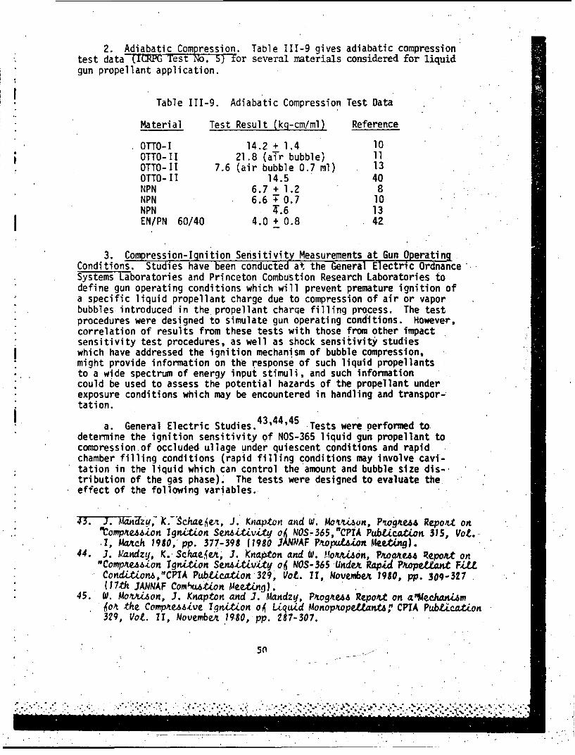
2. Adiabatic Compression. Table 111-9 gives adiabatic compressiontest data (ICRPG st No. 5) for several materials considered for liquid.gun propellant application.
Table 111-9. Adiabatic Compression Test Data
Material Test Result (kg-cm/ml) Reference
OTTO-I 14.2 + 1.4 10OTTO-II 21.8 (air bubble) 11OTTO-II 7.6 (air bubble 0.7 ml) 13OTTO-HI 14.5 40NPN 6.7 + 1.2 8NPN 6.6 T 0.7 10NPN T.6 13EN/PN 60/40 4.0 + 0.8 42
3. Compression-Ignition Sensitivity Measurements at Gun OperatingConditions. Studies have been conducted at the General Electric OrdnanceSystems Laboratories and Princeton Combustion Research Laboratories todefine gun operating conditions which will prevent premature ignition ofa specific liquid propellant charge due to compression of air or vaporbubbles introduced in the propellant charqe filling process. The testprocedures were designed to simulate gun operating conditions. However,correlation of results from these tests with those from other impactsensitivity test procedures, as well as shock sensitivity studieswhich have addressed the ignition mechanism of bubble compression,might provide information on the response of such liquid propellantsto a wide spectrum of energy input stimuli, and such informationcould be used to assess the potential hazards of the propellant underexposure conditions which may be encountered in handling and transpor-tation.
a. General Electric Studies. 4 3 ,4 4 4 5 .Tests were performed to.determine the ignition sensitivity of NOS-365 liquid gun propellant to
comoression.of occluded ullage under quiescent conditions and rapidchamber filling conditions (rapid filling conditions may involve cavi-tation in the liquid which can control the amount and bubble size dis-,
tribution of the gas phase). The tests were designed to evaluate theeffect of the following variables.
43. J. 7? oanzy,- ".-'Schae•vL, J. Knapton and W. Mov,4ý,un, Ptog'tuA Report. on"Comp4e,64,on Ignition SenMtZivity o6 NOS,-365,"CPTA Pubtication 315, Vo.L.1, Ma1ch 1980,' pp. 377-398 (1980 3ANNAF P.•pul•ion Meeting).
44. J. Vandzy, K. Schae.jzeA, .-. knap~ton and W. Mo~xA.dn, PAouaa Repo.t on"Comp4az..6~on IgnLtion Sen6LtLvity o6 NOS-365 Unde. Rapid P,.IopJttaJt FiUtCondition6,"CFIA Pubicat.on 329, Vot. 11, NovembeA 1980, pp. 309-327(17th .IANNAF Comixati.on Mee.ting.
45. W. Movu on, -J. Knapton and .J. Mandzy, Ptog4A4 Repoat on a"Mechani~m4oA. the CompxesAive Ignition o4 Liquid Monop.opelanta," CPIA Pub!izat.on329, Vot. 11, NovembeA 1980, pp. 287-307.
5(0
. . .
- ......
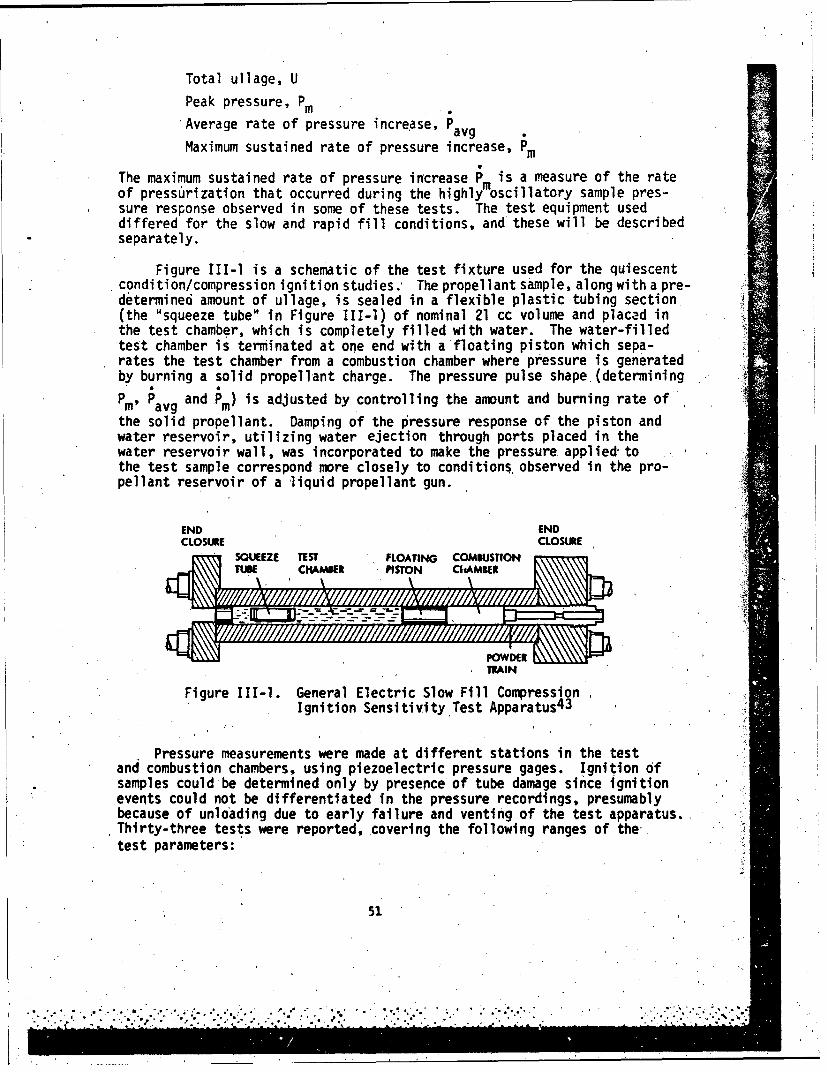
Total ullage, U
Peak pressure, Pm
Average rate of pressure increase, Pavg
Maximum sustained rate of pressure increase, Pm
The maximum sustained rate of pressure increase Pm is a measure of the rateof pressurization that occurred during the highly oscillatory sample pres-sure response observed in some of these tests. The test equipment useddiffered for the slow and rapid fill conditions, and these will be describedseparately.
Figure III-1 is a schematic of the test fixture used for the quiescentcondition/compression ignition studies. The propellant sample, along with a pre-determined amount of ullage, is sealed in a flexible plastic tubing section.(the "squeeze tube" in Figure Ill-i) of nominal 21 cc volume and placed inthe test chamber, which is completely filled with water. The water-filledtest chamber is terminated at one end with a'floating piston which sepa-rates the test chamber from a combustion chamber where pressure is generatedby burning a solid propellant charge. The pressure pulse shape (determining
m Pavg and Pm) is adjusted by controlling the amount and burning rate ofPm'
the solid propellant. Damping of the pressure response of the piston andwater reservoir, utilizing water ejection through ports placed in thewater reservoir wall, was incorporated to make the pressure applied tothe test sample correspond more closely to conditions, observed in the pro-pellant reservoir of a liquid propellant gun.
END ENDCLOSURE CLOSURE
SQUEEZE TES FLOATING COMBUSTION iTUXE CH4AMBER PISTON ClAMBER :
11MAIN
Figure 111-1. General Electric Slow Fill CompressionIgnition SensitivityTest Apparatus 4 3
Pressure measurements were made at different stations in the testand combustion chambers, using piezoelectric pressure gages. Ignition ofsamples could be determined only by presence of tube damage since ignitionevents could not be differentiated in the pressure recordings, presumablybecause of unloading due to early failure and venting of the test apparatus.,Thirty-three tests were reported, covering the following ranges of the-.test parameters:
51
*. " . S.".. . . ." .. . . . . .""
"",,'.. . . .. . . .. .•T".. . . .. .... . . . . .

0 < ullage < 2.0 cm3
Peak pressure < 120 kpsi
Average pressure increase rate < 413 kpsi/msec
Maximum sustained pressure increase rate <3400 kpsi/msec
In the thirty-three tests reported, two definite and four "possible"ignitions were observed. For ullages up to 2.0 cm3 , Do ignitions wereobserved in the test parameter space: Pm.< 55 kpsi, Pavg < 80 kpsi/msec,
Pm < 1000 kpsi/msec. It was noted that the ignition events observed
appeared uniformly distributed with respect to the variable U, but it wasobserved that the ullage (in samples removed intact, i.e. no ignition ortube failure) had been broken into many smaller bubbles with diameters ofthe order 1 mm. It was therefore hypothesized that the bubble sizewhich was determining the sample response may have been similar in alltests and independent of the total ullage. It was suggested that ignition
was correlated with Pm, which'was determined as the rate of pressure"
increase measured in the first cycle of the oscillatory sample pressureresponse, and that the data from these tests could be correlated with the
product of the peak pressure Pm and pressure rise rate Pm"
Figure 111-2 is a schematic of the test fixture used in the GeneralElectric rapid filling/compression ignition studies. The test method issimilar to the tests under quiescent conditions in that compressionis effected by the expansion of gases from a solid propellant chargeand controlled by modification of the amount and/or burning charac-teristics of that charge. A piston terminates the gaseous product(combustion) chamber and is followed by a water volume which, throughthe use of exit ports in the fixture walls, provides damping of pres-sure oscillations to provide pressure histories similar to thoseexpected under gun operating conditions. The water damping volume isterminated by a regenerative piston behind which the propellant-testcharge (22-55 cc) is introduced. The propellant is loaded by a pneu-matically driven system using pressurized nitrogen. The ullage to beentrained into the propellant charge is prepositioned inthe fillline just outside the test fixture. The filling procedure is*designed to mi-nimize cavitation during the filling process and to dis-tribute the ullage in the test chamber (breakup into a'fine bubblefield). Flow visualization experiments indicated a distributed bubblefield with bubble diameter of about 0.25 mm. Nineteen rapid fillingtests were reported, covering a range of (liquid) sample volumes from22 cc to 55 cc and ullage fractions of 0% to 1%. Prepressurizationof the samples was 1 kpsi (determined by the pressurized N2 fillingprocedure). In-nineteen tests two ignitions were observed. It wasstated that the pressure rises resulting from these ignitions were"greatly delayed"and would not be observed in gun firing conditionsbecause of the lim ted time of confinement. Although some pressurerecords from selected tests were presented, no systematic presentationof maximum pressures or pressure rise rates were reported.
52
i.•...g•..o~.. •. ... •............... ... i

REAR END BELL PISTONPOSITION/ VELOCITY
,.•.. ~ ~~PROPELLANT INLETvAvFROMp ~oFILL SYSTEMf, jSENSOR I
PIROKELLANT TEST 'tL .E
REGENERATIVE- PISTON
WATER DAMPING PORTS REAR CLOSURES~~CHAMBER 300Y ,
SEPA-ATOR PISTON
REAR WATER SEALi,•! " 'GNITER VALV1E CONTROL LINE
"" ' j& POWDE WATER 5UFFEPR/OAMPING VOLUME
iCOMBUSTION CHAMBER
• F.ONT ENO SELL
Figure 111-2. General Electric Rapid Fill Compression-Ignition Sensitivity Apparatus 44
b. Princeton Combustion Research Studies. 46 ' 47 ' 4 8 Tests were per-formed to determine the ignition sensitivity of NOS-365, LGP-1845 andLGP-1846 liquid gun propellants to rapid compression with different ratesof pressure increase and amounts of finely distributed ullage, with andwithout prepressurization of the propellant charge. Test conditions weredesigned to encompass those conditions which the propellant would beexposed to in gun operating conditions and to evaluate the effect of thefollowing variables.
"Total ullageMaximum rate of pressure increase
* Prepressurization of the liquid charge(before the onset of the rapid pressure increase)
Figure II,-3 is a schematic of the test apparatus used. The propel-lant is loaded into the pneumatic load cylinder from the LP reservoir.The required 'amount of ullage is then'added to the pneumatic load cylinder
46. CPTA P{UW,.4Zn .34-7, 7otmwie 1l1, p. 2671-287 (1981 ,TANNAF.* Combut on Meetni).
47. N. Me.ALna, P~Zinctton Combut.~Zon ReAeaAcd Labo,'uoAie Ze.-tteL.report to U.S. AAmy BaLL,&,tc Ree.a,,•h Labotato4, on Coonte.t No.VAAKt I-82-C-O011, RepoAtin.g Pet.iod Januwvu 1, 1982 to Mtckh 31,1982.
48,. N. Me44ian,, P'ince.tont Combu,6tion ReuAeAch Labbo'wzto•e• Zettex %e.pot•t.to U.S. AAmq Battiatic Raea~hk Labo'ttoty on Cont,•e.t No.
"AAKII-82-C-OO11, Repo&ttrng Pepiod Ap'i2 1, 1982-Moaq 31, 1982.
530i;

RESERVOe• TiM LAAM ER BLtEED LEAD TOL VALV
SOELS POOF SEAO PISHTON LASTOC•OATION OF IGHT SNORS
Figure 1-3.STARTER CHARGE C ombustion LbRAtorCEieS
omPRESSU SnivtyApru
SPtSTON LAS , SH I NELD-\
cylider IINCOThe L prpelatC fostruh h optvav wihi
Sadomstabllag springlaed, Raint the in copeson chamber.pelath sapleingm
W setting on the poppet valve determines the prepressurization of the pro-• pellant charge in the compression chamber. When the propellant charge@1 drives the projectile piston to the end of the compression chamber (t~he•i';ichamber is filled) ,the piston actuates a time delay circuit which fires•o . an electrical primer..actuating the smokeless powder ch~arge in the starter•--. charge chamber. Variable time delays, up to 10 msec, were used to--. ;.allow for bubble aggregation following the rapid filling process. PressureS~buildup due to the expanding combustion gases from the burning smokeless
__. __ powder drives the separator piston to the right, compressing the propellant... '°-" charge .'
":.'- The volume of the sample test chamber is 6.65 cm3 ,. The pressure pulse".: ~shape is determined by varying the type of smokeless powder charge.. Maxi-.•'" mum liquid pressurization rates '(dP.Idt) of 25,.40, and 70 kpsi/msec• ~were obtained with different types of fuse section and. ma'n (combustion)
,.-.. chamber powder charges..
S .. Figure III-4 indicates the results of eleven tests of NOS-365 pro-:.- pellant at different values of the test parameters.
0A
i54
. ... . .
!' -... ...'..-'.."....;,.; . "' .".,....... •'.' "i.';•, /.".'................S;'"" ""'1"
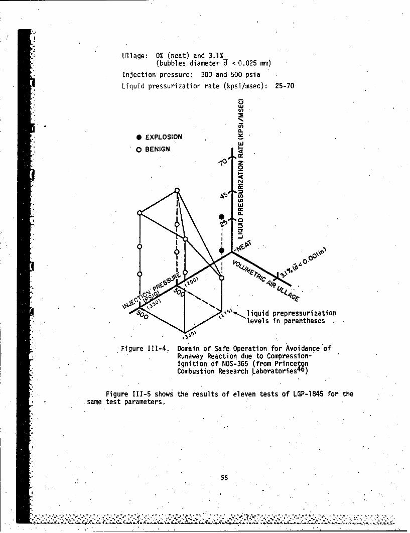
Ull~ge: 0% (neat) and 3.1%(bubbles diameter U < 0.025 mm)
InJection pressure: 300 and 500 psia
Liquid pressurization rate (kpsi/msec): 25-70
* EXPLOSION
o BENIGN !a
0
404
NM)UL
CY
J"N% iquid prepressuri zationlevels in parentheses
Figure 111-4. Domain of Safe Operation for Avoidance of* . Runaway Reaction due to Compression-
Ignition of NOS-365 (from PrincetonCombustion Research L~aboratories'16)
Figur~e 111-5 shows the results of eleven tests of LGP-1845 for the* .same test parameters.
55
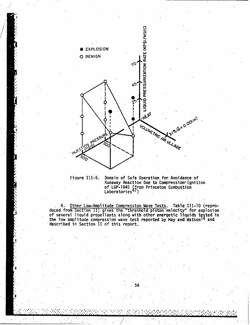
/M
U,
0.
* EXPLOSIONW
"0 BENIGN•" ,10 %M
- z
0N
0.
g"L
Fiqure 111-5. Domain of Safe Operation for Avoidance ofRunaway Reaction Due to Compression-Ignitionof LGP-1845 {;rom Princeton CombustionLaboratories)
4. Other Low-Amplitude Compression Wave Tests. Table 1ll-10 (repro-duced from Section II) gives ,the "threshold piston velocity" for explosionof several liquid propellants along with other energetic liquids tested in"the low ampli.tude compression wave test reported by Hay and Watson 14 and
'described in Section II of this report.
4
I
"56
*..7~~~~~~~.. - . . .. . . . . . . . . ..... ... . . .. .--'-7 ."' """"".- ; """ • -• "."""
I .4
Table III-10. Low Amplitude Compression Wave Test. Data 14
"ThresholdMaterial Test Temperature (°F) Velocity (m/sec)
' NOS-365 104 and 108 26.2 + 2.7NPN 68 91.3 T 1.3OTTO-II 68 23.4 + 3.2NM 68 24.1 V 2.3NM/Benzene 70/30 68 >IT4"NM/i/NP 52/48 68 90.2 + 0.6NM/2/NP 53/47 68, >IT7NM/Toluene 70/30 68 >122H 68 > 76
- MMAN 88% 165 24.3 + 5.6MMAN 69% 165 58.9 + 5.8EGMN 75% 68 53.7 + 7.3EGMN 50% 68 .' 55.3 + 8.0EGMN 38% 68 >1-3
* C. 'Shock Sensitivity Tests
1. Card Gap. Table III-1l summarizes several card gap test resultsfor liquid gun propellants, and some other energetic liquid materials.forcomparison, reviewed in this work. In all cases reported in Table III-11there was at least'a strong suggestion that the test was the standardNOL test described in Section II, but detail's Were not given. It cannotbe ascertained without a followup contact with the report originatorswhether the data are all on a comparable test (i.e. same container,
- . etc.) basis. It is noted, for example, that two widely different valuesfor OTTO-II are reported. Where' temperature was not specified, it isassumed to have been room temperature or. 250C.
Table 111-12 gives "modified card gap test" results for NOS-365,OTTO-II,and hydrogen-hydrogen nitrate-water mixtures reported by Pulse-'
* power Systems, Inc. 49 The test method was reported to be the NOL testwith modifications as follows:
. 49. PuZaepowe4 Syatem6, Inc. ,"Stdy "6 Ignition and Combut.on o6 LiquidPuope•,nta 6o4 Gun6 "MonmthWq Pf.oguu Repokt, TR-140 (Oct. 1977),TR-141 (Nov. 1977), tR-142 (gee. 1977), and TR-143 (Jazn. 1978) toU. S. AMmy BaZtti,, c ReeaAeh Labo~utoty, Conrtmet'N00123-73-C-19S2,Mod PO0013.
* 57
.. ........ ..... ..-..-...-............... -..

.qTable III-11. Card Gap Test Data for Potential
Liquid -Gun Propellants
Material Card Gap Remarks Reference
OXSOL-I 0 (3 tests) NOL test 37OXSOL-2 0 (3 tests) NOL test 37NOS-5 0 40NOS-283 0 (3 tests) NOL test 38NOS-365 0 (3 tests) NOL test 38OTTO-II 120-150 MILS NOL test 38"OTTO-II 10 MILS 40NM 190 MILS NOL test, 42
Obc
NM 470 MILS NOL test, 42800C
H Insensitive NOL test, 42"EN:PN 60/40 100 MILS NOL test 42EO 0 MILS NOL test. 42EN 200 MILS NOL test 42NM 230 MILS NOL test 42*NEN 480-500 MILS .NOL test 42*attributed to Naval Ordnance Laboratory
" a. Acceptor containers were 1-7/8 inch OD x 1-7/16 inch ID seamlessmechanical (steel) tubing of varying' lengths (6-7/8 to 20-7/8 inches).
b. Two 2-inch OD x 1-inch thick pentolite pellets initiated witha No. 8 cap were used as the donor.
"c. DuPont T-2 gages were incorporated in the tube wall for measure-ment of station-to-station average shock velocity.
d. In some tests witness rings' were incorporated around the tubeto aid in assessing energy release.
e. Provision was made for addition of air bubbles and testing atelevated fluid temperatures.
* The last three entries in. Table 111-12 are for inert liquids to test theeffect 'of shock coupling from the'pentolite. donor to the liquid in the
test container. 'The water-zinc chloride-ethylene glycol simulated thedensity and viscosity of NOS-365.
0
58
* . . * *.*- w .• . - . e • • l • . ,.% * '- - - -, e .*--' - - '. -.. .,. .- oo q . - • . . o . .

Table 111-12. Pulsepower Systems, Inc. Card Gap TestSummary 4 9
(all tests at zero card gap)
Velocity**, km/secTube Temperature (Station 1 to Station 2)/
Material Length (in.) ( 0C) Bubbles* (Station 2 to Station 3)
NOS-365 14 Ambient No' 2.3NOS-365 20-5/8 Ambient No 2.1/1.9
NOS-365 20-5/8 Ambient No 2.2/1.9
NOS-365 20-5/8 Ambient Yes 2.1/1.6
NOS-365 20-5/8 Ambient Yes 2.1/1.6NOS-365 20-5/8 60 Yes 2.1/1.6
NOS-365 20-5/8 60 Yes 2.1/1.6
NOS-365** 20-5/8 60 Yes 2.3/1.8
NOS-365*** 20-5/8 60 Yes 2.0/1.6
OTTO-II 13-3/4 Ambient No 3.8
OTTO-II 20-5/8 Ambient No --
oTTO-II 20-5/8 Ambient Yes 2.9/1.3
OTTO-II 20-5/8 60 Yes 5.7
H-HN-H 20 6-7/8 Ambient No 5.7(63/32/5)
. H-HN-H 20 20-5/8 Ambient No 9.5/8.2/8.2/6.7"***(63/32/5)
H2 0 20-5/8. Ambient No 1.8/1.5
Glycerin 20-5/8 Ambient No 2.9/1.5* H20-ZnCl-EG 20-5/8 Ambient No 1.9/1.5
*Bubble size reported 1 mm diameter.
"**Station distance from tube bottom: #1, 1-5/8"; #2, 6-1/3"; #3, 10-5/8";
"#4, 15-1/8"; #5, 19-5/8".***Denotes different sample lot.
****Five velocity stations.
r.
59
. . .* ,.-... . -. , ... , .. , . .. . .. '... '." . . ....""" -%

Table 111-13 gives measurements of "detonation velocity" reported byCruice 3 6 for several liquid gun propellant fuels, oxidizers,and mixtures.The test procedure is dnother modification of the card gap test. Theprimary test result is the propagation velocity of the shock wave throughthe sample material which is induced by an explosive donor. The materialis contained in a section of schedule 80 stainless steel tubing (2 inch,ID) 8 inches long. The tube bottom is sealed with a thin plastic dia-phragm. The 160 grams RDX donor is placed' directly below the diaphragm."A cold-rolled steel plate 4" x 4" x 3/8" thick placed on top of the sample"container serves as a witness plate. The container is equipped with a con-stant current resistance wire circuit for measurement of the reaction wavevelocity.
Table 111-13. Detonation Velocity Test Results 36
DetonationMaterial Velocity (km/sec) Remarks
2.8 Molar HAN 1.83 Tube in strips, plate OK, nodetonation
2.8 Molar HAN 1.87 Tube in strips, plate OK, nodetonation
11 Molar HAN 2.21 Tube in strips, plate OK, nodetonation
11 Molar HAN 2.15 Tube in strips, plate OK, nodetonation
13 Molar HAN. 2.70 Tube in strips, plate OK, nodetonation
13 Molar HAN -- Tube in strips, plate OK, nodetonation
NOS-365 2.63 Moderate tube.fragmentation,plate bowed, LVD*
NOS-365 •3.05 Moderate tube fragmentation,plate bowed, LVD*
LGP-1776 2.35 Moderate tube fragmentation,plate broken, LVD
LGP-1776 2.49 Moderate tube fragmentation,plate bowed, LVD
LGP-1845 2.56 High tube fragmentation, platebroken, LVD
LGP-1845 2.35 High tube fragmentation, platebroken, LVO
*Low velocity detonation
- 2. Impedance Mirror. Table'.,Ill-14 gives reaction times (time for"*i passage of the reaction zone) reported by Mallory50 using the impedance
mirror test described in Section II.
50. H. MaUoto",' Fu o.ton and Saiety Te.t6 o6 NOS-365 MonoptopeU-. ,Nava2 Weapon.6 Cente, MUCT. 5940, China Lake, CA, ApA.L. 1977.
6
S60
rw,,.,.. o, ..... ,-.....". * .,,. . .... .*, , *," .. . ... .. , .; .. .,..... .. ....-, . ,
. . . . . . ,.,.... . . . .

Table 111-14. Reaction Times Measuredwith the Impedance MirrorTest
Material Reaction Time (psec)
NOS-365 - 10.0
NM 0.22 + 0.03
NM/Acetone .75/25 0.4
3. Heavy Confinement Shock Tests. Shock sensitivity tests ofliquid gun propellants agg torpedo' fuels confiqd by heavy wall tubes havebeen reported by Mallory and by Mason etal.'
a. Mallory reported tests of NOS-365 and nitromethane in heavy walltubes as follows. A mild steel tube, 25 mm ID, 25 mm wall thicknessand o.g m length was closed at one end with a welded steel plug. AnRP-81 exploding bridgewire detonator was lowered to the bottom .(closedend) and the tube was filled with the test liquid. The tube top was open.Figure 111-6 shows the fragmented steel tube which contained 'NOS-365 at15-21*C, and Figure 111-7 shows the fragmented steel tube which contained13-molar HAN solution at approximately 15*C. Mallory stated the fragmentsof the tube. in both tests indicated brittle fracture patterns frequentlyobserved in ruptured pressure vessels failing at low pressures; no measure-ments were made to determine whether detonation velocities were achieved.A 0.76 m length of 4340 steel Mann barrel, 20 mm ID and 19 mm wall thick-ness, wa3 closed at one end with a welded steel plug. The barrel whichcontained a 2.5 gram tetryl pellet attached to an RP-81 detonator wasfilled with the test liquid. :7igure III-8a and III-8b show the Mann barrelwhich contained NOS-365, indicating failure at a distance of about 12-15 in..from the booster; and Figure III-9a and III-gb show barrel fragments from
"- tests with nitromethane' and composition C-4 respectively.
b. Mason, Ribovich,and Weiss12 reported tests of OTTO-II torpedofuel with the confinement test described in Section II. The test resultis shown in Figure III-10 which indicates complete fragmentation of thetube and holing of the witness plate.
4 D. Miscellaneous Tests
"1. Cap Sensitivity. Smith and Harrison3 reported d negativeresponse to J-2 Cap Sensitivity Tests for OXSOL-I (3 trials) and OXSOL-II,"(5.trials). Kirshner and Silverstein4 2 reported negative response toNo. 8 Cap Sensitivity Tests for OTTO-II fuel.
2. Trauzl Block. Kirshner and Silversteln4 2 reported that hydrazine-hydrazine nitrate water mixtures with more than 6% water gave only "partial"or low order detonation response in the trauzl block test.
61
•'-....-......-...-....i. .... " ... • . .-." ".'..'--.'- .. ' . ....-.-"-'"- -' . ...-..".L"- ' . '. ""* •.-•"

Figure 111-6. Tube Test Fragments of Mild Steel fromDetonation of NOS-365 50
1 2 3 4 s inches
L.,
S•-"Figure III-7. Tube Test Fragments of Mild Steel from"Detonating 12 Molar HAN Solution50
I..
662 6J
t ..
4,1
Ib
Closeup of detonatiOn section
Figure 111-8. Section of 20 rm' Mand Barrel Used inJ
NO S -36 5 Te s t 5
1
63

%rt
a.
Ni tromethane
Composition C-4.
Figure 11 1-91. 20 mmi Mann Barrel Fragnnts from .Tests onNM and Composition C-4
64
;r
WHIM!
Figure llI-10. Confinement Test Results for OTTO-I
Table 111-15 gives Trauzl Block Test results for several liquid gunpropellant fuels, oxidizers and mixtures.
Table 111-15.' Trauzl Block Test Results 36
V cc/gram'Material 1 gm Load 2 gm Load 3 gm Load
2.8 M HAN 1.0 1.0 1.011 M HAN 4.4 3.0 3.713 M HAN 5.0 " 4.0 .4.5IPAN 0.5 1.0 0.7TMAN 0.6 1.2 0.9TEAN 3.0 1.5 2.7NOS-365 4.0 3.2 3.6LGP-1776 6.5 3.0 4.7LGP-1845 6.0 4.2 5.1
3. Bullet Impact. Table 111-16 gives'reported bullet impact testresults for several liquid gun propellants and some other energetic liquidswhich are included for comparison. These data are included in the"miscellaneous" test category rather than in the section on impact
65
• -° . • " " i";' "" " ".' .. ", **. '- .. ." ' .. " " : .' " . . .- .. . " .'': . -,-; ." ' '"

sensitivity due to the relatively poor test condition definition and thefact that the test is directed to the containment of the liquid.
Table Ill-16. Bullet Impact Test Data
Material Test Condition Result Reference
NOS-58 No details given Positive (explosion) 40NOS-283 u.50 caliber No detonation, nO fire/ 38
5 testsNOS-283 0.30 caliber No detonation, no fire/ 38
20 testsNOS-365 0.50 caliber No detonation, no fire/ 38
2 testsOTTO-II No details given Negative (burned) 40OXSOL-I No details given Negative/4 tests 37OXSOL-II No details given Negative/4 tests 37NPN A-25-I* 3 explosions/3 tests 51NPN A-25-HE 3 explosions/3 tests 51NPN A-95-I 3 explosions/3 tests 51NPN A-95-HE 3 explosions/3 tests 51NPN. A-95-.30 cal No explosion (burned 51
quickly)H A-25-I No explosion/3 tests 51H A-25-HE l'small explosion/3 tests 51H A-95-I No explosion/3 tests 51H A-95-HE Explosion/3 tests 51H A-95-.30 cal No explosion or flames 51HN Sol'n A-25-I No explosion/2 tests 51HN Sol'n A-25-HE 2 explosions/3 tests 51HN Sol'n A-95-I No explosion/3 tests 51HN Sol'n A-95-HE 2 explosions/3 tests 51EO A-25-I, HE Ignited, orange fireball 51EQ A-95-1', HE (every test/ 12 tests) 51Aviation Gasoline
.(115/145) A-25-I Fire (2 out of 3 tests) 51'(115/145) A-25-HE No flames or explosion 51(115/145) A-95-I Fire (2 out of 3 tests) 51(115/145). A-95-HE Fire (I out of 3 tests) 51
*A-B-Cwhere A = aluminum container, 6061, wall thickness = 0.064 in.
B = % liquid filledC = ammunition (I = 20 mm incendiary, HE = 20 mm high explosive)
51. G. G ,atta"Stabz&cy TeAt.6 o6 MonopptopoeZZtant ExpoAed -to FRamaeA and•it. FiAe,"Je.t Popu.aion Laborato'y Techni'cat Repott No. 32-112,CaZio'tnZa ln6titu~te o6 TechnoZogy, Pahadena, CA, Feb'wAuy 26, 1962.
66.
....... ......-....-.. . .- .

"' 4. Bonfire and Unconfined Burning. Glatts 51 reported qualitative"observations of response of hydrazine, hydrazine nitrate solution, normalpropyl nitrate, ethylene oxide, and aviation gasoline (for comparison)in one gallon aluminum cans to wood and oil fire exposure. Explosions ofvarying intensity (and time to explosion) were observed for all thesematerials. Romero3 9 reported that NOS-365 in a one gallon plastic con-tainer in a full metal shipping container with fiberglass packing did notexplode in a wood bonfire but did ignite and burn quickly (30 seconds).Smith and Harrison3 7 cited negative results (presumably meaning no explo-sion, but no details were give8 for OXSOL-I and OXSOL-II in an "unconfined"burning tests. Cziesla et al. .u reported that OTTO-II did not detonate inan unconfined burning test but that NOS-283 did detonate in the sametest.
67
* .. . , . . -.,. , . - . . %
I. . . . . .
. . . ..-...
* V

IV. DISCUSSION AND RECOMMENDATIONS
"The purpose of this study was to review the hazardous material safetytesting methods which have been applied to energetic liquids and to providerecommendations for their 'use, along with additional tests which might be"indicated, for the assessment of liquid gun propellant reactivity (explosivity)hazards.
In Section II a rationale for development of a protocol for safety test-ing of liquid propellants is suggested. Test procedures are required whichwill quantify the response of the propellant to energy input conditions whichmay be experienced in handling, storage,and transportation. It is desired that
-' the propellant should not react violently to such energy input conditions.Since the propellant must react with rapid, but controllable, energy releasewhen ignited in the gun barrel, it is required that the differences in con-ditions experienced by the p:.opellant in the gun application and in storage,handling,and transportation be quantified. Such conditions include thermal
*:. energy (heat) inputs and energy inputs to. the material by localized compres-sion, such as might be experienced due to impact in a transportation accidentor in the pre-ignition pressurization of propellant during gun loading.Thermal explosion theory suggests the response of a propellant to energy inputs
*e depends not only on the rate and magnitude of the energy input but also onother initial and boundary conditions imposed on the material. It followsthat the response of the propellant to energy inputs can depend on the
- material's confinement and on its initial state (such as temperature orpresence of air or vapor bubbles).
Current safety testing procedures for energetic liquids, described inSection II, rely on comparison of the responses of different materials to aparticular energy input condition. Most of the tests described weredesigned to provide a purely relative measure of the sensitivity of ener-getic liquids to the selected test condition rather than to provide infor-mation which could be used to predict the responses of a specific materialto more general conditions. Further, the test conditions appear to havebeen selected with primary orientation to the identification of hazardousresponses which might be experienced in the propellant end-use application.For example, a measure of the propellant's propensity for detonation (andits prevention via propellant application equipment design) appears tohave been a primary focus for the test procedures.
The application of the-described test nethoas-to-assessment of poten-tial hazards associated with liquid gun propellants in storage, handling,and transportation is difficult for two primary reasons: First, the con-ditions'which characterize the normal and accident transportation, storage,and handling "environment,"i.e. the characteristics of the energy inputs,
* that can be expected, are not known. This problem, although long recog-nized, has received little attention, even though such information isprerequisite to the specification of'test conditions to be applied in safetytest protocols. Second, the individual test procedures, each addressing"only one specific energy input condition, can provide only one input to anenergy input-material response matrix which would encompass the conditions
* anticipated in storage, handling,and transportation. Unless the individual
68
6~

test results are considered with results from other tests which provide addi-tional information about the material's response to conditions that in some"meaningful way imitates those which may be experienced in handling,.storage,and transportation; their application to determining the safety of amaterial can be difficult, if not misleading. Furthermore some of the testsinvolve fairly subjective "go/no-go" results, i.e. the standard card gap anddrop weight tests which involveobservation of mechanical damage of a par-ticular degree (witness plate holing or sample'container failure). Thesefactors make it difficult to compare sensitivity "between tests" and, in somecases, to provide quantitative ordering of sensitivity of differentmaterials to, the same test.
From this survey it appears that the characterization of the sensitivityof a material to explosive energy release during storage, handling,and trans-portation, inevitably requires a number of tests which provide information"about the material's response to difterent energy input conditions. In this
* regard the study reported by Cruice,-3 which describes the application of abattery of tests to determine the sensitivity of liquids for hazard classi-
* fication for shipping provides information for safety assessment whichcannot be obtained from any single test procedure. However it appears that.the test battery performed by Cruice was specified primarily to provide areasonably close correlation with the test protocol used for military solidexplosives as described in Department of the Army Technical Bulletin Cl,TB 700-2; and it is not clear how well -such a test protocol relates to theconditions to be encountered in storage, handling,and transportation. Theclassification proposed by Cruice addresses two types of energy inputs:thermal and impact/shock. It is probable that the use of a battery of tests
"* such as proposed by Cruice for determining sensitivity to thermal energyinputs, which includes (a) Flash Point and Ignition Temperature determina-
Stion. and (b) thermal stability determination including isothermal, longterm exposure and programmed temperature studies, with provision for obser-vation of confinement and container catalysis effects, provides sufficientinformation on sensitivity to thermal stimuli to allow confident orderingof the thermal energy input sensitivity of liquid propellants for safetyevaluation purposes. However, it is less clear how well the test proceduresfor impact/shock energy input provide information for assessment of potentialhazards in storage,handling,and transportation. Such judgments can onlycome from comparison of test results for gun propellants with those obtainedfor other materials for which there is a history of satisfactory performancein the storage, handling,and transportation environment. Consequently,the results of a battery of tests on liquid gun propellants would be moreuseful for hazard evaluation if the test battery were also applied to-otherenergetic liquids such as nitromethane and nitroglyter~ine for comparison.It also appears that'certain kinds of conditions which might lead-to lowVelocity detonation of 'some of the propellants might not be sufficiently'delineated in a test protocol such as the one suggested by Cruice.
Aside from the problem of.definition of the conditions to be tested* for, i.e. the range of conditions which the propellant will be' exposed to
in the transportation, handling,and storage environment, the data availableon the .response of liquid gun propellants to the tests described in SectionII is fragmentary and not sufficient for the evaluation of the test's use-
*T fulness for delineation of liquid gun pronellant hazards. However, it is
69
4..
*.,* ,
-"-" ' •". . -.- -.. .-. ' __ -,--...- ... . -')•, ' 4 v " "" ''" " " ••
9
instructive to attempt a sensitivity ranking of liquid gun propellant*: materials using the data available from the "standard" impact and shock
energy input tests,
Table IV.l gives results of card gap, drop weight, adiabatic compression,and low amplitude compression wave tests, summarized from Section III, forseveral liquid propellants. Table IV.2,gives a ranking for the materialsfor each test based on the data of Table IV.l. Lower numbers denote higher"1 sensitivity" as measured by the test result. The materials shown areranked similarly by the drop weight, card gap, and adiabatic sensitivitytests. However', a different ranking is obtained based on the results of thelow-amplitude compression wave test. The similar indications of "sensitivity""for OTTO-II, NOS-365,and NM obtained from the low amplitude compressionwave test, which is in contrast to the indicated order of sensitivity forthese materials based on the drop weight, card gap, and adiabatic compres-sion tests, as well as from measurements of reaction rates (times) such asthose presented by Mallory, 5 0 are important to understand for purposes ofsafety evaluation. This difference in ordering is not surprising, in viewof the wide differences in the energy input magnitude and rates and in theboundary conditions imposed on the material in the different tests. It maybe that the low amplitude compression wave test result is indicative of asimilar propensity for low velocity detonation of these materials underthat specific test condition and the other three tests may not (probably do
* not) measure this propensity. At has'been noted by Watson, the lowamplitude compression wave test indicates a similar propensity for explosiveenergy release (probably best-characterized as LVD) that would not be indi-cated for NOS-365, OTTO-II,and NM from the other three tests. It has beensuggested that the conditions experienced in the low amplitude compressionwave test may better imitate the conditions experienced in some trans-portation accidents.
Table IV-l. Selected Test Results forLiquid Gun Propellants
Material Drop Weight Results for Low Amplitude NOL Card Gap(kg-cm) Adiabatic Compression (mils)
Compression Threshold_-_ _(kq-cm/ml) Velocity (ni/sec)
NOS-365 152 -- 26.2 0OTTO-II 8.5-34.2 '7.6-21.8 23.4 10-150H >200 -- >76 0PN 15.5 4.6-6.7 91.3 --EN/PN 5.8 4.0 -- 100NM 37.3 10.4 24.1 150-300NG 2.5 .... 380-500
07
%70
L . ..- .......... "" - -

Table IV-2. Sensitivity Order of Test Resultsfrom Table IV-l
" Test NOS-365 OTTO-II H PN EN/PN NM NG
Drop Weight 6 4 7 3 2 5 1"Adiabatic Compression -- 4 -- 2 1 3 --Low Amplitude
Compression Wave 1 1 2 3 -- 1 --NOL Card Gap 5 4 5 -- 3 2
Additional work is required to provide a better data base for predictingand assessing the hazard potential of liquid gun. propellants, and the follow-ing recommendations are offered.
1. A basic program should be undertaken to provide test results for theliquid gun propellants of current interest, as well as a number of otherenergetic liquids (such as nitromethane, ethylene oxide, nitroglycerine,for which there is an extensive "experience" data base) using the instru-mented Card Gap Test, the drop weight and adiabatic sensitivity tests, thethermalsurge test,and the low amplitude compression wave test. Thisrequirement is necessitated by the current lack of data on these materials
4 which can be meaningfully compared. The proposed exercise is similar to thatperformed by Cruice° but would include additional test procedures and other
.. energetic liquids for comparison.
2. A parallel effort should be made to characterize the input energyand boundary conditions for each of these tests to provide a means forevaluating the tests with respect to "severity" and correspondence to con-ditions which may be encountered in handling, storage, and transportation.Some work along these lines, directed to characterization of the drop weight,adiabatic sensitivity,and card gap tests, has been done by the Bureau ofMines. It is expected that such an effort would indicate that some testsnow performed are redundant or not applicable to liquid gun propellantsafety evaluation'.
3. A series of tests utilizing the card gap principle should be run, to determine the effect of confinement on the propensity for low velocity* and high velocity detonation. These tests should be instrumented to obtain
continuous reaction front velocity and pressure as a function of distance.Presence of gas phase (bubbles), degree of confinement, and reactiontime (length of reaction path)' should be. test variables. This test seriesshould provide information onthe propensity for low velocigy detonation.These tests would be similar to those conducted by Cruice,, Pulsepower Systems,"Inc.,49 ahd the Bureau of Mines 3a but would provide for additional 'testvariables and would be carried out for a number of other.energetic liquids,for which there is 'good "experience" data.
4. The compression sensitivity tests as conducted by Princeton Com-bustion Research Laboratories46,47, 8 should be conducted'for the other
*Z liquid gun propellants of interest and for other selected energetic liquidsfor comparison. Although these tests were designed to provide information
7
b'71
-,
'A * * '
•" " "" " " •-o" " ~~... .. L.""•....."....' ...". ""-'""

on safe gun operating conditions, they should also be useful in determining- the relative sensitivity of gun propellants compared to other energetic-' liquids for which there is a better experience data base.
5. Methods should be explored for acquiring more fundamental data,*, on the energetics and kinetics of reaction of liquid propellants. Measure-
ment of global rate and activation energy constants, using techniques such"as accelerating rate calorimetry should be evaluated. Data from constant
* volume proýýljnt burning tests conducted at the Ballistic ResearchLaboratory ' (which were not reviewed in this work) should be evaluatedfor their application to the identification of sharp pressure transitions
. due to changes in the mode of combustion, as .•bserved for NOS-365 propellant.The latter may be important in the determination of design criteria forsafe containers.
6. Finally, it must be emphasized that the development of test proto-cols must take into account the anticipated practices regarding, con-tainer types (which will determine confinement and chemical compatibilityeffects) and sizes (which may determine inertial impact effects as well as(self) confinement).
*57. 77 H. CorneAp , 'gniton and CombdAetion o6 Uqu.Ld UonoptwpeJ~a~n~tA Ut* ~~High Pu~ueA6We," SixtSeen~th It~ue'nationat Sympo6~.Zw on Combuldati.on,
'MIT, Camb4idqe, MA, 15-21 Aug. 1976, pp. 1211-1217.53. W. F. Mc&~a.tney,"Windowed ChambeA inveutigation oj ~the Su.~n~infl Ra.te
o4L Liquid Monop'wpe.Uan~t6 6o4T Gwt6, "'U.S. Amnq PatLLatc Re.AeatchLabo~.oto4yj 4ernoI~andw,, Repo~t ARBRL-PfR-03OT, 1980, AV- A086106.
72
S
................................................................................ °

REFERENCES
1. N. N. Semenov, C hemical Kinetics and Chain Reactions, Oxford Univer-sity Press, London (1935).
2. D. A. Frank-Kamenetskii, 'Difftivin and Heat Fxchanae in ChemicalKinetics, Princeton University Press, Princeton, NJ (1955).
3. P. A. Kendall and J. M. Rosen,"Thermal Initiation Apparatus for HighEnergy Materials,"Rpyviw of Scientific Tnstriiment5, 39, 7, pp. 992-994, July 1968.
4. J. Wenograd, Transactions Faraday Society, 57, p. 1612 (1961).
- . 5. D. R. Stull,"Fundamentals-of Fire and Explosioit,"AIChE MonoaraDh] Series 1O 73 (1977).
6. Test No.' 4,*"Drop Weight Test," Liquid Propellant Test Methods, LiquidPropellant Information Agency, The Johns Hopkins University, SilverSpring, MD (now CPIA, Laurel, MD), December 1959.
7. Test No.-5, "Adiabatic Compression Sensitivity Test," Liquid Pro-pellant Test Methods, Liquid Propellant Information Agency,. The JohnsHopkins University, Silver Spring, MD (now CPIA, Laurel, MD), Decem-ber 1959.
8. G.' A. Mead,"Compressi6n Sensitivity of Monopropellants,'ARS Journal,29, 2, pp. 192-198, 1959.
9. C. M. Mason, J. Ribovich, J. C. Couper and M. D. Weiss,"Safety and
Combustion Characteristics of Homogeneous and Heterogeneous Mono-propellant Systems,'Sureau of Mines Semi-Annual Summary Report No.3768, July 1, 1959 to December 31, 1959.
a 10. C. M. Mason,.J. Ribovich and M. L. Weiss,"Safety and CombustionCharacteristics of Homogeneous and Heterogeneous Monopropellant Systems,"Bureau of Mines Semi-Annual Summary Report No. 3788, Januaryl, 1960to June 30, 1960.
11. C. M. Masoai, J. Ribovich and M. L. Weiss,"Safety and CombustionCharacteristics-of Homogeneous and Heterogeneous Monopropellant
* . Systems:'Bureau of Mines Semi-Annual Summary Report No. 3811, July 1,1960 to December 31, 1960.
12. C. M. Mason, J. Ribovich. and M. L.. Wei'ss,"Safety and CombustionCharacteristics of Homogeneous and Heterogeneous Monopropellant
* .Systems,"Bureau of Mines Semi-Annual Summary Report No. 3830,January 1,'19'1 to June 30, 1961.
73
4
,. _____
13. C. M. Mason and J. Ribovich,"Safety and Combustidn Characteristicsof Homogeneous and Heterogeneous Monopropellant Systems,"Bureau ofMines Semi-Annual Summary Report No. 3897, January 1, 1963 to June30, 1963.
14. J. E. Hay and R. W. Watson,"Initiation of Detonation in InsensitiveLiquid Explosives by Low Amplitude Compression Waves,"Sixth Sym-posium (International) on Detonation, San Diego, CA, August 24-27,1976.
15. Interstate Commerce Commission: Exparte 213. Accident Near Mt.Pulaski, Illinois. 305 I.C.C. pp. 81-87, 1959.
16. National Transportation Safety Board. Railroad Accident Report,Burlington Northern, Inc., Monomethylamine Nitrate Explosion,Wenatchee, Washington, August 6, 1974. Report No. NTSB-RAR-76-1.
17. G. D. Edwards and R. K. Rice,"Liquid Monopropellants: DetonationSensitivity,"NAVORD Report 2884, U.S. Naval Ordnance Laboratory,October 1953.
18. M. A. Cook,,,Thp ýripnrp nf Tndmztrial Fxplosivws,"IRECO Chemicals,Inc.,Salt Lake City, Utah (1974).
19. C. M. Mason and E. G. Aiken,"Methods for Evaluating Explosives andHazardous Materials,"Bureau of Mines Information Circular 8541, U.S.Department of the Interior, Bureau of Mines (1972).,
20. R. W. Watson,"Card Gap and Projectile Impact Sensitivity Measure-ments; A Compilation, 'U.S. Department of the Interior, Bureau of"Mines Information Circular 8605, 1973.
21. H. D. Mallory,"Detonation Reaction Time in Diluted Nitromethane,"- Inirnal of Anplied Physirg, 47, 1, January, 1976.
- 22. H. D. Mallory,"Detonation Reaction Time -in Nitroeethane,"Physicof Fluids, 19, 9, September 1976.
23. J, A. Herickes, J. Ribovich, G. H..Damon and R. W. Van Dolah,"ShockSensitivity Studies of Liquid Systems,"Proceedings of Second Con-ference on Explosives Sensitivity, Washington, DC, September 16-17,1957.
24. C. M. Mason ind J. Ribovich,"Safety and Combustion Characteristicsof Homogeneous and Heterogeneous Monopropellant Systems,"U.S..' Bureauof Mines Semi-Annual Summary Report No. 3876, July 1, 1962 to Decem-ber*31, 1962.
.T4

25. R. W. Van Dolah, J. Ribovich, J. A. Herickes and G. H. Damon,"ShockSensitivity of Nitromethane Systems,"Communicrationn of XXXI Tntpr-national Congress of Industrial Chemistry, Liege, Belgium, September7-20, 1958, pp. 121-126.
26. F. C. Gibson, R. W. Watson, J. E. Hay, C. R. Summers, J. Ribovichand F. H. Scott,'Sensitivity of Propellant Systems,"LJ.S. Bureau ofMines Quarterly Report to Bureau of Naval Weapons for the periodJanuary 1, 1966 to March 31, 1966.
27. R. W. Watson,"The Structure of Low Velocity Detonation Waves,"TwelfthSymposium (International) on Combustion, The Combustion Institute,Pittsburgh, Pennsylvania, 1969, p. 723.
28. M. Cowperwaite and D. R. Erlich,"Investigation of Low Velocity Detona-tion in Liquid Monopropellants and Explosives." Final Report of Con-tract F44620-73-C-0054 to Air Force Office of Scientific Research,Stanford Research Institute, February 1974.
29. M. A. Cook, R. T. Keyes and W. 0. Ursenbach, lournal of ApoliedPhysic, 33, 1962, pp. 3413.
30. F. C. Gibson, R. W. Watson, J. E. Hay, C. R. Summers, J. Ribovich,and F. H. Scott,"Sensitivity of Propellant Systems,"Bureau of MinesQuarterly Report to Bureau of Naval Weapons for the Period October 1,1965 to December 31, 1965.
31. C. M. Mason, J. A. Herickes, J. Ribovich, G. Gelernter and J. C.Couper,"Safety and Combustion Characteristics of Homogeneous andHeterogeneous Monopropellant Systems,"Bureau of Mines Semi-AnnualSummary Report No. 3748, January 1, 1959 to June 30, 1959.
32, R. Woolfolk and A. Amster,"Low Velocity Detonations: Some Experi-mental Studies and their Interpretation,"Twelfth Symposium (Inter-national) on Combustion, The Combustion Institute, Pittsburgh,Pennsylvania, 1969, p. 731.
33. A. Amster, D. McEchern and C. 'Pressman, Fourth Symposium (Interna-tional) on Detonation, ACR-126, Office of Naval Res'earch, 1965.
34. R.' Chaiken,'bn the Mechanism of Low Velocity Detonation in LiquidExplosives,"Astronautia Acta, 17, 1972, pp. 575-587.
35. C. M. Mason and J. Ribo, ch,'Sensitivlty Characteristics of LiquidExplosive Systems,"U.S. Bureau of Mines Progress Report No. 6,April 1,1963 to June 30, 1963.
-75

36. W. J. Cruice,"Classification of Liquid Gun Propellants and RawMaterials for Transportation and Storage." Contract Report ARBRL-CR-00454 by Hazards Research Corporation, Rockaway, NJ 07866.
37. B. Smith and J. M. Harrison,"Comparison of Solid and Liquid Gun.Propellants,"Naval.Surface Weapons Center Report NSWC/DL TR-3341.
38. B. Smith, J. Harrison, R. Gibbs,'and J. Garrison, Binary Explosives",Naval Surface Weapons Center Report NSWC/DL TR-3214, October 1974.
39. E. S. Romero,"Liquid Propellant Technology';: Nava!Weapons CenterReport NWC-TM-2458, August 1974 (AD-COOO-800).
40. Cziesler, Gotzmer, Mueller, Nauflett and Wagaman,""_,Liquid Aqueous Monopropellants: Part I,"Indianhead Technical Report
TR 341, July 30, 1971.
41. C. Boyars and E. Kayser,"Sensitivity of Torpedo Monopropellants,"Naval Ordnance Laboratories Technical Report 70-18.
42. H. Kirshner and M. Silverstein,"Liquid Monopropellants for Guns:A Review and Recommended Research'' (AD-361-631) May 19C65.
43. J. Mandzy, K. Schaefer, J. Knapton and W. Morrison, Progress Report"onCompression Ignition Sensitivity of NOS-365,'TPIA Publication 315,Vol. I, March 1980, pp. 377-398 (1980 JANNAF Propulsion Meeting).
44. J. Mandzy, K. Schaefer, J. Knapton and W. Morrison, Progress Reporton'tompression Ignition Sensitivity of NGS-365 Under RapidPropellant Fill Conditions"'CPIA Publication 329, Vol. II,November 1980, pp. 309-327 (17th JANNAF Combustion Meeting).
45. W. Morrison, J. Knapton and J. Mandzy, Progress Report on a"Mechanism for the Compressive Ignition of Liquid Monopropellants,,
CPIA Publication 329, Vol. 1, November 1980, pp. 287-307.
46. CPIA Publication .47, Vnl.,III, p. 269-287 (1981 JANNAF"Combustion Meet.ing),
47. N. Messina, Princeton Combustion Research Laboratories letter,report to U.*S. Army Ballistic Research Laboratory on Contract No.DAAKII-82-C-O011, Reporting Period January 1, 1982 to March 31,1982.
48. N. Messina. Princeton Combustion Research Laboratories letter report.to U.S. Army Ballistic Research Laboratory on Contract No. -
4 DAAKII-82-C-00l1, Reporting Period April 1, 1982-May 31, 1982.
76
I

49. Pulsepower Systems, Inc. ,"Study of Ignition and Combustion of Liquid"Propellants for Guns,"Monthly Progress Reports TR-140 (Oct. 1977),TR-141 (Nov. 1977), TR-142 (Dec. 1977), and TR-143 (Jan. 1978) to.U. S. Army Ballistic Research Laboratory, CWntract N00123-73-C-1982,Mod P00013.
50. H. Mallory,"Function and Safety Tests of NOS-365 Monopropellant,"Naval Weapons Center NWCTR 5940, China Lake, CA, April 1977.
- 51. G. Glatts,"Stability Tests of Monopropellants Exposed to Flames and* Rifle Fire -Jet Propulsion Laboratory Technical Report No. 32-172,
California Institute of Technology, Pasadena, CA, February 26, 1962.
52. R. H. Comer, "Iqnition and Combustion of Liquid Monopropellants atHigh Pressures,' Sixteenth International Symposium on Combustion,,o. MIT, Cambridge, MA,lS5-21'Aug. 1976, pp. 1211-1217.
53. W. F. McBratney,"Windowed Chamber Investigation of the Burning Rate of* • Liquid Monopropellants for Guns,"U.S.. Army Ballistic Research
Laboratory ?Ni, randtun Report ARBRL-4R-O3018, 1980, AD A086106.
0
U",A
Si
*.%
,9'
K-77
....... "- . -. 2 . * * 77- 4

GLOSSARY
AN ammonium nitrate
AP ammonium perchlorate
, BEN benzenei DNG glycerol dinitrate
DNP di ni troxypropane,
ED ethylene diamine
EG ethylene glycol
EGDN ethylene glycol dinitrate
. EGMN ethylene glycol mononitrate
*EN ethyl nitrate
EO ethylene oxide
H hydrazine
HAN hydroxyl ammoni um nitrate
-- i hydrazine nitrate
-PAN isopropyl ammonum nitrate
IPN isopropyl nitrate.
LGP "liquid gun propellant"
MMAN monomethyl ammonlum nitrate
MMH monomethylhydrazine
MNG glycerol mononitrate
NDPA nitrodiphenylamine
- NEN normal ethyl nitrate
NG nitroglycerine
NM nitromethane
nos "net otherwise specified"
NP nitropropane
"NPN. nor-nal propyl nitrate
"OCT octane
PDDN dinitroxy propane
PN. propyl. nitrate
RDX cyclotrlmethylenetrlnltramlne
TEAN triethanolanmionlum nitrate
%

TEGON triethylene glycol dinitrate
TMAN trimethylamrnonium nitrate
TMETN trimethylolethane trini trate
TNM tetranitromethane
UDMH unsymmetrical diniethyl hydrazineWFNA white fuming 'nitric acid
PA

DISTRIBUTION LIST
No. of No. ofCopies Organization Copies Organization
12 Administrator I CommanderDefense Technical Info Center US Army Armament MunitionsATTN: DTIC-DDA and Chemical CommandCameron Station ATTN: AMSMC-LEP-L(R)Alexandria, VA 22314 Rock Island, IL 61299
I Director I CommanderDefense Advanced Research US Army Aviation Research
Projects Agency and Development CommandATTN: H. Fair ATTN: AMSAV-E1400 Wilson Boulevard 4300 Goodfellow Blvd.Arlington, VA 22209 St. Louis, HO 63120
I HQDA (DANA, C. Church) I DirectorWashington, DC 20310. US Army Air Mobility Research
and Development CommandCommander Ames Research CenterUS Army Materiel Moffett Field, CA 94035
CommandATTN: AMCDRA-ST Comander5001 Eisenhower Avenue US Army Co-mmuni.r-ionsAlexandria, VA 22333 Rech and Development Cmd
ATTN: AMSEIrATDD2 Commander Fort Monmouth, NJ 07703
Armament R&D CenterUS Army AMCCOM f CommanderATTN: SMCALR-TSS(D) US Army Electronics Research
SMCAR-SCA(D). M. Devine and Development CommandDover, NJ 07801 Technical Support Activity
ATTN: AMDSD -L5 Commander Fort Pkmmcuth, NJ 07703
Armament R&D CenterUS Army AMCCOM I CommanderATTN: SMCAR-LCA(D), D. Downs US Army Harry Diamond Labs
.A. Beardell ATTN: DELHD-TA-LSMCAR-LCE(D), N. Slagg 2800 fowder Mill RdSMCAR,-LCS(D). W..Quine Adelphi, MD 20783SMCAR-TDC(D), D. Gyorog
Dover, NJ 07801 1 C"4omederUS Army Missile Command
2 Director ATTN: AMSMI-RBenet Weapons Laboratory Redstone Arsenal, AL .35898Armament R&D CenterUS Army AMCCOM I CommanderATTN: SMCAR -LCB-TL(D) US Army Missile Command
P. Votis ATTN: AMSMI-YDLWatervliet,NY 12189 Redstone Arsenal,'AL 35898
P1'
- . ... ,', ,.'.:* . , .- , -.. ,- - . . ., -. -. % • ,..,.- .. - .

DISTRIBUTION LIST
No. of No. ofCopies Organization Copies Organization
2 Commander 2 CommanderUS Army Mobility Equipment Naval Weapons Center
Rsch and Development Cmd ATTN: C. MalloryATTN: ANDME-WC S. Wood
AMDME-RZT China Lake, CA 93555
Fort Belvoir, VA 22060
2 CommanderI Commander Naval Ordnance Station
'US Army Tank Automotive ATTN: K. MuellerCmd G. Poudrier
ATTN: AMSTA-TSL Indian Head, MD 20640Warren, MI 48090
1 Superintendent1 Army Research Office Durham Naval Postgraduate School
ATTN: R. Singleton Monterey, CA 93940P.O. Box 12211Research Triangle Park,NC .2 AFATL/ATWG, 0. Heiney27709 *DLD, 'D. Davis
1 Eglin, AFB, FL 32542' ~Director.
"US Army TRADOC Systems 1 AFCSR/NA (L. Caveny)Analysis Acltivity Bldg. 410
ATTN: ATAA-SL Bolling AFB, DC 20332White Sands Missile RangeNM 88002 2 US Bureau of Mines
ATTN: R.A. WatsonI Chief of Naval Operations 4800 Forbes Street
Washington, DC' 20350 Pittsburgh, PA 15213
I DirectorLos Alamos Scientific Lab
I Commander ATTN:' D. Butler"Naval Sea Systems Command P.O. Box 1663ATTN: J.W. Murrin (SEA-62R2) Los Alamos, NM 87544National CenterBuilding 2, Room 6E08 1 birector
4 Washington, DC 20360 , Jet Propulsion Lab
ATTN: Tech LibCommander 4800 Oak Grove DriveNaval SurfaceWeapons Center Pasadena, CA 91109ATTN:' W.C. WielandDahlgren, VA 22448 2 Director
National Aeronautics and2 Commander Space AdministrationNaval Surface Weapons Center' ATTN: MS-603, Tech .Lib
ATTN: 0. Dengel MS-86, Dr. PovinelliK. Thorsted 21000 Brookpark Road
Silver Spring, MD 20910 Lewis Research Center4 Cleveland, OH 44135
82
-- . . _ _~fA . .. f...~V ¶. . .S.&.....tA <.Ci.

0
DISTRIBUTION LIST
"No. of No. ofCopies Organization Copies Organization
1 Director 1 Science Applications, Inc.National Aeronautics and ATTN: R. Edelman
Space Administration 23146 Cumorah CrestManned Spacecraft Center Woodland Hills, CA 91364
Houston, TX 77058
I SRI InternetionalI The BDM Corporation ATTN: Code L3106, G.A. Brantd
"ATTN: Dr. T.P. Goddard 333 Raverswood AvenueP.O. Box 2019 Menlo Park, CA 940252600 Cearden Rd"Monterey, CA 93940 1 TRW Electronics and Defense
ArTN: RI-1032, E. FishmanI Calspan Corporation One Space Park
ATTN: E. Fisher Redondo Beach, CA 90278P.O. Box 235Buffalo, NY 14221 1 Director
Applied Physics LaboratoryI Food & Machinery Corporation The Johns Hopkins University
* Northern Ordnance Division Johns Hopkins RoadATTN: J. Oberg Laurel, Md 20707Columbia Heights Post OfficeMinneapolis, MN 55421 2 Director
Chemical Propulsion Info3 General Electric Ordnance Dpt Agency
ATTN: J. Mandzy The Johns Hopkins UniversityR.E. Mayer ATTN: T. ChristianH. West Tech Lib
100 Plastics Avenue Johns Ho" ins RoadPittsfield, MA 01201 Laurel, 6• 20707
2 General Electric Company 1 Pennsylvania State UniversityArmanent Systems Department Dept. of Mechnical EngATTN: E. Ashley ATTN: K. Kuo
Bl nM. Bulman University Park, PA 16802S~~Burlington, VT, 05401 '
2 Princeton Combustion RschI 1 AFELM, The Rand Corporation Laboratories, Inc.
ATTN: Library-D ATTN: N.A. Messina1700 Main Street A. MerfieaSanta Monica, CA 90406 47 SuHighay On
.- , 475 US Highway One-
Monmouth Junction, NJ 08852'I AFWL/SUL
* Kirtland AFB, NM 87117 1 Commaider
US Army Development & Employm1 HQDA Agency
DAMA-ART-M ATTN: MODE-TED-SABWashington, DC 20310 Fort Lewis, WA 98433
0P
P3
.. . . .. . ... ... ... .. .. ° . ......-... •...o... .... .. ..t . o..S- --- " , , =. S. -- . . . . .- . . .

,9
DISTRIBUTION LIST,
No. ofCopies Organization
1 iCommandantUS Army Infantry SchoolATTN: ATSH-CD-CSO-ORFort Benning, GA 31905
1 University of ArkansasDepartment of Chemical
- "Engineering227 Engineering Building
- Fayetteville, AR 72701
Aberdeen Proving Ground
Dir, USAHSAAATTN: AMXSY-D
AMXSY-MP, H. Cohen*" Cdr, USATECOM
ATTN: AMSTE-TO-FCdr, CRDC, AMCCOM
ATTN: SMCCR-RSP-ASMCCR-MUSMCCR-SPS-IL
.84
. - . .

USER EVALUATION SHEET/CHANGE OF ADDRESS
This Laboratory undertakes a continuing effort to improve the quality of thereports it publishes. Your comments/answers to the items/questions below willaid us in our efforts.
1. BRL Report Number Date of Report
2. Date Report Received
3. Does this report satisfy a need? (Comment on purpose,. related project, orother area of interest for which the report will be used.)
4. How specifically, is the report being used? (Information source, designdata, procedure, source of ideas, etc.)
S. Has the information in this report led to any quantitative savings as faras man-hours or dollars saved, operating costs avoided or efficiencies achievecetc? If so, please elaborate.
6. General' Comments. What do you think should be changed to improve futurereports? (Indicate changes to organization, technical content, format, etc.)
Name
CURRENT Organization
ADDRESS Address
City, State, Zip
7. If indicating a Change of Address or Address Correction, please provide theNew or Correct Address in Block ,6 above and the Old or Incorrect address below.
Name
OLD OrganizationADDRESS
Address
City, State, Zip
(Remove this sheet along the perforation, fold as indicated, staple or tape
closed, and mail.)
• .~ ~ ........... " .'......."...... , . .. "' .":'.',.".