AVR-ISP-MK2 programmer USER’S MANUAL · AVR-ISP-MK2 programmer USER’S MANUAL Revision D,...
18
AVR-ISP-MK2 programmer USER’S MANUAL Revision D, January 2013 Designed by OLIMEX Ltd, 2012 All boards produced by Olimex LTD are ROHS compliant
Transcript of AVR-ISP-MK2 programmer USER’S MANUAL · AVR-ISP-MK2 programmer USER’S MANUAL Revision D,...
AVR-ISP-MK2 programmerUSER’S MANUAL
Revision D, January 2013Designed by OLIMEX Ltd, 2012
All boards produced by Olimex LTD are ROHS compliant
OLIMEX© 2012 AVR-ISP-MK2 User's Manual
DISCLAIMER
© 2013 Olimex Ltd. Olimex®, logo and combinations thereof, are registered trademarks of Olimex Ltd. Other product names may be trademarks of others and the rights belong to their respective owners.
The information in this document is provided in connection with Olimex products. No license, express or implied or otherwise, to any intellectual property right is granted by this document or in connection with the sale of Olimex products.
It is possible that the pictures in this manual differ from the latest revision of the board.
The product described in this document is subject to continuous development and improvements. All particulars of the product and its use contained in this document are given by OLIMEX in good faith. However all warranties implied or expressed including but not limited to implied warranties of merchantability or fitness for purpose are excluded. This document is intended only to assist the reader in the use of the product. OLIMEX Ltd. shall not be liable for any loss or damage arising from the use of any information in this document or any error or omission in such information or any incorrect use of the product.
This evaluation board/kit is intended for use for engineering development, demonstration, or evaluation purposes only and is not considered by OLIMEX to be a finished end-product fit for general consumer use. Persons handling the product must have electronics training and observe good engineering practice standards. As such, the goods being provided are not intended to be complete in terms of required design-, marketing-, and/or manufacturing-related protective considerations, including product safety and environmental measures typically found in end products that incorporate such semiconductor components or circuit boards.
Olimex currently deals with a variety of customers for products, and therefore our arrangement with the user is not exclusive. Olimex assumes no liability for applications assistance, customer product design, software performance, or infringement of patents or services described herein.
THERE IS NO WARRANTY FOR THE DESIGN MATERIALS AND THE COMPONENTS USED TO CREATE AVR-ISP-MK2. THEY ARE CONSIDERED SUITABLE ONLY FOR AVR-ISP-MK2.
Page 2 of 18
OLIMEX© 2012 AVR-ISP-MK2 User's Manual
The product is based on Dean Camera's LUFA USB stack. More info at: http://www.fourwalledcubicle.com/
The LUFA library is currently released under the MIT license, included below.
Copyright 2012 Dean Camera (dean [at] fourwalledcubicle [dot] com)
Permission to use, copy, modify, and distribute this software and its documentation for any purpose is hereby granted without fee, provided that the above copyright notice appear in all copies and that both that the copyright notice and this permission notice and warranty disclaimer appear in supporting documentation, and that the name of the author not be used in advertising or publicity pertaining to distribution of the software without specific, written prior permission.
The author disclaim all warranties with regard to this software, including all implied warranties of merchantability and fitness. In no event shall the author be liable for any special, indirect or consequential damages or any damages whatsoever resulting from loss of use, data or profits, whether in an action of contract, negligence or other tortious action, arising out of or in connection with the use or performance of this software.
Page 3 of 18
OLIMEX© 2012 AVR-ISP-MK2 User's Manual
Table of ContentsDISCLAIMER ............................................................................................................. 2 CHAPTER 1 OVERVIEW ......................................................................................... 5
1. Introduction to the chapter ....................................................................................................... 5 1.1 Features ..................................................................................................................................... 5 1.2 Target market and purpose of the board .............................................................................. 5 1.3 Organization ............................................................................................................................. 6
CHAPTER 2 SETTING UP THE AVR-ISP-MK2 BOARD .................................... 7 2. Introduction to the chapter ....................................................................................................... 7 2.1 Electrostatic warning ............................................................................................................... 7 2.3 Requirements ........................................................................................................................... 7
CHAPTER 3 AVR-ISP-MK2 BOARD DESCRIPTION .......................................... 8 3. Introduction to the chapter ....................................................................................................... 8 3.1 Layout (top view) ..................................................................................................................... 8
CHAPTER 4 RECOMMENDED SOFTWARE TOOLS ........................................ 9 4. Introduction to the chapter ....................................................................................................... 9 4.1 AVR-STUDIO in Windows ..................................................................................................... 9 4.2 Arduino, AVRDude, Linux ..................................................................................................... 9
CHAPTER 5 INTERFACES AND HARDWARE .................................................. 13 5. Introduction to the chapter ..................................................................................................... 13 5.1 Programming interfaces ........................................................................................................ 13
5.1.1 10-pin ICSP ..................................................................................................................... 13 5.1.2 6-pin PDI ......................................................................................................................... 13 5.1.3 6-pin TPI ......................................................................................................................... 13
5.2 Upgrade firmware button ..................................................................................................... 13 5.3 Jumpers description .............................................................................................................. 14
5.3.1 TARGET jumper ............................................................................................................ 14 5.3.2 POWER jumper ............................................................................................................. 15
5.4 LEDs explained ..................................................................................................................... 15
CHAPTER 6 REVISION HISTORY AND SUPPORT .......................................... 16 6. Introduction to the chapter ..................................................................................................... 16 6.1 Document revision ................................................................................................................. 16 6.2 Useful web links and purchase codes ................................................................................... 17 6.3 Product support ..................................................................................................................... 18
Page 4 of 18
OLIMEX© 2012 AVR-ISP-MK2 User's Manual
CHAPTER 1 OVERVIEW
1. Introduction to the chapter
Thank you for choosing the AVR-ISP-MK2 programmer from Olimex! This document provides a user’s guide for the Olimex AVR-ISP-MK2 programmer. As an overview, this chapter gives the scope of this document and lists the programmer’s features. The document’s organization is then detailed.
1.1 Features
Tested and working with AVR Studio 4, AVR Studio 5, ATMEL Studio 6 Connects to PC via USB 2.0 Full speed Does not need external power supply as it takes the power supply from USB Uses Atmel's 2x5 pin ICSP and 2x3 pin PDI and TPI connector layout Works with 5V and 3.3V targets (selectable) and can supply target with power Programs both flash and EEPROM Supports fuses and lock bit programming Upgradeable for future device support Supports target voltages from 1.8V to 5.5V 2 ribbon female-female cables - 10pin and 6pin Adjustable ISP programming speed (50Hz to 8MHz SCK frequency) Dimensions: 45x30 mm (1.7x1.2") + 20 cm (8") ribbon cable
AVR-ISP-MK2 can program tinyAVR and megaAVR devices using the ISP Interface, tinyAVR devices using the TPI interface, and AVR XMEGA devices using the PDI Interface.
1.2 Target market and purpose of the board
AVR-ISP-MK2 is a ready to use programmer low-cost clone of AVRISP-MKII. The board is suitabe for programming chips that according to their respective datasheets allow ICSP, PDI or TPI programming modes.
OLIMEX AVR-ISP-MK2 is a programmer based on the hardware of AVRISP-MKII clone open source project and the USB stack of the LUFA (Lightweight USB Framework for AVRs) project
Page 5 of 18
OLIMEX© 2012 AVR-ISP-MK2 User's Manual
started and maintained by Dean Camera. More info about the initial idea and Dean Camera can be found here: http://www.fourwalledcubicle.com/AVRISP.php.
1.3 Organization
Each section in this document covers a separate topic, organized as follow:– Chapter 1 is an overview of the board usage and features– Chapter 2 provides a guide for quickly setting up the board– Chapter 3 contains the general board diagram and layout– Chapter 4 mentions the main software tools used with AVR-ISP-MK2– Chapter 5 is an explanation of the interfaces, the leds, the jumpers position– Chapter 6 contains the revision history, useful links and support information
Page 6 of 18
OLIMEX© 2012 AVR-ISP-MK2 User's Manual
CHAPTER 2 SETTING UP THE AVR-ISP-MK2 BOARD
2. Introduction to the chapter
This section helps you set up the AVR-ISP-MK2 development board for the first time.Please consider first the electrostatic warning to avoid damaging the board, then discover the hardware and software required to operate the board.
The procedure to power up the board is given, and a description of the default board behavior is detailed.
2.1 Electrostatic warning
The AVR-ISP-MK2 comes in a plastic cover but make sure boards and devices interfacing with the programmer are properly grounded.
2.3 Requirements
In order to set up the AVR-ISP-MK2 optimally, you might need to update your set of hardware and/or software tools. The major needed components are listed below.
Hardware tools:
- USB-A to USB-B cable- Atmel board or chip that can be programmed by AVR-ISP-MK2. The list of supported devices can be found in the official Atmel web-site: http://www.atmel.com/tools/AVRISPMKII.aspx?tab=devices- Personal computer with USB port
Software tools:
- AVR-STUDIO 4, 5 or ATMEL-STUDIO 6 with AVR-GCC compiler- AVR-DUDE
Depending on the target you might need https://www.olimex.com/dev/avr-icsp.html since AVR-ISP-MK2 doesn't provide 6-pin ICSP connector. Note it is bought separately.
Page 7 of 18
OLIMEX© 2012 AVR-ISP-MK2 User's Manual
CHAPTER 3 AVR-ISP-MK2 BOARD DESCRIPTION
3. Introduction to the chapter
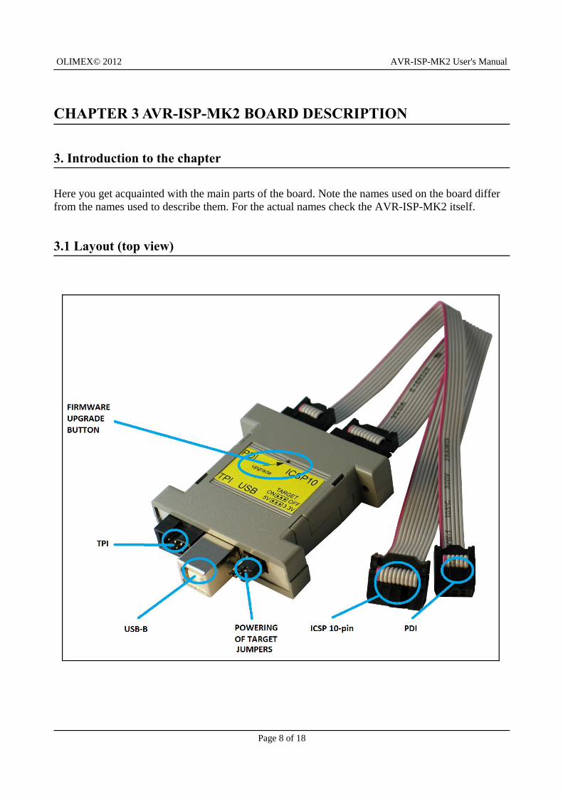
Here you get acquainted with the main parts of the board. Note the names used on the board differ from the names used to describe them. For the actual names check the AVR-ISP-MK2 itself.
3.1 Layout (top view)
Page 8 of 18
OLIMEX© 2012 AVR-ISP-MK2 User's Manual
CHAPTER 4 RECOMMENDED SOFTWARE TOOLS
4. Introduction to the chapter
Here you will find short info on the most popular choices for software that can be used with the AVR programmer.
4.1 AVR-STUDIO in Windows
The most popular choice amongst AVR fans. The IDE has everything you need for software development with AVR under Windows. You can download it from the official Atmel web-site. AVR-ISP-MK2 comes with firmware for AVR-STUDIO in order to use it with AVRDude or Arduino IDE (which uses AVRDude) follow the procedure in next chapter
Note that separately you will have to download the AVRGCC compiler and install it.
4.2 Arduino, AVRDude, Linux
AVR-ISP-MK2 comes with firmware that supports AVR-Studio. In order to use AVR-ISP-MK2 with AVRDude (GCC, LibUSB, Arduino) you need to perform firmware change.
There is a way to use AVR-ISP-MK2 with Arduino/AVRDude using the LibUSB drivers and changing the firmware BUT it is not possible at the moment to use the AVR-ISP-MK2 both at Arduino/AVRDude and AVR Studio. It would depend on you which one you prefer. You need to change the firmware of AVR-ISP-MK2 (using the Atmel Flip program) AND the Windows drivers every time you switch between Arduino and AVR Studio (or vice versa).
How to proceed changing the firmware?
All files needed except for Atmel Flip (which is available at Atmel's web-site for free) should be downloaded from our web site and the AVR-ISP-MK2 page.
1. Connect the device to the USB and with a needle or sharp object press the button on it's back side (the one that the arrow points as "Upgrade"; the LEDs should turn off) which will put the processor in bootloader state - ready for firmware upgrade.
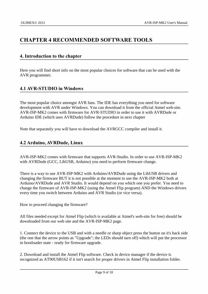
2. Download and install the Atmel Flip software. Check in device manager if the device is recognized as AT90USB162 if it isn't search for proper drivers in Atmel Flip installation folder.
Page 9 of 18
OLIMEX© 2012 AVR-ISP-MK2 User's Manual
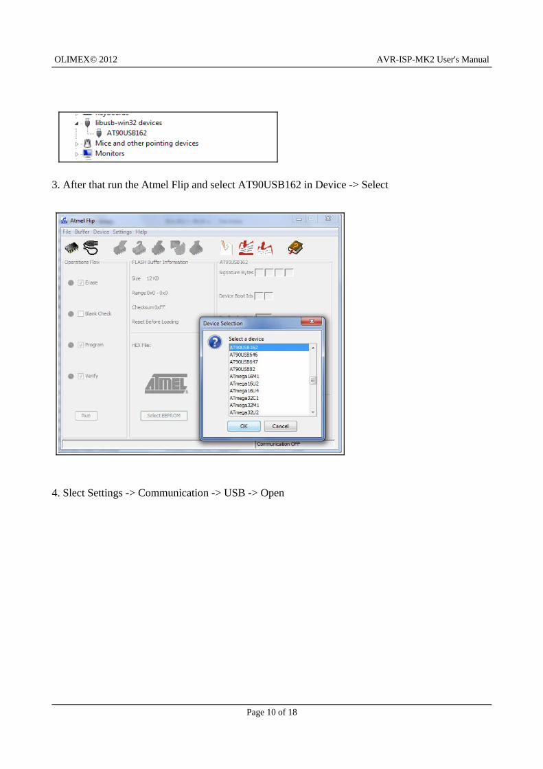
3. After that run the Atmel Flip and select AT90USB162 in Device -> Select
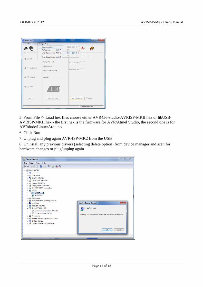
4. Slect Settings -> Communication -> USB -> Open
Page 10 of 18
OLIMEX© 2012 AVR-ISP-MK2 User's Manual
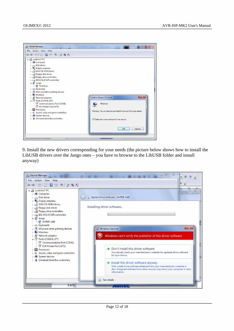
5. From File -> Load hex files choose either AVR456-studio-AVRISP-MKII.hex or libUSB-AVRISP-MKII.hex - the first hex is the firmware for AVR/Atmel Studio, the second one is for AVRdude/Linux/Arduino.6. Click Run7. Unplug and plug again AVR-ISP-MK2 from the USB8. Uninstall any previous drivers (selecting delete option) from device manager and scan for hardware changes or plug/unplug again
Page 11 of 18
OLIMEX© 2012 AVR-ISP-MK2 User's Manual
9. Install the new drivers corresponding for your needs (the picture below shows how to install the LibUSB drivers over the Jungo ones – you have to browse to the LibUSB folder and install anyway)
Page 12 of 18
OLIMEX© 2012 AVR-ISP-MK2 User's Manual
CHAPTER 5 INTERFACES AND HARDWARE
5. Introduction to the chapter
In this chapter are presented the interfaces found on the programmed that can be found on the board. Jumpers functions are described.
5.1 Programming interfaces
AVR-ISP-MK2 has three programming interfaces aiming at different processors
5.1.1 10-pin ICSP
The ICSP (in-circuit serial programming) interface is suitable for programming tinyAVR and megaAVR chips.
Depending on the target you might need https://www.olimex.com/dev/avr-icsp.html since AVR-ISP-MK2 doesn't provide 6-pin ICSP connector. Note it is bought separately.
5.1.2 6-pin PDI
The 6-pin PDI is used for programming AVR XMEGA.
5.1.3 6-pin TPI
The interface used for programming tinyAVR.
5.2 Upgrade firmware button
There is a small hole between the PDI interface and the ICSP10 interface which nests a button below. The button is used to reset the memory. The memory can then be programmed with new firmware. If you wish to update your firmware check if there is newer version in the web and follow the algorithm:
Page 13 of 18
OLIMEX© 2012 AVR-ISP-MK2 User's Manual
1) Connect the programmer to the USB and with a sharp object (needle or pin) press the upgrade pin - it is in a small hole at the back of the board (this will start the bootloader and will turn off the LED, also probably will show a new unrecognized device in device manager for which we will install driver in step 3)
2) Download and install the latest version of "Atmel Flip" software (it can be downloaded from the Atmel's web-site)
3) Open its install folder and update the software of the unrecognized device (usually under "Other devices" tab) with the drivers from folder named "usb"; the device should now be recognized as AT90USB162 under "libusb-win32" tab
4) Start "Atmel FLIP" and click "Select a target device" -> choose AT90USB162
5) Click "Select a Communication Medium" and then USB medium
6) From "File -> load HEX file" choose this HEX (CLICK FOR DOWNLOAD) and click "RUN" in the "Operations Flow" section
7) Disconnect the AVR-ISP-MK2 from the USB and connect it again
Please refer to 4.2 Arduino, AVRDude, Linux for more detailed description.
5.3 Jumpers description
Please note that the two jumpers on the board are PTH (plated-through hole) type.
5.3.1 TARGET jumper
TARGET jumper controls the powering of the target board. If it is in position ON (check the diagram on the back of the plastic cover) it will provide either 3.3V or 5V to the target board (depending on the position of the POWER jumper)
The default position is OFF.
Page 14 of 18
OLIMEX© 2012 AVR-ISP-MK2 User's Manual
5.3.2 POWER jumper
If you have set the TARGET jumper to position ON POWER jumper controls whether 3.3V or 5V are provided to the target board.
The default position is 5V.
5.4 LEDs explained
There are two 3mm LEDs – ORANGE and a double colored GREEN/RED.
Green – when GREEN LED is on – USB connection is activeGreen – GREEN LED on and RED blink - USB connection active and programming activity (erasing, flashing, programming) – unless TARGET is on
Orange – when ORANGE LED is off - TARGET jumper is in position OFFOrange – ORANGE LED on - TARGET jumper is in position on, BLINK means programming activity (erasing, flashing, programming)
Page 15 of 18
OLIMEX© 2012 AVR-ISP-MK2 User's Manual
CHAPTER 6 REVISION HISTORY AND SUPPORT
6. Introduction to the chapter
In this chapter you will find the current and the previous version of the document you are reading. Also the web-page for your device is listed. Be sure to check it after a purchase for the latest available updates and examples.
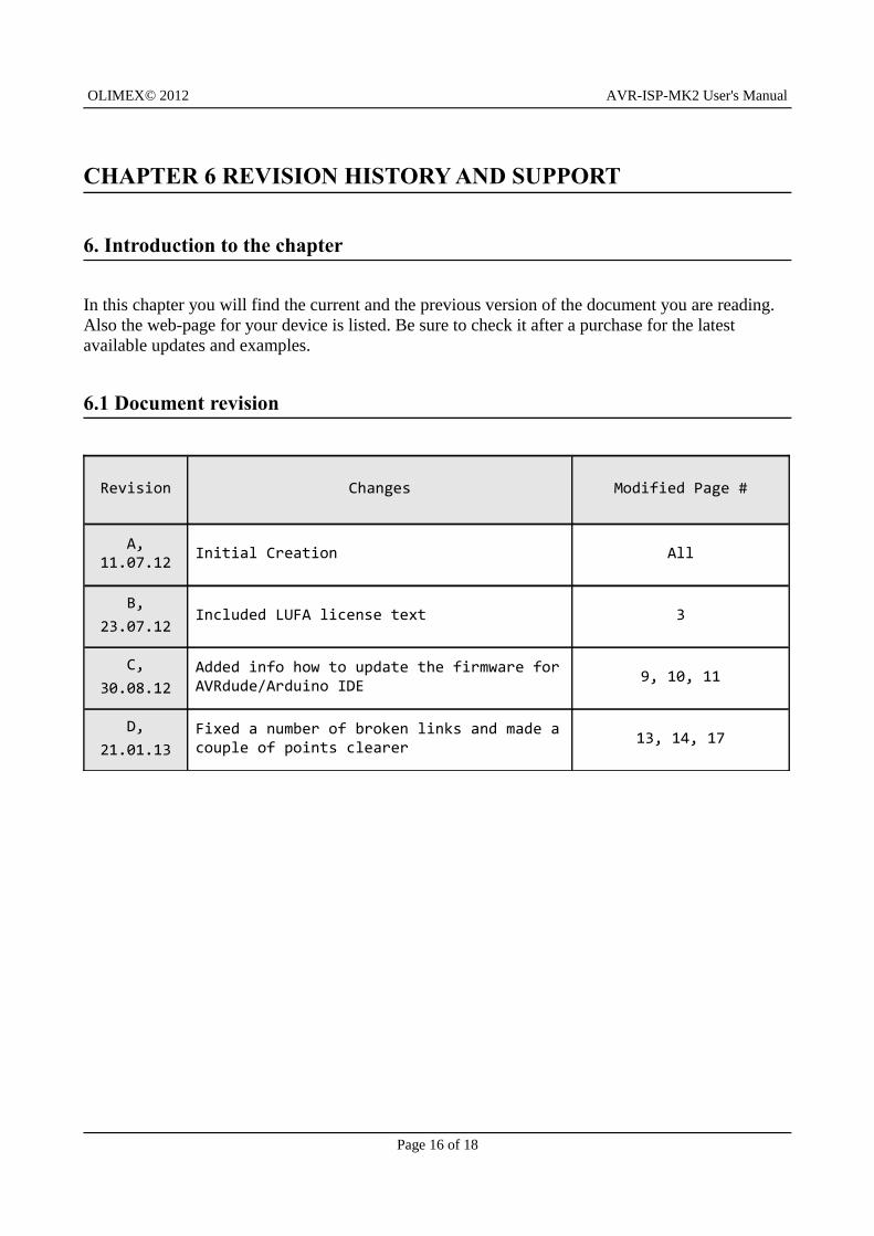
6.1 Document revision
Revision Changes Modified Page #
A, 11.07.12 Initial Creation All
B,23.07.12
Included LUFA license text 3
C,30.08.12
Added info how to update the firmware for AVRdude/Arduino IDE 9, 10, 11
D,21.01.13
Fixed a number of broken links and made a couple of points clearer 13, 14, 17
Page 16 of 18
OLIMEX© 2012 AVR-ISP-MK2 User's Manual
6.2 Useful web links and purchase codes
The web page you can visit for more info on your device is https://www.olimex.com/dev/avr-isp-mk2.html.
You can get the latest updates on the software at: http://www.fourwalledcubicle.com/LUFA.php.
ORDER CODES:
AVR-ISP-MK2 – assembled and tested AVR-ISP compatible programmer
How to purchase Olimex products? You can order from our web-shop or from any of our distributors. The list of official Olimex distributors might be found at: https://www.olimex.com/Distributors/.
Check https://www.olimex.com/ for more info.
Page 17 of 18
OLIMEX© 2012 AVR-ISP-MK2 User's Manual
6.3 Product support
For product support, hardware information and error reports mail to: [email protected]. Note that we are primarily a hardware company and our software support is limited.
Please consider reading the paragraph below about the warranty of Olimex products.
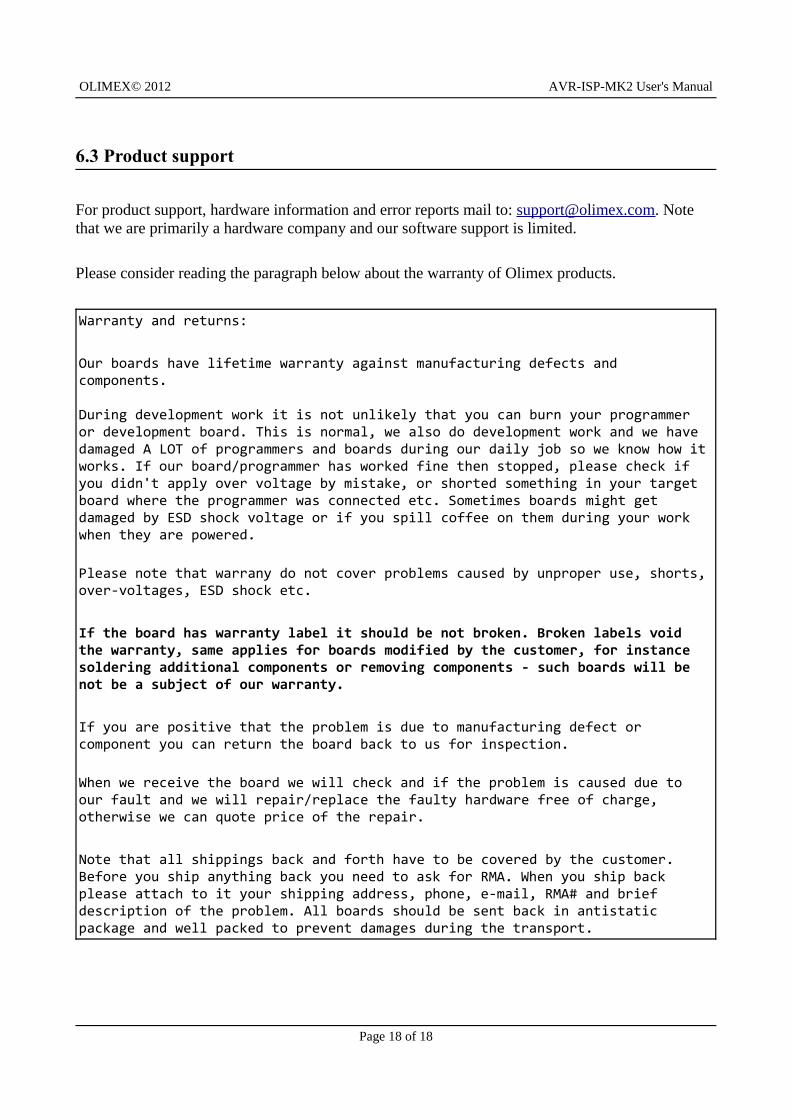
Warranty and returns:
Our boards have lifetime warranty against manufacturing defects and components.
During development work it is not unlikely that you can burn your programmer or development board. This is normal, we also do development work and we have damaged A LOT of programmers and boards during our daily job so we know how it works. If our board/programmer has worked fine then stopped, please check if you didn't apply over voltage by mistake, or shorted something in your target board where the programmer was connected etc. Sometimes boards might get damaged by ESD shock voltage or if you spill coffee on them during your work when they are powered.
Please note that warrany do not cover problems caused by unproper use, shorts, over-voltages, ESD shock etc.
If the board has warranty label it should be not broken. Broken labels void the warranty, same applies for boards modified by the customer, for instance soldering additional components or removing components - such boards will be not be a subject of our warranty.
If you are positive that the problem is due to manufacturing defect or component you can return the board back to us for inspection.
When we receive the board we will check and if the problem is caused due to our fault and we will repair/replace the faulty hardware free of charge, otherwise we can quote price of the repair.
Note that all shippings back and forth have to be covered by the customer. Before you ship anything back you need to ask for RMA. When you ship back please attach to it your shipping address, phone, e-mail, RMA# and brief description of the problem. All boards should be sent back in antistatic package and well packed to prevent damages during the transport.
Page 18 of 18