AVG-HD100 - AVGearavgear.com.au/wp-content/uploads/2015/06/AVG-HD100-User-Manual.pdf1.1 Introduction...
14
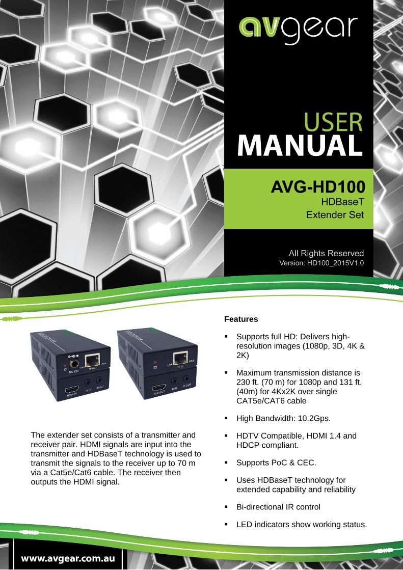
AVG-HD100 Features Supports full HD: Delivers high- resolution images (1080p, 3D, 4K & 2K) Maximum transmission distance is 230 ft. (70 m) for 1080p and 131 ft. (40m) for 4Kx2K over single CAT5e/CAT6 cable High Bandwidth: 10.2Gps. HDTV Compatible, HDMI 1.4 and HDCP compliant. Supports PoC & CEC. Uses HDBaseT technology for extended capability and reliability Bi-directional IR control LED indicators show working status. The extender set consists of a transmitter and receiver pair. HDMI signals are input into the transmitter and HDBaseT technology is used to transmit the signals to the receiver up to 70 m via a Cat5e/Cat6 cable. The receiver then outputs the HDMI signal.
Transcript of AVG-HD100 - AVGearavgear.com.au/wp-content/uploads/2015/06/AVG-HD100-User-Manual.pdf1.1 Introduction...
AVG-HD100
Features
Supports full HD: Delivers high-resolution images (1080p, 3D, 4K & 2K)
Maximum transmission distance is 230 ft. (70 m) for 1080p and 131 ft. (40m) for 4Kx2K over single CAT5e/CAT6 cable
High Bandwidth: 10.2Gps.
HDTV Compatible, HDMI 1.4 and HDCP compliant.
Supports PoC & CEC.
Uses HDBaseT technology for extended capability and reliability
Bi-directional IR control
LED indicators show working status.
The extender set consists of a transmitter and receiver pair. HDMI signals are input into the transmitter and HDBaseT technology is used to transmit the signals to the receiver up to 70 m via a Cat5e/Cat6 cable. The receiver then outputs the HDMI signal.
AVG-HD100
PLEASE READ THIS PRODUCT MANUAL CAREFULLY BEFORE USING THIS PRODUCT.
This manual is only for operational instruction only, and is not to be used in a maintenance capacity. The
functions described in this version are current until March 2015. Any changes of functions and
operational parameters will be updated in future manual versions. Please refer to your dealer for the
latest product details.
Version 1.0 1/3/15
AVG-HD100
SAFETY OPERATION GUIDE
In order to guarantee the reliable operation of the equipment and safety of the user, please abide by the following procedures in installation, use and maintenance:
1. The system must be earthed properly. Please do not use two blade plugs and ensure the alternating power supply ranges from 100v to 240v and from 50Hz to 60Hz.
2. Do not install the switcher in an environment where it will be exposed to hot or cold temperatures.
3. This unit will generate heat during operation, please ensure that you allow adequate ventilation to ensure reliable operation.
4. Please disconnect the unit from mains power if it will be left unused for a long time.
5. Please DO NOT try to open the casing of the equipment, DO NOT attempt to repair the unit. Opening the unit will void the warranty. There are high voltage components in the unit and attempting to repair the unit could result in serious injury.
6. Do not allow the unit to come into contact with any liquid as that could result in personal injury and product failure.
AVG-HD100
TABLE OF CONTENTS
Introduction .............................................................................................................. 1
Introduction to AVG-HD100 .......................................................................... 1.1
Features ....................................................................................................... 1.2
What’s in the Box ..................................................................................................... 2
Introduction of Product Appearance ...................................................................... 3
Appearance of AVG-HD100-T ...................................................................... 3.1
Appearance of AVG-HD100-R...................................................................... 3.2
System Connection .................................................................................................. 4
Usage Precautions ....................................................................................... 4.1
System Diagram ........................................................................................... 4.2
Connection Procedure .................................................................................. 4.3
Application .................................................................................................... 4.4
Twisted Pair Cable Connection .................................................................... 4.5
Specification ............................................................................................................. 5
Supported Resolution ................................................................................... 5.1
Panel Drawings ........................................................................................................ 6
Transmitter ................................................................................................... 6.1
Receiver ....................................................................................................... 6.2
Troubleshooting & Maintenance ............................................................................. 7
AVG-HD100
1. Introduction
1.1 Introduction to AVG-HD100
The extender set consists of a transmitter and receiver pair. HDMI signals are input into the transmitter and HDBaseT technology is used to transmit the signals to the receiver up to 70 m via a Cat5e/Cat6 cable. The receiver then outputs the HDMI signal.
Bi-directional IR is also transmitted across the Cat5e/Cat6 cable. The extender set supports PoC, which can be used to power the receiver via the Cat5e/Cat6 cable. This eliminates the need for power at the receiver end.
1.2 Features
Supports full HD: Delivers high-resolution images (1080p 3D, 4Kx2K)
Maximum transmission distance is 230 ft. (70 m) for 1080p and 131 ft. (40m) for 4Kx2K over single CAT5e/CAT6 cable
High Bandwidth: 10.2Gps.
HDTV Compatible, uses HDMI 1.4 and HDCP compliant.
Supports PoC & CEC.
Uses HDBaseT technology for extended capability and reliability
Bi-directional IR control
LED indicators show working status.
Note: Please use a CAT5e cable with low impedance (Shielded twisted pair will be better and should be well grounded) for good transmission effect. We recommend HDBaseT certified cable.
AVG-HD100
2. What’s in the Box
1 x AVG-HD100 (including TX and RX)
4 x detachable mounting ears
4 x screws
8 x plastic cushions
1 x power adapter (DC 12V 1A)
1 x 5v IR Receiver and 1 x 5v IR Emitter
1 x user manual
Note: Please confirm that the product and the accessories are all included, if not, please contact your dealer.
AVG-HD100
3. Introduction of Product Appearance
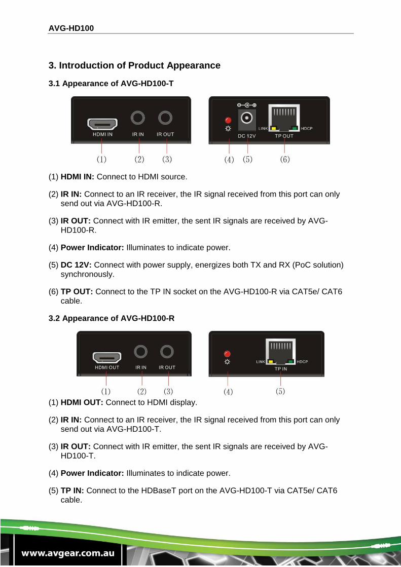
3.1 Appearance of AVG-HD100-T
(1) HDMI IN: Connect to HDMI source.
(2) IR IN: Connect to an IR receiver, the IR signal received from this port can only send out via AVG-HD100-R.
(3) IR OUT: Connect with IR emitter, the sent IR signals are received by AVG-HD100-R.
(4) Power Indicator: Illuminates to indicate power.
(5) DC 12V: Connect with power supply, energizes both TX and RX (PoC solution) synchronously.
(6) TP OUT: Connect to the TP IN socket on the AVG-HD100-R via CAT5e/ CAT6 cable.
3.2 Appearance of AVG-HD100-R
(1) HDMI OUT: Connect to HDMI display.
(2) IR IN: Connect to an IR receiver, the IR signal received from this port can only send out via AVG-HD100-T.
(3) IR OUT: Connect with IR emitter, the sent IR signals are received by AVG-HD100-T.
(4) Power Indicator: Illuminates to indicate power.
(5) TP IN: Connect to the HDBaseT port on the AVG-HD100-T via CAT5e/ CAT6 cable.
AVG-HD100
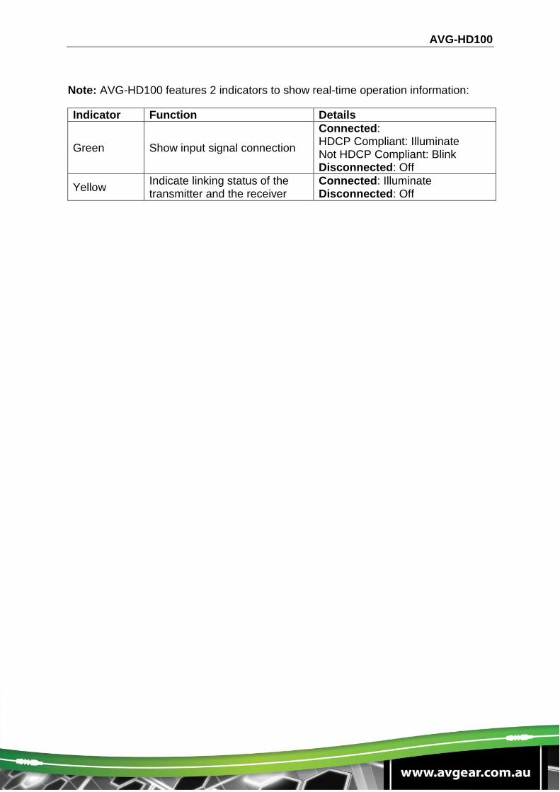
Note: AVG-HD100 features 2 indicators to show real-time operation information:
Indicator Function Details
Green Show input signal connection
Connected: HDCP Compliant: Illuminate Not HDCP Compliant: Blink Disconnected: Off
Yellow Indicate linking status of the transmitter and the receiver
Connected: Illuminate Disconnected: Off
AVG-HD100
4. System Connection
4.1 Usage Precautions
1. System should be installed in a clean environment and has controlled temperature and humidity.
2. All of the power switches, plugs, sockets and power cords should be insulated and safely installed.
3. All devices should be connected before power on.
4. The Cat5e/Cat6 terminations for HDBaseT devices should be a straight-thru TIA/EIA T568B standard.
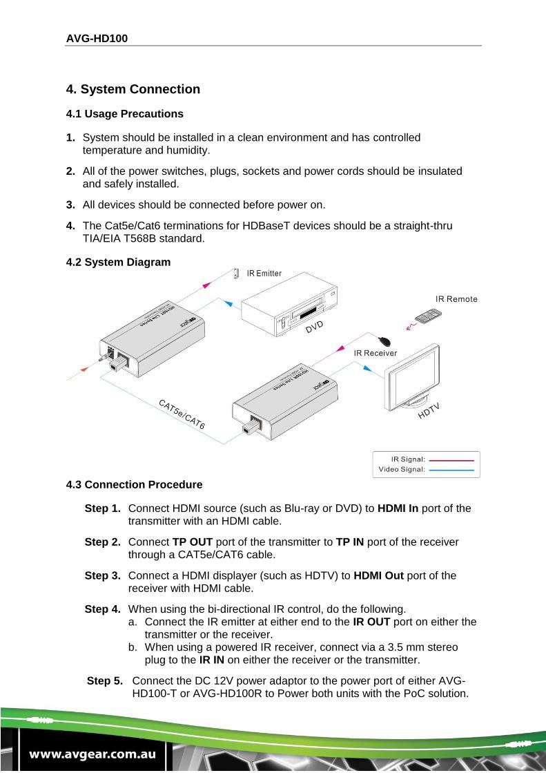
4.2 System Diagram
4.3 Connection Procedure
Step 1. Connect HDMI source (such as Blu-ray or DVD) to HDMI In port of the transmitter with an HDMI cable.
Step 2. Connect TP OUT port of the transmitter to TP IN port of the receiver through a CAT5e/CAT6 cable.
Step 3. Connect a HDMI displayer (such as HDTV) to HDMI Out port of the receiver with HDMI cable.
Step 4. When using the bi-directional IR control, do the following. a. Connect the IR emitter at either end to the IR OUT port on either the
transmitter or the receiver. b. When using a powered IR receiver, connect via a 3.5 mm stereo
plug to the IR IN on either the receiver or the transmitter.
Step 5. Connect the DC 12V power adaptor to the power port of either AVG-HD100-T or AVG-HD100R to Power both units with the PoC solution.
AVG-HD100
4.4 Application
AVG-HD100 has applications in various installations, such as computer IT, signal monitoring, large screen displays, meeting rooms, education, banking & security institutions etc.
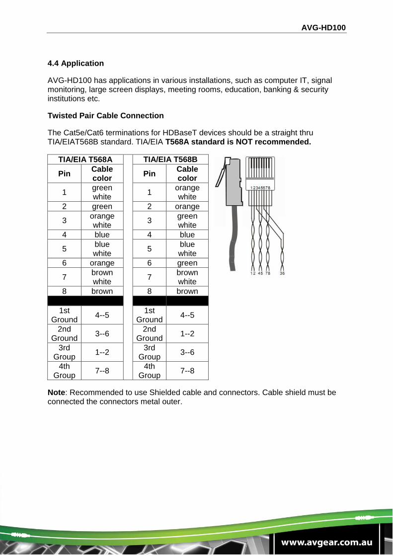
Twisted Pair Cable Connection
The Cat5e/Cat6 terminations for HDBaseT devices should be a straight thru TIA/EIAT568B standard. TIA/EIA T568A standard is NOT recommended.
Note: Recommended to use Shielded cable and connectors. Cable shield must be connected the connectors metal outer.
TIA/EIA T568A TIA/EIA T568B
Pin Cable color
Pin Cable color
1 green white
1 orange white
2 green 2 orange
3 orange white
3 green white
4 blue 4 blue
5 blue white
5 blue white
6 orange 6 green
7 brown white
7 brown white
8 brown 8 brown
1st Ground
4--5 1st
Ground 4--5
2nd Ground
3--6 2nd
Ground 1--2
3rd Group
1--2 3rd
Group 3--6
4th Group
7--8 4th
Group 7--8
AVG-HD100
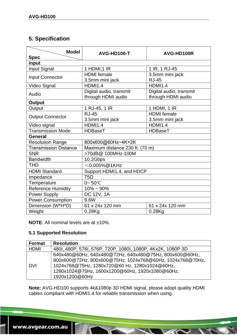
5. Specification
Model Spec
AVG-HD100-T AVG-HD100R
Input
Input Signal 1 HDMI,1 IR 1 IR, 1 RJ-45
Input Connector HDMI female 3.5mm mini jack
3.5mm mini jack RJ-45
Video Signal HDMI1.4 HDMI1.4
Audio Digital audio, transmit through HDMI audio
Digital audio, transmit through HDMI audio
Output
Output 1 RJ-45, 1 IR 1 HDMI, 1 IR
Output Connector RJ-45 3.5mm mini jack
HDMI female 3.5mm mini jack
Video signal HDMI1.4 HDMI1.4
Transmission Mode HDBaseT HDBaseT
General
Resolution Range 800x600@60Hz~4K×2K
Transmission Distance Maximum distance 230 ft. (70 m)
SNR >70dB@ 100MHz-100M
Bandwidth 10.2Gbps
THD <0.005%@1KHz
HDMI Standard Support HDMI1.4, and HDCP
Impedance 75Ω
Temperature 0~ 50℃
Reference Humidity 10% ~ 90%
Power Supply DC 12V, 1A
Power Consumption 9.6W
Dimension (W*H*D) 61 x 24x 120 mm 61 x 24x 120 mm
Weight 0.28Kg 0.28Kg
NOTE: All nominal levels are at ±10%.
5.1 Supported Resolution
Format Resolution
HDMI 480I, 480P, 576I, 576P, 720P, 1080I, 1080P, 4Kx2K, 1080P 3D
DVI
640x480@60Hz, 640x480@72Hz, 640x480@75Hz, 800x600@60Hz, 800x600@72Hz, 800x600@75Hz, 1024x768@60Hz, 1024x768@70Hz, 1024x768@75Hz, 1280x720@60 Hz, 1280x1024@60Hz, 1280x1024@75Hz, 1600x1200@60Hz, 1920x1080@60Hz, 1920x1200@60Hz
Note: AVG-HD100 supports 4k&1080p 3D HDMI signal, please adopt quality HDMI cables compliant with HDMI1.4 for reliable transmission when using.
AVG-HD100
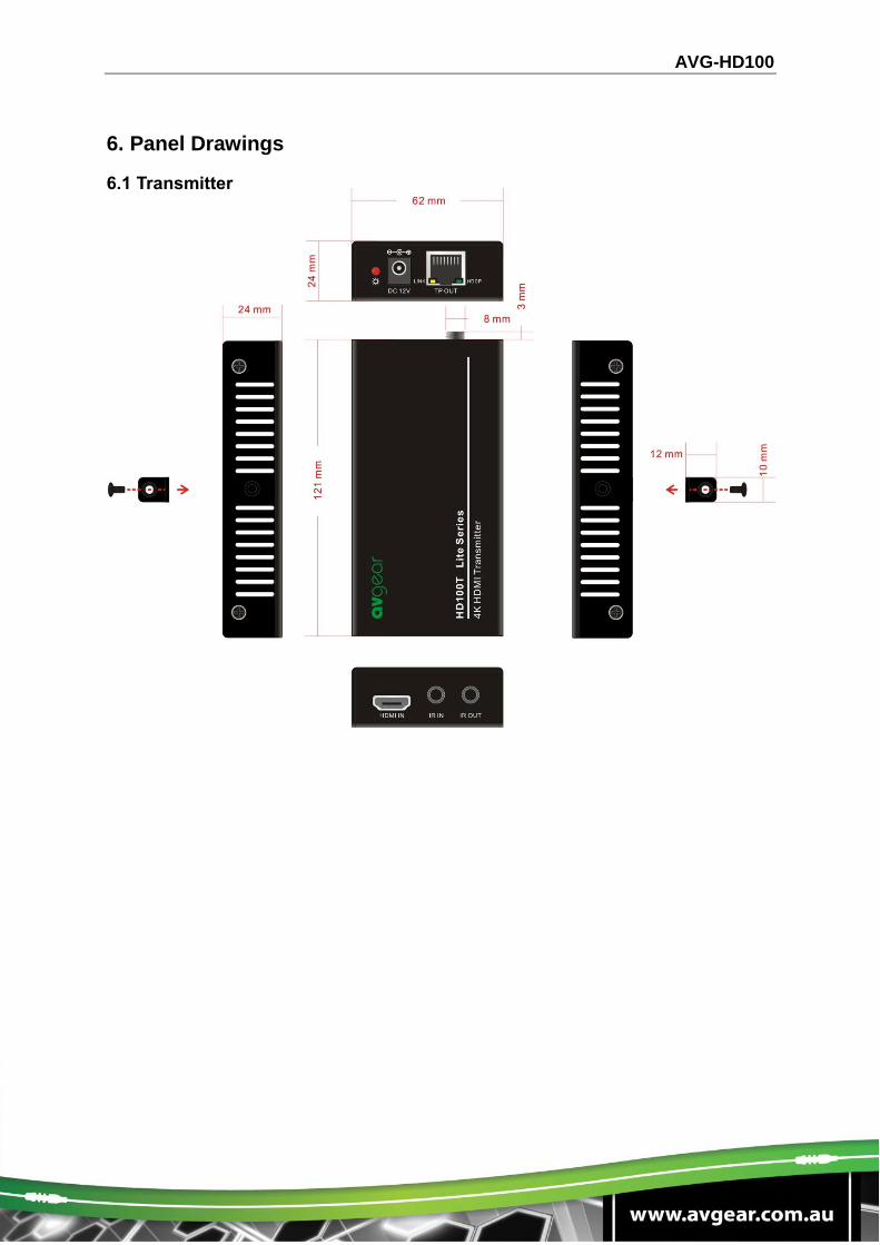
6. Panel Drawings
6.1 Transmitter
AVG-HD100
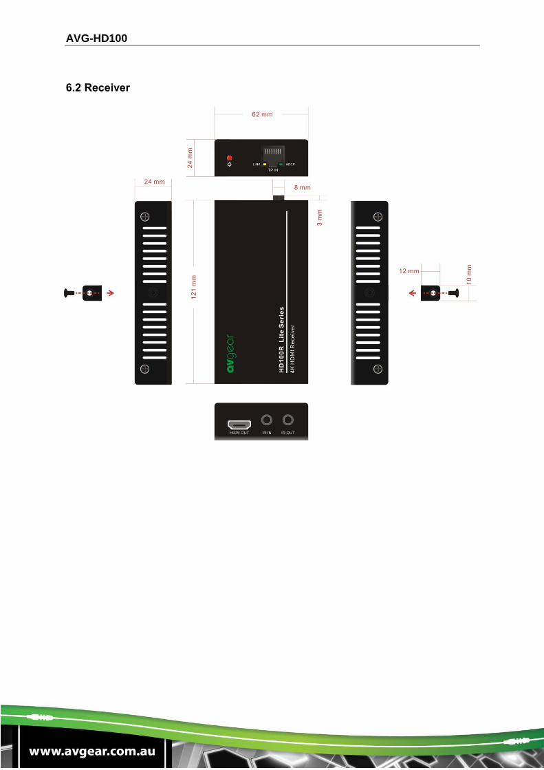
6.2 Receiver
AVG-HD100
7. Troubleshooting & Maintenance
No image on display:
Ensure that the display device has been set to the correct input.
Ensure that the HDMI cables used for both the source/transmitter and the receiver/display are properly connected and are working. Test the HDMI cables directly from a source to display and confirm their operation.
Ensure that the Cat5e/Cat6 cable has not been damaged and that it has been terminated correctly with T568B on both ends. A temporary length of Cat5e/Cat6 can be used for testing to ensure that the devices are all compatible and working properly.
Ensure proper grounding of the power supply.
Known issues with HDMI 1.2 source devices:
Older compatibility (HDMI 1.2) may result in HDBaseT transmission issues.
Color loss or poor picture quality:
Ensure that the HDMI cables used for both the source and transmitter and the receiver and display are properly connected and are of good quality. Test the HDMI cables directly from a source to display and ensure their picture quality.
Ensure proper grounding of the power supply.
If the noise in the picture becomes stronger or picture quality becomes worse when connecting the video connectors, this may be due to improper grounding.
Check the grounding and make sure all the components are properly grounded to a common ground. Improper grounding may cause damage to the receiver.
If your problem persists after following the above troubleshooting steps, seek further help from authorized dealer or our technical support.