
autres, la classification tarifaire.
80
RESTRICTED AIR/TSC/W/31 1er avril 1982 ACCORD GENERAL SUR LES TARIFS DOUANIERS ET LE COMMERCE Distribution spéciale Accord r e l a t i f au commerce des aéronefs c i v i l s SOUS-COMITE TECHNIQUE Renseignements additionnels concernant certains produits CEE La CEE a fait parvenir au secrétariat la communication ci-après en date du 17 mars 1982. On y trouvera sept fiches distinctes contenant des renseignements additionnels sur quelques-unes des propositions présentées par la CEE. Des renseignements additionnels concernant d'autres propositions émanant de la CEE seront communiqués sous peu. Les fiches ci-jointes peuvent faire l'objet de modifications touchant, entre autres, la classification tarifaire.
Transcript of autres, la classification tarifaire.

RESTRICTED
AIR/TSC/W/31 1er avril 1982 ACCORD GENERAL SUR LES TARIFS
DOUANIERS ET LE C O M M E R C E Distribution spéciale
Accord re la t i f au commerce des aéronefs c iv i l s
SOUS-COMITE TECHNIQUE
Renseignements additionnels concernant certains produits
CEE
La CEE a f a i t parvenir au secrétariat la communication ci-après en date du 17 mars 1982. On y trouvera sept fiches distinctes contenant des renseignements additionnels sur quelques-unes des propositions présentées par la CEE.
Des renseignements additionnels concernant d'autres propositions émanant de la CEE seront communiqués sous peu.
Les fiches ci- jointes peuvent fa i re l 'objet de modifications touchant, entre autres, la classification tar i fa ire.

AIR/TSC/W/31 Page 2
FICHE DE PROPOSITION 1/82 : N C C D : Voir rubrique 2
1 - Désignation du produit -
Ensembles, sous-ensembles^parties et_£ièces_détachées (parts), c'est-à-dire élé
ments et rechanges spécifiques pour aéronefs civils, identifiables par un numéro
de codification, suivant l'ATA 100, donné par le constructeur et repris dans le
catalogue illustré (I.P.C. où I.P.L. (1)) des aéronefs, des moteurs ou des équi
pements et systèmes de bord.
Ces éléments et rechanges sont des constituants des aéronef s, des moteurs
ou des équipements et systèmes de bord, ils sont nécessaires à la construction,aux
entretiens périodiques et aux réparations.
Sont exclues de cette définition les parties et pièces détachées non
spécifiques, d'usage général.
NOTA : Les utilisateurs sont tenus contractuellement, et en particulier pour
des raisons de sécurité, d'approvisionner ces rechanges durant toute la vie des
matériels. Toute substitution de pièce doit recevoir l'accord préalable du cons
tructeur.
Supprimer les droits de douane sur les moteurs, les équipements et les
systèmes de bord des aéronefs civils et les maintenir sur les éléments et parties
et pièces détachées /rechanges spécifiques est une mesure contraire à l'objectif
de l'Accord relatif au commerce des aéronefs civils. C'est une mesure discrimi
natoire, dissuasive et pénalisante par ses effets à moyen et long termes qui va
à 1'encontre d'une concurrence équitable entre matériels de même nature.
2 -Classification tarifaire - Demande de_levéè_de_l^exclusion_actuelle -
NCÇD TSUS T. Can.
73-38
84-07
84-08
84-10
84-13
84-12
84-15
84-18
84-21
84-22
84-59
P.C. : Illustreted Parts Catalogue de l'aéronef
P.L. : Illustreted Parts List de l'équipement
ensembles, sous-ensembles,
parties et pièces détachées
actuellements exclus de
l'Accord aux positions :

( ) ( ) ( ) (
ensembles, sous -ensembles , )
p a r t i e s e t p i èces dé tachées )
exclus de l 'Accord aux (
p o s i t i o n s : ( )
NCCD 84-63 85-01 85-08
85-12
85-14
85-15
85-17
90-14
90-18
90-29
( ( p a r t i e ) ) ( des ) ( ( 90-24)
( ( 9° Z / ) ) ( 90-'28) ( ( 94-01)
TSUS
AIR/TSC/W/31 Page 3
T. Can
3 - Exemple d'utilisation -
Fabrication, entretien et réparation d'aéronefs civils au sens donné
par l'Article 1 de l'Accord relatif au commerce des aéronefs civils.
Voir fiches annexées illustrant l'identification des rechanges.
4 - $ e s c r i p ^ i o n _ t e ^ h n i g u e "
Sans obje t - , v o i r f i c h e s s u s - v i s é e s .
5 - Importance d u _ b e s o i n ~
élevées.
Très important durant toute la vie de l'aéronef, concerne des valeurs
6 - Obstacles au détournement de destination -
- -
ZSJC-l' ÎŒSÏ)
• Spécificité technique ) Matériels spécifiques, parfaitement iden-
, . ,. , \ tifiânlés; répondant à des exigences parti-
( culières, à des normes nationales et/ou • Sources s p é c i a l i s é e s
4 P e r s o n n a l i s a t i o n ' '
) lité. * Prix élevés
* rersoanaiisatiwu C internationales et à des contrôles de qua-
) Problème de prix. '.iwp 3supi*3t/eno: '•- »• »»(,**'
• csusncîà's ^3 i3x313 ,
TION SUE
: 29 .12 .81 : 15. 2.82 : iSmktWM. î ^'"slivniB^'ïïoîH^ïTIfiP^ ^ M n

AIR/TSC/W/31 Page 4 FICHE DE PROPOSITION 2/82 : N C C D : Voir rubrique 2
1 - Désignation du produit -
"Robinetterie1 de bord ou plus spécifiquement équipement de distribution, de régu-
gulation pour circuits de fluides, ensembles, sous-ensembles leurs parties et piè
ces détachées spécifiques identifiables. •
2 - Classement tarifaire - Position_nouyelle_demandée -
NCCD TSUS T. Can.
•Robinetterie" 84-61
(Dispositifs de contrôle et/ou de corn-) 90 - 24 ) (mande lorsque ceux-ci agissent à dis-( ) (tance ) 90 - 28 )
3/4 - Exemple d'utilisation - Description technique -
La circulation d'un fluide entre la source d'énergie et les systèmes de
bord fait intervenir un certain nombre d'organes plus ou moins complexes de dis
tribution : robinet, vanne, valve, distributeur, limiteur de débit, diviseur de
débit, répartiteur de débit, sélecteur, détendeur, soupape, clapet, etc .
Leur organe de commande, inclus ou non à l'équipement, peut être mécani
que, électrique, hydraulique ou pneumatique, il peut fonctionner soit en boucle
fermée, soit en boucle ouverte (feed back ou non feed back).
Ces équipements se retrouvent dans les systèmes de bord des aéronefs :
- circuits de carburant (remplissage des réservoirs et alimentation des moteurs
- circuits hydrauliques (commandes de vol, atterrisseurs, aérofreins, freins de-roues, commandes de portes, et autres servitudes de bord),
- circuits pneumatiques (pressurisation et conditionnement d'air : poste de pilotage, cabines passagers, soutes et compartiments divers, distribution d'oxygène, dégivrage....).
Ces équipements de distribution font l'objet de normes aéronautiques qui
les distinguent des autres équipements similaires, ils ont en conséquence une spé
cificité aéronautique incontestable et reconnue à travers leur certification ou
qualification délivrée par les Autorités aéronautiques gouvernementales (FAA, DGAC, ;
AIR/TSC/W/31 Page 5
5 - Importance du besoin -
Ces matériels équipent, comme exposé ci-dessus, les circuits de carburant,
les circuits hydrauliques et les circuits pneumatiques des aéronefs, leurs fonctions
sont vitales pour la sécurité.
De nombreux matériels de l'espèce équipent les aéronefs, la valeur globale de
ceux montés sur un avion gros transporteur (vide body) peut être estimée à un mini
mum de 1 million de francs.
6 - Obstacle au détournement de destination -
* Spécificité technique
f Sources spécialisées
* Personnalisation
* Prix élevés
Matériels spécifiques, parfaitement identi-
* fiables,répondant à des exigences particulières,
) à des normes nationales et/ou internationales
\ et à des contrôles de qualité très contraignants.
( )
Problème de prix..
'
si . •
: :.; ;" i-Wim
LDITION
ISSUE : 29.12.81 :
• -
-
?•"'.,.
• • • • • •
_ ^ _ ^ ^ _ _ ^ ^ _ _ _ ^
AIR/TSC/W/31 Page 6
FICHE DE PROPOSITION 3/82 : N C C D : Vo i r rubr ique 2
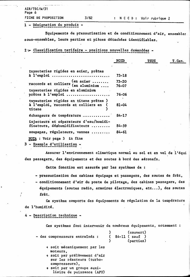
1 - Désignation du produit -
Equipements de pressurisat ion e t de conditionnement d ' a i r , ensembles
sous-ensembles, leurs par t ies e t pièces détachées ident i f iab les .
2:+ Classification Çarifaire_- positions nouvelles demandées -
NCCD TSUS T. Can.
tuyauteries rigides en acier, prêtes à l'emploi 73-18
. ... (en acier 73-20 raccords et colliers ( e Q alufflinium _ . 76_07
tuyauteries rigides en aluminium prêtes à l'emploi 76-06
tuyauteries rigides en titane prêtes ) à l'emploi, raccords et colliers en ( 81-04 titane )
échangeurs de température 84-17
injecteurs et séparateurs d'eau/humidificateurs, déshumidificateurs 84-59
soupapes, régulateurs, vannes 84-61
NÇ34 : Voir page 3 in fine
3 - Exemple d'utilisation -
Assurer l'environnement climatique normal au sol et en vol de l'équi
des passagers, des équipements et des soutes à bord des aéronefs.
Cette fonction est assurée par les systèmes de :
- pressurisation des cabines équipage et passagers, des soutes de fret,
- conditionnement d'air du poste de pilotage, des cabines passagers, des
équipements (soutes radio, armoires électroniques, e t c . ) , des soutes
fret.
Ce système comporte des équipements de régulation de la température
de l'humidité.
4 - Description technique -
Ces systèmes font intervenir de nombreux équipements, notamment
) (couvert) ( 84-11 ( sauf ) ) (parties)
) (couvert) - des compresseurs entraînés : ( 84-11 ( sauf )
4 soit mécaniquement par les moteurs,
* soit par prélèvement d'air sur les réacteurs (turbocompresseurs),
+ soit par un groupe auxiliaire de puissance (APU)
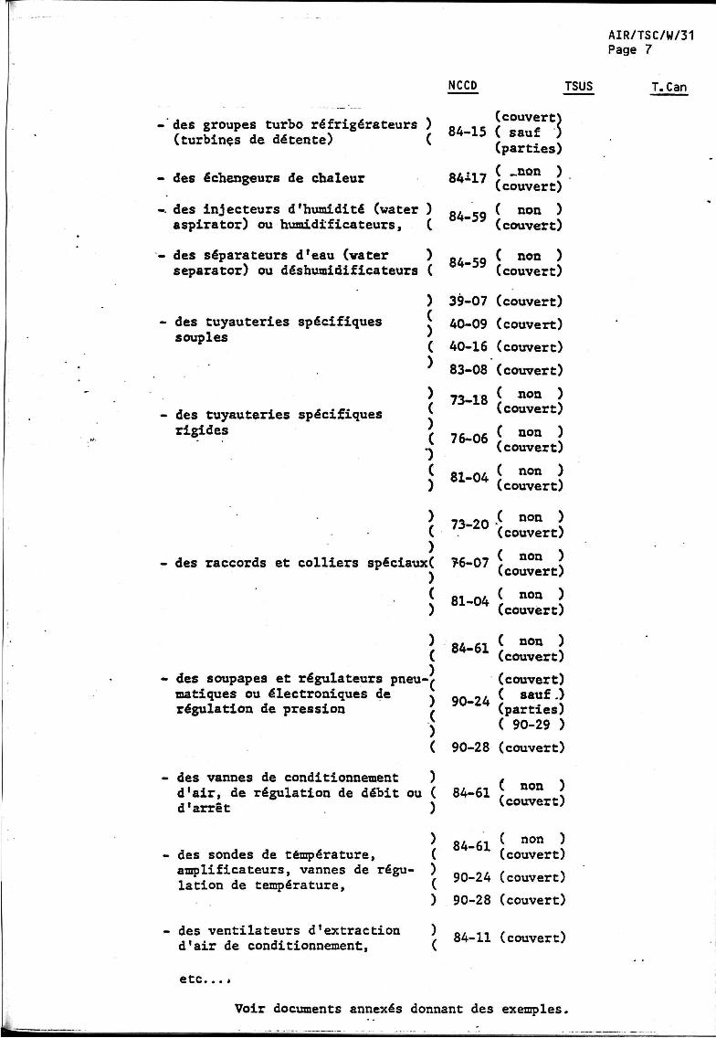
AIR/TSC/W/31 Page 7
NCCD TSUS T.Can
-'des groupes turbo réfrigérateurs ) (turbinçs de détente) (
• des échangeurs de chaleur
des injecteurs d'humidité (water aspirator) ou humidificateurs,
des séparateurs d'eau (vater separator) ou déshumidificateurs
des tuyauteries spécifiques souples
des tuyauteries spécifiques rigides
- des raccords et colliers spéciaux
des soupapes et régulateurs pneumatiques ou électroniques de régulation de pression
des vannes de conditionnement d'air, de régulation de débit ou d'arrêt
des sondes de température, amplificateurs, vannes de régulation de température,
des ventilateurs d'extraction d'air de conditionnement,
(couvert) 84-15 ( sauf )
(parties)
84^17
84-59
84-59
( _non ) (couvert)
( non ) (couvert)
( non ) (couvert)
39-07 (couvert)
40-09 (couvert)
40-16 (couvert)
83-08 (couvert)
( non ) (couvert)
73-18
76-06
81-04
73-20
76-07
81-04
84-61
90-24
( non ) (couvert)
( non ) (couvert)
( non ) (couvert)
( non ) (couvert)
( non ) (couvert)
( non ) (couvert)
(couvert) ( sauf.) (parties) ( 90-29 )
90-28 (couvert)
84-61
84-61
( non ) (couvert)
( non ) (couvert)
90-24 (couvert)
90-28 (couvert)
84-11 (couvert)
etc.
Voir documents annexés donnant des exemples.

AIR/TSC/W/31 Page 8
5 - Importance du besoin -
Ces matériels sont très importants, ils assurent les conditions de vol
des aéronefs, ils sont vitaux pour la sécurité des équipages et des passagers
ainsi que pour le bon fonctionnement des instruments et systèmes de bord.
La valeur des systèmes de pressurisation et de conditionnement d'air
représente approximativement 11 7. de la valeur des systèmes de l'aéronef (cel
lule, moteurs et A P TJ exclus).
€ - Obstacles au détournement de destination -
* Spécificités techniques
* Sources spécialisées
4- Personnalisation
* Prix élevés
Matériels spécifiques, parfaitement id€
tifiables, répondant à des exigences par
ticulières, à des normes nationales et/ou
internationales, à des essais de conform!
té qui conditionnent la certification des
aéronefs.
Problème de prix.
Actuellement dans le domaine "pressurisation et conditionnement d'air"
ne sont couverts par l'Accord aéronautique GATT que les "groupes pour le condi
tionnement de l'air comprenant, £|H2i£_SS»H2_££Hi.£2EBE» "^ ventilateur à moteur
"et des dispositifs propres à modifier la température et l'humidité, à l'exception
"de leurs parties et pièces détachées", ce qui est loin de couvrir les échanges
entre pays signataires. A titre d'exemple, aucun appareil de ce type "réunis en
un seul corps" n'équipe les avions de transport de plus de 15 Tonnes.
Les demandes visées au § 2 sont illustratives de matériels entrant dans
les équipements de pressurisation et de conditionnement d'air choisis comme exemple
Bien entendu, la demande d'extension porte sur toutes les tuyauteries rigides en
acier, en aluminium et en titane prêtes à l'emploi et reprises aux 73-18, 76-06
et 81-04. Il en est de même pour les échangeurs de température du 84-17 et la"robi-
netterie"du 84-61 que l'on retrouve dans divers systèmes des aéronefs civils.
JOTA : Voir fiches sur : - ensembles, sous-ensembles, parties et pièces détachées,
- robinetterie.
EDITION
ISSUE 30,12.81

AIR/TSC/W/31 Page 9
NORMALISATION DE LA DOCUMENTATION TECHNIQUE DES CONSTRUCTEURS
SYST/ SOUS-SYS/ ,'CHAP. SECTION
21
-00 -10
-20
-30
-40
-50
-60
-70
TITRE
CONDITIONNE-MENT D'AIR
Généralités Compression
Distribution
Régulation de la pression
Réchauffage
Refroidissement
Régulation de la température
Régulation de l'humidité et de la contamination de l'air
DEFINITION
Equipements et composants assurant la pressurisation, le réchauffage, le refroidissement, la régulation de l'humidité, le filtrage et la purification de l'air utilisé pour ventiler les zones pressurisées du fuselage. Comprend le compresseur de cabine, le refroidissement des équipements, le réchauffeur, le circuit carburant du réchauffeur, la turbine de détente, les vannes, manches à air, canalisations,, etc.
Partie du système et de ses commandes qui fournit l'air comprimé à la cabine. Comprend, par exemple, les commandes et contrôles des compresseurs, le câblage, etc. Ne comprend pas les comma'ndes'et contrôles du circuit de pressurisation cabine. Partie du système servant à l'admission et à la distribution de l'air. Comprend les circuits de refroidissement des armoires d'équipements et, par exemple, les ventilateurs, manches à air, canalisations, prises d'air, clapets d'arrêt, câblage, etc. Ne comprend pas ies vannes servant à la régulation de pression et de température. Partie du système servant à la régulation de la pression à l'intérieur du fuselage. Comprend, par exemple, les vannes de régulation, soupapes de décharge, dispositifs de signalisation/contrôle, commutateurs, amplificateurs, câblage, etc. Partie du système et de ses commandes qui fournit l'air réchauffé à la cabine. Comprend, par exemple, les réchauffeurs, circuit carburant et commandes, circuits d'allumage et de signalisation/contrôle, liés au fonctionnement des réchauffeurs, le câblage, etc. Ne comprend pas les circuits de régulation et de signalisation/contrôle de la température.
Partie du système et de ses commandes qui fournit l'air frais à la cabine. Comprend, par exemple, le groupe de réfrigération, les circuits de signalisation/contrôle liés au fonctionnement du radiateur, le câblage, etc. Ne comprend pas les circuits de régulation et de signalisation/contrôle de la température. Partie du système servant à la régulation de la température de l'air à l'intérieur de la cabine. Comprend, par exemple, les vannes de régulation, . sondes de température, commutateurs, dispositifs de signalisation/contrôle, amplificateurs, câblage, etc. Partie du système servant à la régulation de l'humidité de l'air, à contrôler le degré de concentration d'ozone, à filtrer les déchets radioactifs présents dans l'air conditionné et à purifier l'air à l'aide de désodorisants, inseccicides, etc.

--m #• •
^310 ^ i r c©ndStSoBiitîîg system 21 CONTENTS 1 AIR GENERATION AND
TEMPERATURE CONTROL 2 AIR DISTRIBUTION IN FLIGHT
DECK 3 AIR DISTRIBUTION IN
PASSENGER CABIN 4 GALLEY AND TOILET
VENTILATION 5 ELECTRIC AND ELECTRONIC
EQUIPMENT VENTILATION 6 CABIN PRESSURE CONTROL
SYSTEM 7 CARGO COMPARTMENT
HEATING AND VENTILATION
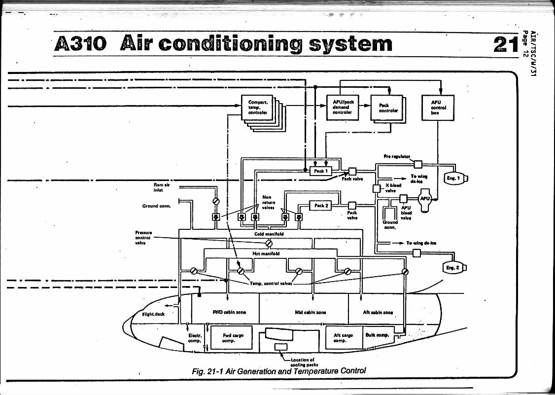
1 AIR GENERATION AND TEMPERATURE CONTROL (See Fig. 21-1) The A310 system philosophy and
major components are similar to those of the A300.
The air supply is taken from the engine bleed and alternatively, from the APU. Two high pressure supply points are also provided. Conditioned air can also be supplied direct to the cabin air distribution by a low pressure ground connection. A ram air inlet is also provided for fresh air ventilation in flight when the packs
are not operating.
The fresh air quantity required for air conditioning is defined to supply 12 cubic feet per minute per occupant (standard seat layout) and also to meet the heating and cooling requirements.
The system may be subdivided into two identical air conditioning groups and a temperature control subsystem.
Each air conditioning pack incorporates a three wheel "Bootstrap" air cycle machine with an air-to-air heat exchanger. This pack is identical to that of the A300. It is known to be reliable and needs little maintenance.
The packs and all' associated equipment are installed (as on A300) under the central wing box. They are accessible via the main landing gear wheel well.
The air intakes to the heat exchangers are equipped with flaps to protect the heat exchangers against dirt injection during take-off and landing.
Upstream of each pack, a pack valve is fitted which can operate in two modes : normal mode which provides the specified performance of the air
conditioning system, and economic mode which enables the crew, for fuel economy, to reduce the bleed air demand whenever the loading conditions of the aircraft permit.
The conditioned air (temperature, humidity) from the two packs is fed into a common cold air manifold. Hot air is supplied directly from tapping downstream of the bleed air flow control valves via a pneumatic pressure regulating valve into a hot air manifold.
The temperature may be automatically or manually regulated in four zones (flight deck, forward, mid and aft cabin) by varying the pack outlet temperature and adding trim (hot) air.
In automatic operation, the temperature at the pack outlets (cold air) is regulated as follows :
- one pack only operating : the pack discharge temperature is controlled by the zone requiring the lowest inlet temperature.
- two packs operating : if the flight deck requires the lowest inlet temperature, pack 1 is controlled by the flight deck and pack 2 by the cabin zone requiring the lowest inlet temperature. If one of the three cabin zones requires the lowest inlet

A310 Mr condjijaonJBig system 21 temperature, packs 1 and 2 are controlled by this zone.
If there is a failure in the automatic control, the outlet temperature of either pack can be varied manually on the pack temperature panel.
The air temperature in each zone is normally adjusted to the selected valve by automatic control of the trim air valves. These may also be positioned by manual selection on the overhead panel if the automatic control system fails.
An APU and pack temperature demand controller, in automatic mode, acts as an interface between the zone temperature controller and the pack temperature controllers. It also acts as an interface between total system demand and the APU electronic control when the APU is the air supply source.
MCMMtci PACK TEMP IIMP CH VtlVC
•v > 0> M
u i
A310 Air c©iîdlitioning system 21 T) » . 01 M IO 50 n) ••».
H - » </>
" \ »
Ram air inlet
Ground conn.
Compart. temp. contrôler 1 APU/pack
demand contrôler
Pack contrôler
APU control pox
élfelrQ Pre regulator
33
^ >— Location of
cooling packi
Fig. 21-1 Air Generation and Temperature Control

Â310 Mw condifioming system 21 2 AIR DISTRIBUTION IN FLIGHT
D E C K (See Fig. 21-2)
The flight deck air distribution system is similar to that of the A300. Air is supplied along the left hand side of the aircraft to the following outlets :
- from the ceiling at the rear of the flight deck,
- below the front windscreen windows,
- at floor level on the*left hand side of the flight deck.
At these three points, the airflow is manually adjustable in quantity.
- on the left hand side of the Captain's station,
- on the right hand side of the First Officer's station,
- near the cei l ing at 3rd occupant stat ion, 2 outlets.
For these four la t ter points, the airf low 1s adjustable in quantity and direct ion.
Extracted a i r is passed out of the f l i gh t deck Into the electronic compartments.
Foot warmers (optional)
Airflow adjustable •
Fig. 21-2 Flight Deck Air Distribution
-o > ID JO n >»
- i -» C/» U4 r>
w

• - * i f # 1
A310Air'conditioning system 21 •o >
*» o
3 AIR DISTRIBUTION IN PASSENGER CABIN
Cold air supplied from the packs is split into three riser ducts, one per temperature zone. (See Fig. 21-3).
Hot air is added in the required proportion in the riser ducts, which pass up between the cabin frames and furnishing panels to the cabin ceiling.
The ducted fresh air is then mixed with the recirculated air in the cabin ceiling main supply ducts, before it is distributed in the cabin by ducts above the lateral hatracks. (See Fig. 21-4).
The fresh air to recirculated air proportion is 60 % to 40 % in normal mode.
Recirculated air is supplied to the main air supply ducts by three electric fans, one in each temperature zone. Extracted air is passed out of the cabin through vents in the walls near the floor.
Tappings from the main supply ducts are taken to supply air for the individual ventilation of the toilets and galleys. Restrictors are installed in the supply ducts downstream of the tapping points to raise the pressure level for correct
functioning of the Individual air outlets.
Individual ventilation for the passenger compartment is provided as an option. (See F1g. 21-5)
The air for the Individual ventilation Is taken from the main cabin fresh air supply via separate distribution ducts in the cabin ceiling through the hatracks to the Individual air outlets provided In the passenger service units. The airflow from the Individual air outlets is adjustable 1n quantity and direction.
1/4
Rising ducts
@ ® @ Galley and toilet , | individual ventilation
"^sfitâli
Forward temperature zone Central temperature zone Rear temperature zone
Fia. 21-3 Cabin Air Distribution (general Layout)

A310 Ékw corcdBtBonEng system 43a •
F/g. 27-4 A/r Circulation
Supply duct
Fig. 21-5 Cabin Air Distribution (Optional Individual Air Outlets)
T> > Q> t-i
CQ so n -»
-t - » CO
a

. - - * m .
A310 Air condit ioning system 21 01 t-* ta » » »».
H - » CO O n
4 GALLEY AND TOILET VENTILATION (Sce f 1 g 21.6)
The galley and toilet venti» lation system is an entirely new design for the A310.
Air is supplied to the toilets and galleys from an individual ventilation system. In addition, air
OJ
from the cabin can enter the toilets through inlet grills.
Air 1s extracted from the toilet boxes, toilet bowls and galleys via a pipe In the cabin roof. This pipe has many adaptors provision for installation of galleys and toilets
1n various positions in the cabin. Cabin pressure differential provides extraction during flight, while a fan is used when the aircraft Is on the ground. All extracted air Is passed directly overboard at a point located on the bottom of the aircraft, aft of the bulk cargo compartment.
Basis L+G extraction duct
Toilet tank vent
Shut-off valve
Fig. 21-6 Galley and Toilet Ventilation

A310 Mv G&nûltlomng system 21 5 ELECTRIC AND ELECTRONIC
EQUIPMENT VENTILATION (See Fig. 21.7)
Ventilation is provided for the main equipment racks complying with ARINC 600 (or ARINÇ 404A in some cases). Some other equipments in the main racks, as well as the pedestal and the flight deck panels are ventilated by air blown over the equipments and ambient air is extracted from around the equipment.
The air is drawn through a dust separator and filter by one of two identical blowing fans. The«other fan is available as a standby. One of these fans is normally running whenever electrical power is available on board the aircraft. Automatic switch over to the other fan occurs after each flight or in case of failure (the latter case being indicated in the flight deck).
Additional ventilation is provided from a tapping in the flight deck fresh air duct when the air conditioning system is running. This air is not filtered.
The air through and over the equipment is normally sucked out by an extractor fan and,via two valves» passed overboard or into the forward cargo underfloor area to provide floor heating. The position of these two valves is controlled automatically
depending on the situation (ground/ /• flight, cold/hot day). The overboard valve can also be controlled manually. Battery ventilation is provided by a separate small fan, and the ducting is separated from the main electrical and electronic ventilation system.
A number of smoke detectors are placed in the system. Smoke detection is assisted by a flight deck "sniffer" for the smoke emergency shelf.
An optional refrigeration unit, complete with an additional cooling fan, is available for main equipment cooling on the ground. It is intended that this unit can be used when the APU is not running.
VENT EQPT C00L
EXTRACT VALVE
OVBO U / F L O O R C B
FAULT
OFF
MODE SEL
FLOW
OVBD. s AVIONICS
BIDWERS
FLOW
ALTN J£r&>
-O 3» 0) HI (O TO n >*
- i - » c/> ->l o
Ul

&m % « i
Â310 Mv condlt5©nirag system 21 -o > «o » «0 -«.
H -» M 00 n
l A l
m ^ ^ s s s . ' r f j h r r t,' Aircraft skin
11 \_Optional refrigeration unit
1 Flight deck fresh air duct
\ Restrictor
F/g. 21-7 Electronic Bay Ventilation

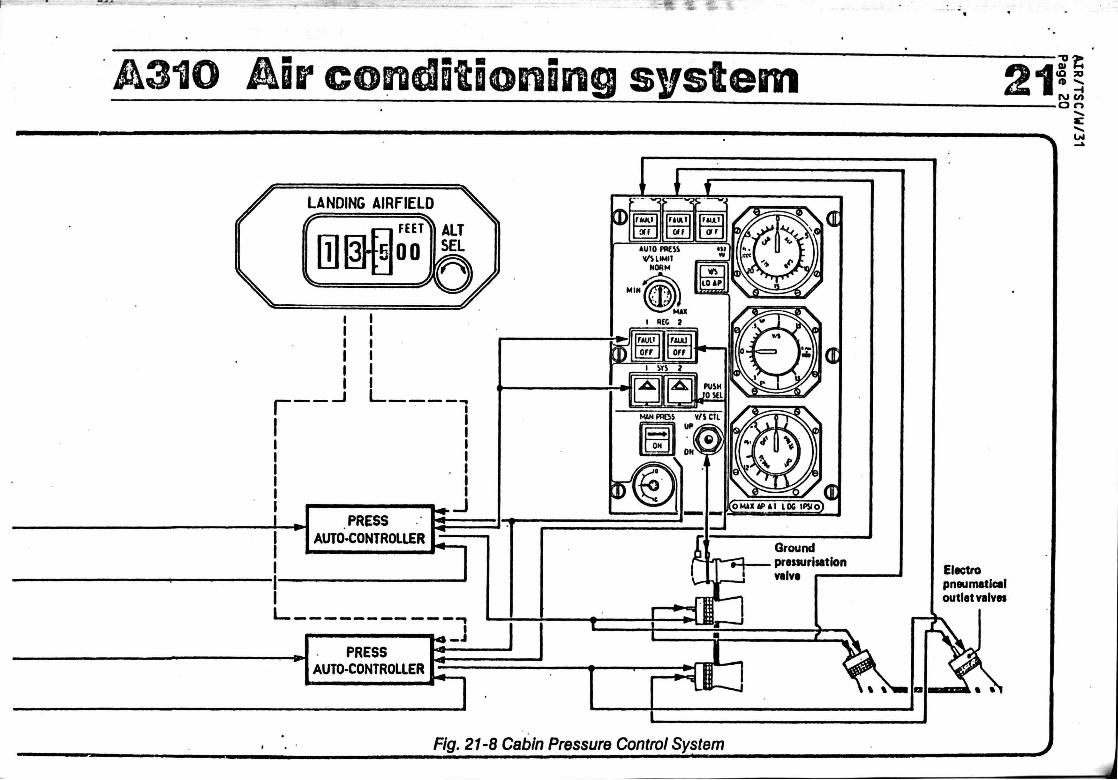
ÂgjQ Mr conjjtjonSBig system 21 6 CABIN PRESSURE CONTROL SYSTEM (See Fig. 21-8)
The A310 Pressure Control System consists of two identical, independent, automatic systems, one being active, the other in stand-by. Switch-over from one to the other is automatic after each flight and in case of failure of the active system. Failure of a system is indicated in the flight deck, as well as an indication of which system is active. Manual selection is possible.
In each system, the pressure is controlled by two electro-pneumatic outlet valves, one situated forward of the air conditioning bay, the other aft of the bulk cargo compartment. The system function is dependent on pre-programmed cabin pressure altitude and rate of change of cabin pressure, aircraft altitude and preselected landing airfield elevation. It is possible to close the electro-pneumatic valves manually by switches on the flight deck. It is also possible to manually control the cabin pressure by means of the ground depressur-isation valve, adjustable by a switch on the overhead panel in the event of failure of both normal systems. Alternatively, a mechanically controlled valve may be used in this situation. This valve 1s situated below the flight deck, with control by means of a wheel on the first
officer's lateral console. Ground depressurisation 1s achieved automatically by electrically opening the pneumatic valves and the ground de-pressurisation valve.
Cabin excess altitude, excess pressure and negative excess pressure are prevented by additional automatic functions of the electro-pneumatic valves.
Automatic prepressurisation of the cabin before take-off is provided to prevent a noticeable pressure fluctuation in the cabin during rotation on take off. To achieve this prepressurisation, outlet valves and the depressurisation valve are closed for approximately 1 minute. Prepressurisation is maintained for 15 seconds after take off, when the cabin pressure control is automatically switched to Its normal inflight mode.
ALTIMETERS
Auto changeover logic (ground/flight failure)
•o >
CAI
Agio Air condjjjonjng system 21? SE
- o r>
1/4
Electro pneumatlcal outlet valve*
Fig. 21-8 Cabin Pressure Control System

A310 Mr CQBidStSoBiBiig system 21 7 CARGO COMPARTMENT
HEATING AND VENTILATION
The bulk cargo compartment of the A310 standard aircraft is heated and ventilated. A similar system can be fitted in the forward cargo compartment as an option.
The air is supplied to the heated cargo compartment through a distribution duct along the left hand side of the compartment. The air is extracted from the cabin, reheated by additional hot air bled from the hot air manifold. The hot air supply 1s controlled by a trim valve, which regulates the cargo compartments temperature. Temperature control of the cargo compartment is achieved in a similar manner to that of the cabin, using inputs from the flight deck preselector, the cargo compartment air temperature sensor, and the air supply duct sensor to control the trim air valve. The air is extracted from the cargo compartment through vents near the ceiling on the right hand side by an electrical fan. The extracted air from the bulk cargo compartment is passed under the compartment floor to provide floor heating. The extracted air from the forward cargo compartment is passed directly aft to the forward outlet valves. Underfloor heating of the forward cargo compartment is provided by extracted air from the electrical and electronic racks.
Temperature sensors
Air in —I
Air out
Fig. 21-9 Cargo Compartment Ventilation
•D > Ql t-t (O 30 n -v.
-» o

AIR/TSC/W/31 Page 22
FICHE DE PROPOSITION 4/82 : N C C 0 : Voir rubrique 2
1 - Désignation du produit -
Equipements de génération et de distribution de l'énergie électrique
de bord, ensembles, sous-ensembles, leurs parties et pièces détachées identi
fiables.
.2 - £lassifacation_tarifaire_-_gositions nouvelles demandées -
NCCD TSUS T. Can.
Transformateur inférieur à ) 1 E V A (
Batteries d'accumulateurs ) électrochimiques.. (
85-01
85-04
Dispositifs d'interruption,) de commutation et de con- ( 85-19 nexion )
câbles (pieuvres & harnais) 85-23
3 - Exemple d'utilisation -
Voir document annexé :
- extrait A T A 100, chapitre 24
4 - Description technique -
La fourniture de l'énergie électrique au sol et en vol à l'ensemble
des systèmes de bord, utilisateurs d'électricité dans un aéronef,est assurée
par des installations :
- de génération électrique
- de distribution électrique.
Ces installations font intervenir de nombreux matériels à vocation
spécifique aéronautique, notamment :
- des générateurs :
. alternateurs avec ou sans ) variateur de vitesse, avec ( ou sans changeur de fré- ) 85-01 (couvert) quence pour le réseau 400 ( Hz. )
. générateurs à courant con- ) tinu assurant ou non le dé-( 85-01 (couvert) marrage de turbo-machines )
b a t t e r i e s d'accumulateurs ) électrochimiques au plomb ou( au nlckel-cadad.ua )
AIR/TSC/U/31 Page 23
85-04 ( non ) (couvert)
des dispositifs de mesure de régulation, de protection, de détection
et de commande :
voltmètres, ampèremètres, fréquencemètres, etc..
boîtiers de régulation de générateurs,
boîtiers de commande et de protection de générateur
) ( ) ( ) ( ) ( ) ( ) (
systèmes de gestion de la distribution électrique (la répartition, le contrôle, la protection)
systèmes de surveillance des) installations électriques ( inhérents à la sécurité des ) vols (délestages automatique^ circuits de secours), détec-) teurs de sous-tension, de .. ( surtension, de sous fré- ) quence, de surfréquence,etc (
90-28 (couvert)
des dispositifs d'interruption et/ou de commutation:
. contacteurs
. contacteurs disjoncteurs
. conjoneteurs disjoncteurs
. commutateurs, interrupteurs /
. relais ) ( )
85-19 ( non ) (couvert)
disjoncteurs
déclencheurs
- des dispositifs de conversion
trans forma teurs
convertisseurs
transformateurs redresseurs
redresseurs
chargeurs de batteries
(
) ( •T ( ) ( ) ( ) ( )
( couvert ) (en partie)
(couvert)
( non ) 85-01 (couvert)
(dans le) ( NCCD )
(couvert) (dans le) ( TSUS )
682-08
682-61
'

AIR/TSC/W/31 Page 24
des dispositifs de connexion
. connecteurs 85-19
. câblages (pieuvres & harnaid 85-23
( non ) (couvert)
(couvert) (dans le) ( NCCD ) (couvert) (partiel) (lement ) (par le ) ( TSUS )
688-14
5 - Importance du besoin -
L'énergie électrique est indispensable au fonctionnement de la
quasi totalité des équipements d'un aéronef, donc au déroulement des vols
dans des conditions de sécurité admissible.
6 - Obstacle, au détournement de destination -
Ces matériels assurent une mission spécifique pour le bon dérou
lement des vols (voir par exemple, document ci-joint relatif aux spécifica
tions techniques d'une installation électrique d'avion), ils sont parfaite
ment identifiables, ils répondent à des exigences particulières, à des nor
mes nationales et/ou internationales et doivent satisfaire à des contrôles
sévères.
Problème de prix.
-
EDITION
ISSUE 28.12.81
AIR/TSC/W/31 Page 25
A1K TRANSPORT ASSOCIATION OF AMERICA
NORMALISATION DE LA DOCUMENTATION TECHNIQUE DES CONSTRUCTEURS
SYST. CHAP.
24
SOUS-SYST/ SECTION
TITRE
GENERATION ELECTRIQUE
-00
-10
-20
Généralités
Entraînement génératrices
Génération alternative
-30 Génération continue
-40
-50
Alimentation extérieure
Distribution
DEFINITION
Equipements et composants électriques qui produisent, commandent et distribuent du courant alternatif et/ou continu à d'autres circuits, y compris génératrices, relais, convertisseurs, batteries, etc., par l'intermédiaire des barres secondaires. Comprend aussi des éléments électriques courants- tels que câblage, commutateurs, prises, etc.
Mécanismes entraînant les génératrices à un régime prévu. Comprend, par exemple, le circuit de graissage, les dispositifs de connexion, les circuits de signalisation/contrôle et d'alarme de 1'entraînement, etc.
Partie des systèmes qui assure la génération, la régulation, la commande et la signalisation/ contrôle de la génération alternative. Comprend, par exemple, les convertisseurs, alternateurs, éléments de commande et de régulation, circuits de signalisation/contrOle, etc., tous les câblage jusqu'aux barres principales non comprises.
Partie des systèmes qui assure la génération, la régulation, la commande et la signalisation/ contrôle de la génération continue. Comprend, par exemple, les génératrices et alternateurs, transformateurs, redresseurs, batteries, éléments de commande et de régulation, circuits de signalisation/contrôle, etc., tous les câblages jusqu'aux barres principales non comprises.
Partie du système à l'intérieur de l'aéronef reliant l'alimentation électrique extérieure au circuit électrique de l'aéronef. Comprend, par exemple, les prises, relais, commutateurs, câblages, alarmes lumineuses, etc.
Partie des systèmes permettant le branchement des sources de courant alternatif ou continu aux circuits d'utilisation. Comprend, par exemple, les barres principales et secondaires alternatives et continues, disjoncteurs des circuits principaux, dispositifs du circuit d'alimentation, etc.
$31© Elect Heal power :4 0» M (Q »
CONTENTS
1 GENERAL 2 NORMAL FLIGHT
CONFIGURATION 3 ABNORMAL FLIGHT
CONFIGURATION 4 AIRCRAFT GROUND SUPPLY 5 ELECTRICAL POWER
GENERATION CONTROLS
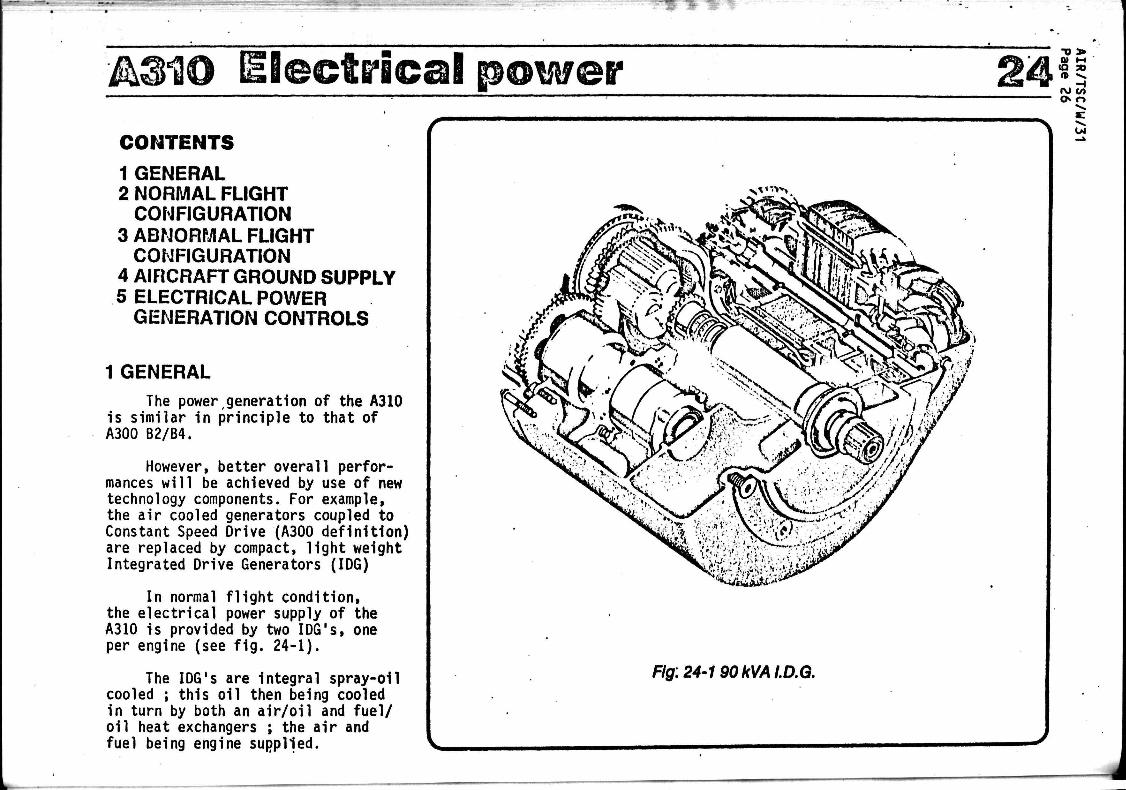
1 GENERAL The power,generation of the A310
is similar in principle to that of A300 B2/B4.
However, better overall performances will be achieved by use of new technology components. For example, the air cooled generators coupled to Constant Speed Drive (A300 definition) are replaced by compact, light weight Integrated Drive Generators (IDG)
In normal flight condition, the electrical power supply of the A310 is provided by two IDG's, one per engine (see fig. 24-1).
The IDG's are integral spray-o1l cooled ; this oil then being cooled in turn by both an air/oil and fuel/ oil heat exchangers ; the air and fuel being engine supplied.
N * '">'*».
*M&S&*t*
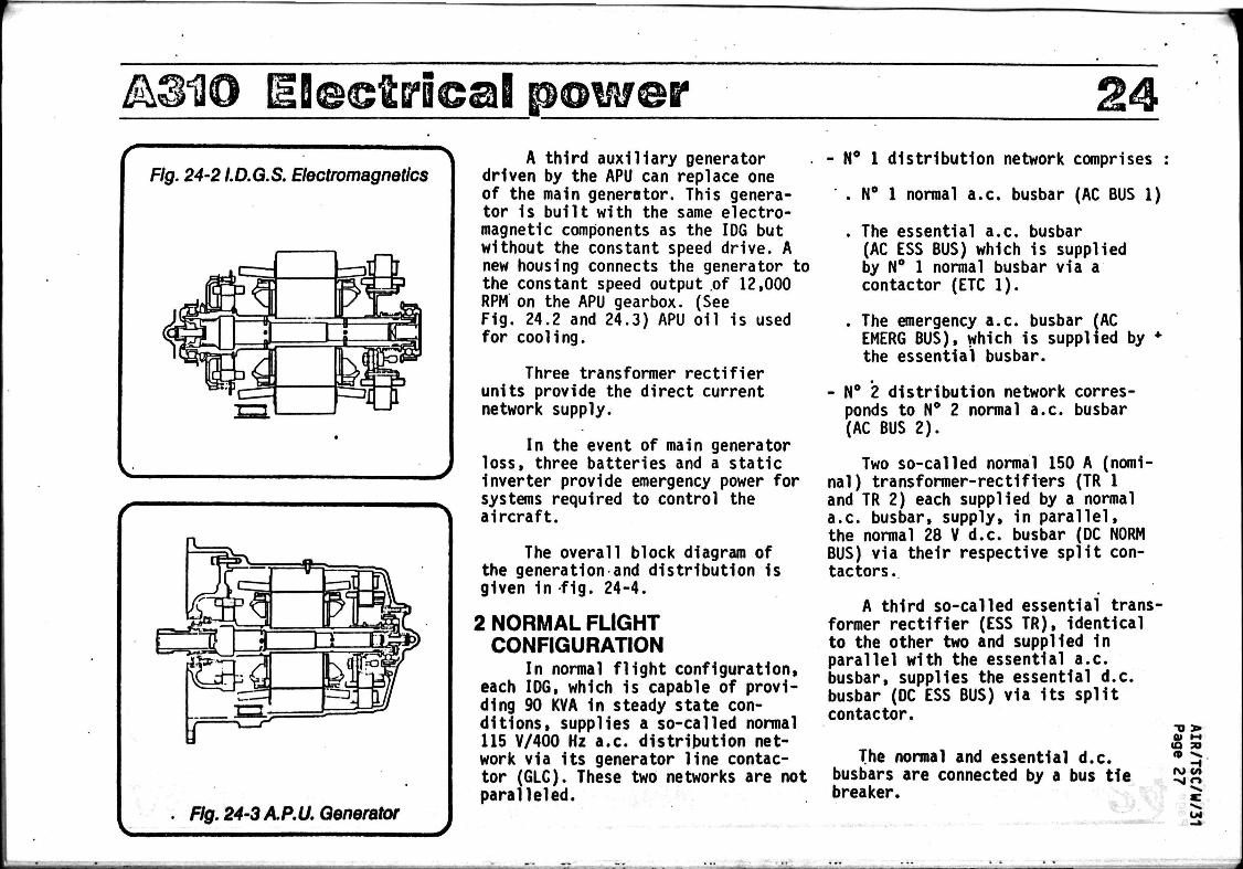
Flg:24'190kVAI.D.Q.
A@1@ Ejeejgjcaj power 24 A third auxiliary generator
driven by the APU can replace one of the main generator. This generator is built with the same electromagnetic components as the IDG but without the constant speed drive. A new housing connects the generator to the constant speed output of 12,000 RPM on the APU gearbox. (See F1g. 24.2 and 24.3) APU oil is used for cooling.
Three transformer rectifier units provide the direct current network supply.
In the event of main generator loss, three batteries and a static inverter provide emergency power for systems required to control the aircraft.
The overall block diagram of the generation and distribution is given 1n fig. 24-4.
2 NORMAL FLIGHT CONFIGURATION
In normal flight configuration, each IDG, which is capable of providing 90 KVA 1n steady state conditions, supplies a so-called normal 115 V/400 Hz a.c. distribution network via its generator line contactor (GLC). These two networks are not paralleled.
- N° 1 distribution network comprises :
. N° 1 normal a.c. busbar (AC BUS 1)
. The essential a.c. busbar (AC ESS BUS) which is supplied by N° 1 normal busbar via a contactor (ETC 1).
. The emergency a.c. busbar (AC EMERG BUS), which is supplied by * the essential busbar.
- N° 2 distribution network corresponds to N° 2 normal a.c. busbar (AC BUS 2).
Two so-called normal 150 A (nominal) transformer-rectifiers (TR 1 and TR 2) each supplied by a normal a.c. busbar, supply, in parallel, the normal 28 V d.c. busbar (DC NORM BUS) via their respective split contactors.
A third so-called essential transformer rectifier (ESS TR), identical to the other two and supplied In parallel with the essential a.c. busbar, supplies the essential d.c. busbar (DC ESS BUS) via its split contactor.
The normal and essential d.c. busbars are connected by a bus tie breaker.
.
TJ 3» 01 1-4 (Q TO «P « V
-I ru </>
5:
2&3H0 Electr ical p@wer !4 -o > Q> M
H i v c/> oo r>
DC NORM BUS
I I BUS TIE [ 8 A T ÏE BATCC B A T Ï L
-TT -q Tj
r r £* T
DC ESS BUS
i l uuDu mm TRI
UJUJ
ESSTR
ETC1
AC BUS 1
GLC1
j A A A-,
BTC1
GLC3
I 1
]
INV
I
TR2
I AC ESS BUS
IDG1
ETC 2 A
pvi AC EMERG BUS
ÏL AC BUS2
EPC^
BTC2 - A A_
a ETC 3
A _
AI r\ l GEN J | ( QEN 1
GLC2 l\
I rëiôl l_! IJMOT I
APU
A EXT PWR
IDG 2
I, I !©! • I CSO i
M0T2L' L-i
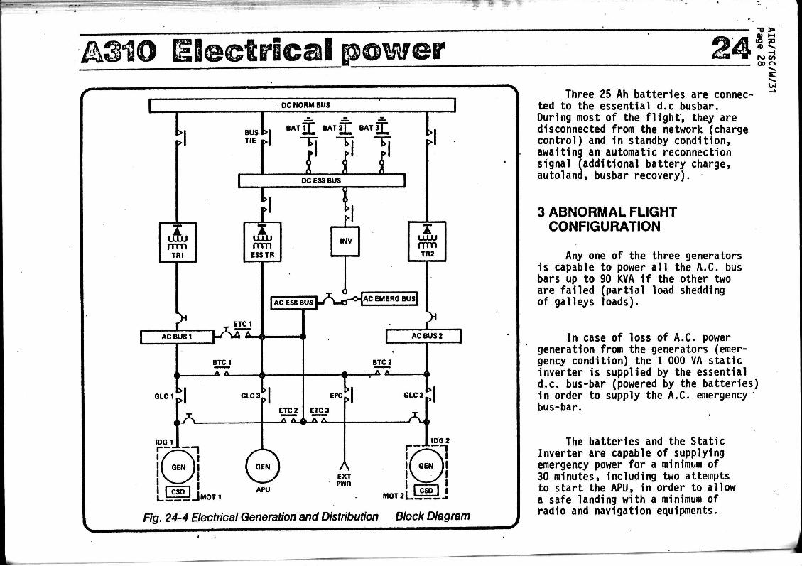
Fig. 24-4 Electrical Generation and Distribution Block Diagram
Three 25 Ah batteries are connected to the essential d.c busbar. During most of the f l i g h t , they are disconnected from the network (charge control) and in standby condition, awaiting an automatic reconnection signal (additional battery charge, autoland, busbar recovery).
3 ABNORMAL FLIGHT CONFIGURATION
Any one of the three generators is capable to power all the A.C. bus bars up to 90 KVA if the other two are failed (partial load shedding of galleys loads).
In case of loss of A.C. power generation from the generators (emergency condition) the 1 000 VA static inverter is supplied by the essential d.c. bus-bar (powered by the batteries) in order to supply the A.C. emergency bus-bar.
The batteries and the Static Inverter are capable of supplying emergency power for a minimum of 30 minutes, including two attempts to start the APU, in order to allow a safe landing with a minimum of radio and navigation equipments.
Oi

A310 pow©? 24 4 AIRCRAFT GROUND SUPPLY
On the ground, the entire aircraft network can be supplied via the two bus transfer contactors (BTC 1 and BTC 2) :
- either from the auxiliary generator (APU GEN) via its Une contactor (GLC 3) ;
- or from the ground power unit (EXT PWR) via the ground power contactor (EPC).
When both these sources are available simultaneously, the ground power unit has priority for supplying the aircraft.
It should be noted that:
- for ground servicing operations, it is possible to supply only part of the normal a.c. and d.c. networks.
- it is also possible to perform refuelling operations without a ground power unit by using one of the aircraft batteries and the static inverter as a source of electrical power.
5 ELECTRICAL POWER GENERATION CONTROLS
The electrical power generation and distribution control, indication and monitoring equipment is located on the flight deck overhead panel: (See fig. 24-5).
a) Main Panel (See Fig. 24-6)
This panel represents the general layout of the system and groups together the main controls and indications, and Shows each of its components in detail ;
Fig. 24-7
Fig. 24-6
Fig. 24-5 Electrical Power Generation and Distribution Control
-o > (O TO
n -^ -t
rv» c/i
04

A310 EI@©tric@B pewer & & & » %
m ON
AC ESS ON INV
eviii CN
KU.I
OFF/R
IOC 2
rami (DISC J
i 4
• o
— Smoke detection warning in the cooling system of corresponding racks
— Effective load shedding indication — Guarded control for setting into "Minimum Equipment" configuration in "Smoke emergency"
procedure
— Control for setting into " t a v Land" configuration in "Smoke emergency" procedure
— Control for setting into operation of battery/charge monitoring unit and indication of battery contactor position
— Thermal runaway warning for any of the three batteries
— Control for connecting the three batteries (charge monitoring unit overriding)
— Smoke detection warning in battery ventilation system — Warning for D.C. essential bus bar powered by battery only
— Warning for D.C. normal bus bar loss
— Indication of A.C emergency bus bar powered by static inverter
— Warning for A.C essential bus bar toss
— Guarded control for essential bus bar and TR power transfer and indication of contactor . position
— Warning for A.C normal bus bar loss
— Indication of external power availability — Control and indication of external power utilization
— A.C generator failure warning — Control for exciting and connecting A.C generator
— Overload warning for any of the three A.C generators — Control and indication of galley load shedding
— Guarded control for EOG disconnection — IDG overheat warning — IDG oil pressure drop warning
Fig. 24-6 Electrical Power Panel
04 C/> O O
UJ

A31Û Ele©tri<ea! p@wer !4
b) Monitoring Panel (See fig. 24-7)
An adjacent panel accommodates the monitoring instruments :
- A.C. : voltmeter, frequencymeter and load indicator associated with a rotary switch for selecting the source of the information presented (generation, distribution busbars).
NB : A rotary switch is provided on the maintenance panel for selecting the voltage phase to be indicated.
- P.C. : voltmeter and ammeter associated with a rotary switch for selecting the source of information to be displayed (generation or distribution busbar).
BUS'E S S EMER , C E N
I A.C. INDICATIONS SELECTOR
Frequencymeter
dx. ammeter
B
Fig. 24-7 Monitoring Panel
dx. voltmeter
j - * dx . indications selector
-o > 01 HI IO » n **
-t
u i

AIR/TSC/W/31 Page 32
FICHE DE PROPOSITION 5/82 NCCD: Vo i r rubr ique 2
1 - Désignation du produit -
Equipements de protection contre l ' incendie (Fire protection) à bord de
aéronefs c i v i l s , ensembles, sous-ensembles, pa r t i es , pièces détachées 'spécifi
ques.
2 - C la s se^n t_ t a r i f a i r e^_£os i t i ons_nouy^ le s^ -
T.Cn
) ( )
(
NCCD
(1) 84-21
- (2) 84-61
85-19
TSUS
cartouches pour extincteurs
vannes de décharge
clapets anti-retour
sélecteurs de bouteilles d'extinction
poignées d'extinction 85-19
3 - Eacemgle^d^utilisation. -
Tout avion de transport civil doit obligatoirement.posséder des systèmes
de détection d'incendie et des systèmes d'extinction. Ceux-ci sont complétés par
des systèmes de détection de fumée (cabine, soute).
4. - Description technique -
Il y a complète indépendance entre systèmes de détection et d'extinction
L'extinction est commandée par le personnel navigant, afin d'éviter un déclenche
ment intempestif des extincteurs.
a) Systèmes de détection :.
- détecteurs ponctuels ) ou linéaires ( 85"17 (couvert)
- boîtiers de détection) nn no , ^ et de test ( 90"28 < c o w e « >
- alarmes visuelles et/) (couvert) ou sonores ( (détecteurs d'échauf- ) fement, de fumée) (
b) systèmes d'extinction (zones : moteur, AFU et soutes)
- poignées de commande , 85-19 , ^N r 6 ( (couvert)
(1) Voir Fiche 1/C2 (2) Voir Fiche 2/82

- sélecteurs de boutéil-) les d'extinction ( 85-19 ( non )
- extincteurs - cartouches
teurs.
- vannes de'décharge
(couvert)
84-21 (couvert)
( non )
AIR/TSC/W/31 Page 33
662-52 (couvert) pour extinc-) , 0 - , (
( (couvert) ) ( non ) '. 84r61 ) """ ' ( (couvert)
c) systèmes d 'extinct ion portatifs(zone cabine) ou automatiques ( to i l e t t e s ) .
- ext incteurs 84-21 (couvert) 662-52 (couvert)
- boute i l les d'oxygène ) » - , « « / *.\ •»«« , e i \ e t masques ( 9 0 ~ 1 8 < c o w e r t > 709-46 (couvert)
5 - Importance du besoin -
Ces systèmes sont indispensables à la sécuri té des vols.
6 - Obstacle au détournement de destination -
. Spécifici té technique
. Sources spécial isées
. Prix élevés
Les matériels u t i l i s é s (y compris les extincteurs)sont spéci f iquesr environnement pa r t i cu l i e r ^ nature des f lu ides u t i l i sés- , construction légère, normes, e t c . ~ -
7 - Observations -
Extincteurs mis. à par t , les équipements de ces systèmes ne sont pas cou
verts par l'Accord. I l s représentent une part non négligeable du coût des i n s t a l
lations de bord de protection contre l ' incendie et de leur entret ien.
EDITION ISSUE 22.1.82 15. 2.82

AIR/TSC/W/31 Page 34 AIR TRANSPORT ASSOCIATION OF AMERICA
SPECIFICATION DE LA DOCUMENTATION TECHNIQUE DES FABRICANTS
(6) SYST/ SOUS-SYST/ (25) CHAP. SECTION
26
(16)
-00
-10
-20
-30
TITRE
PROTECTION CONTRE L'INCENDIE
Généralités
Détection
Extinction
Protection contre l'explosion
DEFINITION
Equipements et composants fixes et portatifs qui détectent et signalent la présence g'un incendie ou de fumée, et emmagasinent ou dis tribuent le produit d'extinction dans toutes les zones protégées de l'aéronef. Comprend les bouteilles, clapets, canalisations, etc.
Partie du système servant à détecter et à signaler la présence d'une surchauffe, de fumée ou d'un incendie.
Parties fixes ou portatives du système servant à éteindre l'incendie.
Partie du système servant à détecter, à Signaler et à éteindre les flammes qui se propagent dans la mise à 1' air libre ou les bouches de ventilation du circuit carburant, afin de prévenir l'explosion de ce circuit.
AIR/TSC/W/31 Page 35
26-00.00.00 FIRE PROTECTION
26-IO.OO.OO FIRE DETECTION - MAIN ENOINES
•01.00 A continuous element dual loop type f i r e detect ion system RFC 6-1! w i l l be provided for each engine.
.02.00 The systems wi l l be independent with maximum emphasis on RFC 6-1! r e l i a b i l i t y and freedom from fa l se alarms due t o a short or open c i r c u i t , t o allow dispatc l iab i l i ty with one c i r c u i t inopera t ive .
•03.00 Tne system w i l l allow a crew member t o check the elements RFC 6-1 : for cont inui ty and ident i fy an inoperat ive c i r c u i t in f l i g h t .
• Ob.00 Fire detector elements and connectors w i l l be secured and RFC 6-12 | routed so t ha t :
.OU.01 The element has positive protect ion from damage during RFC 6-12 maintenance including cowling operation and engine component replacement ;
«OU.02 Elements with different alarm se t points w i l l be a t l e a s t RFC 6-12 6 inches d i f ferent in length . Elements with the same alarm set point w i l l be e i t h e r the same length or a t -l eas t 6 inches different in length ;
.01*.03 Clearance between .the element and adjacent s t ruc ture w i l l RFC 6-13; be maintained ;
•OU.OU Fi re detect ion elements w i l l be e a s i l y replaceable ; RFC 6-13
.OU.05 Element connections w i l l be moisture proof. RFC 6-13
• 05*00 When operated normally as a dual system, a short t o ground RFC 6-lU or open in one loop c i r c u i t w i l l not i n i t i a t e a f a l se f i r e alarm.
.06.00 An engine f i r e warning w i l l be indicated by :
.06,01 i l luminat ion of a red l i r t i t on the cen t ra l warning panel
.06.02 i l lumination of a red l i gh t in the respect ive f i r e control and f i r e extinguishe'r lever
.06.03 a f i r e b e l l
.07.00 Activation of the fire control lever will turn off and reset the fire bell.
.07.01 A fire bell audio cancel push button will be provided RFC 2J.91* behind the fire control lever.
A.300 B/ATLAS

AIR/TSC/W/31 Page 36
26-11.00.00 FIRE DETECTION - APU
.01.00 A dual continuous f i r e detect ion system w i l l be i n s t a l l e d for the pro tec t ion of the APU and i t s equipment.
•02.00 The number of components in the detect ion systems w i l l be kept t o a minimum and i t w i l l be poss ible t o replace them v i thou t removing the APU.
• 03*00 The f i r e de tec t ion systems v i l l be of t he same type as t h a t used for the main engines and v i l l be ins t a l l ed in the APU compartment.
•04.00 A f i r e warning w i l l be indicated by :
• OU.01 A l i g h t on the f l igh t deck APU panel
.04.02 A warning b e l l
.04.03 An e l e c t r i c horn which w i l l operate when the a i r c r a f t i s on the ground, t o provide a warning t o t he ground crew.
26-12.00.00 SMOKE DETECTION
•01.00 A smoke de tec t ion system w i l l be provided for the f o l l o wing compartments :
•01.01 Front equipment-compartment
•01*02 - Front f r e igh t compartment •01.03 Centre f re igh t compartment •01.04 Rear f re ight compartment RFC 5-42 SI •01*05 Outlet of t he b a t t e r i e s v e n t i l a t i o n duct RFC 5=51 •02.00 Red warning l i g h t s ind ica t ing the source of smoke w i l l be
provided in the f l i gh t deck. •02.01 A smoke warning in the c e n t r a l warning panel w i l l repeat RFC 2-57
a l l smoke warnings. •02.02 Automatic shut down of the SMOKE red l i g h t s when the smoke RFC 2-69
disappears w i l l be provided. 26-20.00.00 FIRE EXTINGUISHING - MAIN ENGINES
.01.00 Fire ext inguishing w i l l be provided for the accessory zone in the fan cowling and t h e forward zone around the gas generator , in the form of a two-shot system, each shot being supplied by a single-head b o t t l e .
•01.01 There w i l l be two b o t t l e s for each pod connected to a s ing le d i s t r i b u t i o n system.
A. 300 B 2/ATLAS
AIR/TSC/W/31 Page 37
26-20.02.00 Connections in the fire extinguishing system, subject RFC 6-142 to relative notion between components, will be made of flexible and fire-resistant materials.
.03.00 Magnetic indicators will be provided on the flight deck to give indication of extinguisher bottle discharge.
26-21.00.00 FIRE EXTINGUISHING - AFP
.01.00 The fire extinguishing system will comprise a Freon bottle and necessary plumbing to discharge into the APU compartment.
.02.00 In the event of a fire warning an automatic system will shut down the APU and, after a delay of 5-10 seconds, will operate the fire extinguisher.
.02.01 This automatic system will operate on the ground only, manual operation being required under normal flight conditions.
26-22.00.00 FIRE EXTINGUISHING - FRONT FREIGHT COMPARTMENT
.01.00 A one shot fire extinguishing system for the front or centre freight compartment will be provided.
A.300 B2/ATLAS

w m *
A310 IFi^e pro tec t ion •o >
01 M
00 o
CONTENTS
1 INTRODUCTION 2 FIRE PROTECTION FOR
ENGINES AND APU 3 FIRE PROTECTION FOR
ELECTRONIC BAY 4 FIRE PROTECTION FOR CARGO
COMPARTMENTS
1 INTRODUCTION Aircraft fire protection systems
are provided for :
engines and APU comprising fire detection and extinguishing system ;
electronic bay with a smoke detection system ;
cargo compartments comprising a smoke detection and fire extinguishing system.
2 FIRE PROTECTION FOR ENGINES AND APU
. The fire detection systems for the engines and the APU are from SYSTRON-DONNER. The detection loops are of
pneumatic type. (See fig. 26<-l). Basically, they consist of a stainless steel tube (1,6 mm diameter) filled with helium. The helium is prepressu-.rized (2-3 bar).One end of the tube is equipped with two pressure switches, one of them detecting continuously the prepressure (fault switch), the other one providing an alarm signal as soon as the helium pressure rises above a preset value due to overheat. In order to achieve a sufficient Increase of gas pressure even with a discrete fire, a metal hybrid core element 1s provided inside the tube. This metal hybride releases a significant amount of hydrogen when being heated, thus
Alarm switch
Power i
Signal
Electrical isolator/pneumatic manifold
Core element Metal hybride
Sensor tube
Fault switch
Fig. 26-1 Engine or A.P.U. Fire Detection (principle)

&310 Fire APU panel Engine 2 panel
Extinguisher bottles
Engine core fire detector
Fig. 26-2 Engine Fire Protection System
-o > (O TO « «̂
- I W CO
04

A310 Fore protection 26 operating the alarm switch in case of a local fire.
. All the detector loops are duplicated (loop A and B). In a control box (one per engine and APU), the alarm signals of the two loops are AND - gated in order to avoid false warnings. On the respective fire protection panel (one for each engine and for the APU,'located on the overhead panel), the fire alarm signal illuminates the indicator in the fire handle, both Loop-lamps, and activates the flight warning system (See fig. 26-2).
The fault signal and the alarm signal of each loop are OR - gated in order to indicate a loop failure by the respective LOOP light.
. In each nacelle, one duplicated detector loop is located in the lower part of the pylon and a second one on the engine core (GE engines having a third one on the fan). The APU compartment is equipped with one duplicated loop. The alarm temperatures are different for the various locations ; they are preset via the prepressure in the detectors.
. The fire extinguishing system for each nacelle consists of two extinguisher bottles (APU : one bottle), installed in the rear part of the
pylon and filled with Halon 1301. The two bottles are connected via a tube to the spray nozzles, the locations of which depending on the type of engine. Each bottle can be discharged by means of a double wired cartridge. The continuity of the doubled wiring can be tested by pushing the Squib test button on the fire protection panel. The light SQUIB comes on when both wires are intact (while one of them being sufficient to fire the cartridge).
. In case of engine fire, the extinguishing procedure is as follows :
- throttle to idle
- shut high pressure fuel cock (which is lighted due to the fire alarm)
- pull fire handle (which shuts hydraulic suction lines, fuel LP valve, appropriate bleed air valve, and which opens the generator field circuit)
- wait 10 seconds (slow down of engine)
- push the button AGENT 1 to discharge one of the extinguisher bottles (only possible after the fire handle has been pulled)
- if alarm persists, push the
button AGENT 2.
In case of APU fire, the APU will be shut down automatically or will have to be shut down manually depending where the fire is detected.,
The extinguishing procedure is then similar to the procedure used for engine (only one AGENT).
3 FIRE PROTECTION FOR ELECTRONIC BAY Smoke in the electronic bay is
detected by four smoke detectors which are of the ionisation type. They detect smoke 1n the cooling air extraction ducts of the different groups of equipment, as shown in fig. 26-3.
The signals are elaborated in the detector box (the same as used for cargo compartments) and the respective smoke warning light on the overhead panel comes on.
The presence of smoke in the smoke emergency shelf and in two of the three inertial reference systems can be confirmed by a sniffer which Is provided with a small fan.
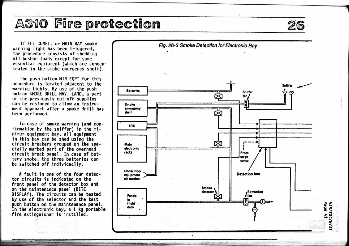
AM® (Fire prot©©ti®ei If FLT COMPT. or MAIN BAY smoke
warning light has been triggered, the procedure consists of shedding all busbar loads except for some essential equipment (which are concentrated in the smoke emergency shelf).
The push button MIN EQPT for this procedure is located adjacent to the warning lights. By use of the push button SMOKE DRILL NAV. LAND, a part of the previously cut-off supplies can be restored to allow an instrument approach after a smoke drill has been performed.
In case of smoke warning (and confirmation by the sniffer) in the minimum equipment bay, all equipment in this bay can be shed using the circuit breakers grouped on the specially marked part of the overhead circuit break panel. In case of battery smoke, the three batteries can be switched off individually.
A fault in one of the four detector circuits is indicated on the front panel of the detector box and on the maintenance panel (BITE DISPLAY). The circuits can be tested by use of the selector and the test push button on the maintenance panel. In the electronic bay, a 1 kg portable fire extinguisher is installed.
Fig. 26-3 Smoke Detection for Electronic Bay
Batteries
Smoke emergency shelf
1RS
Main electronic recks
Under floor equipment eir suction
Smoke detector
(Q 50
?3 OJ
£kM® Fire pro1
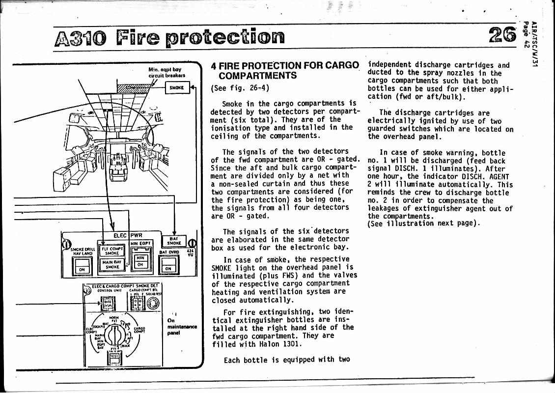
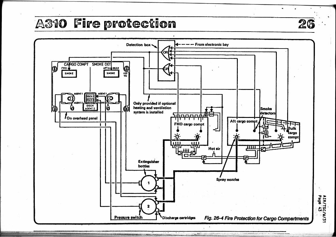
4 FIRE PROTECTION FOR CARGO COMPARTMENTS
(See fig. 26-4)
Smoke in the cargo compartments is detected by two detectors per compartment (six total). They are of the ionisation type and installed in the ceiling of the compartments.
The signals of the two detectors of the fwd compartment are OR - gated. Since the aft and bulk cargo compartment are divided only by a net with a non-sealed curtain and thus these two compartments are considered (for the fire protection) as being one, the signals from all four detectors are OR - gated.
The signals of the six detectors are elaborated in the same detector box as used for the electronic bay.
In case of smbke, the respective SMOKE light on the overhead panel is illuminated (plus FWS) and the valves of the respective cargo compartment heating and ventilation system are closed automatically.
For fire extinguishing, two identical extinguisher bottles are installed at the right hand side of the fwd cargo compartment. They are filled with Halon 1301.
Each bottle is equipped with two
independent discharge cartridges and ducted to the spray nozzles 1n the cargo compartments such that both bottles can be used for either application (fwd or aft/bulk).
The discharge cartridges are electrically ignited by use of two guarded switches which are located on the overhead panel.
In case of smoke warning, bottle no. 1 will be discharged (feed back signal DISCH. 1 illuminates). After one hour, the indicator DISCH. AGENT 2 will Illuminate automatically. This reminds the crew to discharge bottle no. 2 in order to compensate the leakages of extinguisher agent out of the compartments. (See illustration next page).
A®HO Fire pro tec t ion Detection box
COMPT SMOKE DET Anai reuiK A m i rBUlK UfU
ISMOKE I «11
AGENT I
AGENTS
On overhead panel
I I
V V — From electronic bay
« f t
T Only provided if optional heating and ventilation system is installed _-
Extinguisher bottles
ippppf. yap2*-] FWD cargo compt
I 1 _ & *
•MM—MM—
^3CI Hot air
té
Smoke detectors
Aft cargo come
Pressura switch
Spray nozzles
-D > 01 t-t
* * CO CMr>
Discharge cartridges Fig. 26-4 Fire Protection for Cargo Compartments J à

AIR/TSC/W/31 Page 44
FICHE DE PROPOSITION' 6/82 NCCD: voir rubrique n° 2
1 - Désignation du produit -
Equipements pour le chargement et le déchargement (automatique ou non)
du fret à bord d'avion, ensembles, sous-ensembles, leurs parties et pièces déta
chées Identifiables.
^ " £1*2£Îfi£2tion__tarifaire_-_gositions_^nouvelles demandées -
HCCD TSUS T.Cn
Rouleaux à billes l _, ..
Rouleaux à billes motorisés )
Moteurrréducteur d'entraînement) /w
j . .r j i TTT* / 85-01 682-42
de moins de 1 HP ( Dispositifs de blocage 84-22 664-12
Dispositifs de détection lumi- ) aç_ 2 1/ Q O_ 2 a 7i?-nfi neuse, de commande d'avancement ( 35-21/90-28 712-06 et de verrouillage )
Bottiers de commande 85-19
3 . Exemgle_d^utilisation -
Le système décrit ici est celui de la version standard des avions gros
porteurs tels : B-747, DC 10 - Lockheed 1011 - B-707 - Airbus A-300 et A-310,
Les avions gros porteurs disposent d'importantes soutes pour le transport de marchandises.
Certains avions civils sont conçus pour le transport exclusif ou partiel
de fret : avions cargos, avions convertibles (quick change), avions mixtes.
Four permettre une mise en place rapide, le fret est conditionné en
containers ou sur palettes normalisés.
Par suite de leur exiguité, il est nécessaire d'équiper les soutes de
dispositifs :
a) Facilitant le déplacement des charges :
- plancher à billes 88-03 (couvert)
- billes avec- réceptacle 84-22 (couvert)
- plancher de roulement à ) ao _, / .% *^ . _ , 88-03 (couvert) rouleaux (
- rouleaux à billes 84-22 , \ (couvert)

FICHE DE PROPOSITION 6/82
b) Permettant leur immobilisation :
- Verrlns de verrouil lage 84-22 (couvert)
- Dispositifs de blocage 84-22 ?
AIR/TSC/W/31 Page 45
664-12 (couvert)
664-12 î
Le temps imparti aux opérations de déchargement et de chargement en
escale étant très court, il est nécessaire de les automatiser. Ce qui conduit
à utiliser, en plus des précédents dispositifs :
a) un système de commande centra-) 9 Q - 2 8 ( c o u y e r t )
lise (
b) un système d'entraînement des conteneurs
- verrins de chargement
- rouleaux motorisés
- moteur-réducteur d'entraînement
c) un système de contrôle :
- dispositif de détection lumineuse (émetteurs, récepteurs)
84-22
) ( ) (
84-22
85-01
) ( )
)
85-21
- "boîtiers de commande (pour la mise en route des( rouleaux motorisés impli-) qués et l'effacement des ( verrous, à mesure que le ) 85-19 container progresse vers ( l'emplacement qui lui est) affecté: Il assure le ver( rouillage du container en) fin de parcours) (
(couvert)
( non ) (couvert) (parties)
( non ) (couvert) ( -moins •) (de 1 HP)
( non ) (couvert)
( non ) (couvert)
664-12 (couvert)
682-42
( non ) (couvert) (.moins ) (de 1 HP)
5 - Lanortance du besoin -
On assiste à la généralisation de ce type d'aménagement sur les avions,
moyens et gros porteurs avec le développement mondial du fret aérien.
La valeur des matériels entrant dans un tel système n'est pas négligeable
elle dépend de l'importance des soutes aménagées et de leur degré d'automaticité.
6 - Obstacles au détournement de destination -
Spécificités techniques :
Ce matériel se distingue des autres équipements de manutention par sa
conception ultra-légère nécessitée par .le fait que le dispositif de chargement
reste à demeure sur avion. Il obéit, par ailleurs aux règlements très strictes
en usage dans l'aéronautique pour la sécurité.
AIR/TSC/W/31 Page 46
FICHE DE PROPOSITION 6/82
Sources s p é c i a l i s é e s :
Comme conséquence de ce t te spéc i f ic i t é , i l y a peu de fournisseurs
sonde capables d 'o f f r i r ce matériel ( t r o i s à quatre) .
Prix élevés
7 - 0DS££ïfHî22f ~
Les Accords aéronautiques du GATT prévoient une exonération des "machines
et appareils de chargement et de déchargement (84-22 - 664-12) à l'exclusion de ii
leurs parties et pièces détachées. Il est souhaitable de savoir quels sont les
matériels qui entrent effectivement dans ces positions et d'assurer une parfaite
réciprocité.
1 !
^
J;
r/
.J**"
:!*£
Mfcri,-
fci 4
7/ ji^aa
AIR/TSC/W/31 Page 47
tfcva. ~-
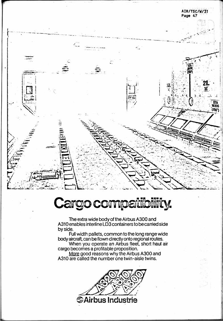
Cargo compatibility. The extra wide body of the Airbus A300 and
A310 enables interline LD3 containers to be carried side by side.
Full width pallets, common to the long range wide body aircraft, can be flown directly onto regional routes.
When you operate an Airbus fleet, short haul air cargo becomes a profitable proposition.
More good reasons why the Airbus A300 and A310 are called the number one twin-aisle twins.
©Airbus Industrie
A3H0 EgpgpBiient/FyrnBsiiing .3 CARGO COMPARTMENTS
a) General
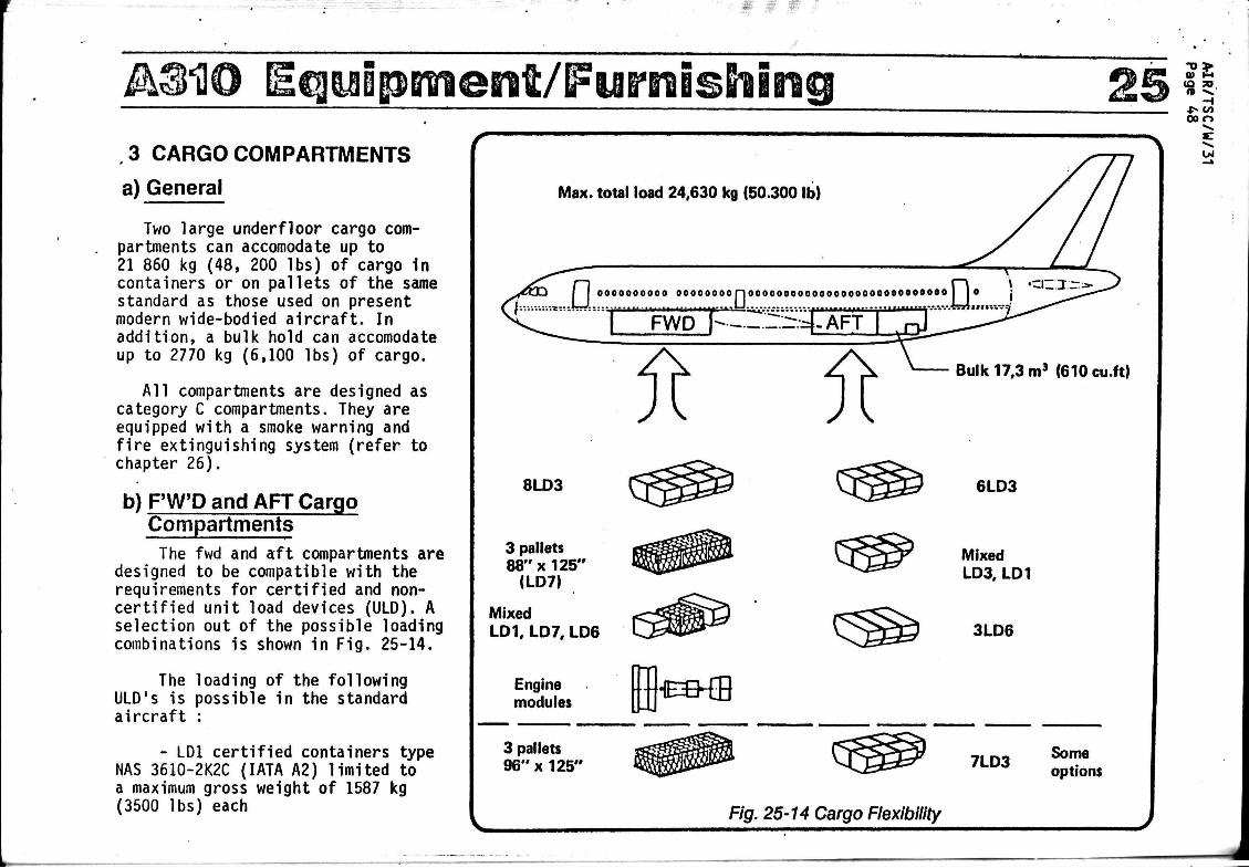
Two large underfloor cargo compartments can accomodate up to 21 860 kg (48, 200 lbs) of cargo in containers or on pallets of the same standard as those used on present modern wide-bodied aircraft. In addition, a bulk hold can accomodate up to 2770 kg (6,100 lbs) of cargo.
All compartments are designed as category C compartments. They are equipped with a smoke warning and fire extinguishing system (refer to chapter 26).
bjF'W'D and AFT Cargo Compartments The fwd and aft compartments are
designed to be compatible with the requirements for certified and non-certified unit load devices (ULD). A selection out of the possible loading combinations is shown in Fig. 25-14.
The loading of the following ULD's is possible in the standard aircraft :
- LD1 certified containers type NAS 3610-2K2C (IATA A2) limited to a maximum gross weight of 1587 kg (3500 lbs) each
n ^ -<
«-> CO 00 o
Max. total load 24,630 kg (50.300 lb)
U l
n f~\ » 'an: : f [ oooooooooo oooooooon00000000O0000000000000OO0O0O I 10 j
I FWD P----.4-AFT '
Bulk 17.3 m3 (610 cu.ft)
8LD3
3 pallets 88"x125"
(LD7)
Mixed LD1, LD7, LD6
Engine modules
6LD3
Mixed LD3, LD1
3LD6
€&ffl
3 pallets 96" x 125' 7LD3
Some options
Fig. 25-14 Cargo Flexibility
AQUO Ecpip - LD3 certified containers type
NAS 3610-2K2C (IATA Al) limited to a maximum gross weight of 1587 kg (3500 lbs) each.
- LD5 certified full size containers type NAS 3610-2L2C limited to a maximum gross weight of 3175 kg (7000 lbs) each.
- LD7 pallets (88" x 125") type NAS 3610 2A1P, 2A2P, 2A3P, 2A4P, and 2A6P limited to a maximum gross weight of 4627 kg (10 200 lbs).
Provided that the requirements of the Weight and Balance Manual are met, all non-certified half and full size containers as defined above can be loaded to the maximum gross weight equivalent to 2K1C/2L1C (2830/5660 lbs).
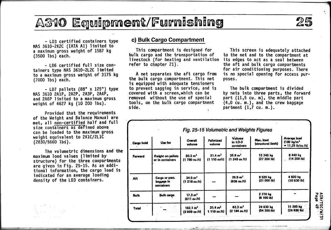
The volumetric dimensions and the maximum load values (limited by structure) for the three compartments are given in Fig. 25-15. As an additional information, the cargo load is indicated for an average loading density of the LD3 containers.
Bratt/FytrroBshimg c) Bulk Cargo Compartment
This compartment is designed for bulk cargo and the transportation of livestock (for heating and ventilation refer to chapter 21).
A net separates the aft cargo from the bulk cargo compartment. This net is equipped with adequate tensioners to prevent sagging in service, and is covered with a screen,which can be removed without the use of special tools, on the bulk cargo compartment side.
This screen is adequately attached to the net and to the compartment at its edges to act as a seal between the aft and bulk cargo compartments for air conditioning purposes. There is no special opening for access purposes.
The bulk compartment is divided by nets into three parts, the forward part (11,5 eu. m ) , the middle part (4,0 eu. m . ) , and the crew baggage partment (1,7 eu. m.).
Cargo hold
Forward
Aft
Bulk
Total
Use for
Freight on pallets or in containers
Cargo or pass, baggage in containers
Bulk cargo
' —
Fig. 25-15 Volumetric and Weights Figures
Overall Palletized ^ Max. load volume volume containers (structural limit)
50.3 m' (1 780 cu.ft)
34.5 m' (1218 cu.ft)
17.3 m' (011 cu.ft)
102.1 m* (3 609 cu.ft)
31.4 m1
(1 llOeuft)
—
—
31.4 m* 1110 cu.ft)
35.8 m> (1248 cu.ft)
26.5 m1
(936 cu.ft)
—
62.3 m1
(2 184 cu.ft)
12 340 kg (27 200 lb)
9 520 kg (21 000 lb)
2 770 kg (6 100 lb)
24 630 kg (54 300 lb)
-1
Average load <180kg/m> = 11.25 Ib/cu.ft)
8 440 kg (14 200 lb)
4 820 kg (10 630 lb)
—
11 260 kg (24 830 lb)
•o > (Q JO
H <0 O
OJ
m s w
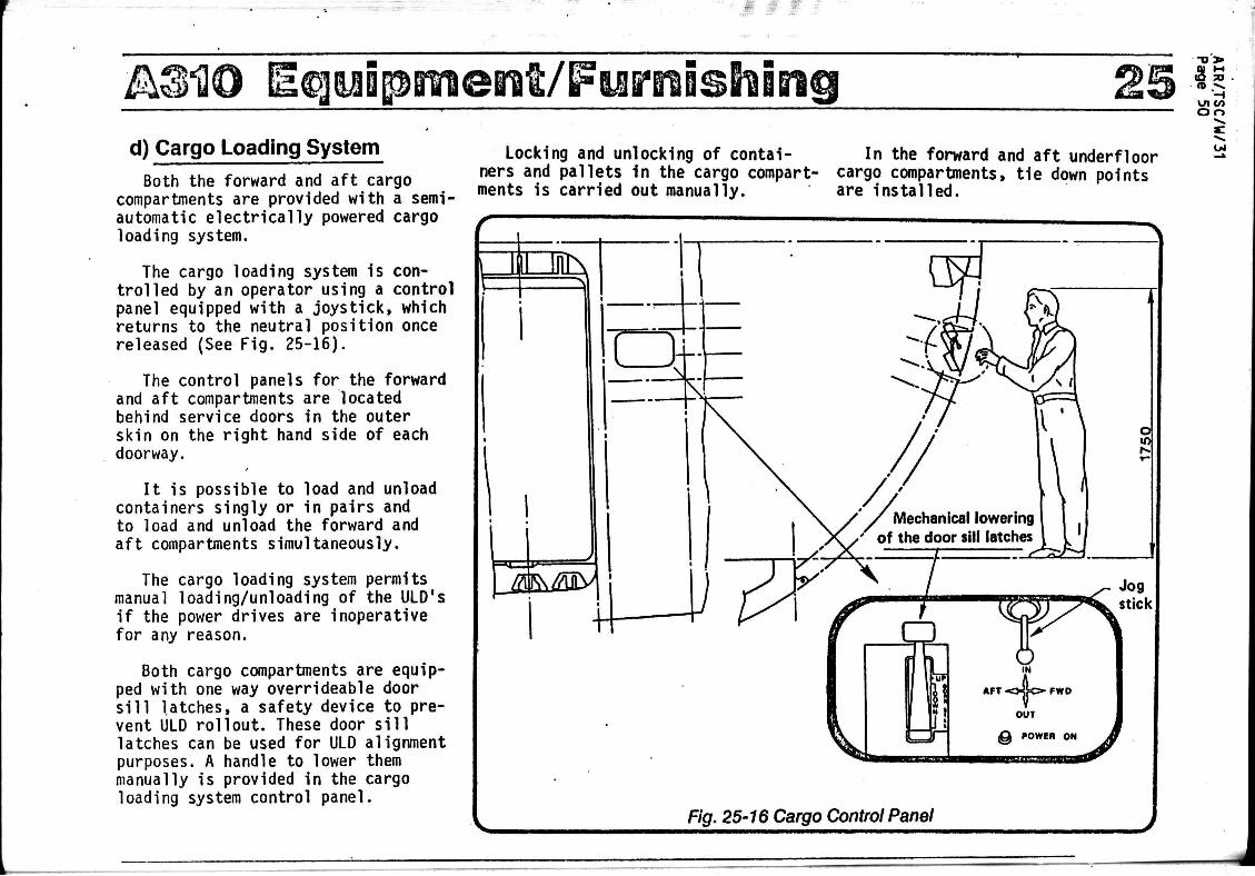
A3H0 Eeguipmenï/IFyfi'nisBiing d) Cargo Loading System Both the forward and aft cargo
compartments are provided with a semiautomatic electrically powered cargo loading system.
The cargo loading system is controlled by an operator using a control panel equipped with a joystick, which returns to the neutral position once released (See Fig. 25-16).
The control panels for the forward and aft compartments are located behind service doors in the outer skin on the right hand side of each doorway.
It is possible to load and unload containers singly or in pairs and to load and unload the forward and aft compartments simultaneously.
The cargo loading system permits manual loading/unloading of the ULD's if the power drives are inoperative for any reason.
Both cargo compartments are equipped with one way overrideable door sill latches, a safety device to prevent ULD rollout. These door sill latches can be used for ULD alignment purposes. A handle to lower them manually is provided in the cargo loading system control panel.
Locking and unlocking of containers and pallets in the cargo compartments is carried out manually.
In the forward and aft underfloor cargo compartments, tie down points are installed.
q> n (O SO n .»».
- i i n GO O o
U4
Fig. 25-16 Cargo Control Panel J

AIR/TSC/W/31 Page 51
FICHE DE PROPOSITION 7/82 NCCD: voir rubrique 2
1 - Désignation du produit -
Equipements de communication de bord, ensembles, sous-ensembles,
leurs parties et pièces détachées identifiables.
2 - Classification tarifaire - Positions nouvelles demandées -
NCCD TSUS
Interphones de bord, combinés téléphoniques
Commutateurs d'écoute, casques d'écoute
Boîtes de commande, boîtes de jonction, supports de branchement (racks)
Enregistreurs de voix (cockpit voice recorder)
Câbles coaxîaux d'antennes (Feeders)
Annonceurs automatiques, reproducteurs de musique
Antennes, coupleurs d'antennes, excitateurs HF, sous-ensembles radio
Amplificateurs de puissance HF
85-13
85-22
85-19
92-11
85-23 (complément)
92-11
85-15 (complément)
85-22
T. Can
684-72 (couvert)
685-41
685-41
- Sous réserve que ces matériels ne soient pas compris dans : assem
blages et sous-assemblages de ces appareils.
3 - Exemgle d'utilisation -
Système de communication radioélectrique de bord, interphone, sono
risation cabine, enregistreur de sécurité.
Pour assurer sa propre sécurité et celle des autres aéronefs, per
mettre sa prise en charge par les services de contrôle au sol et recevoir des
instructions en vol, tout avion doit posséder un système de communication. Il
faut également assurer les contacts entre personnels de bord.

AIR/TSC/W/31 Page 52
FICHE DE PROPOSITION 7/82
Un tel système peut se décomposer en :
a) Systèmes de_communication_avec l'extérieur (services au sol et autres
avions)
. Postes HF, VHF, Selcall, ) ., ., , . .. ,..,. . , 85-15 (couvert)
radio-téléphone (
2£5S£YtSî2S£ Les émetteurs, récepteurs, émetteurs-récepteurs
sont couverts par l'Accord, par contre les sous-ensembles complémentaires tels que :
. amplificateurs de puissance, coupleurs d'antenne,
. boîtiers d'appel sélectif (Selcall),
. boîtiers de commande,
. supports de branchement (Shockmount, rack)
. décodeurs,
ne sont pas couverts puisque les parties et pièces détachées du 85-15 sont exclues de l'Accord, de même que les assemblages, et sous assemblages autres que ceux des appareils de radioguidage, de radio-détection, de radio-sondage et de radio-té lé commande.
b) Systèmes d1intercommunication de bord, personnels navigants/moyens
de communication (audio system) :
. Interphones, combinés ( g5 13 ( n o n ) téléphoniques ( " (couvert)
. commutateurs téléphoni-) Q513 ( non ) ques ( ~ (couvert)
. boîtes de jonction 85-19 \ n o n X •* ( couvert;
. microphones 85-14 (couvert) 684-72 (couvert)
. casques d'écoute- 85-22 S n o n \ 684-72 (couvert) ^ (couvert)
c) Systèmes de sécurité
. enregistreurs de voix ) / \ (cockpit voice recor- ( 92-11 , A 685-41 (couvert) der) ) (couvert)
d) Systèmes de communication vers les passagers
. (public address) 85-14 J n o n J. r (couvert)
e) Systèmes de sonorisation cabines
reproducteurs de musi-) , \ que, annonceurs automa( 92-11 ; n ° n ; 685-41 (couvert) **. N (couvert) txques ;
AIR/TSC7W/31 Page 53
FICHE DE PROPOSITION 7/82
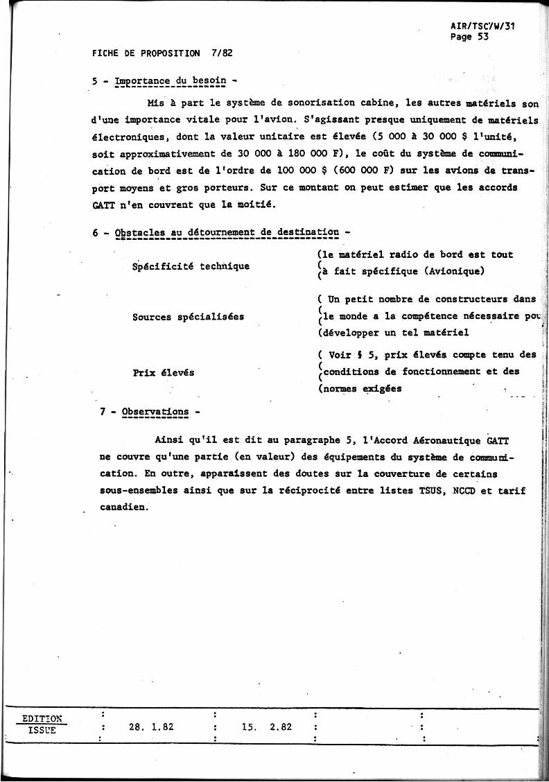
5 - Importance du besoin -
Mis à part le système de sonorisation cabine, les autres matériels son
d'une importance vitale pour l'avion. S'agissant presque uniquement de matériels
électroniques, dont la valeur unitaire est élevée (5 000 à 30 000 $ l'unité,
soit approximativement de 30 000 à 180 000 F), le coût du système de communi
cation de bord est de l'ordre de 100 000 $ (600 000 F) sur les avions de trans
port moyens et gros porteurs. Sur ce montant on peut estimer que les accords
GATT n'en couvrent que la moitié.
6 - Obstacles au détournement de destination -
Spécificité technique
Sources spécialisées
Prix élevés
7 - Observations -
(le matériel radio de bord est tout
/à fait spécifique (Avionique)
( Un petit nombre de constructeurs dans
,1e monde a la compétence nécessaire pou
(développer un tel matériel
( Voir S 5, prix élevés compte tenu des ( ( conditions de fonctionnement et des
(normes exigées
Ainsi qu'il est dit au paragraphe 5, l'Accord Aéronautique GATT
ne couvre qu'une partie (en valeur) des équipements du système de communi
cation. En outre, apparaissent des doutes sur la couverture de certains
sous-ensembles ainsi que sur la réciprocité entre listes TSUS, NCCD et tarif
canadien.
EDITION ISSUE
: 28.
-
1.82 : 15. 2.82 : •
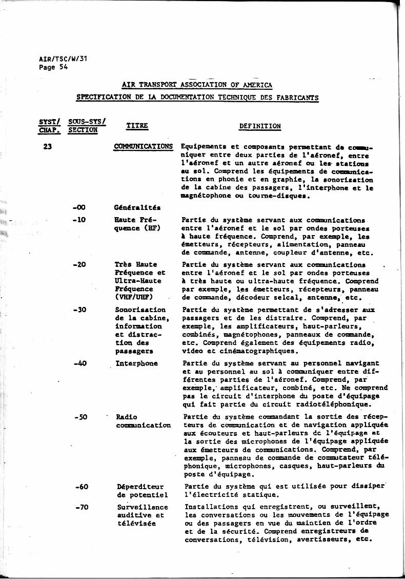
AIR/TSC/W/31 Page 54
AIR TRANSPORT ASSOCIATION OF AMERICA
SPECIFICATION DE LA DOCUMENTATION TECHNIQUE DES FABRICANTS
SYST/ SOUS-STS/ CHAP. SECTION
23
-00
-10
-20
-30
-40
-50
-60
-70
TITRE
COMMUNICATIONS
Généralités
Haute Fréquence (HF)
Très Haute Fréquence et Ultra-Haute Fréquence (VHF/UHF)
Sonorisation de la cabine, information et distraction des passagers
Interphone
Radio communication
Déperditeur de potentiel
Surveillance auditive et télévisée
DEFINITION
Equipements et composants permettant de communiquer entre deux parties de l'aéronef, entre l'aéronef et un autre aéronef ou les- stations au sol. Comprend les équipements de communications en phonie et en graphie, la sonorisation de la cabine des passagers, l'interphone et le magnétophone ou tourne-disques.
Partie du système servant aux communications entre l'aéronef et le sol par ondes porteuses à haute fréquence. Comprend, par exemple, les émetteurs, récepteurs, alimentation, panneau de commande, antenne, coupleur d'antenne, etc.
Partie du système servant aux communications entre l'aéronef et le sol par ondes porteuses à très haute ou ultra-haute fréquence. Comprend par exemple, les émetteurs, récepteurs, panneau de commande, décodeur selcal, antenne, etc.
Partie du système permettant de s'adresser aux passagers et de les distraire. Comprend, par exemple, les amplificateurs, haut-parleurs, combinés, magnétophones, panneaux de commande, etc. Comprend également des équipements radio, video et cinématographiques.
Partie du système servant au personnel navigant et au personnel au sol à communiquer entre différentes parties de l'aéronef. Comprend, par exemple,' amplificateur, combiné, etc. Ne comprend pas le circuit d'interphone du poste d'équipage qui fait partie du circuit radiotéléphonique.
Partie du système commandant la sortie des récepteurs de communication et de navigation appliquée aux écouteurs et haut-parleurs de l'équipage et la sortie des microphones de l'équipage appliquée aux émetteurs de communications. Comprend, par exemple, panneau de commande de commutateur téléphonique, microphones, casques, haut-parleurs du poste d'équipage.
Partie du système qui est utilisée pour dissiper l'électricité statique.
Installations qui enregistrent, ou surveillent, les conversations ou les mouvements de l'équipage ou des passagers en vue du maintien de l'ordre et de la sécurité. Comprend enregistreurs de conversations, télévision, avertisseurs, etc.
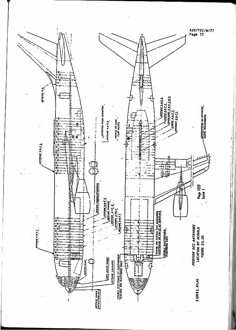
AIR/TSC/W/31 Page 55
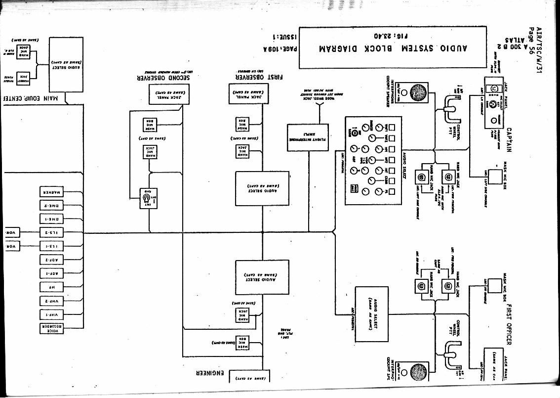
(jtn n tmn)
J i n OXfM
a»r
( i « « i r MnnJ 13111S oiont
J31N3D'din03 NIVW
KOA J-
L
J - 3 H Q
i w o | s
I - Î I I
J3IOA
pans si
V60P30Vd
«iAaasao QNOoas
çun »r » r r ) HNVd « 5 * f
^
>0I air»
f j « o «r i x r r j
3 in
t
«3AH3SflO ÎSUIJ
OtrK >9N
wvaovia X3019 W31SAS oianv
31»
( u n t r I K M J
3 i n ON»M
JUMIt «TON» A i r M M W 11 IWI M O N
xaaiic oion»
JH- I IS oionv
(uns* ton)
5IB
(uanimn)
U33NION3
W W i n j u
(a/ra l e « n r r ;
S ,-J O-O O-iD
« lao-sa O-O 0-*a m O-Sa i © 0-»D
SVliV -o > 01 M
* 5 a oos v ui ̂
O" O
1/4
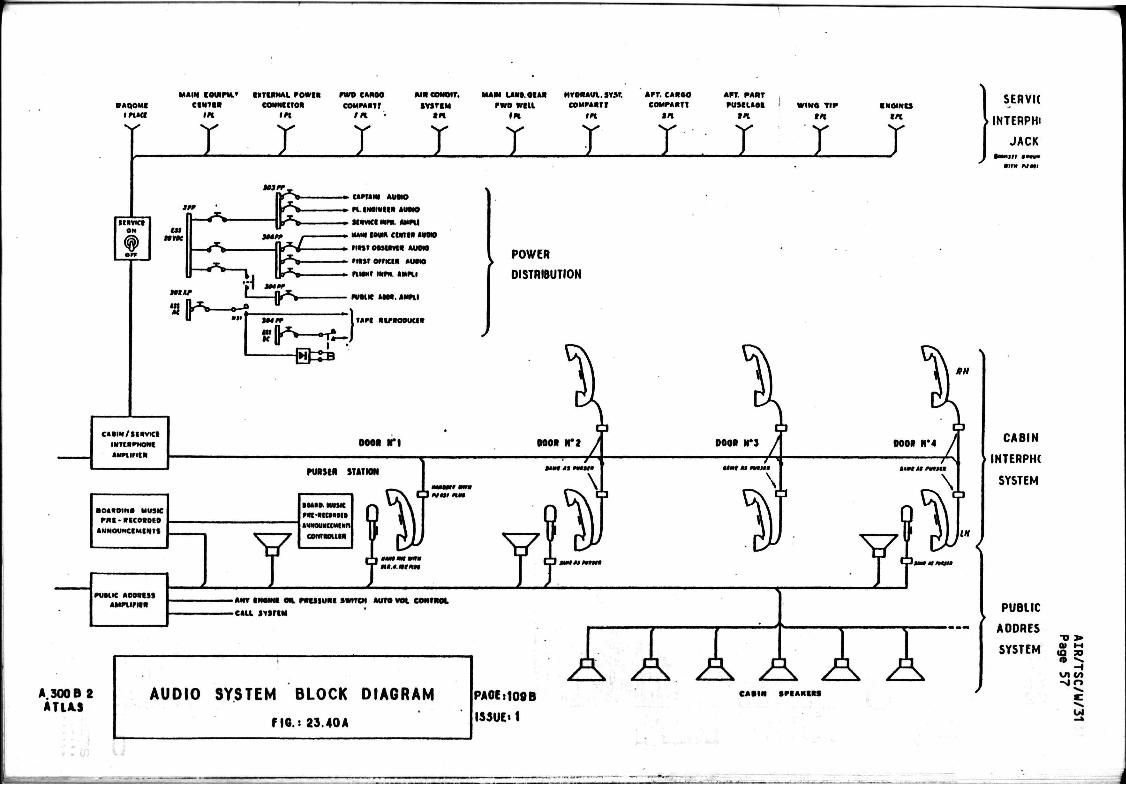
NAQO MI
i m «
M A I N COUIFM.*
e m u » in
U T t R K A L FOWtR
CONNECTOR
in
FWD CANOO
COMPAATJ
A M e o M o i r .
S T S T C M
MAIN LAMR.QtAR
r wo will IK
H T 0 N A U 1 . 3 Y M .
C O M P A A T T
AFT. CARGO
COMPAATt
tn
AFT. PART F U S C I A 0 I W I N t t T I F
tn
T T T T T T T -• T I T
I K V I C f OH
CAPTAIN AUOiO
« tt.lNM*ICR AOTM
S I A V K I M P * AMPII
MAW IOWA CMTIR M M
« I I I » M M R AUDIO
r m t o i r i c e * A U D I O
FIMMT INPH AMPII
PUAUC M M . AHFl l
TAPI RlPAOOUCIf
POWER
DISTRIBUTION
©SB
C A I I N / S t A V K I
INTCAPWDNt
AUPIIPItR oeea r i
PURJIR SHIIOH
• OAADINA MUSIC
F N I - A I C O I 0 C O
AMNOUNCIMINT1
PUAUC AD0RIS» AMFI IF I IA
I • OHO MUJIC
F A f R R I A N I
IWKMMUMIlin
CONTCOlllR
Ç J w * w urn
AtJNAtArfAM
• ANT I N O I N I OIL F R U S U R t SWITCH AUTO V o l CONTROL
•CALL S Y S r t M
A.300B 2 ATIA.S
AUDIO SYSTEM BLOCK DIAGRAM
FIG.: 23.40A
PAGE:109B
ISSUE»1
rxx A C A R I N S F I A K I A S
SERVK
> INTERPW
JACK •otMjrr » • « •
CABIN
>INTERPW
SYSTEM
PUBLIC
A0DRES
SYSTEM T J J » 01 H I
t Q 3D fl» •> -
- I ui c/> - g o
id
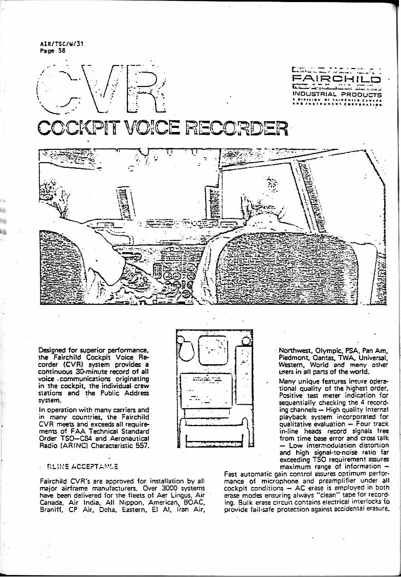
AIR/TSC/W/31 Page 58
..a. FAIRCHILD INDUSTRIAL PRODUCTS » O I V I I I O N e l I I K C M I I B t i « l * i
COCKPIT V02CE RECORDER
Designed for superior performance. The Fairchild Cockpit Voice Recorder (CVR) system provides a continuous 30-minute record of all voice -communications originating in the cockpit, the individual-crew stations and the Public Address system.
In operation with many carriers and in many countries, the Fairchild CVR meets and exceeds all requirements of FAA Technical Standard Order TSO—C84 and Aeronautical Radio {ARINQ Characteristic 557.
'-.'.' ^
Fairchild CVR's are approved for installation by all major airframe manufacturers. Over 3000 systems have been delivered for the fleets of Aer Lingus. Air Canada. Air India, All Nippon, American^ BOAC, Braniff. CP Air. Delta, Eastern. El AI. Iran Air.
Northwest, Olympic. PSA. Pan Am. Piedmont. Qantas. TWA, Universal. Western, World and many other users in all parts of the world. Many unique features insure operational quality of the highest order. Positive test meter indication for sequentially checking the 4 recording channels — High quality internal playback system incorporated for qualitative evaluation — Four track in-line heads record signals free from time base error and cross talk — Low intermodulation distortion and high signal-to-noise ratio far exceeding TSO requirement assures maximum range of information —
Fast automatic gain control assures optimum performance of microphone and preamplifier under all cockpit conditions — AC erase is employed in both erase modes ensuring always "clean" tape for recording. Bulk erase circuit contains electrical interlocks to provide fail-safe protection against accidental erasure.
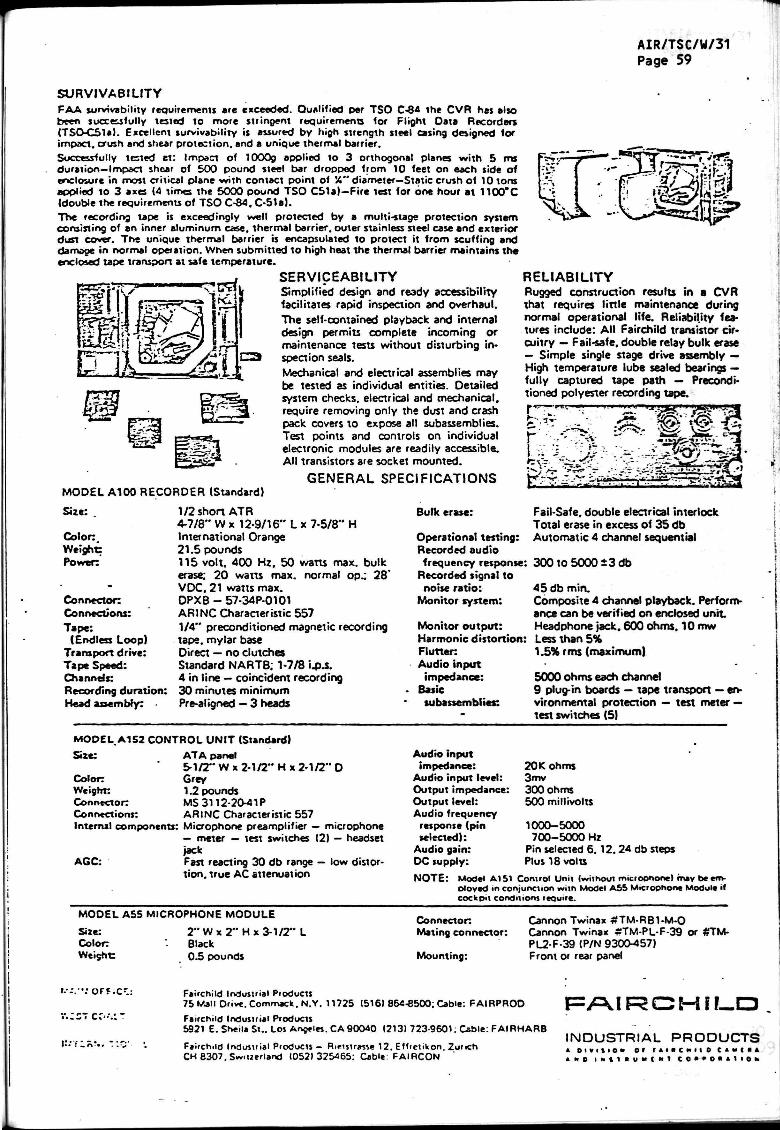
AIR/TSC/W/31 Page 59
S U R V I V A B I L I T Y
FAA survivability requirements are exceeded. Qualified per TSO C-84 the CVR has also been successfully tested to more stringent requirements for Flight Data Recorders (TSO-C51a). Excellent survivability is assured by high strength steel casing designed for impact, crush and shear protection, and a unique thermal barrier. Successfully tested et: Impact of 1000g applied to 3 orthogonal planes with 5 ms duration—Impact shear of 500 pound steel bar dropped from 10 feet on each side of enclosure in most critical plane with contact point of Î4" diameter—Static crush of 10 tons applied to 3 axes (4 times the 5000 pound TSO C51a)—Fire test for one hour at 1100°C (double the requirements of TSO C-84, C-51e). The recording tape is exceedingly well protected by a multi-stage protection system consisting of an inner aluminum case, thermal barrier, outer stainless steel case and exterior dust cover. The unique thermal barrier is encapsulated to protect it from scuffing and damage in normal operation. When submitted to high heat the thermal barrier maintains the enclosed tape transport at safe temperature.
SERVICEABILITY Simplified design and ready accessibility facilitates rapid inspection and overhaul. The self-contained playback and internal design permits complete incoming or maintenance tests without disturbing inspection seals.
Mechanical and electrical assemblies may be tested as individual entities. Detailed system checks, electrical and mechanical, require removing only the dust and crash pack covers to expose all subassemblies. Test points and controls on individual electronic modules are readily accessible. Al l transistors are socket mounted.
GENERAL SPECIFICATIONS
Era
MODEL A100 RECORDER (Standard)
Size: .
Colon Weight: Power:
Connector: Connections: Tape:
(Endless Loop) Transport drive: Tape Speed: Channels: Recording duration: Head assembly:
H 1/2 short ATR 4-7/8" W x 12-9/16" L x 7-5/8" International Orange 21.5 pounds 115 vol t . 400 Hz. 50 watts max. bulk erase: 20 watts max. normal op.: 28 ' VDC. 21 watts max. DPXB - 57-34P-0101 ARINC Characteristic 557 1/4" preconditioned magnetic recording tape, mylar base Direct — no clutches Standard NARTB; 1-7/8 i.p.s. 4 in line — coincident recording 30 minutes minimum Pre-aligned — 3 heads
RELIABILITY Rugged construction results in a CVR that requires l itt le maintenance during normal operational life. Reliability features include: A l l Fairchild transistor circuitry — Fail-safe, double relay bulk erase — Simple single stage drive assembly — High temperature lube sealed bearings — fully captured tape path — Preconditioned polyester recording tape. r * r w - m.
u ram* 'msm*S»***mj,
- WW %
Bulk erase:
Operational testing: Recorded audio frequency response:
Recorded signal to noise rat io:
Monitor system:
Monitor output : Harmonic distort ion: Flutter: Audio input
impedance: Basic subassemblies:
Fail-Safe, double electrical interlock Total erase in excess of 35 db Automatic 4 channel sequential
300 to 5000 ±3 db
45 db min. Composite 4 channel playback. Performance can be verified on enclosed u n i t Headphone jack. 600 ohms, 10 mw Less than 5% 1.5% rms (maximum)
5000 ohms each channel 9 plug-in boards — tape transport — environmental protection — test meter — test switches (5)
MODEL A152 CONTROL UNIT (Standard)
Size: ATA panel S I / 2 " W x 2-1/2" H x 2-1/2" D
Color: Grey Weight: 1.2 pounds Connector: MS 3112-20-41P Connections: ARINC Characteristic 557 Internal components: Microphone preamplifier — microphone
— meter — test switches (2) — headset jack
AGC: Fast reacting 30 db range — low distort ion, true AC attenuation
Audio input impedance:
Audio input level: Output impedance: Output level: Audio frequency
response (pin selected):
Audio gain: DC supply:
20Kohms 3mv 300 ohms 500 millivolts
1000-5000 700-5000 Hz
Pin selected 6.12.24 db steps Plus 18 volts
NOTE: Model AI 51 Control Unit (without miciophonel may beem-oioyed m conjunction with Model A55 Microphone Module il cockpit conditions leauire.
MODEL A55 MICROPHONE MODULE
H x 3-1/2" Size: Colon Weight:
2 " W x 2" Black 0 3 pounds
Connector Mating connector:
Mounting:
Cannon Twinax #TM-RB1-M-0 Cannon Twinax £TM-PL-F-39 or #TM-PL2F-39 (P/N 9300-457) Front or rear panel
!.•--.••: o f f . c -
•.•.:c7cc-v--
ir. 'Yiô!.. V.rj
Fairchild Industrial Products 75 Mall Dr.ve. Commack.N.Y. 11725 (516) 864-8500; Cable: FAIRPROD Fairchild Industrial Products 5921 E. Sheila St.. Los Angeles. CA 90040 (2131 723-9601; Cable: FAIRHARB
Fairchild Industrial Products - Rietsuasse 12. EHrctikon. Zurich CH e307. Switzerland (052)325465: Cable FAIRCON
FAIRCHILD INDUSTRIAL PRODUCTS * o i v i i i o K or r t i i c m i o c • • I l i A N D I N l t f t U M C M I C 0 * » 0 * A 1 1 0 h

AIR/TSC/W/31 Page 60
czszzz: rra
INDUSTRIAL PRODUCTS
COCKPIT VOICE RECORDER OVERHAUL
D. Group Assembly P a r t s L i s t
ELAPSED TIME COUNTER (OPTIONAL)
i
! • -
INVERTER (OPTIONAL)
CONTROL
AREA MICROPHONE(OPTIONAL)
Cockpi t Voice Recorder System (Model A100 Shown) F igu re 20
23-70 108
O c t o b e r 1 5 , 1 9 ^ 2

T F = / = \ I R C H I L P fcni* • . « w . -. .• ^ -•--• 'rtSl
INDUSTRIAL PRODUCTS
COCKPIT VOICE RECORDER OVERHAUL
AIR/TSC/W/31 Page 61
.
Janua ry 1 , 1967
Main Recorder Assembly A100, A113 F igure 21
23-70 109

A@HO (D@eiraEmyirai<eati@Bi
CONTENTS
1 GENERAL 2 ANTENNAE 3 EQUIPMENT INSTALLATION 4 SYSTEMS DESCRIPTION
1 GENERAL In accordance with the fail safe
principle adopted for the complete aircraft, a dual radio and navigation system is provided in the A310. Both pilot and co-pilot have an integrated instrument system combining heading, attitude, flight director and radio information.
All radio systems are designed such that a failure is indicated or immediately recognizable by comparison.
The location of the avionic equipment (see fig."23-1) has been carefully studied and the coaxial length requirement has been taken into account.
- The HF antenna coupler is close to the HF antenna
- The radio altimeters are close to the antennas.
Fig. 23-1 Avionic Equipment Location " \
H F antenna coupler
Forward equipment bay — Weather radar
\ _ Main equipment bay - Avionic equipment - Communication - Navigation - AFCS
Aft equipment bay - Voice recorder - Flight recorder - Underwater locator (option)
TJ > 0) l-t «Û TO to «v
- I C* GO N O
W
Plugs and sockets and wire terminations are of the crimped type. Radio wiring is separated from other wiring and routed clear of hot air ducts. Protection is provided to ensure that electronic units, components, connectors and cables will not be contaminated by water, hydraulic and other fluids. If not otherwise stated; the equipment mounting and wiring is in accordance with ARINC standardization.
Adequate space is provided to allow for system growth and development during the operational life of the aircraft.
Static Dischargers
Static dischargers are installed on the wing and tail unit trailing edges to minimize corona discharge Interference resulting from precipitation, static or engine charging.

M>cOû ©omuïïBunicsition 2 ANTENNAE (see fig. 23-2 for location)
The following antennas are installed :
VHF-COMM. omnidirectional 2
VHF-NAV.omnidirectional Dual
LOCALIZER Dual
GLIDE SLOPE Dual
MARKER 1
ADF 1 (2nd optional )
DME omnidirectional 2
Weather radar scanner (+ 90° azimuth, + 15° pitch, X band,30 Inches) 1
Radio altimeter (low range) 2 sets
HF 1
Provisions are made for the following antennas :
Third VHF-COMM.omnidirectional 1 space provision
OMEGA 1 space provision
Maximum practical decoupling is provided between each VHF antenna and between VHF antenna and VOR antenna.
The dual omnidirectional VHF/NAV antenna is connected by two separate coaxial cables to the receivers. The same principle is adopted for the GLIDE SLOPE and LOCALIZER antennas.
DME antennas are located to avoid mutual interference between each other and the ATC transponder antennas.
Radio altimeter antennas are located to avoid mutual interference between each other and the DME antennas. The weather radar radome is designed so as to be capable of being opened or closed by one man.
All antennas are removable from outside the aircraft, requiring no disassembly of cabin or cargo compartment linings.
-o > Q> »-i IQ TO
H &• «/>
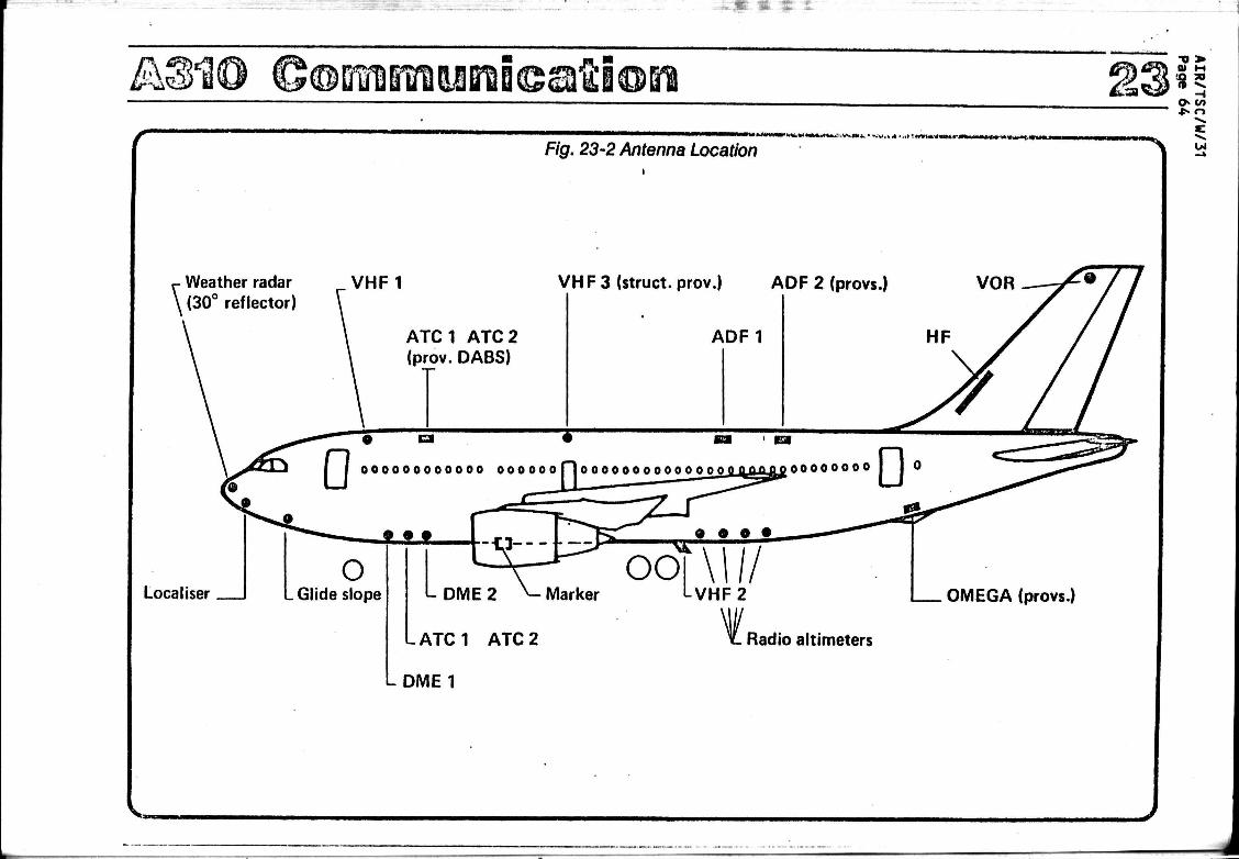
--«• * •¥ £ ; I
AS10 Goimi'rounicatâion Fig. 23-2 Antenna Location
'.*niiT<iiiiriTli>iiiiiMi<i n o u n
Weather radar (30° reflector)
Localiser
VHF1 VH F 3 (struct, prov.) ADF 2 (provs.)
ATC1 ATC2 (prov. DABS)
o _ Glide slope
•o > 01 M
u i
L. DME 2 >- Marker
LATC1 ATC2
LDME1
OMEGA (provs.)
Radio altimeters
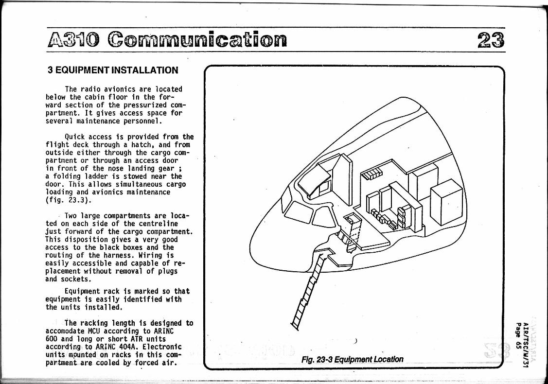
uroicsAion 3 EQUIPMENT INSTALLATION
The radio avionics are located below the cabin floor in the forward section of the pressurized compartment. It gives access space for several maintenance personnel.
Quick access is provided from the flight deck through a hatch, and from outside either through the cargo compartment or through an access door in front of the nose landing gear ; a folding ladder is stowed near the door. This allows simultaneous cargo loading and avionics maintenance (fig. 23.3).
Two large compartments are located on each side of the centreline just forward of the cargo compartment. This disposition gives a very good access to the black boxes and the routing of the harness. Wiring is easily accessible and capable of replacement without removal of plugs and sockets.
Equipment rack is marked so that equipment is easily identified with the units installed.
the racking length is designed accomodate MCU according to ARINC 600 and long or short ATR units according to ARINC 404A. Electronic units mounted on racks in this compartment are cooled by forced air.
to TJ 3»
CO 30
n -̂ H
o co W1 o
c

^310 ChMnmunicaftion 23 *S 4 SYSTEMS DESCRIPTION
The communication system includes all transceivers necessary for transmitting and receiving messages from other airplanes and from ground stations. (See Fig. 23.4)
Following installations are provided for the communication system :
SYSTEM
H F (option)
VHF
Se leal
Passenger address system
Tape reproducer (option)
Audio-Interphone system
Cockpit voice recorder V
ARINC
719
716
714
715
539 A
—
NUMBER PER AIRCRAFT
0
2
1
1
0
1
1
REMARK
Full provision for No. 1
Space provision for VHF No. 3
Full provision for one music and prerecorded announcement system
(B.F.E)
J
O* r>
W

A: 110 ©©MiMaBT}i<eati@Bi 23 f
1 1
IO I VL
O \ _
^
Çj
Ç|
Audio tetoctor câpt
Audio selector F/0
Audio «elector 3rd crew member
Audio selector 4th crew.membec
Option
Option Audio «elector avionics
V O R t
V 0 R 2
ADF 1
A 0 F 2 ( 0 p t . )
0 M E 1 •'
DME2
MARKER
* *
•»-
— -
Inttrphont
Audio
integrating
system
Flight Interphone
Fig. 23-4 Con
f—
- 4 i i L
"
H F radio set control
VHF 1 com.
control pend
VHF 2 com. control panel
Selcal control panel
L i i l
J . | 1
—
-
imu
Passenger eddreu
Cockpit voice recorder
microphone monitor
nications Block L
h —
5/as
H F trensceiver
__̂r.
VHF 1 transceiver
1 VFH 2 transceiver !
,
Selcal
\
Service interphone
i
Fuselage ground connections
Passenger address loudspeaker Installation
Recorder cockpl'voice
f
tram
n r enienna ana antenne coupler |tuner-HF|
« J
-+—
=r
VHF 1 antenne
VHF 2 antenna
--+*r

AS10 ©oinrairaauroicslliiQn "0 > 01 ID IV
M .50
^. H o> t/ j 00 O
a) HF System (Full provision)
A single system allows two way long range communications with ground stations and other aircraft on the frequency range of 2 to 29.999 MHz providing a selection capability of 28.000 channels spaced 1 KHz apart (See Fig. 23.5)
Description
The HF system comprises :
- a control panel (see Fig. 23.6) located on the overhead panel
- a transceiver located in the main compartment bay (See Fig. 23.1)
- an antenna coupler and one antenna, both located in the leading edge of the vertical stabilizer (See Fig. 23.1 and 23.2)
A space provision is provided for a second HF.
Connection with other systems
The HF system is connected with :
- the flight interphone which provides microphone and push-to-talk signals
- the flight recorder which receives a ground signal during HF transmission
- the radio master supply panel.
« • • « < « * •-! .V.» • -. -*,
•
HF
tntvnns
, i
HF antenna
coupler
Fig. 23-5 H F. Block Diagrarr
HF convoi
panel
HF
transceiver
)
•
Flight
Interphone Sdcet
Oi
Mmmmm mumiMifmjK.Tm*%M**Mtmm4m*^**rwMu>im • n
Fig. 23-6 H F. Control Panel

A3H0 Communication b)VHFSystem (Fig. 23-7)
The very high frequency (VHF) system is one of the means of communication between ground stations and the crew and between different aircraft.
The aircraft is equipped with two identifical VHF installations which are idependent of each other.
Space provision has been provided for installation of a third VHF system.
The VHF transceivers operate in the range of 118 to 139.95 MHz frequency with 25 kHz spacing.
The VHF system comprises :
- two control panels (see Fig. 23.8) located on the pedestal
- two transceivers located in the main equipment bay (see Fig. 23.1)
- two antennas VHF 1 and VHF 2 (see fig. 23.2)
The VHF system is connected with :
the flight interphone which provides microphone and push-to-talk signals the flight recorder (flight data acquisition unit) the sel cal system -
V H M
•nunn* '
VHF COM.1 control ptntl
VHF1
trinicolvor
VHF 2
•nttnni
VHF 2
kaniorivor
,,
VHF COM. 2 control canot
Flight dou •oqubltlon
unit
T Flight
IntcrpnofM
T
1
Balcal
Fig. 23-7 V H F. Block Diagram
VHF COMM
»l8.00l-@-fÏÏÔÔ TFR
Fig. 23-8 VHF. 1/2 Control Panel I I
•D I» 01 1-1 (Q TO IP «>»
H o» c/> •Ort
Oi

À @[FMiMi©ati©ii •o > 0) M (O 71 «S —*
-i O o
04 c) Selective Calling System
The Selcal system allows the ground operator to call a single aircraft among a group of aircraft in flight without requiring the crew to listen in constantly on the ground station frequency. The calling code
is identified by a combination of four letters selected from among the twelve available letters 'A to M'.
The Selcal system comprises :
- a control panel (see fig. 23.9) - a Selcal decoder equipped with
two channels.
- a code selection box
The decoder accepts inputs from VHF1 and 2 and VHF3 or HF1 and 2 if installed. Selcal indication and reset functions are included in the control panel.
SELCAL
HlVHF j ]
ll 1 — ! " i
VHF 2
VHF 1
•rnïv»
1 1 1 1
n — h "L J'I
HFI
Fig. 23-9 SELCAL Control Panel J V
r
VHF 2
receiver
\ — \ i
i l I i L
w — 1 ^
HF
receiver
— — - * : —
1 i i J
VHF1
receiver
Selcal
control
panel
Selcal decoder
Channel
No. 1
Channel
No. 2
**
i
Selcal 1
indicator
light
^ \
Selcal 2
indicator
light
Audio
warning
Fig. 23-10 SELCAL Block Diagram ,
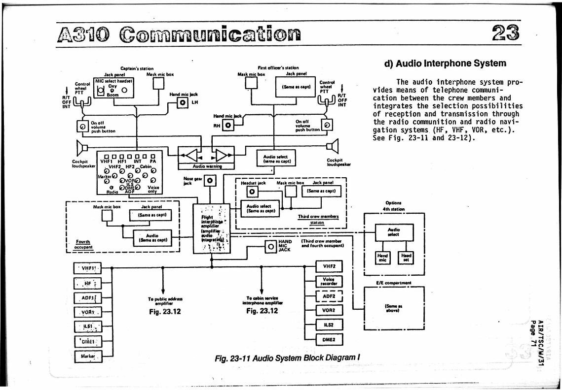
A©HO ©©01ÎB!ïïl5.QBli©ati©BÎ
Control I wheel Î PTT
R/T OFF INT
Capl t in ' i u n i o n
Jack panel Mask mie box
First o l l i ce t ' i t u t l o n
M i l k m i t bo» J ick panel
M l C i e l t c t heedsel Oxy © O
Boom a Hand mic )ack
L H
On o i l volume push but ton
D> Cockpit loudspeaker
P* {Stmt I I capt)
Control
PTT
H i n d mic
RH rr
a a a a a a a VHF1 HF1 INT PA
. VHF2 H F 2 ^ C e b « »
M a r k e r © 0 0
0 Ovpn0 0 O 0 O M H 0 Voice Radio
U only
3-E <p s> Audio o w n i n g
On o i l volume push but ton
(UJ)
[0"
R/T OFF INT
Audio select (lame a i capt)
< Cockpit loudspeaker
Note gear f»ck
Mask mic box Jack panel
(Same a i capt)
Fourth occupant
Audio (Same at capt)
m w ^ m 1
Headtet jack Matk mic box Jack panel
n i g h t ". in terphone" amplif ier (amplifier i audio «• : integrating) 1
• V ' it '
• VHF1Ï
. . H F >
A U H |
! Y 0 B r •
1 ' •**£*.' 'CM£1
Marker
-
To
F
Audio select (Same as capt)
(Same as capt)
Third crew members
station
I n : 1 HAND MIC JACK
(Third crew member and four th occupant)
H To public address
amplifier
Fig. 23.12
To cabin service interphone amplifier
Fig. 23.12
VHF2
Voice recorder
A 0 F 2 I
- t V 0 R 2
ILS2
0 M E 2
d) Audio Interphone System
The audio Interphone system provides means of telephone communication between the crew members and integrates the selection possibi l i t ies of reception and transmission through the radio communition and radio navigation systems (HF, VHF, VOR, e tc . ) . See Fig. 23-11 and 23-12).
Options
4 th station
Fig. 23-11 Audio System Block Diagram I
-o > a» M ca 70 » S
H -» r»
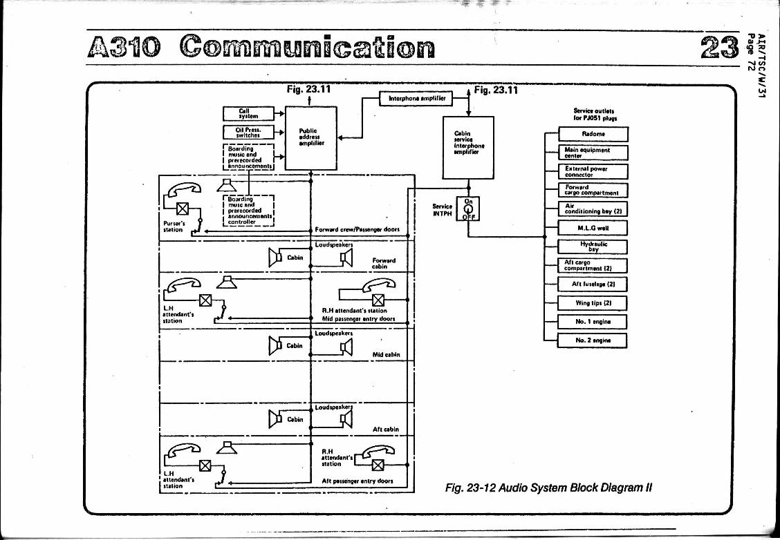
A3tù fâ@mm%Mm<&&tmm 4 Fig. 23.11
Call system
Oil Pre». switches
j Boarding ; I music and 1 », | prerecorded I |_announcementsJ
^Boarding T I muse and | j prerecorded i I announcements: ! controller '
. attendant i _ f -I station Ç . _
R.H attendant'i station Mid passenger entry doors
Mid cabin
_ _ _ _ _ | Loudspeakers
Aft cabin
R.H attendant's station
Aft passenger entry doors
Service outlets for PJ051 plugs
Radome
Main equipment center
External power connector
Forward cargo compartment
Air conditioning bay (2)
M.L.G well
Hydraulic bay
Aft cargo compartment (2)
Aft fuselage (2)
Wing tips (2)
No. 1 engine
No. 2 engin*
Fig. 23-12 Audio System Block Diagram II

WW BlB©aui©[il
- Flight Interphone System Description
The f l i g h t interphone i ns ta l l a t i on comprises (See F ig . 23-13 and 23-14)
- 3 audio selector panels (as per F ig . 23-15)
Loudspeaker
Intercom lever
Oxygen mask mike
Jack box panel
Hand mike
Hand mike jack
- 4 jack boxes - 2 loudspeakers
- 2 interphone radio push-to-talk switches on handweels
- 1 4th occupant push-to-taIk switch
1 ground connection on the nose gear
4 oxygen mask microphones
3 hand microphones
3 boomsets
1 headset
Loudspeaker
Intercom lever
Oxygen mask mike
Hand mike
Hand mike jack
Jack box panel
Audio panel Fig. 23-13 Flight Interphone Location
•o > 0) HI (O »
n ^
id r»
..-M-*- * ' w r » ' W f l i

A®H0 ©oroBtmuinicaiûion £,:sa '
0). M (O »
H -vl «/»
F/g. 23-15 Audio Selector Panel
Fig. 23-14 Flight Interphone Location
Maintenance panel
Hand mike
.Jack box panel
For 3rd Crew Member
Audio selector panel
L Jack box panel
Hand mike -

^©HÛ ©@Bifôûifiî™i<eafti®ei
Fig. 23-16 Cockpit Voice Recorder - Block Diagram
Power supply on
engine running or
aircraft in flight
Erase
Microphone
monitor
assembly
Aircraft
on
ground
Interphone
junction
box
Cockpit
voice
recorder
- Cockpit Voice Recorder The cockpit voice recorder is
designed to record on an endless magnetic tape, crew communications and conversations during flight and to preserve such record in the event of an aircraft accident. In operation the system records four separate channels of information simultaneously on a half hour magnetic tape.
Playback is not possible unless the recorder is removed from the aircraft.
The recorded conversations and communications can be completely and instantly erased as soon as the aircraft has landed.
Description (See fig. 23-16)
The cockpit voice recorder installation consists of :
- a microphone control panel - a cockpit voice recorder
located in*front of the rear pressure bulkhead.
-o » CO JO n ^
-I uin
CJ
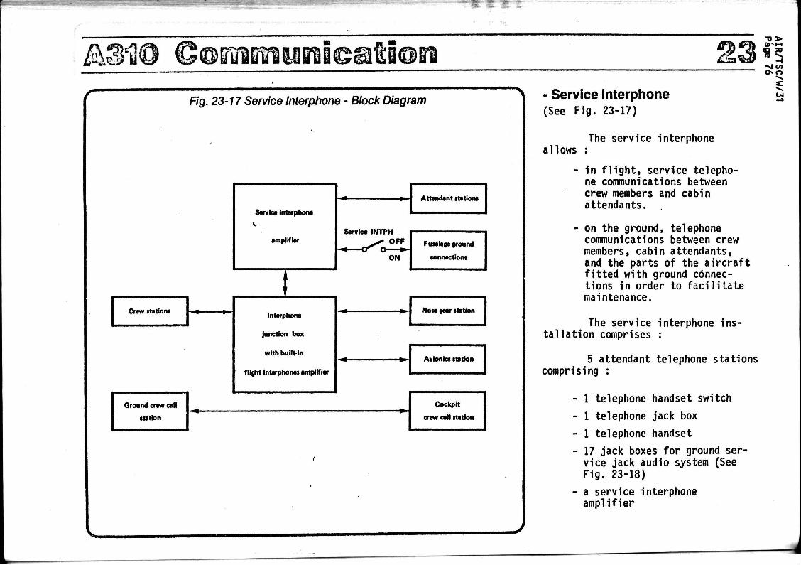
A3H0 ©@&?aBfWBii©at£i®Gi
Fig. 23-17 Service Interphone - Block Diagram
Crew nations
Ground craw call
•tation
Service interphone
amplifier
t Interphone
Junction box
with built-in
flight interphones amplifier
Servica INTPH ^ y OFF
ON
Attendant itationi
Fuselage ground
connactiom
Nota gaar station
Avionics station
Cockpit
craw call station
- Service Interphone (See Fig. 23-17)
T> > 0»-H IO TO fP >».
- I -si «/» r> o
Ul
allows The service interphone
- in flight, service telephone communications between crew members and cabin attendants.
- on the ground, telephone communications between crew members, cabin attendants, and the parts of the aircraft fitted with ground connections in order to facilitate maintenance.
The service interphone installation comprises :
5 attendant telephone stations comprising :
- 1 telephone handset switch
- 1 telephone jack box
- 1 telephone handset
- 17 jack boxes for ground service jack audio system (See Fig. 23-18)
- a service interphone amplifier
\ «

JI3130 QoïïfDimunDcsiïioBi
1. Radome 2. Electrical ground power receptacle 3. Forward cargo compartment 4. Forward air conditioning bay 5. Main landing gear forward well 6. Air conditioning bay under wing box
7. LH engine 8. Tip of LH wing 9. Rear fuselage section
10. Aft equipment bay 11. Aft cargo compartment 12. Main LH gear well
13. Main RH gear well 14. Tip of RH wing 15. RH engine 16. Electrical compartment 17. Nose landing gear
(flight interphone)
-o > 01 M
CO TO n ^ -t
> j «/»
Fig. 23-18 Service Interphone - Location of Jacks

A@1Û ©@KiirBiisBîi©atS©Bi - Passenger Address (See Fig. 23-19)
The passenger address system includes :
(a) The passenger address system, which provides :
- aural announcements to the passengers
- chime tones to alert the cabin attendants of a call from passenger' seats or lavatories
- changes in cabin signs. - calls from flight deck.
Announcements over the system to passengers are initiated through Handsets which are located at the cabin attendant's station and the flight deck.
(b) Music and prerecorded announcements (BFE).
The reproducer, which is remote controlled from the forward attendant station, broadcasts either music or recorded announcements.
The emergency oxygen announcement is automatically activated by a pressure switch, in case of rapid decompression.
Description
The passenger address system comprises :
- a passenger address amplifier - sufficient number of loudspea
kers fitted within the cabin with or without central hatrack and the lavatories.
«a -£> H
oo o
w 3 cabin attendant stations with PA announcement (L/H side only)
Full provision for :
- a music and prerecorded announcement reproducer
- a music reproducer control box.
r—
r i i i i i_
Tape
reproducer
Attendant
stations
Avionics
audio sal panel
Crew
stations
Fig. 21
"1 1
1 „ I 1
J
Passenger
address
amplifier
t Interphone
Junction box '
• r f l
.rfl LLJ
3-79 Passenger Address System - Block Diagram
Cabinet
lavatory
speakers
Attendant
speakers
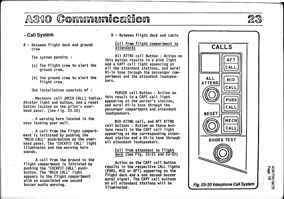
£kS°Û0 ©OBOTIifRUnflCSl&EOn
- Call System
A - Between flight deck and ground crew
The system permits :
(a) The flight crew to alert the ground crew,
(b) the ground crew to alert the flight crew.
The installation consists of :
. Mechanic call (MECH CALL) Indica-dicator light and button, and a reset button located on the pilot's overhead panel. (See Fig. 23.20)
. A warning horn located in the nose landing gear well.
. A call from the flight compartment is initiated by pushing the 'MECH CALL' push-button on the overhead panel. The 'COCKPIT CALL' light illuminates and the warning horn sounds.
A call from the ground to the flight compartment 1s initiated by pushing the 'COCKPIT CALL' pushbutton. The 'MECH CALL' light appears in the flight compartment with an associated one second buzzer audio warning.
B - Between flight deck and cabin
Call from flight compartment to attendants
All ATTND call Button : Action on this button results 1n a pink light and a CAPT call light appearing at all the attendant stations, and aural Hi-lo tone through the passenger compartment and the attendant loudspeakers.
PURSER call Button : Action on this result in a CAPT call light appearing at the purser's station, and aural Hi-lo tone through the passenger compartment and attendant loudspeakers.
MID ATTND call, and AFT ATTND call buttons : Action on these buttons result 1n the CAPT call light appearing at the corresponding attendant station and a Hi-lo tone through all attendant loudspeakers.
Call from attendant to flight deck (See Fig. 23-21 and 23-22)
Action on the CAPT call button results in the respective CALL lights (PURS, MID or AFT), appearing on the flight deck and a one second buzzer aural signal. The CAPT call buttons on all attendant stations will be illuminated.
CALLS
ALL ATTEND
AFT
CALL
MID
CALL
RESET
PURS
CALL
MECH
CALL
DOORS TEST
Fig. 23-20 Interphone Call System
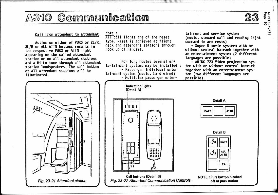
A&ao FDiiMl&18©a fk Q©B1
Call from attendant to attendant Note
Action on either of PURS or 2L/R, 3L/R or ALL ATTN buttons results in the respective PURS or ATTN light appearing on the called attendant station or on all attendant stations and a Hi-Lo tone through all attendant station loudspeakers. The call button on all attendant stations will be illuminated.
All call lights are of the reset type. Reset is achieved at flight deck and attendant stations through hook up of handset.
For long routes several en* tertainment systems may be installed
- Passenger individual enter tainment system (music, hard wired)
- Multiplex passenger enter
tainment and service system (music, steward call and reading lijjht command in arm rests)
- Super 8 movie systerm with or without central hatrack together with an entertainment system (2 different languages are possible)
- ARINC 723 Video projection system with or without central hatrack together with an entertainment system (two different languages are poss ib le) .
Ul
Indication lights (Detail A)
CED
o
pq i
* &
H7\ J
PVjM »Q 1*1 "J
:':3
Detail A
CAPT ATTN
Detail B
i fc. CAPT
3 L/R
ALL ATTN
PA
Call buttons (Detail B) Fig. 23-22 Attendant Communication Controls
NOTE : Purs button blanked off at purs station