Autonomous Ultrasonic Robot for Area...
30
A.U.R.A.S Autonomous Ultrasonic Robot for Area Scanning Project Presentation ECE 511 Fall 2014 George Mason University 12/05/2014 Group: 2 Team Members: Devaraj Dhakshinamurthy Krishna Nikhila Kalinga Gagandeep Singh Bamrah Ankita Pandey
-
Upload
vuongkhanh -
Category
Documents
-
view
217 -
download
3
Transcript of Autonomous Ultrasonic Robot for Area...

A.U.R.A.S
Autonomous Ultrasonic Robot
for Area Scanning
Project Presentation
ECE 511
Fall 2014
George Mason University
12/05/2014
Group: 2
Team Members:
Devaraj Dhakshinamurthy
Krishna Nikhila Kalinga
Gagandeep Singh Bamrah
Ankita Pandey

Motivation
•To build a robot that could utilize
various exciting features of MSP430
microcontroller.
•To develop a cost effective robot that •To develop a cost effective robot that
could also be useful in a real life
scenario.
•To design a robot that could operate
in autonomous mode in addition to
the manual mode
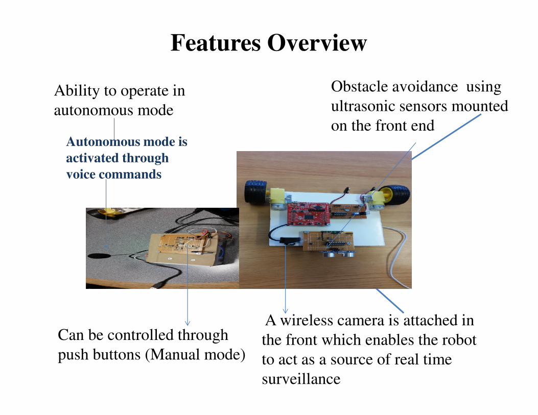
Obstacle avoidance using
ultrasonic sensors mounted
on the front end
Ability to operate in
autonomous mode
Features Overview
Autonomous mode is
activated through
voice commands
Can be controlled through
push buttons (Manual mode)
A wireless camera is attached in
the front which enables the robot
to act as a source of real time
surveillance

BLOCK DIAGRAM 1
(Handheld Controller)

BLOCK DIAGRAM 2
(A.U.R.A.S)
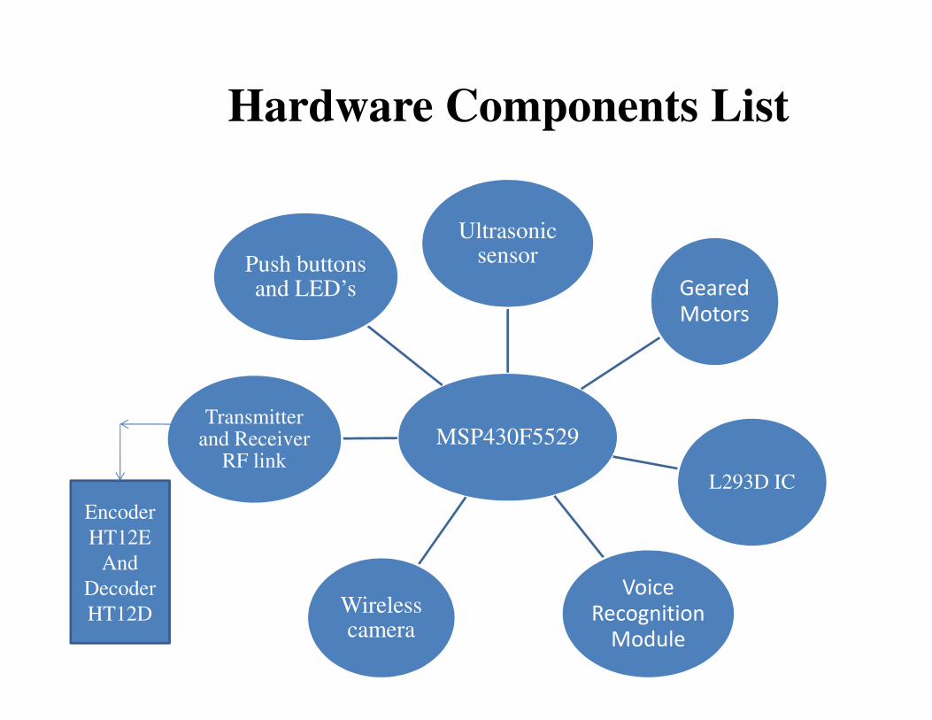
Hardware Components List
Ultrasonic sensor
Geared
Motors
Push buttons and LED’s
MSP430F5529
L293D IC
Voice
Recognition
Module
Wireless camera
Transmitterand Receiver
RF link
Encoder
HT12E
And
Decoder
HT12D

Hardware Schematic Diagram for Handheld
Controller

Hardware Schematic diagram for A.U.R.A.S

Hardware Description
1.MSP430F5529
• Ultra low power microcontroller
• Supply voltage : 3.6Volts
• Provides maximum code efficiency
through the following features:
� 16 bit powerful RISC C.P.U.
� 16 bit registers
� 16 bit timers, 63 I/O pins
� 25Mhz of clock frequency
� 128KB of programmable memory
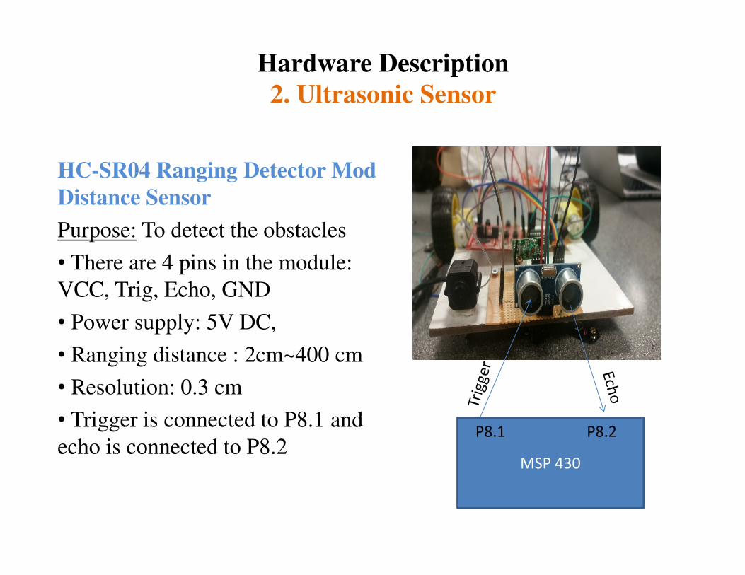
Hardware Description
2. Ultrasonic Sensor
HC-SR04 Ranging Detector Mod
Distance Sensor
Purpose: To detect the obstacles
• There are 4 pins in the module:
VCC, Trig, Echo, GNDVCC, Trig, Echo, GND
• Power supply: 5V DC,
• Ranging distance : 2cm~400 cm
• Resolution: 0.3 cm
• Trigger is connected to P8.1 and
echo is connected to P8.2MSP 430
P8.1 P8.2

WORKING OF ULTRASONIC SENSOR
Formula used:
Distance (obstacle from the robot) = Time (from trigger to echo pin= high) x speed
of sound m/s)/ 2

Hardware Description3.L293D
Purpose: Current amplifier for MSP430 for
driving geared motors
• One L293D motor driver is used
• The two H-bridges of L293D are
connected to two motors at the rear end
Inputs from Microcontrollers:
M1-B =P2.4 M1-A =P1.5M1-B =P2.4 M1-A =P1.5
M2-B =P1.4 M2-A =P1.3
Enable Pins:
1-2 EN
3-4 EN
Output to 2 Motors:
1Y,2Y
4Y,3Y
GND-4,5,12,13 connect to microcontroller
ground
Directly connected to 5V
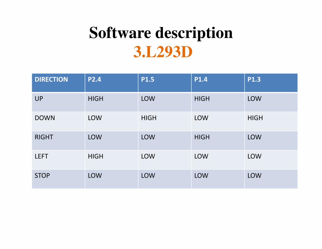
Software description
3.L293D
DIRECTION P2.4 P1.5 P1.4 P1.3
UP HIGH LOW HIGH LOW
DOWN LOW HIGH LOW HIGH
RIGHT LOW LOW HIGH LOW
LEFT HIGH LOW LOW LOW
STOP LOW LOW LOW LOW

Hardware Description
4.Geared Motors
Purpose: Two wheel rear end drive
• Operating voltage : 3Volts -12 Volts DC
• Operates at 170 RPM
• Torque: 800 g*cm at 3 volts
INTERFACE:
Pins 3, 6, 11, 14 of L293D

Hardware Description
5. Voice Recognition Module V2.0
Purpose: (Handheld controller), To
control the robot through voice
commands.
UART 2
•The voice recognition module
interacts with MSP430 via UART
interface
• 5V power supply is taken for the
V2 voice recognition module
directly from the MSP430.
MSP430
UART 1
UART 2
Used for Debugging

Software Description
5. Voice Recognition Module V2.0
• Command AA37 is used to initialize the voice
recognition module to compact mode
• AA21 command is used to import group 1 of the
modulemodule
UART 2
Explore
Look
Stop
MSP430Hexadecimal data
Range: 0x11-0x15

Hardware Description
6.Push buttons and LED’s
PURPOSE: (Handheld Controller), used as a
joystick to control the robot
•Six Momentary Tactile Tact Push buttons
are used
•Each button has four pins out of which two
P2.3
P2.6
MSP430
•Each button has four pins out of which two
are internally shorted
•0.1µf capacitors are connected across the
push buttons to provide hardware de-
bouncing
•2mm LED’s are connected across buttons
to signify which the button is pressed
P3.0
P3.1
P8.1
P8.2

Software Description
6. Push buttons and LED’s
P2.3
P2.6
MSP430 Push button
1 pressed
P2.6
P3.0
P3.1
P8.1
P8.2

Hardware Description
7. Transmitter and Receiver
P1.2
P3.7
MSP430
A.U.R.A.SP1.2
P1.3
MSP430
Handheld
Controller
Parallel data
from MSP430
Transmitter transmits the data
serially at 315 MHz which is
received by the receiver.
Encoder HT-12E
converts parallel data
to serial from
P3.7
P4.0
P4.3
Decoder HT-12D
decodes serial data to
parallel form
P1.3
P1.4
P1.5
• Operating voltage Tx and Rx : 3V-12VDC
• Range of transmitter: 500m

Software Description
7. Transmitter and Receiver
COMMAND EN1/DE1 EN2/DE2 EN3/DE3 EN4/DE4
MANUAL HIGH LOW LOW HIGH
AUTO MODE HIGH HIGH HIGH HIGH
UP HIGH LOW LOW LOW
RIGHT LOW HIGH LOW LOW
DOWN LOW LOW HIGH LOW
LEFT LOW LOW LOW HIGH
EXPLORE HIGH HIGH LOW HIGH
LOOK HIGH HIGH HIGH LOW
STOP HIGH HIGH LOW LOW

Hardware description
8. Wireless camera
The wireless camera is
mounted on the robot that
enables it to capture the
visuals of its surroundings, so
that the robot can be
efficiently used for theefficiently used for the
surveillance purpose.

UNSECURE
RF
CHANNEL
SHORT
CIRCUIT
IN L293D
CHALLENGE
EFFECT
CHALLENGES FACED
INTERFERENCE IMPROPER
MOTOR
FUNCTIONING
MAKE USE OF MAKE USE OF
ENCODER AND
DECODER
ISOLATE THE
SHORT CIRCUIT
EFFECT
SOLUTION

Lessons Learned
• If something is malfunctioning , check for
short circuits.
• Sometimes the module itself does not work.• Sometimes the module itself does not work.
• One cannot power all the devices through
MSP430 alone.
Results
• The A.U.R.A.S is built as per the proposal.
• The robot moves forward in response to thepush buttons or voice commands.
• Effectively detects the obstacles through• Effectively detects the obstacles throughultrasonic sensor, stops at distance of 20cmfrom the obstacle and turns right.
• It can effectively explore the area by capturingthe visuals on the way through a wirelesscamera.
Improvements Possible
• High torque motors can be used.
• Claw and other accessories can be used to improve the robot functionality.
• A camera that can provide a 360 degree view can • A camera that can provide a 360 degree view can be used.
• Voice processing can be used instead of voice recognition.
� For noisy environment
� Speaker independent
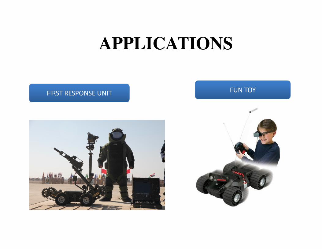
APPLICATIONS
FIRST RESPONSE UNIT FUN TOY

ROBOTIC SOLDIERROBOTIC SOLDIER
Source: www.policemag.com Source: www.strangehorizons.com

DEMONSTRATIONDEMONSTRATION

THANK YOU