Multi-Level Learning in Hybrid Deliberative/Reactive Mobile Robot Architectural Software Systems
Upload
nguyenkietCategory
view
222download
0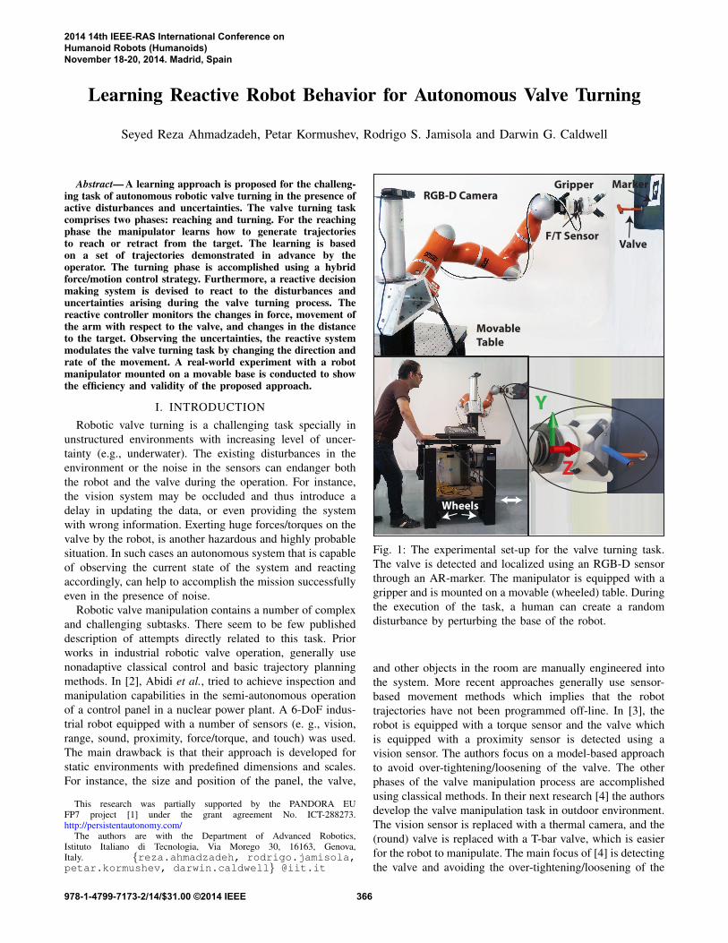
Learning Reactive Robot Behavior for Autonomous Valve Turning
Seyed Reza Ahmadzadeh, Petar Kormushev, Rodrigo S. Jamisola and Darwin G. Caldwell
Abstract— A learning approach is proposed for the challeng-ing task of autonomous robotic valve turning in the presence ofactive disturbances and uncertainties. The valve turning taskcomprises two phases: reaching and turning. For the reachingphase the manipulator learns how to generate trajectoriesto reach or retract from the target. The learning is basedon a set of trajectories demonstrated in advance by theoperator. The turning phase is accomplished using a hybridforce/motion control strategy. Furthermore, a reactive decisionmaking system is devised to react to the disturbances anduncertainties arising during the valve turning process. Thereactive controller monitors the changes in force, movement ofthe arm with respect to the valve, and changes in the distanceto the target. Observing the uncertainties, the reactive systemmodulates the valve turning task by changing the direction andrate of the movement. A real-world experiment with a robotmanipulator mounted on a movable base is conducted to showthe efficiency and validity of the proposed approach.
I. INTRODUCTION
Robotic valve turning is a challenging task specially inunstructured environments with increasing level of uncer-tainty (e.g., underwater). The existing disturbances in theenvironment or the noise in the sensors can endanger boththe robot and the valve during the operation. For instance,the vision system may be occluded and thus introduce adelay in updating the data, or even providing the systemwith wrong information. Exerting huge forces/torques on thevalve by the robot, is another hazardous and highly probablesituation. In such cases an autonomous system that is capableof observing the current state of the system and reactingaccordingly, can help to accomplish the mission successfullyeven in the presence of noise.
Robotic valve manipulation contains a number of complexand challenging subtasks. There seem to be few publisheddescription of attempts directly related to this task. Priorworks in industrial robotic valve operation, generally usenonadaptive classical control and basic trajectory planningmethods. In [2], Abidi et al., tried to achieve inspection andmanipulation capabilities in the semi-autonomous operationof a control panel in a nuclear power plant. A 6-DoF indus-trial robot equipped with a number of sensors (e. g., vision,range, sound, proximity, force/torque, and touch) was used.The main drawback is that their approach is developed forstatic environments with predefined dimensions and scales.For instance, the size and position of the panel, the valve,
This research was partially supported by the PANDORA EUFP7 project [1] under the grant agreement No. ICT-288273.http://persistentautonomy.com/
The authors are with the Department of Advanced Robotics,Istituto Italiano di Tecnologia, Via Morego 30, 16163, Genova,Italy. {reza.ahmadzadeh, rodrigo.jamisola,petar.kormushev, darwin.caldwell} @iit.it
RGB-D CameraGripper
Valve
Marker
Movable
Table
F/T Sensor
Wheels
Y
Z
Fig. 1: The experimental set-up for the valve turning task.The valve is detected and localized using an RGB-D sensorthrough an AR-marker. The manipulator is equipped with agripper and is mounted on a movable (wheeled) table. Duringthe execution of the task, a human can create a randomdisturbance by perturbing the base of the robot.
and other objects in the room are manually engineered intothe system. More recent approaches generally use sensor-based movement methods which implies that the robottrajectories have not been programmed off-line. In [3], therobot is equipped with a torque sensor and the valve whichis equipped with a proximity sensor is detected using avision sensor. The authors focus on a model-based approachto avoid over-tightening/loosening of the valve. The otherphases of the valve manipulation process are accomplishedusing classical methods. In their next research [4] the authorsdevelop the valve manipulation task in outdoor environment.The vision sensor is replaced with a thermal camera, and the(round) valve is replaced with a T-bar valve, which is easierfor the robot to manipulate. The main focus of [4] is detectingthe valve and avoiding the over-tightening/loosening of the
2014 14th IEEE-RAS International Conference onHumanoid Robots (Humanoids)November 18-20, 2014. Madrid, Spain
978-1-4799-7173-2/14/$31.00 ©2014 IEEE 366

valve in an early stage using a model-based technique.Other groups have also investigated valve turning. In [5]
a framework for valve turning is proposed using a dual-armarial manipulator system. The framework is built based onteleoperation and employs motion detection, voice controland joystick inputs. A user-guided manipulation frameworkis proposed in [6]. Although the planning algorithm generatesthe robot motions autonomously, the search process and theobject detection phase are accomplished by a human operatorand the result is passed to the robot. A dual-arm impedancehierarchical controller is devised in [7] that employs theupper body kinematics and dynamics of a humanoid robotfor reaching and turning a valve.
Compared to our previous research [8], [9], this workprovides the following three contributions: (i) in our previousresearch the turning phase was done by programming theturning motion into the robot. In this paper, on the otherhand, a force control strategy is proposed for handling theturning phase; (ii) similar to the previous research a ReactiveFuzzy Decision Maker (RFDM) system is designed in orderto react to external disturbances and sudden movements. Thereactive system in the previous work monitors only the rela-tive movement between the gripper and the valve, whereas,the new reactive system, also takes into consideration thedistance between the gripper and the valve, and the exertedforces to the end-effector besides the relative movement. Theacquired RFDM system shows more efficiency and bettersensitivity which results in a safer valve turning process;(iii) in our previous research an Optitrack system was usedwhich captures real-time 3D position and orientation of arigid body using a number of motion capture cameras and aset of markers. Although the Optitrack system is very precise,it cannot be used in outdoor environment. In this work, onthe other hand, an RGB-D sensor is used that provides theexperiment with a more realistic conditions.
All presented experiments in this work were conductedin a lab environment. The experimental set-up for all theexperiments is shown in Figure 1. Our future work includesinvestigating and accomplishing the autonomous roboticvalve manipulation in underwater environment which is oneof the most challenging tasks defined in the PANDORA [1]project.
II. METHODOLOGY
The valve turning task comprises two main phases: reach-ing and turning. First, the robot have to learn how to reachthe valve. Imitation learning approach which is designed spe-cially to learn trajectory-based tasks, is a promising choiceto learn the reaching skill [10]. In order to reproduce thereaching skill towards the target, the robot utilizes feedbackfrom the RGB-D sensor.
When the robot is able to reproduce the reaching skilla hybrid force/motion control strategy handles the turningphase. Hybrid force/motion control is a well-establishedmethod [11], [12], [13]. Using such hybrid strategy, theforce controller can maintain the contact between the valveand the gripper while the motion controller turns the valve.
Reaching PhaseImitation Learning
Turning PhaseForce Control
Reactive SystemFuzzy Decision Maker
Filter
RGBD Sensor
F/T Sensorforce
position
Human Expert Tuning (off-line)Optimization Algorithm
force
position [-1,1]
Membership Function Parameters
[-1,1]
Fig. 2: A high-level flow diagram illustrating the differentcomponents of the proposed approach.
The hybrid force/motion controller utilizes feedback from aForce/Torque (F/T) sensor mounted between the end-effectorand the gripper. Subsequent to the turning phase, the robotemploys the reaching skill in reverse to retract from the valve.
In order to develop an autonomous system, the robotneeds to deal with uncertainties. To emulate the uncertaintiesin our experiments, we manually apply disturbances to thesystem. The disturbances during the execution of the task aremonitored and handled by a Reactive Fuzzy Decision Maker(RFDM). Although such reactive system can be implementedusing a thresholding method, the fuzzy system is chosen.The reason is that the fuzzy system provides a continuousdecision surface and it infers from a set of human-definedlinguistic rules. The RFDM module, monitors the positionof the gripper and the valve together with the magnitudeof the forces and torques applied to the end-effector fromthe valve. Using this information, RFDM generates decisionsthat regulate the movements of the robot during the process.For example, RFDM halts the process when the magnitudeof the force increases due to an undesired movement. Inaddition, RFDM also controls the rate of the motion. Forinstance, when there is no external disturbance, the robotcan reach the valve faster.
As depicted in Figure 1 the experimental set-up for allthe conducted experiments consists of a 7-DoF KUKA-LWR manipulator mounted on a movable (wheeled) table,a (T-bar shaped) mock-up valve mounted on the wall inthe robot’s workspace, a gripper designed for grasping andturning the valve, an ATI Mini45 Force/Torque (F/T) sensorwhich is sandwiched between the gripper and the robots end-effector, and an ASUS Xtion RGB-D sensor for detecting andlocalizing the valve.
Figure 2 illustrates a flow diagram of the proposed ap-proach. The RGB-D sensor detects the pose of the valvewhich is used by the reaching module and RFDM. TheF/T sensor monitors the force/torque applied to the gripper,which is used by the turning module and RFDM. Observingthe inputs provided by the sensors, RFDM generates properdecisions in order to modulate the behavior of the robotduring the process. The RFDM system is tuned by collectingdata from a human expert using optimization techniques.
III. IMITATION LEARNING
Imitation learning enables manipulators to learn and re-produce trajectory-based skills from a set of demonstra-
367

tions [10]. The demonstrations are provided either by tele-operation or through kinesthetic teaching. One of the mostwidely-used representations for trajectory-based skills is Dy-namical Movement Primitives (DMP) [14]. DMP allows tolearn a compact representation of the reaching skill using therecorded demonstrations. In this paper, we use the extendedDMP approach proposed in [15] which also encapsulatesvariation and correlation information of the demonstratedskill as a mixture of dynamical systems. In order to reach atarget, in this approach a set of virtual attractors is utilized.The influence of these attractors is smoothly switched alongthe movement on a time basis. A proportional-derivativecontroller is used to move the end-effector towards thetarget. In contrast to the original DMP, a full stiffnessmatrix associated with each primitives is considered. Thisallows to capture the variability and correlation informationalong the movement. The set of attractors is learned throughweighted least-square regression, by using the residual errorsas covariance information to estimate stiffness gain matrices.
During the demonstration phase, multiple desired trajec-tories are demonstrated by a human operator through kines-thetic teaching. Each demonstration m ∈ {1, . . . ,M} consistsof a set of Tm positions x, velocities x, and accelerations x, ofthe end-effector in Cartesian space where x ∈ R3. A datasetis formed by concatenating the P = ∑
Mm=1 Tm data points. A
desired acceleration is computed based on a mixture of Lproportional-derivative systems as follows:
ˆx =L
∑i=1
hi(t)[KPi (µ
xi − x)− kvx], (1)
where ˆx is the desired acceleration, KPi are the stiffness
matrices, µxi are the centers of the attractors in Cartesian
space, hi(t) are the weighting functions, and kv is thederivative gain.
During the demonstration phase, the trajectories arerecorded independent of the explicit time. Instead, in orderto create an implicit time-dependency, t = −ln(s)/α , acanonical system is defined as follows:
s =−αs (2)
where s is the decay term initialized by s = 1 that mono-tonically converges to 0. Furthermore, a set of Gaussianbasis functions are defined as N (µT
i ,ΣTi ) in time space,
where the centers µTi are equally distributed in time and the
variance parameters ΣTi are set to a constant value inversely
proportional to the number of states. α is a fixed value whichdepends on the duration of the demonstrations.
By determining the weighting functions hi(t) through thedecay term s, the system sequentially converges to the setof attractors. Stiffness matrices KP
i and the centers µxi are
learned from the observed data using weighted least-squareregression. In the reproduction phase the system uses thelearned weights and set of attractors to reproduce a trajectoryto reach the target.
The recorded set of demonstrations is depicted as blackcurves in Figure 3. Following the described approach, the
system learns a set of attractors which can be seen in the2D plots in Figures 3a and 4a as blue ellipsoids. Usingthe learned set of attractors the robot is able to reproducea new trajectory from an arbitrary initial position towardsthe target. Each red trajectory in Figures 3 and 4 illustratesa reproduction. In both figures the goal, (the valve in ourexperiments), is shown in yellow. A snapshot of the reachingskill reproduced by the robot is shown in Figure 5.
In this paper, we introduce a new capability based on theimplicit timing: a reversible behavior of the system. Thisnew capability enables the robot to perform the following:(i) reactive behavior by switching the direction of the move-ment towards the target or away from it; (ii) after the task isfinished the robot uses this capability to retract the arm. Theadvantage of the presented capability is that by learning justthe reaching skill the robot is capable of reproducing multiplebehaviors including reaching and retracting, and switchingbetween them. This can be achieved by changing the timingequation from t =−ln(s)/α to t = t f inal + ln(s)/α .
Figure 4 illustrates a reproduction from an arbitrary initialposition towards the target. It can be seen that, in the middleof the movement the robot reverses the motion and movesbackwards. It has to be commented that, by executing thereverse motion, the robot goes back to the center of the firstattractor.
IV. FORCE/MOTION CONTROL STRATEGY
Once the robot learns the reaching skill, the turning phasebegins. In this phase, the goal of the robot is to turn the valve(by 180◦ from its initial configuration) while maintaining theposition of the gripper. To control the forces and torquesapplied to the end-effector, a hybrid force/motion controlapproach is used [11], [12], [13]. Hybrid force/motion con-troller is preferred to be used in this application becauseduring the turning phase a zero force controller can reducethe undesired forces and torques.
The proposed hybrid strategy is designed for 6-axes fullspace control. Forces and torques are controlled in the 5-axes while motion is controlled around the z-axis in order toturn the valve. The assigned coordinate system is depictedin Figure 1 which is set with respect to the initial pose ofthe gripper. The z-axis (surge and roll) is normal to the end-effector’s palm. The y-axis (sway and pitch) is perpendicularto the z-axis and pointing sideways. And the x-axis (heaveand yaw) is perpendicular to the z− y plane [16]. A desirednormal force is set along the z-axis in order to maintain thegripper in contact with the valve. Zero forces and torques arespecified along the x- and y-axes. The zero desired values ofthe forces and torques are designed to lessen the reactionaryforces and torques along (around) the axes during the valveturning process.
The hybrid force/motion controller is suitable for au-tonomous mobile manipulation [17]. In underwater environ-ment the valve turning task is more difficult due to the highlyunstructured and uncertain environment. Also, the valve canbe rusty and sensitive to high forces/torques.
We specify the forces and torques as follows:
368

−0.1 0 0.1 0.2 0.3 0.4 0.5 0.6 0.7 0.8
−0.2
−0.1
0
0.1
0.2
0.3
Y (m)
Z (
m)
Initial positions for reproduction
Target (the valve)
Initial positions for demonstration
(a) Trajectories and learned attractors in 2D plane.
−0.6
−0.4
−0.2
0
00.1
0.20.3
0.40.5
0.60.7
−0.2
−0.1
0
0.1
0.2
X (m)Y (m)
Z (
m)
Target (the valve)
Initial positionfor demonstration
Initial positionfor reproduction
(b) Trajectories in 3D space.
Fig. 3: The recorded trajectories that form the set of demon-strations (black), and the reproduced trajectory from an arbi-trary initial position (red) towards the target are illustrated.The blue ellipses show the attractors and the yellow squareshows the target (the valve).
Fcon = Fdes +kp(Fdes−Fact)
Tcon = Tdes +kp(Tdes−Tact)(3)
where F and T denote forces and torques respectively, andsubscripts des, act, and con denote the desired, actual, andcontrol parameters respectively. In the following sections,some experimental results are explained.
A. Valve Turning with Stationary Base
In the first set of experiments the base of the robotremained stationary during the valve turning task. So noexternal disturbances are applied to the valve or the gripper.In this case, to ensure proper contact between the valve andthe gripper during the turning phase a 20 N force alongthe z-axis is applied, Fz
des = 20 N. The other desired forcesand torques are set to zero Fx
des = Fydes = T x
des = T ydes = 0.
The desired roll angle is specified to be 180◦ clockwisewith respect to the current orientation of the end-effector.The duration of turning is set to 10s. The joint angledisplacements through the valve turning execution are shownin Figure 6, where the last joint moved from −90◦ to 90◦
−0.1 0 0.1 0.2 0.3 0.4 0.5 0.6 0.7 0.8
−0.2
−0.1
0
0.1
0.2
0.3
Y (m)
Z (
m)
Target (the valve)
Initial positionfor reproduction
final positionfor reproduction
(a) Trajectories and learned attractors in 2D plane.
−0.6
−0.4
−0.2
0
00.1
0.20.3
0.40.5
0.60.7
−0.2
−0.1
0
0.1
0.2
X (m)Y (m)
Z (
m)
final positionfor reproduction
initial positionfor reproduction
(b) Trajectories in 3D space.
Fig. 4: The recorded trajectories that form the set of demon-strations (black), and the reproduced trajectory from an arbi-trary initial position (red) are illustrated. The robot retractsfrom the middle of the path by receiving a command fromRFDM.
angle, while the rest of the joint angles move slightly in orderto dissipate the forces generated at the end-effector duringthe execution of the task.
It can be seen in the graphs that the first 5s of the operationis used for the gripper to make contact with the valve andthen dissipate the impact force. From 5s to 15s, the valveis turned by the motion controller and the generated forcesand torques at the end-effector are recorded. Figure 7 (topfigure) shows that the force along the z-axis is maintained at+20 N right after the impact forces have been dissipated. Thecontroller can maintain the magnitude of the force before,during, and after the valve turning successfully.
The exertion of the necessary torque to turn the valve andthe required force to maintain the contact between the valveand the gripper, generates residual forces and torques at theend-effector. In order to dissipate these reaction forces alongthe x- and y-axes, a set of forces in range −5 to +5 N aregenerated. During the turning phase until the 20s of the task,the z-axis torque averaged at around +1 Nm. This is shownin Figure 8 (top figure).
On the other hand, the torque around x-axis is maintained
369

Fig. 5: The robot reaching the valve during the reproductionphase.
0 5 10 15 20−100
−80
−60
−40
−20
0
20
40
60
80
100
Time (s)
Angles (deg)
Joint Angles
Joint 1
Joint 2
Joint 3
Joint 4
Joint 5
Joint 6
Joint 7
Fig. 6: Joint angles during the valve turning task withstationary base.
at −0.5 Nm at the start of the contact until the end of theturning phase, and then decreased to 0 Nm by the end ofthe task. The torque around the y-axis moved from its initialtorque, (after impact that is around −0.5 Nm) to −1 Nm inan attempt to dissipate the residual torques. However, due tothe physical limitation of the valve, (i.e., the gripper has aslot along the y-axis), it cannot create the necessary torque-resistance in order to dissipate the residual torque.
B. Valve Turning with Moving Base
In the next set of experiments the base of the manipulator,that is mounted on a wheeled table, is moved manually tocreate a disturbance during the turning task. These oscilla-tory disturbances simulate the dynamics of currents in theunderwater environment. In this experiment, the duration ofthe valve turning process is set to 30s to give enough time tothe operator to disturb the manipulator. The recorded forceand torque data during the valve turning with perturbed baseare shown in bottom sub-figures in Figures 7 and 8. Theperturbation is generated from 3s up to 33s of the overalltime.
V. LEARNING OF REACTIVE BEHAVIOR
In robotic valve turning in the real world, a suddenmovement of the arm can endanger both the valve and themanipulator. Also, if the robot exerts huge and uncontrolledamount of force/torque during the turning phase, it may break
0 5 10 15 20 25 30 35−10
−5
0
5
10
15
20
25
30
35
40
45
Time (s)
Force (N)
Force Feedback with Moving Base
Force X
Force Y
Force Z
0 2 4 6 8 10 12 14 16 18 20−10
−5
0
5
10
15
20
25
30
Time (s)
Force (N)
Force Feedback with Stationary Base
Force X
Force Y
Force Z
Fig. 7: End-effector forces during the valve turning task.
the valve off. In order to prevent such behaviors and devel-oping a more autonomous and reliable system, a reactivedecision maker system is designed. This system, which isa Reactive Fuzzy Decision Maker (RFDM), evaluates thedynamic behavior of the system and regulates the robot’smovements reactively.
We chose fuzzy systems because they are based on lin-guistic rules and the parameters that specify the membershipfunctions have clear physical meanings. Also, there aremethods to choose good initial values for the parameters ofa fuzzy system [18].
The RFDM system in our previous research [8], monitorsthe relative movement between the valve and the end-effectorand generates decisions according to the defined linguisticrules. One of the drawbacks of the previous reactive system isthat, it is independent of the distance between the gripper andthe valve. This means that despite the distance between thegripper and the valve, the robot shows identical behaviors.The proposed RFDM in this paper, on the other hand,comprises two more inputs. One is the distance betweenthe gripper and the valve. This extra information givesthe RFDM the capability to behave more adaptively. Forinstance, when the gripper is about to grasp the valve, thenew RFDM generates more watchful decisions and increasesthe sensitivity of the robot’s movements with respect tothe disturbances. The other input is the force/torque valuesapplied to the gripper and reacts to the uncertainties. For
370

0 5 10 15 20 25 30 35−1.5
−1
−0.5
0
0.5
1
1.5
Time (s)
Torque (Nm)
Torque Feedback with Moving Base
Torque XTorque YTorque Z
0 2 4 6 8 10 12 14 16 18 20−1.5
−1
−0.5
0
0. 5
1
1. 5
Time (s)
Torque (Nm)
Torque Feedback with Stationary Base
Torque XTorque YTorque Z
Fig. 8: End-effector torques during the valve turning task.
instance, RFDM retracts the arm when it observes a suddenincrease in force/torque during the turning phase.
A. Design of the Fuzzy System
The proposed fuzzy system comprises three inputs: a) thedistance between the gripper and the valve (the norm of thedistance vector); and b) the relative movement between thevalve and the gripper (in x− y plane); c) the forces andtorques applied to the valve from the gripper.
All the inputs are first normalized in range [0,1] and thenare sent to the RFDM system. The third input is providedby the F/T sensor which has a sampling interval equal to1 ms. The output of the sensor consists of three force andthree torque elements. In this case, the torque is multipliedby a factor to be numerically comparable to the value of theforce. The normalizing equation is as follows:
γ =‖F‖+β‖T‖
Fmax(4)
where γ ∈ [0,1], β = 10 is a constant factor used to level-offthe range of values between the forces and the torques, andFmax = 30 N is set as the maximum threshold.
Monitoring the relative movement between the valve andthe gripper, the system can detect oscillations with differentamplitudes and frequencies. For instance, if the end-effectoris reaching the valve, and the system senses an oscillationwith say Medium amplitude the fuzzy system reacts tothat by halting the arm. To simulate such behavior in the
experiments, the operator manually moves the table of therobot back and forth. Moreover, considering the distancebetween the gripper and the valve, the system can change itsbehavior adaptively. For example, if the gripper is Far fromthe valve, even in the presence of a disturbance, the robot stillmoves towards the valve. On the other hand, if the gripperis in the vicinity of the valve the robot reacts to smalleroscillations and waits or even retracts the arm. Furthermore,measuring the force/torque magnitudes applied to the gripper,generated by colliding either to the valve or other objects,the system reacts according to the defined rules.
The output of the RFDM system is the reactive decisionwhich is a real number in range [−1,1]. The sign of theoutput specifies the direction of the movement (i.e., + forgoing forward and − for going backward). For instance, −1means to retract with 100% speed, 0 means to stop, and 1means to approach with 100% speed. Therefore, the RFDMsystem not only decides the direction of the movement, butalso specifies the rate of the movement.
In order to design the fuzzy system, we consider theinputs to be u = [u1,u2,u3]
T and the output as r. Firstly,Ni(i = 1,2,3) fuzzy sets, A1
i ,A2i , ...,A
Nii , are defined in range
[0,1], which are normal, consistent, and complete with Gaus-sian membership functions µA1
i,µA2
i, ...,µ
ANii
. Then, we formNrule =N1×N2×N3 (3×4×3= 36) fuzzy IF−T HEN rulesas follows:
IF u1 is Ai11 and u2 is Ai2
2 and u3 is Ai33 T HEN y is Bi1i2i3
(5)Moreover, 7 constant membership function in range [−1,1]
are set for the output. Finally, the TSK fuzzy system is con-structed using product inference engine, singleton fuzzifier,and center average defuzzifier [18]:
r =∑
N1i1=1 ∑
N2i2=1 ∑
N3i3=1 yi1i2i3 µ
i1A1(u1)µ
i2A2(u2)µ
i3A3(u3)
∑N1i1=1 ∑
N2i2=1 ∑
N3i3=1 µ
i1A1(u1)µ
i2A2(u2)µ
i3A3(u3)
(6)
Since the fuzzy sets are complete, the fuzzy system iswell-defined and its denominator is always non-zero. Thedesigned fuzzy system cannot be illustrated in a single 3Dplot because it consists of three inputs and one output. Weplotted the fuzzy surface for input variables u2 and u3 overa single value of the variable u1. So each surface in Figure 9is related to a fixed value of u1. It can be seen from Figure 9that RFDM shows more sensitive and cautious behaviors asthe distance to the valve decreases.
B. Tuning the Fuzzy System
In order to tune the parameters of the devised fuzzysystem, the subconscious knowledge of a human expert isderived. In this case, the human expert knows what to dobut cannot express exactly in words how to do it. In order toextract the subconscious knowledge of the human expert, atutor simulates the effect of the disturbances (e.g., underwatercurrents) by moving the wheeled table, while the robottries to reach and turn the valve. Simultaneously, using a
371
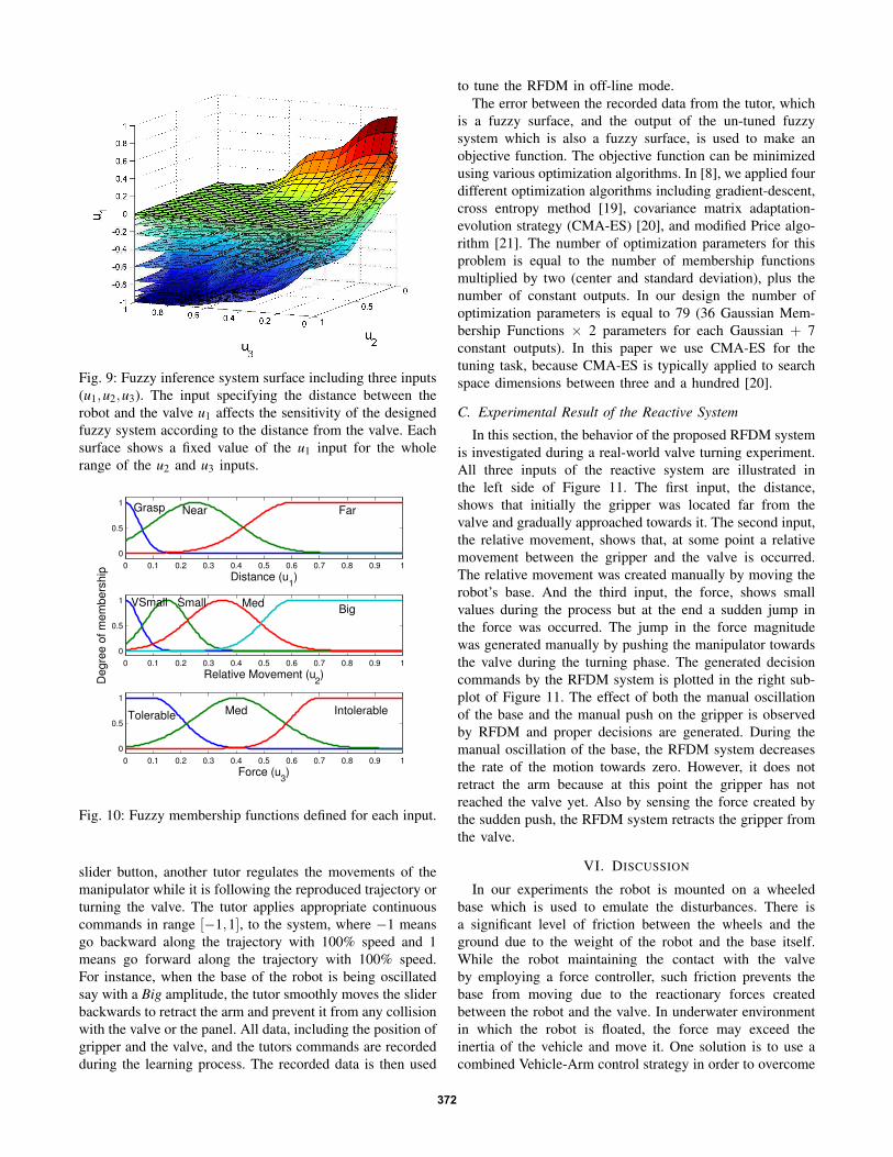
Fig. 9: Fuzzy inference system surface including three inputs(u1,u2,u3). The input specifying the distance between therobot and the valve u1 affects the sensitivity of the designedfuzzy system according to the distance from the valve. Eachsurface shows a fixed value of the u1 input for the wholerange of the u2 and u3 inputs.
0 0.1 0.2 0.3 0.4 0.5 0.6 0.7 0.8 0.9 1
0
0.5
1
Distance (u1)
Grasp Near Far
0 0.1 0.2 0.3 0.4 0.5 0.6 0.7 0.8 0.9 1
0
0.5
1
Relative Movement (u2)
Degre
e o
f m
em
bers
hip
VSmall Small MedBig
0 0.1 0.2 0.3 0.4 0.5 0.6 0.7 0.8 0.9 1
0
0.5
1
Force (u3)
Tolerable Med Intolerable
Fig. 10: Fuzzy membership functions defined for each input.
slider button, another tutor regulates the movements of themanipulator while it is following the reproduced trajectory orturning the valve. The tutor applies appropriate continuouscommands in range [−1,1], to the system, where −1 meansgo backward along the trajectory with 100% speed and 1means go forward along the trajectory with 100% speed.For instance, when the base of the robot is being oscillatedsay with a Big amplitude, the tutor smoothly moves the sliderbackwards to retract the arm and prevent it from any collisionwith the valve or the panel. All data, including the position ofgripper and the valve, and the tutors commands are recordedduring the learning process. The recorded data is then used
to tune the RFDM in off-line mode.The error between the recorded data from the tutor, which
is a fuzzy surface, and the output of the un-tuned fuzzysystem which is also a fuzzy surface, is used to make anobjective function. The objective function can be minimizedusing various optimization algorithms. In [8], we applied fourdifferent optimization algorithms including gradient-descent,cross entropy method [19], covariance matrix adaptation-evolution strategy (CMA-ES) [20], and modified Price algo-rithm [21]. The number of optimization parameters for thisproblem is equal to the number of membership functionsmultiplied by two (center and standard deviation), plus thenumber of constant outputs. In our design the number ofoptimization parameters is equal to 79 (36 Gaussian Mem-bership Functions × 2 parameters for each Gaussian + 7constant outputs). In this paper we use CMA-ES for thetuning task, because CMA-ES is typically applied to searchspace dimensions between three and a hundred [20].
C. Experimental Result of the Reactive System
In this section, the behavior of the proposed RFDM systemis investigated during a real-world valve turning experiment.All three inputs of the reactive system are illustrated inthe left side of Figure 11. The first input, the distance,shows that initially the gripper was located far from thevalve and gradually approached towards it. The second input,the relative movement, shows that, at some point a relativemovement between the gripper and the valve is occurred.The relative movement was created manually by moving therobot’s base. And the third input, the force, shows smallvalues during the process but at the end a sudden jump inthe force was occurred. The jump in the force magnitudewas generated manually by pushing the manipulator towardsthe valve during the turning phase. The generated decisioncommands by the RFDM system is plotted in the right sub-plot of Figure 11. The effect of both the manual oscillationof the base and the manual push on the gripper is observedby RFDM and proper decisions are generated. During themanual oscillation of the base, the RFDM system decreasesthe rate of the motion towards zero. However, it does notretract the arm because at this point the gripper has notreached the valve yet. Also by sensing the force created bythe sudden push, the RFDM system retracts the gripper fromthe valve.
VI. DISCUSSION
In our experiments the robot is mounted on a wheeledbase which is used to emulate the disturbances. There isa significant level of friction between the wheels and theground due to the weight of the robot and the base itself.While the robot maintaining the contact with the valveby employing a force controller, such friction prevents thebase from moving due to the reactionary forces createdbetween the robot and the valve. In underwater environmentin which the robot is floated, the force may exceed theinertia of the vehicle and move it. One solution is to use acombined Vehicle-Arm control strategy in order to overcome
372
0 100 200 3000
0.5
1D
ista
nce
0 100 200 3000
0.2
0.4
Rel
ativ
e M
ovem
ent
0 100 200 3000
0.5
1
For
ce
Time (s)0 100 200 300
−0.4
−0.2
0
0.2
0.4
0.6
0.8
1
reac
tive
com
man
d
Time (s)
Fig. 11: The recorded set of inputs and the generated decisioncommands by the RFDM system during a real-world valveturning experiment.
this unwanted behavior. The controller generates more thrustto keep the position of the robot while keeping the contactbetween the arm and the valve.
Employing the hybrid force/motion controller, the robot’sreaction to a stuck valve can happen simultaneously accord-ing to three different scenarios. First, due to the desiredforce specified normal to the valve, the gripper will continueto exert a normal force to maintain contact. Second, dueto the desired zero forces and torques along (and around)the x- and y-axes, the gripper will automatically adjust itsgripping configuration such that the reactionary forces andtorques along (and around) these axes are lessened. Lastly,in applying the required torque to turn the valve, the gripperwill apply the maximum possible torque around the z-axis,until the motors get saturated.
VII. CONCLUSIONS
We have proposed a learning method for reactive robotbehavior to deal with the challenging task of autonomousvalve turning. The autonomous valve turning consists oftwo main phases: reaching and turning. Imitation learningis used to learn and reproduce the reaching phase. A hybridforce/motion controller is devised to accomplish the turningphase. In order to increase the autonomy of the system areactive fuzzy decision maker is developed. This moduleevaluates the dynamic behavior of the system and modulatesthe robots movements reactively. The validity and perfor-mance of our approach is demonstrated through a real-worldvalve turning experiment.
REFERENCES
[1] D. M. Lane, F. Maurelli, P. Kormushev, M. Carreras, M. Fox, andK. Kyriakopoulos, “Persistent autonomy: the challenges of the PAN-DORA project,” Proceedings of IFAC MCMC, 2012.
[2] M. A. Abidi, R. O. Eason, and R. C. Gonzalez, “Autonomous roboticinspection and manipulation using multisensor feedback,” Computer,vol. 24, no. 4, pp. 17–31, 1991.
[3] D. A. Anisi, E. Persson, and C. Heyer, “Real-world demonstration ofsensor-based robotic automation in oil & gas facilities,” in IntelligentRobots and Systems (IROS), 2011 IEEE/RSJ International Conferenceon. IEEE, 2011, pp. 235–240.
[4] D. A. Anisi, C. Skourup, and A. Petrochemicals, “A step-wise ap-proach to oil and gas robotics,” in IFAC Workshop on AutomaticControl in Offshore Oil and Gas Production, Trondheim, Norway,vol. 31, 2012.
[5] M. Orsag, C. Korpela, S. Bogdan, and P. Oh, “Valve turning using adual-arm aerial manipulator,” in Unmanned Aircraft Systems (ICUAS),2014 International Conference on. IEEE, 2014, pp. 836–841.
[6] N. Alunni, C. Phillips-Grafftin, H. B. Suay, D. Lofaro, D. Berenson,S. Chernova, R. W. Lindeman, and P. Oh, “Toward a user-guidedmanipulation framework for high-dof robots with limited communica-tion,” in Technologies for Practical Robot Applications (TePRA), 2013IEEE International Conference on. IEEE, 2013, pp. 1–6.
[7] A. Ajoudani, J. Lee, A. Rocchi, M. Ferrati, E. M. Hoffman, A. Settimi,N. G. Tsagarakis, D. G. Caldwell, and A. Bicchi, “Dual arm impedancecontrol with a compliant humanoid: Application to a valve turningtask.”
[8] S. R. Ahmadzadeh, P. Kormushev, and D. G. Caldwell, “Autonomousrobotic valve turning: A hierarchical learning approach,” in Roboticsand Automation (ICRA), 2013 IEEE International Conference on.IEEE, 2013, pp. 4614–4619.
[9] A. Carrera, S. Ahmadzadeh, A. Ajoudani, P. Kormushev, M. Carreras,and D. Caldwell, “Towards autonomous robotic valve turning,” Cy-bernetics and Information Technologies, vol. 12, no. 3, 2012.
[10] S. Schaal, A. Ijspeert, and A. Billard, “Computational approaches tomotor learning by imitation,” Philosophical Transactions of the RoyalSociety of London. Series B: Biological Sciences, vol. 358, no. 1431,pp. 537–547, 2003.
[11] M. H. Raibert and J. J. Craig, “Hybrid position/force control of ma-nipulators,” Journal of Dynamic Systems, Measurement, and Control,vol. 103, no. 2, pp. 126–133, 1981.
[12] O. Khatib, “A unified approach for motion and force control ofrobot manipulators: The operational space formulation,” Robotics andAutomation, IEEE Journal of, vol. 3, no. 1, pp. 43–53, 1987.
[13] T. Yoshikawa and X.-Z. Zheng, “Coordinated dynamic hybrid po-sition/force control for multiple robot manipulators handling oneconstrained object,” The International Journal of Robotics Research,vol. 12, no. 3, pp. 219–230, 1993.
[14] A. J. Ijspeert, J. Nakanishi, H. Hoffmann, P. Pastor, and S. Schaal,“Dynamical movement primitives: learning attractor models for motorbehaviors,” Neural computation, vol. 25, no. 2, pp. 328–373, 2013.
[15] P. Kormushev, S. Calinon, and D. G. Caldwell, “Imitation learning ofpositional and force skills demonstrated via kinesthetic teaching andhaptic input,” Advanced Robotics, vol. 25, no. 5, pp. 581–603, 2011.
[16] S. N. Das and S. K. Das, “Determination of coupled sway, roll,and yaw motions of a floating body in regular waves,” InternationalJournal of Mathematics and Mathematical Sciences, vol. 2004, no. 41,pp. 2181–2197, 2004.
[17] R. S. Jamisola, D. N. Oetomo, M. H. Ang, O. Khatib, T. M. Lim,and S. Y. Lim, “Compliant motion using a mobile manipulator: anoperational space formulation approach to aircraft canopy polishing,”Advanced Robotics, vol. 19, no. 5, pp. 613–634, 2005.
[18] L. Wang, A Course on Fuzzy Systems. Prentice-Hall press, USA,1999.
[19] R. Y. Rubinstein and D. P. Kroese, The cross-entropy method: a unifiedapproach to combinatorial optimization, Monte-Carlo simulation andmachine learning. Springer, 2004.
[20] N. Hansen, “The cma evolution strategy: a comparing review,” inTowards a new evolutionary computation. Springer, 2006, pp. 75–102.
[21] P. Brachetti, M. D. F. Ciccoli, G. Di Pillo, and S. Lucidi, “A newversion of the price’s algorithm for global optimization,” Journal ofGlobal Optimization, vol. 10, no. 2, pp. 165–184, 1997.
373
![7 reactive and behavior-based paradigm.pptftang/courses/CS521/notes/reactive architecture.pdfMicrosoft PowerPoint - 7 reactive and behavior-based paradigm.ppt [Compatibility Mode]](https://static.fdocuments.us/doc/165x107/5f0c5b777e708231d4350047/7-reactive-and-behavior-based-ftangcoursescs521notesreactive-architecturepdf.jpg)