AUTOMATION METHODS FOR FORMING AND RECTIFYING …
8
AUTOMATION METHODS FOR FORMING AND RECTIFYING STIFFENED PARTS WITH ROLLING MACHINES A.Ye. Pashkov, Doctor of technical sciences, Professor of the Department of Machinery and Automation of Mechanical Irkutsk National Research Technical University A.A. Makaruk, Candidate of Engineering Sciences Irkutsk National Research Technical University N.V. Minaev, research assistant Irkutsk National Research Technical University To improve the capabilities of forming and rectifying stiffened parts, rolling as one of the implemented methods of local plastic deformation has been examined. The tools for edge and sheet rolling have been described. The methods of process automation have been developed. Key words: rolling, rolling machine, rectification by rolling, forming, stiffened parts, sheet, edge, twisting, biaxial bending. In the aviation industry, the application of new high-strength and low-ductility alloys caused the need for developing the method of forming and rectifying machined parts made from these materials. The parts under examination are longerons, beams, frames, ribs, etc. (see Figure 1, a). In most cases, they are produced by milling from thermally stiffened aluminum alloy plates and profiles. Figure 1 shows thick-wall beams. To increase the stiffness of their structures, the additional elements are required – longitudinal and lateral edges which enable formation of pockets in the parts. Fig. 1 Typical milled parts of the basic structure (а) and their cross-sections (b) The longitudinal edges can be off parallel with each other (“beveled” edges). Their number may range from 2 to 4. As a result, the cross-sections can be T-, U-, I-shaped, etc. The typical cross-sections are shown in Figure 1, b. Irkutsk Aviation Plant (branch of IRKUT Corporation), sets high accuracy requirements to the aircraft parts (the maximum acceptable deviation from the desired shape is ±0.15mm). а b e-ISSN : 0975-4024 A.Ye. Pashkov et al. / International Journal of Engineering and Technology (IJET) p-ISSN : 2319-8613 Vol 7 No 6 Dec 2015-Jan 2016 2030
Transcript of AUTOMATION METHODS FOR FORMING AND RECTIFYING …
AUTOMATION METHODS FOR FORMING AND RECTIFYING
STIFFENED PARTS WITH ROLLING MACHINES
A.Ye. Pashkov, Doctor of technical sciences, Professor of the Department of Machinery and Automation of Mechanical
Irkutsk National Research Technical University
A.A. Makaruk, Candidate of Engineering Sciences
Irkutsk National Research Technical University
N.V. Minaev, research assistant
Irkutsk National Research Technical University
To improve the capabilities of forming and rectifying stiffened parts, rolling as one of the implemented methods of local plastic deformation has been examined. The tools for edge and sheet rolling have been described. The methods of process automation have been developed.
Key words: rolling, rolling machine, rectification by rolling, forming, stiffened parts, sheet, edge, twisting, biaxial bending.
In the aviation industry, the application of new high-strength and low-ductility alloys caused the need for developing the method of forming and rectifying machined parts made from these materials.
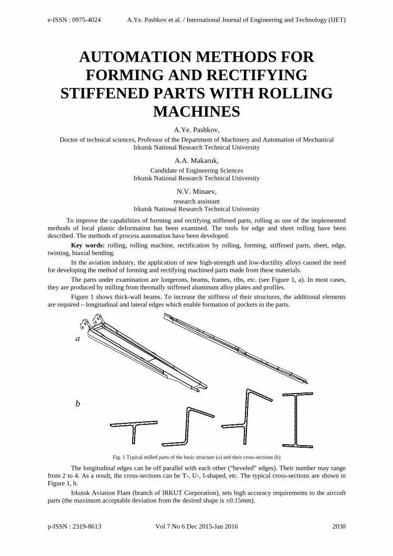
The parts under examination are longerons, beams, frames, ribs, etc. (see Figure 1, a). In most cases, they are produced by milling from thermally stiffened aluminum alloy plates and profiles.
Figure 1 shows thick-wall beams. To increase the stiffness of their structures, the additional elements are required – longitudinal and lateral edges which enable formation of pockets in the parts.
Fig. 1 Typical milled parts of the basic structure (а) and their cross-sections (b)
The longitudinal edges can be off parallel with each other (“beveled” edges). Their number may range from 2 to 4. As a result, the cross-sections can be T-, U-, I-shaped, etc. The typical cross-sections are shown in Figure 1, b.
Irkutsk Aviation Plant (branch of IRKUT Corporation), sets high accuracy requirements to the aircraft parts (the maximum acceptable deviation from the desired shape is ±0.15mm).
а
b
e-ISSN : 0975-4024 A.Ye. Pashkov et al. / International Journal of Engineering and Technology (IJET)
p-ISSN : 2319-8613 Vol 7 No 6 Dec 2015-Jan 2016 2030

The major problem which decreases the production efficiency is the distortion of the parts caused by the residual stress (biaxial bending or twisting of cross-sections) as shown in Figure 2.
Fig. 2 Deviations of stiffened parts
The above-mentioned features either limit the application of traditional rectification methods (e.g., pressure shaping and peen-forming), or we fail to achieve the desired result, the deviations are inacceptable, and the parts require refinishing.
The application of the low-ductility alloy 1933T is also a constraint because the forming of thin-wall parts made from this material can result in cracking.
We can improve the process capabilities by using the methods of local plastic deformation (e.g., rolling) [1].
The invention of the English wheel marked the beginning of using this method. The machine is shaped like a letter "C" (see Figure 4). At the ends of the C, there are two wheels – the rolling wheel and the anvil wheel. The tool is used for finishing metal sheets and forming compound curves by means of stretching the material and causing it to become thinner. The process is highly-skilled and labor-intensive. It is used in aircraft-, automobile-, and small vessel production industries.
Fig. 3 The English wheel
It is known that rolling is used in forming wing panels as a part of the combined method. In this process, forming by rolling is used to cause longitudinal elastic plastic deformations [3]. The method is based on the combination of deformations caused by longitudinal rolling and lateral peen-forming due to which we can achieve different shapes.
In machining panels, uniaxial bending and twisting are required. For this reason, only the edges of the parts require rolling (see Figure 4, а). In machining parts with asymmetric cross-sections, both edge rolling and sheet rolling are required (see Figure 4, b).
e-ISSN : 0975-4024 A.Ye. Pashkov et al. / International Journal of Engineering and Technology (IJET)
p-ISSN : 2319-8613 Vol 7 No 6 Dec 2015-Jan 2016 2031

a b
Figure 4 Forming (а) and rectifying (b) with a rolling machine
Based on the plane characteristics, the stiffened parts are referred to thin-wall beams whose extension in all three planes can be expressed by different orders of values: the thickness is small as compared to the size of the cross section, and they are both small as compared to the length [4].
While calculating the rolling deformations, we should take into account the specific features of thin-wall beams: the distribution of bending deformations and stresses is governed by the sectorial area principle rather than by the flat cross-section hypothesis. The axial forces applied to its face cause the beam to bend and twist. For the part with an asymmetric cross-section, the bending is biaxial (see Figure 5).
Figure 5 Model of the deformed area
To determine the deflection, we must measure the deviations of the part in the checkpoints located in mutually perpendicular bending planes with specified steps.
The bend angle for a specific area is controlled with the coordinates of the checkpoints located in the extreme cross-sections l apart. Figure 6 shows the CMM-based deviation measurements for “Rim” used to determine the bend in XOY coordinate plane (deviations from the theoretical contour). The deviations in ZOY plane are measured in a similar way (planeness deviations).
e-ISSN : 0975-4024 A.Ye. Pashkov et al. / International Journal of Engineering and Technology (IJET)
p-ISSN : 2319-8613 Vol 7 No 6 Dec 2015-Jan 2016 2032

Figure 6 Deviation measurements for “Rim” in XOY plane
The areas to be rolled can be identified by means of CMM-based measurements. The deviation diagram for checkpoints along the part can help identify the arched areas with the maximum deviation. For these areas (see Figure 7), we can determine the average deviations from the checkpoints located in three cross-sections:
ср ⋯ / ; (1) ср ⋯ / ; (2)
where i is the number of the cross-section, N is the amount of checkpoints in the cross-section i with the coordinates in a desired bending plane.
Figure 7 Deviations of the area
The deflections in two planes of the area on a-basis can be calculated by the equations (Figure 8): ср ср ср /2; (3) ср ср ср /2. (4) The bend angle can be calculated by the equation (see Figure 7): / / . (5)
e-ISSN : 0975-4024 A.Ye. Pashkov et al. / International Journal of Engineering and Technology (IJET)
p-ISSN : 2319-8613 Vol 7 No 6 Dec 2015-Jan 2016 2033

Figure 8 Determination of deflections of the area
When calculating the longitudinal stretching forces required for achieving the desired shapes of the machined areas, both the standard geometric characteristics of cross-sections (the moment of inertia and gravity center coordinates) used to determine the curvature in two planes and the twisting behaviors of cross-sections (the sectorial moment of inertia and twist center coordinates) used in calculating the bend angle are required (Figure 9).
Figure 9 Centers of gravity and twisting of the asymmetric cross-sections
Unigraphics and Lira Soft can be applied in calculating geometric and twisting characteristics of the cross-sections.
The longitudinal stretching forces and their centers are calculated by the system of equations based on the simultaneous biaxial bending and twisting affected by the longitudinal forces acting on the cross-sections: ∙ ∙ ⋯ ∙ ∙ ; ∙ ∙ ⋯ ∙ ∙ ; (6) ∙ ∙ ⋯ ∙ / ∙ ;
where , ,.. are the longitudinal stretching forces from rolling acting on the cross-sections of the area; , , , ,.. , are the coordinates of the centers of the longitudinal stretching forces; is the sectorial area (the double area of the sector 1O AB in Figure 9), is the modulus of elasticity; is the modulus of shear; , are the axial moments of inertia of the cross-section; is the moment of inertia of the twisted
e-ISSN : 0975-4024 A.Ye. Pashkov et al. / International Journal of Engineering and Technology (IJET)
p-ISSN : 2319-8613 Vol 7 No 6 Dec 2015-Jan 2016 2034
cross-section; is the length of the deflection; is the distance between the cross-sections; is the constant of proportionality dependent on the mechanical properties of the material:
,
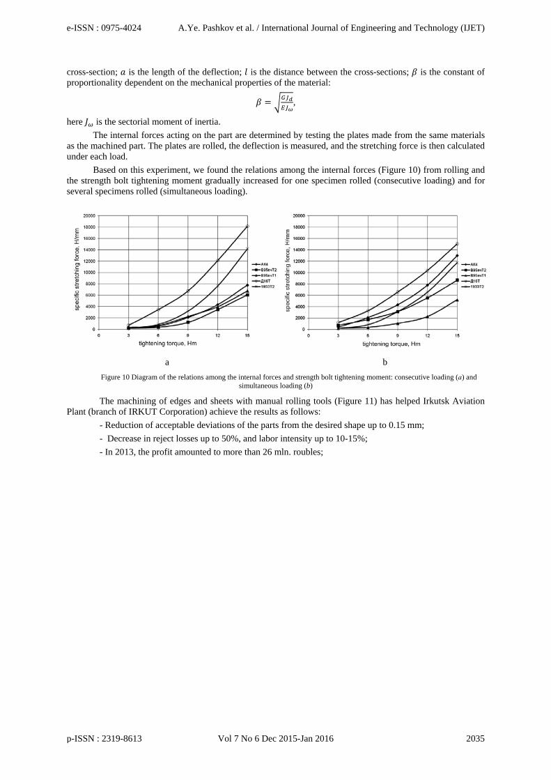
here is the sectorial moment of inertia. The internal forces acting on the part are determined by testing the plates made from the same materials
as the machined part. The plates are rolled, the deflection is measured, and the stretching force is then calculated under each load.
Based on this experiment, we found the relations among the internal forces (Figure 10) from rolling and the strength bolt tightening moment gradually increased for one specimen rolled (consecutive loading) and for several specimens rolled (simultaneous loading).
a b
Figure 10 Diagram of the relations among the internal forces and strength bolt tightening moment: consecutive loading (а) and simultaneous loading (b)
The machining of edges and sheets with manual rolling tools (Figure 11) has helped Irkutsk Aviation Plant (branch of IRKUT Corporation) achieve the results as follows:
- Reduction of acceptable deviations of the parts from the desired shape up to 0.15 mm; - Decrease in reject losses up to 50%, and labor intensity up to 10-15%; - In 2013, the profit amounted to more than 26 mln. roubles;
e-ISSN : 0975-4024 A.Ye. Pashkov et al. / International Journal of Engineering and Technology (IJET)
p-ISSN : 2319-8613 Vol 7 No 6 Dec 2015-Jan 2016 2035

Figure 11 Tools for edge rolling (а) and sheet rolling (b)
At present, the calculation software for technological parameters and multipurpose rolling units suitable for the machining of different parts is being developed.
The software includes two modules used for: 1. CAD-and CMM-based determinations of geometric and twisting characteristics of cross-sections and
components specified for causing (eliminating) deformations. 2. Calculations of rolling process parameters for causing (eliminating) specified deformations based on
the determination of desired stretching forces and the coordinates of their centers. The first software module performs the functions as follows: - Interactive marking of the machined areas; - Based on the measurements of the real part, tasking the initial deformations (two-plane deviations and
the bend angle) for the areas; - Initial data specification (geometric characteristics and desired deformations) for each machined area; - Based on the initial and desired deflections, calculating the deflections to be obtained (eliminated) in
two planes and the bend angle. The second software module performs the functions as follows: - Based on the specified deformations and geometric characteristics of the machined area, calculating
the value of stretching forces and their centers; - Calculating the technological parameters for rolling: the pressure of a wheel load hydraulic power
cylinder, the position of wheels when rolling each area; - Graphic and textual representation of strength factors and geometric characteristics of cross-sections. The rolling unit can be used for: 1. Machining the light parts (e.g., beams and profiles) by moving them along the rolling surface
towards the anchored in a required position self-tightening operating element; 2. Machining the large parts (e.g., panels) by moving the operating element adjusted to the wheel
rotation towards the part fixed on the bench. The development of software and multipurpose tooling units will exhibit a 1.5-2 fold increase in
production.
e-ISSN : 0975-4024 A.Ye. Pashkov et al. / International Journal of Engineering and Technology (IJET)
p-ISSN : 2319-8613 Vol 7 No 6 Dec 2015-Jan 2016 2036

References
[1] Pashkov A.Ye., Vikulova S.V., Makaruk A.A. Formoobrazovanie i pravka malozhestkikh detaley pri pomoshchi perenosnogo instrumenta [Forming and rectification of low stiffness parts with portable tools]. High Technologies in Machine Building: All-Russian Science and Technology Conference. Samara, SamGTU, 2009. P 156–159.
[2] https://en.wikipedia.org/wiki/English_wheel [3] Pashkov A.Ye., Plikhunov V.V., Rumyantsev Yu.S., Veprev A.A., Sergunov A.V. O sozdanii otraslevoy tekhnologii drobeudarnogo
formoobrazovaniya paneley [On the development of peen-forming methods for aircraft panels]. Aviation industry. Moscow: NIAT. 2009. No 2. P. 24-29.
[4] Vlasov V.Z. Tonkostennye uprugie sterzhni [Thin wall elastic beams]. Physics and Mathematics Literature Publishing House. Moscow. 1959. 574 p.
e-ISSN : 0975-4024 A.Ye. Pashkov et al. / International Journal of Engineering and Technology (IJET)
p-ISSN : 2319-8613 Vol 7 No 6 Dec 2015-Jan 2016 2037