AUTOMATIC ROOM LIGHT AND OTHER APPLIENCES … · This Project ―Automatic Room Light Controller...
15
www.ijcrt.org ©2018 IJCRT | Conference on Recent Innovations in Emerging Technology & Science, April 6- 7, 2018 | ISSN: 2320-2882 by JB Institute of Technology, Dehradun & IJCRT IJCRTRIETS033| International Journal of Creative Research Thoughts (IJCRT) www.ijcrt.org |Page 194 AUTOMATIC ROOM LIGHT AND OTHER APPLIENCES CONTROLLER WITH BIDIRECTIONAL VISITOR COUNTER (1)Mr.Rakesh Kumar,(2)Mr.Shubhashish Goswami (3)Mr.Digvijay Singh,(4) Mr.Upendra Bisht Dev Bhoomi Institute of Technology, Dehradun Abstract: Any organization building has cabins, rooms, and covered working areas which is connected electric energy for facility working environment, electric component of the energy used is spent in illuminating the interior of the building As the electricity costs rise, increasing effort has gone into minimizing the energy consumption of electric components installations. These are three basic directions of consumption of electricity: new more efficient equipment, utilization of improved lighting design practices (localized task lighting systems), improvements in lighting control systems to avoid energy waste for unoccupied and daylight hours or unnecessary. Automatically controlling the electricity in such a way that the lighting level is always accurately matched to the actual need allows to save on the energy costs and to improve the human comfort and efficiency. Such as Automatic Room Lighting and other equipment System are a microcontroller based project that automatically turn on or off the lights in a room. Establishing an integrated lighting control of microcontroller concept is a very important part of the lighting design process and other equipment which use only human presence. Electricity, being one of the most important resources, must be utilized carefully. The paper describes human often forget to switch off lights or other electric component (fan, AC, room heater) when we leave a room. By using this system, we can intentionally forget about the lights as the system will automatically take care of them the installations are realized according to a research project about the assessment of the impact of lighting control systems in electrical energy consumption and energy commitments. The two different control technologies are compared with respect to a third classroom without smart control, used as reference for evaluations. Experimental results suggested that the classroom electrical appliance monitor work was stable and reliable, having practical popularized value .In order to monitor the classroom electrical power usage and achieve low-carbon energy Introduction Of Project :- 1.1 Project Definition:- title is “Automatic Room Light Controller With Project Bidirectional Visitor Counter”. The objective of this project is to make a controller based model to count number of persons visiting particular room and accordingly light up the room. Here we can use sensor and can know present number of persons. In today’s world, there is a continuous need for automatic appliances. With the increase in standard of living, there is a sense of urgency for developing circuits that would ease the complexity of life. Also if at all one wants to know the number of people present in room soaps not to have congestion, this circuit proves to be helpful. This project "automatic room light controller with visitor counter using microcontroller" is a reliable circuit that takes over the task of persons/visitor in the room very accurately. When somebody enters into the room will be switched ON and when any one. The light in room will be only switched OFF until all the persons in the room go out. The total number of person inside the room also displayed on the seven segment displays. The microcontroller does the above job. it receives the signals from the sensors, and this signal is operated under the control of software which is stored in rom. Micron roller AT89S52 continuously monitor the infrared receivers, when any object pass through the IR rays falling on the receivers are obstructed this obstruction is sensed by the microcontroller.
Transcript of AUTOMATIC ROOM LIGHT AND OTHER APPLIENCES … · This Project ―Automatic Room Light Controller...

www.ijcrt.org ©2018 IJCRT | Conference on Recent Innovations in Emerging Technology & Science, April 6-7, 2018 | ISSN: 2320-2882 by JB Institute of Technology, Dehradun & IJCRT
IJCRTRIETS033| International Journal of Creative Research Thoughts (IJCRT) www.ijcrt.org |Page 194
AUTOMATIC ROOM LIGHT AND OTHER APPLIENCES CONTROLLER
WITH BIDIRECTIONAL VISITOR COUNTER
(1)Mr.Rakesh Kumar,(2)Mr.Shubhashish Goswami (3)Mr.Digvijay Singh,(4) Mr.Upendra Bisht
Dev Bhoomi Institute of Technology, Dehradun
Abstract:
Any organization building has cabins, rooms, and covered working areas which is connected electric energy for facility
working environment, electric component of the energy used is spent in illuminating the interior of the building As the
electricity costs rise, increasing effort has gone into minimizing the energy consumption of electric components installations. These are three basic directions of consumption of electricity: new more efficient equipment, utilization of improved lighting
design practices (localized task lighting systems), improvements in lighting control systems to avoid energy waste for
unoccupied and daylight hours or unnecessary. Automatically controlling the electricity in such a way that the lighting level is always accurately matched to the actual need allows to save on the energy costs and to improve the human comfort and
efficiency. Such as Automatic Room Lighting and other equipment System are a microcontroller based project that
automatically turn on or off the lights in a room. Establishing an integrated lighting control of microcontroller concept is a
very important part of the lighting design process and other equipment which use only human presence. Electricity, being one of the most important resources, must be utilized carefully. The paper describes human often forget to switch off lights or
other electric component (fan, AC, room heater) when we leave a room. By using this system, we can intentionally forget
about the lights as the system will automatically take care of them the installations are realized according to a research project about the assessment of the impact of lighting control systems in electrical energy consumption and energy commitments. The two different control technologies are compared with respect to a third classroom without smart control, used as
reference for evaluations. Experimental results suggested that the classroom electrical appliance monitor work was stable and
reliable, having practical popularized value .In order to monitor the classroom electrical power usage and achieve low-carbon energy
Introduction Of Project :-
1.1 Project Definition:-
title is “Automatic Room Light Controller With
Project
Bidirectional Visitor Counter”.
The objective of this project is to make a controller based model to count number of persons visiting particular
room and accordingly light up the room. Here we can use sensor and can know present number of persons.
In today’s world, there is a continuous need for automatic appliances. With the increase in standard of
living, there is a sense of urgency for developing circuits that would ease the complexity of life.
Also if at all one wants to know the number of people present in room soaps not to have congestion, this
circuit proves to be helpful.
This project "automatic room light controller with visitor counter using microcontroller"
is a reliable circuit that takes over the task of persons/visitor in the room very accurately. When somebody enters into the room will be switched ON and when any one. The light in room will be only switched OFF until all the persons in the
room go out. The total number of person inside the room also displayed on the seven segment displays.
The microcontroller does the above job. it receives the signals from the sensors, and this signal is operated under the control of software which is stored in rom.
Micron roller AT89S52 continuously monitor the infrared receivers, when any object pass through the IR rays falling on the receivers are obstructed this obstruction is sensed by the microcontroller.

www.ijcrt.org ©2018 IJCRT | Conference on Recent Innovations in Emerging Technology & Science, April 6-7, 2018 | ISSN: 2320-2882 by JB Institute of Technology, Dehradun & IJCRT
IJCRTRIETS033| International Journal of Creative Research Thoughts (IJCRT) www.ijcrt.org |Page 195
1.2Project Overview:-
This Project ―Automatic Room Light Controller with Visitor Counter using Microcontroller is a reliable circuit
that takes over the task of controlling the room lights as well us counting number of persons/ visitors in the room very
accurately. When somebody enters into the room then the counter is incremented by one and the light in the room will be switched ON and when any one leaves the room then the counter is decremented by one. The light will be only switched OFF
until all the persons in the room go out. The total number of persons inside the room is also displayed on the seven segment
displays.
The microcontroller does the above job. It receives the signals from the sensors, and this signal is operated under
the control of software which is stored in ROM. MicrocontrollerAT89S52 continuously monitor the Infrared Receivers,
When any object pass through the IR Receiver's then the IR Rays falling on the receiver are obstructed , this obstruction is sensed by the Microcontroller.
Blockdiagram:-
Block Diagram Description:-
The basic block diagram of the bidirectional visitor counter with automatic light controller is shown in the above figure. Mainly this block diagram consists of the following essential blocks.
1. Power Supply
2. Entry and Exit sensor circuit
3. AT 89S52 micro-controller 4. Relay driver circuit
1. Power Supply:-
Here we used +12V and +5V dc power supply. The main function of this block is to provide the required amount of voltage to essential circuits. +12voltage is given. +12V is given to relay driver. To get the +5V dc power supply
we have used here IC 7805, which provides the +5V dc regulated power supply.

www.ijcrt.org ©2018 IJCRT | Conference on Recent Innovations in Emerging Technology & Science, April 6-7, 2018 | ISSN: 2320-2882 by JB Institute of Technology, Dehradun & IJCRT
IJCRTRIETS033| International Journal of Creative Research Thoughts (IJCRT) www.ijcrt.org |Page 196
2. Enter and Exit Circuits:-
This is one of the main parts of our project. The main intention of this block is to sense the person. For sensing
the person and light we are using the light dependent register (LDR). By using this sensor and its related circuit diagram we can count the persons.
3. 89S52 Microcontroller:-
It is a low-power, high performance CMOS 8-bit microcontroller with8KB of Flash Programmable and
Erasable Read Only Memory (PEROM). THE device is manufactured using Atmel’s high-density nonvolatile memory technology and is compatible with the MCS-51TMinstruction set and pin out. Theon-chip Flash allows the program memory
to be reprogrammed in-system or by a conventional nonvolatile memory programmer. By combining a versatile 8-bitCPU
with Flash on a monolithic hip, the Atmel AT89S52 is a powerful.
4. Relay Driver Circuit:-
This block has the potential to drive the various controlled devices. In this block mainly we are using the transistor and the relays. One relay driver circuit we are using to control the light. Output signal from AT89S52 is given to
the base of the transistor, which we are further energizing the particular relay. Because of this appropriate device is selected
and it do its allotted function.

www.ijcrt.org ©2018 IJCRT | Conference on Recent Innovations in Emerging Technology & Science, April 6-7, 2018 | ISSN: 2320-2882 by JB Institute of Technology, Dehradun & IJCRT
IJCRTRIETS033| International Journal of Creative Research Thoughts (IJCRT) www.ijcrt.org |Page 197
CIRCUIT DESCRIPTION;-
There are two main components of the circuits.
3.1.Transmission Circuit (Infrared LED,Frame Relay)
3.2. Receiver Circuit
3.1 Transmission circuit;-
IR SENSOR And RELAY

www.ijcrt.org ©2018 IJCRT | Conference on Recent Innovations in Emerging Technology & Science, April 6-7, 2018 | ISSN: 2320-2882 by JB Institute of Technology, Dehradun & IJCRT
IJCRTRIETS033| International Journal of Creative Research Thoughts (IJCRT) www.ijcrt.org |Page 198

www.ijcrt.org ©2018 IJCRT | Conference on Recent Innovations in Emerging Technology & Science, April 6-7, 2018 | ISSN: 2320-2882 by JB Institute of Technology, Dehradun & IJCRT
IJCRTRIETS033| International Journal of Creative Research Thoughts (IJCRT) www.ijcrt.org |Page 199
An Infrared or IR Sensor is a simple circuit that is used to detect objects (Proximity Sensor) or measure distance (Range Finder). An IR Sensor consists of 3 components: an IR Transmitter (IR LED), an IR Receiver (like a Photo Diode) and a
signal processing circuit
A 5V Relay Module is used in this project which helps 8051 Microcontroller to operate high voltage AC loads like a light. The detailed circuit of the Relay Module is shown in the following image. It consists of a 5V Electromechanical Relay, an
Optocoupler IC, transistor, two resistors and two diodes.
In this project, an automatic room lighting system is developed using 8051 microcontroller. The working of the project is
explained here.
The main component of the project is IR Sensor and we have used two of them. The placement of the sensors is important as it will determine the functioning of the project.
Practically speaking, both the sensors must be placed on the either side of the door or entrance of the room. The sensor placed
on the outside of the room is named as Sensor 1 and the sensor, which is placed on the inside is named Sensor 2.
When a person tries to enter the room, Sensor 1 detects the person first and then Sensor 2. This action will indicate the 8051 Microcontroller that the person is entering the room. Hence, the microcontroller will turn on the light and also increments the visitor counter to 1. If there are more visitor, the
microcontroller will keep the light turned on and increments the visitor counter accordingly. When a person tries to leave the room, Sensor 2 detects the person first and then Sensor 1. This process will make the
microcontroller to understand that a person is trying to leave the room and hence, it will decrement the count of visitors. The
microcontroller will not turn off the light until the last person has left the room.
As the visitors start leaving the room, the visitor count will be decremented and when the last person leaves the room, the count be comes 0. During this point, the microcontroller understands that there is nobody in the room and turns OFF the light.
Receiver circuit:-
WORK
ING
Let us see the
design
of the circuit for
automat
ic room
lighting project.
The
circuit diagram
shows
all the connections
with
respect to
microco
ntroller.
If you are
doing this project on a development board, some of the connections mentioned in the circuit diagram might not be necessary.

www.ijcrt.org ©2018 IJCRT | Conference on Recent Innovations in Emerging Technology & Science, April 6-7, 2018 | ISSN: 2320-2882 by JB Institute of Technology, Dehradun & IJCRT
IJCRTRIETS033| International Journal of Creative Research Thoughts (IJCRT) www.ijcrt.org |Page 200
Also, we have used modules for Relay and IR Sensor and hence, the connections are shown with respect to those modules
only. Corresponding circuit diagrams are also provided. Coming to the circuit design, a 16 x 2 LCD Display, two IR Sensors and a 5V Relay Module must be connected to the 8051
Microcontroller. First, connect the 8 data pins of the LCD to PORT1 pins i.e. P1.0 to P1.7.
The 3 control pins of LCD i.e. RS, RW and E are connected to P3.6, GND and P3.7 pins respectively. A 10 KΩ
Potentiometer is connected to contrast adjust pin of LCD i.e. its pin 3. Two Reflective type IR Sensors are connected to PORT2 pins i.e. P2.0 and P2.1. Detailed circuit of the IR Sensor is
mentioned in the Component Description.The input of the 5V Relay is connected to PORT0 pin P0.0. The detailed circuit of
the 5V Relay module used in the project is explained in the component description section. Alternatively, you can construct
the circuit as per the circuit diagram (which consists of 5V Relay, Transistor, Diode and a Resistor).
LIST OF COMPONENTS
1. Microcontroller – AT89S52
2. IR Sensor obstacle
3. LCD Display(16 X 2) 4. 8051 Development Board 5. Realy Board
5.1 Description of Components;-
1.Microcontroller AT89S52:-

www.ijcrt.org ©2018 IJCRT | Conference on Recent Innovations in Emerging Technology & Science, April 6-7, 2018 | ISSN: 2320-2882 by JB Institute of Technology, Dehradun & IJCRT
IJCRTRIETS033| International Journal of Creative Research Thoughts (IJCRT) www.ijcrt.org |Page 201
The AT89S52 is a low-power, high-
performance CMOS 8-bit microcontroller with 8K bytes of in-system programmable Flash memory. The device is manufactured using Atmel’s high-density nonvolatile
memory technology and is compatible with the Industry-standard 80C51 instruction set and pin out. The on-chip Flash allows
the program memory to be reprogrammed in-system or by a conventional nonvolatile memory pro- grammar. By combining a
versatile 8-bit CPU with in-system programmable Flash on a monolithic chip, the Atmel AT89S52 is a powerful microcontroller which provides a highly-flexible and cost-effective solution to many embedded control applications.
• FEATURES:-
1. 8 KB Reprogrammable flash.
2. 32 Programmable I/O lines.
3. 16 bit Timer/Counter—3.
4. 8 Interrupt sources.
5. Power range: 4V – 5.5V 6. Endurance : 1000 Writes / Erase cycles 7. Fully static operation: 0 Hz to 33 MHz
8. Three level program memory lock 9. Power off flag
10. Full duplex UART serial channel
11. Low power idle and power down modes
12. Interrupt recovery from power down modes 13. 256 KB internal RAM
21
2. (OBSTACLE INFRARED SENSOR)
• Description:-
Infrared Obstacle Sensor Module has builtin IR

www.ijcrt.org ©2018 IJCRT | Conference on Recent Innovations in Emerging Technology & Science, April 6-7, 2018 | ISSN: 2320-2882 by JB Institute of Technology, Dehradun & IJCRT
IJCRTRIETS033| International Journal of Creative Research Thoughts (IJCRT) www.ijcrt.org |Page 202
transmitter and IR receiver that sends out IR energy and looks for reflected IR energy to detect presence of any obstacle in
front of the sensor module. The module has on board potentiometer that lets user adjust detection range. The sensor has very good and stable response even in ambient light or in complete darkness.
Features
• IR obstacle based detector
.• Adjustable range with POT
. • Logic output 1 or 0
.• Sensitivity up to 30cm adjustable.
Applications
• Industrial safety devices
• Wheel encoder.
• Contact less tachometer.
3. LCD Display (16*2):-
• escription:-
-
LCD modules are vey commonly used in most embedded projects, the reason being its cheap price, availability and programmer friendly. Most of us would have come across these displays in our day to day life, either at PCO’s or calculators. The appearance and the pinouts have already been visualized above now let us get a bit technical.
16×2 LCD is named so because; it has 16 Columns and 2 Rows. There are a lot of combinations available like, 8×1, 8×2,
10×2, 16×1, etc. but the most used one is the 16×2 LCD. So, it will have (16×2=32) 32 characters in total and each character will be made of 5×8 Pixel Dots.
Features:
• Operating Voltage is 4.7V to 5.3V
• Current consumption is 1mA without backlight
• Alphanumeric LCD display module, meaning can display alphabets and numbers

www.ijcrt.org ©2018 IJCRT | Conference on Recent Innovations in Emerging Technology & Science, April 6-7, 2018 | ISSN: 2320-2882 by JB Institute of Technology, Dehradun & IJCRT
IJCRTRIETS033| International Journal of Creative Research Thoughts (IJCRT) www.ijcrt.org |Page 203
• Consists of two rows and each row can print 16 characters.
• Each character is build by a 5×8 pixel box
• Can work on both 8-bit and 4-bit mode
• It can also display any custom generated characters
• Available in Green and Blue Backlight • Applications:-
1. Car
2. Automobile
3. Industry
4.8051 Development Board:
Description: This is basic 8051 development board with DIP(Dual in-line package) socket. This board is perfect for programming 8051
microcontroller as well as for designing and testing 8051 based projects.The board has onboard AT89S52 MCU(8K Flash
Memory). Board has on board power supply circuit,RS232 port for serial communication with computer and other serial device(GPS modules, GSM Modems,RFID Reader),power status LED(RED),Reset switch, User switch, User LED(GREEN),
and port extensions for all 4 ports. ISP (in-circuit programming) header port for easy programming.
The board is compatible with the AT89S51/52 and the P89V51RD2 microcontrollers. The P89V51RD2 allows serial
programming and can be programmed directly with this board through a serial connection without an external programmer. Features:
• On-board bridge rectifier enables the board to accept both AC and DC Input voltages
• Recommended Input Voltage: 9-12V
• Min-Max Input Voltage: 9-18V
• Highquality
• Four 3mm mounting hole for easy mounting .
Description

www.ijcrt.org ©2018 IJCRT | Conference on Recent Innovations in Emerging Technology & Science, April 6-7, 2018 | ISSN: 2320-2882 by JB Institute of Technology, Dehradun & IJCRT
IJCRTRIETS033| International Journal of Creative Research Thoughts (IJCRT) www.ijcrt.org |Page 204
A 5V Relay Module is used in this project which helps 8051 Microcontroller to operate high voltage AC loads like a light .
The detailed circuit of the Relay Module is shown in the following image. It consists of a 5V lectromechanical Relay, an Optocoupler IC, transistor, two resistors and two diodes.
W CHART :-
If the sensor 1 is interrupted first then the microcontroller will look for the sensor 2, and if it is interrupted then the
microcontroller will increment the count and switch on the relay, if it is first time interrupted.
If the sensor 2 is interrupted first then the microcontroller will look for the sensor 1, and if it is interrupted
then the microcontroller will decrement the count.
When the last person leaves the room then counter goes to 0 and that time the relay will turn off, and light will be turned off.
Program for bidirectional visitor counter microcontroller using 8051
#include<reg51.h>

www.ijcrt.org ©2018 IJCRT | Conference on Recent Innovations in Emerging Technology & Science, April 6-7, 2018 | ISSN: 2320-2882 by JB Institute of Technology, Dehradun & IJCRT
IJCRTRIETS033| International Journal of Creative Research Thoughts (IJCRT) www.ijcrt.org |Page 205
#define lcd P1
sbit rs=P3^6;
sbit e=P3^7;
sbit relay=P0^0; sbit s1=P2^0;
sbit s2=P2^1;
void delay (int);
void cmd (char);
void display (char);
void init (void);
void string (char *); void view (int);
]int count=0; int no[10]={48,49,50,51,52,53,54,55,56,57};
void delay (int d)
{ unsigned char i=0;
for(;d>0;d--)
{
for(i=250;i>0;i--); for(i=248;i>0;i--); }
}
void cmd (char c) {
lcd=c;
rs=0;
e=1;
delay(5);
e=0; } void display (char c)
{
lcd=c; rs=1;
e=1;
delay(5);
e=0; }
www.ijcrt.org ©2018 IJCRT | Conference on Recent Innovations in Emerging Technology & Science, April 6-7, 2018 | ISSN: 2320-2882 by JB Institute of Technology, Dehradun & IJCRT
IJCRTRIETS033| International Journal of Creative Research Thoughts (IJCRT) www.ijcrt.org |Page 206
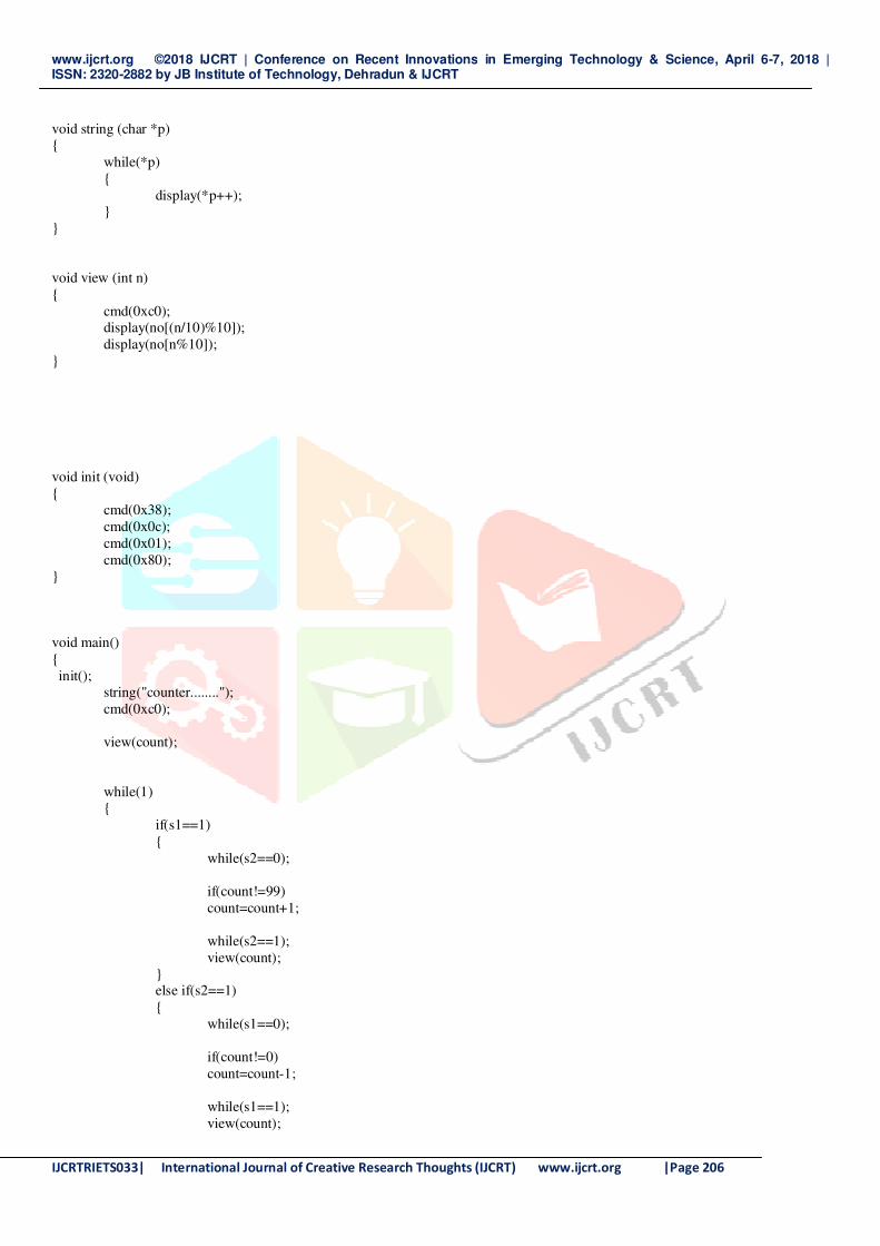
void string (char *p) {
while(*p)
{
display(*p++); }
}
void view (int n)
{
cmd(0xc0); display(no[(n/10)%10]);
display(no[n%10]);
}
void init (void)
{ cmd(0x38);
cmd(0x0c);
cmd(0x01);
cmd(0x80); }
void main()
{
init(); string("counter........");
cmd(0xc0);
view(count);
while(1) {
if(s1==1)
{
while(s2==0);
if(count!=99)
count=count+1;
while(s2==1);
view(count); } else if(s2==1)
{
while(s1==0);
if(count!=0)
count=count-1;
while(s1==1);
view(count);

www.ijcrt.org ©2018 IJCRT | Conference on Recent Innovations in Emerging Technology & Science, April 6-7, 2018 | ISSN: 2320-2882 by JB Institute of Technology, Dehradun & IJCRT
IJCRTRIETS033| International Journal of Creative Research Thoughts (IJCRT) www.ijcrt.org |Page 207
}
else if(count==1)
relay=0;
else if(count==0)
relay=1;
}
}
FUTURE EXPANSION:-
1. By using this circuit and proper power supply we can implement various applications Such as fans, tube lights, etc.
2. By modifying this circuit and using two relays we can achieve a task of opening and closing the door.
ADVANTAGES & DISADVANTAGES & APPLICATION,
• Advantages:-
1. Low cost
2. Easy to use 3. Implement in single door
• Disadvantages:-
4. It is used only when one single person cuts the rays of the sensor hence it cannot be used when two person cross
simultaneously.
www.ijcrt.org ©2018 IJCRT | Conference on Recent Innovations in Emerging Technology & Science, April 6-7, 2018 | ISSN: 2320-2882 by JB Institute of Technology, Dehradun & IJCRT
IJCRTRIETS033| International Journal of Creative Research Thoughts (IJCRT) www.ijcrt.org |Page 208
• Application:-
1. For counting purposes
2. For automatic room light control
• Reference Books
1. Programming in ANSI C: E BALAGURUSAMY
2. The 8051microcontroller and embedded systems: MUHAMMAD ALI MAZIDI
3. JANICE GILLISPIE MAZIDI 4. The 8051 microcontroller: KENNETH J. AYALA
• Website
1. www.datasheets4u.com
2. www.8051.com