AUTOMATIC PRODUCTS international, ltd. OPERATING SYSTEM … · 2018. 12. 4. · 75 west plato...
105
75 WEST PLATO BOULEVARD • ST. PAUL, MINNESOTA 55107-2095 AUTOMATIC PRODUCTS international, ltd. OPERATING SYSTEM PARTS MANUAL SERVICE MANUAL MODEL 123-123A-123B-123C GLASSFRONT MERCHANDISER PLEASE DO NOT REMOVE MANUAL FROM MACHINE APi 123 V4.0
Transcript of AUTOMATIC PRODUCTS international, ltd. OPERATING SYSTEM … · 2018. 12. 4. · 75 west plato...
75 WEST PLATO BOULEVARD • ST. PAUL, MINNESOTA 55107-2095
AUTOMATIC PRODUCTS international, ltd.
OPERATING SYSTEM
PARTS MANUAL
SERVICE MANUAL
MODEL 123-123A-123B-123C
GLASSFRONT MERCHANDISER
PLEASE DO NOT
REMOVE MANUAL
FROM MACHINE
APi 123 V4.0
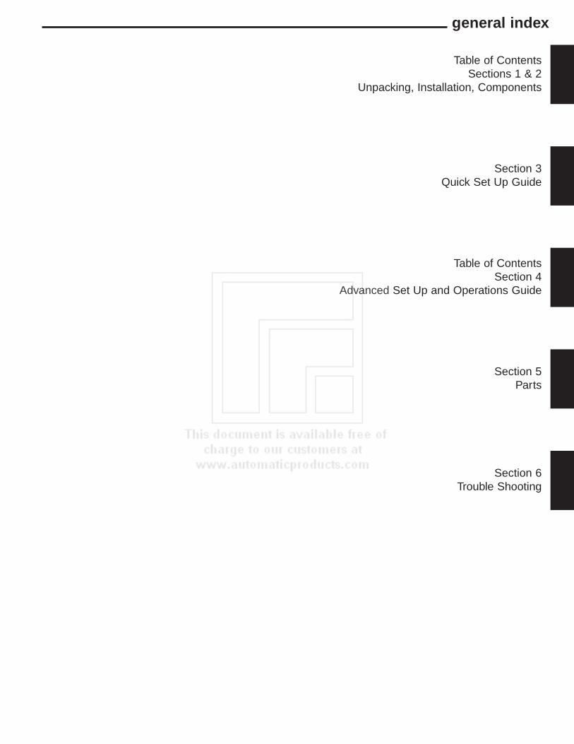
general index
Table of ContentsSections 1 & 2
Unpacking, Installation, Components
Section 3Quick Set Up Guide
Table of ContentsSection 4
Advanced Set Up and Operations Guide
Section 5Parts
Section 6Trouble Shooting

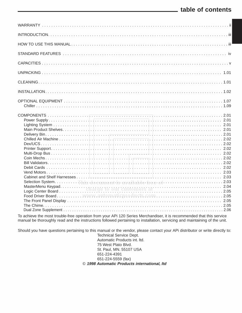
table of contents
WARRANTY . . . . . . . . . . . . . . . . . . . . . . . . . . . . . . . . . . . . . . . . . . . . . . . . . . . . . . . . . . . . . . . . . . . . . . . . . . . . . . . . . ii
INTRODUCTION. . . . . . . . . . . . . . . . . . . . . . . . . . . . . . . . . . . . . . . . . . . . . . . . . . . . . . . . . . . . . . . . . . . . . . . . . . . . . . iii
HOW TO USE THIS MANUAL . . . . . . . . . . . . . . . . . . . . . . . . . . . . . . . . . . . . . . . . . . . . . . . . . . . . . . . . . . . . . . . . . . . . iii
STANDARD FEATURES . . . . . . . . . . . . . . . . . . . . . . . . . . . . . . . . . . . . . . . . . . . . . . . . . . . . . . . . . . . . . . . . . . . . . . . iv
CAPACITIES . . . . . . . . . . . . . . . . . . . . . . . . . . . . . . . . . . . . . . . . . . . . . . . . . . . . . . . . . . . . . . . . . . . . . . . . . . . . . . . . . v
UNPACKING . . . . . . . . . . . . . . . . . . . . . . . . . . . . . . . . . . . . . . . . . . . . . . . . . . . . . . . . . . . . . . . . . . . . . . . . . . . . . . 1.01
CLEANING. . . . . . . . . . . . . . . . . . . . . . . . . . . . . . . . . . . . . . . . . . . . . . . . . . . . . . . . . . . . . . . . . . . . . . . . . . . . . . . . 1.01
INSTALLATION. . . . . . . . . . . . . . . . . . . . . . . . . . . . . . . . . . . . . . . . . . . . . . . . . . . . . . . . . . . . . . . . . . . . . . . . . . . . . 1.02
OPTIONAL EQUIPMENT . . . . . . . . . . . . . . . . . . . . . . . . . . . . . . . . . . . . . . . . . . . . . . . . . . . . . . . . . . . . . . . . . . . . . 1.07Chiller . . . . . . . . . . . . . . . . . . . . . . . . . . . . . . . . . . . . . . . . . . . . . . . . . . . . . . . . . . . . . . . . . . . . . . . . . . . . . . . . . 1.09
COMPONENTS . . . . . . . . . . . . . . . . . . . . . . . . . . . . . . . . . . . . . . . . . . . . . . . . . . . . . . . . . . . . . . . . . . . . . . . . . . . . 2.01Power Supply . . . . . . . . . . . . . . . . . . . . . . . . . . . . . . . . . . . . . . . . . . . . . . . . . . . . . . . . . . . . . . . . . . . . . . . . . . . 2.01Lighting System . . . . . . . . . . . . . . . . . . . . . . . . . . . . . . . . . . . . . . . . . . . . . . . . . . . . . . . . . . . . . . . . . . . . . . . . . 2.01Main Product Shelves. . . . . . . . . . . . . . . . . . . . . . . . . . . . . . . . . . . . . . . . . . . . . . . . . . . . . . . . . . . . . . . . . . . . . 2.01Delivery Bin. . . . . . . . . . . . . . . . . . . . . . . . . . . . . . . . . . . . . . . . . . . . . . . . . . . . . . . . . . . . . . . . . . . . . . . . . . . . . 2.01Chilled Air Machine . . . . . . . . . . . . . . . . . . . . . . . . . . . . . . . . . . . . . . . . . . . . . . . . . . . . . . . . . . . . . . . . . . . . . . . 2.02Dex/UCS . . . . . . . . . . . . . . . . . . . . . . . . . . . . . . . . . . . . . . . . . . . . . . . . . . . . . . . . . . . . . . . . . . . . . . . . . . . . . . . 2.02Printer Support . . . . . . . . . . . . . . . . . . . . . . . . . . . . . . . . . . . . . . . . . . . . . . . . . . . . . . . . . . . . . . . . . . . . . . . . . . 2.02Multi-Drop Bus . . . . . . . . . . . . . . . . . . . . . . . . . . . . . . . . . . . . . . . . . . . . . . . . . . . . . . . . . . . . . . . . . . . . . . . . . . 2.02Coin Mechs . . . . . . . . . . . . . . . . . . . . . . . . . . . . . . . . . . . . . . . . . . . . . . . . . . . . . . . . . . . . . . . . . . . . . . . . . . . . . 2.02Bill Validators. . . . . . . . . . . . . . . . . . . . . . . . . . . . . . . . . . . . . . . . . . . . . . . . . . . . . . . . . . . . . . . . . . . . . . . . . . . . 2.02Debit Cards . . . . . . . . . . . . . . . . . . . . . . . . . . . . . . . . . . . . . . . . . . . . . . . . . . . . . . . . . . . . . . . . . . . . . . . . . . . . 2.02Vend Motors . . . . . . . . . . . . . . . . . . . . . . . . . . . . . . . . . . . . . . . . . . . . . . . . . . . . . . . . . . . . . . . . . . . . . . . . . . . . 2.03Cabinet and Shelf Harnesses . . . . . . . . . . . . . . . . . . . . . . . . . . . . . . . . . . . . . . . . . . . . . . . . . . . . . . . . . . . . . . . 2.03Selection System. . . . . . . . . . . . . . . . . . . . . . . . . . . . . . . . . . . . . . . . . . . . . . . . . . . . . . . . . . . . . . . . . . . . . . . . . 2.03MasterMenu Keypad. . . . . . . . . . . . . . . . . . . . . . . . . . . . . . . . . . . . . . . . . . . . . . . . . . . . . . . . . . . . . . . . . . . . . . 2.04Logic Center Board . . . . . . . . . . . . . . . . . . . . . . . . . . . . . . . . . . . . . . . . . . . . . . . . . . . . . . . . . . . . . . . . . . . . . . . 2.05Food Driver Board . . . . . . . . . . . . . . . . . . . . . . . . . . . . . . . . . . . . . . . . . . . . . . . . . . . . . . . . . . . . . . . . . . . . . . . . 2.05The Front Panel Display . . . . . . . . . . . . . . . . . . . . . . . . . . . . . . . . . . . . . . . . . . . . . . . . . . . . . . . . . . . . . . . . . . . 2.05The Chime. . . . . . . . . . . . . . . . . . . . . . . . . . . . . . . . . . . . . . . . . . . . . . . . . . . . . . . . . . . . . . . . . . . . . . . . . . . . . . 2.05Dual Zone Supplement . . . . . . . . . . . . . . . . . . . . . . . . . . . . . . . . . . . . . . . . . . . . . . . . . . . . . . . . . . . . . . . . . . . . . . . . . 2.06
To achieve the most trouble-free operation from your APi 120 Series Merchandiser, it is recommended that this servicemanual be thoroughly read and the instructions followed pertaining to installation, servicing and maintaining of the unit.
Should you have questions pertaining to this manual or the vendor, please contact your APi distributor or write directly to:Technical Service Dept.Automatic Products int. ltd.75 West Plato Blvd.St. Paul, MN. 55107 USA651-224-4391651-224-5559 (fax)
© 1998 Automatic Products international, ltd

EXPRESS WARRANTY
ii
Automatic Products international ltd. (APi) expressly warrants these automatic merchandisers (the “Unit”),manufactured by it, to be free under normal use and service from defects in material or workmanship for aperiod of two (2) years from the date of delivery of this Unit to the original purchaser. This warranty extendsonly to the original purchaser of the Unit. The exclusive remedy for this warranty is limited to the repair orreplacement, at APi’s sole option, of any part or parts of the Unit that are returned to APi or to theauthorized dealer or distributor of APi from whom the unit was purchased with all transportation chargesprepaid, and which, on APi’s examination, shall, conclusively appear to have been defective.This warrantydoes not:
a. extend to any Unit, or part thereof, that was subjected to misuse, neglect, or accident by other than APiafter its delivery to the original purchaser;
b. extend to any Unit, or part thereof, that was modified, altered, incorrectly wired or improperly installedby anyone other than APi or used in violation of the instructions provided by APi;
c. extend to a Unit which has been repaired or altered by anyone other than APi or authorizeddealer/distributor;
d. extend to a Unit which has had the serial number removed, defaced or otherwise altered;
e. extend to plastic or glass windows, lamps, fluorescent tubes and water contact parts;
f. extend to any unit used outdoors;
g. extend to accessories used with the Unit that were manufactured by some person or entity other thanAPi.
APi DISCLAIMS ALL OTHER WARRANTIES OF ANY KIND AS TO THE UNIT AND ALL WARRANTIES OF ANYKIND AS TO ANY ACCESSORIES. THIS DISCLAIMER OF WARRANTIES INCLUDES ANY EXPRESSWARRANTIES OTHER THAN THE LIMITED WARRANTY PROVIDED ABOVE AS TO THE UNIT AND ALL IMPLIEDWARRANTIES OF MERCHANTABILITY AND FITNESS FOR A PARTICULAR PURPOSE AS TO THE UNIT ANDANY ACCESSORIES. UNDER NO CIRCUMSTANCES SHALL APi BE RESPONSIBLE FOR ANY INCIDENTAL,CONSEQUENTIAL OR SPECIAL DAMAGES, LOSSES OR EXPENSES ARISING FROM OR IN CONNECTION WITHTHE USE OF, OR THE INABILITY TO USE, THE GOODS FOR ANY PURPOSE WHATSOEVER. No representativeof APi or any other person is authorized to assume for APi, or agree to on behalf of APi, any other liabilityor warranty in connection with the sale of this unit.
APi reserves the right to make any changes or improvements in its products without notice and withoutobligation, and without being required to make corresponding changes or improvements in Unit theretoforemanufactured or sold.
75 West Plato BoulevardSt. Paul, MN 55107
iii
introduction
The APi 120 series features the MasterVend™ Control System and MasterMenu™ operating system which provide auser friendly menu to setup and configure the machine. The simple operation and built in flexibility of this system allowseach user to customize the menu system to their preference. The system can be configured to display service andoperational mode messages in any of six different languages and support up to 80 selections. Robust testing capabilityas well as extensive diagnostics and error reporting facilities are built in to provide ease of maintenance.
HOW TO USE THIS MANUALThis manual is divided into four basic parts:1. Unpacking and installation.2. Components.3. Quick Set up Guide.4. Advanced Set up and Operating System.5. Parts6. Troubleshooting.
CAUTION: Certain procedures in both the operating section and the servicesection require that voltage be on in the machine. Only trained personnel shouldperform this function. Exercise extreme caution while performing theseprocedures. These procedures will be marked with the lightening bolt symbol asit appears at left.
CAUTION: Certain procedures in both the operating section and the servicesection requires a qualified trained technician to perform the particular task athand. These procedures will be marked with the exclamation symbol as itappears at left.
◆◆◆◆◆◆◆◆
◆◆◆◆◆◆◆◆
◆◆◆◆◆◆◆◆◆◆◆◆◆◆◆◆◆◆◆◆◆◆◆◆◆◆◆◆◆◆◆◆◆
WATCH THROUGHOUT THE MANUAL FOR THIS SPECIAL ◆ DIAMOND MARK. THIS INDICATES A POINT OF SPECIAL INFORMATION OR A HINT THAT WILL ASSIST YOU IN SETTING UP, OPERATING OR TROUBLESHOOTING THE MACHINE.
◆◆◆◆◆◆◆◆◆◆◆◆◆◆◆◆◆◆◆◆◆◆◆◆◆◆◆◆◆◆◆◆◆
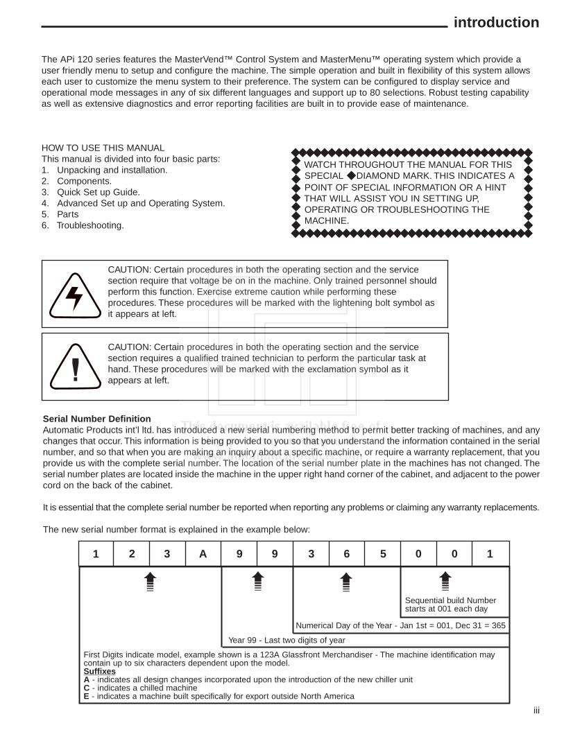
Serial Number DefinitionAutomatic Products int’l ltd. has introduced a new serial numbering method to permit better tracking of machines, and anychanges that occur. This information is being provided to you so that you understand the information contained in the serialnumber, and so that when you are making an inquiry about a specific machine, or require a warranty replacement, that youprovide us with the complete serial number. The location of the serial number plate in the machines has not changed. Theserial number plates are located inside the machine in the upper right hand corner of the cabinet, and adjacent to the powercord on the back of the cabinet.
It is essential that the complete serial number be reported when reporting any problems or claiming any warranty replacements.
The new serial number format is explained in the example below:
Sequential build Numberstarts at 001 each day
Numerical Day of the Year - Jan 1st = 001, Dec 31 = 365
Year 99 - Last two digits of year
First Digits indicate model, example shown is a 123A Glassfront Merchandiser - The machine identification maycontain up to six characters dependent upon the model.SuffixesA - indicates all design changes incorporated upon the introduction of the new chiller unitC - indicates a chilled machineE - indicates a machine built specifically for export outside North America
1 2 3 A 9 9 3 6 5 0 0 1
➠➠➠➠
iv
STANDARD FEATURES
■ Up to 80 selections.■ Multi drop buss capabilities.■ Extensive diagnostics capabilities.■ Friendly text based interface.■ Configuration upload and download capabilities.■ User programmable function keys.■ Flexible spiral spacing for large products.■ Eight point star drive motor.■ Four security levels.■ Six languages.■ Machine reset capability.■ Real time clock.■ Personal computer interface.■ Printer interface.■ Chime.
PRICING
■ Global pricing by machine or by shelf.■ Extensive discounting capabilities.■ Shutdown capabilities.■ Combo vends.■ Product codes.■ Programmable spiral count.■ Upload and download capabilities for pricing
and set up.■ Programmable maximum payout.■ Extensive accountability, including all
discounts and free vends.
SCROLLING DISPLAY
■ User friendly scrolling display to help with theselection process and provide customerfeedback.
■ User programmable point of sale and■ operational messages.■ 20 character display.
OPTIONS
■ Point of sale window.■ Delivery bin cushion.■ Base kit.■ Lexan window.■ MasterMenu™ online software.■ Transportable memory unit.
NOISE LEVEL
Operates at less than 70 db (A).
ACCEPTABLE AMBIENT OPERATING TEMPERATURE RANGE
All equipment manufactured by Automatic Products intl.Ltd. is designed to work properly in a temperature rangeof 10˚C to 38˚C (50˚F to 100˚F) in still air (75% R.H. non-condensing). The machine is capable of being stored in atemperature range of -18˚C to 68˚C (0˚F to 155˚F).
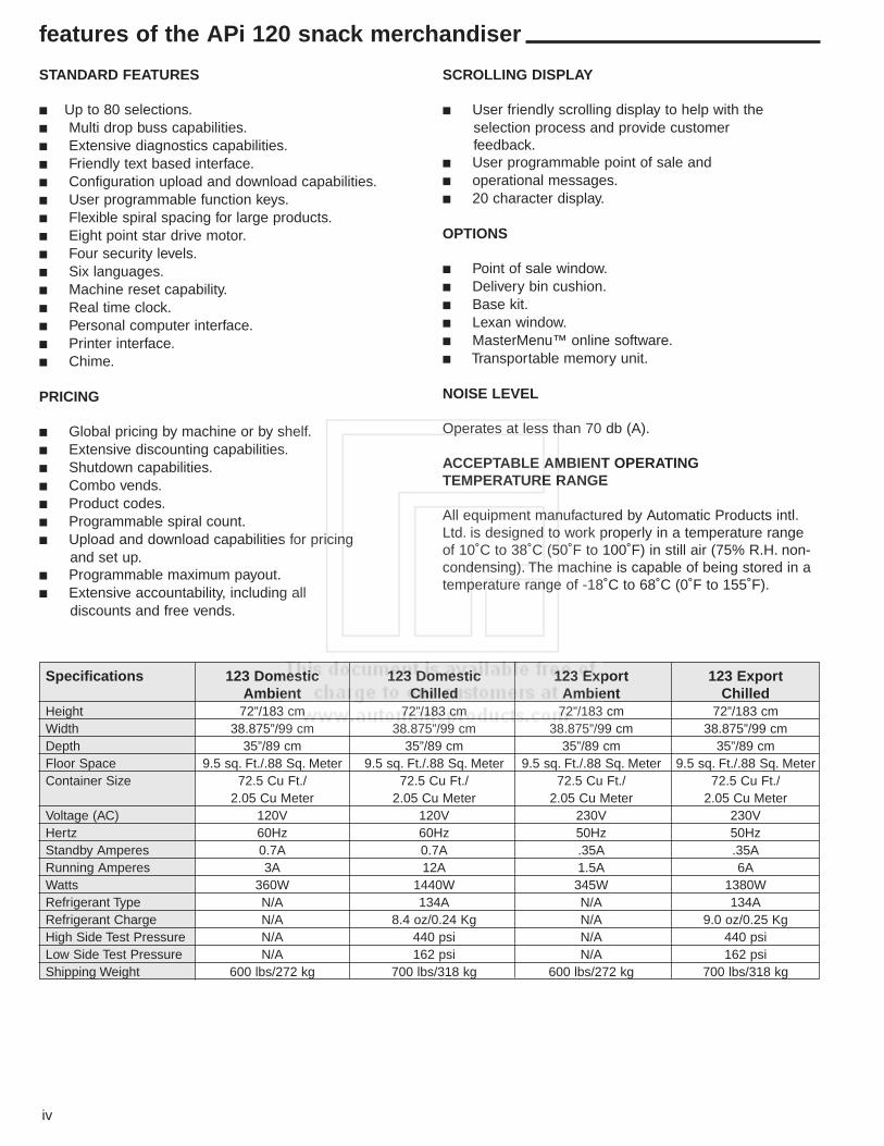
features of the APi 120 snack merchandiser
Specifications 123 Domestic 123 Domestic 123 Export 123 ExportAmbient Chilled Ambient Chilled
Height 72”/183 cm 72”/183 cm 72”/183 cm 72”/183 cmWidth 38.875”/99 cm 38.875”/99 cm 38.875”/99 cm 38.875”/99 cmDepth 35”/89 cm 35”/89 cm 35”/89 cm 35”/89 cmFloor Space 9.5 sq. Ft./.88 Sq. Meter 9.5 sq. Ft./.88 Sq. Meter 9.5 sq. Ft./.88 Sq. Meter 9.5 sq. Ft./.88 Sq. MeterContainer Size 72.5 Cu Ft./ 72.5 Cu Ft./ 72.5 Cu Ft./ 72.5 Cu Ft./
2.05 Cu Meter 2.05 Cu Meter 2.05 Cu Meter 2.05 Cu MeterVoltage (AC) 120V 120V 230V 230VHertz 60Hz 60Hz 50Hz 50HzStandby Amperes 0.7A 0.7A .35A .35ARunning Amperes 3A 12A 1.5A 6AWatts 360W 1440W 345W 1380WRefrigerant Type N/A 134A N/A 134ARefrigerant Charge N/A 8.4 oz/0.24 Kg N/A 9.0 oz/0.25 KgHigh Side Test Pressure N/A 440 psi N/A 440 psiLow Side Test Pressure N/A 162 psi N/A 162 psiShipping Weight 600 lbs/272 kg 700 lbs/318 kg 600 lbs/272 kg 700 lbs/318 kg
capacities
v
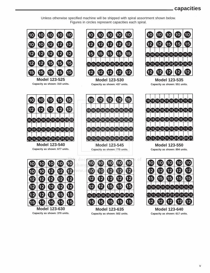
Model 123-525Capacity as shown: 310 units.
Model 123-530Capacity as shown: 437 units.
Model 123-535Capacity as shown: 551 units.
Model 123-540Capacity as shown: 677 units.
Model 123-545Capacity as shown: 775 units.
Model 123-550Capacity as shown: 894 units.
Model 123-630Capacity as shown: 370 units.
Model 123-635Capacity as shown: 502 units.
Model 123-640Capacity as shown: 617 units.
Unless otherwise specified machine will be shipped with spiral assortment shown below.Figures in circles represent capacities each spiral.
vi
capacities
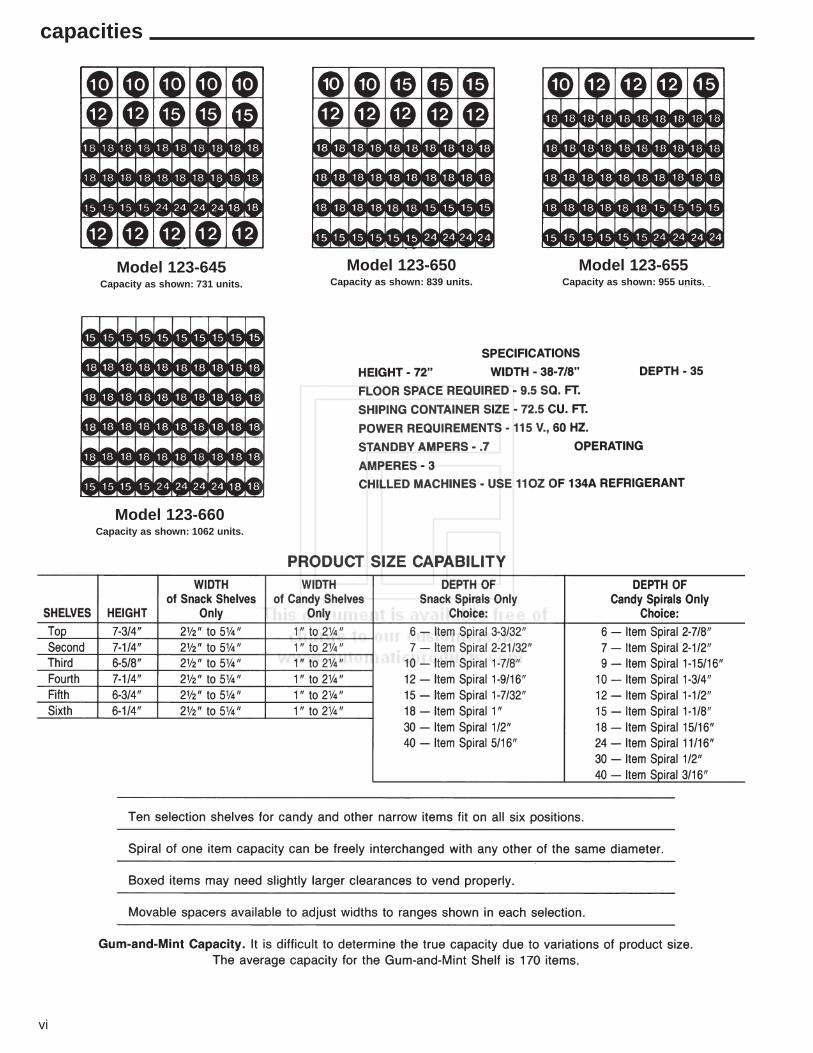
Model 123-645Capacity as shown: 731 units.
Model 123-650Capacity as shown: 839 units.
Model 123-655Capacity as shown: 955 units.
Model 123-660Capacity as shown: 1062 units.

1.01
unpacking
The Snackshop 123 is assembled and packed so that aminimum amount of time is necessary for preparation toinstall it on location. The following steps arerecommended to insure correct unpacking.
1. Shipping Damage: Thoroughly inspect the exterior ofthe carton for damage which may have occurred during shipment. Report any damage to delivering carrier and follow their instructions.
2. Remove staples from lower edge and those at top of carton, and slit carton vertically at the taped corner.Open and remove carton. Remove the remainder of the packing material. On machines shipped with lock in place, the keys are taped inside the coin return.
3. Remove Vendor with a Forklift Truck: Remove the carton from the vendor. From the front of the vendor tip the vendor backward and run forks under the cabinet.
4. Removing Vendor Without a Forklift Truck: Remove the carton from the vendor. Break off the thin piece of board behind the rear legs. From the front of the machine tip the vendor back enough to clear the lowerlegs from the holes in the front board. Push the machine back off the base. Remove the pallet.
NOTE: Because the weight concentration is toward the back of the cabinet, trucking and lifting should be done from the back. CAUTION should be taken when trucking from side.
5. On machines with lock in place, unlock, and turn handle to open door. When no lock is furnished, remove clip and turn handle. Swing door to its full open position.
6. Remove all packing tape and paper from various areas of machine and the shipping strap.
7. Warranty: The warranty card is attached to the cover of this manual. It must be filled out in full and mailed at once to insure coverage.
◆ IMPORTANT: A set of anchoring brackets are sent
with each machine. The kit is located in the bottom of the machine complete with instructions. It isrecommended that this kit be installed to prevent shifting of the machine.
CLEANING
The Snackshop 120 series will do the best merchandisingjob for you if it is kept clean. The display window can becleaned with any good glass cleaner. The exterior andinterior surfaces should be cleaned with warm water andmild detergent. Rinse thoroughly and dry all surfaces.
CAUTION: Do not use any cleaners containing silicon asthis could cause electrical failures.
The main product shelves can be best cleaned with thespirals and product spacers removed. Refer to page 1.03for removal of spirals and removal of the product spacers.
Clean the acceptor on the coin mechanism frequently asaccumulated dirt in this area can cause coins to hang ornot be accepted. Follow recommended cleaningprocedures as described by the manufacturer.
Leveling the Machine: on location is important for theproper function of the machine. The four leveling screwsin the legs are the means of leveling the machine. Afterpositioning the machine, level machine in front to rear andright to left directions. After leveling, turn front right(lock side) leveling screw in about one-half turn to dropthis corner slightly to make the door easier to close andlock.
Voltage and Polarity CheckIt is important that this machine is hookedup to the proper voltage and polarity.Using a voltmeter, perform the followingchecks from the illustration below.
NOTE: Should the readings be different fromabove, have a certified electrician correct theproblem.
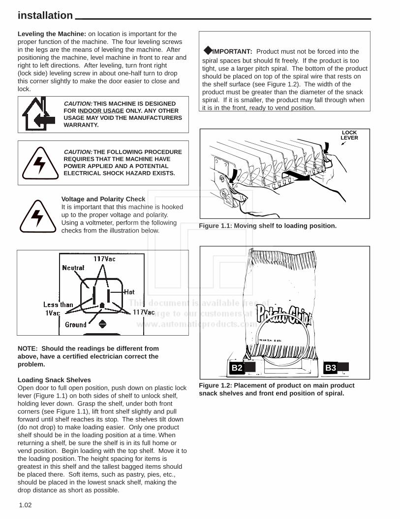
Loading Snack ShelvesOpen door to full open position, push down on plastic locklever (Figure 1.1) on both sides of shelf to unlock shelf,holding lever down. Grasp the shelf, under both frontcorners (see Figure 1.1), lift front shelf slightly and pullforward until shelf reaches its stop. The shelves tilt down(do not drop) to make loading easier. Only one productshelf should be in the loading position at a time. Whenreturning a shelf, be sure the shelf is in its full home orvend position. Begin loading with the top shelf. Move it tothe loading position. The height spacing for items isgreatest in this shelf and the tallest bagged items shouldbe placed there. Soft items, such as pastry, pies, etc.,should be placed in the lowest snack shelf, making thedrop distance as short as possible.
◆ IMPORTANT: Product must not be forced into thespiral spaces but should fit freely. If the product is too tight, use a larger pitch spiral. The bottom of the product should be placed on top of the spiral wire that rests onthe shelf surface (see Figure 1.2). The width of the product must be greater than the diameter of the snack spiral. If it is smaller, the product may fall through when it is in the front, ready to vend position.
1.02
installation
LOCKLEVER
B2 B3
CAUTION: THIS MACHINE IS DESIGNEDFOR INDOOR USAGE ONLY. ANY OTHERUSAGE MAY VOID THE MANUFACTURERSWARRANTY.
CAUTION: THE FOLLOWING PROCEDUREREQUIRES THAT THE MACHINE HAVEPOWER APPLIED AND A POTENTIALELECTRICAL SHOCK HAZARD EXISTS.
Figure 1.1: Moving shelf to loading position.
Figure 1.2: Placement of product on main productsnack shelves and front end position of spiral.
Adjusting the Stopping Position of the Spiral.One primary difference that distinguishes the new motorsfrom previous motors is the presence of an eight sidedstar at the drive hub of the motor. This permits thestopping position of the spiral to be customized by theoperator to ensure the best possible delivery of product.To change the stopping position of the spiral, remove thespiral lock from the motor by pinching the shaft of thespiral lock from the back side of the motor and pullingforward on the front side of the spiral lock. The spiral lockcan be reinstalled in any of eight different positions byturning the spiral lock to the position desired and pushingthe shaft of the spiral lock through the eight sided star atthe drive hub of the motor.
Removal of SpiralGrasp the front of the spiral and turn it clockwise. Lift thespiral up and off of the spiral lock. When replacing a spiralattach it around the tab on the spiral lock and turn thespiral counterclockwise to lock it in place. Be sure thefront end of the spiral is positioned properly (with the frontend if the spiral pointing downward on the left side) (seeFigure 1.3). Give a light forward pull on front of the spiralto check it is locked in place.
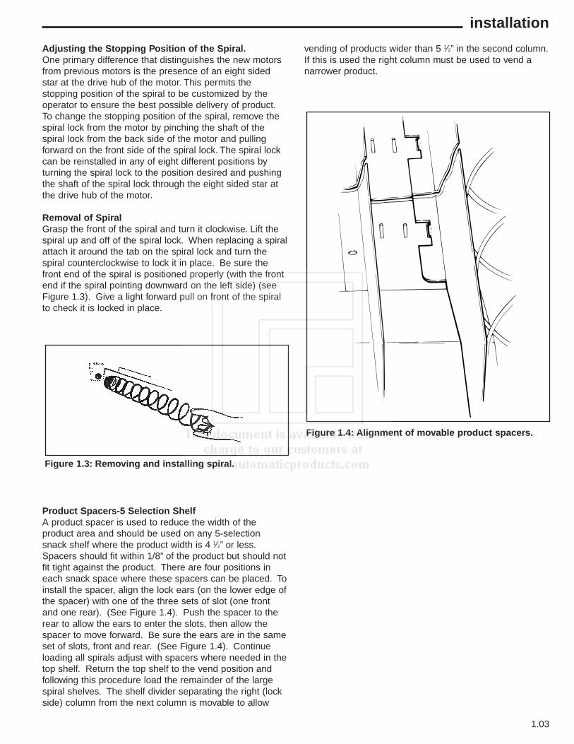
Product Spacers-5 Selection ShelfA product spacer is used to reduce the width of theproduct area and should be used on any 5-selectionsnack shelf where the product width is 4 1⁄2” or less.Spacers should fit within 1/8” of the product but should notfit tight against the product. There are four positions ineach snack space where these spacers can be placed. Toinstall the spacer, align the lock ears (on the lower edge ofthe spacer) with one of the three sets of slot (one frontand one rear). (See Figure 1.4). Push the spacer to therear to allow the ears to enter the slots, then allow thespacer to move forward. Be sure the ears are in the sameset of slots, front and rear. (See Figure 1.4). Continueloading all spirals adjust with spacers where needed in thetop shelf. Return the top shelf to the vend position andfollowing this procedure load the remainder of the largespiral shelves. The shelf divider separating the right (lockside) column from the next column is movable to allow
vending of products wider than 5 1⁄2” in the second column.If this is used the right column must be used to vend anarrower product.
1.03
installation
Figure 1.3: Removing and installing spiral.
Figure 1.4: Alignment of movable product spacers.

Loading Main Product Candy ShelvesThe 10-selection (candy type) shelves are loaded similarto the 5-selection shelves except that the bottom of theproduct sits on the shelf in front of the spiral wire (seeFigure 1.5) that rests on the shelf. These products mustalso fit properly product in the spiral space; do not forceproduct into spiral.
These spirals are removed and installed the same as thelarge spiral (see Figure 3), except that the front endposition is different (approximately 5 o’clock)(see Figure1.5) and the front left side of the spiral must be behind thesmall tab located on the left side of the product space sidewall (see Figure 1.5, Detail A).
Product Spacers-10 Selection ShelfThe 10-selection shelves are equipped with a productspacer (see Figure 1.6) that can be pivoted from the rightside of every other product space. These spacers shouldbe pivoted out to hold the product upright, but not tightagainst the product. Leave about 1/8” clearance betweenthe spacer and the product.
1.04
installation
DETAILA
E3
Figure 1.5: Placement of product on main productcandy shelves and front end position of spiral.
Figure 1.6: 10 selection shelf product spacerpositioned to hold candy upright.
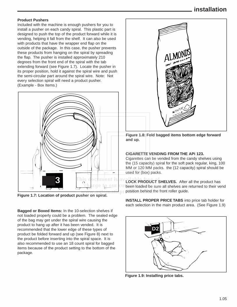
Product PushersIncluded with the machine is enough pushers for you toinstall a pusher on each candy spiral. This plastic part isdesigned to push the top of the product forward while it isvending, helping it fall from the shelf. It can also be usedwith products that have the wrapper end flap on theoutside of the package. In this case, the pusher preventsthese products from hanging on the spiral by spreadingthe flap. The pusher is installed approximately 210degrees from the front end of the spiral with the tabextending forward (see Figure 1.7). Locate the pusher inits proper position, hold it against the spiral wire and pushthe semi-circular part around the spiral wire. Note: Notevery selection spiral will need a product pusher.(Example - Box Items.)
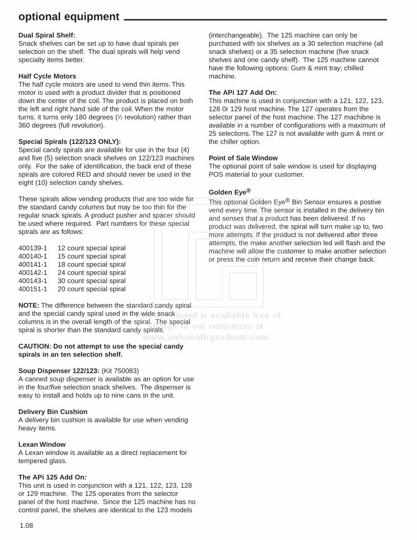
Bagged or Boxed Items: In the 10-selection shelves ifnot loaded properly could be a problem. The sealed edgeof the bag may get under the spiral wire causing theproduct to hang up after it has been vended. It isrecommended that the lower edge of these types ofproduct be folded forward and up (see Figure 8) next tothe product before inserting into the spiral space. It isalso recommended to use an 18 count spiral for baggeditems because of the product setting to the bottom of thepackage.
CIGARETTE VENDING FROM THE APi 123.Cigarettes can be vended from the candy shelves usingthe (15 capacity) spiral for the soft pack regular, king, 100MM or 120 MM packs. the (12 capacity) spiral should beused for (box) packs.
LOCK PRODUCT SHELVES. After all the product hasbeen loaded be sure all shelves are returned to their vendposition behind the front roller guide.
INSTALL PROPER PRICE TABS into price tab holder foreach selection in the main product area. (See Figure 1.9)
1.05
installation
Figure 1.7: Location of product pusher on spiral.
Figure 1.8: Fold bagged items bottom edge forwardand up.
Figure 1.9: Installing price tabs.

Loading Gum and Mints:The Gum and Mint shelf is located below the lowestSnack Shelf (optional). Unlatch the shelf by pulling forwardthe two metal latches located to the right and left of theshelf and pull forward. The cover can be pushed back tothe rear for easy loading. The shelf contains fourindividual selections.
The first selection on the left contains two fillers for usewith thin mints. (Rolaids - Certs, etc.). These fillers canbe removed for standard gum or mints.
The two selections on the right of the Gum and Mint shelfalso have fillers. These selections can be used forstandard size gum and mints or the fillers may beremoved for larger gum and mint products.
Each selection has a display hinge assembly which shouldbe adjusted after the shelf is loaded. To adjust the displayhinge, loosen the wing nut and slide the spring hinge ofthe flipper over the second product and fasten tightly.
◆ Be sure to close the cover on the gum and mint shelf
before pushing the shelf back to its home position.
◆ The gum and mint shelf can be used as a loading
platform while filling the machine. The maxium load of the gum and mint shelf is 35 pounds.
Connecting a 320 to a 120 Series Snack.A 320 machine can also be controlled by a120 Series snack merchandiser in lieu of aControl module. The following is a list ofsteps required to connect a 320 (AL A
CARTE) machine to a 120 series snack machine.
1. Locate the interconnect harness coming out of the back side of the food cabinet and route it into the back side of the snack (remove the triangular plate just above the line cord) to the LogiCenter board and plug into the P8 connector. (Bottom Right)
2. The 320 machine is considered Cabinet 2 when connected to a 120. Make sure the Jumper on the Food Driver Board (FDB) is set to cabinet 2.
3. Set the Temperature Control jumper on the FDB to the appropriate temperature setting. R for a refrigerated machine, F for a frozen machine. NOTE: This jumper is only a default setting, if for any reason the snackmachine looses communications with the food/frozen machine this setting takes over.
4. All programming for the 320 (cabinet 2) is done in the snack machine. The following items must be programmed for the 320 machine to operate correctly,:
A. Set Motor Pairs by pressing and holding down the * key while pressing F1 on the MasterMenu keypad.
B. Set Temperature for Cabinet 2 by pressing and holding down the * key while pressing F2 on the MasterMenu keypad.
C. Set Prices by pressing F4 on the MasterMenu keypad.
NOTE: All selections in the 320 will start with thenumber 2 and all selections in the snack will start withthe number 1. The item tabs on the 320 are reversible.
For Detailed information on setting up a 320 (A LA Carte)merchandiser, please refer to the 320 Service Manualpaying special attention to the two blue pages in themiddle of the book with the heading “Quick Set upReference”.
1.06
components

MasterMenu Online Software
MasterMenu Online software gives you the capability ofcompletely setting up any 120 Series Snack merchandiser,310 Control Module, 320 food merchandiser, or 223 Hotbeverage merchandiser machine on your personalcomputer (PC).MasterMenu Online also has the ability toload complete new logic board software revisions to amachine. To load complete new software into a machinethe PC must be connected directly to the machine logicboard via a cable P/N 56800022 and the DEX/UCSharness P/N 680509 . These updates can be sent to youvia e-mail or as a file on a floppy disk.
MasterMenu Online Installation
Personal Computer Requirements
To install MasterMenu Online, you need:
• Personal or Multimedia computer with a 486 orhigher processor.
• Microsoft Windows 95 operating system or later.• 16 MB of Ram.• 5 MB of hard disk required.• VGA or higher resolution video adapter.• Microsoft Mouse or Compatible pointing device.• 3.5 inch floppy drive
CHIPTwo pieces are required to use CHIP, the touch memorybutton (CHIP) and an Upload/download Harness thatallows Chip to communicate with the machine.
Touch Memory Button (Pn 17500003)The Touch Memory Button (CHIP) can be used todownload to or upload from any 310 Control Module orAPi 20 Series machine. CHIP is capable of storing allsettable data from a machine, with the exception of thetime and date. Once CHIP is programed you can take it toas many machines as you wish to upload the informationstored in CHIP. CHIP can be overwritten and reused asmany times as desired. CHIP is mounted on a key chainholder. CHIP can be programed from a machine that isalready set up and then used to set up other machinesthat are to be programed identically.
CHIP can also be programed from MasterMenu Online,MasterMenu Online is a software program that allows youto set up any 310 Control Module or 20 Series machineon your personal computer (PC). This information can thenbe stored by filename in you PC and is always accessiblefor any changes you may want to make the machine in thefuture, including pricing. To load CHIP from your PCrequires harness (Pn 17500004), included in this package.
Touch Memory Button (CHIP) and Upload/downloadHarness (Pn 16800013)
The CHIP upload/download harness is attached to theLogic Board (LCB) on J1 (upper right hand corner) andthe other end is mounted on the swing panel in adepression just above the display, six of these harnessesincluded in this package.
Chip Upload and Download Instructions.
1. Open Machine/Tower door, the display shouldindicate “Enter for MasterMenu”.
2. Press Enter3. Press the > until the display indicates
“Configuration”.4. Press Enter5. Press the > until the display indicates
“Configuration Load”.6. Press Enter, the display should read
“MasterMenu Online”.7. Press the + until the display indicates “Tmu
Upload” ( from Tmu to Lcb) or “Tmu Download”(From board to Tmu).
8. Press Enter9. The display will indicate “Awaiting Download” or
“Awaiting Upload”.10. Press the memory button CHIP against the socket
and the display will indicate “Transfer in Progress”.When the transfer is complete the display willprompt “Transfer Complete”. If for any reason thetransfer was unsuccessful the display will prompt“Transfer Error”.
Note: To Use MasterMenu Online or Chip the Softwareon the Logic Board must Be at the Following Revisionor Higher:3.5 Flash Memory and 3.0 Microprocessor
Ventilating Fan:(Part #660441 - 120 Volts)(Part #660441-1 - 240 Volts) ExportThe ventilating fan keeps a steady flow of air movingthrough the vendor cabinet. Installation of the fan takesonly a few minutes. All vendors are wired with a fan plugon the junction box for easy installation.
Base Kits:Base kits are available to make the vendor compatiblewith other manufacturers.
Gum and Mint:Gum and Mint units are available as an option with APi120 series vendors. For information pertaining to loadingor servicing gum and mint unit, refer to this servicemanual for loading instructions and service instructions.
1.07
optional equipment
Dual Spiral Shelf:Snack shelves can be set up to have dual spirals perselection on the shelf. The dual spirals will help vendspecialty items better.
Half Cycle MotorsThe half cycle motors are used to vend thin items. Thismotor is used with a product divider that is positioneddown the center of the coil. The product is placed on boththe left and right hand side of the coil. When the motorturns, it turns only 180 degrees (1⁄2 revolution) rather than360 degrees (full revolution).
Special Spirals (122/123 ONLY):Special candy spirals are available for use in the four (4)and five (5) selection snack shelves on 122/123 machinesonly. For the sake of identification, the back end of thesespirals are colored RED and should never be used in theeight (10) selection candy shelves.
These spirals allow vending products that are too wide forthe standard candy columns but may be too thin for theregular snack spirals. A product pusher and spacer shouldbe used where required. Part numbers for these specialspirals are as follows:
400139-1 12 count special spiral400140-1 15 count special spiral400141-1 18 count special spiral400142-1 24 count special spiral400143-1 30 count special spiral400151-1 20 count special spiral
NOTE: The difference between the standard candy spiraland the special candy spiral used in the wide snackcolumns is in the overall length of the spiral. The specialspiral is shorter than the standard candy spirals.
CAUTION: Do not attempt to use the special candyspirals in an ten selection shelf.
Soup Dispenser 122/123: (Kit 750083)A canned soup dispenser is available as an option for usein the four/five selection snack shelves. The dispenser iseasy to install and holds up to nine cans in the unit.
Delivery Bin CushionA delivery bin cushion is available for use when vendingheavy items.
Lexan WindowA Lexan window is available as a direct replacement fortempered glass.
The APi 125 Add On:This unit is used in conjunction with a 121, 122, 123, 128or 129 machine. The 125 operates from the selectorpanel of the host machine. Since the 125 machine has nocontrol panel, the shelves are identical to the 123 models
(interchangeable). The 125 machine can only bepurchased with six shelves as a 30 selection machine (allsnack shelves) or a 35 selection machine (five snackshelves and one candy shelf). The 125 machine cannothave the following options: Gum & mint tray; chilledmachine.
The APi 127 Add On:This machine is used in conjunction with a 121, 122, 123,128 0r 129 host machine. The 127 operates from theselector panel of the host machine. The 127 machibne isavailable in a number of configurations with a maximum of25 selections. The 127 is not available with gum & mint orthe chiller option.
Point of Sale WindowThe optional point of sale window is used for displayingPOS material to your customer.
Golden Eye®
This optional Golden Eye® Bin Sensor ensures a postivevend every time. The sensor is installed in the delivery binand senses that a product has been delivered. If noproduct was delivered, the spiral will turn make up to, twomore attempts. If the product is not delivered after threeattempts, the make another selection led will flash and themachine will allow the customer to make another selectionor press the coin return and receive their change back.
1.08
optional equipment
The Refrigeration Unit The Chiller unit is comprised of a 1/3 horsepowercompressor and is a hermetically sealed system (noservice ports). The compressor assembly is easilyremoved by taking out two screws and pulling the unitforward out the front of the cabinet. There is a wedgeshaped insulator above the evaporator that mates with amatching wedge in the cabinet to ensure a tight seal. Therefrigerant used in the refrigeration system is 134a andthe charge is 11 ounces. The refrigeration system iscontrolled by the Digital Temperature Control. Note: TheChiller can NOT be added at a later date. The 120series glass front merchandisers are designed to operateat ambient temperature of 55˚F to 100˚F (13˚C to 38˚C).
Digital Temperature ControlThe Digital Temperature Control is located in the powersupply box that is located behind the swing panel. TheDigital Temperature Control Board contains a digitaldisplay and two programming buttons. There is a windowtoward the bottom of the power supply box that allows youto view the current temperature in the can compartment inCelcius only. To view the temperature in Farhrenheit, pressand hold the 0 button for 3 seconds, and the currenttemperature will be shown on the main digital display.Located below the display window are the twoprogramming buttons. Power to operate the DigitalTemperature Control is supplied via the MDB connector onthe logic board using communications cable P/N 660659.Power to operate refrigeration unit is supplied to theDigital Temperature Control Board immediately after theEMI filter and is switched on and off by a relay on theDigital Temperature Control Board. Note: The only settingthat is programmed on the digital temperature controlis the Fan Speed when you have a chilled Snack area..
Settable Temperature Range:The settable temperature range is from 32˚F to 70˚F (0˚C to20˚C). The recommenced temperature for this machine is42˚F (6˚C). The Digital Temperature Control will maintain thetemperature as measured by the temperature probe (P/N13600001-01). The harness for the probe is plugged onto theDigital Temperature Control Board at the connector markedJP3. The probe is mounted in cabinet below the bottom shelfon the right hand side, just above the intake air of the evapo-rator. An unplugged or open temperature sensor prone will dis-play as -9˚F (-9˚C). A shorted or closed probe will display as99˚F (37˚C).
Setting the Target Temperature:The temperature setting is programmed in the logic Board.The Digital Temperature Control will allow you to set thetemperature but it will change back to what is programmedin the logic board. To set the temperature:1. Press and hold the * key while pressing the F1 button,
the display will prompt “Set temperatures”.2. Press Enter, the display will prompt “CAB 1 AMBIENT --- F”.3. Press the > and the t in ambient will start flashing.4. Press the + key until the display says
“CAB 1 CHILLED +10 F”.5. Press the > and the “+10” will start flashing.6. Press the + or - key to change the display to the desired
temperature and press enter to set the temperatureshown.
NOTE: To set temperatures in Celcius, Press the > to“F” and use the + key to change it to “C”.
Refrigeration Processing:The Digital Temperature Control maintains thetemperature as measured by the temperature sensor. Thechiller unit will be turned on at the set temperature plus2˚F and will be turned off at the target temperature minus2˚F. A minimum of 1 minute is required for both the cycleon and cycle off time of the relay. This insures thecompressor is not cycled on and/or off to rapidly.Independent of the temperature, the relay, therefore thecompressor, will be off 7 minutes every hour for a defrostcycle. The power for the Evaporator fan motor is constantand is not switched by the relay.
1.09
optional equipment
2.01
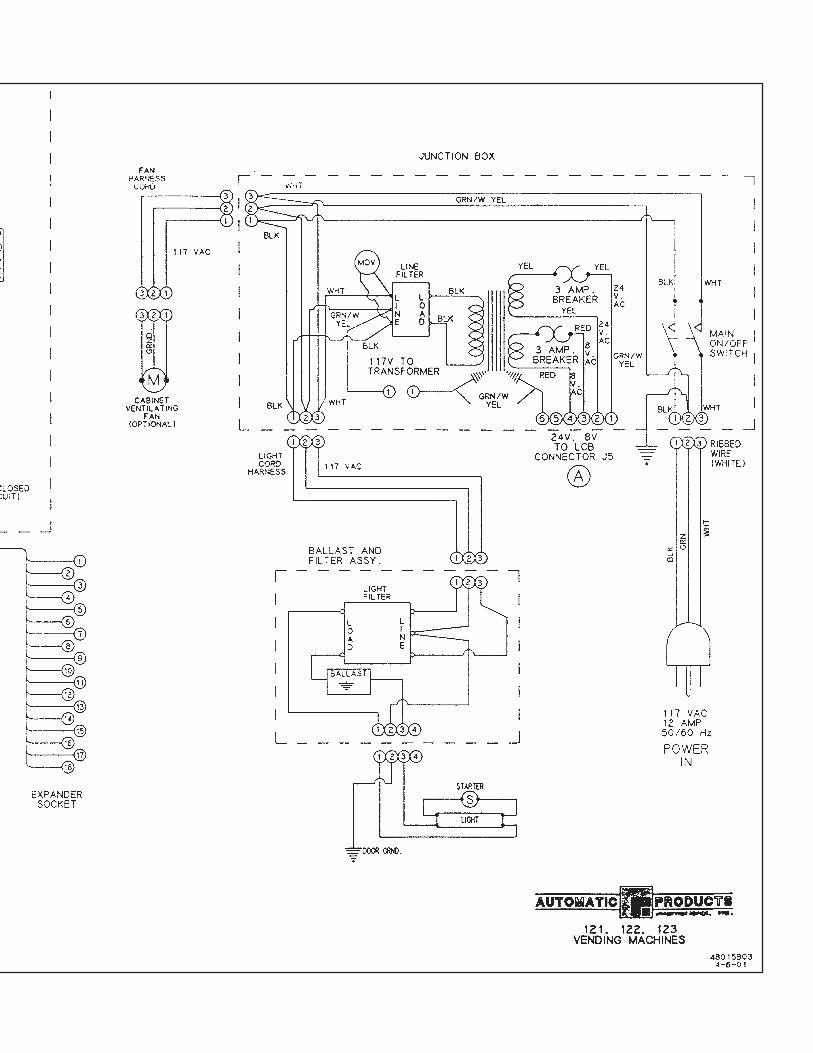
Power SupplyThe 115 VAC power cord from the wall outlet comes intothe machine and plugs into the back of the main junctionbox located on the bottom right side of the cabinet. Thevoltage output to the board is 24 volts and 8 volts and isplugged into the (L5 position) of the Logic Center Board.
Lighting SystemThere is only one fluorescent lamp in the Snackshop 120series. The lamp is located on the top of the door andlights up the main product area. The starter is located onthe hinge side of the lamp. The ballast and line filter islocated on the top front left shelf support. Bulb part#380022-5 (F18T8/CW-24).
Main Product Shelves:There are five or six main product shelves per machine.Each selection has its own motor mounted to the back ofthe shelf. Every shelf has its own harness and plug forconnecting to the remainder of the circuit through thecabinet receptacle, located in the rear right of the cabinet.The motors are the same on either shelf. It is possible inthe Snackshop 120 series to exchange a five selectionshelf with a ten selection shelf or visa versa. You alsohave the capability to gain 1⁄2 inch either up or down onany shelf. To do this the shelf should be removed and thecabinet back harness receptacle lowered or raised withthe right & left shelf tracks.
Note: When exchanging the shelves, you will not needany parts but you will have to reprogram the machines forprices and selections.
Removal of Product Shelf:A. Lift up and push the lock levers toward the back of
cabinet.B. Pull the shelf to its loading position.C. Grasp shelf in front and rear center. Lift front of shelf
up above horizontal and pull shelf forward while lifting.D. To install shelf, reverse above procedure.
Delivery Bin:This is located below the display window on the door andis mechanically operated. The linkage on the hinge sideof the delivery bin may require occasional lubrication.Should the door become difficult to operate, place a smallamount of grease on the arm tracks.
Removal of Delivery Bin:A. Remove the screws from the left and right side of the
delivery bin. These screws fasten into the lower door brace. Remove the two screws and brackets at the top of the delivery bin.
B. Grasp delivery bin on both sides and lift up and pull back. Should the bin be tight, rock it by lifting on one end, then the other.
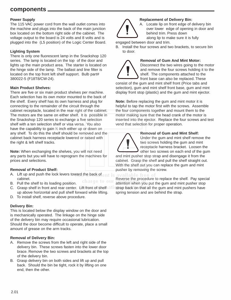
Replacement of Delivery Bin:A. Locate lip on front edge of delivery bin
over lower edge of opening in door andbehind trim. Press down along lip to make sure it is fully
engaged between door and trim.B. Install the four screws and two brackets, to secure bin
to door.
Removal of Gum And Mint Motor:Disconnect the two wires going to the motorand remove the four screws holding it to theshelf. The components attached to thefront base can also be replaced. These
consist of the gum and mint shelf front (Price tabs andselection), gum and mint shelf front base, gum and mintdisplay front stop (plastic) and the gum and mint ejector.
Note: Before replacing the gum and mint motor it ishelpful to tap the motor first with the screws. Assemblethe four components together and mount them to themotor making sure that the head crank of the motor isinserted into the ejector. Replace the four screws and testvend that selection for proper operation.
Removal of Gum and Mint Shelf:Under the gum and mint shelf remove thetwo screws holding the gum and mintreceptacle harness bracket. Loosen theother two screws on each end of the gum
and mint pusher stop strap and disengage it from thecabinet. Grasp the shelf and pull the shelf straight out.With the shelf out you can replace the gum and mintpusher by removing the screw.
Reverse the procedure to replace the shelf. Pay specialattention when you put the gum and mint pusher stopstrap back on that all the gum and mint pushers havespring tension and are behind the strap.
components
2.02
DEX/UCSThe APi 120 supports DEX/UCS CommunicationsProtocol - NAMA Vending Industry Data RetrievalStandard. The machine will automatically recognize theDEX/UCS device when it is plugged into the control boardand will recognize when the device initiates thecommunication protocol. The transmission/reception ofdata to the device will then take place automatically.
Printer SupportThe machine is able to print to a 40 character wide printerconnected to the serial port. The communication is asspecified by the user in the Printer Setup Menu . Themachine uses only standard printer control codes tomaximize the number of possible supported printers. Themachine is able to print any of the following types ofinformation set by a menu item in the MIS Menu heading:• MIS Data• Machine Setup/Configuration Parameters • Diagnostic InformationWhen an attempt is made to output data to the printerwithout a printer connected, an error message will bedisplayed indicating that the printer is not connected.
components
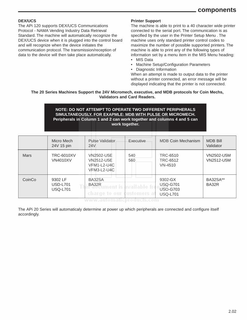
The 20 Series Machines Support the 24V Micromech, executive, and MDB protocols for Coin Mechs,Validators and Card Readers.
NOTE: DO NOT ATTEMPT TO OPERATE TWO DIFFERENT PERIPHERALSSIMULTANEOUSLY. FOR EXAPMLE: MDB WITH PULSE OR MICROMECH.
Peripherals in Column 1 and 2 can work together and columns 4 and 5 canwork together.
Micro Mech Pulse Validator Executive MDB Coin Mechanism MDB Bill24V 15 pin 24V Validator
Mars TRC-6010XV VN2502-U5E 540 TRC-6510 VN2502-U5MVN4010XV VN2512-U5E 560 TRC-6512 VN2512-U5M
VFM1-L2-U4C VN-4510VFM3-L2-U4C
CoinCo 9302 LF BA32SA 9302-GX BA32SA**USD-L701 BA32R USQ-G701 BA32RUSQ-L701 USO-G703
USQ-L701
The APi 20 Series will automaticaly determine at power up which peripherals are connected and configure itselfaccordingly.
2.03
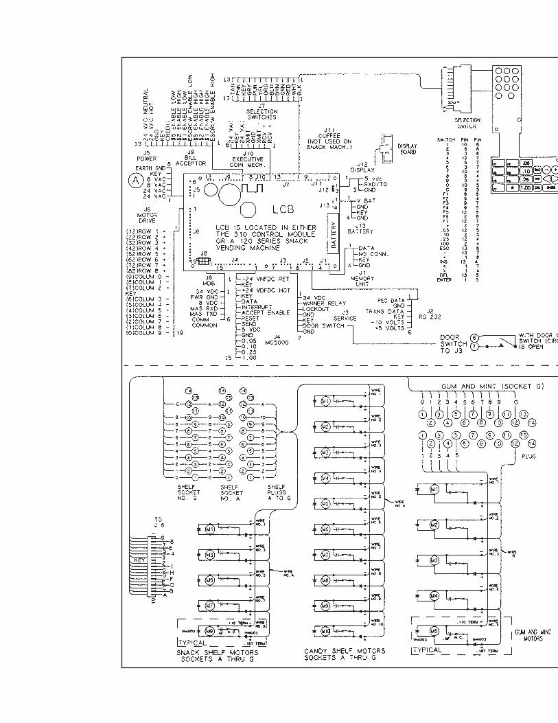
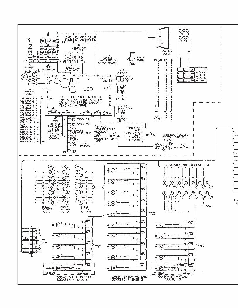
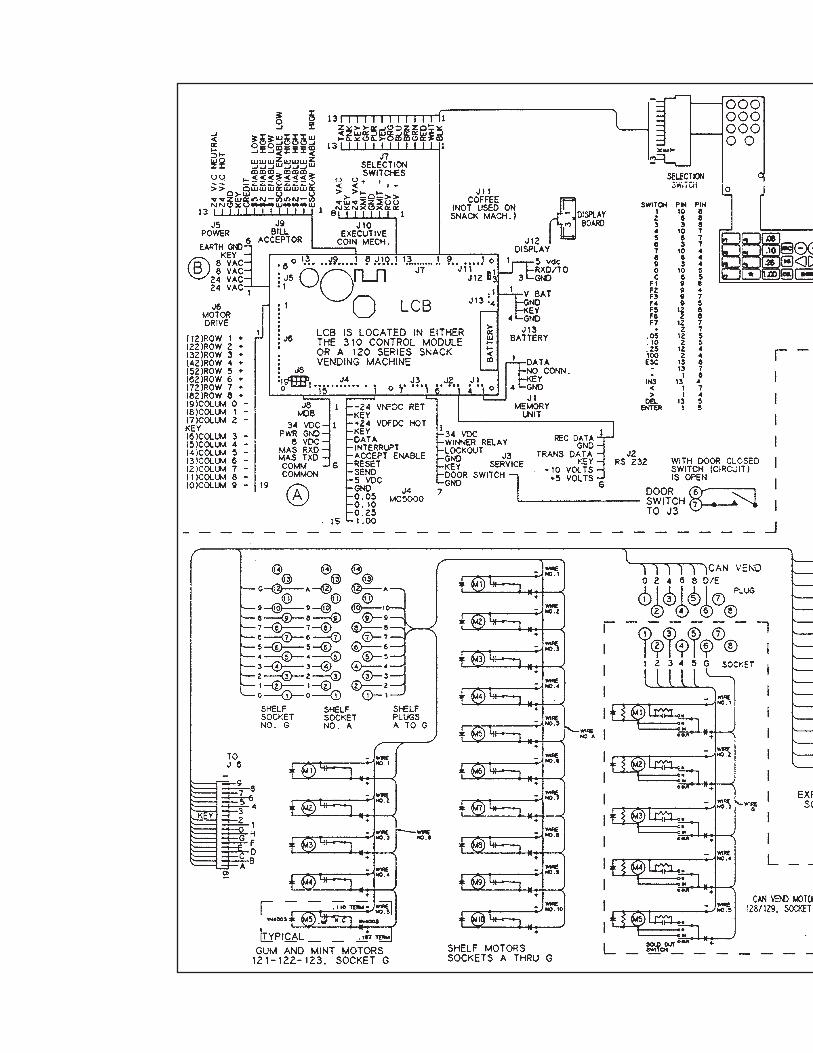
Vend MotorsThe vend motors used in the APi 120 machines have been specifically developed to operate with the APi MasterVend™Control System. One primary difference that distinguishes the new motors from previous motors is the presence of aneight sided star at the drive hub of the motor. This permits the stopping position of the spiral to be customized by theoperator to ensure the best possible delivery of product. Motors used in the 120 & 320 are of the fast trac style, with allelectronics required to correctly operate the motor contained inside the gear case or the motor housing and no externalcontrol board. Each of the motors used with the MasterVend™ Control System will have two terminals. The two terminalscontinue to be used to identify the shelf and column (selection) to be vended.
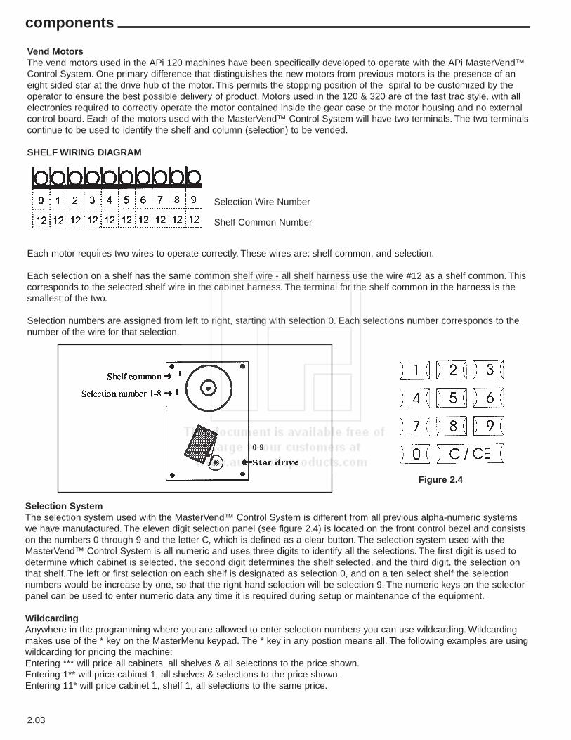
SHELF WIRING DIAGRAM
Each motor requires two wires to operate correctly. These wires are: shelf common, and selection.
Each selection on a shelf has the same common shelf wire - all shelf harness use the wire #12 as a shelf common. Thiscorresponds to the selected shelf wire in the cabinet harness. The terminal for the shelf common in the harness is thesmallest of the two.
Selection numbers are assigned from left to right, starting with selection 0. Each selections number corresponds to thenumber of the wire for that selection.
Selection Wire Number
Shelf Common Number
0-9
components
Selection SystemThe selection system used with the MasterVend™ Control System is different from all previous alpha-numeric systemswe have manufactured. The eleven digit selection panel (see figure 2.4) is located on the front control bezel and consistson the numbers 0 through 9 and the letter C, which is defined as a clear button. The selection system used with theMasterVend™ Control System is all numeric and uses three digits to identify all the selections. The first digit is used todetermine which cabinet is selected, the second digit determines the shelf selected, and the third digit, the selection onthat shelf. The left or first selection on each shelf is designated as selection 0, and on a ten select shelf the selectionnumbers would be increase by one, so that the right hand selection will be selection 9. The numeric keys on the selectorpanel can be used to enter numeric data any time it is required during setup or maintenance of the equipment.
WildcardingAnywhere in the programming where you are allowed to enter selection numbers you can use wildcarding. Wildcardingmakes use of the * key on the MasterMenu keypad. The * key in any postion means all. The following examples are usingwildcarding for pricing the machine:Entering *** will price all cabinets, all shelves & all selections to the price shown.Entering 1** will price cabinet 1, all shelves & selections to the price shown.Entering 11* will price cabinet 1, shelf 1, all selections to the same price.
Figure 2.4
2.04
components
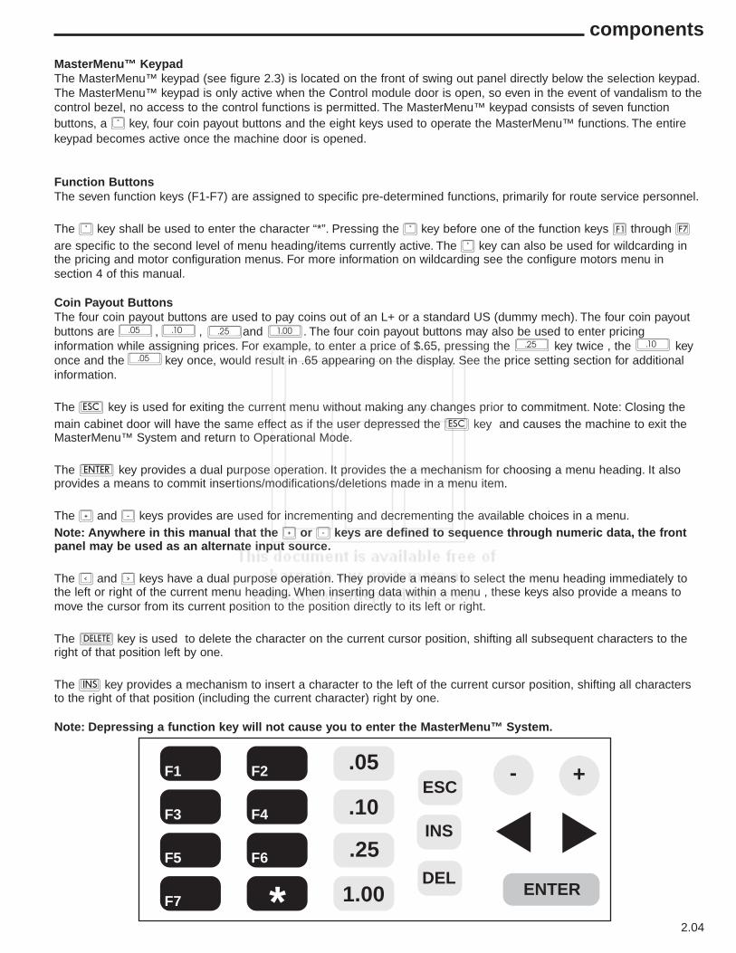
MasterMenu™ KeypadThe MasterMenu™ keypad (see figure 2.3) is located on the front of swing out panel directly below the selection keypad.The MasterMenu™ keypad is only active when the Control module door is open, so even in the event of vandalism to thecontrol bezel, no access to the control functions is permitted. The MasterMenu™ keypad consists of seven functionbuttons, a * key, four coin payout buttons and the eight keys used to operate the MasterMenu™ functions. The entirekeypad becomes active once the machine door is opened.
Function ButtonsThe seven function keys (F1-F7) are assigned to specific pre-determined functions, primarily for route service personnel.
The * key shall be used to enter the character “*”. Pressing the * key before one of the function keys ¡ through ¶are specific to the second level of menu heading/items currently active. The * key can also be used for wildcarding inthe pricing and motor configuration menus. For more information on wildcarding see the configure motors menu insection 4 of this manual.
Coin Payout ButtonsThe four coin payout buttons are used to pay coins out of an L+ or a standard US (dummy mech). The four coin payoutbuttons are , , and . The four coin payout buttons may also be used to enter pricinginformation while assigning prices. For example, to enter a price of $.65, pressing the key twice , the keyonce and the key once, would result in .65 appearing on the display. See the price setting section for additionalinformation.
The s key is used for exiting the current menu without making any changes prior to commitment. Note: Closing themain cabinet door will have the same effect as if the user depressed the s key and causes the machine to exit theMasterMenu™ System and return to Operational Mode.
The e key provides a dual purpose operation. It provides the a mechanism for choosing a menu heading. It alsoprovides a means to commit insertions/modifications/deletions made in a menu item.
The + and - keys provides are used for incrementing and decrementing the available choices in a menu.Note: Anywhere in this manual that the + or - keys are defined to sequence through numeric data, the frontpanel may be used as an alternate input source.
The < and > keys have a dual purpose operation. They provide a means to select the menu heading immediately tothe left or right of the current menu heading. When inserting data within a menu , these keys also provide a means tomove the cursor from its current position to the position directly to its left or right.
The m key is used to delete the character on the current cursor position, shifting all subsequent characters to theright of that position left by one.
The f key provides a mechanism to insert a character to the left of the current cursor position, shifting all charactersto the right of that position (including the current character) right by one.
Note: Depressing a function key will not cause you to enter the MasterMenu™ System.
.05
.05
.10
.10.25
.25
1.00
F1
F3
F5
F7
F2
F4
F6
*
.05
.10
.25
1.00
ESC
INS
DEL
- +
ENTER

2.05
components
Control System and BoardsThe MasterVend™ Control System consists of up to three different boards, depending on the configuration. All Model 120and all towers consist of the LogicCenter board (LCB) and the display board. When a machine is slaved off of the APi120 (320 series 127) this cabinet will have a Food Driver Board (FDB) contained in it.
LogiCenter Board (LCB)The LCB interfaces with the FDB (when used), display board, selector panel, MasterMenu keypad, coin mechs, billvalidators and all other peripherals. The LCB also stores all the programming and mis information.
Food Driver Board (FDB)This board is only used in a food/frozen machine or a slave snack. This board contains all the temperature monitoringfunctions for cabinet that it is contained in, and communicates with the LCB via a 6 wire computer level interconnectharness. The FDB has three LEDs on it and the status of the FDB can be determined by observing the LEDs.
The Front Panel DisplayThe display is capable of displaying 20 alpha-numeric characters. The supported character set includes:
• Upper and lower case alphabetic characters “A” through “Z”• Numeric characters “0” through “9”• Special characters: (, ), [, ], ., ‘, -, =, $, /, \, *, ^, +, , ,”, ?, _.
The ChimeThe chime will sounded when the following events occur:• Three times when an invalid key sequence is entered from either the front panel or the MasterMenu™ Keypad.• Three times when the customer enters an invalid key sequence from the front panel.• Five times when the customer has won a free vend due to WINNER MODE.• For fifteen seconds if a motor configuration mismatch is detected when the main cabinet door is closed.• Five times when the customer attempts to purchase a sold-out item as determined by spiral selection.• A single time to indicate the acceptance of an action by the control system.
2.06
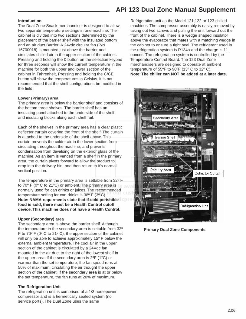
IntroductionThe Dual Zone Snack merchandiser is designed to allowtwo separate temperature settings in one machine. Thecabinet is divided into two sections determined by theplacement of the barrier shelf with the insulated bottomand an air duct Barrier. A 24vdc circular fan (P/N16700018) is mounted just above the barrier andcirculates chilled air in the upper section of the cabinet.Pressing and holding the 0 button on the selection keypadfor three seconds will show the current temperature in themachine for both the upper and lower section of thecabinet in Fahrenheit, Pressing and holding the C/CEbutton will show the temperatures in Celsius. It is notrecommended that the shelf configurations be modified inthe field.
Lower (Primary) areaThe primary area is below the barrier shelf and consists ofthe bottom three shelves. The barrier shelf has aninsulating panel attached to the underside of the shelfand insulating blocks along each shelf rail.
Each of the shelves in the primary area has a clear plasticdeflector curtain covering the front of the shelf. The curtainis attached to the underside of the shelf above. Thiscurtain prevents the colder air in the lower section fromcirculating throughout the machine, and preventscondensation from develoing on the exterior glass of themachine. As an item is vended from a shelf in the primaryarea, the curtain pivots forward to allow the product todrop into the delivery bin, and then return to it’s normalvertical position.
The temperature in the primary area is settable from 32º Fto 70º F (0º C to 21ºC) or ambient. The primary area isnormally used for can drinks or juices. The recommendedtemperature setting for can drinks is 38º F (3º C).Note: NAMA requirments state that if cold perishiblefood is sold, there must be a Health Control cutoffdevice. This machine does not have a Health Control.
Upper (Secondary) areaThe secondary area is above the barrier shelf. Althoughthe temperature in the secondary area is settable from 32ºF to 70º F (0º C to 21º C), the upper section of the cabinetwill only be able to achieve approximately 15º F below theexternal ambient temperature. The cool air in the uppersection of the cabinet is circulated by a 24Vdc fanmounted in the air duct to the right of the lowest shelf inthe upper area. If the secondary area is 2ºF (1°C) orwarmer than the set temperature, the fan speed runs at50% of maximum, circulating the air thought the uppersection of the cabinet. If the secondary area is at or belowthe set temperature, the fan runs at 20% of maximum.
The Refrigeration Unit The refrigeration unit is comprised of a 1/3 horsepowercompressor and is a hermetically sealed system (noservice ports). The Dual Zone uses the same
Refrigeration unit as the Model 121,122 or 123 chilledmachines. The compressor assembly is easily removed bytaking out two screws and pulling the unit forward out thefront of the cabinet. There is a wedge shaped insulatorabove the evaporator that mates with a matching wedge inthe cabinet to ensure a tight seal. The refrigerant used inthe refrigeration system is R134a and the charge is 11ounces. The refrigeration system is controlled by theTemperature Control Board. The 123 Dual Zonemerchandisers are designed to operate at ambienttemperature of 55ºF to 90ºF (13º C to 32º C).Note: The chiller can NOT be added at a later date.
Primary Dual Zone Components
APi 123 Dual Zone Manual Supplement
2.07
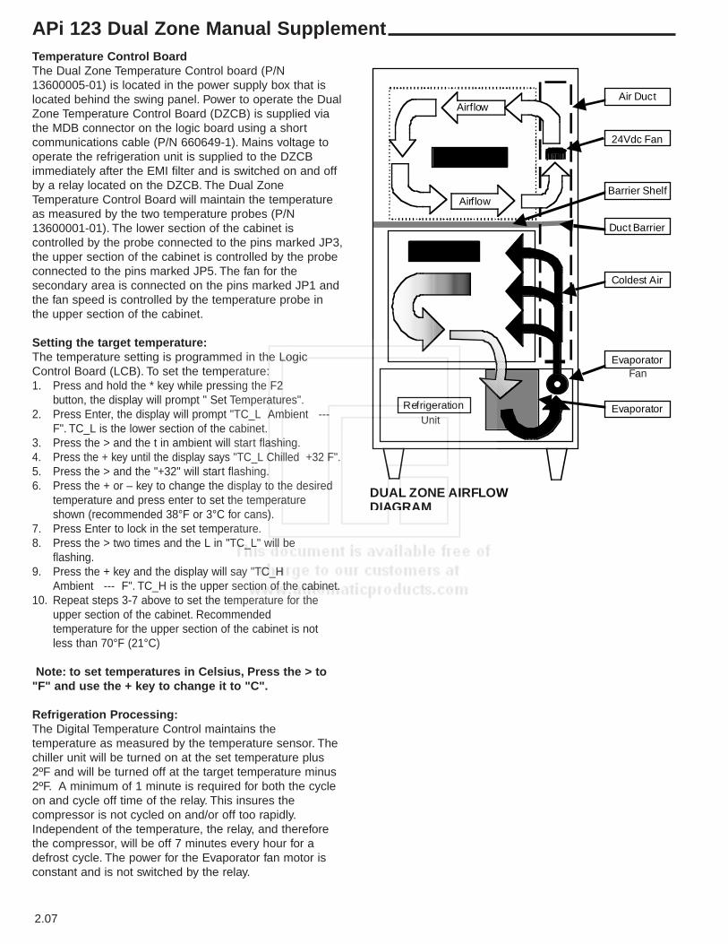
Temperature Control BoardThe Dual Zone Temperature Control board (P/N13600005-01) is located in the power supply box that islocated behind the swing panel. Power to operate the DualZone Temperature Control Board (DZCB) is supplied viathe MDB connector on the logic board using a shortcommunications cable (P/N 660649-1). Mains voltage tooperate the refrigeration unit is supplied to the DZCBimmediately after the EMI filter and is switched on and offby a relay located on the DZCB. The Dual ZoneTemperature Control Board will maintain the temperatureas measured by the two temperature probes (P/N13600001-01). The lower section of the cabinet iscontrolled by the probe connected to the pins marked JP3,the upper section of the cabinet is controlled by the probeconnected to the pins marked JP5. The fan for thesecondary area is connected on the pins marked JP1 andthe fan speed is controlled by the temperature probe inthe upper section of the cabinet.
Setting the target temperature:The temperature setting is programmed in the LogicControl Board (LCB). To set the temperature:1. Press and hold the * key while pressing the F2
button, the display will prompt " Set Temperatures".2. Press Enter, the display will prompt "TC_L Ambient ---
F". TC_L is the lower section of the cabinet.3. Press the > and the t in ambient will start flashing.4. Press the + key until the display says "TC_L Chilled +32 F".5. Press the > and the "+32" will start flashing.6. Press the + or – key to change the display to the desired
temperature and press enter to set the temperature shown (recommended 38°F or 3°C for cans).
7. Press Enter to lock in the set temperature.8. Press the > two times and the L in "TC_L" will be
flashing.9. Press the + key and the display will say "TC_H
Ambient --- F". TC_H is the upper section of the cabinet.10. Repeat steps 3-7 above to set the temperature for the
upper section of the cabinet. Recommendedtemperature for the upper section of the cabinet is not less than 70°F (21°C)
Note: to set temperatures in Celsius, Press the > to"F" and use the + key to change it to "C".
Refrigeration Processing:The Digital Temperature Control maintains thetemperature as measured by the temperature sensor. Thechiller unit will be turned on at the set temperature plus2ºF and will be turned off at the target temperature minus2ºF. A minimum of 1 minute is required for both the cycleon and cycle off time of the relay. This insures thecompressor is not cycled on and/or off too rapidly.Independent of the temperature, the relay, and thereforethe compressor, will be off 7 minutes every hour for adefrost cycle. The power for the Evaporator fan motor isconstant and is not switched by the relay.
Airflow
Airflow
Primary Area
SecondaryArea
Refrigeration
Barrier Shelf
Coldest Air
24Vdc Fan
Duct Barrier
Air Duct
Evaporator
Evaporator
DUAL ZONE AIRFLOWDIAGRAM
Fan
Unit
APi 123 Dual Zone Manual Supplement
3.01
quick set up reference - electronics
The APi 120 machine is shipped with the software already set up, the only setup that is necessary before putting themachine on location is to set the prices.
SET PRICESPress the F4 on the MasterMenu keypad
Press e ’to access SET PRICE menu. <Press > 1 time to price.Using the selection buttons, enter desired price, Calculator style.
Press < 1 time to selection.Using the selection buttons, enter desired selections at the price shownRepeat the above process for all additional prices to be set.
s to exit.
The F 1 - F7 keys on the MasterMenu keypad are preprogrammed to preform a specific function. On the next page youwill find a Copy of the decal on the door of the machine. This decal explains what the function keys are used for as wellas how to use them. For most applications the function keys give you all the options and functionality necessary. Foradvanced set up options see the operating system section of the manual.
3.02
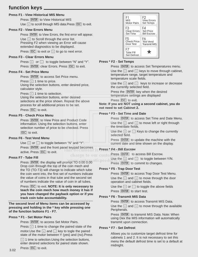
Press F1 - View Historical MIS MenuPress e to View Historical MISUse > to scroll through MlS data.Press s to exit.
Press F2 - View Errors MenuPress e to View Errors, the first error will appear.Use > to Scroll through the error list.Pressing F2 when viewing an Error will cause extended diagnostics to be displayed.
Press s to exit or > to go to next error.
Press F3 - Clear Errors MenuPress + or - to toggle between “N” and “Y”.Press e clear Errors. Press s to exit.
Press F4 - Set Price MenuPress e to access Set Price menu.Press > 1 time to price.Using the selection buttons, enter desired price, calculator style.
Press < 1 time to selection.Using the selection buttons, enter desired selections at the price shown. Repeat the above process for all additional prices to be set.
Press s to exit.
Press F5 - Check Price MenuPress e to View Price and Product Code information. Using the selection buttons, enter selection number of price to be checked. Press
s to exit.
Press F6 - Test Vend MenuUse + or - to toggle between “N” and “Y”.Press e and the front panel keypad becomes active. Press s to exit.
Press F7 - Tube FillPress e the display will prompt TO 0.00 0.00Drop coin through the top of the coin mech andthe TO (TO-T3) will change to indicate which tubethe coin went into, the first set of numbers indicatethe value of coins in that tube and the second setof numbers indicate the value of coin in all tubes.
Press s to exit. NOTE: It is only necessary toteach the coin mech how much money it has ifyou have changed the payback option or if youtrack coin tube accountability.
The second level of Menu items can be accessed bypressing and holding in the * key while pressing oneof the function buttons F1 - F7.
Press * F1 - Set Motor PairsPress e to access Set Motor Pairs.Press > 1 time to change the paired state of the motor.Use the + and - key to togle the paired state of the motor between Y (yes) and (no).Press
< 1 time to selection.Using the selection buttons,enter desired selections for paired state shown.
Press s to exit.
Press * F2 - Set TempsPress e to access Set Temperatures menu.Use the < and > keys to move through cabinet, temperature range, target temperature and temperature scale fields.
Use the + and - keys to increase or decrease the currently selected field.
Press the e key when the desired temperature settings are displayed
Press s to exit.Note: If you are NOT using a second cabinet, you donot need to set Cabinet 2.
Press * F3 - Set Time and DatePress e to access Set Time and Date Menu.Use the < and > to move left or right through the time/date fields.
Use the + or - Keys to change the currently selected field.
Press e to update the machine with the current date and time shown on the display.
Press * F4 - Bill EscrowPress e to access Bill Escrow.Use the + and - to toggle between Y/N.Press e to commit to changes.
Press * F5 - Trap Door TestPress e to access Trap Door Test Menu.Use the < and > to move through the dooroperation and cabinet fields.
Use the + or - to toggle the above fieldsPress e to start test.
Press * F6 - Transmit MIS DataPress e to access Transmit MIS Data.Use the < and > to move through the available Peripherals.
Press e to transmit MIS Data. Note: When using Dex the MIS information will automatically transmit upon connection.
Press * F7 - Set Defrost
Allows you to customize target defrost time for cabinets 1 and 2. It is not necessary to set this menu the default defrost time is set to a default at midnight.
function keys
*
MISMotor Pairs
View ErrorsSet Temps
Clear ErrorsSet Time
Set PriceBill Escrow
Check PriceDoor Test
Test VendTransmit MIS
Tube FillSet Defrost

i
table of contents
TABLE OF CONTENTS
Operating System . . . . . . . . . . . . . . . . . . . . . . . . . . . . . . . . . . . . . . . . . . . . . . . . . . . . . . . . . . . . . . . . . . . . . . . . . . .4.01Operational Mode . . . . . . . . . . . . . . . . . . . . . . . . . . . . . . . . . . . . . . . . . . . . . . . . . . . . . . . . . . . . . . . . . . . . . . . . 4.01Service Mode . . . . . . . . . . . . . . . . . . . . . . . . . . . . . . . . . . . . . . . . . . . . . . . . . . . . . . . . . . . . . . . . . . . . . . . . . . .4.01
MasterMenu™ System . . . . . . . . . . . . . . . . . . . . . . . . . . . . . . . . . . . . . . . . . . . . . . . . . . . . . . . . . . . . . . . . . . . . . . 4.02
Quick Reference Directory for MasterMenu™ . . . . . . . . . . . . . . . . . . . . . . . . . . . . . . . . . . . . . . . . . . . . . . . . . . . . . . 4.03
Mis Menu . . . . . . . . . . . . . . . . . . . . . . . . . . . . . . . . . . . . . . . . . . . . . . . . . . . . . . . . . . . . . . . . . . . . . . . . . . . . . . . . .4.04View MIS Data Menu . . . . . . . . . . . . . . . . . . . . . . . . . . . . . . . . . . . . . . . . . . . . . . . . . . . . . . . . . . . . . . . . . . . . . .4.04Transmit MIS Data Menu . . . . . . . . . . . . . . . . . . . . . . . . . . . . . . . . . . . . . . . . . . . . . . . . . . . . . . . . . . . . . . . . . . .4.05Clear MIS Data Menu . . . . . . . . . . . . . . . . . . . . . . . . . . . . . . . . . . . . . . . . . . . . . . . . . . . . . . . . . . . . . . . . . . . . . 4.07Tube Fill Menu . . . . . . . . . . . . . . . . . . . . . . . . . . . . . . . . . . . . . . . . . . . . . . . . . . . . . . . . . . . . . . . . . . . . . . . . . . 4.07Software Revision . . . . . . . . . . . . . . . . . . . . . . . . . . . . . . . . . . . . . . . . . . . . . . . . . . . . . . . . . . . . . . . . . . . . . . . .4.07
Setup Menu . . . . . . . . . . . . . . . . . . . . . . . . . . . . . . . . . . . . . . . . . . . . . . . . . . . . . . . . . . . . . . . . . . . . . . . . . . . . . . . 4.08Bill Escrow Menu . . . . . . . . . . . . . . . . . . . . . . . . . . . . . . . . . . . . . . . . . . . . . . . . . . . . . . . . . . . . . . . . . . . . . . . . .4.08Free Vend Menu . . . . . . . . . . . . . . . . . . . . . . . . . . . . . . . . . . . . . . . . . . . . . . . . . . . . . . . . . . . . . . . . . . . . . . . . .4.08Winner Vend Menu . . . . . . . . . . . . . . . . . . . . . . . . . . . . . . . . . . . . . . . . . . . . . . . . . . . . . . . . . . . . . . . . . . . . . . .4.08Multiple Vends Menu . . . . . . . . . . . . . . . . . . . . . . . . . . . . . . . . . . . . . . . . . . . . . . . . . . . . . . . . . . . . . . . . . . . . . 4.08Force Vend Menu . . . . . . . . . . . . . . . . . . . . . . . . . . . . . . . . . . . . . . . . . . . . . . . . . . . . . . . . . . . . . . . . . . . . . . . .4.08Combo Vend Menu . . . . . . . . . . . . . . . . . . . . . . . . . . . . . . . . . . . . . . . . . . . . . . . . . . . . . . . . . . . . . . . . . . . . . . .4.08Set Max Payout Menu . . . . . . . . . . . . . . . . . . . . . . . . . . . . . . . . . . . . . . . . . . . . . . . . . . . . . . . . . . . . . . . . . . . . 4.09Set Payout type . . . . . . . . . . . . . . . . . . . . . . . . . . . . . . . . . . . . . . . . . . . . . . . . . . . . . . . . . . . . . . . . . . . . . . . . . .4.09
Configuration Menu Items . . . . . . . . . . . . . . . . . . . . . . . . . . . . . . . . . . . . . . . . . . . . . . . . . . . . . . . . . . . . . . . . . . . . .4.10Motor Pairs . . . . . . . . . . . . . . . . . . . . . . . . . . . . . . . . . . . . . . . . . . . . . . . . . . . . . . . . . . . . . . . . . . . . . . . . . . . . .4.10Configuration Upload/Download Menu . . . . . . . . . . . . . . . . . . . . . . . . . . . . . . . . . . . . . . . . . . . . . . . . . . . . . . . . .4.10Set Temperatures Menu . . . . . . . . . . . . . . . . . . . . . . . . . . . . . . . . . . . . . . . . . . . . . . . . . . . . . . . . . . . . . . . . . . . 4.10Set Function Keys Menu . . . . . . . . . . . . . . . . . . . . . . . . . . . . . . . . . . . . . . . . . . . . . . . . . . . . . . . . . . . . . . . . . . . 4.11Set Spiral Count Menu . . . . . . . . . . . . . . . . . . . . . . . . . . . . . . . . . . . . . . . . . . . . . . . . . . . . . . . . . . . . . . . . . . . . 4.12Printer Setup Menu . . . . . . . . . . . . . . . . . . . . . . . . . . . . . . . . . . . . . . . . . . . . . . . . . . . . . . . . . . . . . . . . . . . . . . .4.12Set Lockout Menu . . . . . . . . . . . . . . . . . . . . . . . . . . . . . . . . . . . . . . . . . . . . . . . . . . . . . . . . . . . . . . . . . . . . . . . 4.12Free Token/Coupon Menu . . . . . . . . . . . . . . . . . . . . . . . . . . . . . . . . . . . . . . . . . . . . . . . . . . . . . . . . . . . . . . . . . .4.12Speech Synthesis Menu . . . . . . . . . . . . . . . . . . . . . . . . . . . . . . . . . . . . . . . . . . . . . . . . . . . . . . . . . . . . . . . . . . .4.12Setup Defrost Menu . . . . . . . . . . . . . . . . . . . . . . . . . . . . . . . . . . . . . . . . . . . . . . . . . . . . . . . . . . . . . . . . . . . . . . .4.12
Diagnostic Menu Items . . . . . . . . . . . . . . . . . . . . . . . . . . . . . . . . . . . . . . . . . . . . . . . . . . . . . . . . . . . . . . . . . . . . . . 4.14View Errors Menu . . . . . . . . . . . . . . . . . . . . . . . . . . . . . . . . . . . . . . . . . . . . . . . . . . . . . . . . . . . . . . . . . . . . . . . .4.14Clear Errors Menu . . . . . . . . . . . . . . . . . . . . . . . . . . . . . . . . . . . . . . . . . . . . . . . . . . . . . . . . . . . . . . . . . . . . . . . 4.14Test Vend Menu . . . . . . . . . . . . . . . . . . . . . . . . . . . . . . . . . . . . . . . . . . . . . . . . . . . . . . . . . . . . . . . . . . . . . . . . . .4.14Motor Test Menu . . . . . . . . . . . . . . . . . . . . . . . . . . . . . . . . . . . . . . . . . . . . . . . . . . . . . . . . . . . . . . . . . . . . . . . . .4.14Baffle Door Test Menu . . . . . . . . . . . . . . . . . . . . . . . . . . . . . . . . . . . . . . . . . . . . . . . . . . . . . . . . . . . . . . . . . . . . 4.14
Security Menu Items . . . . . . . . . . . . . . . . . . . . . . . . . . . . . . . . . . . . . . . . . . . . . . . . . . . . . . . . . . . . . . . . . . . . . . . . 4.15Machine Identification Menu . . . . . . . . . . . . . . . . . . . . . . . . . . . . . . . . . . . . . . . . . . . . . . . . . . . . . . . . . . . . . . . .4.15Serial Number Menu . . . . . . . . . . . . . . . . . . . . . . . . . . . . . . . . . . . . . . . . . . . . . . . . . . . . . . . . . . . . . . . . . . . . . .4.15Password Definition Menu . . . . . . . . . . . . . . . . . . . . . . . . . . . . . . . . . . . . . . . . . . . . . . . . . . . . . . . . . . . . . . . . . 4.15Password Prompt Menu . . . . . . . . . . . . . . . . . . . . . . . . . . . . . . . . . . . . . . . . . . . . . . . . . . . . . . . . . . . . . . . . . . . .4.15Set Security Level Menu . . . . . . . . . . . . . . . . . . . . . . . . . . . . . . . . . . . . . . . . . . . . . . . . . . . . . . . . . . . . . . . . . . . 4.15Machine Reset Menu . . . . . . . . . . . . . . . . . . . . . . . . . . . . . . . . . . . . . . . . . . . . . . . . . . . . . . . . . . . . . . . . . . . . . .4.15Factory Test Menu Item . . . . . . . . . . . . . . . . . . . . . . . . . . . . . . . . . . . . . . . . . . . . . . . . . . . . . . . . . . . . . . . . . . . .4.15

ii
table of contents continued
Time Functions Menu Items . . . . . . . . . . . . . . . . . . . . . . . . . . . . . . . . . . . . . . . . . . . . . . . . . . . . . . . . . . . . . . . . . . .4.16Setting Discount Time of Day and Day of Week Menu . . . . . . . . . . . . . . . . . . . . . . . . . . . . . . . . . . . . . . . . . . . . .4.16Discount Options Menu . . . . . . . . . . . . . . . . . . . . . . . . . . . . . . . . . . . . . . . . . . . . . . . . . . . . . . . . . . . . . . . . . . . 4.16Set Time and Date Menu . . . . . . . . . . . . . . . . . . . . . . . . . . . . . . . . . . . . . . . . . . . . . . . . . . . . . . . . . . . . . . . . . . 4.17Setting Shutdown Time of Day and Day of Week Menu . . . . . . . . . . . . . . . . . . . . . . . . . . . . . . . . . . . . . . . . . . . .4.17Shutdown Options Menu . . . . . . . . . . . . . . . . . . . . . . . . . . . . . . . . . . . . . . . . . . . . . . . . . . . . . . . . . . . . . . . . . . .4.17
Price Menu Items . . . . . . . . . . . . . . . . . . . . . . . . . . . . . . . . . . . . . . . . . . . . . . . . . . . . . . . . . . . . . . . . . . . . . . . . . . 4.18Price Assignment Menu . . . . . . . . . . . . . . . . . . . . . . . . . . . . . . . . . . . . . . . . . . . . . . . . . . . . . . . . . . . . . . . . . . .4.18View Pricing Menu . . . . . . . . . . . . . . . . . . . . . . . . . . . . . . . . . . . . . . . . . . . . . . . . . . . . . . . . . . . . . . . . . . . . . . . 4.18
Display Menu Items . . . . . . . . . . . . . . . . . . . . . . . . . . . . . . . . . . . . . . . . . . . . . . . . . . . . . . . . . . . . . . . . . . . . . . . . 4.19Set Menu Order Menu . . . . . . . . . . . . . . . . . . . . . . . . . . . . . . . . . . . . . . . . . . . . . . . . . . . . . . . . . . . . . . . . . . . .4.19Set Language Menu . . . . . . . . . . . . . . . . . . . . . . . . . . . . . . . . . . . . . . . . . . . . . . . . . . . . . . . . . . . . . . . . . . . . . 4.19Set User Messages Menu . . . . . . . . . . . . . . . . . . . . . . . . . . . . . . . . . . . . . . . . . . . . . . . . . . . . . . . . . . . . . . . . .4.19Set Out of Service Menu . . . . . . . . . . . . . . . . . . . . . . . . . . . . . . . . . . . . . . . . . . . . . . . . . . . . . . . . . . . . . . . . . . 4.20Set After Sale Message Menu . . . . . . . . . . . . . . . . . . . . . . . . . . . . . . . . . . . . . . . . . . . . . . . . . . . . . . . . . . . . . . 4.20
4.01
operating system
IntroductionThe APi MasterMenu™ system is user friendly and provides a common look and feel across all menu items. Thesystem allows the user to move freely through the menus and provides ease of insertion, modification, and deletion ofoperational parameters and data. In addition, the system provides the user with status and diagnostic messages to aid inthe use and service of the machine.
Operational ModeThe Operational mode provides the machine with the ability to vend products. The machine is in Operational Modewhenever the main cabinet door of the machine is closed. Upon opening of the main cabinet door, the
machine will remain in Operational Mode until the e key is depressed at which time it will enter the Service Mode.This allows for vends to occur while the main cabinet door of the machine is open and the userhas not yet entered Service Mode by depressing the e key. This is referred to as Enhanced Operational Mode.Enhanced Operational Mode differs from Operational Mode in that the Function keys and Payout keys are active. If anykey in either of these sets of keys is depressed, it will perform its function and return the machine to EnhancedOperational Mode when complete.
The Service Menu provides access to all configurable items in the machine as well as retrieval of MIS information. TheService Menus shall only be available when the machine is in Service mode.
Service ModeService Mode provides the ability to configure the machine. When the Control Module door is opened, the displayindicates “ENTER FOR MASTERMENU” if no errors have been logged, or “ERRORS-NN” in the case where errors exist(where “NN” is the number of errors). The machine returns to Operational Mode whenever the main cabinet door isclosed.
4.02
mastermenu™ system
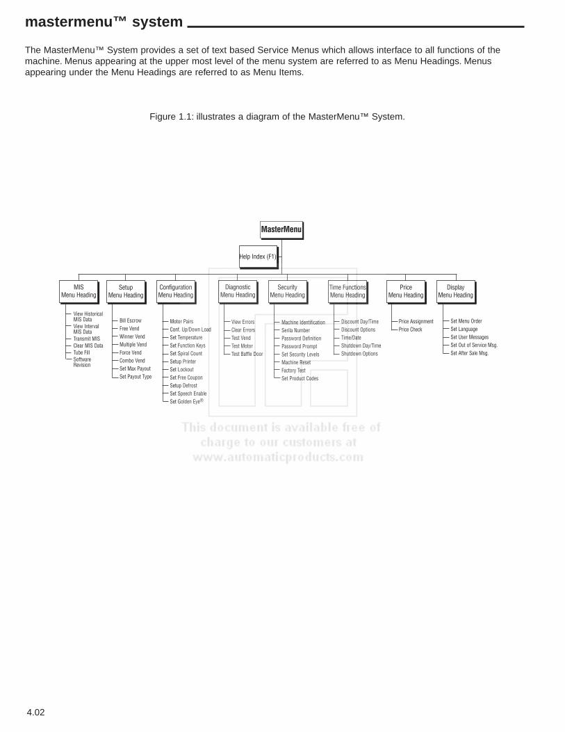
The MasterMenu™ System provides a set of text based Service Menus which allows interface to all functions of themachine. Menus appearing at the upper most level of the menu system are referred to as Menu Headings. Menusappearing under the Menu Headings are referred to as Menu Items.
Figure 1.1: illustrates a diagram of the MasterMenu™ System.
MasterMenu
Help Index (F1)
MISMenu Heading
SetupMenu Heading
ConfigurationMenu Heading
DiagnosticMenu Heading
SecurityMenu Heading
Time FunctionsMenu Heading
PriceMenu Heading
DisplayMenu Heading
View HistoricalMIS DataView IntervalMIS DataTransmit MISClear MIS DataTube FillSoftwareRevision
Bill EscrowFree VendWinner VendMultiple VendForce VendCombo VendSet Max PayoutSet Payout Type
Motor PairsConf. Up/Down LoadSet TemperatureSet Function KeysSet Spiral CountSetup PrinterSet LockoutSet Free CouponSetup DefrostSet Speech EnableSet Golden Eye®
View ErrorsClear ErrorsTest VendTest MotorTest Baffle Door
Machine IdentificationSerila NumberPassword DefinitionPassword PromptSet Security LevelsMachine ResetFactory TestSet Product Codes
Discount Day/TimeDiscount OptionsTime/DateShutdown Day/TimeShutdown Options
Price AssignmentPrice Check
Set Menu OrderSet LanguageSet User MessagesSet Out of Service Msg.Set After Sale Msg.

4.03
quick reference directory for mastermenu™
The following is a quick reference for the keys on the MasterMenu™ keypad, for a detailed list see page 2.05 of thecomponents section.
* Used to enter the character “*”.
The four coin payout buttons may also be used to enter pricing information while assigning prices.
s Used for exiting the current menu without making any changes.
e Used to choose a menu heading and to commit to insertions/modifications/deletions madein a menu item.
< and > Used to move the cursor from its current position to the position directly to its left or right also to select the menu heading immediately to the left of the current menu heading.
+ and - Used for incrementing and decrementing the available choices in a menu .Note: Anywhere in this manual that the + or - keys are defined to sequence through numeric data, the front panel may be used as an alternate input source.
m Used to delete the character on the current cursor position.
f Used to insert a character to the left of the current cursor position.
Note: Depressing a function key will not cause you to enter the MasterMenu™ System.
Operating System Quick Reference IndexOn the bottom of each page is a quick reference index (figure 1.2). The white box indicates where you are in theMasterMenu™ System, the shaded areas can be used as a reference to move through the sections of the manual.Figure 1.2 below indicates that you would be in the diagnostics menu.
Figure 1.2
M I S MENU SETUP MENU CONFIGURATION MENU DIAGNOSTIC MENU SECURITY MENU TIME FUNCTIONS PRICE MENU DISPLAY MENU
.05
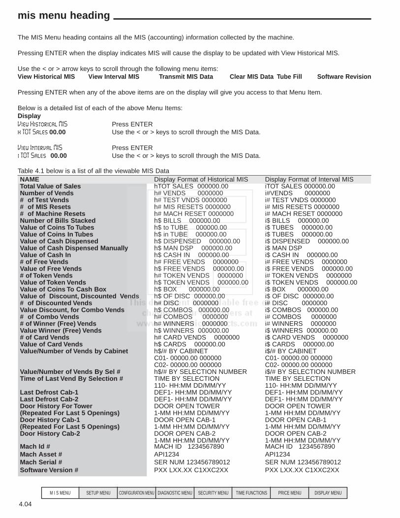
4.04
mis menu heading
M I S MENU SETUP MENU CONFIGURATION MENU DIAGNOSTIC MENU SECURITY MENU TIME FUNCTIONS PRICE MENU DISPLAY MENU
NAME Display Format of Historical MIS Display Format of Interval MISTotal Value of Sales hTOT SALES 000000.00 iTOT SALES 000000.00Number of Vends h# VENDS 0000000 i#VENDS 0000000 # of Test Vends h# TEST VNDS 0000000 i# TEST VNDS 0000000 # of MIS Resets h# MIS RESETS 0000000 i# MIS RESETS 0000000 # of Machine Resets h# MACH RESET 0000000 i# MACH RESET 0000000 Number of Bills Stacked h$ BILLS 000000.00 i$ BILLS 000000.00 Value of Coins To Tubes h$ to TUBE 000000.00 i$ TUBES 000000.00Value of Coins In Tubes h$ in TUBE 000000.00 i$ TUBES 000000.00Value of Cash Dispensed h$ DISPENSED 000000.00 i$ DISPENSED 000000.00Value of Cash Dispensed Manually h$ MAN DSP 000000.00 i$ MAN DSPValue of Cash In h$ CASH IN 000000.00 i$ CASH IN 000000.00# of Free Vends h# FREE VENDS 0000000 i# FREE VENDS 0000000Value of Free Vends h$ FREE VENDS 000000.00 i$ FREE VENDS 000000.00# of Token Vends h# TOKEN VENDS 0000000 i# TOKEN VENDS 0000000Value of Token Vends h$ TOKEN VENDS 000000.00 i$ TOKEN VENDS 000000.00Value of Coins To Cash Box h$ BOX 000000.00 i$ BOX 000000.00 Value of Discount, Discounted Vends h$ OF DISC 000000.00 i$ OF DISC 000000.00 # of Discounted Vends h# DISC 0000000 i# DISC 0000000 Value Discount, for Combo Vends h$ COMBOS 000000.00 i$ COMBOS 000000.00 # of Combo Vends h# COMBOS 0000000 i# COMBOS 0000000 # of Winner (Free) Vends h# WINNERS 0000000 i# WINNERS 0000000 Value Winner (Free) Vends h$ WINNERS 000000.00 i$ WINNERS 000000.00# of Card Vends h# CARD VENDS 0000000 i$ CARD VENDS 0000000 Value of Card Vends h$ CARDS 000000.00 i$ CARDS 000000.00Value/Number of Vends by Cabinet h$/# BY CABINET i$/# BY CABINET
C01- 00000.00 000000 C01- 00000.00 000000C02- 00000.00 000000 C02- 00000.00 000000
Value/Number of Vends By Sel # h$/# BY SELECTION NUMBER i$/# BY SELECTION NUMBERTime of Last Vend By Selection # TIME BY SELECTION TIME BY SELECTION
110- HH:MM DD/MM/YY 110- HH:MM DD/MM/YY Last Defrost Cab-1 DEF1- HH:MM DD/MM/YY DEF1- HH:MM DD/MM/YY Last Defrost Cab-2 DEF1- HH:MM DD/MM/YY DEF1- HH:MM DD/MM/YY Door History For Tower DOOR OPEN TOWER DOOR OPEN TOWER (Repeated For Last 5 Openings) 1-MM HH:MM DD/MM/YY 1-MM HH:MM DD/MM/YY Door History Cab-1 DOOR OPEN CAB-1 DOOR OPEN CAB-1 (Repeated For Last 5 Openings) 1-MM HH:MM DD/MM/YY 1-MM HH:MM DD/MM/YY Door History Cab-2 DOOR OPEN CAB-2 DOOR OPEN CAB-2
1-MM HH:MM DD/MM/YY 1-MM HH:MM DD/MM/YY Mach Id # MACH ID 1234567890 MACH ID 1234567890 Mach Asset # API1234 API1234 Mach Serial # SER NUM 123456789012 SER NUM 123456789012Software Version # PXX LXX.XX C1XXC2XX PXX LXX.XX C1XXC2XX
The MIS Menu heading contains all the MIS (accounting) information collected by the machine.
Pressing ENTER when the display indicates MIS will cause the display to be updated with View Historical MIS.
Use the < or > arrow keys to scroll through the following menu items:View Historical MIS View Interval MIS Transmit MIS Data Clear MIS Data Tube Fill Software Revision
Pressing ENTER when any of the above items are on the display will give you access to that Menu Item.
Below is a detailed list of each of the above Menu Items:DisplayView Historical MIS Press ENTER h TOT Sales 00.00 Use the < or > keys to scroll through the MIS Data.
View Interval MIS Press ENTER i TOT Sales 00.00 Use the < or > keys to scroll through the MIS Data.
Table 4.1 below is a list of all the viewable MIS Data

DisplayTransmit MIS Data Press ENTERTransmit to Dex Use the > to printer or Press ENTER to Transmit to Dex (Dex transfer is automatic on connection
of dex device on software version 3.50 or higher) See table 4.2 for a list of MIS Data transferred and Dex definitions.
Transmit to printer Press ENTER then use the + or – key to toggle between Short list and Full List. Press ENTER to start the print. See table 4.3 for a list of MIS data transferred to the printer.
Table 4.2DEX/UCS DefinitionID1*0987654321*LCB120*3993* * Serial # * Model # * Software Version * Machine Location** Machine ID #API**1234567890 VA1*300*9*300*9 *Total Cash (H) * Total Vends (H) * Total Cash (I) * Total Vends (I) VA2**2**2 ** # Test Vends (H) ** # Test Vends (I)VA3*50*1*50*1 *Value of Winner (free) Vends (H) * Number of Winner (free) Vends (H) *
Value of Winner (free) Vends ( I ) * Number of Winner (free) Vends ( I )TA2***0*0*0*0 *** Value of Token Vends (I) * Number of Token Vends (I)* Value of Token
Vends (H) * Number of Token Vends (H)PA1*CAB1 * Cabinet 1PA2*7*250*7*250 * # of Vends for PA1 above (H) * Value of Vends (H) * # of Vends (I) *
Value of Vends (I)PA1*CAB2 * Cabinet 2PA2*3*150*3*150 * # of Vends for PA1 above (H) * Value of Vends (H) * # of Vends (I) *
Value of Vends (I)CA3*600*0*300*300*600*0*300 *Value of Cash in ( I ) * Value of Cash to box ( I ) * Value of cash to tubes (I)
* Value of bills to box (I) * Value of Cash in (H) * Value of cash to box (H) * Value of Cash to Tubes (H) * Value of Bills to box (H)
CA4*200*540*200*540 Value of Cash Dispensed (I) * Value of Cash Manually Dispensed (I) *Value of Cash Dispensed (H) * Value of Cash Manually Dispensed (H)
CA7*50*50 * Value of Discounts ( I ) * Value of Discounts (H)CA15*0 Value of Coin Tubes DA2*0**0* * Value of Card Sales (H) * Number of Card Sales (H) * Value of Card Sales (I) *
Number of Card Sales (I)EA2*MIS RES**0 *MIS Resets ** # of MIS Resets Since Installation EA2*MACH RES**0 * Machines Resets * # of Machine Resets Since Installation MA5*DISC*1*1 * Discounts * # of Discounts (H) * # of Discounts ( I ) MA5*COMBO*50*1*50*1 * Combo * Value of Combo Vends (H) * # of Discount Vends (H) * Value of
Combo Vends ( I ) * # of Discount Vends ( I )MA5* Winner *50*1*50*1 * Winner * Value of Winner Vends (H) * # of Winner (H) * Value of Winner
Vends (I) * # of Winner Vends (I)LS*0001 * Loop Header (Start of information by selection or product code) PA1*110*20*001*0 (duplicated for * Selection # * Selection Price * Product code * Spiral Countall selections in the machine) PA2*7*250*7*250 (duplicated for * # of Vends for PA1 above (H) * Value of Vends (H) * # of Vends ( I ) *all selections in the machine) Value of Vends ( I )PA5*TIME*020421*1655 * Time of last Vend for PA1 above * YYMMDD * HHMM(duplicated for all selections Note: If date = 000000 Selection is not in use.in the machine)
EA1*M DOOR * Last Time of Door Opening for Tower or Snack * YYMMDD * HHMM * 1*020421*1655*60 (repeated 5 MM, # of Minutes Door was Opentimes for last 5 door openings) EA1*C1 DOOR * Last Time of Door Opening for Cabinet 1 * YYMMDD * HHMM * MM, 1*000000*0000*00 (repeated 5 # of Minutes Door was Opentimes for last 5 door openings) EA1*C2 DOOR * Last Time of Door Opening for Cabinet 2 * YYMMDD * HHMM * MM, 1*000000*0000*00 (repeated 5 # of Minutes Door was Opentimes for last 5 door openings) EA1*DEF 1*000000*0000 * Last Time of Defrost for Cabinet 1 * YYMMDD * HHMM EA1*DEF 2*000000*0000 * Last Time of Defrost for Cabinet 2 * YYMMDD * HHMM
I = Interval vends since last resetH = Historical vends
4.05
mis menu heading
M I S MENU SETUP MENU CONFIGURATION MENU DIAGNOSTIC MENU SECURITY MENU TIME FUNCTIONS PRICE MENU DISPLAY MENU
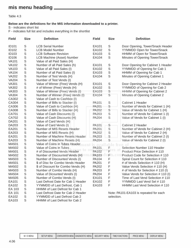
Table 4.3
Below are the definitions for the MIS information downloaded to a printer.S - indicates short listF - indicates full list and includes everything in the shortlist
Field Size Definition Field Size Definition
ID101 S LCB Serial Number EA101 S Door Opening, Tower/Snack HeaderID102 S LCB Model Number EA102 S YYMMDD Open for Tower/SnackID103 S LCB Software Revision EA103 S HHMM of Open for Tower/SnackID106 S LCB Machine (Asset) Number EA104 S Minutes of Opening Tower/SnackVA101 S Value of all Paid Sales (H)VA102 S Number of all Paid Sales (h) EA101 S Door Opening for Cabinet 1 HeaderVA103 S Value of all Paid Sales (I) EA102 S YYMMDD of Opening for Cab 1VA104 S Number of all Paid Sales (I) EA103 S HHMM of Opening for Cab 1VA202 S Number of Test Vends (H) EA104 S Minutes of Opening Cabinet 1VA204 S Number of Test Vends (I)VA301 S Value of Winner (Free) Vends (H) EA101 S Door Opening for Cabinet 2 HeaderVA302 S # of Winner (Free) Vends (H) EA102 S YYMMDD of Opening for Cab 2VA303 S Value of Winner (Free) Vends (I) EA103 S HHMM of Opening for Cabinet 2VA304 S Number of Winner (Free) Vends (I) EA104 S Minutes of Opening Cabinet 2CA302 S Value of Cash to Cashbox (I)CA304 S Number of Bills to Stacker (I) PA101 S Cabinet 1 HeaderCA306 S Value of Cash to Cashbox (H) PA201 S Number of Vends for Cabinet 1 (H)CA308 S Number of Bills to Stacker (H) PA202 S Value of Vends for Cabinet 1 (H)CA701 S Value of Cash Discounts (I) PA203 S Number of Vends for Cabinet 1 (I)CA702 S Value of Cash Discounts (H) PA204 S Value of Vends for Cabinet 1 (I)DA201 S Value of Card Vends (H)DA203 S Value of Card Vends (I) PA101 S Cabinet 2 HeaderEA201 S Number of MIS Resets Header PA201 S Number of Vends for Cabinet 2 (H)EA203 S Number of MIS Resets (H) PA202 S Value of Vends for Cabinet 2 (H)EA201 S Number of Machine Resets Header PA203 S Number of Vends for Cabinet 2 (I)EA203 S Number of Machine Resets (H) PA204 S Value of Vends for Cabinet 2 (I)MA501 S Value of Coins in Tubes HeaderMA502 S Value of Coins in Tubes PA101 F Selection Number 110 Header MA501 S # of Discounted Vends Header PA102 F Product Price Delection # 110MA502 S Number of Discounted Vends (H) PA103 F Product Code for Selection # 110MA503 S Number of Discounted Vends (I) PA104 F Spiral Count for Selection # 110MA501 S $ of Disc for Combo Vends Header PA201 F # of Vends Selection # 110 (H)MA502 S $ of Discount for Combo Vends (H) PA202 F Value Vends Selection # 110 (H)MA503 S Number of Combo Vends (H) PA203 F # of Vends for Selection # 110 (I)MA504 S Value of Dicounted Vend/s (I) PA204 F Value Vends for Selection # 110 (I)MA505 S Number of Combo Vends (I) EA101 F Time of Last Vend Selection # 110EA101 S Last Defrost Date for Cab 1 Header EA102 F YYMMDD Last Vend Sel # 110EA102 S YYMMDD of Last Defrost, Cab 1 EA103 F HHMM Last Vend Selection # 110EA 103 S HHMM of Last Defrost for Cab 1EA 101 S Last Defrost Date for Cab 2 Header Note: PA101-EA103 is repeated for eachEA102 S YYMMDD of Last Defrost Cab 2 selection.EA103 S HHMM of Last Defrost for Cab 2
4.06
mis menu heading
M I S MENU SETUP MENU CONFIGURATION MENU DIAGNOSTIC MENU SECURITY MENU TIME FUNCTIONS PRICE MENU DISPLAY MENU

DisplayClear MIS Data - N Pressing the + key to toggle the N (no) to Y (yes) then press ENTER will reset the interval MIS
data. It will also increase the MIS reset field by 1 reset each time a reset is done.
Tube Fill Allows you to fill the coin mech and the logic board will count the money as it goes in and continually track the coin mech inventory. This is the count the board uses when you choose tube leveling as a Payout type in the Setup menu heading.NOTE: It is not necessary to fill the coin mech in this mode unless you have changed to tube leveling. To proceed press ENTER
TO = 00.00 ( XX.XX TO is the tube # of the last coin inserted (1-4, O for a non tube coin)00.00 is the value of the coins in the tube shown.XX.XX is the value of coins in all tubes.
Software Revision Press ENTERP030 L04.00 C117 C217 P030 is the software version of the Microprocessor on the logic board. ( large chip).
L04.00 is the software version of the Flash Memory chip on the logic board. (small chip).C117 is the software version of the Flash Memory chip on the Food Driver Board (small chip) in cabinet 1.C217 is the software version of the Flash Memory chip on the Food Driver Board (small chip) in cabinet 2.
Setup view MIS Press ENTER and the display will prompt you with the first viewable MIS item:HTOT SALES - Y Use the < or > key to scroll through the list of viewable MIS items. Press the + key to toggle the Y
(yes) to (no) to N (no) if you do not want the item shown to be viewed in the View MIS Menu.When you have finished making changes press ENTER for the changes to take effect.
The MIS data is incremented as follows:
Field Normal Discount Token or Discount & Combo Testvend FreevendWinner Winner Winner or
Token #VENDS • • • • • • $VENDS (Sale Price) • • 0 0 • 0 #/PROD • • • • • •$/PROD (Sale Price) • • 0 0 • 0 #/TESTVEND • #/DISCOUNT • • •$/DISCOUNT (Amount) • • • (List)#/WINNER • • $/WINNER (Sale Price) • • #/COMBO •$/COMBO (Discount) •
• Indicates which field is updated for a given vend type.
(List Price - Discount Amount if any = Sale Price)
Note: $Winner accumulates sale prices of Winners. If the Winner is also Discounted, the vend is counted in #Discountand the discount is accumulated in $Discount.
4.07
mis menu heading
M I S MENU SETUP MENU CONFIGURATION MENU DIAGNOSTIC MENU SECURITY MENU TIME FUNCTIONS PRICE MENU DISPLAY MENU
Vend Type
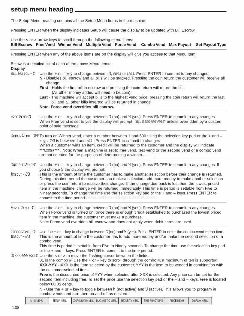
The Setup Menu heading contains all the Setup Menu Items in the machine.
Pressing ENTER when the display indicates Setup will cause the display to be updated with Bill Escrow.
Use the < or > arrow keys to scroll through the following menu items:Bill Escrow Free Vend Winner Vend Multiple Vend Force Vend Combo Vend Max Payout Set Payout Type
Pressing ENTER when any of the above items are on the display will give you access to that Menu Item.
Below is a detailed list of each of the above Menu Items:DisplayBill Escrow - N Use the + or – key to change between N, first or last. Press ENTER to commit to any changes.
N - Disables bill escrow and all bills will be stacked. Pressing the coin return the customer will receive allchange.
First - Holds the first bill in escrow and pressing the coin return will return the bill.(All other money added will need to be coin).
Last - The machine will accept bills to the highest vend price, pressing the coin return will return the lastbill and all other bills inserted will be returned in change.
Note: Force vend overrides bill escrow.
Free Vend-N Use the + or – key to change between N (no) and Y (yes). Press ENTER to commit to any changes.When Free vend is set to yes the display will prompt "all items are free" unless overridden by a custom point of sale message.
Winner Vend -OFF To turn on Winner vend, enter a number between 1 and 500 using the selection key pad or the + and – keys. Off is between 1 and 500. Press ENTER to commit to changes.When a customer wins an item, credit will be returned to the customer and the display will indicate ***winner*** . Note: When a machine is set to free vend, test vend or the second vend of a combo vend are not counted for the purposes of determoning a winner.
Multiple Vend-N Use the + or – key to change between N (no) and Y (yes). Press ENTER to commit to any changes. If you choose Y the display will prompt:
Timeout - 20 This is the amount of time the customer has to make another selection before their change is returned.During this time period the customer can make a selection, add more money to make another selection or press the coin return to receive their change. If the change due back is lest than the lowest priced item in the machine, change will be returned immediately. This time is period is settable from Five to Ninety seconds. To change the time use the selection key pad or the + and – keys. Press ENTER to commit to the time period.
Force Vend - N Use the + or – key to change between N (no) and Y (yes). Press ENTER to commit to any changes.When Force vend is turned on, once there is enough credit established to purchased the lowest priced item in the machine, the customer must make a purchase.Note: Force vend overrides bill escrow and does not apply when debit cards are used.
Combo Vend - N Use the + or – key to change between N (no) and Y (yes). Press ENTER to enter the combo vend menu item.Timeout - 20 This is the amount of time the customer has to add more money and/or make the second selection of a
combo vend.This time is period is settable from Five to Ninety seconds. To change the time use the selection key pad or the + and – keys. Press ENTER to commit to the time period.
01 XXX-YYY Free N Use the < or > to move the flashing cursor between the fields.01 is the combo #. Use the + or – key to scroll through the combo #, a maximum of ten is supportedXXX-YYY - XXX is the item selected by the customer, YYY is the item to be vended in combination with the customer-selected item.Free is the discounted price of YYY when selected after XXX is selected. Any price can be set for the second item including free. To set the price use the selection key pad or the + and – keys. Free is locatedbelow 00.05 cents.N - Use the + or – key to toggle between N (not active) and Y (active). This allows you to program in combo vends and turn then on and off as desired.
4.08
setup menu heading
M I S MENU SETUP MENU CONFIGURATION MENU DIAGNOSTIC MENU SECURITY MENU TIME FUNCTIONS PRICE MENU DISPLAY MENU

Max Payout - N Use the + or – key to change between N (no) and Y (yes). Press ENTER to commit to any changes.
Max Payout - 01.00 When to choose Y the display will show the maximum amount of money to be paid back after a vend. To change the Maximum payback amount use the selection key pad or the + and – keys.Press ENTER to commit to the Maximum payback amount.
Payout - Leveling There are 3 payback options are fewest, MDB level 3 and leveling. Use the + or – key to change between the 3 different options. Press ENTER to commit to a payback option. Here is a discription of the three payback options:Fewest - This option is the factory default and will always payback the least number of coins available based on the sensors in the coin mech.Leveling - The board makes all the payback decisions based on how much money it thinks is in each tube. When using this option it is important that you teach the board how much money is in the coin mech (use "Tube fill" menu item) when you set up the machine.MDB Level 3 - The changer makes all the pay back decisions based up how much money it thinks is in the tubes. This option will only work with MDB coin mechs. All payback options will work with MDB also, you are not limited to this option with MBB coin mechs.
setup menu heading
4.09
M I S MENU SETUP MENU CONFIGURATION MENU DIAGNOSTIC MENU SECURITY MENU TIME FUNCTIONS PRICE MENU DISPLAY MENU
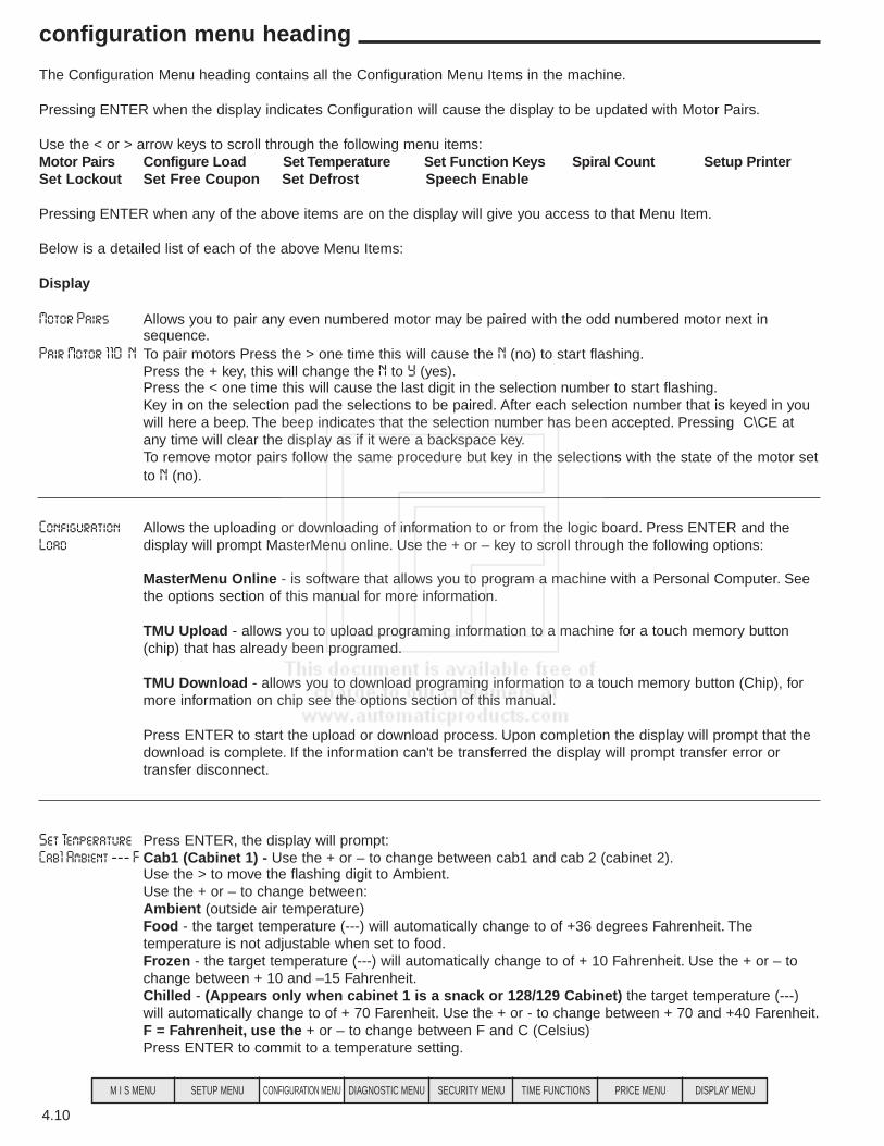
The Configuration Menu heading contains all the Configuration Menu Items in the machine.
Pressing ENTER when the display indicates Configuration will cause the display to be updated with Motor Pairs.
Use the < or > arrow keys to scroll through the following menu items:Motor Pairs Configure Load Set Temperature Set Function Keys Spiral Count Setup PrinterSet Lockout Set Free Coupon Set Defrost Speech Enable
Pressing ENTER when any of the above items are on the display will give you access to that Menu Item.
Below is a detailed list of each of the above Menu Items:
Display
Motor Pairs Allows you to pair any even numbered motor may be paired with the odd numbered motor next insequence.
Pair Motor 110 N To pair motors Press the > one time this will cause the N (no) to start flashing.Press the + key, this will change the N to Y (yes).Press the < one time this will cause the last digit in the selection number to start flashing.Key in on the selection pad the selections to be paired. After each selection number that is keyed in you will here a beep. The beep indicates that the selection number has been accepted. Pressing C\CE at any time will clear the display as if it were a backspace key.To remove motor pairs follow the same procedure but key in the selections with the state of the motor setto N (no).
Configuration Allows the uploading or downloading of information to or from the logic board. Press ENTER and theLoad display will prompt MasterMenu online. Use the + or – key to scroll through the following options:
MasterMenu Online - is software that allows you to program a machine with a Personal Computer. See the options section of this manual for more information.
TMU Upload - allows you to upload programing information to a machine for a touch memory button (chip) that has already been programed.
TMU Download - allows you to download programing information to a touch memory button (Chip), for more information on chip see the options section of this manual.
Press ENTER to start the upload or download process. Upon completion the display will prompt that the download is complete. If the information can't be transferred the display will prompt transfer error or transfer disconnect.
Set Temperature Press ENTER, the display will prompt:Cab1 Ambient --- F Cab1 (Cabinet 1) - Use the + or – to change between cab1 and cab 2 (cabinet 2).
Use the > to move the flashing digit to Ambient.Use the + or – to change between:Ambient (outside air temperature) Food - the target temperature (---) will automatically change to of +36 degrees Fahrenheit. The temperature is not adjustable when set to food.Frozen - the target temperature (---) will automatically change to of + 10 Fahrenheit. Use the + or – to change between + 10 and –15 Fahrenheit.Chilled - (Appears only when cabinet 1 is a snack or 128/129 Cabinet) the target temperature (---) will automatically change to of + 70 Farenheit. Use the + or - to change between + 70 and +40 Farenheit.F = Fahrenheit, use the + or – to change between F and C (Celsius)Press ENTER to commit to a temperature setting.
4.10
configuration menu heading
M I S MENU SETUP MENU CONFIGURATION MENU DIAGNOSTIC MENU SECURITY MENU TIME FUNCTIONS PRICE MENU DISPLAY MENU

Set Function Keys Allows you to change the function keys F1-F7 or F1-*F7 to any of 30 pre defined function keys.Press ENTER and the display will prompt:
F1 - MIS Use the < or > to move the between the function key and the Menu Item.Use the + or – to change the function key or menu item assigned to that key.Press ENTER to commit to any changes.Note: Function keys can be reset to the factory defaults in the machine reset menu item.
The pre-defined functions available for assignment are:
Function Initial Function Key VIEW HISTORICAL MIS F1
VIEW ERRORS F2CLEAR ERRORS F3
SET PRICE F4CHECK PRICE F5
TEST VEND F6 TUBE FILL F7
MOTOR PAIRS *F1SET TEMPERATURE *F2
SET TIME & DATE *F3BILL ESCROW *F4
BAFFLE DOOR TEST *F5 TRASMIT MIS *F6
SETUP DEFROST *F7 WINNER VEND OPEN MULTI VEND OPEN
COMBO VEND OPEN SET MAX PAYOUT OPEN SET PAYOUT TYPE OPEN
SET LOCKOUT OPEN CONFIGURE LOAD OPEN
MOTOR TEST OPEN DISCOUNT DAY / TIME OPEN DISCOUNT OPTIONS OPEN
SHUTDOWN DAY / TIME OPEN SHUTDOWN OPTIONS OPEN SET USER MESSAGES OPEN
OUT OF SERVICE MESSAGE OPEN AFTER SALE MESSAGE OPEN
SET SCROLLING OPEN SET MENU ORDER OPEN SERIAL NUMBER OPEN
4.11
configuration menu heading
M I S MENU SETUP MENU CONFIGURATION MENU DIAGNOSTIC MENU SECURITY MENU TIME FUNCTIONS PRICE MENU DISPLAY MENU
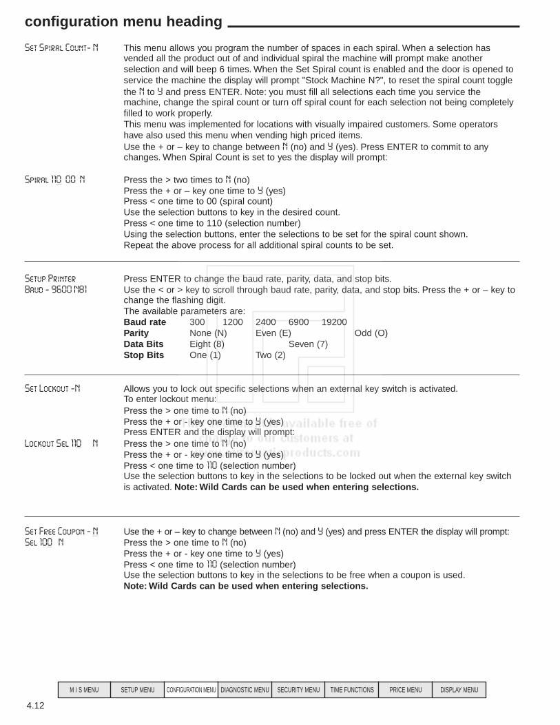
Set Spiral Count- N This menu allows you program the number of spaces in each spiral. When a selection has vended all the product out of and individual spiral the machine will prompt make another selection and will beep 6 times. When the Set Spiral count is enabled and the door is opened to service the machine the display will prompt "Stock Machine N?", to reset the spiral count toggle the N to Y and press ENTER. Note: you must fill all selections each time you service the machine, change the spiral count or turn off spiral count for each selection not being completely filled to work properly.This menu was implemented for locations with visually impaired customers. Some operators have also used this menu when vending high priced items.Use the + or – key to change between N (no) and Y (yes). Press ENTER to commit to any changes. When Spiral Count is set to yes the display will prompt:
Spiral 110 00 N Press the > two times to N (no)Press the + or – key one time to Y (yes)Press < one time to 00 (spiral count)Use the selection buttons to key in the desired count.Press < one time to 110 (selection number)Using the selection buttons, enter the selections to be set for the spiral count shown.Repeat the above process for all additional spiral counts to be set.
Setup Printer Press ENTER to change the baud rate, parity, data, and stop bits.Baud - 9600 N81 Use the < or > key to scroll through baud rate, parity, data, and stop bits. Press the + or – key to
change the flashing digit.The available parameters are:Baud rate 300 1200 2400 6900 19200Parity None (N) Even (E) Odd (O)Data Bits Eight (8) Seven (7)Stop Bits One (1) Two (2)
Set Lockout -N Allows you to lock out specific selections when an external key switch is activated.To enter lockout menu:Press the > one time to N (no)Press the + or - key one time to Y (yes)Press ENTER and the display will prompt:
Lockout Sel 110 N Press the > one time to N (no)Press the + or - key one time to Y (yes)Press < one time to 110 (selection number)Use the selection buttons to key in the selections to be locked out when the external key switch is activated. Note: Wild Cards can be used when entering selections.
Set Free Coupon - N Use the + or – key to change between N (no) and Y (yes) and press ENTER the display will prompt:Sel 100 N Press the > one time to N (no)
Press the + or - key one time to Y (yes)Press < one time to 110 (selection number)Use the selection buttons to key in the selections to be free when a coupon is used.Note: Wild Cards can be used when entering selections.
4.12
configuration menu heading
M I S MENU SETUP MENU CONFIGURATION MENU DIAGNOSTIC MENU SECURITY MENU TIME FUNCTIONS PRICE MENU DISPLAY MENU
Set Defrost Allows you to customize target defrost time for cabinets 1 and 2. It is not necessary to set this menu it is a target defrost time only. Press ENTER ant the display will prompt:
Cab 1 00:00 at 6hrs Press the + or – key to change the flashing digit. Use the < or > key to scroll through the following:Cab1 - Use the + or – key to Toggle between Cab1 (cabinet 1) and Cab2 (cabinet 2).00:00 (midnight) - Is the target time for the defrost cycle. Use the + or – key or the selection key pad to change the target time for the defrost cycle.6hrs - This is the amount of time between defrosts. Use the + or - key to toggle between 6 hours
and 8 hours.Note: Pressing F2 on the keypad will initiate a manual defrost for the cabinet currently being displayed.
Speech Synthesis - N Use the + or – key to change between N (no) and Y (yes). When Y is chosen a Voice Synthesizercan be connected to the DEX/UCS port. The Voice Synthesizer will echo the display while in the service mode.Note: When Speech Synthesis is enabled, the DEX/UCS port can no longer be used for any other communications.
Set Golden Eye - N Use the + or – key to change between N (no) and Y (yes). Pressing Enter when the Y is flashing will enable Golden Eye®.The Display will Prompt: GoldenEye Sel 110 N Press the > one time this will cause the N (no) start flashing.Press the + key, this will change the N toY (yes).Press the < one time this will cause the last digit in the selection number to start flashing.Key in on the selection pad the selection to set to work with Golden Eye®. After each selection number that is keyed in you will here a beep. The beep indicates that the selection number has been accepted. Pressing C\CE at any time will clear the display as if it were a backspace key.Note: Pressing 1** will enable Golden Eye® for the entire machine.To remove selection from working with Golden Eye® follow the same procedure but key in the selections with the state of the motor set to N (no).
4.13
configuration menu heading
M I S MENU SETUP MENU CONFIGURATION MENU DIAGNOSTIC MENU SECURITY MENU TIME FUNCTIONS PRICE MENU DISPLAY MENU
The Diagnostic Menu heading contains all the self-diagnostic capabilities of the machine.
Pressing ENTER when the display indicates Diagnostics will cause the display to be updated with View Errors.
Use the < or > arrow keys to scroll through the following menu items:View Errors Clear Errors Test Vend Test Motors Test Baffle Door
Pressing ENTER when any of the above items are on the display will give you access to that Menu Item.
Below is a detailed list of each of the above Menu Items:DisplayView Errors Pressing ENTER to will cause the first of any pending errors to be displayed. Use the < or > to
sequence through the error list. Pressing F2 when viewing any error will cause the time and the date the error occurred to be shown on the display.
The following lists the possible error codes;
• MOTOR XYZ STALLED • CAB X DEFROST ERROR• MOTOR XYZ STUCK HOME • BAFFLE X CURRENT• MOTOR XYZ DIDNT HOME • BAFFLE X TIMEOUT• MOTOR XYZ OFF HOME • HEALTH SHUTDN CAB X• MOTOR XYZ MISSING
Clear Errors - N Use the + or – key to change between N (no) and Y (yes). Pressing ENTER, when set to Y will cause all errors to be cleared.
Test Vend - N Use the + or – key to change between N (no) and Y (yes). Pressing ENTER, when set to Y will cause the display to prompt:
Test Vend Active The Selection buttons will become active allowing test vends. Closing the door will automatically turn Test Vend off.
Test Motors Press ENTER will prompt:Test Motor - 110 Key in any selection number to be tested. To test the entire cabinet key in 1** for cabinet 1, or 2**
for cabinet 2. The test will show Motor XXX Passed /Failed for 3 seconds for every selection tested. This is a motor detection test and does not vend the motor.
Test Baffle Doors Pressing ENTER will cause the display to prompt:Open door - Cab1 Use the < or > arrow to move between Open Door and Cab1.
Open Door - Use the + or – to toggle between open door and close door.Cab1 - Use the + or – to toggle between Cab1 (cabinet 1) and Cab2 (cabinet 2).Pressing ENTER will cause the baffle door to perform the test shown on the display.
4.14
diagnostic menu heading
M I S MENU SETUP MENU CONFIGURATION MENU DIAGNOSTIC MENU SECURITY MENU TIME FUNCTIONS PRICE MENU DISPLAY MENU
Pressing ENTER when the display indicates Security will cause the display to be updated with Machine ID.Use the < or > arrow keys to scroll through the following menu items:Machine ID Serial Number Password Definition Password Prompt Set Security LevelsSet Product Codes Machine ResetPressing ENTER when any of the above items are on the display will give you access to that Menu Item.Below is a detailed list of each of the above Menu Items:DisplayMachine Id Press ENTER to assign a machine ID number.1234567890 Use the selection keypad to enter a Machine ID number up to 10 digits long.
Press ENTER to commit to any changes.Serial Number Press ENTER to assign a machine Serial number.0987654321 Use the selection key pad to enter a Serial number up to 10 digits long.
Press ENTER to commit to any changes.Password Definition The four levels of security they are:
SuperUser - highest security levelLevel 1 - SuperUser and level 1 have accessLevel 2 - SuperUser , level 1 and level 2 have accessLevel 3 - this is the lowest level of security and no password can be assigned.Press ENTER to change the factory passwords to custom passwords. The display will Prompt:
Password 2 2222 Use the < or > arrow to move between the security level and the password.The + or – key will toggle the flashing digit or use the selection keypad to change the numeric digits. Press ENTER to commit to the password for the security level shown on the display.
Password Prompt - N Use the + or – key to change between N (no) and Y (yes). Pressing ENTER, when set to Y will cause the password prompt to be displayed as soon as the user attempts to press ENTER. If thepassword prompt is set to N (no) and menu items have been assigned security levels, the user must know to press ENTER, then escape to get the password prompt to appear on the display.
Set Security Level - N This menu allows you to set a Security Level for each Menu Heading and Menu Item. Note:Setting a Menu Heading to a Security Level will also hide all Menu Items under the Menu Heading.The four levels of security they are:SuperUser (S) - highest security level.Level 1 - SuperUser and level 1 have access.Level 2 - SuperUser, level 1 and level 2 have access.Level 3 - this is the lowest level of security and no password can be assigned.Use the + or – key to change between N (no) and Y (yes). Pressing ENTER, when set to Y will cause the display to prompt:
MIS 3 MIS - Is the first Menu heading. Use the < or > to scroll through the Menu Headings and Menu Items.3 - is the current security level for the Menu Heading or Menu Item shown on the display. Use the+ or – keys to change the security level. Press ENTER to commit to security level changes.
Factory Test - N Use the + or – key to change N (no) to Y (yes) & press ENTER to test all spirals in the machine.The machine will begin to vend all spirals in sequence. If a motor is not present or bad the machine will beep three times and display the bad motor. To continue with the test press ENTER.
Product Codes - Manual This menu allows you to choose the format the DEX/UCS information is transferred.Use the + or – key to change between Manual & Auto, press ENTER to Set.Manual - The DEX/UCS information is transferred by Product Code.Product Codes can be assigned to a selection or number of selections. See Price setting instructions for details on manually setting product codes.Auto - The DEX/UCS information is transferred by selection (How many times each selection was vended).
Machine Reset - N This menu allows you to reset the machine. The Four Reset options are as follows:Messages - Resets all messages back to factory defaults.Options - Resets all set up options to factory defaults.MIS Data - Resets all MIS (accountability) data, interval and historical to zero.F Keys - Resets all the function keys F1-F7 and *F1-*F7 to factory defaults.All - Resets the entire board to the factory defaults of software in the board.Use the + or – key to change between N (no) and Y (yes). Pressing ENTER, when set to Y will cause the display to prompt:
Reset - MIS Use the + or – key to change between the five reset options. Press ENTER to commit to the reset option.The display will prompt:
Are you Sure - N Use the + or – key to change N (no) to Y (yes) & press ENTER to commit to a reset.
4.15
security menu heading
M I S MENU SETUP MENU CONFIGURATION MENU DIAGNOSTIC MENU SECURITY MENU TIME FUNCTIONS PRICE MENU DISPLAY MENU

The Time Functions Menu Heading contains all the programmable time functions in the machine.
Pressing ENTER when the display indicates Time function will cause the display to be updated with Set Discount Times.
Use the < or > arrow keys to scroll through the following menu items:Set Discount Times Set Discount Options Set Time / Date Set Shutdown Times Set Shutdown Options
Pressing ENTER when any of the above items are on the display will give you access to that Menu Item.
Below is a detailed list of each of the above Menu Items:Display
SET Discount times Press ENTER, the display will prompt:Disc 01 00:00-00:00 Disc 01 is the Discount period. You can set up to 10 different Discount periods. The < or > arrow
keys will change which digit is flashing and the + or – key will toggle the flashing digit.00.00-00.00 is the time settings for the Discount. The number on the left is the time the Discount will start. The second number is the time the machine resumes normal pricing. 00.00 is midnight and all times must to be set in Military time. The times set can not be set to cross over midnight, if you are setting a machine to be Discount all night long you will need to set two Discount periods.Example: If a machine is to be Discounted from 7PM to 7AM the two Discount periods would be set as follows: Disc 01 19:00-23:59 Disc 02 00:00-07:00
Pressing ENTER when viewing a Discount will change the display to:"SMTWTFS" Uppercase letters indicate that the Discount will be active that day.
The < or > arrow keys will change which digit is flashing and the + or – key will toggle the flashing digit between uppercase and lowercase. Pressing ENTER will apply the days of the week as they are currently set on the display.Example: sMTWTFs = Monday through Friday the machine will Discount, Saturday and Sunday the machine will not Discount.
When all discount times are set:a. Press ESC to Exit back to the Menu item Set Discount Times.b. Press the > key one time to:
Set Discount Options Press ENTER. The Display will prompt:Discount Items 01 0.00 N 01 is referring to Discount period 1 programmed above.
0.00 is the amount of discount for all items selected for discount period 01 (example 0.05 will reduce a 0.50 cent item to 0.45 cents.the N (no) or Y (yes) indicated the current status of Discount period 1. Use the + or - keys to toggle between N and Y. Press “ENTER” the display will prompt:
01 Discount - 110 N Press the > one time to N (no)Press < one time to 110 (selection number)Use the selection buttons to key in the selections to be dicounted when the discount period above is activated. Note: Wild Cards can be used when entering selections.
4.16
time functions menu heading
M I S MENU SETUP MENU CONFIGURATION MENU DIAGNOSTIC MENU SECURITY MENU TIME FUNCTIONS PRICE MENU DISPLAY MENU

Set Time/Date Press Enter to set the time and date. The Display will prompt.13:10 18,Jan, 00 13:10 (1:10 PM) is the current time, all times are in military time.
18, Jan, 00 is the 18th day of January 2000.The < or > arrow keys will change which digit is flashing and the + or – key will toggle the flashing digit or use the selection keypad to change the numeric digits. Press ENTER to commit to the time shown on the display.
SET Shutdown TIMES Press ENTER, The display will prompt:Shut 01 00:00-00:00" Shut 01 is the Shutdown period. You can set up to 10 different Shutdown periods. The < or >
arrow keys will change which digit is flashing and the + or - key will toggle the flashing digit.00.00-00.00 is the time settings for the Shutdown. The number on the left is the time the Shutdown will start and the machine will be disabled. The second number is the time the machine will turn back on. 00.00 is midnight and all times must to be set in Military time. The times set can not be set to cross over midnight, if you are setting a machine to be Shutdown all night long you will need to set two Shutdown periods.Example: If a machine is to be Shutdown from 7PM to 7AM the two Discount periods would be set as Follows: "SHUT 01 19:00-23:59 SHUT 02 00:00-07:00
Pressing ENTER when viewing a Shutdown will change the display to:SMTWTFS Upper case letters indicate that the Shutdown will be active that day.
The < or > arrow keys will change which digit is flashing and the + or – key will toggle the flashing digit between uppercase and lowercase. Pressing ENTER will apply the days of the week as they are currently set on the display.Example: sMTWTFs = Monday through Friday the machine will Shutdown, Saturday and Sunday the machine will not Shutdown.
When all Shutdown times are set:a. Press ESC to Exit back to the Menu item Set Shutdown Times.b. Press the > key one time to:
SET SHUTDOWN OPTIONS Press ENTER. The Display will prompt.SHUTDOWN ITEMS 01 N ITEMS 01 is referring to Shutdown period 1 programmed above.
The N (no) or Y (yes) indicates the current status of Shutdown period 1. Use the + or – keys to toggle between N and Y. Press ENTER, the display will prompt:Note: If you are in a school and want to turn off the Shutdown feature for the summer and leave the times programmed, you can do this by changing the current status to N.
01 Shutdown -110 N Press the > one time to N (no)Press the + or - key one time to Y (yes)Press < one time to 110 (selection number)Use the selection buttons to key in all selections to be shutdown for the shutdown period above.Wild Cards can be used when entering selections.
NOTE: The Selections to be Shutdown must be selected for each Shutdown period.If all selections are to be Shutdown, the display will prompt machine not available until the time the machine is programmed to turn back on. If only specific selections are to be Shutdown the display will prompt Selections ............. (Selection numbers) ...... not available until whatever time it is programmed to turn back on.
4.17
time functions menu heading
M I S MENU SETUP MENU CONFIGURATION MENU DIAGNOSTIC MENU SECURITY MENU TIME FUNCTIONS PRICE MENU DISPLAY MENU

The Price Menu Heading contains all the pricing functions in the machine.
Pressing ENTER when the display indicates Price will cause the display to be updated with Price Assignment.
Use the < or > arrow keys to scroll through the following menu items:Price Assignment Check Prices
Pressing ENTER when any of the above items are on the display will give you access to that Menu Item.
Below is a detailed list of each of the above Menu Items:Display
PRICE ASSIGNMENT Press ENTER to set prices, the display will prompt:110 00.50 001 110 - is the selection number, 00.50 - is the price, 001- is the product code.
Press the > one time to price, use the selection buttons key in the price to be set.Note: if you are using product codes press the > one more time to price, use the selectionbuttons key in the product code to be set.Press the < back to the selection number, use the selection buttons key in selections to set at the price and product code shown.Repeat the above process for all prices to be set.
CHECK PRICES Press ENTER to check prices currently set the display will prompt:110 00.50 001 Use the selection buttons to key in a selection number, the current price and product code will
appear on the display.
4.18
price menu heading
M I S MENU SETUP MENU CONFIGURATION MENU DIAGNOSTIC MENU SECURITY MENU TIME FUNCTIONS PRICE MENU DISPLAY MENU
The Display Menu Heading provides access to all the Display Menu Items in the machine.
Pressing ENTER when the display indicates Display will cause the display to be updated with Set Menu Order.
Use the < or > arrow keys to scroll through the following menu items:Set Menu Order Alt Language Set User Messages Set Out of Service Message Set After Sale Message
Pressing ENTER when any of the above items are on the display will give you access to that Menu Item.
Below is a detailed list of each of the above Menu Items:
DisplaySET MENU ORDER This menu allows you to change the order that the Menu Headings appear on the display.
Press ENTER the display will prompt:MENU 1 - mis Use the < or > keys to move between the Menu number and the Menu Heading. Use the + or –
key to scroll through the available menus or to change the menu number.Press ENTER to commit to changes in the menu order.
ALT LANGUAGE - N This menu allows you to use an alternate language for all messages. Use the + or – key to toggle between Y and N.N - indicates all messages will be shown in English.Y - Indicates all messages will be shown in the alternate language programmed by MasterMenu Online.Press ENTER to commit to any changes.
SET USER MESSAGE Use this menu to program up to three different user messages. Press ENTER and the display will prompt:
POS-F EDIT Use the < or > keys to move between the fields.Use the + or – key to toggle between:POS-F, POS-A, POS-B and POS-C.POS-F stands for the factory message; this message is not changeable.POS-A/B/C are the three messages that can be programmed.Pressing the ENTER key when the display prompts POS-A Edit allows you to program message A. The display will prompt:
USER MESSAGE # 1 Note: this is a two step process, first you need to Edit (program) a message (s) then you need to set the message to be active.To Edit the current message:Use the + or – keys to scroll through the Upper and Lower case letters, the numbers 0-9 and a number of special characters including a blank space. Use the <or> to move the flashing cursor to the left or right. Start your message by overwriting the current message (User Message #1).Pressing the INS (insert) key will allow you to insert a character to the left of the flashing digit.Pressing the Del (delete) key will delete the flashing character. When the message is complete
press ENTER. There is no start or end character required. Note: this message will be stored and must be set for the message to become active.
To Set a Message:
POS-A SET Use the + or – key to toggle the display to the message to be set (F, A, B or C).Press the > one time and the T in the word edit will start flashing.Press the + or – key one tome and the word set will appear.Press ENTER and the POS message shown will be set.Note: if the message contains more characters than can be shown on the display the display will scroll. If the message is shorter than the display and you still want it to scroll you need to add blank spaces to the end of the message until the message starts to run off the display.
4.19
display menu heading
M I S MENU SETUP MENU CONFIGURATION MENU DIAGNOSTIC MENU SECURITY MENU TIME FUNCTIONS PRICE MENU DISPLAY MENU

SET OUT OF SERVICE This menu allows you to set an out of service message. The out of service message is added onto the end of the machines out of service message.Press ENTER and the display will go blank with a flashing cursor.Use the + or – keys to scroll through the Upper and Lower case letters, the numbers 0-9 and a number of special characters including a blank space. Use the <or> to move the flashing cursor to the left or rightPress ENTER and the Out of Service message shown will be set.
SET AFTER SALE MESSAGE This menu allows you to set an After Sale Message. Start your message by overwriting the current message(Thank You Very Much).Press ENTER and the display will prompt:
THANK YOU VERY MUCH Use the + or – keys to scroll through the upper and lower case letters, the numbers 0-9 and a number of special characters including a blank space. Use the <or> to move the flashing cursor to the left or right.Press ENTER and the After Sale Message shown will be set.
4.20
display menu heading
M I S MENU SETUP MENU CONFIGURATION MENU DIAGNOSTIC MENU SECURITY MENU TIME FUNCTIONS PRICE MENU DISPLAY MENU
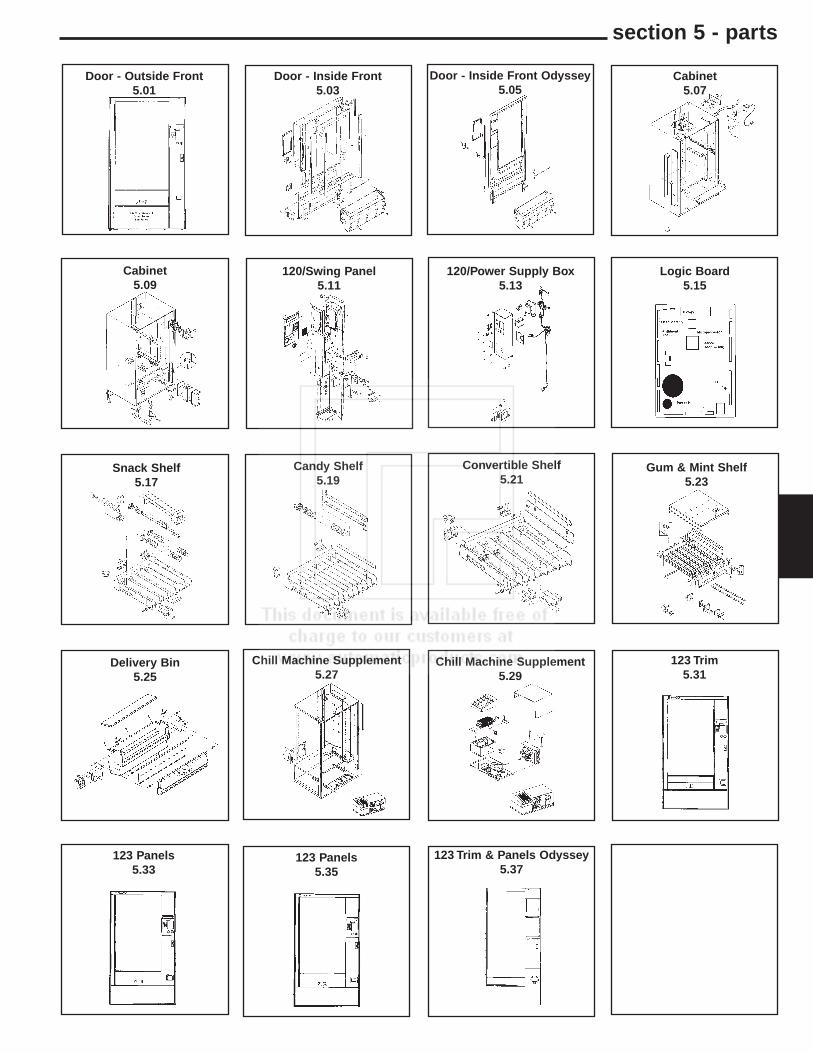
section 5 - parts
Door - Outside Front5.01
Door - Inside Front5.03
Cabinet5.07
Cabinet5.09
120/Swing Panel5.11
120/Power Supply Box5.13
Logic Board5.15
Snack Shelf5.17
Candy Shelf5.19
Convertible Shelf5.21
Gum & Mint Shelf5.23
Delivery Bin5.25
Chill Machine Supplement5.27
Chill Machine Supplement5.29
123 Trim5.31
123 Panels5.33
123 Panels5.35
Door - Inside Front Odyssey5.05
123 Trim & Panels Odyssey5.37

5.01
door - outside front
20
4
14
5.33 - 5.37

ItemNo. Part No. Description
ItemNo. Part No. Description
5.02
door - outside front
ItemNo. Part No. Description
1 340044-9 Top Trim Vantage2 201690-2 Top Trim Insert, True Grit Black.
201690-15 Top Trim Insert, Dark Gray.
3 340057-2 Trim Outside Vertical, Black, Right & Left.
4 202059-52 Panel, Left Side Vertical, Sterling Royce202059-48 Panel, Left Side Vertical, White.202059-50 Panel, Left Side Vertical, Dove Gray.202059-50 Panel, Left Side Vertical, Painted.
5 340058-46 Window Trim, Vertical, Black.6 750141 Front Window (44 5/8 X 26 7/8 X 1/8).
Note: Replacement Glass Must be Hard Tempered or Lexan Only.
750141-8 Thermal Window, Optional (Can only be used on a machine ordered from the factory with a thermal window installed.
7 340058-5 Window Trim, Horizontal, Black.8 201356-1 Deliver Tray Panel, True Grit Black.
201356-43 Deliver Tray Panel, Dark Gray.9 640154 Assembly, Lower Door Hinge Plate. Specify
Color.10 201678 Bottom Door Edging.11 420186 Screw, Pan head 12 201692-1 Lower Horizontal Panel, Black.
201692-56 Lower Horizontal Panel, Gray.13 660581 Coin Cup Front Assembly, Black.
660581-1 Coin Cup Front Assembly, Gray.201156 Coin Cup Door.440411 Coin Cup Trim Only, Black.440411-1 Coin Cup Trim Only, Gray.
14 202805-9 Panel, Right Side Vertical, Lower, Sterling Royce.
202805-49 Panel, Right Side Vertical, Lower, White.202805-43 Panel, Right Side Vertical, Lower, Dove Gray.202805-15 Panel, Right Side Vertical, Lower, Painted.
15 420071 Ace Lock W/2 Keys.16 16600254 Assembly, Lock Handle W Arm & Nut.
17200002 Lock Handle Only.17 440444-2 Bezel Ring, Black.18 600810 Door Only, Specify Color.
600811 Door Only, European Specify Color.600810-1 Door Only, with Validator and Card Reader
Cut Out. Specify Color.600811-1 Door Only Euro With Validator and Card
Reader Cut Out.19 201678-6 Top Door Edging.
20 202806-61 Panel, Right Side Vertical Upper, White.202806-55 Panel, Right Side Vertical Upper, Dove Gray.202806-19 Panel, Right Side Vertical Upper, Painted.202806-13 Panel, Right Side Vertical Upper, Sterling
Royce.750202 Point of Sale Add ON Kit (Not Shown)
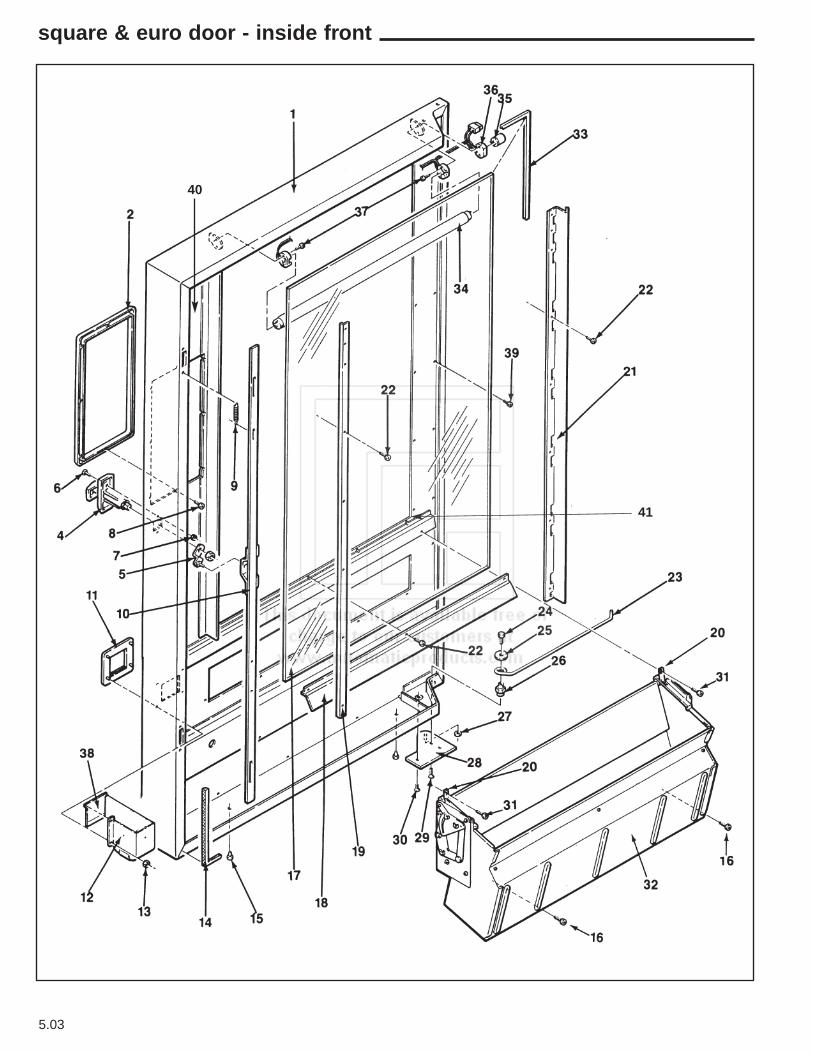
5.03
square & euro door - inside front
40
41

ItemNo. Part No. Description
ItemNo. Part No. Description
5.04
door - inside front
ItemNo. Part No. Description
1 600810 Door Only. Specify Color. (Square)600811 Door Only. European Style. Specify Color.600810-1 Door Only. With Validator Hole And Debit Card
Use. Specify Color. N/A at time of printing.600811-1 Door Only European Style with Validator and
Debit Card Hole
2 440444-2 Trim Ring . Black.440444-3 Bezel Ring. Gray.
4 660319 T-Handle & Lock Arm Assembly. Chrome16600254 T-Handle & Lock Arm Assembly. Brushed420146 T-Handle Only w/Nut. Chrome17200002 T-Handle Only w/Nut. Brushed
5 640131 T-Handle Lock Arm.6 118-10-8 Carriage Bolt #10-24.7 404-10 Nut, Hex #10-24.8 116-6R4 Screw Pan HD. Phil. Type 23. #6-32x1/4.9 400112 Lock Bar Spring.10 600432-3 Lock Bar Assembly11 440411 Coin Cup Trim. Black.
440411-1 Coin Cup Trim. Gray660581 Coin Cup Front Assembly, Black. Includes Trim,
Door, Pin & Spring660581-1 Coin Cup Front Assembly, Gray. Includes Trim,
Door, Pin & Spring300212 Pivot Pin, Coin Cup Door Spring
12 202810 Coin Return Cup660863 Coin Return Cup with Stricker202432 Striker, Door Switch Export300184 Shoulder Bushing Export276-8R6 Screw, Pan HD Self Tap (8-32 X 3/8)(2)
Spring, Striker Door Switch13 420144 Ferrule.13A 305-8R6 Screw14 460041 Door Gasket Foam 1/4 x 1/4. 163” Required15 420040-9 Hole plug.16 276-8R6 Screw, Pan Hd. Phil. Type 23# 8-32x3/8.17 750141 Front Window. (44-5/8 x 26-7/8 x 1/8)
NOTE: Replacement Glass Must Be Hard Tempered or Lexan Only.
750141-8 Thermal window, optional (can only be used ona machine ordered from the factory with a thermal window installed)
460570 Decal. “COOL - COOL” (not shown).18 201384 Bottom Window Clamp.19 202118 Window Clamp. Lock Side.
12000056 Thermal Window Clamp20 200906 Bin Anchor Strap.21 201381-3 Shield & Window Clamp. Pivot Side.22 201-6R11 ScrewRD. HD. Phillips Type B #6 x 11/16.23 400090 Door Stop.
400192 Chilled Machine Door Stop24 114-41-8 Screw Hex. HD. Cap 1/4-20 x 1/ 2.25 420010-10 Washer 1 1/8 OD.26 300156 Door Stop Anchor.27 420010-18 Washer, Brass (Door Adjustment).28 640154 Lower Door Hinge Plate Assembly. Specify Color.29 420003 Flat Head Socket Screw. 3/4 Lg.30 420003-1 Flat Head Socket Screw. 1/2 Lg.31 217-8R10 Screw. Pan Head, Phillips Type B #8 x 5/8.32 Delivery Bin . Assembly Complete.
See Page #5.25 For Itemized Parts.
33a 460436 Window Edging (Order Per Inches). 143 Total.33b 13300007 Thermal Window Edging.34 380022-5 Fluorescent Lamp F18T8/CWK24.
380023-4 Starter FSII 240 volt35 380023 Starter FS-25.36 680512 Lamp Harness Assembly.37 420062-1 Screw Round Head Slot Mach. #4-36 x 3/4.38 440412 Coin Cup Door.39 2016R7 Trim Screws. Screw Rd. Hd.
Phillips Type A (6-18 x 3/8).
200-6R6 Trim Screws. Screw Rd. Hd.Phillips Type A (6-18 x 3/8).
40 460756 Decal Function Keys41 300206 Window Screw
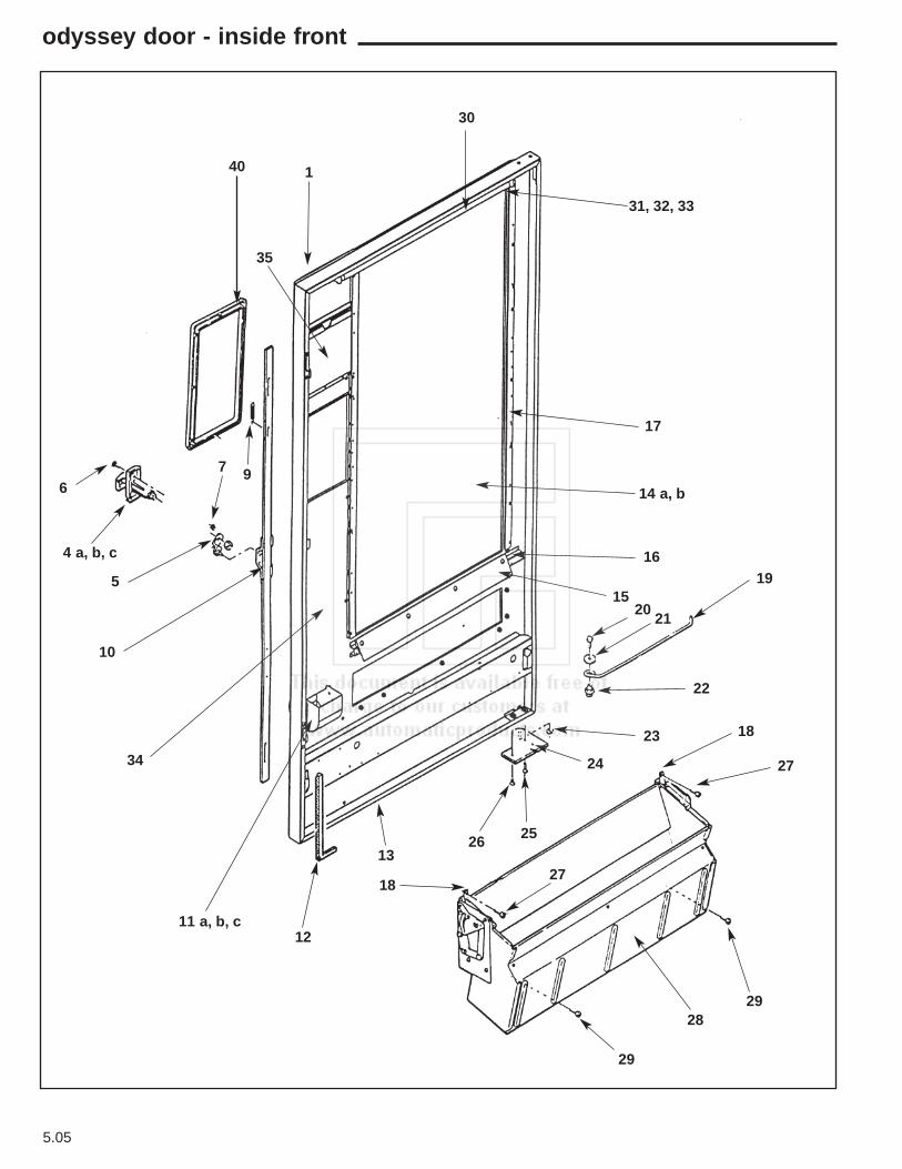
5.05
odyssey door - inside front
40 1
30
31, 32, 33
17
14 a, b
16
1519
2021
22
18
27
2928
29
2718
26 25
24
23
13
1211 a, b, c
34
10
5
7 9
4 a, b, c
6
35
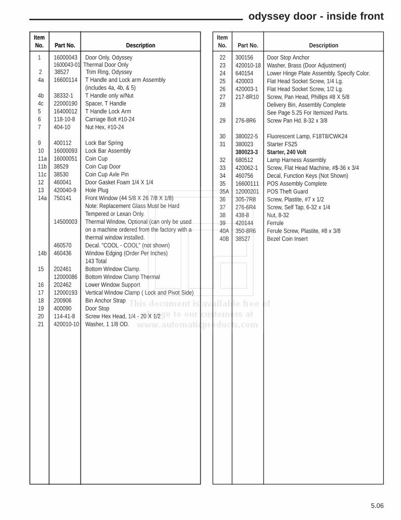
ItemNo. Part No. Description
ItemNo. Part No. Description
5.06
odyssey door - inside front
ItemNo. Part No. Description
1 16000043 Door Only, Odyssey 1600043-01 Thermal Door Only
2 38527 Trim Ring, Odyssey 4a 16600114 T Handle and Lock arm Assembly
(includes 4a, 4b, & 5) 4b 38332-1 T Handle only w/Nut 4c 22000190 Spacer, T Handle 5 16400012 T Handle Lock Arm 6 118-10-8 Carriage Bolt #10-24 7 404-10 Nut Hex, #10-24
9 400112 Lock Bar Spring 10 16000093 Lock Bar Assembly 11a 16000051 Coin Cup 11b 38529 Coin Cup Door 11c 38530 Coin Cup Axle Pin 12 460041 Door Gasket Foam 1/4 X 1/4 13 420040-9 Hole Plug 14a 750141 Front Window (44 5/8 X 26 7/8 X 1/8)
Note: Replacement Glass Must be Hard Tempered or Lexan Only.
14500003 Thermal Window, Optional (can only be used on a machine ordered from the factory with a thermal window installed.
460570 Decal. "COOL - COOL" (not shown)14b 460436 Window Edging (Order Per Inches)
143 Total 15 202461 Bottom Window Clamp.
12000086 Bottom Window Clamp Thermal16 202462 Lower Window Support 17 12000193 Vertical Window Clamp ( Lock and Pivot Side) 18 200906 Bin Anchor Strap 19 400090 Door Stop 20 114-41-8 Screw Hex Head, 1/4 - 20 X 1/221 420010-10 Washer, 1 1/8 OD.
22 300156 Door Stop Anchor 23 420010-18 Washer, Brass (Door Adjustment) 24 640154 Lower Hinge Plate Assembly. Specify Color.25 420003 Flat Head Socket Screw, 1/4 Lg.26 420003-1 Flat Head Socket Screw, 1/2 Lg.27 217-8R10 Screw, Pan Head, Phillips #8 X 5/828 Delivery Bin, Assembly Complete
See Page 5.25 For Itemized Parts.29 276-8R6 Screw Pan Hd. 8-32 x 3/8
30 380022-5 Fluorescent Lamp, F18T8/CWK2431 380023 Starter FS25
380023-3 Starter, 240 Volt32 680512 Lamp Harness Assembly33 420062-1 Screw, Flat Head Machine, #$-36 x 3/434 460756 Decal, Function Keys (Not Shown)35 16600111 POS Assembly Complete35A 12000201 POS Theft Guard36 305-7R8 Screw, Plastite, #7 x 1/237 276-6R4 Screw, Self Tap, 6-32 x 1/438 438-8 Nut, 8-3239 420144 Ferrule40A 350-8R6 Ferule Screw, Plastite, #8 x 3/840B 38527 Bezel Coin Insert
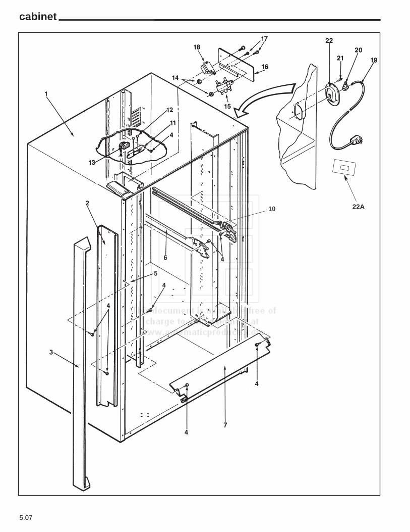
5.07
cabinet
22A10
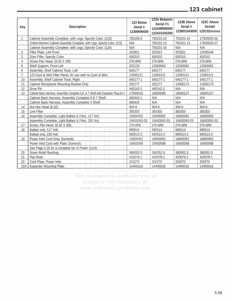
5.08
123 cabinet
Key Description
1 Cabinet Assembly Complete, with Legs. Specify Color. (123) 750100-5 750101-10 750101-10 17500025-02Chilled Machine Cabinet Assembly Complete, with Legs. Specify Color. (123) N/A 750101-13 750101-13 17500025-07Cabinet Assembly Complete, with Legs. Specify Color. (124) N/A 750101-16 N/A N/A
2 Filler Plate, Left Front. 202821 202821 202821 120002463 Door Filler, Specify Color. 600310 600310 600310 6003104 Screw Pan Head, (8-32 X 3/8) 276-8R6 276-8R6 276-8R6 276-8R65 Shelf Support, Front Left 202120 12000062 12000062 120000626 Assembly, Shelf Cabinet Track, Left 640177 640177 640177 6401777 123 Gum & Mint Filler Panel, for use with no Gum & Mint 12000121 12000121 12000121 1200012110 Assembly, Shelf Cabinet Track, Right. 640177-1 640177-1 640177-1 640177-111 Cabinet Receptacle Mounting Bracket Only 202177 202177 12000173 1200017312 Drive Pin 440142-2 440142-2 N/A N/A13 Cabinet Back Harness, Assembly Complete 5,6, & 7 Shelf with Expander Plug.Kit # 17500015 16600085 16600127 16600127
Cabinet Back Harness, Assembly Complete 6 & 7 Shelf. 660442-1 N/A N/A N/ACabinet Back Harness, Assembly Complete 5 Shelf. 660442 N/A N/A N/A
14 Nut Hex Head (6-32) 404-6 404-6 404-6 404-615 Line Filter 380303 380303 380303 38030316 Assembly Complete, Light Ballast & Filter, 117 Volt. 16600092 16600092 16600092 16600092
Assembly Complete, Light Ballast & Filter, 230 Volt. 16600092-03 16600092-03 16600092-03 16600092-0317 Screw, Pan Head, (6-32 X 3/8) 276-6R6 276-6R6 276-6R6 276-6R618 Ballast only, 117 Volt. 680514 680514 680514 680514
Ballast only, 230 Volt. 680513-2 680513-2 680513-2 680513-219 Power Inlet Cord Only, Domestic. 16800052 16800052 16800052 16800052
Power Inlet Cord with Plate, Domestic. 16600098 16600098 16600098 16600098See Page 5.16 for a complete list of Power Cords
20 Strain Relief Bushing. 380052-3 380052-3 380052-3 380052-321 Pop Rivet 420078-1 420078-1 420078-1 420078-122 Cord Plate, Power Inlet. 202270 202270 202070 20207022A Expander Mounting Plate. 14400016 14400016 14400016 14400016
123 BelowSerial #
12399090000
123A BetweenSerial #’s
123A99090000123A01042200
123B AboveSerial #
123B01043000
123C AboveSerial#
123C02xxxxxx
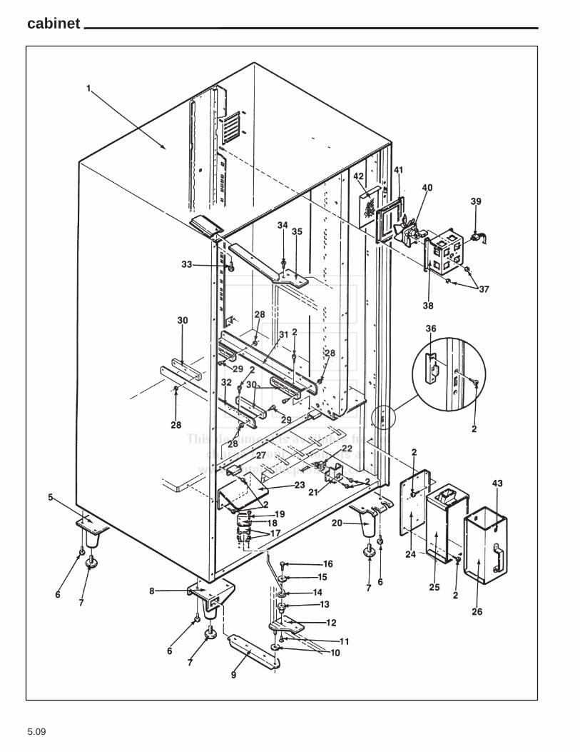
5.09
cabinet
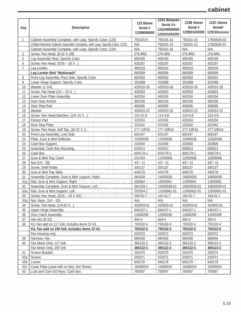
5.10
cabinet
Key Description
1 Cabinet Assembly Complete, with Legs. Specify Color. (123) 750100-5 750101-10 750101-10 17500025-02Chilled Machine Cabinet Assembly Complete, with Legs. Specify Color. (123) N/A 750101-13 750101-13 17500025-07Cabinet Assembly Complete, with Legs. Specify Color. (124) N/A 750101-16 N/A N/A
2 Screw, Pan Head, (8-32 X 3/8) 276-8R6 276-8R6 276-8R6 276-8R65 Leg Assembly Rear, Specify Color. 600195 600195 600195 6001956 Screw, Hex Head, (5/16 – 18 X _) 420187 420187 420187 4201877 Leg Leveler. 300103 300103 300103 300103
Leg Leveler Bolt "Multisnack". 660599 660599 660599 6605998 Front Leg Assembly, Pivot Side, Specify Color. 600302 600302 600302 6003029 Lower Hinge Support, Specify Color. 202088 202088 202088 20208810 Washer (1-1/4). 420010-18 420010-18 420010-18 420010-1811 Screw, Flat Head (1/4 – 20 X _) 420003 420003 420003 42000312 Lower Door Plate Assembly 640154 640154 640154 64015413 Door Stop Anchor 300156 300156 300156 30015614 Door Stop Rod 400095 400095 400095 40009515 Washer 420010-10 420010-10 420010-10 420010-1016 Screw, Hex Head Machine, (1/4–20 X _) 114-41-8 114-4-8 114-4-8 114-4-817 Friction Pad 420204 420204 420204 42020418 Door Stop Plate 201042 201042 201042 20104219 Screw, Pan Head, Self Tap, (10-32 X 1) 277-10R16 277-10R16 277-10R16 277-10R1620 Front Leg Assembly, Lock Side. 600197 600197 600197 60019723 Plate, Gum & Mint Deflector. 12000038 12000038 12000038 1200003824 Cash Box Support. 202809 202809 202809 20280925 Assembly, Cash Box Mounting. 600813 600813 600813 60081326 Cash Box. 600179-1 600179-1 600179-1 600179-127 Gum & Mint Tray Catch 201453 12000006 12000006 1200000628 Nut (1/4 - 28) 437- 41 437- 41 437- 41 437- 4129 Screw, Shelf Roller. 300137 300137 300137 30013730 Gum & Mint Tray Slide. 440278 440278 440278 44027831 Assembly Complete, Gum & Mint Support, Right. 660439 16600039 16600039 1660003931a Rail, Gum & Mint Support, Right. 202064 12000061 12000061 1200006132 Assembly Complete, Gum & Mint Support, Left. 660439-1 16600039-01 16600039-01 16600039-0132a Rail, Gum & Mint Support, Left. 202064-1 12000061-01 12000061-01 12000061-0133 Screw, Hex Head, (5/16 – 18 X 3/8). 164-51-7 164-51-7 164-51-7 164-51-733a Nut, Keps, (1/4 – 20). N/A N/A N/A N/A34 Screw, Flat Head, (1/4-20 X _). 420003-01 420003-01 420003-01 420003-0135 Upper Hinge Assembly. 640107-1 640107-1 640107-1 640107-136 Door Catch Assembly. 12000290 12000290 12000290 1200029037 Hex Nut (8-32). 404-4 404-4 404-4 404-438 Kit, Fan add on 117 Volt. Includes items 37-43. 750102-4 750102-4 750102-4 750102-4
Kit, Fan add on 240 Volt. Includes items 37-43. 750102-5 750102-5 750102-5 750102-5Fan Housing only. 202072 202072 202072 202072
39 Harness, Fan. 680456 680456 680456 68045640 Fan Motor Only, 117 Volt. 360122-2 360122-2 360122-2 360122-2
Fan Motor Only, 230 Volt. 360122-3 360122-3 360122-3 360122-341 Screen Bracket. 202070 202070 202070 20207042a Screen. 202071 202071 202071 20207142b Louver. 640178 640178 640178 64017842c Cover Plate (used with no fan), Not Shown. 16400024 16400024 16400024 1640002443 Lock and Cam w/2 Keys, Cash Box. 750097 750097 750097 750097
123 BelowSerial #
12399090000
123A BetweenSerial #’s
123A99090000123A01042200
123B AboveSerial #
123B01043000
123C AboveSerial#
123C02xxxxxx

5.11
120 / swing panel
23
6
20
22
17
18
19
2123 24
25
26
27
23
28
23
2329
30
33
32
31
9
8
10
4
3
5
7
15
14
13
12
2
11
1
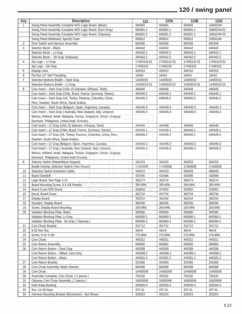
5.12
120 / swing panel
Key Description1 Swing Panel Assembly Complete W/O Logic Board. (Black) 660681 660681 660681 16600244
Swing Panel Assembly Complete W/O Logic Board. (Euro Gray) 660681-1 660681-1 660681-1 16600244-01Swing Panel Assembly Complete W/O Logic Board. (Odyssey) 660681-2 660681-2 660681-2 16600244-02Swing Panel Weldment, Specify Color. 600812 600812 600812 16000146
2 Door Switch and Harness Assembly. 660266 660266 660266 6602663 Selector Bezel – Black 440442 440442 440442 440442
Selector Bezel – Lt Gray 440442-1 440442-1 440442-1 440442-1Selector Bezel - Dk Gray. (Odyssey) 440442-2 440442-2 440442-2 440442-2
4 Api Logo – Lt Gray. 17400102-01 17400102-01 17400102-01 17400102-01Api Logo – Dk Gray. 17400102 17400102 17400102 17400102
5 Display Lens. 440310 440310 440310 4403106 Pal Nut 1/4" Self Threading. 18443 18443 18443 184437 Selection Buttons Braille – Dark Gray. 14400015 14400015 14400015 14400015
Selection Buttons Braille – Lt Gray. 14400015-01 14400015-01 14400015-01 14400015-018 Coin Insert – Dark Gray (USA, El Salvador, Ethiopia, Tahiti). 440445 440445 440445 440445
Coin Insert – Dark Gray (Chile, Brazil, France, Germany, Taiwan). 440445-1 440445-1 440445-1 440445-1Coin Insert – Dark Gray (UK, Turkey, Panama, Columbia, China, 440445-2 440445-2 440445-2 440445-2Peru, Sweden, South Africa, Saudi Arabia).Coin Insert – Dark Gray (Belgium, Spain, Argentina, Canada). 440445-3 440445-3 440445-3 440445-3Coin Insert – Dark Gray ( Australia, New Zealand, Italy, Lebanon, 440445-4 440445-4 440445-4 440445-4Mexico, Holland, Israel, Malaysia, Tunisia, Singapore, Oman, Uruguay, Denmark, Philippines, United Arab Emirate).Coin Insert – LT Gray (USA, El Salvador, Ethiopia, Tahiti). 440445 440445 440445 440445Coin Insert – LT Gray (Chile, Brazil, France, Germany, Taiwan). 440445-1 440445-1 440445-1 440445-1Coin Insert – LT Gray (UK, Turkey, Panama, Columbia, China, Peru, 440445-2 440445-2 440445-2 440445-2Sweden, South Africa, Saudi Arabia).Coin Insert – LT Gray (Belgium, Spain, Argentina, Canada). 440445-3 440445-3 440445-3 440445-3Coin Insert – LT Gray ( Australia, New Zealand, Italy, Lebanon, 440445-4 440445-4 440445-4 440445-4Mexico, Holland, Israel, Malaysia, Tunisia, Singapore, Oman, Uruguay, Denmark, Philippines, United Arab Emirate).
9 Selector Switch (MasterMenu Keypad). 360253 360253 360253 360253Braille Overlay, Selection Switch ( Not Shown) 17400008 17400008 17400008 17400008
10 Selection Switch Extension Cable. 680633 680633 680633 68063311 Board Standoff. 420096 420096 420096 42009612 Logic Board, See Page 5.15 360274 360274 360274 36027413 Board Mounting Screw, 8 X 3/8 Plastite. 305-8R6 305-8R6 305-8R6 305-8R614 Board Cover W/O Decal. 202802 202802 202802 20280215 Decal, Board Cover. 460734 460734 460734 46073417 Display Board. 360244 360244 360244 36024418 Insulator, Display Board. 360256 360256 360256 36025619 Screw, Display Board Mounting. 200-6R6 200-6R6 200-6R6 200-6R620 Validator Blocking Plate, Black. 660580 660580 660580 660580
Validator Blocking Plate, Lt Gray. 660580-1 660580-1 660580-1 660580-1Validator Blocking Plate, Dk Gray. ( Odyssey ) 660580-2 660580-2 660580-2 660580-2
21 Coin Chute Bracket. 201712 201712 201712 20171222 8-32 Hex Nut. 404-8 404-8 404-8 404-823 Screw, 8-32 X 3/8 276-8R6 276-8R6 276-8R6 276-8R624 Coin Chute. 440311 440311 440311 44031125 Coin Return Assembly. 660682 660682 660682 66068226 Coin Return Button – Dark Gray 440289 440289 440289 440289
Coin Return Button – Milled, Card Only. 440289-1 440289-1 440289-1 440289-1Coin Return Button – Black. 440281-2 440281-2 440281-2 440281-2
27 Coin Return Bracket. 201660 201660 201660 20166028 Coin Chute Assembly, Water Diverter. 660488 660488 660488 66048829 Coin Chute. 14400008 14400008 14400008 1440000830 Assembly Complete, Coin Chute. ( 2 pieces ) 750182 750182 750182 75018231 Odyssey Coin Chute Assembly. ( 2 pieces ) 16600069 16600069 16600069 1660006932 Hole Snap Bushing. 420040-3 420040-3 420040-3 420040-333 Nut, 1/4-28 Keps. 437-41 437-41 437-41 437-4134 Harness Mounting Bracket (Micromech) . Not Shown. 202024 202024 202024 202024
123 123A 123B 123C
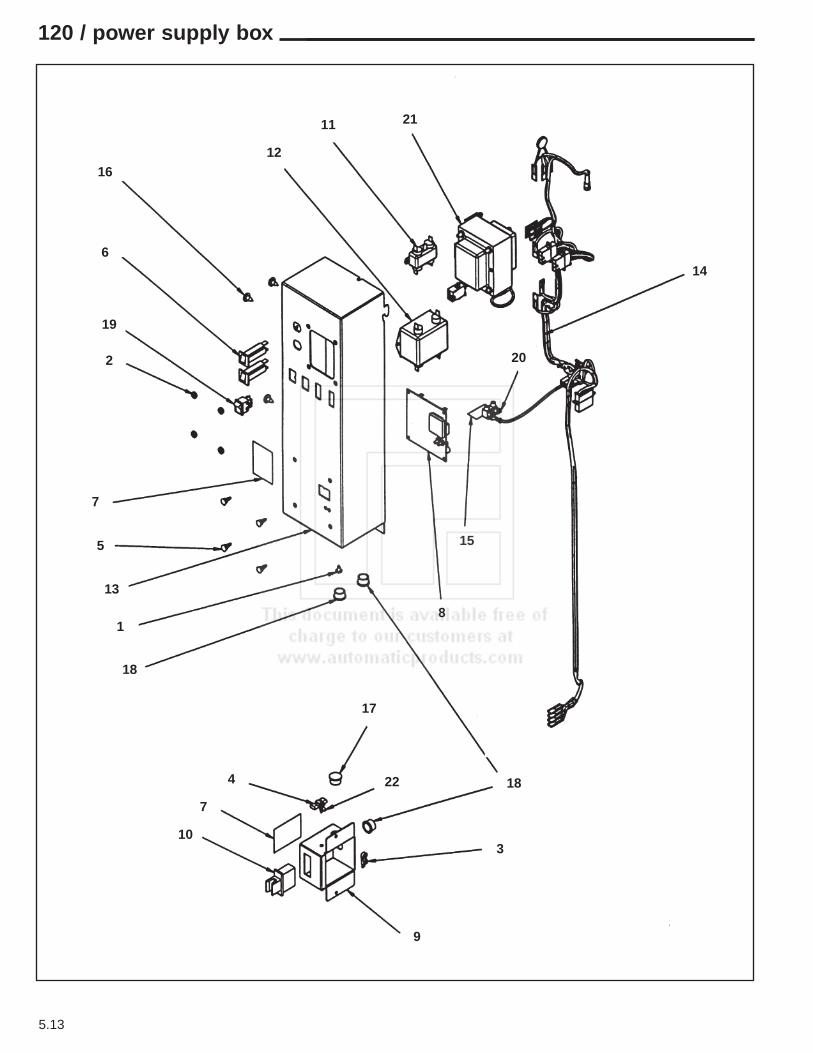
5.13
120 / power supply box
14
20
15
8
18
3
9
10
7
4
17
22
18
1
13
5
7
2
19
6
1612
11 21

ItemNo. Part No. Description
ItemNo. Part No. Description
16600073 Junction Box Complete 117V Ambient, Domestic. (When using in machines sel # 12399094999 or below alsoorder part # 12000103).
16600053 Junction Box Complete 117V, Chilled, Domestic16600053-01 Dual Zone Junction Box Complete 117V.
16600057 Junction Box Complete 117V Chilled Export16600074 Junction Box Complete 117V Ambient, Export.16600075 Junction Box Complete 230V Ambient, Export.16600054 Junction Box Complete 230V, Chilled, Export
16600054-01 Dual Zone Junction Box Complete 230V210-8R6 # 8 X 3/8 Screw
2 438-8 8-32 Nut3 380078 Cable Tie4 380263 Interlock Cheat Tool5 17100002 Circuit Board Standoff6 380241 Circuit Breaker 3 Amp7 460642 Decal, Voltage 8 13600001 Chilled Digital Temp Control Assembly, Includes
Board and Probe.13600005 Dual Zone Temp Control Assembly, Includes
Board and Probe’s.13600001-01 Chilled Temp Control, Board Only.13600005-01 Dual Zone Temp Control, Board Only.13600001-02 Probe Only, Dual Zone (2 each) & Chilled
(1 each).9 12000122 Door Switch Box10 380262 Door Switch11 380303 RFI Filter12 380304 RFI Filter13 12000099 Weldment, Junction Box14 16800031 Junction Box Harness, 117V, Ambient
16800022 Junction Box Harness 117V, Chilled & Dual Zone16800015 Junction Box Harness 230V, Chilled & Dual
Zone 16800030 Junction Box Harness, 230V, Ambient, Export.
16800030-01 Junction Box Harness, 117V, Ambient, Export.15 440065 Mylar Insulation16 216-41R8 Screw 1/4 X 217 420040-1 Snap Bushing / Hole Plug18 420040-2 Snap Bushing / Hole Plug19 380243 Rocker Switch20 380285 Terminal Block21 13900003 Transformer, 117V
13900004 Transformer, 230V22 380321 Clip for Interlock Switch Tool23 12000103 Power Box Mounting Panel (not shown).
5.14
120 / power supply box

5.15
logic board
15 4
3 2
14
13
12
11
109
8
7
6
15

ItemNo. Part No. Description
ItemNo. Part No. Description
120 / logic board harnesses and components
Description DescriptionDescription
5.16
1 360274 Logic Board2 360272 Microprocessor3 360266 Flash Memory Chip4 380308 Battery, 3.6 V Lithium W/Harness5 680629 Display Harness6 680633 Ribbon Cable, Master Menu Extension
Harness.7 680319 Executive Coin Mech Harness.8 680637 Harness, Pulse Bill Validator.
680355-1 Harness Pulse Bill Validator Door Mount9 680630 Harness, Power Box to Board.10 16600085 Cabinet Back Harness 5, 6 &7. Shelf with
Expander Capability*660442 Cabinet Back Harness, 5 shelf*660442-1 Cabinet Back Harness, 6 shelf*660442-2 Cabinet Back Harness, 7 shelf
11 680547 Harness, Micromech Coin Changer.12 680632 Harness, Operate/Service Interlock Switch.13 680509 Printer Harness/Dex Harness, Loose
16800044 Dex Harness Panel Mount14 16800013 Touch Memory Harness15 680642 MDB Extension
16800017 MDB Extension, Door Mount Validator680659-1 Com/Power Harness, Digital Control
Description
Part No. Description
16600098 Line Cord, 120V, Domestic.16600099 Line Cord, 230V, Europe.
16600099-01 Line Cord, 230V, Australia.16600099-02 Line Cord, 230V, Isreal.16600099-03 Line Cord, 230V, APi / UK.16600099-04 Line Cord, 230V, SAF16600099-05 Line Cord, 230V, UK.16600099-06 Line Cord, 230V, Multisnack.
680456-1 Light Harness & Fan Harness680512 Lamp Harness Assembly680547 Micromech changer harness680319 Executive changer harness680637 Pulse bill validator harness
Part No. Description
cabinet harnesses
OPTIONS17500005 MasterMenu Online Package, Complete17500004 PC to Chip Harness16800013 Harness Board to Chip17500003 Chip with Holder56800022 Harness PC to Logic Board13700005 Doubletalk (Voice Synthesizer)16800042 Harness, Doubletalk
Part #'s marked with an (*) are for machines serial # 12399090000 and below.
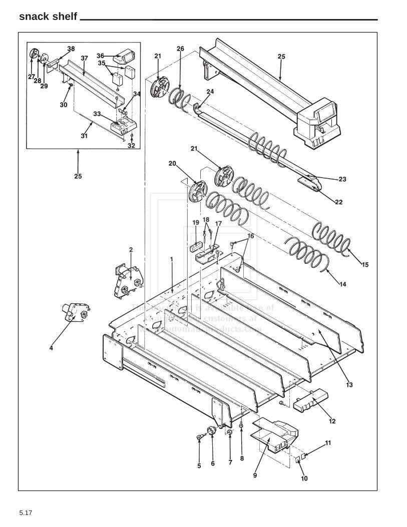
5.17
snack shelf

5.18
snack shelf
Key Description
1 Snack Shelf w/o Spirals, Complete, including motors and harness 750121-10 750121-15Dual Snack Shelf w/o Spirals, Complete, including motors and harness 750162-9 750162-13Snack Shelf Only (Weldment) 600761 600761
2 Dual Spiral Motor Only, White/Blue 360240 360240Kit, Dual Spiral Add on 750159-2 750159-2
4 Vend Motor Complete, White/Blue 360275 3602755 Screw, Shelf Roller 300203 3002036 Roller, Shelf 440362 4403627 Nut, Keps (1/4 x 28) 437-41 437-418 Screw, Pan Head, Phillips, Plastite (8-16 x 3/8) 305-8R6 305-8R69 Price and Selection Tab Holder (Single Spiral) 440285 44028510 Item Tabs 460669 46066911 Price Tabs. See Chart on Page 5.2212 Dual Spiral Pastry Shelf Front 440367 44036713 Spacer, Snack Shelf 640101 640101
Snack Shelf Extender (Not Shown) 202770 20277014 Left Hand Dual Spirals, See Chart at bottom of page15 Right Hand Dual Spirals, See Chart at bottom of page16 Screw, Pan Head. Self Tap (8-32 x 3/8) 276-8R6 276-8R617 Bracket Only 600601 1600008318 Pin, Shelf Plug 420142-2 420046-419 Assembly Complete, Harness Plug and Bracket 660435-2 660435-7
Harness only, no Bracket 680448 1680004920 Sprial Retainer, Left Hand. Gray 440406 44040621 Spiral Retainer, Right Hand. White 440405 44040522 Front Rail Support Only 201534 20153423 Product Rail Assembly, for use with Single Pastry Spiral 660330-2 660330-224 Rear Bracket Only 200913 20091325 Kit, Can Dispenser 750083 75008326 Single Snack Spirals, See Chart at bottom of page27 Drive Cam Rear 440201 44020128 Retaining Ring #31 751-31 751-3129 Drive Cam, Front 440200 44020030 Shoulder Bushing 300184 300184
Screw Type # 23 277-10R8 277-10R831 Actuator Wire 400094-1 40009432 Screw, Plastite (8-16 x 3/8) 305-8R6 305-8R633 Price & Selection Trim 440196 44019634 Stop Leveler 440199 44019935 Leg, Top Can Guide & Sign Trim 440198 44019836 Top Can Guide & Sign Trim 440197 44019737 Can Dispenser, Trough Only 600308-1 60030838 Cam, Mounting Bracket & Spring Assembly 640109 640109
123 & 123A 123B & 123C
Single Snack Spirals Left Hand Dual Spirals Right Hand Dual Spirals121 122-123 121 122-123 121 122-123
3 Space N/A N/A 400184-1 N/A 400185-1 N/A4 Space 400165-1 14000002-01 400186-1 N/A 400183-1 N/A6 Space 400124-1 400162-1 400174-1 14000003-01 400173-1 400167-17 Space N/A 400153-1 N/A 400178-1 N/A 400164-18 Space 400125-1 N/A 400175-1 N/A 400116-1 N/A9 Space N/A N/A N/A 400179-1 N/A 400166-110 Space 400126-1 400127-1 400176-1 400169-1 400117-1 400168-112 Space N/A 400128-1 N/A 400170-1 N/A 400120-115 Space N/A 400129-1 N/A 400171-1 N/A 400121-130 Space N/A 400136-1 N/A N/A N/A N/A40 Space N/A 400137-1 N/A N/A N/A N/A
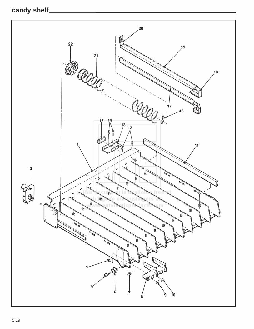
5.19
candy shelf
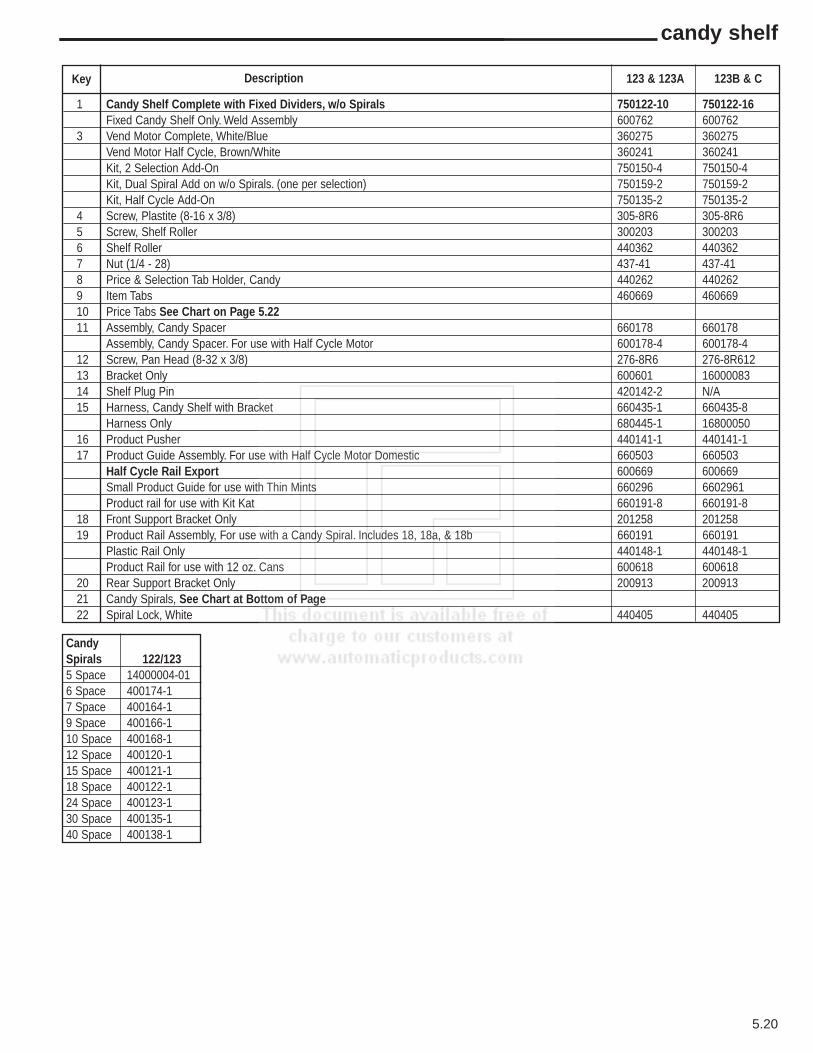
5.20
candy shelf
Key Description
1 Candy Shelf Complete with Fixed Dividers, w/o Spirals 750122-10 750122-16Fixed Candy Shelf Only. Weld Assembly 600762 600762
3 Vend Motor Complete, White/Blue 360275 360275Vend Motor Half Cycle, Brown/White 360241 360241Kit, 2 Selection Add-On 750150-4 750150-4Kit, Dual Spiral Add on w/o Spirals. (one per selection) 750159-2 750159-2Kit, Half Cycle Add-On 750135-2 750135-2
4 Screw, Plastite (8-16 x 3/8) 305-8R6 305-8R65 Screw, Shelf Roller 300203 3002036 Shelf Roller 440362 4403627 Nut (1/4 - 28) 437-41 437-418 Price & Selection Tab Holder, Candy 440262 4402629 Item Tabs 460669 46066910 Price Tabs See Chart on Page 5.2211 Assembly, Candy Spacer 660178 660178
Assembly, Candy Spacer. For use with Half Cycle Motor 600178-4 600178-412 Screw, Pan Head (8-32 x 3/8) 276-8R6 276-8R61213 Bracket Only 600601 1600008314 Shelf Plug Pin 420142-2 N/A15 Harness, Candy Shelf with Bracket 660435-1 660435-8
Harness Only 680445-1 1680005016 Product Pusher 440141-1 440141-117 Product Guide Assembly. For use with Half Cycle Motor Domestic 660503 660503
Half Cycle Rail Export 600669 600669Small Product Guide for use with Thin Mints 660296 6602961Product rail for use with Kit Kat 660191-8 660191-8
18 Front Support Bracket Only 201258 20125819 Product Rail Assembly, For use with a Candy Spiral. Includes 18, 18a, & 18b 660191 660191
Plastic Rail Only 440148-1 440148-1Product Rail for use with 12 oz. Cans 600618 600618
20 Rear Support Bracket Only 200913 20091321 Candy Spirals, See Chart at Bottom of Page22 Spiral Lock, White 440405 440405
123 & 123A 123B & C
CandySpirals 122/1235 Space 14000004-016 Space 400174-17 Space 400164-19 Space 400166-110 Space 400168-112 Space 400120-115 Space 400121-118 Space 400122-124 Space 400123-130 Space 400135-140 Space 400138-1
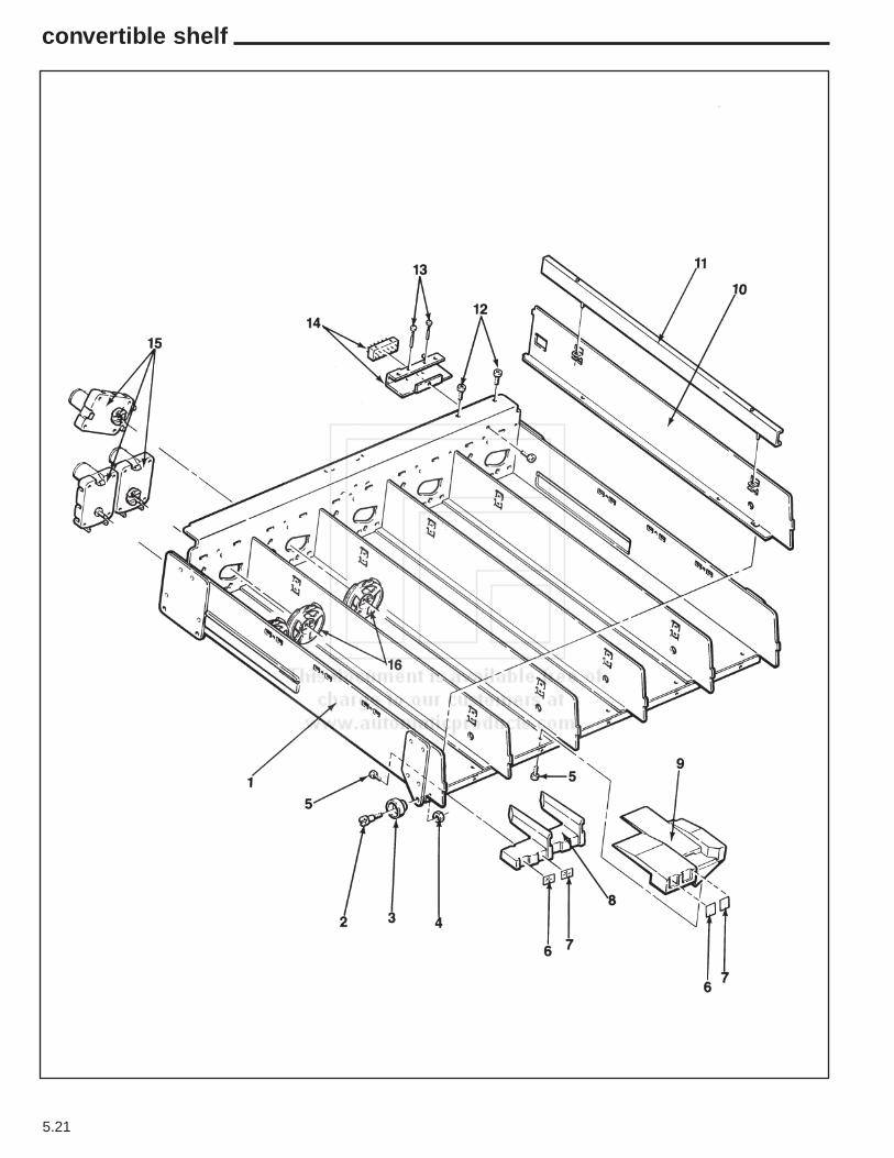
5.21
convertible shelf
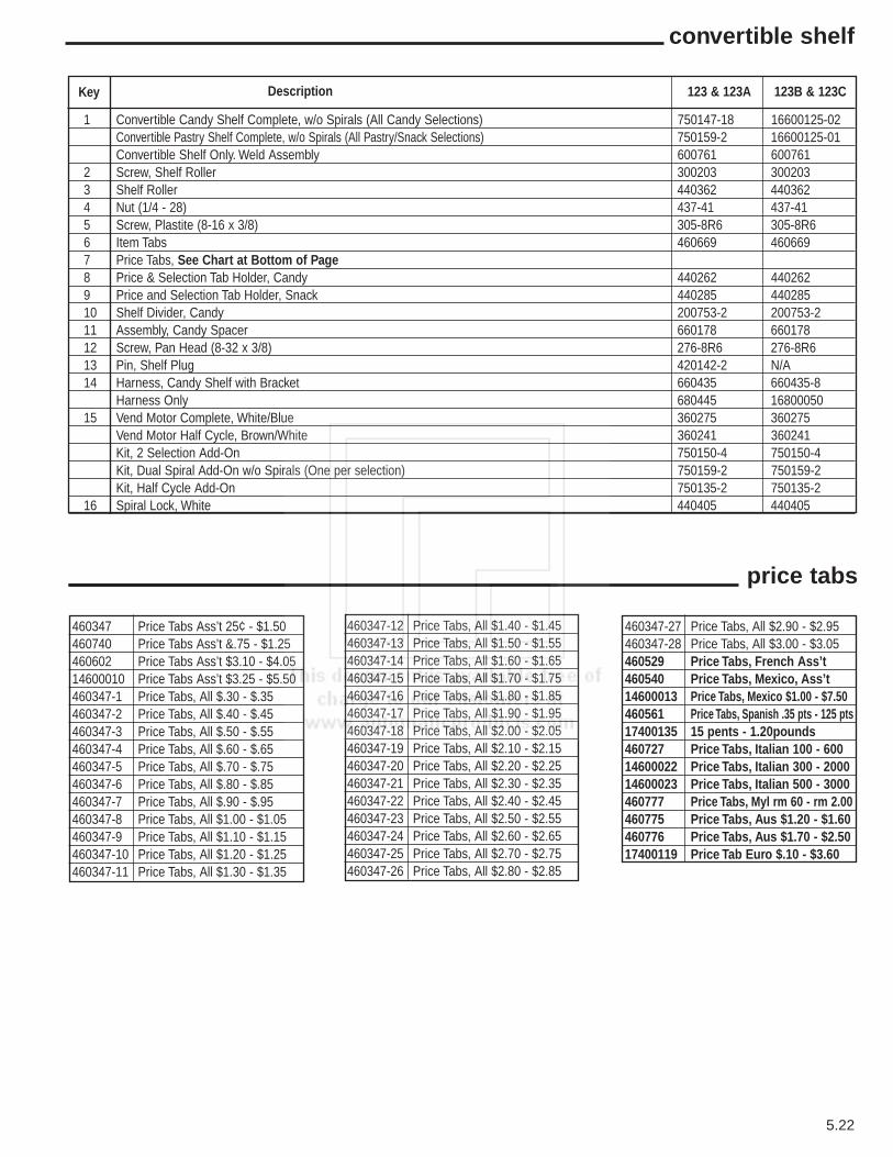
5.22
convertible shelf
Key Description
1 Convertible Candy Shelf Complete, w/o Spirals (All Candy Selections) 750147-18 16600125-02Convertible Pastry Shelf Complete, w/o Spirals (All Pastry/Snack Selections) 750159-2 16600125-01Convertible Shelf Only. Weld Assembly 600761 600761
2 Screw, Shelf Roller 300203 3002033 Shelf Roller 440362 4403624 Nut (1/4 - 28) 437-41 437-415 Screw, Plastite (8-16 x 3/8) 305-8R6 305-8R66 Item Tabs 460669 4606697 Price Tabs, See Chart at Bottom of Page8 Price & Selection Tab Holder, Candy 440262 4402629 Price and Selection Tab Holder, Snack 440285 44028510 Shelf Divider, Candy 200753-2 200753-211 Assembly, Candy Spacer 660178 66017812 Screw, Pan Head (8-32 x 3/8) 276-8R6 276-8R613 Pin, Shelf Plug 420142-2 N/A14 Harness, Candy Shelf with Bracket 660435 660435-8
Harness Only 680445 1680005015 Vend Motor Complete, White/Blue 360275 360275
Vend Motor Half Cycle, Brown/White 360241 360241Kit, 2 Selection Add-On 750150-4 750150-4Kit, Dual Spiral Add-On w/o Spirals (One per selection) 750159-2 750159-2Kit, Half Cycle Add-On 750135-2 750135-2
16 Spiral Lock, White 440405 440405
123 & 123A 123B & 123C
price tabs
460347 Price Tabs Ass’t 25¢ - $1.50460740 Price Tabs Ass’t &.75 - $1.25460602 Price Tabs Ass’t $3.10 - $4.0514600010 Price Tabs Ass’t $3.25 - $5.50460347-1 Price Tabs, All $.30 - $.35460347-2 Price Tabs, All $.40 - $.45460347-3 Price Tabs, All $.50 - $.55460347-4 Price Tabs, All $.60 - $.65460347-5 Price Tabs, All $.70 - $.75460347-6 Price Tabs, All $.80 - $.85460347-7 Price Tabs, All $.90 - $.95460347-8 Price Tabs, All $1.00 - $1.05460347-9 Price Tabs, All $1.10 - $1.15460347-10 Price Tabs, All $1.20 - $1.25460347-11 Price Tabs, All $1.30 - $1.35
460347-12 Price Tabs, All $1.40 - $1.45460347-13 Price Tabs, All $1.50 - $1.55460347-14 Price Tabs, All $1.60 - $1.65460347-15 Price Tabs, All $1.70 - $1.75460347-16 Price Tabs, All $1.80 - $1.85460347-17 Price Tabs, All $1.90 - $1.95460347-18 Price Tabs, All $2.00 - $2.05460347-19 Price Tabs, All $2.10 - $2.15460347-20 Price Tabs, All $2.20 - $2.25460347-21 Price Tabs, All $2.30 - $2.35460347-22 Price Tabs, All $2.40 - $2.45460347-23 Price Tabs, All $2.50 - $2.55460347-24 Price Tabs, All $2.60 - $2.65460347-25 Price Tabs, All $2.70 - $2.75460347-26 Price Tabs, All $2.80 - $2.85
460347-27 Price Tabs, All $2.90 - $2.95460347-28 Price Tabs, All $3.00 - $3.05460529 Price Tabs, French Ass’t460540 Price Tabs, Mexico, Ass’t14600013 Price Tabs, Mexico $1.00 - $7.50460561 Price Tabs, Spanish .35 pts - 125 pts17400135 15 pents - 1.20pounds460727 Price Tabs, Italian 100 - 60014600022 Price Tabs, Italian 300 - 200014600023 Price Tabs, Italian 500 - 3000460777 Price Tabs, Myl rm 60 - rm 2.00460775 Price Tabs, Aus $1.20 - $1.60460776 Price Tabs, Aus $1.70 - $2.5017400119 Price Tab Euro $.10 - $3.60

5.23
gum & mint shelf
19

5.24
gum & mint shelf
Key Description
1 Assembly Complete, G & M Domestic 660316 16600019 16600198Add on Kit, G & M Domestic 750165 750165-18 750165-36Shelf Only, G & M Domestic 600420 16000004 16000004Assembly Complete, G & M Export 660317-6 16600018 16600200Add on Kit, G & M Export 501592 750165-16 750165-38Shelf Only, G & M Export 600463-3 16000007 16000007Assembly Complete, G & M Australia 660317-12 16600017 16600199Add on Kit, G & M Australia 750165-10 750165-17 750165-37Shelf Only, G & M Australia 600463-3 16000007 16000007
2 Snap Bushing 420040-9 420040-9 420040-93 Thin Mint Adapter 201412 201412 2014124 G & M Rear Pusher Stop, Domestic 201458-1 201458-1 201458-1
G & M Rear Pusher Stop, Export 201458-3 201458-3 201458-35 Screw (8-32 x 3/8), Pan Head, Self Tap 276-8R6 276-8R6 276-8R66 Screw (1 3/8), Pan Head, Phillips 217-8R22 217-8R22 217-8R227 Shoulder Bushing 300184 300184 3001848 G & M Shelf Latch, Left Side 12000032-01 12000032-01 12000032-019 G & M Motor, White 360105 360105 36010510 Screw (6-32 x 1/2) Flat Head 400089 Not Used Not Used11 G & M Mounting Bracket 600427 Not Used Not Used12 G & M Ejector 440267 440267 44026713 G & M Front Shelf Base 440266 440266 44026614 Screw (#8 x 1”) Pan Head 218-8R16 218-8R16 218-8R1615 Decal, G & M Shelf Latch 460352 460352 46035216 Display Stop, Column Front 440270 440270 44027017 G & M Shelf Front 440273 440273 44027318 Screw (#8 x 1 3/8) Pan Head 218-8R22 218-8R22 218-8R2219 Harness with Bracket, Domestic 660341 16600064 16600179
Harness W Bracket, Export & Australia 660341 16600067 16600182Harness only, no Bracket, Domestic 680306 16800002 16800077Harness only, no Bracket, Export & Aus 680328 16800005 16800080
20 Strap, G & M Pusher Stop, Domestic 201414-1 12000002-02 12000002-02Strap, G & M Pusher Stop, Export & Aus 201553 12000002 12000002
21 Screw (6-32 x 5/16) Flat Head 262-6R5 262-6R5 262-6R522 Spring, G & M Pusher Return 400106 400106 40010623 G & M Display Hinge Assy. Domestic & Export except Australia 660314 660314 660314
G & M Display Hinge Assy, Australia Only 660314-1 660314-1 660314-124 G & M Shelf Latch, Right Side 12000032 12000032 1200003225 Wing Nut (8 x 32) 420023 420023 42002326 Column Spacer, Left 201411-1 201411-1 201411-127 Column Spacer, Right 201411 201411 20141128 Shelf Grommet (NGS #122) 420296 420296 42029629 Caution Decal, G & M Shelf 460351 460351 46035130 Cover, G & M Shelf, Domestic 201409-2 201409-2 201409-2
Cover, G & M Shelf, Export & Aus 201530-2 201530-2 201530-231 Assembly Complete, Pusher & Spring 660313 660313 66031332 Roll Pin 801C125-12 801C125-12 801C125-1233 Pusher Only 440265 440265 44026534 Roller, G & M Pusher 440274 440274 44027435 Shelf Closer 201691 201691 201691
123 BelowSerial #
12399090000
123A BetweenSerial #’s
123A99090000123A01xxxxxx
123B & 123CAbove Serial #123B99090000
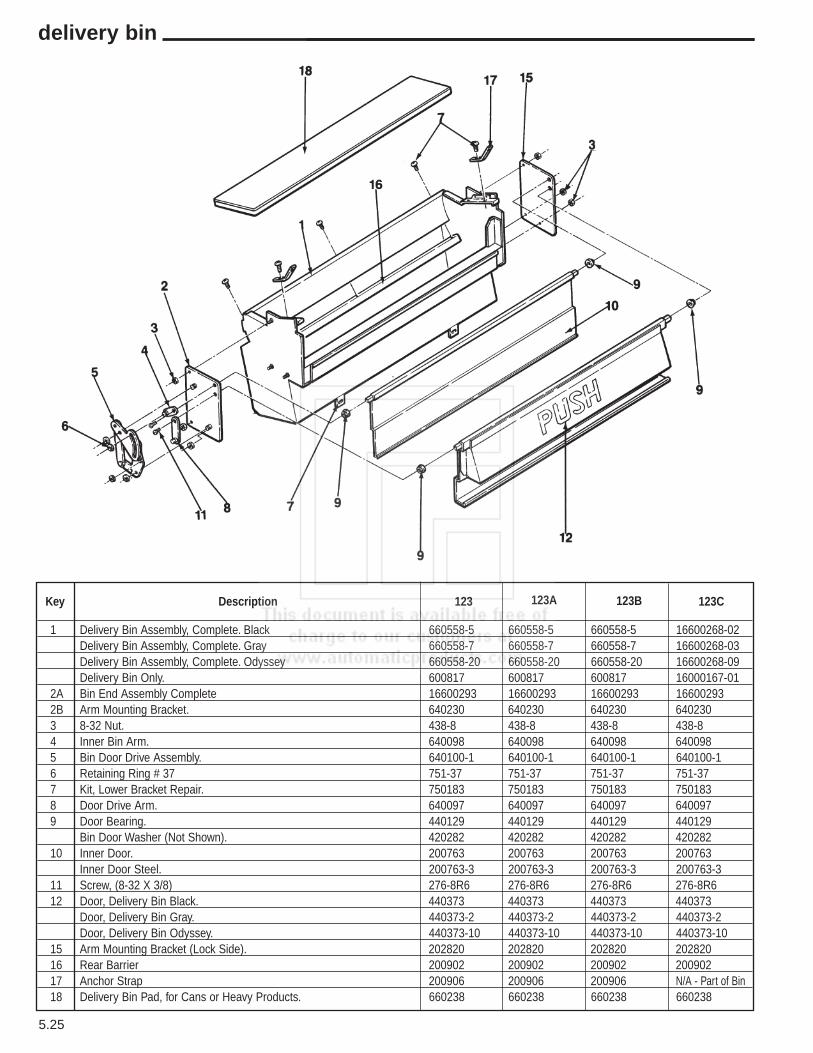
5.25
delivery bin
Key Description
1 Delivery Bin Assembly, Complete. Black 660558-5 660558-5 660558-5 16600268-02Delivery Bin Assembly, Complete. Gray 660558-7 660558-7 660558-7 16600268-03Delivery Bin Assembly, Complete. Odyssey 660558-20 660558-20 660558-20 16600268-09Delivery Bin Only. 600817 600817 600817 16000167-01
2A Bin End Assembly Complete 16600293 16600293 16600293 166002932B Arm Mounting Bracket. 640230 640230 640230 6402303 8-32 Nut. 438-8 438-8 438-8 438-84 Inner Bin Arm. 640098 640098 640098 6400985 Bin Door Drive Assembly. 640100-1 640100-1 640100-1 640100-16 Retaining Ring # 37 751-37 751-37 751-37 751-377 Kit, Lower Bracket Repair. 750183 750183 750183 7501838 Door Drive Arm. 640097 640097 640097 6400979 Door Bearing. 440129 440129 440129 440129
Bin Door Washer (Not Shown). 420282 420282 420282 42028210 Inner Door. 200763 200763 200763 200763
Inner Door Steel. 200763-3 200763-3 200763-3 200763-311 Screw, (8-32 X 3/8) 276-8R6 276-8R6 276-8R6 276-8R612 Door, Delivery Bin Black. 440373 440373 440373 440373
Door, Delivery Bin Gray. 440373-2 440373-2 440373-2 440373-2Door, Delivery Bin Odyssey. 440373-10 440373-10 440373-10 440373-10
15 Arm Mounting Bracket (Lock Side). 202820 202820 202820 20282016 Rear Barrier 200902 200902 200902 20090217 Anchor Strap 200906 200906 200906 N/A - Part of Bin18 Delivery Bin Pad, for Cans or Heavy Products. 660238 660238 660238 660238
123 123A 123B 123C
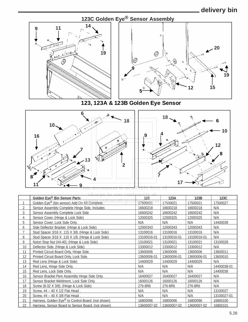
5.26
delivery bin
Golden Eye® Bin Sensor Parts 123 123A 123B 123C 1 Golden Eye® (bin sensor) Add On Kit Complete. 17500021 17500021 17500021 175000272 Sensor Assembly Complete Hinge Side, Includes 16600218 16600218 16600218 N/A3 Sensor Assembly Complete Lock Side 16600242 16600242 16600242 N/A4 Sensor Cover. (Hinge & Lock Side) 12000325 12000325 12000325 N/A5 Sensor Cover, Lock Side Only. N/A N/A N/A 144000396 Side Deflector Bracket. (Hinge & Lock Side) 12000343 12000343 12000343 N/A7 Stud Spacer 3/16 X .115 X 3/8. (Hinge & Lock Side) 13100016 13100016 13100016 N/A8 Stud Spacer 3/16 X .115 X 1/8. (Hinge & Lock Side) 13100016-01 13100016-01 13100016-01 N/A9 Nylon Stop Nut (#4-40). (Hinge & Lock Side) 13100021 13100021 13100021 1310002810 Deflector Side. (Hinge & Lock Side) 13300012 13300012 13300012 N/A11 Printed Circuit Board Only, Hinge Side. 13600006 13600006 13600006 1360001112 Printed Circuit Board Only, Lock Side. 13600006-01 13600006-01 13600006-01 1360001013 Red Lens (Hinge & Lock Side) 14400029 14400029 14400029 N/A14 Red Lens, Hinge Side Only. N/A N/A N/A 14400038-0115 Red Lens, Lock Side Only. N/A N/A N/A 1440003816 Sensor Bracket Pem Assembly Hinge Side Only. 16400027 16400027 16400027 N/A17 Sensor Bracket Weldment, Lock Side Only. 16000126 16000126 16000126 N/A18 Screw (8-32 X 3/8). (Hinge & Lock Side) 276-8R6 276-8R6 276-8R6 N/A19 Screw, #4 – 40 X 1/2 Flat Head . N/A N/A N/A 1310002720 Screw, #4 – 40 X 3/8 Flat Head . N/A N/A N/A 13100027-0121 Harness, Golden Eye® to Control Board. (not shown) 16800096 16800096 16800096 1680010022 Harness, Sensor Board to Sensor Board. (not shown) 13600007-02 13600007-02 13600007-02 16800101
9 1 1
1
5
2
91
11
16
1
1
8
61
9
7
4
2
9
8 4
7
1
1
1 1
1
123, 123A & 123B Golden Eye Sensor
9 11
16
1818
12 15
20
19
10
12
1711
10
6
13
19
14123C Golden Eye® Sensor Assembly

5.27
chill machine supplement
5
13
10
15
1412
12 3
4
2
2
9
6
8

5.28
chill machine supplement
Key Description
1 Chilled Cabinet Assembly Complete, with Legs. Specify Color. N/A 750101-13 750101-13 17500025-072 Screw, Pan Head, (8-32 X 3/8) N/A 276-8R6 276-8R6 276-8R64 Air Duct N/A 12000087 12000087 120000875 Door Gasket, Order by Inches. N/A 460468 460468 4604686 Front Vent Screen N/A 12000401 12000401 120004018 Door Gasket, Order by Inches. N/A 460468 460468 4604689 Right Retainer N/A 202145 202145 20214510 Left Retainer N/A 202144 202144 20214411 Refrigeration Assembly Complete 117 V, See Page 5.28 for Itemized Parts. N/A 16600041 16600041 16600041
Refrigeration Assembly Complete 230 V, See Page 5.28 for Itemized Parts. N/A 16600041-01 16600041-01 16600041-0112 Back Vent Screen Assembly. N/A 16600047 16600047 1660004713 Power Inlet Cord Only, Domestic. 16800052 16800052 16800052 16800052
Power Inlet Cord with Plate, Domestic. 16600098 16600098 16600098 16600098Power Inlet Cord with Plate, Europe. 16600099 16600099 16600099 16600099Power Inlet Cord with Plate, Australia. 16600099-01 16600099-01 16600099-01 16600099-01Power Inlet Cord with Plate, Israel 16600099-02 16600099-02 16600099-02 16600099-02Power Inlet Cord with Plate, UK. 16600099-03 16600099-03 16600099-03 16600099-03Power Inlet Cord with Plate, India. 16600099-04 16600099-04 16600099-04 16600099-04Power Inlet Cord with Plate, 120 Volt Export. 16600099-05 16600099-05 16600099-05 16600099-05
14 Screw, Pan Head, (#8-32 X 1/2). N/A 276-8R8 276-8R8 276-8R815 Air Deflector N/A 202842 202842 202842
Bin Close off Plate (not shown). N/A 12000003 12000003 12000003
Insulation - Chilled MachineRight Rear. N/A 12200001 12200001 12200001Right Shelf Support. N/A 12200002 12200002 12200002Back Left. N/A 12200004 12200004 12200004Shelf Rear. N/A 12200008 12200008 12200008Back. N/A 12200009 12200009 12200009Pivot Side. N/A 12200010 12200010 12200010Left Shelf Support. N/A 12200012 12200012 12200012Foam Insulation, Shelf. N/A 12200017 12200017 12200017Foam Insulation, Front. N/A 12200024 12200024 12200024Foam Insulation, Rear. N/A 12200025 12200025 12200025Shelf Front. N/A 12200030 12200030 12200030Foam Insulation, Rear Shelf Front, Pivot Side. N/A 12200032 12200032 12200032Top. N/A 12200034 12200034 12200034Lock Side. N/A 12200035 12200035 12200035Top Lock Side Insulation, Shelf. N/A 12200036 12200036 12200036Insulation Back. N/A 12200037 12200037 12200037Insulation Cabinet top. N/A 12200038 12200038 12200038Insulation, Top Front. N/A 12200039 12200039 12200039Insulation Pivot Side Chanel Top 1/2". N/A 420385-1 420385-1 420385-1Insulation Pivot side Chanel Front 3/4". N/A 420386-1 420386-1 420386-1
123 BelowSerial #
12399090000
123A BetweenSerial #’s
123A99090000123A01042200
123B AboveSerial #
123B01043000
123C AboveSerial#
123C02xxxxxx

5.29
chill machine supplement
20
14
21
18
25
16
15
3
1067
12
5
13
4
19
17
27
211
8
9
26
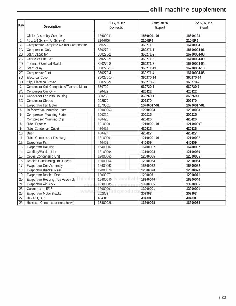
5.30
chill machine supplement
Key Description
Chiller Assembly Complete 16600041 16600041-01 166001981 #8 x 3/8 Screw (All Screws) 210-8R6 210-8R6 210-8R62 Compressor Complete w/Start Components 360270 360271 16700004
2A Compressor Only 360270-1 360271-1 16700004-012B Start Capacitor 360270-2 360271-2 16700004-082C Capacitor End Cap 360270-5 360271-3 16700004-092D Thermal Overload Switch 360270-8 360271-8 16700004-042E Start Relay 360270-11 360271-11 16700004-102F Compressor Foot 360270-4 360271-4 16700004-053G Electrical Cover 360270-14 360270-14 360270-143H Clip, Electrical Cover 360270-9 360270-9 360270-93 Condenser Coil Complete w/Fan and Motor 660720 660720-1 660720-1
3A Condenser Coil Only 420422 420422 4204223B Condenser Fan with Housing 360269 360269-1 360269-13C Condenser Shroud 202879 202879 2028794 Evaporator Fan Motor 16700017 16700017-01 16700017-015 Refrigeration Mounting Plate 12000063 12000063 120000636 Compressor Mounting Plate 300225 300225 3002257 Compressor Mounting Clip 420426 420426 4204268 Tube, Process 12100001 12100001-01 1210000079 Tube Condenser Outlet 420428 420428 42042810 Drier 420427 420427 42042711 Tube, Compressor Discharge 12100001 12100001-01 1210000712 Evaporator Pan 440459 440459 44045913 Evaporator Housing 16400002 16400002 1640000214 Capillary/Suction Line 12100004 12100004 1210002015 Cover, Condensing Unit 12000065 12000065 1200006516 Bracket Condensing Unit Cover 12000064 12000064 1200006417 Evaporator Coil Assembly 16600062 16600062 1660006218 Evaporator Bracket Rear 12000070 12000070 1200007019 Evaporator Bracket Front 12000071 12000071 1200007120 Evaporator Housing, Top Assembly 16600040 16600040 1660004021 Evaporator Air Block 13300005 13300005 1330000525 Gasket, 1/4 x 5/16 13000001 13000001 1300000126 Evaporator Motor Bracket 202893 202893 20289327 Hex Nut, 8-32 404-08 404-08 404-0828 Harness, Compressor (not shown) 16800028 16800028 16800058
117V, 60 HzDomestic
230V, 50 HzExport
220V, 60 HzBrazil

5.31
123 trim
Top Trim
Window Trim Vertical
Delivery Door Trim
Window TrimHorizontal
Bottom Trim
Trim OutsideVertical

5.32
123 trim
Aw
ard
CP
3
Ste
rling
, M
issi
on
Tron
Gen
esis
Apo
llo
Eur
o -
Gre
y
Eur
o -
Bla
ck
Ara
mar
k
Van
tage
AP
II
VIP
Top Trim Part # DimensionsSilver, use with insert 340042-8 1 1 1 2 3/4 x 36.890Black 340055-9 1 Length 36.890Black, use with insert 340042-10 1 2 3/4 x 36.890
340044-9 1Silver, use with insert 340044-4 1 1.798 x 36.890Silver w Black tape 660231-3 2 Length 36.890Silver, use with insert 340044-11 1 1 1 1.798 x 26.997
Trim Outside Vertical Part # LengthSilver 340057 2 2 2 2 65 39/64Black 340057-2 2 2 2 65 39/64Silver Taped 660231-20 2 65 39/64
Window Trim Horizontal Part # LengthSilver 340058 1 1 1 1 1 26.721Black 340058-5 1 1 1 26.721Black 340062-3 1 1 26.997Clear 340062-2 1 26.697
340058-46
Window Trim Vertical Part # LengthSilver 340058-7 2 2 51.531Silver 340058-2 2 52.468Silver 340058-4 2 50.937Black 340058-6 2 2 51.531Black 340058-8 2 50.937
340058-46 2Silver 340062 2 2 65.406Black 340062-1 2 65.406
Delivery Door Trim Part # LengthSilver 340055-3 1 1 36.89Black 340055-9 1 1 36.89Silver w Black tape 660231-3 1 1 36.89Black 340062-3 1 1 26.997Clear 340062-2 1 26.997
340058-5 1
Bottom Trim Part # LengthSilver w Black tape 660231-3 1 1 1 36.89Black, Square 340055-9 36.89Door Vinyl Edge Trim 201678-5 1 1 1 27 3/16Door Vinyl Edge Trim 201678-2 1 1 1 1 37 57/64Door Vinyl Edge Trim 201678 1
123 Trim
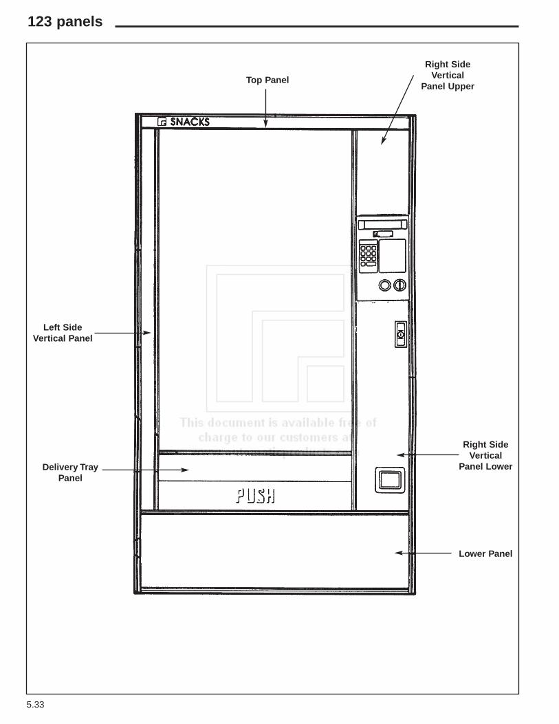
5.33
123 panels
Top Panel
Lower Panel
Right SideVertical
Panel Lower
Right SideVertical
Panel Upper
Left SideVertical Panel
Delivery TrayPanel
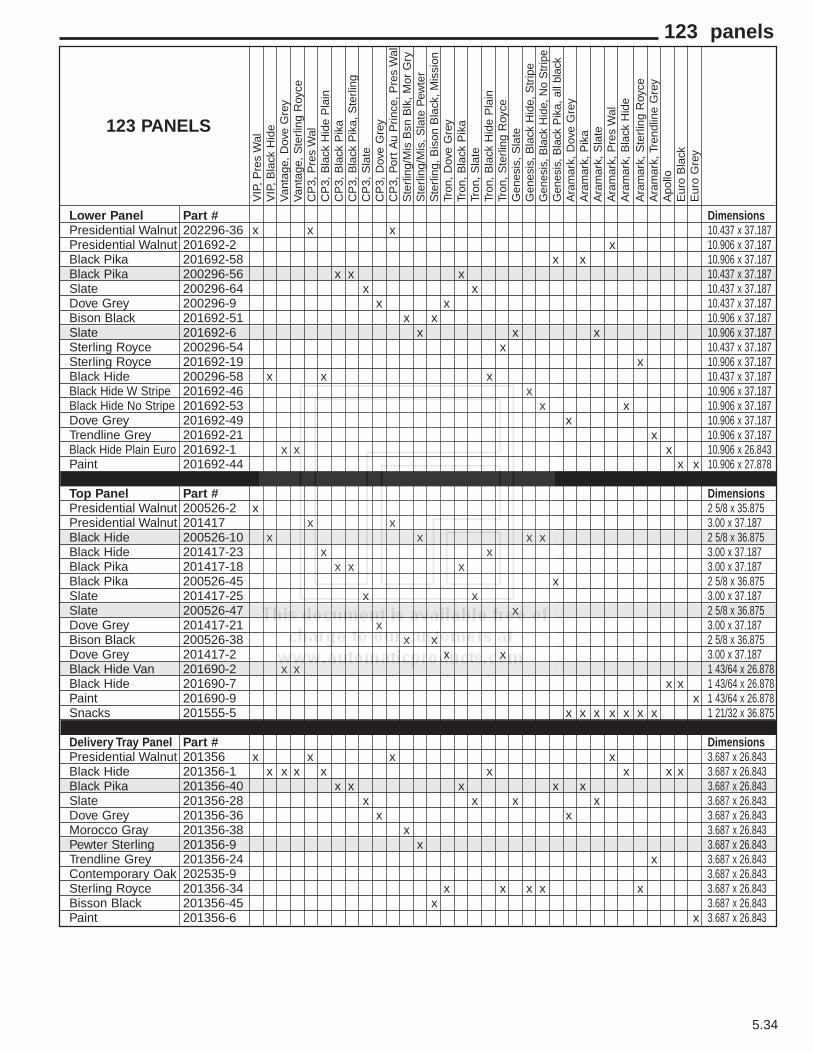
5.34
123 panels
VIP
, P
res
Wal
VIP
, B
lack
Hid
eV
anta
ge,
Dov
e G
rey
Van
tage
, S
terli
ng R
oyce
CP
3, P
res
Wal
CP
3, B
lack
Hid
e P
lain
CP
3, B
lack
Pik
aC
P3,
Bla
ck P
ika,
Ste
rling
CP
3, S
late
CP
3, D
ove
Gre
yC
P3,
Por
t A
u P
rince
, P
res
Wal
Ste
rling
/Mis
Bsn
Blk
, M
or G
ryS
terli
ng/M
is,
Sla
te P
ewte
rS
terli
ng,
Bis
on B
lack
, M
issi
onTr
on,
Dov
e G
rey
Tron
, B
lack
Pik
aTr
on,
Sla
teTr
on,
Bla
ck H
ide
Pla
inTr
on,
Ste
rling
Roy
ceG
enes
is,
Sla
teG
enes
is,
Bla
ck H
ide,
Str
ipe
Gen
esis
, Bla
ck H
ide,
No
Str
ipe
Gen
esis
, Bla
ck P
ika,
all
blac
kA
ram
ark,
Dov
e G
rey
Ara
mar
k, P
ika
Ara
mar
k, S
late
Ara
mar
k, P
res
Wal
Ara
mar
k, B
lack
Hid
eA
ram
ark,
Ste
rling
Roy
ceA
ram
ark,
Tre
ndlin
e G
rey
Apo
lloE
uro
Bla
ckE
uro
Gre
y
Lower Panel Part # DimensionsPresidential Walnut 202296-36 x x x 10.437 x 37.187Presidential Walnut 201692-2 x 10.906 x 37.187Black Pika 201692-58 x x 10.906 x 37.187Black Pika 200296-56 x x x 10.437 x 37.187Slate 200296-64 x x 10.437 x 37.187Dove Grey 200296-9 x x 10.437 x 37.187Bison Black 201692-51 x x 10.906 x 37.187Slate 201692-6 x x x 10.906 x 37.187Sterling Royce 200296-54 x 10.437 x 37.187Sterling Royce 201692-19 x 10.906 x 37.187Black Hide 200296-58 x x x 10.437 x 37.187Black Hide W Stripe 201692-46 x 10.906 x 37.187Black Hide No Stripe 201692-53 x x 10.906 x 37.187Dove Grey 201692-49 x 10.906 x 37.187Trendline Grey 201692-21 x 10.906 x 37.187Black Hide Plain Euro 201692-1 x x x 10.906 x 26.843Paint 201692-44 x x 10.906 x 27.878
Top Panel Part # DimensionsPresidential Walnut 200526-2 x 2 5/8 x 35.875Presidential Walnut 201417 x x 3.00 x 37.187Black Hide 200526-10 x x x x 2 5/8 x 36.875Black Hide 201417-23 x x 3.00 x 37.187Black Pika 201417-18 x x x 3.00 x 37.187Black Pika 200526-45 x 2 5/8 x 36.875Slate 201417-25 x x 3.00 x 37.187Slate 200526-47 x 2 5/8 x 36.875Dove Grey 201417-21 x 3.00 x 37.187Bison Black 200526-38 x x 2 5/8 x 36.875Dove Grey 201417-2 x x 3.00 x 37.187Black Hide Van 201690-2 x x 1 43/64 x 26.878Black Hide 201690-7 x x 1 43/64 x 26.878Paint 201690-9 x 1 43/64 x 26.878Snacks 201555-5 x x x x x x x 1 21/32 x 36.875
Delivery Tray Panel Part # DimensionsPresidential Walnut 201356 x x x x 3.687 x 26.843Black Hide 201356-1 x x x x x x x x 3.687 x 26.843Black Pika 201356-40 x x x x x 3.687 x 26.843Slate 201356-28 x x x x 3.687 x 26.843Dove Grey 201356-36 x x 3.687 x 26.843Morocco Gray 201356-38 x 3.687 x 26.843Pewter Sterling 201356-9 x 3.687 x 26.843Trendline Grey 201356-24 x 3.687 x 26.843Contemporary Oak 202535-9 3.687 x 26.843Sterling Royce 201356-34 x x x x x 3.687 x 26.843Bisson Black 201356-45 x 3.687 x 26.843Paint 201356-6 x 3.687 x 26.843
123 PANELS

5.35
123 panels
Top Panel
Lower Panel
Right SideVertical
Panel Lower
Right SideVertical
Panel Upper
Left SideVertical Panel
Delivery TrayPanel
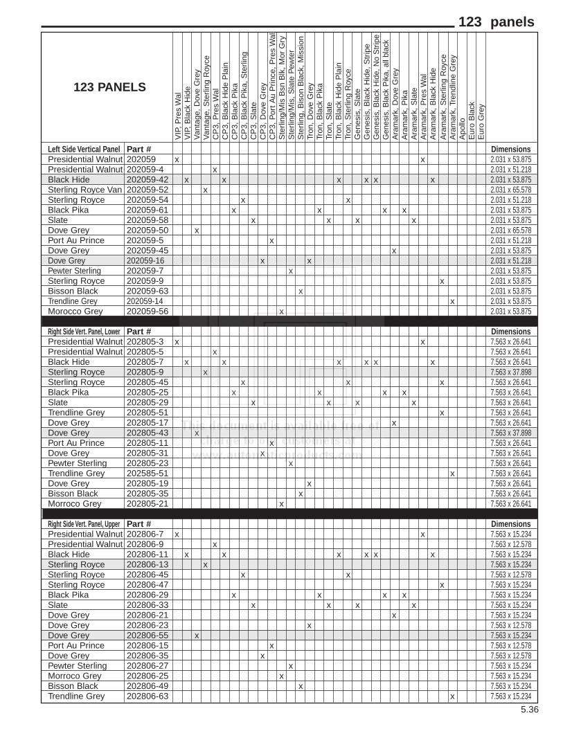
5.36
123 panels
VIP
, P
res
Wal
VIP
, B
lack
Hid
eV
anta
ge,
Dov
e G
rey
Van
tage
, S
terli
ng R
oyce
CP
3, P
res
Wal
CP
3, B
lack
Hid
e P
lain
CP
3, B
lack
Pik
aC
P3,
Bla
ck P
ika,
Ste
rling
CP
3, S
late
CP
3, D
ove
Gre
yC
P3,
Por
t A
u P
rince
, P
res
Wal
Ste
rling
/Mis
Bsn
Blk
, M
or G
ryS
terli
ng/M
is,
Sla
te P
ewte
rS
terli
ng,
Bis
on B
lack
, M
issi
onTr
on,
Dov
e G
rey
Tron
, B
lack
Pik
aTr
on,
Sla
teTr
on,
Bla
ck H
ide
Pla
inTr
on,
Ste
rling
Roy
ceG
enes
is,
Sla
teG
enes
is,
Bla
ck H
ide,
Str
ipe
Gen
esis
, Bla
ck H
ide,
No
Str
ipe
Gen
esis
, Bla
ck P
ika,
all
blac
kA
ram
ark,
Dov
e G
rey
Ara
mar
k, P
ika
Ara
mar
k, S
late
Ara
mar
k, P
res
Wal
Ara
mar
k, B
lack
Hid
eA
ram
ark,
Ste
rling
Roy
ceA
ram
ark,
Tre
ndlin
e G
rey
Apo
lloE
uro
Bla
ckE
uro
Gre
y
Left Side Vertical Panel Part # DimensionsPresidential Walnut 202059 x x 2.031 x 53.875Presidential Walnut 202059-4 x 2.031 x 51.218Black Hide 202059-42 x x x x x x 2.031 x 53.875Sterling Royce Van 202059-52 x 2.031 x 65.578Sterling Royce 202059-54 x x 2.031 x 51.218Black Pika 202059-61 x x x x 2.031 x 53.875Slate 202059-58 x x x x 2.031 x 53.875Dove Grey 202059-50 x 2.031 x 65.578Port Au Prince 202059-5 x 2.031 x 51.218Dove Grey 202059-45 x 2.031 x 53.875Dove Grey 202059-16 x x 2.031 x 51.218Pewter Sterling 202059-7 x 2.031 x 53.875Sterling Royce 202059-9 x 2.031 x 53.875Bisson Black 202059-63 x 2.031 x 53.875Trendline Grey 202059-14 x 2.031 x 53.875Morocco Grey 202059-56 x 2.031 x 53.875
Right Side Vert. Panel, Lower Part # DimensionsPresidential Walnut 202805-3 x x 7.563 x 26.641Presidential Walnut 202805-5 x 7.563 x 26.641Black Hide 202805-7 x x x x x x 7.563 x 26.641Sterling Royce 202805-9 x 7.563 x 37.898Sterling Royce 202805-45 x x x 7.563 x 26.641Black Pika 202805-25 x x x x 7.563 x 26.641Slate 202805-29 x x x x 7.563 x 26.641Trendline Grey 202805-51 x 7.563 x 26.641Dove Grey 202805-17 x 7.563 x 26.641Dove Grey 202805-43 x 7.563 x 37.898Port Au Prince 202805-11 x 7.563 x 26.641Dove Grey 202805-31 x 7.563 x 26.641Pewter Sterling 202805-23 x 7.563 x 26.641Trendline Grey 202585-51 x 7.563 x 26.641Dove Grey 202805-19 x 7.563 x 26.641Bisson Black 202805-35 x 7.563 x 26.641Morroco Grey 202805-21 x 7.563 x 26.641
Right Side Vert. Panel, Upper Part # DimensionsPresidential Walnut 202806-7 x x 7.563 x 15.234Presidential Walnut 202806-9 x 7.563 x 12.578Black Hide 202806-11 x x x x x x 7.563 x 15.234Sterling Royce 202806-13 x 7.563 x 15.234Sterling Royce 202806-45 x x 7.563 x 12.578Sterling Royce 202806-47 x 7.563 x 15.234Black Pika 202806-29 x x x x 7.563 x 15.234Slate 202806-33 x x x x 7.563 x 15.234Dove Grey 202806-21 x 7.563 x 15.234Dove Grey 202806-23 x 7.563 x 12.578Dove Grey 202806-55 x 7.563 x 15.234Port Au Prince 202806-15 x 7.563 x 12.578Dove Grey 202806-35 x 7.563 x 12.578Pewter Sterling 202806-27 x 7.563 x 15.234Morroco Grey 202806-25 x 7.563 x 15.234Bisson Black 202806-49 x 7.563 x 15.234Trendline Grey 202806-63 x 7.563 x 15.234
123 PANELS
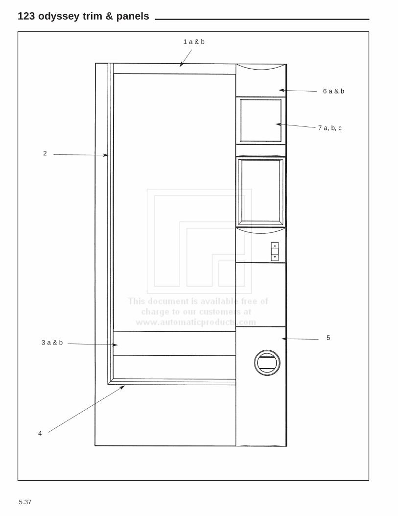
5.37
123 odyssey trim & panels
7 a, b, c
6 a & b
5
4
2
3 a & b
1 a & b
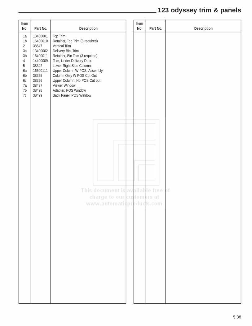
ItemNo. Part No. Description
1a 13400001 Top Trim 1b 16400010 Retainer, Top Trim (3 required) 2 38647 Vertical Trim 3a 13400002 Delivery Bin, Trim 3b 16400011 Retainer, Bin Trim (3 required) 4 14400009 Trim, Under Delivery Door.5 38342 Lower Right Side Column.6a 16600111 Upper Column W POS, Assembly.6b 38355 Column Only W POS Cut Out 6c 38356 Upper Column, No POS Cut out 7a 38497 Viewer Window 7b 38498 Adapter, POS Window 7c 38499 Back Panel, POS Window
ItemNo. Part No. Description
5.38
123 odyssey trim & panels

5.39
connectors
4 PIN INTERNATIONAL MOLEX PLUG 380296
3 PIN INTERNATIONAL MOLEX PLUGFREE HANGING - 380286PANEL MOUNT - 380286-1
4 PIN INTERNATIONAL MOLEXRECEPTICAL - 380293
3 PIN INTERNATIONAL MOLEXRECEPTICAL - 380288
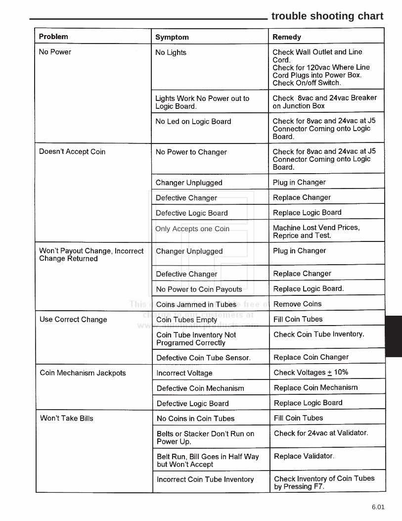
6.01
trouble shooting chart
Only Accepts one Coin

6.02
trouble shooting chart
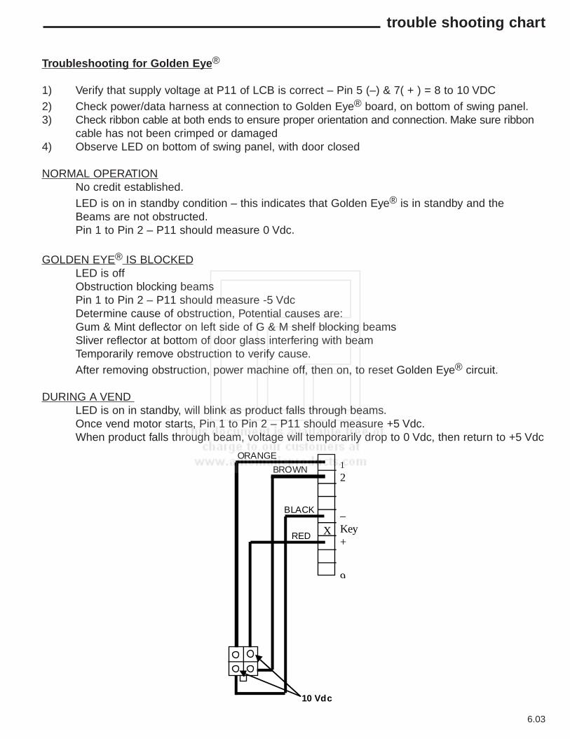
6.03
RED
BLACK
BROWN
ORANGE
X
1
2
–Key+
9
10 Vdc
Troubleshooting for Golden Eye®
1) Verify that supply voltage at P11 of LCB is correct – Pin 5 (–) & 7( + ) = 8 to 10 VDC2) Check power/data harness at connection to Golden Eye® board, on bottom of swing panel.3) Check ribbon cable at both ends to ensure proper orientation and connection. Make sure ribbon
cable has not been crimped or damaged4) Observe LED on bottom of swing panel, with door closed
NORMAL OPERATIONNo credit established.LED is on in standby condition – this indicates that Golden Eye® is in standby and theBeams are not obstructed.Pin 1 to Pin 2 – P11 should measure 0 Vdc.
GOLDEN EYE® IS BLOCKEDLED is offObstruction blocking beamsPin 1 to Pin 2 – P11 should measure -5 VdcDetermine cause of obstruction, Potential causes are:Gum & Mint deflector on left side of G & M shelf blocking beamsSliver reflector at bottom of door glass interfering with beamTemporarily remove obstruction to verify cause.After removing obstruction, power machine off, then on, to reset Golden Eye® circuit.
DURING A VEND LED is on in standby, will blink as product falls through beams.Once vend motor starts, Pin 1 to Pin 2 – P11 should measure +5 Vdc.When product falls through beam, voltage will temporarily drop to 0 Vdc, then return to +5 Vdc
trouble shooting chart
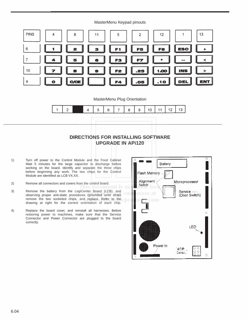
DIRECTIONS FOR INSTALLING SOFTWARE UPGRADE IN APi120
1) Turn off power to the Control Module and the Food CabinetWait 5 minutes for the large capacitor to discharge beforeworking on the board. Identify and separate the three chipsbefore beginning any work. The two chips for the ControlModule are identified as LCB VX.XX.
2) Remove all connectors and covers from the control board.
3) Remove the battery from the LogiCenter Board (LCB), andobserving proper anti-static procedures (grounded wrist strap)remove the two socketed chips, and replace. Refer to thedrawing at right for the correct orientation of each chip.
4) Replace the board cover, and reinstall all harnesses. Beforerestoring power to machines, make sure that the ServiceConnector and Power Connector are plugged to the boardcorrectly.
MasterMenu Keypad pinouts
MasterMenu Plug Orientation
6.04

6.05
Control Board Installation Instructions(For Lcb part’s 360251 & 360274)
When installing this board into any machine it is necessary that the board be reset to factory defaults.
Instructions to reset the board are as follows:
Install the board into the machine and reconnect all the harnesses and power up the machine.
1. Open Machine/Tower door.The display should say Enter for MasterMenu.
2. Press Enter.3. Press the > until the display indicates Security.4. Press Enter 5. The display will indicate Machine ID, press the < one time and the display will indicate
Machine Reset - N.6. Press the + key the display will indicate Machine Reset machine - Y.7. Press the Enter key, The display will indicate Reset - Messages.8. Press the + key until the display indicates Reset - All.9. Press Enter, the key and the display will indicate Are you Sure - N.10. Press the + key and the display will indicate Are you Sure - Y.11. Press the Enter key and board will beep and the display will default to Machine Reset - N.
The Board has now been set to factory default.12. See quick set up reference page in the Service Manual for Instructions on programming the
Control Board.13. Open and close door on the 120 to scan selections.
CAUTION: THE FOLLOWING PROCEDURES REQUIRESTHAT ANTI-STATIC PRECAUTIONS MUST BE TAKEN OR
DAMAGE TO THE CONTROL BOARD MAY RESULT!
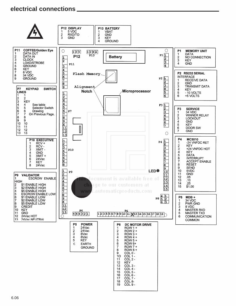
6.06
electrical connections

notes

notes