Automatic ower factor regulators - Lightning …...Automatic power factor regulators R1-6 References...
20
Automatic power factor regulators Unit 6/22 Moselle Ave, Henderson, Auckland, New Zealand PO Box 21-872, Henderson, Auckland, New Zealand Phone:+64 9 833 5749 Email:[email protected] Web: www.LPINZ.co.nz NEW ZEALAND WWW.LPINZ.CO.NZ
Transcript of Automatic ower factor regulators - Lightning …...Automatic power factor regulators R1-6 References...
Automatic power factor regulators
Unit 6/22 Moselle Ave, Henderson, Auckland, New Zealand PO Box 21-872, Henderson, Auckland, New Zealand
Phone:+64 9 833 5749Email:[email protected]
Web: www.LPINZ.co.nzNEW ZEALANDWWW.LPINZ.CO.NZ
R1-2
Automatic power factor reguladorscomputer Plus-TIntelligent regulator · · · · · · · · · · · · · · · · · · · · · · · · · · · · · · · · · · · · · · · · · · · · · · · · · · · · · · · · · · · · · · · · · · · · · · · · · · · · · · · · · · · · · · · · · R1-5
computer MAXAutomatic power factor regulator · · · · · · · · · · · · · · · · · · · · · · · · · · · · · · · · · · · · · · · · · · · · · · · · · · · · · · · · · · · · · · · · · · · · · · · · · · · · · · · R1-7
computer SmartAutomatic power factor regulator · · · · · · · · · · · · · · · · · · · · · · · · · · · · · · · · · · · · · · · · · · · · · · · · · · · · · · · · · · · · · · · · · · · · · · · · · · · · · · · R1-9
computer plus-TFFast power factor regulator (Static capacitor banks) · · · · · · · · · · · · · · · · · · · · · · · · · · · · · · · · · · · · · · · · · · · · · · · · · · · · · · · · · · · · · · · ·R1-11
computer MAX-fFast power factor regulator (Static capacitor banks) · · · · · · · · · · · · · · · · · · · · · · · · · · · · · · · · · · · · · · · · · · · · · · · · · · · · · · · · · · · · · · · R1-13
computer Smart fastAutomatic power factor regulator (Static capacitor banks) · · · · · · · · · · · · · · · · · · · · · · · · · · · · · · · · · · · · · · · · · · · · · · · · · · · · · · · · · · R1-15
DIR21-step power factor relay. DIN rail · · · · · · · · · · · · · · · · · · · · · · · · · · · · · · · · · · · · · · · · · · · · · · · · · · · · · · · · · · · · · · · · · · · · · · · · · · · · · R1-17
Automatic power factor regulators
R1-3
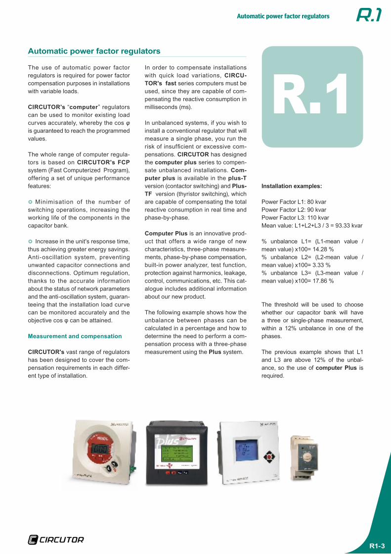
The use of automatic power factor regulators is required for power factor compensation purposes in installations with variable loads.
CIRCUTOR's “computer” regulators can be used to monitor existing load curves accurately, whereby the cos φ is guaranteed to reach the programmed values.
The whole range of computer regula-tors is based on CIRCUTOR's FCP system (Fast Computerized Program), offering a set of unique performance features:
}} Minimisation of the number of switching operations, increasing the working life of the components in the capacitor bank.
}} Increase in the unit's response time, thus achieving greater energy savings. Anti-oscillation system, preventing unwanted capacitor connections and disconnections. Optimum regulation, thanks to the accurate information about the status of network parameters and the anti-oscillation system, guaran-teeing that the installation load curve can be monitored accurately and the objective cos φ can be attained.
Measurement and compensation
CIRCUTOR's vast range of regulators has been designed to cover the com-pensation requirements in each differ-ent type of installation.
Automatic power factor regulators
R.1Installation examples:
Power Factor L1: 80 kvarPower Factor L2: 90 kvarPower Factor L3: 110 kvarMean value: L1+L2+L3 / 3 = 93.33 kvar
% unbalance L1= (L1-mean value /mean value) x100= 14.28 %% unbalance L2= (L2-mean value /mean value) x100= 3.33 %% unbalance L3= (L3-mean value /mean value) x100= 17.86 %
The threshold will be used to choose whether our capacitor bank will have a three or single-phase measurement, within a 12% unbalance in one of the phases.
The previous example shows that L1 and L3 are above 12% of the unbal-ance, so the use of computer Plus is required.
In order to compensate installations with quick load variations, CIRCU-TOR's fast series computers must be used, since they are capable of com-pensating the reactive consumption in milliseconds (ms).
In unbalanced systems, if you wish to install a conventional regulator that will measure a single phase, you run the risk of insufficient or excessive com-pensations. CIRCUTOR has designed the computer plus series to compen-sate unbalanced installations. Com-puter plus is available in the plus-T version (contactor switching) and Plus-TF version (thyristor switching), which are capable of compensating the total reactive consumption in real time and phase-by-phase.
Computer Plus is an innovative prod-uct that offers a wide range of new characteristics, three-phase measure-ments, phase-by-phase compensation, built-in power analyzer, test function, protection against harmonics, leakage, control, communications, etc. This cat-alogue includes additional information about our new product.
The following example shows how the unbalance between phases can be calculated in a percentage and how to determine the need to perform a com-pensation process with a three-phase measurement using the Plus system.
Automatic power factor regulators
R1-4
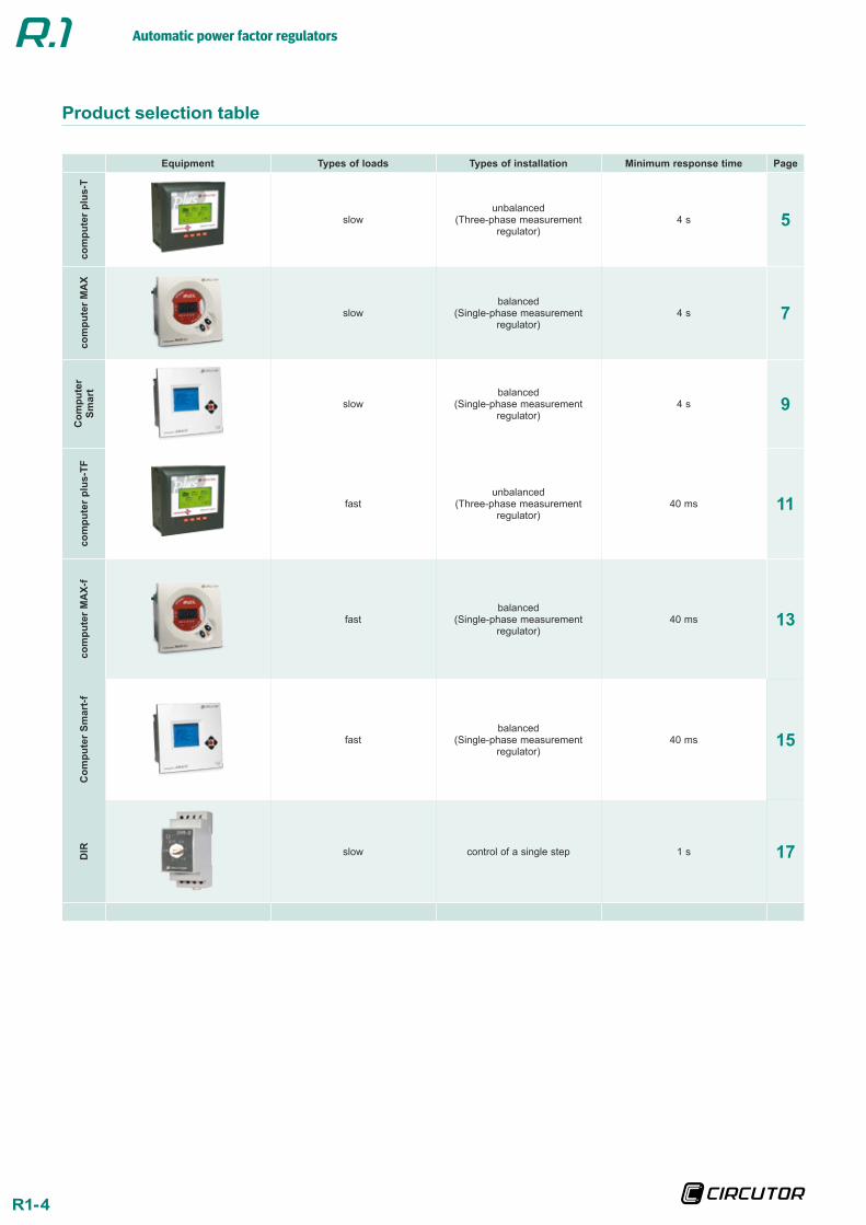
Product selection table
Equipment Types of loads Types of installation Minimum response time Page
com
pute
r pl
us-T
slowunbalanced
(Three-phase measurement regulator)
4 s 5
com
pute
r M
AX
slowbalanced
(Single-phase measurement regulator)
4 s 7
Com
pute
r Sm
art
slowbalanced
(Single-phase measurement regulator)
4 s 9
com
pute
r pl
us-T
F
fastunbalanced
(Three-phase measurement regulator)
40 ms 11
com
pute
r M
AX-
f
fastbalanced
(Single-phase measurement regulator)
40 ms 13
Com
pute
r Sm
art-f
fastbalanced
(Single-phase measurement regulator)
40 ms 15
DIR slow control of a single step 1 s 17
Automatic power factor regulators
R1-5
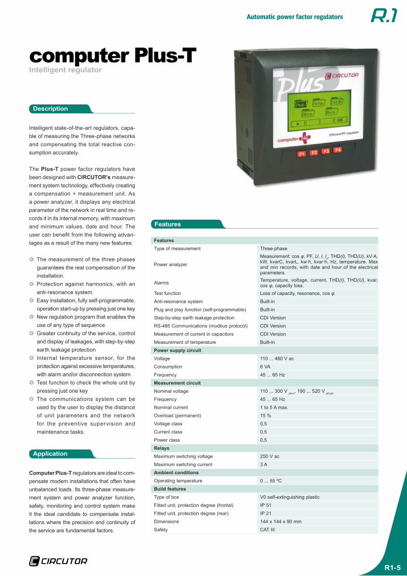
Intelligent regulatorcomputer Plus-T
FeaturesType of measurement Three-phase
Power analyzer
Measurement: cos φ, PF, U, I, In, THD(I), THD(U), kV ·A, kW, kvarC, kvarL, kw ·h, kvar ·h, Hz, temperature. Max and min records, with date and hour of the electrical parameters.
Alarms Temperature, voltage, current, THD(I), THD(U), kvar, cos φ, capacity loss.
Test function Loss of capacity, resonance, cos φ
Anti-resonance system Built-in
Plug and play function (self-programmable) Built-in
Step-by-step earth leakage protection CDI Version
RS-485 Communications (modbus protocol) CDI Version
Measurement of current in capacitors CDI Version
Measurement of temperature Built-in
Power supply circuitVoltage 110 ... 480 V ac
Consumption 6 VA
Frequency 45 ... 65 Hz
Measurement circuitNominal voltage 110 ... 300 V ph-n, 190 ... 520 V ph-ph
Frequency 45 ... 65 Hz
Nominal current 1 to 5 A max.
Overload (permanent) 15 %
Voltage class 0,5
Current class 0,5
Power class 0,5
Relays Maximum switching voltage 250 V ac
Maximum switching current 3 A
Ambient conditionsOperating temperature 0 ... 55 ºC
Build featuresType of box V0 self-extinguishing plastic
Fitted unit, protection degree (frontal) IP 51
Fitted unit, protection degree (rear) IP 21
Dimensions 144 x 144 x 90 mm
Safety CAT III
Intelligent state-of-the-art regulators, capa-ble of measuring the Three-phase networks and compensating the total reactive con-sumption accurately.
The Plus-T power factor regulators have been designed with CIRCUTOR's measure-ment system technology, effectively creating a compensation + measurement unit. As a power analyzer, it displays any electrical parameter of the network in real time and re-cords it in its internal memory, with maximum and minimum values, date and hour. The user can benefit from the following advan-tages as a result of the many new features:
}} The measurement of the three phases guarantees the real compensation of the installation.}} Protection against harmonics, with an anti-resonance system.}} Easy installation, fully self-programmable, operation start-up by pressing just one key}} New regulation program that enables the use of any type of sequence}} Greater continuity of the service, control and display of leakages, with step-by-step earth leakage protection}} Internal temperature sensor, for the protection against excessive temperatures, with alarm and/or disconnection system}} Test function to check the whole unit by pressing just one key}} The communications system can be used by the user to display the distance of unit parameters and the network for the preventive supervision and maintenance tasks.
Application
Computer Plus-T regulators are ideal to com-pensate modern installations that often have unbalanced loads. Its three-phase measure-ment system and power analyzer function, safety, monitoring and control system make it the ideal candidate to compensate instal-lations where the precision and continuity of the service are fundamental factors.
Features
Description
Automatic power factor regulators
R1-6
References
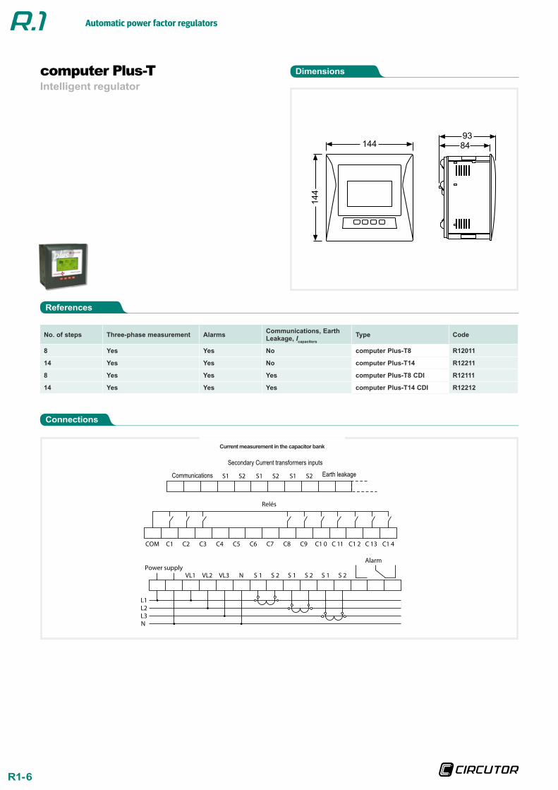
Dimensions
Connections
Intelligent regulatorcomputer Plus-T
No. of steps Three-phase measurement Alarms Communications, Earth Leakage, Icapacitors
Type Code
8 Yes Yes No computer Plus-T8 R12011
14 Yes Yes No computer Plus-T14 R12211
8 Yes Yes Yes computer Plus-T8 CDI R12111
14 Yes Yes Yes computer Plus-T14 CDI R12212
144
14
4
84
93
Current measurement in the capacitor bank
S1 S2 S1 S2 S1 S2
C1 C2 C3 C4 C5 C6 C1 4
Relés
COM
Power supplyVL1 VL2 VL3 N S 1 S 2 S 1 S 2 S 1 S 2
Alarm
L1L2L3N
C7 C8 C9 C1 0 C 11 C1 2 C 13
Secondary Current transformers inputs
Communications Earth leakage
Automatic power factor regulators
R1-7
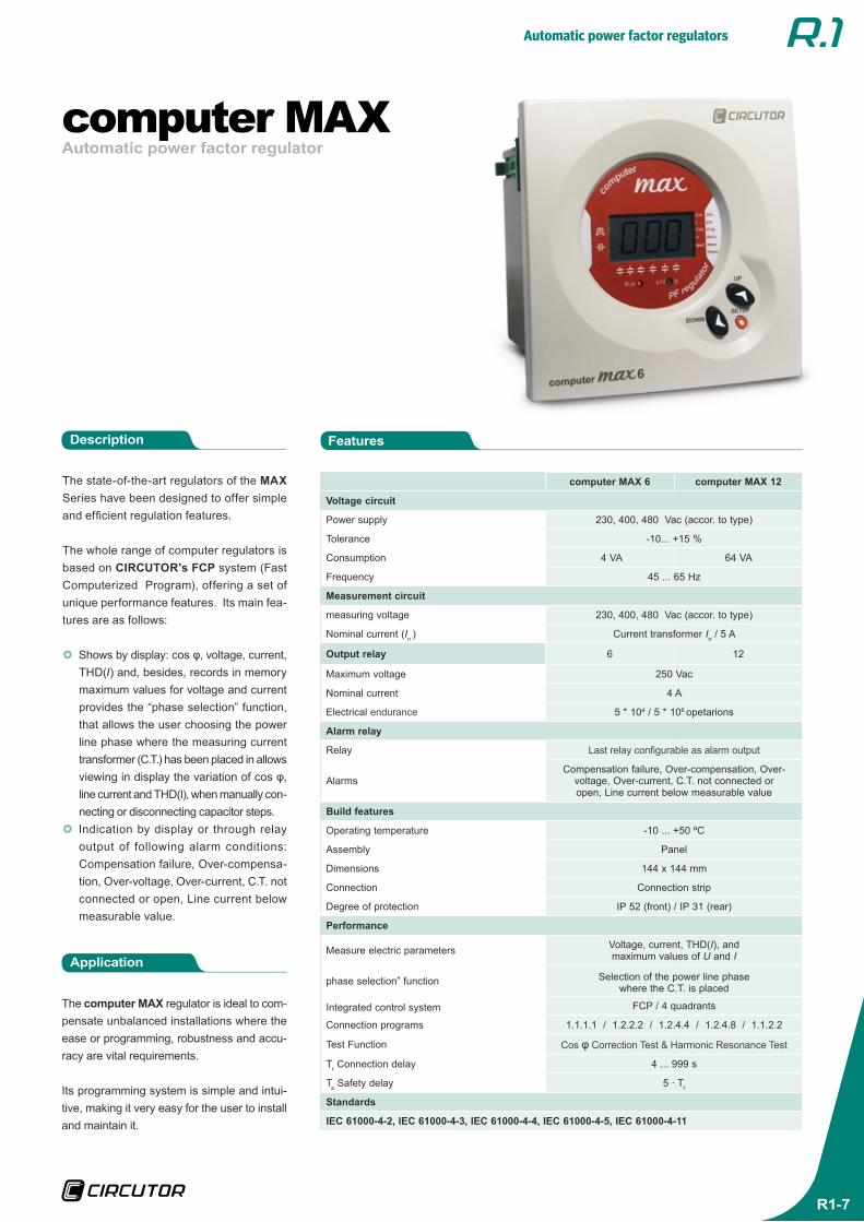
Automatic power factor regulatorcomputer MAX
computer MAX 6 computer MAX 12
Voltage circuit
Power supply 230, 400, 480 Vac (accor. to type)
Tolerance -10... +15 %
Consumption 4 VA 64 VA
Frequency 45 ... 65 Hz
Measurement circuit
measuring voltage 230, 400, 480 Vac (accor. to type)
Nominal current (In ) Current transformer In / 5 A
Output relay 6 12
Maximum voltage 250 Vac
Nominal current 4 A
Electrical endurance 5 * 104 / 5 * 106 opetarions
Alarm relay
Relay Last relay configurable as alarm output
AlarmsCompensation failure, Over-compensation, Over-
voltage, Over-current, C.T. not connected or open, Line current below measurable value
Build features
Operating temperature -10 ... +50 ºC
Assembly Panel
Dimensions 144 x 144 mm
Connection Connection strip
Degree of protection IP 52 (front) / IP 31 (rear)
Performance
Measure electric parameters Voltage, current, THD(I), and maximum values of U and I
phase selection” function Selection of the power line phase where the C.T. is placed
Integrated control system FCP / 4 quadrants
Connection programs 1.1.1.1 / 1.2.2.2 / 1.2.4.4 / 1.2.4.8 / 1.1.2.2
Test Function Cos φ Correction Test & Harmonic Resonance Test
Tr Connection delay 4 ... 999 s
Ts Safety delay 5 · Tr
Standards
IEC 61000-4-2, IEC 61000-4-3, IEC 61000-4-4, IEC 61000-4-5, IEC 61000-4-11
The state-of-the-art regulators of the MAX Series have been designed to offer simple and efficient regulation features.
The whole range of computer regulators is based on CIRCUTOR's FCP system (Fast Computerized Program), offering a set of unique performance features. Its main fea-tures are as follows:
}} Shows by display: cos φ, voltage, current, THD(I) and, besides, records in memory maximum values for voltage and current provides the “phase selection” function, that allows the user choosing the power line phase where the measuring current transformer (C.T.) has been placed in allows viewing in display the variation of cos φ, line current and THD(I), when manually con-necting or disconnecting capacitor steps.}} Indication by display or through relay output of following alarm conditions: Compensation failure, Over-compensa-tion, Over-voltage, Over-current, C.T. not connected or open, Line current below measurable value.
Application
The computer MAX regulator is ideal to com-pensate unbalanced installations where the ease or programming, robustness and accu-racy are vital requirements.
Its programming system is simple and intui-tive, making it very easy for the user to install and maintain it.
FeaturesDescription
Automatic power factor regulators
R1-8
References
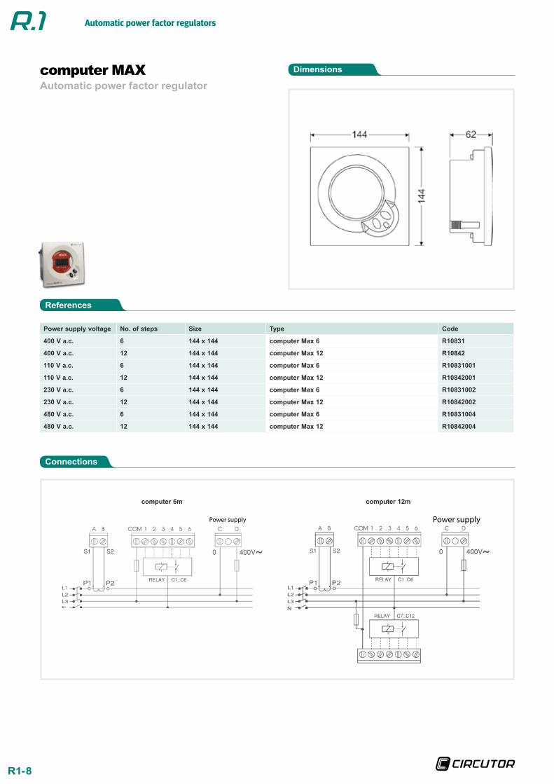
Dimensions
Connections
Automatic power factor regulatorcomputer MAX
Power supply voltage No. of steps Size Type Code
400 V a.c. 6 144 x 144 computer Max 6 R10831
400 V a.c. 12 144 x 144 computer Max 12 R10842
110 V a.c. 6 144 x 144 computer Max 6 R10831001
110 V a.c. 12 144 x 144 computer Max 12 R10842001
230 V a.c. 6 144 x 144 computer Max 6 R10831002
230 V a.c. 12 144 x 144 computer Max 12 R10842002
480 V a.c. 6 144 x 144 computer Max 6 R10831004
480 V a.c. 12 144 x 144 computer Max 12 R10842004
Power supply Power supply
computer 6m computer 12m
Automatic power factor regulators
R1-9
Automatic power factor regulatorcomputer Smart
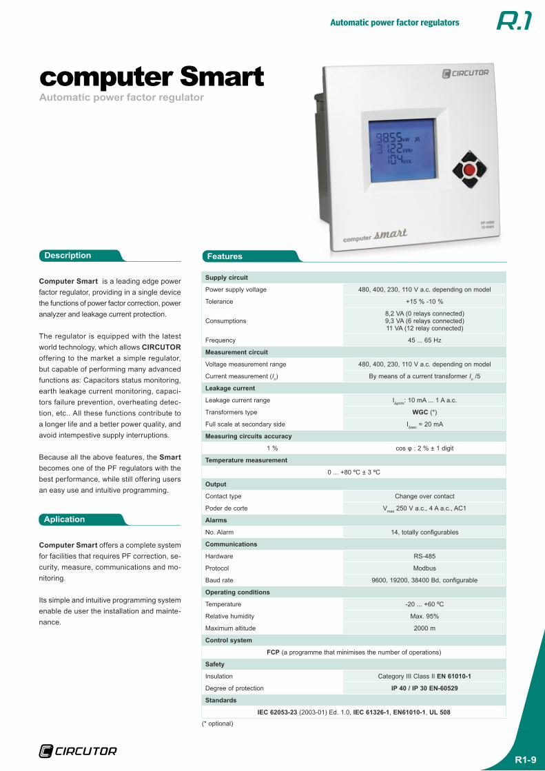
Computer Smart is a leading edge power factor regulator, providing in a single device the functions of power factor correction, power analyzer and leakage current protection.
The regulator is equipped with the latest world technology, which allows CIRCUTOR offering to the market a simple regulator, but capable of performing many advanced functions as: Capacitors status monitoring, earth leakage current monitoring, capaci-tors failure prevention, overheating detec-tion, etc.. All these functions contribute to a longer life and a better power quality, and avoid intempestive supply interruptions.
Because all the above features, the Smart becomes one of the PF regulators with the best performance, while still offering users an easy use and intuitive programming.
Aplication
Computer Smart offers a complete system for facilities that requires PF correction, se-curity, measure, communications and mo-nitoring.
Its simple and intuitive programming system enable de user the installation and mainte-nance.
FeaturesDescription
Supply circuit
Power supply voltage 480, 400, 230, 110 V a.c. depending on model
Tolerance +15 % -10 %
Consumptions8,2 VA (0 relays connected)9,3 VA (6 relays connected)11 VA (12 relay connected)
Frequency 45 ... 65 Hz
Measurement circuit
Voltage measurement range 480, 400, 230, 110 V a.c. depending on model
Current measurement (In) By means of a current transformer In /5
Leakage current
Leakage current range IΔprim: 10 mA ... 1 A a.c.
Transformers type WGC (*)
Full scale at secondary side IΔsec = 20 mA
Measuring circuits accuracy
1 % cos φ : 2 % ± 1 digit
Temperature measurement
0 ... +80 ºC ± 3 ºC
Output
Contact type Change over contact
Poder de corte Vmax 250 V a.c., 4 A a.c., AC1
Alarms
No. Alarm 14, totally configurables
Communications
Hardware RS-485
Protocol Modbus
Baud rate 9600, 19200, 38400 Bd, configurable
Operating conditions
Temperature -20 ... +60 ºC
Relative humidity Max. 95%
Maximum altitude 2000 m
Control system
FCP (a programme that minimises the number of operations)
Safety
Insulation Category III Class II EN 61010-1
Degree of protection IP 40 / IP 30 EN-60529
Standards
IEC 62053-23 (2003-01) Ed. 1.0, IEC 61326-1, EN61010-1, UL 508
(* optional)
Automatic power factor regulators
R1-10
References
Dimensions
Connections
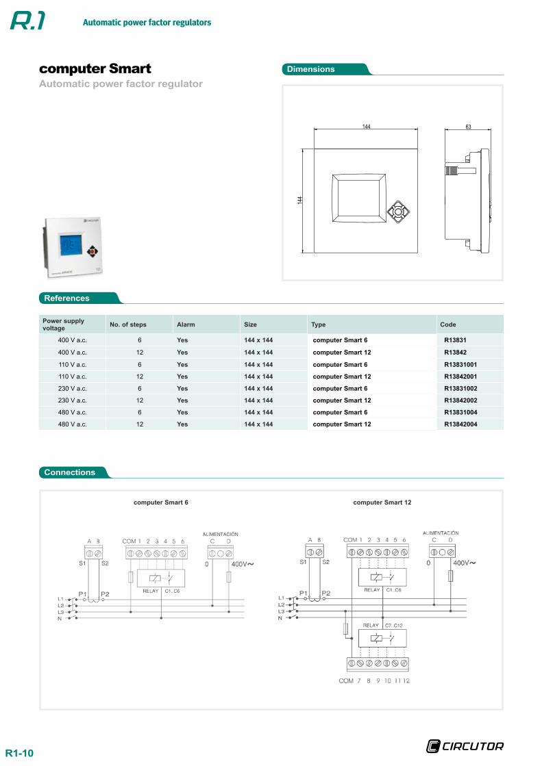
Automatic power factor regulatorcomputer Smart
Power supply voltage No. of steps Alarm Size Type Code
400 V a.c. 6 Yes 144 x 144 computer Smart 6 R13831
400 V a.c. 12 Yes 144 x 144 computer Smart 12 R13842
110 V a.c. 6 Yes 144 x 144 computer Smart 6 R13831001
110 V a.c. 12 Yes 144 x 144 computer Smart 12 R13842001
230 V a.c. 6 Yes 144 x 144 computer Smart 6 R13831002
230 V a.c. 12 Yes 144 x 144 computer Smart 12 R13842002
480 V a.c. 6 Yes 144 x 144 computer Smart 6 R13831004
480 V a.c. 12 Yes 144 x 144 computer Smart 12 R13842004
144
144
63
computer Smart 6 computer Smart 12
Automatic power factor regulators
R1-11
Fast power factor regulator(Static capacitor banks)
computer plus-TF
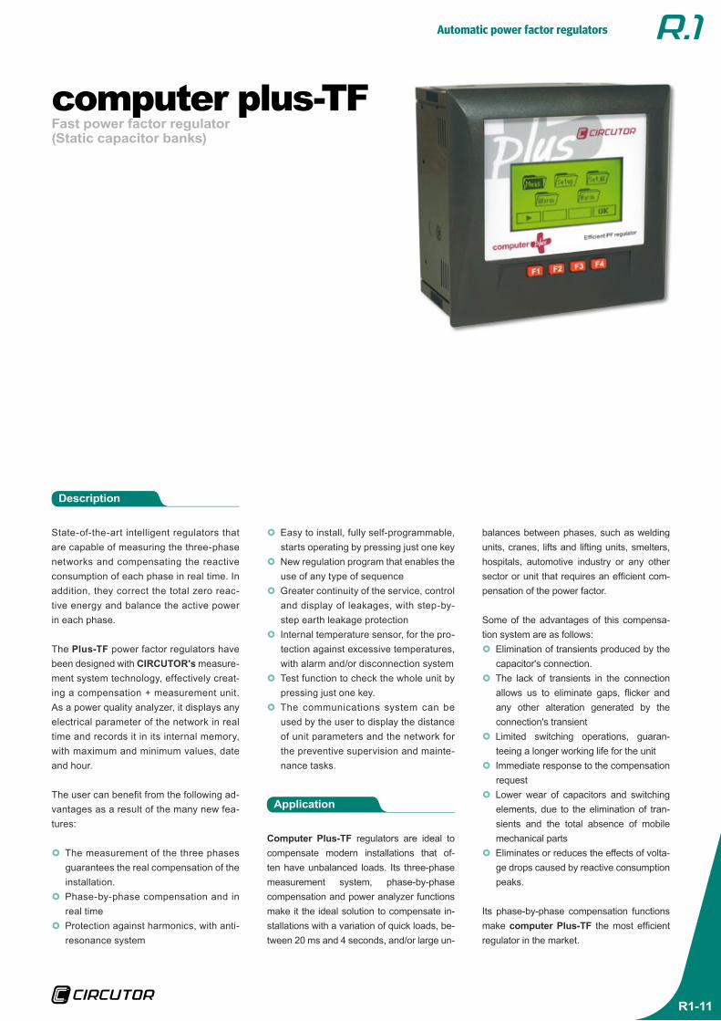
State-of-the-art intelligent regulators that are capable of measuring the three-phase networks and compensating the reactive consumption of each phase in real time. In addition, they correct the total zero reac-tive energy and balance the active power in each phase.
The Plus-TF power factor regulators have been designed with CIRCUTOR's measure-ment system technology, effectively creat-ing a compensation + measurement unit. As a power quality analyzer, it displays any electrical parameter of the network in real time and records it in its internal memory, with maximum and minimum values, date and hour.
The user can benefit from the following ad-vantages as a result of the many new fea-tures:
}} The measurement of the three phases guarantees the real compensation of the installation.}} Phase-by-phase compensation and in real time}} Protection against harmonics, with anti-resonance system
Application
Computer Plus-TF regulators are ideal to compensate modern installations that of-ten have unbalanced loads. Its three-phase measurement system, phase-by-phase compensation and power analyzer functions make it the ideal solution to compensate in-stallations with a variation of quick loads, be-tween 20 ms and 4 seconds, and/or large un-
Description
}} Easy to install, fully self-programmable, starts operating by pressing just one key}} New regulation program that enables the use of any type of sequence}} Greater continuity of the service, control and display of leakages, with step-by-step earth leakage protection}} Internal temperature sensor, for the pro-tection against excessive temperatures, with alarm and/or disconnection system}} Test function to check the whole unit by pressing just one key.}} The communications system can be used by the user to display the distance of unit parameters and the network for the preventive supervision and mainte-nance tasks.
balances between phases, such as welding units, cranes, lifts and lifting units, smelters, hospitals, automotive industry or any other sector or unit that requires an efficient com-pensation of the power factor.
Some of the advantages of this compensa-tion system are as follows:}} Elimination of transients produced by the capacitor's connection.}} The lack of transients in the connection allows us to eliminate gaps, flicker and any other alteration generated by the connection's transient}} Limited switching operations, guaran-teeing a longer working life for the unit}} Immediate response to the compensation request}} Lower wear of capacitors and switching elements, due to the elimination of tran-sients and the total absence of mobile mechanical parts}} Eliminates or reduces the effects of volta-ge drops caused by reactive consumption peaks.
Its phase-by-phase compensation functions make computer Plus-TF the most efficient regulator in the market.
Automatic power factor regulators
R1-12
References
Dimensions
Fast power factor regulator(Static capacitor banks)
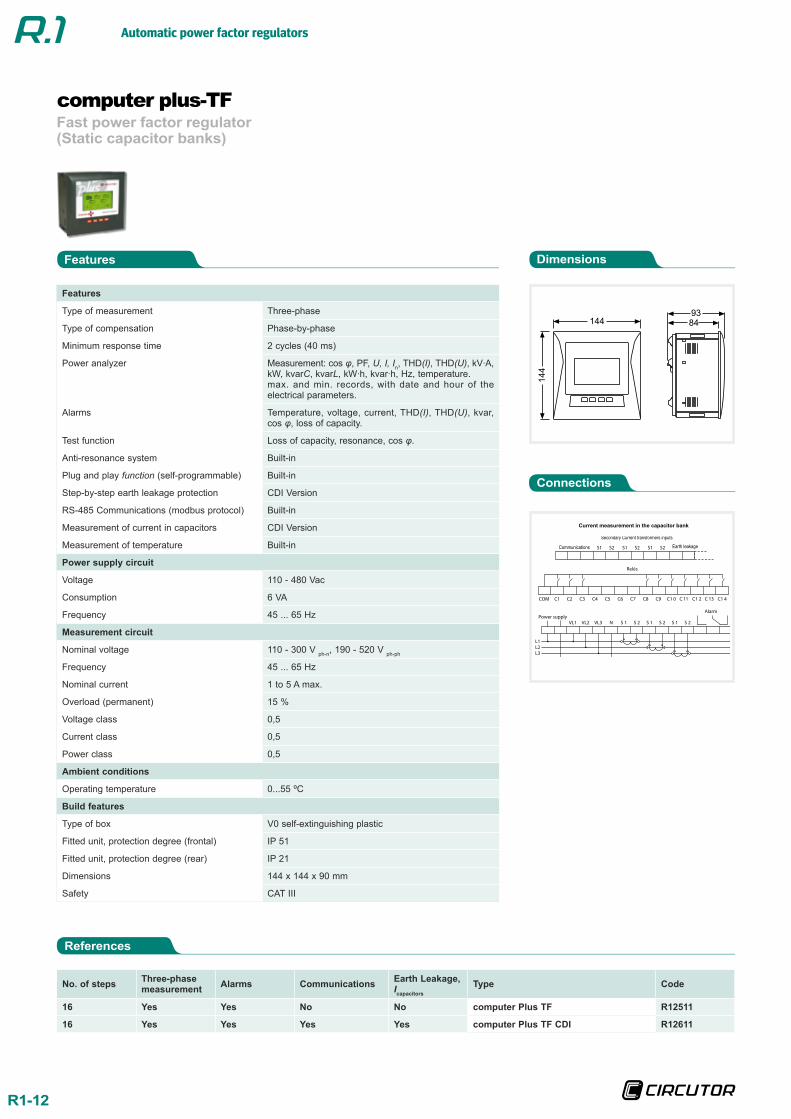
computer plus-TF
No. of steps Three-phase measurement Alarms Communications Earth Leakage,
IcapacitorsType Code
16 Yes Yes No No computer Plus TF R12511
16 Yes Yes Yes Yes computer Plus TF CDI R12611
Features
Features
Type of measurement Three-phase
Type of compensation Phase-by-phase
Minimum response time 2 cycles (40 ms)
Power analyzer Measurement: cos φ, PF, U, I, In, THD(I), THD(U), kV ·A, kW, kvarC, kvarL, kW ·h, kvar ·h, Hz, temperature.max. and min. records, with date and hour of the electrical parameters.
Alarms Temperature, voltage, current, THD(I), THD(U), kvar, cos φ, loss of capacity.
Test function Loss of capacity, resonance, cos φ.
Anti-resonance system Built-in
Plug and play function (self-programmable) Built-in
Step-by-step earth leakage protection CDI Version
RS-485 Communications (modbus protocol) Built-in
Measurement of current in capacitors CDI Version
Measurement of temperature Built-in
Power supply circuit
Voltage 110 - 480 Vac
Consumption 6 VA
Frequency 45 ... 65 Hz
Measurement circuit
Nominal voltage 110 - 300 V ph-n, 190 - 520 V ph-ph
Frequency 45 ... 65 Hz
Nominal current 1 to 5 A max.
Overload (permanent) 15 %
Voltage class 0,5
Current class 0,5
Power class 0,5
Ambient conditions
Operating temperature 0...55 ºC
Build features
Type of box V0 self-extinguishing plastic
Fitted unit, protection degree (frontal) IP 51
Fitted unit, protection degree (rear) IP 21
Dimensions 144 x 144 x 90 mm
Safety CAT III
Connections
144
14
4
84
93
S1 S2 S1 S2 S1 S2
C1 C2 C3 C4 C5 C6 C1 4
Relés
COM
Power supplyVL1 VL2 VL3 N S 1 S 2 S 1 S 2 S 1 S 2
Alarm
L1L2L3N
C7 C8 C9 C1 0 C 11 C1 2 C 13
Secondary Current transformers inputs
Communications Earth leakage
Current measurement in the capacitor bank
Automatic power factor regulators
R1-13
Fast power factor regulator(Static capacitor banks)
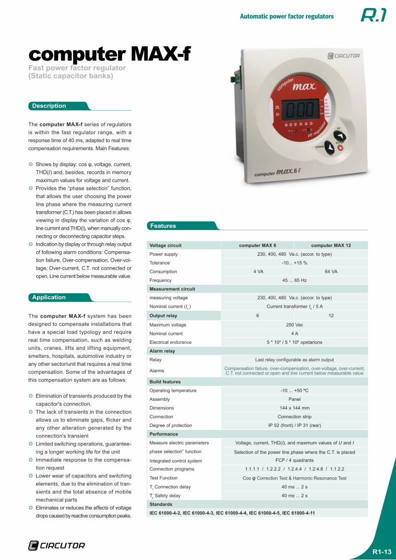
computer MAX-f
The computer MAX-f series of regulators is within the fast regulator range, with a response time of 40 ms, adapted to real time compensation requirements. Main Features:
}} Shows by display: cos φ, voltage, current, THD(I) and, besides, records in memory maximum values for voltage and current.}} Provides the “phase selection” function, that allows the user choosing the power line phase where the measuring current transformer (C.T.) has been placed in allows viewing in display the variation of cos φ, line current and THD(I), when manually con-necting or disconnecting capacitor steps.}} Indication by display or through relay output of following alarm conditions: Compensa-tion failure, Over-compensation, Over-vol-tage, Over-current, C.T. not connected or open, Line current below measurable value.
Application
The computer MAX-f system has been designed to compensate installations that have a special load typology and require real time compensation, such as welding units, cranes, lifts and lifting equipment, smelters, hospitals, automotive industry or any other sector/unit that requires a real time compensation. Some of the advantages of this compensation system are as follows:
}} Elimination of transients produced by the capacitor's connection.}} The lack of transients in the connection allows us to eliminate gaps, flicker and any other alteration generated by the connection's transient}} Limited switching operations, guarantee-ing a longer working life for the unit}} Immediate response to the compensa-tion request}} Lower wear of capacitors and switching elements, due to the elimination of tran-sients and the total absence of mobile mechanical parts}} Eliminates or reduces the effects of voltage drops caused by reactive consumption peaks.
Description
Voltage circuit computer MAX 6 computer MAX 12
Power supply 230, 400, 480 Va.c. (accor. to type)
Tolerance -10... +15 %
Consumption 4 VA 64 VA
Frequency 45 ... 65 Hz
Measurement circuit
measuring voltage 230, 400, 480 Va.c. (accor. to type)
Nominal current (In ) Current transformer In / 5 A
Output relay 6 12
Maximum voltage 250 Vac
Nominal current 4 A
Electrical endurance 5 * 104 / 5 * 106 opetarions
Alarm relay
Relay Last relay configurable as alarm output
Alarms Compensation failure, over-compensation, over-voltage, over-current, C.T. not connected or open and line current below measurable value
Build features
Operating temperature -10 ... +50 ºC
Assembly Panel
Dimensions 144 x 144 mm
Connection Connection strip
Degree of protection IP 52 (front) / IP 31 (rear)
Performance
Measure electric parameters Voltage, current, THD(I), and maximum values of U and I
phase selection” function Selection of the power line phase where the C.T. is placed
Integrated control system FCP / 4 quadrants
Connection programs 1.1.1.1 / 1.2.2.2 / 1.2.4.4 / 1.2.4.8 / 1.1.2.2
Test Function Cos φ Correction Test & Harmonic Resonance Test
Tr Connection delay 40 ms ... 2 s
Ts Safety delay 40 ms ... 2 s
Standards
IEC 61000-4-2, IEC 61000-4-3, IEC 61000-4-4, IEC 61000-4-5, IEC 61000-4-11
Features
Automatic power factor regulators
R1-14
References
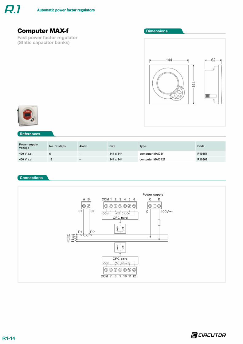
Dimensions
Connections
Fast power factor regulator(Static capacitor banks)
Computer MAX-f
Power supply voltage No. of steps Alarm Size Type Code
400 V a.c. 6 -- 144 x 144 computer MAX 6f R10851
400 V a.c. 12 -- 144 x 144 computer MAX 12f R10862
Automatic power factor regulators
R1-15
Automatic power factor regulator(Static capacitor banks)
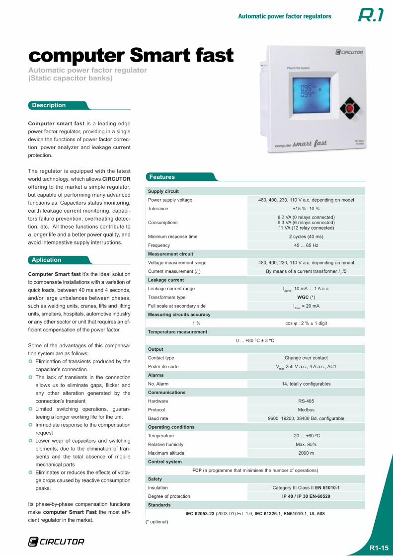
computer Smart fast
Computer smart fast is a leading edge power factor regulator, providing in a single device the functions of power factor correc-tion, power analyzer and leakage current protection.
The regulator is equipped with the latest world technology, which allows CIRCUTOR offering to the market a simple regulator, but capable of performing many advanced functions as: Capacitors status monitoring, earth leakage current monitoring, capaci-tors failure prevention, overheating detec-tion, etc.. All these functions contribute to a longer life and a better power quality, and avoid intempestive supply interruptions.
Aplication
Computer Smart fast it’s the ideal solution to compensate installations with a variation of quick loads, between 40 ms and 4 seconds, and/or large unbalances between phases, such as welding units, cranes, lifts and lifting units, smelters, hospitals, automotive industry or any other sector or unit that requires an ef-ficient compensation of the power factor.
Some of the advantages of this compensa-tion system are as follows:}} Elimination of transients produced by the capacitor’s connection.}} The lack of transients in the connection allows us to eliminate gaps, flicker and any other alteration generated by the connection’s transient}} Limited switching operations, guaran-teeing a longer working life for the unit}} Immediate response to the compensation request}} Lower wear of capacitors and switching elements, due to the elimination of tran-sients and the total absence of mobile mechanical parts}} Eliminates or reduces the effects of volta-ge drops caused by reactive consumption peaks.
Its phase-by-phase compensation functions make computer Smart Fast the most effi-cient regulator in the market.
Features
Description
Supply circuit
Power supply voltage 480, 400, 230, 110 V a.c. depending on model
Tolerance +15 % -10 %
Consumptions8,2 VA (0 relays connected)9,3 VA (6 relays connected)11 VA (12 relay connected)
Minimum response time 2 cycles (40 ms)
Frequency 45 ... 65 Hz
Measurement circuit
Voltage measurement range 480, 400, 230, 110 V a.c. depending on model
Current measurement (In) By means of a current transformer In /5
Leakage current
Leakage current range IΔprim: 10 mA ... 1 A a.c.
Transformers type WGC (*)
Full scale at secondary side IΔsec = 20 mA
Measuring circuits accuracy
1 % cos φ : 2 % ± 1 digit
Temperature measurement
0 ... +80 ºC ± 3 ºC
Output
Contact type Change over contact
Poder de corte Vmax 250 V a.c., 4 A a.c., AC1
Alarms
No. Alarm 14, totally configurables
Communications
Hardware RS-485
Protocol Modbus
Baud rate 9600, 19200, 38400 Bd, configurable
Operating conditions
Temperature -20 ... +60 ºC
Relative humidity Max. 95%
Maximum altitude 2000 m
Control system
FCP (a programme that minimises the number of operations)
Safety
Insulation Category III Class II EN 61010-1
Degree of protection IP 40 / IP 30 EN-60529
Standards
IEC 62053-23 (2003-01) Ed. 1.0, IEC 61326-1, EN61010-1, UL 508
(* optional)
Automatic power factor regulators
R1-16
References
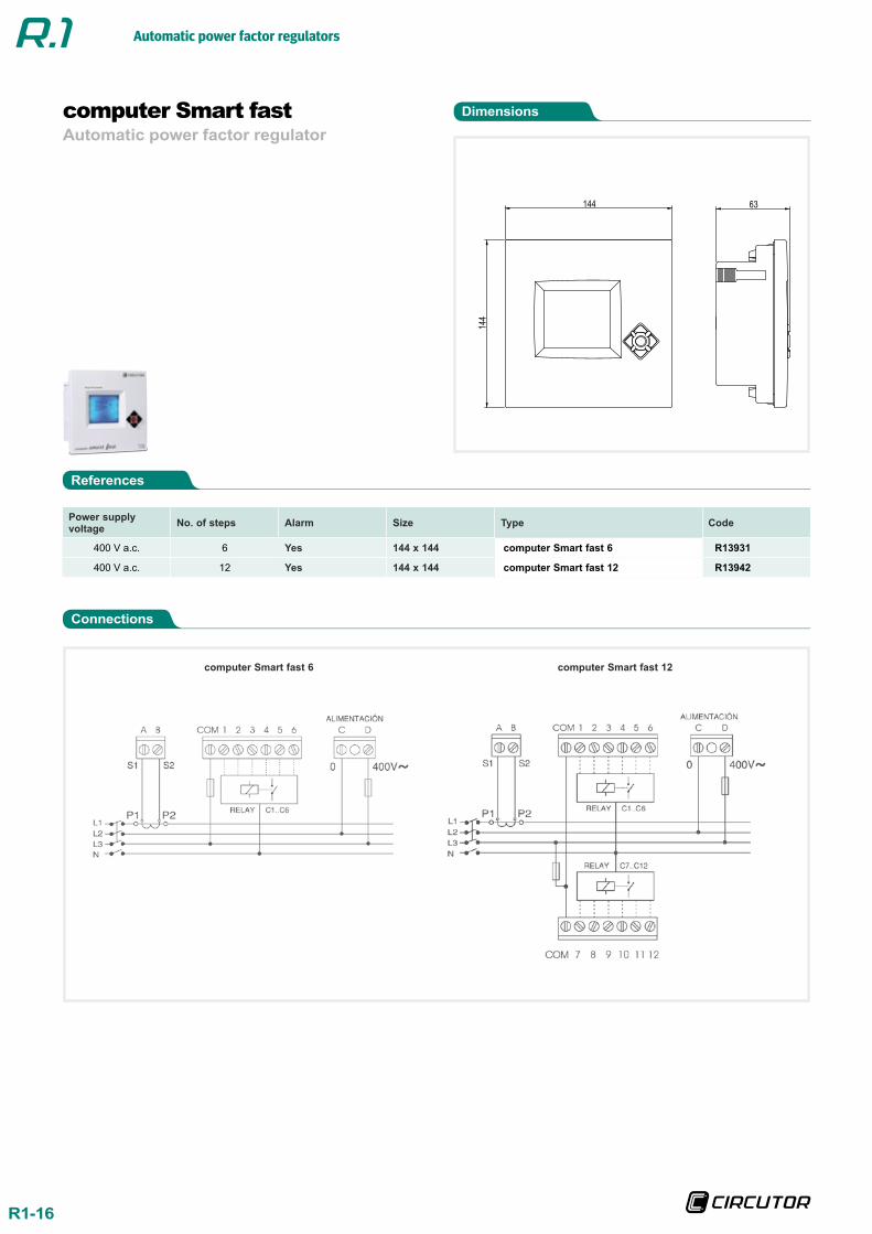
Dimensions
Connections
Automatic power factor regulatorcomputer Smart fast
Power supply voltage No. of steps Alarm Size Type Code
400 V a.c. 6 Yes 144 x 144 computer Smart fast 6 R13931
400 V a.c. 12 Yes 144 x 144 computer Smart fast 12 R13942
144
144
63
computer Smart fast 6 computer Smart fast 12
Automatic power factor regulators
R1-17
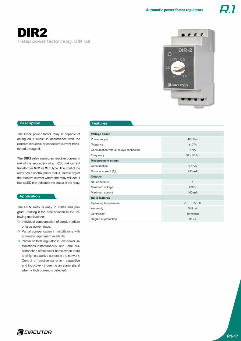
1-step power factor relay. DIN railDIR2
The DIR2 power factor relay is capable of acting on a circuit in accordance with the reactive inductive or capacitive current trans-mitted through it.
The DIR2 relay measures reactive current in mA of the secondary of a .../250 mA current transformer MC1 or MC3 type. The front of the relay has a control panel that is used to adjust the reactive current where the relay will act. It has a LED that indicates the status of the relay.
Application
The DIR2 relay is easy to install and pro-gram, making it the best solution in the fol-lowing applications:}} Individual compensation of small, medium or large power loads.}} Partial compensation in installations with automatic equipment available.}} Partial or total regulator in low-power in-stallations.Instantaneous and total dis-connection of capacitor banks when there is a high capacitive current in the network.Control of reactive currents - capacitive and inductive - triggering an alarm signal when a high current is detected.
FeaturesDescription
Voltage circuit
Power supply 400 Vac
Tolerance ±10 %
Consumption with all relays connected 5 VA
Frequency 50 ~ 50 Hz
Measurement circuit
Consumption 0.5 VA
Nominal current (In ) 250 mA
Outputs
No. of outputs 1
Maximum voltage 200 V
Maximum current 100 mA
Build features
Operating temperature -10 ... +50 ºC
Assembly DIN rail
Connection Terminals
Degree of protection IP 21
Automatic power factor regulators
R1-18
References
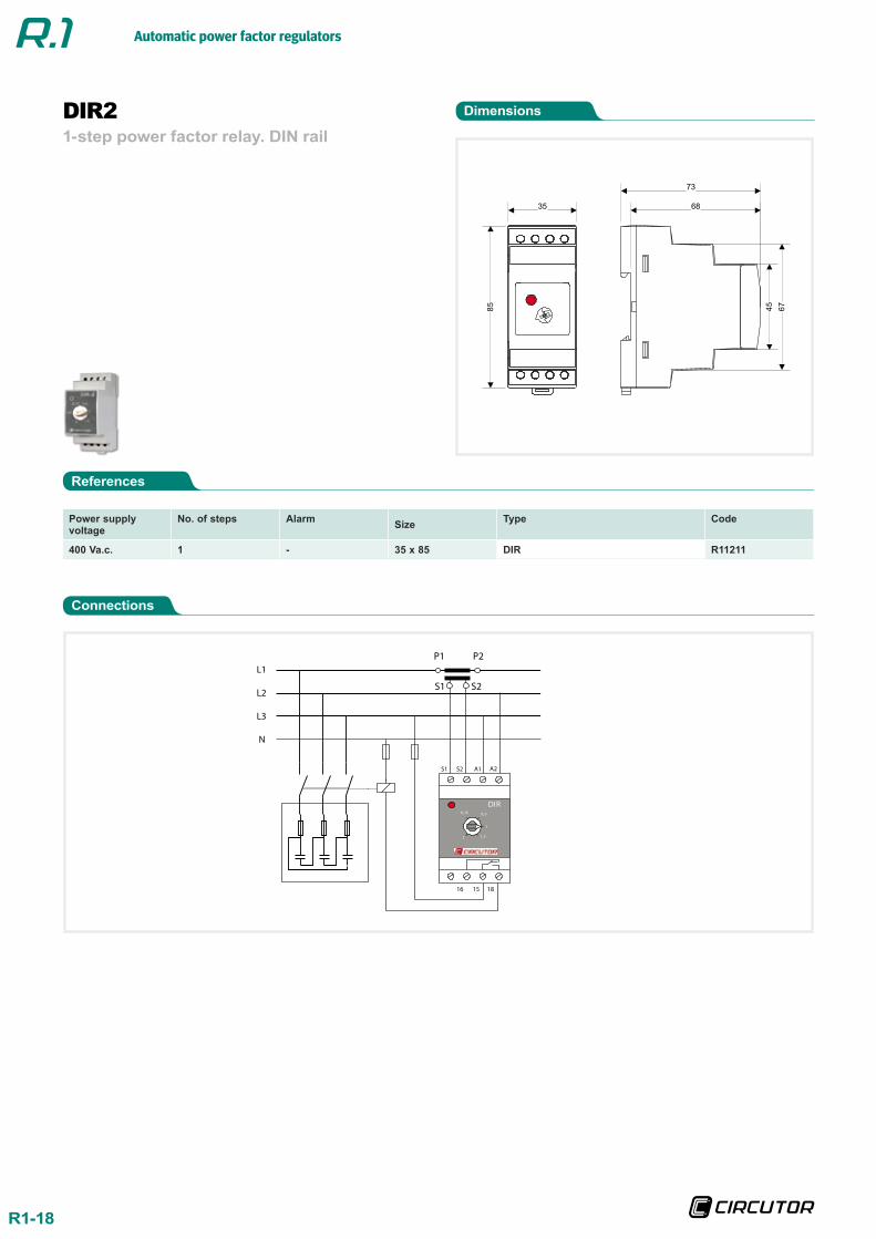
Dimensions
Connections
1-step power factor relay. DIN railDIR2
Power supply voltage
No. of steps Alarm Size Type Code
400 Va.c. 1 - 35 x 85 DIR R11211
L1
L2
L3
N
S1 S2 A1 A2
DIR0,15
2
1
0, 5
1, 5
16 15 18
P1 P2
S1 S2

Automatic power factor regulators
R1-19
R1-20
Automatic power factor reguladors