AutoCrane 2703 Series Owner's Manualautocrane.us/wp-content/uploads/2703-999949-0200.pdf · v use a...
67
OWNERS MANUAL 2703 SERIES REVISION 2/2000 PART NO. 999949 SERIAL NO. __________________________ PO BOX 580697, TULSA, OK 74158-0697 4707 N. MINGO ROAD, TULSA, OK 74117 PHONE (918) 836-0463 SALES FAX (918) 438-6688 SERVICE FAX (918) 834-5979 http://www.autocrane.com
Transcript of AutoCrane 2703 Series Owner's Manualautocrane.us/wp-content/uploads/2703-999949-0200.pdf · v use a...

OWNERS MANUAL2703 SERIESREVISION 2/2000
PART NO. 999949
SERIAL NO. __________________________
PO BOX 580697, TULSA, OK 74158-0697
4707 N. MINGO ROAD, TULSA, OK 74117
PHONE (918) 836-0463
SALES FAX (918) 438-6688 SERVICE FAX (918) 834-5979
http://www.autocrane.com

WARNING! Federal law (49 cfr part 571) requires that the Final Stage Manufacturer ofa vehicle certify that the vehicle complies with all applicable federal regulations. Anymodifications performed on the vehicle prior to the final stage are also consideredintermediate stage manufacturing and must be certified as to compliance. The installer ofthis crane and body is considered one of the manufacturers of the vehicle. As such amanufacturer, the installer is responsible for compliance with all applicable federal andstate regulations, and is required to certify that the vehicle is in compliance.
WARNING! It is the further responsibility of the installer to comply with the OSHATruck Crane Stability Requirements as specified by 29 CFR part 1910.180 (C) (1).
WARNING! NEVER OPERATE THE CRANE NEAR ELECTRICALPOWER LINES! Death or serious injury will result from boom, line, or load contactingelectric lines. Do not use crane within 10 feet (3.05m) of electric power lines carrying up to50,000 volts. One foot additional clearance is required for every additional 30,000 volts or less.
WARNING! NEVER .............................v EXCEED load chart capacities (centerline of rotation to hoist hook).v un-reel last 5 wraps of cable from drum!v wrap cable around load!v attempt to lift or drag a load from the side! The boom can fail far below its rated capacity.v weld, modify, or use unauthorized components on any Auto Crane unit! This will void any
warranty or liability. Also failure of the crane may result.v place a chain link on the tip of the hook and try to lift a load!v use a sling bar or anything larger than the hook throat that could prevent the hook latch from
closing, thus negating the safety feature!v hold on any pendant Select Switch that will cause unsafe operating conditions!
WARNING! In using a hook with latch, ALWAYS make sure that the hook throat is closedbefore lifting a load! Proper attention and common sense applied to the use of the hoist hook andvarious slings will prevent possible damage to material being hoisted and may prevent injury topersonnel.
WARNING! Failure to correctly plumb and wire crane can cause inadvertent operation anddamage to crane and/or personnel!
WARNING! Auto Crane Company remote controlled cranes are not designed or intended tobe used for any applications involving the lifting or moving of personnel.
WARNING! ALWAYS operate the crane in compliance with the load capacity chart. Do not use the overload shutdown device to determine maximum rated loads, if your crane isequipped with this type of device.
warning 9/98
WARNINGS - READ THIS PAGE!

LAST PAGEWARRANTY20 . . . . . . . . . . . . . . . . . . . . . . . . . . . . . . . . . . . . . . . . . . . . . . . . .
9-9.9.9LOAD CHART19 . . . . . . . . . . . . . . . . . . . . . . . . . . . . . . . . . . . . . . . . . . . . . . . .
8-1.0.0OUTRIGGERS18 . . . . . . . . . . . . . . . . . . . . . . . . . . . . . . . . . . . . . . . . . . . . . . . .
7-1.0.0TROUBLESHOOTING17 . . . . . . . . . . . . . . . . . . . . . . . . . . . . . . . . . . . . . . . . .
6-5.0.0RELAY ASSEMBLY16 . . . . . . . . . . . . . . . . . . . . . . . . . . . . . . . . . . . . . . . . . .
6-1.0.0ELECTRICAL SECTION15 . . . . . . . . . . . . . . . . . . . . . . . . . . . . . . . . . . . . . . .
5-1.0.0GENERAL DIMENSIONS14 . . . . . . . . . . . . . . . . . . . . . . . . . . . . . . . . . . . . . .
4-1.0.0SAFETY DECAL SECTION13 . . . . . . . . . . . . . . . . . . . . . . . . . . . . . . . . . . . .
3-8.0.0HOIST ACTUATOR ASSEMBLY12 . . . . . . . . . . . . . . . . . . . . . . . . . . . . . . .
3-6.0.0TURNER ASSEMBLY11 . . . . . . . . . . . . . . . . . . . . . . . . . . . . . . . . . . . . . . . . .
3-4.0.0MANUAL BRAKE ASSEMBLY10 . . . . . . . . . . . . . . . . . . . . . . . . . . . . . . . . .
3-1.0.0GENERAL ASSEMBLY9 . . . . . . . . . . . . . . . . . . . . . . . . . . . . . . . . . . . . . . . .
2-1.0.0INSTALLATION8 . . . . . . . . . . . . . . . . . . . . . . . . . . . . . . . . . . . . . . . . . . . . . .
1-7.0.0LUBRICATION & MAINTENANCE SCHEDULE7 . . . . . . . . . . . . . . . . . .
1-6.0.0LIFE OF WIRE LINE / WIRE LINE LUBRICATION6 . . . . . . . . . . . . . . .
1-5.0.0INSPECTION, TESTING, & MAINTENANCE5 . . . . . . . . . . . . . . . . . . . .
1-4.0.0QUALIFICATIONS FOR OPERATORS4 . . . . . . . . . . . . . . . . . . . . . . . . . .
1-3.0.0OPERATION OF UNIT / OUTRIGGERS3 . . . . . . . . . . . . . . . . . . . . . . . . .
1-2.0.0OPERATING PRACTICES & WARNINGS2 . . . . . . . . . . . . . . . . . . . . . . . .
1-1.0.0INTRODUCTION1 . . . . . . . . . . . . . . . . . . . . . . . . . . . . . . . . . . . . . . . . . . . . .
2703 SERIES - OWNER'S MANUAL
TABLE OF CONTENTS
PAGE
Auto Crane products have been engineeredto provide safe, trouble-free, dependableservice for many years when these products areproperly used and maintained.
To assist you in obtaining the best servicefrom your crane and to avoid untimely failureof the unit and / or the vehicle on which it ismounted, the following operating and serviceinstructions are herein published, and it isspecifically recommended that all operating andservice personnel consider this manual asmandatory material for reading and studybefore operating or servicing Auto Craneproducts. It is highly recommended that craneowners, equipment managers and supervisorsalso read this manual.
For your convenience the overalldimensions of the 2703 series crane are on theGeneral Dimension Drawing. Maximumturning radius is shown at the outside point ofthe hoist actuator (M model) and the outsideedge of the rotation gear motor (MR & PRmodel).
Remember, the crane adds weight to thevehicle. Adding weight may change the drivingand riding characteristics of the vehicle unlessthe appropriate overload spring(s) are installedon the truck. The payload of the vehicle isreduced by the weight of the crane. Theoperator should exercise care when loading thevehicle. Distributing the payload on the vehicleevenly will greatly improve the driving andriding characteristics of the vehicle. Aminimum G.V.W. of 8,000 lbs. with tworear jacklegs (or outriggers) isrecommended for mounting the 2703 seriescranes. Crane side jackleg should extend45" from centerline of truck chassis.
The 2703 series cranes are attached directlyto your 12 volt truck electrical system. Thepower cable and retaining clips are includedwith the crane. A typical power cable
mounting and hookup is shown on page2-1.0.0. The performance of your new cranedepends on the truck electrical system. Theuse of the low maintenance battery is notrecommended for use on any Auto Craneproduct. The recommended alternator andbattery that will give the longest life with themost useful duty cycle is a 60 amp. alternatorwith a 500 cold cranking rated battery. Thesespecifications should be considered minimum.
Auto Crane Company issues a limitedwarranty certificate with each unit sold.
See last page for warranty policy.
It has always been Auto Crane Companypolicy to handle all warranty claims we receiveas promptly as possible. If a warranty claiminvolves discrepant material or workmanship,Auto Crane will take immediate correctiveaction. It is understandable that Auto Cranecompany cannot assume responsibility ofliability when it is obvious that our productshave been abused, mis-used, overloaded orotherwise damaged by inexperienced personstrying to operate the equipment withoutreading the manual.
Auto Crane will not assumeresponsibility or liability for anymodifications or changes made to unit,or installation of component partsdone without authorization.
Auto Crane maintains a strong distributornetwork and a knowledgeable CustomerService Department. In most cases, anequipment problem is solved via phoneconversation with our customer servicedepartment. The customer service departmentalso has the ability to bring a local distributor, aregional sales manager, or a factory servicemaninto the solution of an equipment problem. If,through no fault of Auto Crane Company, it isnecessary to send an experienced factory
2703INT 3/98
INTRODUCTION2703 SERIES
1-1.0.0

serviceman on a field service call, the ratesstated in the Auto Crane Distributor's Flat RateManual will apply.
Auto Crane Company's extensive Researchand Development Program allow ourcustomers to use the best equipment on themarket. Our Engineering Staff and ourknowledgeable sales people, are alwaysavailable to our customers in solving crane andwinch-type application problems. When indoubt, call the Auto Crane factory.
DISTRIBUTOR ASSISTANCE:Should you require any assistance not given
in this manual, we recommend that you consultyour nearest Auto Crane Distributor. Ourdistributors sell authorized parts and have
service departments that can solve almost anyneeded repair.
NOTE: THIS MANUALSHOULD REMAIN WITH
THE CRANE AT ALL TIMES.This manual does not cover all
maintenance, operating, or repair instructionspertinent to all possible situations. If yourequire additional information, please contactthe Auto Crane Company at the followingtelephone number: (918) 438-2760. Theinformation contained in the manual is in effectat the time of this printing. Auto CraneCompany reserves the right to update thismaterial without notice or obligation.
2703INT 3/98
INTRODUCTION2703 SERIES
1-1.0.1

DIMENSIONS
Width: [M]19.0 in (.48 m) [MR]21.5 in (.55m) [PR]21.5 in (.55m)
Height: 28.25 in (.72 m)
Length: 6 ft 11 in (2.11 m) [boom(s) stored]
Weight: M 6-10 365 lbs (166 kg) M 6-10-14 430 lbs (195 kg) MR 6-10 430 lbs (195 kg) MR 6-10-14 460 lbs (209 kg) PR 6-10 490 lbs (222 kg) PR 6-10-14 520 lbs (236 kg) [Add 5 lbs (2.25 kg) for cable length of 75 feet (23 m)]
CAPACITY
8,100 ft lbs (1.12 ton/m)[ft lbs = horizontal distance from centerline ofrotation to free hanging weight (feet) x amountof weight (pounds)]
575141,0108
620131,1507
675121,3506
735111,6205
810102,0254
90092,7003
lbsftlbsft
LIFTING CAPACITIES
REACH
Second boom will reach from 6 ft to 10 ftThird boom will reach from 10 ft to 14 ft
CABLE
62 ft (18.9 m) of 7/32 in diameter aircraftquality cable is standard [75 ft (22.86 m)optional]. This cable has a single line breakingstrength of 5600 lbs (2540 kg).
CHASSIS REQUIREMENTS
8,000 lbs (3,628 kg) GVWR minimum
ELECTRICAL SYSTEM
Hoist Motor: 12 volt DC series wound
Rotation Gearmotor: 12 volt DC, PM type
ELECTRICAL SYSTEMREQUIREMENTS
Alternator: 60 amp (minimum)
Battery: 100 minute reserve capacity (minimum) Maintenance type
ROTATION
M model: 360º Continuous manual rotationMR model: 360º Continuous power rotationPR model: 360º Continuous power rotation
GENERAL SPECIFICATIONS2703 SERIES
1-1.1.0 2703SPEC 12/97
1. Make certain the vehicle meets minimum chassisrequirements. (These requirements do not guaranteeunit stability)
2. Make certain the crane is installed per factoryspecifications. Contact your local Distributor or theAuto Crane factory if any questions arise.
3. Keep the vehicle in as level a position as possiblewhile loading or unloading.
4. ALWAYS set the vehicle emergency brake beforebeginning crane operations.
5. ALWAYS use outriggers from vehicle to the groundduring crane operation. Make sure they are firmlypositioned on solid footings.
6. All load ratings are based on crane capacity, NOTtruck/crane stability.
7. Keep objects and personnel clear of crane path duringoperation.
8. Keep hoist cable pulled tight at all times.
9. REMEMBER, in lifting a heavy load, the weight cancreate enough tipping momentum to overturn thevehicle.
10. ALWAYS keep load as close to ground as possible.
11. Oil gears as required.
12. Periodic adjustment of hoist worm brake may berequired (see automatic safety brake drawing in thismanual).
13. Hydraulic hoses need to be inspected frequently forsigns of deterioration, and be replaced as required.
14. The hoist hook is an important item that an operatorshould consider and use properly. It should bechecked on a daily basis for distortion or cracks.
15. ALWAYS store outriggers before road travel.
16. WARNING! NEVER OPERATE THE CRANENEAR ELECTRICAL POWER LINES! Death orserious injury will result from boom, line, or loadcontacting electric lines. Do not use crane within 10feet (3.05m) of electric power lines carrying up to50,000 volts. One foot additional clearance isrequired for every additional 30,000 volts or less.
17. WARNING! NEVER EXCEED load chartcapacities (centerline of rotation to hoist hook).
18. WARNING! NEVER un-reel last 5 wraps of cablefrom drum!
19. WARNING! NEVER wrap cable around load!
20. WARNING! NEVER attempt to lift or drag a loadfrom the side! The boom can fail far below its ratedcapacity.
21. WARNING! NEVER weld, modify, or useunauthorized components on any Auto Crane unit!This will void any warranty or liability. Also failureof the crane may result.
22. WARNING! NEVER place a chain link on the tipof the hook and try to lift a load!
23. WARNING! NEVER use a sling bar or anythinglarger than the hook throat that could prevent thehook latch from closing, thus negating the safetyfeature!
24. WARNING! In using a hook with latch, ALWAYSinsure that the hook throat is closed before lifting aload! Proper attention and common sense applied tothe use of the hoist hook and various slings willprevent possible damage to material being hoisted andmay prevent injury to personnel.
25. WARNING! NEVER hold any pendant SelectSwitch on that will cause unsafe operating conditions!
--- IMPORTANT --- OPERATING PRACTICES & WARNINGS
WARNING!Auto Crane Company remote controlled, stiff boom cranesare not designed or intended to be used for any applicationsinvolving the lifting or moving of personnel.
2-1.0.0 SAFTIPS 2/98
26. Make sure this manual has been thoroughly read byall crane operating personnel and supervisors.
27. A routine inspection of the crane should be mandatorybefore each operating day. Any defects should becorrected immediately.
28. At a job site the vehicle should be positioned so thatthe crane can adequately reach the load within therated capacity (centerline of rotation to hoist hook).
29. Keep the vehicle as level as possible during operation.
30. For electric cranes, engage emergency brake andleave ignition on with transmission in neutral (or inpark for automatic transmissions). Activate any cranepower switches. For Auto Crane units requiringbattery and hydraulic operation, engage emergencybrake, place gear selector in neutral, press clutch,activate PTO, release clutch and after hydraulic fluidis warm, set throttle control to proper engine speed.
31. Always use outriggers from the truck to the ground.Be sure these are firm and adequately positioned.When rotating, keep load as low to the ground aspossible.
32. Remove pendant control from cab or storage area. Onsmaller units, plug pendant into receptacle on crane.On larger units, remove pendant control from guardand unwrap cable from boom. Do not operate craneuntil cable is unwound completely. On all cranes,detach hook from dead man. Crane is now ready foroperation.
33. Always boom up before rotating so the boom willclear the required boom support.
34. When extending the boom, always maintain clearancebetween the boom crown and the traveling block orhoist hook.
35. Always observe safe and practical operation to avoidpossible accidents. Refer to Safety Tips andPrecautions.
36. After completing lifting operations, return the boomto stowed position on the boom support. Avoidunneeded pressure on the boom support.
37. Store pendant control on proper location (in cab or oncrane).
38. Return outriggers to stowed position. Make sure theyare pinned in place or jacklegs are returned tocompartment.
39. Check work area for any tools or equipment notstored.
40. Release throttle control, depress clutch and disengagePTO. Deactivate any crane power switches.
41. Report any unusual occurrence during crane operationthat may indicate required maintenance or repair.
42. NEVER use two cranes to support a load too large foreither crane.
43. Spray all electrical equipment with special corrosionresistant coating. This eliminates rust or corrosiondue to melting and freezing action of condensation.
1-3.0.0OPER 2/98
--- IMPORTANT --- OPERATION OF UNIT
OPERATION OF OUTRIGGERS
For hydraulic outriggers:1. Shift crane/outrigger control valve to
"outrigger" position.2. While operating the outrigger control valves
(located on the outrigger cylinders)simultaneously operate the boom-up controlswitch. This will allow the hydraulic system tobuild pressure.
3. After outriggers are positioned, returncrane/outrigger selector to "crane" position.
4. Crane is now ready to operate.
For manual outriggers:1. Pull lock pins to release jack leg or drop down
outrigger and move to outermost lock position.2. Make sure lock pins are reinstalled properly.3. Lower outrigger pad to firm ground and adjust
foot to take out slack.4. Crane is now ready to operate.

OPERATORS
1 Crane operation shall be limited to personnel withthe following minimum qualifications:
A. designated persons
B. trainees under the direct supervision of a designatedperson
C. maintenance and test personnel (when it isnecessary in the performance of their duties)
D. inspectors (crane).
2 No one other than the personnel specified above shallenter the operating area of a crane with the exceptionof persons such as oilers, supervisors, and thosespecified persons authorized by supervisors whoseduties require them to do so and then only in theperformance of their duties and with the knowledgeof the operator or other persons.
QUALIFICATIONS FOR OPERATORS
3 Operators shall be required by the employer to pass apractical operating examination. Qualifications shallbe limited to the specific type of equipment for whichexamined.
4 Operators and operator trainees shall meet thefollowing physical qualifications:
A. Vision of at least 20/30 Snellen in one eye and20/50 in the other, with or without corrective lenses.
B. Ability to distinguish colors, regardless of position,if colors differentiation is required for operation.
C. Adequate hearing with or without hearing aid forthe specific operation.
5 Evidence of physical defects or emotional instabilitywhich render a hazard to operator or others, whichin the opinion of the examiner could interfere withthe operator's performance may be sufficient causefor disqualification. In such cases, specialized clinicalor medical judgment and tests may be required.
6 Evidence that the operator is subject to seizures orloss of physical control shall be sufficient reason fordisqualification. Specialized medical tests may berequired to determine these conditions.
7 Operators and operator trainees should have normaldepth perception, coordination, and no tendencies todizziness or similar undesirable characteristics.
8 In addition to the above listed requirements, theoperator shall:
A. Demonstrate the ability to comprehend and interpretall labels, operator's manuals, safety codes and otherinformation pertinent to correct crane operations.
B. Possess knowledge of emergency procedures andimplementation of same.
C. Demonstrate to the employer the ability to operatethe specific type of equipment.
D. Be familiar with the applicable safety regulations.
E. Understand responsibility for maintenancerequirements of crane.
F. Be thoroughly familiar with the crane and itscontrol functions.
G. Understand the operating procedures as outlined bythe manufacturer.
CONDUCT OF OPERATORS
9 The operator shall not engage in any practice whichwill divert his attention while actually operating thecrane.
10 Each operator shall be responsible for thoseoperations under the operator's direct control.Whenever there is any doubt as to safety, theoperator shall consult with the supervisor beforehandling the loads.
11 The operator should not leave a suspended loadunattended unless specific precautions have beeninstituted and are in place.
12 If there is a warning sign on the switch or enginestarting controls, the operator shall not close theswitch or start the engine until the warning sign hasbeen removed by the appointed person.
13 Before closing the switch or starting the engine, theoperator shall see that all controls are in the "OFF"or neutral position and all personnel are in the clear.
14 If power fails during operation, the operator shall:
A. move power controls to the "OFF" or neutralposition.
QUALIFICATIONS FOR AND CONDUCT OF OPERATORS AND
OPERATING PRACTICES
QUAL 7/982-3.0.0
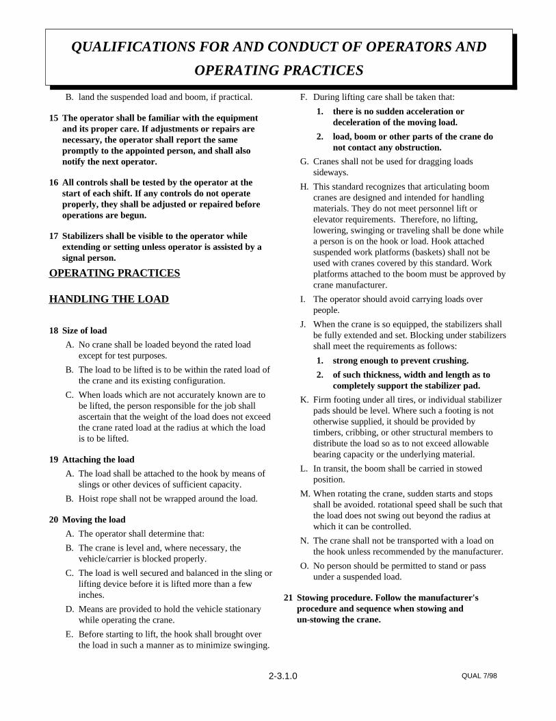
B. land the suspended load and boom, if practical.
15 The operator shall be familiar with the equipmentand its proper care. If adjustments or repairs arenecessary, the operator shall report the samepromptly to the appointed person, and shall alsonotify the next operator.
16 All controls shall be tested by the operator at thestart of each shift. If any controls do not operateproperly, they shall be adjusted or repaired beforeoperations are begun.
17 Stabilizers shall be visible to the operator whileextending or setting unless operator is assisted by asignal person.
OPERATING PRACTICES
HANDLING THE LOAD
18 Size of load
A. No crane shall be loaded beyond the rated loadexcept for test purposes.
B. The load to be lifted is to be within the rated load ofthe crane and its existing configuration.
C. When loads which are not accurately known are tobe lifted, the person responsible for the job shallascertain that the weight of the load does not exceedthe crane rated load at the radius at which the loadis to be lifted.
19 Attaching the load
A. The load shall be attached to the hook by means ofslings or other devices of sufficient capacity.
B. Hoist rope shall not be wrapped around the load.
20 Moving the load
A. The operator shall determine that:
B. The crane is level and, where necessary, thevehicle/carrier is blocked properly.
C. The load is well secured and balanced in the sling orlifting device before it is lifted more than a fewinches.
D. Means are provided to hold the vehicle stationarywhile operating the crane.
E. Before starting to lift, the hook shall brought overthe load in such a manner as to minimize swinging.
F. During lifting care shall be taken that:
1. there is no sudden acceleration ordeceleration of the moving load.
2. load, boom or other parts of the crane donot contact any obstruction.
G. Cranes shall not be used for dragging loadssideways.
H. This standard recognizes that articulating boomcranes are designed and intended for handlingmaterials. They do not meet personnel lift orelevator requirements. Therefore, no lifting,lowering, swinging or traveling shall be done whilea person is on the hook or load. Hook attachedsuspended work platforms (baskets) shall not beused with cranes covered by this standard. Workplatforms attached to the boom must be approved bycrane manufacturer.
I. The operator should avoid carrying loads overpeople.
J. When the crane is so equipped, the stabilizers shallbe fully extended and set. Blocking under stabilizersshall meet the requirements as follows:
1. strong enough to prevent crushing.
2. of such thickness, width and length as tocompletely support the stabilizer pad.
K. Firm footing under all tires, or individual stabilizerpads should be level. Where such a footing is nototherwise supplied, it should be provided bytimbers, cribbing, or other structural members todistribute the load so as to not exceed allowablebearing capacity or the underlying material.
L. In transit, the boom shall be carried in stowedposition.
M. When rotating the crane, sudden starts and stopsshall be avoided. rotational speed shall be such thatthe load does not swing out beyond the radius atwhich it can be controlled.
N. The crane shall not be transported with a load onthe hook unless recommended by the manufacturer.
O. No person should be permitted to stand or passunder a suspended load.
21 Stowing procedure. Follow the manufacturer'sprocedure and sequence when stowing andun-stowing the crane.
QUALIFICATIONS FOR AND CONDUCT OF OPERATORS AND
OPERATING PRACTICES
QUAL 7/982-3.1.0

MISCELLANEOUS
OPERATING NEAR ELECTRICAL POWERLINES
22 Cranes shall be operated so that no part of the craneor load enters into the danger zone shown above.
EXCEPTIONS
A. The danger zone may be entered after confirmationby an appointed person that the electricaldistribution and transmission lines have beende-energized and visibly grounded at the point ofwork; or
B. The danger zone may be entered if insulatingbarriers (not a part of nor an attachment to thecrane) have been erected to prevent physical contactwith the lines.
23 For lines rated 50 kV or below, minimum clearancebetween the lines and any part of the crane or load(including handling appendages) shall be 10 ft. (3m).For higher voltages, see Table 1.
24 Caution shall be excercised when working nearoverhead lines, because they can move horizontally orvertically due to wind, moving the danger zone to newpositions.
25 In transit with no load and boom lowered theclearance shall be specified in Table 1.
26 A qualified signalperson shall be assigned to observethe clearance and give warning before approachingthe above limits.
A. Any overhead wire shall be considered to be anenergized line unless and until the person owningsuch line or the electrical utility authorities verifythat it is not an energized line.
B. Exceptions to this procedure, if approved by theadministrative or regulatory authority if thealternate procedure provides equivalent protectionand set forth in writing.
C. Durable signs shall be installed at the operator'sstation and on the outside of the crane, warning thatelectrocution or serious bodily injury may occurunless a minimum clearance of 10 ft. (3.0m)between the crane or the load being handled andenergized power lines. Greater clearances arerequired because of higher voltage as stated above.These signs shall be revised but not removed whenlocal jurisdiction requires greater clearances.
QUALIFICATIONS FOR AND CONDUCT OF OPERATORS AND
OPERATING PRACTICES
QUAL 7/982-3.2.0
(6.1)20over 750 to 1000(4.87)16over 345 to 750(3.83)10over 50 to 345(1.83)6over 0.75 to 50(1.22)4over to 0.75
while in transit with no load and boom lowered
(13.72)45over 750 to 1000(10.67)35over 500 to 750(7.62)25over 350 to 500(6.1)20over 200 to 350(4.6)15over 50 to 200(3.05)10over to 50
when operating near high voltage power lines
(m)ft(phase to phase)normal voltage, kV
clearance minimum required
TABLE 1

INSPECTION CLASSIFICATION
27 Initial inspection. Prior to initial use, all new, altered,modified or extensively repaired cranes shall beinspected by a designated person to insure compli-ance with provisions of this standard.
28 Regular inspection. Inspection procedure for cranesin regular service is divided into two general classifi-cations based upon the intervals at which inspectionshould be performed. The intervals in turn aredependent upon the nature of the components of thecrane and the degree of their exposure to wear,deterioration, or malfunction. The two general classi-fications are herein designated as "frequent" and"periodic" with respective intervals between inspec-tions as defined below.
A. frequent inspection - daily to monthly intervals
B. periodic inspection - one to twelve intervals, or asspecifically recommended by the manufacturer
FREQUENT INSPECTION
29 Inspection shall be performed by designatedpersonnel.
A. control mechanisms for maladjustment interferingwith proper operation - daily, when used
B. control mechanisms for excessive wear of compo-nents and contamination by lubricants or otherforeign matter
C. safety devices for malfunction
D. all hydraulic hoses, particularly those which flex innormal operation of crane functions, should bevisually inspected once every working day, whenused
E. hooks and latches for deformation, chemicaldamage, cracks, and wear. Refer to ANSI/ASMEB30.10
F. rope reeving for compliance with crane manufac-turer's specifications, if optional winch is used
G. electrical apparatus for malfunctioning, signs ofexcessive deterioration, dirt and moisture accumula-tion
H. hydraulic system for proper oil level and leaks daily
I. tires for recommended inflation pressure, cuts andloose wheel nuts
J. connecting pins and locking device for wear anddamage
PERIODIC INSPECTION
30 Deformed, cracked or corroded members in thecrane structure and carrier.
31 Loose bolts, particularly mounting bolts.
32 Cracked or worn sheaves and drums.
33 Worn, cracked, or distorted parts such as pins,bearings, shafts, gears, rollers and devices.
34 Excessive wear on brake and clutch system parts andlining.
35 Crane hooks inspected for cracks.
36 Travel steering, braking, and locking devices, formalfunction.
37 Excessively worn or damaged tires.
38 Hydraulic and pneumatic hose, fittings, and tubinginspection.
A. evidence of leakage at the surface of the flexiblehose or its junction with metal and coupling
B. blistering, or abnormal deformation to the outercovering of the hydraulic or pneumatic hose
C. leakage at threaded or clamped joints that cannot beeliminated by normal tightening or recommendedprocedures
D. evidence or excessive abrasion or scrubbing on theouter surface of a hose, rigid tube, or fitting. Meansshall be taken to eliminate the interference of
INSPECTION, TESTING AND MAINTENANCE
GENERAL
INSP 9/981-3.1.0

elements in contact or otherwise protect thecomponents
39 Hydraulic and pneumatic pumps and motorsinspection.
A. loose bolts or fasteners
B. leaks at joints between sections
C. shaft seal leaks
D. unusual noises or vibrations
E. loss of operating speed
F. excessive heating of the fluid
G. loss of pressure
40 Hydraulic and pneumatic valves inspection.
A. cracks in valve housing
B. improper return of spool to neutral position
C. leaks at spools or joints
D. sticking spools
E. failure of relief valves to attain or maintain correctpressure setting
F. relief valve pressure shall be checked as specified bythe manufacturers
41 Hydraulic and pneumatic cylinders inspection.
A. drifting caused by fluid leaking across piston
B. rod seals leaking
C. leaks at welding joints
D. scored, nicked, or dented cylinder rods
E. damaged case (barrel)
F. loose or deformed rod eyes or connecting joints
42 Hydraulic filters. Evidence of rubber particles on thefilter elements may indicate hose, "O" ring, or otherrubber component deterioration. Metal chips orpieces on the filter may denote failure in pumps,motors, or cylinders. Further checking will be
necessary to determine origin of the problem beforecorrective action can be taken.
43 Labels are to be in place and legible.
CRANES NOT IN REGULAR USE
44 A crane which has been idle for a period of over onemonth or more, but not less than six months, shall begiven an inspection conforming with the initial-regular- frequent inspections.
45 A crane which has been idle for a period of over sixmonths shall be given a complete inspection conform-ing with the initial-regular-frequent inspectionrequirements.
INSPECTION RECORDS
46 Dated records for periodic inspection should be madeon critical items such as brakes, crane hooks, rope,hydraulic and pneumatic cylinders, and hydraulicand pneumatic relief pressure valves. Records shouldbe kept available to an appointed person.
OPERATIONAL TESTS
47 Prior to initial use, all new, altered, modified, orextensively repaired cranes shall be tested for compli-ance with the operational requirements of thissection, including functions such as the following:
A. load lifting and lowering mechanisms
B. boom lifting and lowering mechanisms
C. boom extension and retraction mechanisms
D. swing mechanisms
E. safety devices
F. operating controls comply with appropriate functionlabels
Operational crane test results shall be madeavailable to an appointed person.
RATED TEST LOADPrior to initial use, altered, modified, orextensively repaired cranes shall be load
INSPECTION, TESTING AND MAINTENANCE
GENERAL
INSP 9/981-3.2.0

tested by or under the direction of anappointed person.
48 Test loads shall not exceed 110% of the manufac-turer's load ratings.
49 Written reports shall be maintained showing testprocedures and confirming the adequacy of repairs.
MAINTENANCE
PREVENTIVE MAINTENANCE
50 Before adjustment and repairs are started on a crane,the following precautions shall be taken asapplicable:
A. crane placed where it will cause the least interfer-ence with other equipment or operations
B. all controls at the "off" position
C. starting means rendered inoperative
D. boom lowered to the ground if possible or otherwisesecured against dropping
E. relieve hydraulic oil pressure from all hydrauliccircuits before loosening or removing hydrauliccomponents
51 Warning or "OUT OF ORDER" signs shall be placedon the crane controls.
52 After adjustments and repairs have been made, thecrane shall not be returned to service until all guardshave been reinstalled, trapped air removed fromhydraulic system (if required), safety devices reacti-vated, and maintenance equipment removed.
ADJUSTMENTS AND REPAIRS
53 Any hazardous conditions disclosed by the inspectionrequirements shall be corrected before operation ofcrane is resumed, Adjustments and repairs shall bedone only by designated personnel.
54 Adjustments shall be maintained to assure correctfunctioning of components, The following areexamples:
A. functional operating mechanism
B. safety devices
C. control systems
55 Repairs or replacements shall be provided as neededfor operation.
The following are examples:
A. critical parts of functional operating mechanismswhich are cracked, broken, corroded, bent, or exces-sively worn
B. critical parts of the crane structure which arecracked, bent, broken, or excessively corroded
C. crane hooks showing cracks, damage, or corrosionshall be taken out of service. Repairs by welding arenot recommended
56 Instructions shall be provided by the manufacturerfor the removal of air from hydraulic circuits.
LUBRICATIONAll moving parts of the crane, for whichlubrication is specified, should be regularlylubricated per the manufacturer'srecommendations and procedures.
ROPE INSPECTION
57 Frequent Inspection
A. All running ropes in service should be visuallyinspected once each working day. A visual inspec-tion shall consist of observation of all rope whichcan be in use during the days operations. Thesevisual observations should be considered withdiscovering gross damage such as listed below,which may be an immediate hazard.
1. distortion of the rope such as kinking,crushing, un-stranding, birdcaging, mainstrand displacement, or core protrusion.Loss of rope diameter in a short length orunevenness of outer strands should bereplaced
2. general corrosion
INSPECTION, TESTING AND MAINTENANCE
GENERAL
INSP 9/981-3.3.0

3. broken or cut strands;
4. number, distribution and type of visiblebroken wires. When such damage isdiscovered, the rope shall either beremoved from service or given asinspection.
B. Care shall be taken when inspecting sections ofrapid deterioration such as flange points, crossoverpoints, and repetitive pickup points on drums.
58 Periodic inspection
A. The inspection frequency shall be determined by aqualified person and shall be based on such factorsas:
1. expected rope life as determined byexperience on the particular installation orsimilar installations
2. severity of environment
3. percentage of capacity lifts
4. frequency rates of operation
5. exposure to shock loads
Inspection need not be at equal calendarintervals and should be more frequent as therope approaches the end of it's service life.This inspection shall be made at leastannually.
B. Periodic inspection shall be performed by a desig-nated person. This inspection shall cover the entirelength of the rope. Only the surface wires need beinspected. No attempt should be made to open therope. Any deterioration results in appreciable loss oforiginal strength, such as described below, shall benoted and determination made as to whether use ofthe rope would constitute a hazard: points listedabove reduction of rope diameter below nominaldiameter due to loss of core support, internal orexternal corrosion, or wear of outside wires;severely corroded, cracked, bent, worn or improp-erly applied connections;
C. Care shall be taken when inspecting sections subjectto rapid deterioration such as the following:
1. sections in contact with saddles, equalizersheaves, or other sheaves where rope travelis limited
2. sections of the rope at or near terminal endswhere corroded or broken wires mayprotrude
ROPE REPLACEMENT
59 No precise rules can be given for determination of theexact time for replacement of rope, since manyvariable factors are involved.
Continued use in this respect depends upongood judgement by a designated person inevaluating remaining strength in a used ropeafter allowance for deterioration disclosed byinspection. Continued rope operation dependsupon this remaining strength.
60 Conditions such as the following shall be reason forquestioning continued use of the rope or increasingthe frequency of inspection:
A. in running ropes, six randomly distributed brokenwires in one lay or three broken wires in one strandin one lay
B. one outer wire broken at the contact point with thecore of the rope structure and protrudes or loops outof the rope structure. Additional inspection of thissection is required
C. wear of one third of the original diameter of theoutside individual wire
D. kinking, crushing, birdcaging, or any other damageresulting in distortion of the rope structure
E. evidence of any heat damage from any cause
F. reduction from nominal diameter of more than 1/64in. (0.4mm) for diameters up to and including 5/16in. (8 mm), 1/32 in. (0.8 mm) for diameter 3/8 in.(9.5 mm) to and including 1/2 in. (13 mm), 3/64 in.(1.2 mm) for diameter 9/16 in. (14.5 mm) to andincluding 3/4 in. (19 mm). 1/16 in. (1.6 mm) fordiameter 7/8 in. (22 mm) to and including 11/8 in.(29 mm), 3/32 in. (2.4 mm) for diameters 11/4 in.(32 mm) to and including 11/2 in. (38 mm)
INSPECTION, TESTING AND MAINTENANCE
GENERAL
INSP 9/981-3.4.0

G. In standing ropes, more than two broken wires inone lay in sections beyond end connections or morethan one broken wire at an end connection.
H. Replacement rope shall have a strength rating atleast as great as the original rope furnished orrecommended by the crane manufacturer. Anydeviation from the original size, grade, or construc-tion shall be specified by a rope manufacturer, or aqualified person.
61 Rope not in regular use: all rope which has been idlefor a period of a month or more due to shutdown orstorage of a crane on which it is installed, shall begiven and inspection in accordance with above infor-mation before it is placed in service. This inspectionshall be for all types of deterioration and shall beperformed by a qualified person.
62 Inspection records
A. frequent inspection- no records required
B. periodic inspections- in order to establish data as abasis for judging the proper time for replacement, adated report condition at each periodic inspectionshould be kept on file. This report shall cover points of deterioration listed above.
ROPE MAINTENANCE
63 Rope should be stored to prevent damage ordeterioration.
64 Unreeling or uncoiling of rope shall be done asrecommended by the rope manufacturer and withcare to avoid kinking or inducing twist.
65 Before cutting a rope, seizing shall be placed on eachside of the place where the rope is to be cut to preventunlaying of the strands. On pre-formed rope, oneseizing on each side of the cut is required. Onnon-preformed ropes of 7/8 in. (22 mm) diameter orsmaller, two seizings on each side of the cut arerequired, and for non-preformed rope 1 in. (25 mm)diameter or larger, three seizings on each side of thecut are required.
66 During installation care should be exercised to avoiddragging of the rope in the dirt or around objectswhich will scrape, nick crush or induce sharp bendsin it.
67 Rope should be maintained in a well-lubricatedcondition. It is important that lubricant applied as apart of a maintenance program shall be compatiblewith the original lubricant and to this end the ropemanufacturer should be consulted. Lubricant appliedshall be the type which does not hinder visual inspec-tion. Those sections of rope which are located oversheaves or otherwise hidden during inspection andmaintenance procedures require special attentionwhen lubricating rope. The object of rope lubricationis to reduce internal friction and to prevent corrosion.
68 When an operating rope shows greater wear or welldefined localized areas than on the remainder of therope, rope life can be extended in cases where asection at the worn end, and thus shifting the wear todifferent areas of the rope.
INSPECTION, TESTING AND MAINTENANCE
GENERAL
INSP 9/981-3.5.0

Maintenance of Auto Crane unit batteries differs verylittle from the generally prescribed maintenance of anylead acid battery. All batteries must be kept properlycharged, properly filled with water, and relativelyclean.
Keep Properly Charged
Many things affect the proper charge to a battery, suchas:
1 Regulator settings
2 Proper tightness of belts on the alternator or generator
3 Good, clean connections of all cablesand wires at the following places:A. BatteryB. RegulatorC. Starting motorD. Alternator or generatorE. Ground connections (most important)
It is of extreme importance to keep the battery as fullycharged as possible without overcharging, especiallywhen vehicles are left outside for extended periods inextremely cold climates. A battery can freeze.Freezing points for various specific gravities of acid areas follows:
Specific Gravity Freezing Temp.(Corrected to 80ºF) Degrees F.
1.280 -90ºF 1.250 -62ºF 1.200 -16ºF 1.150 5ºF 1.100 19ºF
As shown, a half-charged battery (about 1.200 specificgravity) cannot stand for any length of time at 20ºF or itwill freeze. The main reason for keeping the battery as fullycharged as possible without over-charging is to ensurethat power is available even though the vehicle has beenstanding for some time.
Keep Properly Filled with Water
The battery should always be properly filled with water.If the electrolyte level is allowed to fall below the top ofthe plates, the results become threefold:
1 The exposed portion of the plate will becomesulfated.
2 The portion of the plate exposed is not usable.
3 That portion of the acid remaining becomes moreconcentrated and may cause more rapiddeterioration of the remaining parts of the battery.
Keep A Relatively Clean Battery
The battery should be kept clean. Batteries filled withacid and which are not in use self-discharge to a limiteddegree because of the nature of the materials within thebattery. If dirt is allowed to collect on the top of thebattery (and this dirt absorbs moisture) and electricalpath can be set up between the various terminals of thebattery and the ground. Once such a path has beenestablished, the self-discharge of the battery isaccelerated. This also accelerates corrosion of thebattery cables at the terminals.
Periodic Maintenance is Needed
A definite program of periodic maintenance of allbatteries should be conducted on a regular basis.Periodic maintenance includes:
1 Checking belts for tightness on the chargingequipment
2 Checking battery electrolyte levels
3 Checking cables for good connections
4 Cleaning where corrosion is apparent
When corrosion is cleaned off, the cable terminals andbattery terminals should be coated with a light coatingof petroleum jelly before they are replaced. Whenterminals are cleaned, the top of the battery should becleaned with a mild solution of soda water.
MAINTBAT 9/98
MAINTENANCE OF BATTERIES
1-6.1.0.
Low Maintenance Batteries(Maintenance Free)
Low maintenance batteries should not be used onAuto Cranes or trucks equipped with Auto Cranes.The batteries are not designed for "deep" discharge.
Testing Your Battery
If the condition of the battery is in question, it should beremoved from the vehicle, taken to the shop, andallowed to reach room temperature. It should then berecharged until specific gravity readings taken atone-half hour intervals. If the specific gravity readingsare fairly uniform, the battery should be checked with ahigh rate tester. Use the tester in accordance with themanufacturer's instructions. The high rate tester is thebest method to test a questionable battery.
If, after charging, it is noted that the specific gravityreading of one cell is 30 points less than any of theother cells, it may be assumed that the cell is bad andthat the battery should be replaced. If all cells areuniform but not up to full charge, a low rate of charge
should be attempted for an extended time. This usuallywill recover a badly sulfated battery.
Replacing a Battery
If it is necessary to replace a battery, and a dry chargebattery is used, the following procedure applies:
1 Fill the battery with electrolyte of the properspecific gravity.
2 Place the battery on charge according to themanufacturer's instructions.
It is essential that the second step above be followed toensure that the battery going on the vehicle is fullycharged.
It is also very important that the battery hold-downs bechecked periodically to ensure that the batteries areproperly positioned to avoid vibration problems,breakage of cables or terminals. Care must be taken toavoid cracking or breaking containers or covers bytightening hold-down fixtures excessively. They alsomust not be so loose that breakage results from ahold-down that is too loose.
MAINTBAT 9/98
MAINTENANCE OF BATTERIES
1-6.2.0.

So many variable factors can cause the deterioration of wire line cable that it is notpossible to determine a definite life expectancy. Some of these factors are:
• Load being handled.
• Corrosive conditions.
• Maintenance of the unit: Keep the sheaves turning freely. Maintain tension on cable to insure proper spooling. Avoid kinks in cable. Avoid abrasive action and contact with sharp corner.
• Frequency of use.
Auto Crane units, up to 2,400 pound ratings use 3/16 inch diameter galvanizedpre-formed 7 x 19 aircraft cable. This cable has a working strength, when new, of 4,200 pounds.It is recommended when 1,200 pound loads are exceeded to use a two part line with a travelingblock. This will ensure a 3.5 to 1 safety factor when the cable is new.
Keeping the above factor of safety in mind and knowing the kind of loads that will behandled, the user can determine by inspection of the cable as to when it should be replaced.
Items to look for while inspecting the cables are:
• Broken strands.• Kinks and flattened sections.• Corrosion and abrasion.
Lubrication of the wire line serves two important purposes: • Prevent corrosion. • Reduce wear due to flexing and abrasion caused by contact with the sheaves, rollers, and
cable on the drum.
PreparationRemove rust and foreign matter with a wire brush and wipe clean. Be sure cable is dry.
ApplicationMethod 1: Dip a brush into a light weight motor oil and apply. In some cases, dip a rag or a piece
of sheepskin into the lubricant and swab the lubricant on to the rope.Method 2: Apply a heavier lubricant such as a grease gun lubricant with hands while wearing
leather gloves. (Leather gloves give greater protection and less penetration of the grease thancanvas gloves.)
7-1.0.0 WIRE 1/2000
LIFE OF WIRE LINE
WIRE LINE LUBRICATION

SEALED BEARING-NO MAINTENANCE REQUIREDROTATION BEARINGS
DRAIN, FLUSH, & REFILL WITH MOBIL DTE 13, OR EQUIVALENT
XHYDRAULIC FLUID
WORM GEAR-EP GEAR LUBE SAE 80-90,SPUR GEAR SAE 30 OIL
XHOIST GEARBOX
GREASE WITH MOBILPLEX EP-2 OR EQUIVALENT @ ZERKS
XROTATION WORMBEARINGS (MR) (PR)
WATER PROOF BEARING GREASE OR DRYMOLYLUBE IF DUSTY CONDITIONS
XROTATION GEAR(MR) (PR)
CHECK INSULATION FOR DAMAGE ORDETERIORATION
XPOWER CABLE
INSPECT AND REPLACE AS NEEDEDXSAFETY DECALS
CHECK ADJUSTMENTXROTATION BRAKE (M)
CHECK FOR CORROSION & TIGHT CONNEC-TIONS. CLEAN & COAT AS REQUIRED
XBATTERY CONNECTIONS
GREASE WITH MOBILPLEX EP-2 OR EQUIVALENT @ ZERKS
XBOOM CYLINDERPINS
CHECK AROUND CYLINDER ROD FOREXCESS FLUID LEAKAGE
XBOOM CYLINDER
CHECK-TIGHTEN AS REQUIREDXALL OTHER BOLTS
SEALED BEARING, REPLACE IF ROUGH ORLOOSE
XSHEAVE BEARINGS
CHECK TERMINALS FOR TIGHTCONNECTIONS
XMOTORCONNECTION
CHECK-TORQUE TO 85 FT-LBS (DRY) ASREQUIRED
XMOUNTING BOLTS
CHECK FOR FLATTENING, KINKS, &BROKEN STRANDS, SEE MANUAL
XHOIST CABLE
MAKE SURE CABLE IS WOUND EVENLY ONDRUM
XCABLE DRUM
INSPECT HOOK & LATCH FOR DEFORMA-TION, CRACKS, & CORROSION
XLOAD HOOK
NOTESYEAR6 MOSMONTHWEEKDAYSERVICE PERFORMED
LUBRICATION & MAINTENANCESCHEDULE 2703 CRANE
2703MAIN 6/991-7.0.0
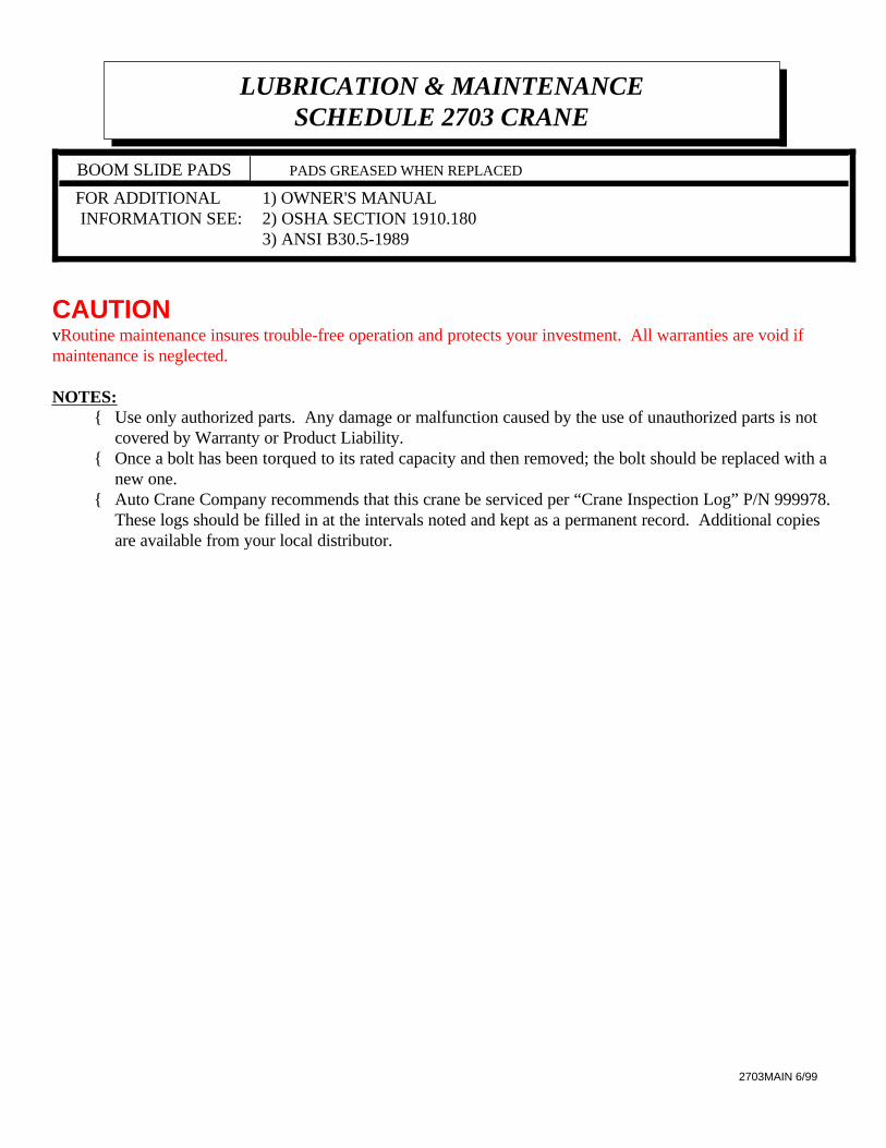
1) OWNER'S MANUAL 2) OSHA SECTION 1910.180 3) ANSI B30.5-1989
FOR ADDITIONAL INFORMATION SEE:
PADS GREASED WHEN REPLACED BOOM SLIDE PADS
CAUTIONvRoutine maintenance insures trouble-free operation and protects your investment. All warranties are void ifmaintenance is neglected.
NOTES:{ Use only authorized parts. Any damage or malfunction caused by the use of unauthorized parts is not
covered by Warranty or Product Liability.{ Once a bolt has been torqued to its rated capacity and then removed; the bolt should be replaced with a
new one.{ Auto Crane Company recommends that this crane be serviced per “Crane Inspection Log” P/N 999978.
These logs should be filled in at the intervals noted and kept as a permanent record. Additional copiesare available from your local distributor.
LUBRICATION & MAINTENANCESCHEDULE 2703 CRANE
2703MAIN 6/99

NOTE: For mounting bolt hole pattern - see page 5-1.0.0.
INSTALLATION - BATTERY CABLE
1. Drill 13/16" hole in floor. Install bushing, which is connected to cable, so it fits hole snug.
2. Run cable to positive battery terminal. Connect black cable to negative battery terminal orsuitable chassis ground point. Locate cables so that they will be protected. Avoid sharpedges. Use the No. 083800 frame clips provided to hold cables securely in place.
3. If the battery is grounded to the engine it may be necessary to add an additional groundcable from the engine to the chassis frame to obtain maximum power at crane
AW053 4/98
ASSEMBLY & INSTALLATION INSTRUCTIONS
2703 SERIES
2-1.0.0

WARNING:As with all Auto Crane power rotation units, the 2703 does require a boom support.
Suggested Boom Support:Auto Crane P/N 725045
BOOM SUPPORT
2703 SERIES
AW058 4/982-2.2.0

GENERAL ASSEMBLY
P/N 270300 - 2703 M, 6-10-14 BOOM
AW270300 8/983-1.0.0

GENERAL ASSEMBLY
P/N 270300 - 2703 M, 6-10-14 BOOM
AW270300 8/98
NUT HEX 1-12 NF019106 138
SCREW HEX HD 1-12 NF x 5 1/2 GR5330185 137
NUT HEX HALF-LOCK 5/8-18 NF018100 136
SCREW HEX HD 5/8-18 NF x 1 3/4 GR5012200 135
RETAINER MANUAL BOOM320415 134
WASHER SP LK 1/4020200 733
SCREW HEX HD 1/4-28 NC x 3/4 005501 132
SCREW HEX HD 5/16-18 x 5/8 SELF-TAP002614 131
75’ OPTIONAL CABLE ASSEMBLY320339 130
62’ STANDARD CABLE ASSEMBLY320338 129
TRAVELING BLOCK320433 128
LONG POSITION PIN320328 127
POSITION PIN370002 126
SHEAVE ASSEMBLY (BEARING ONLY 200100)227401 125
SPACER 340303 224
GRIP HANDLE270325-007 123
PUMP HANDLE270325-006 122
BEARING FLANGE330470 121
RELAY ASSEMBLY270404 120
PENDANT CONTROL330519 119
REAR PANEL270391 118
ACTUATOR BRACKET270403 117
ACTUATOR ASSEMBLY320324 116
CABLE GUARD270389115
COLLAR SP LK330468 214
DRUM320379 113
REPAIR KIT (FOR 270325 CYL)270325-002 112
SEAL KIT (FOR 270325 CYL)270325-001 111
HYDRAULIC CYLINDER270325 110
MANUAL BOOM w/ CROWN320423 19
MID BOOM270408 18
LOWER WELDMENT BOOM270380 17
LEFT PIVOT BOOM330471-001 16
RIGHT PIVOT BOOM330471 15
SNAP RING330182 14
SEALED BALL BEARING330192 23
QUILL HOUSING WELDMENT270419 12
QUILL / BASE27043211
DESCRIPTIONP/NQTYITEM
3-1.1.0

GENERAL ASSEMBLY
P/N 270300 - 2703 M, 6-10-14 BOOM
AW270300 8/98
WASHER SP LK 1/2021500 455
NUT HEX 1/2-20 NF HEAVY017704 454
SCREW HEX HD 1/2-20 NF x 2 1/2 GR5011200 453
NUT HEX LOCK 3/4-16 NF018600 152
SCREW HEX HD 3/4-16 NC x 5 GR5014400 151
SCREW HEX HD 3/8-16 NC x 1 GR8330371 650
WASHER SP LK 3/8021100 1949
NUT HEX 3/8-16 NF330372 1948
SCREW HEX HD 3/8-16 NC x 7/8330370 1247
RECEPTACLE ASSEMBLY (see RELAY ASSEMBLY)REF 146
SCREW HEX HD 3/8 NC x 1/2008401 145
WASHER SP LK 5/16020600 444
SCREW HEX HD 5/16-18 NC x 3/4007807 443
NUT HEX 1/4-20 NC015900 542
SCREW HEX HD 1/4 NC x 3/4 005500 541
NUT HEX LOCK 1/4-20 NC016300 140
ANGLE INDICATOR360038 139
DESCRIPTIONP/NQTYITEM
3-1.2.0

AW270302 8/98
GENERAL ASSEMBLY
P/N 270302 - 2703 MR, 6-10-14 BOOM
3-2.0.0

AW270302 8/98
GENERAL ASSEMBLY
P/N 270302 - 2703 MR, 6-10-14 BOOM
SCREW HEX HD 5/8-18 NF x 1 3/4 GR5012200 138
WASHER SP LK 1/4020200 337
SCREW HEX HD 1/4-28 NF x 3/4005501 136
SCREW HEX HD 5/16-18 NF x 5/8 SELF-TAP002614 135
TRAVELING BLOCK320433 134
POSITION PIN (LONG)320328 133
PIN ASSEMBLY w/ LANYARD370002 132
75’ OPTIONAL CABLE ASSEMBLY320339 131
62’ STANDARD CABLE ASSEMBLY320338 130
SHEAVE ASSEMBLY (BEARING ONLY 200100)227401 129
MANUAL BOOM w/ CROWN320423 128
RETAINER MANUAL BOOM320415 127
MID MANUAL BOOM270408 126
SPACER340303 225
HANDLE GRIP270325-007 124
PUMP HANDLE270325-006 123
REPAIR KIT (FOR 270325 CYLINDER)270325-002 122
SEAL KIT (FOR 270325 CYLINDER)270325-001 121
HYDRAULIC CYLINDER270325 120
BEARING FLANGE330470 119
RELAY ASSEMBLY (see page 6-5.0.0)680052 118
PENDANT CONTROL (see page 6-2.0.0)680068 117
RECEPTACLE ASSEMBLY (see RELAY ASSEMBLY)REF 116
REAR PANEL270391115
12V MOTOR GEAR330313114
ACTUATOR BRACKET270403 113
ACTUATOR ASSEMBLY (see page 3-8.0.0)320324 112
COLLAR SP LK330468 211
CABLE GUARD270389110
DRUM320379 19
LOWER WELDMENT BOOM270380 18
LEFT PIVOT BOOM330471-001 17
RIGHT PIVOT BOOM33047116
WORM GEAR270385 15
SNAP RING330182 14
SEALED BALL BEARING330192 23
QUILL HOUSING WELDMENT270419 12
QUILL / BASE270432 11
DESCRIPTIONP/NQTYITEM
3-2.1.0
AW270302 8/98
GENERAL ASSEMBLY
P/N 270302 - 2703 MR, 6-10-14 BOOM
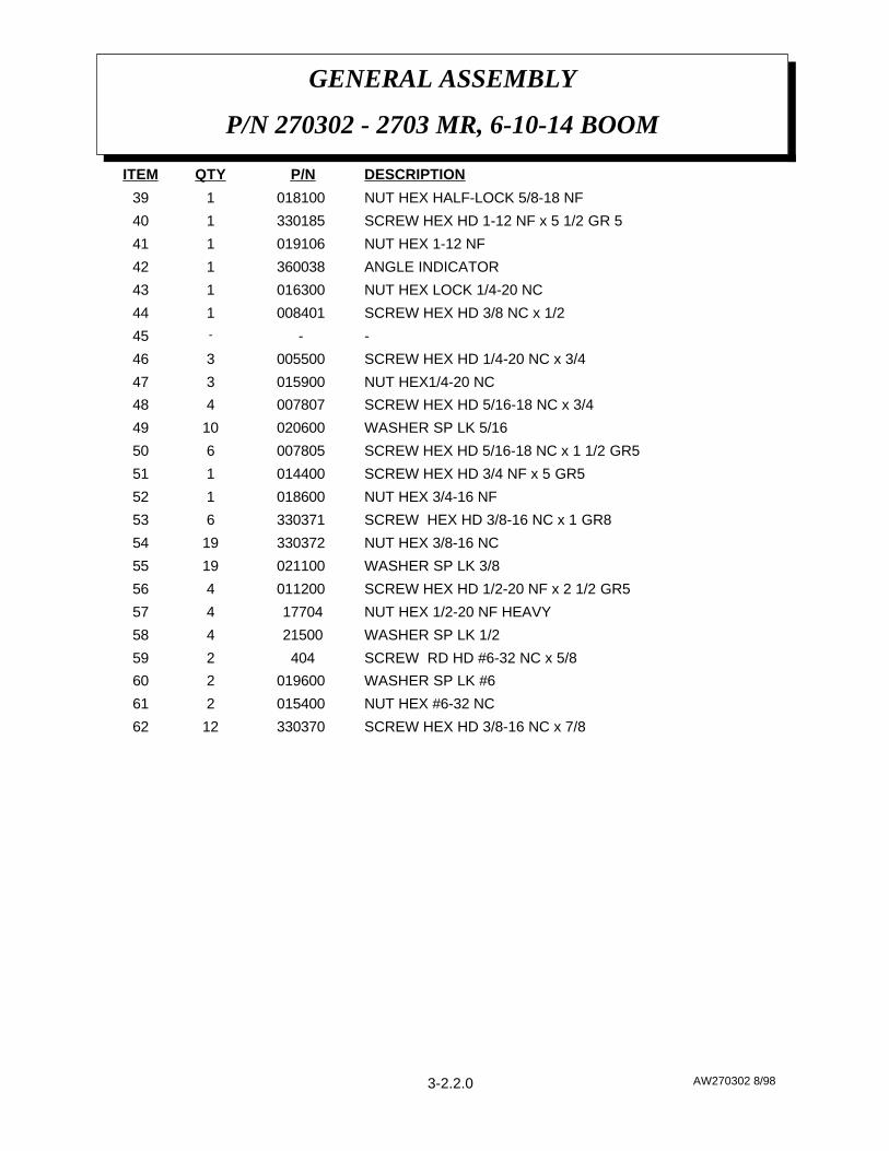
SCREW HEX HD 3/8-16 NC x 7/8330370 1262
NUT HEX #6-32 NC015400 261
WASHER SP LK #6019600 260
SCREW RD HD #6-32 NC x 5/8404259
WASHER SP LK 1/221500458
NUT HEX 1/2-20 NF HEAVY17704457
SCREW HEX HD 1/2-20 NF x 2 1/2 GR5011200 456
WASHER SP LK 3/8021100 1955
NUT HEX 3/8-16 NC330372 1954
SCREW HEX HD 3/8-16 NC x 1 GR8330371 653
NUT HEX 3/4-16 NF018600 152
SCREW HEX HD 3/4 NF x 5 GR5014400 151
SCREW HEX HD 5/16-18 NC x 1 1/2 GR5007805 650
WASHER SP LK 5/16020600 1049
SCREW HEX HD 5/16-18 NC x 3/4007807 448
NUT HEX1/4-20 NC015900 347
SCREW HEX HD 1/4-20 NC x 3/4005500 346
-- -45
SCREW HEX HD 3/8 NC x 1/2008401 144
NUT HEX LOCK 1/4-20 NC016300 143
ANGLE INDICATOR360038 142
NUT HEX 1-12 NF 019106 141
SCREW HEX HD 1-12 NF x 5 1/2 GR 5330185 140
NUT HEX HALF-LOCK 5/8-18 NF018100 139
DESCRIPTIONP/NQTYITEM
3-2.2.0

AW270304 8/98
GENERAL ASSEMBLY
P/N 270304 - 2703 PR, 6-10-14 BOOM
3-2.3.0

AW270304 8/98
GENERAL ASSEMBLY
P/N 270304 - 2703 PR, 6-10-14 BOOM
NUT HEX 1-12 NF019106 138
SCREW HEX HD 1-12 NF x 5 1/2 GR5330185 137
NUT HEX LOCK 5/8-18 NF018100 136
SCREW HEX HD 5/8-18 NF x 1 3/4 GR8012200 135
RETAINER MANUAL BOOM320415 134
LOCK WASHER 1/4020200 1333
SCREW HEX HD 1/4-28 NC x 3/4 005501 132
SCREW HEX HD 5/16-18 x 5/8 SELF-TAP002614 531
75’ OPTIONAL CABLE ASSEMBLY320339 130
62’ STANDARD CABLE ASSEMBLY320338 129
TRAVELING BLOCK (see page 3-7.0.0)320433 128
LONG POSITION PIN320328 127
KEY 1/4 x 1/4 x 2 3/4340523 126
SHEAVE ASSEMBLY (BEARING ONLY 200100)227401 125
SPACER 340303 224
SCREW HEX HD 3/8 NC x 1/2008401 123
PIN ASSEMBLY w/ LANYARD370002 122
BEARING FLANGE330470 121
RELAY ASSEMBLY (see page 6-6.0.0)270416 120
PENDANT CONTROL (see page 6-1.0.0) 270410 119
SCREW HEX HD 3/8 NC x 1 1/4008702 118
ACTUATOR BRACKET270403 117
ACTUATOR ASSEMBLY (see page 3-8.0.0)320324 116
CABLE GUARD270389115
COLLAR 1 1/4 ID330468 214
CABLE DRUM320379 113
REPAIR KIT FOR 270325 CYL (not shown)270325-002 112
SEAL KIT FOR 270325 CYL (not shown)270325-001 111
HYDRAULIC CYLINDER330250 110
MANUAL BOOM w/ CROWN320423 19
MANUAL MID BOOM270408 18
LOWER BOOM WELDMENT 270380 17
LEFT PIVOT BOOM330471-001 16
RIGHT PIVOT BOOM330471 15
SNAP RING330182 14
SEALED BALL BEARING 5.9055 OD330192 23
QUILL HOUSING WELDMENT270419 12
QUILL / BASE270432 11
DESCRIPTIONP/NQTYITEM
3-2.4.0

*BASE MOUNTING HARDWARE TO TRUCK FRAME.
AW270304 8/98
GENERAL ASSEMBLY
P/N 270304 - 2703 PR, 6-10-14 BOOM
O-RING241169165
MANIFOLD SENSE VALVE368985164
NUT HEX 1/2 NF 20 GR 5017704 4*63
SCREW HEX HD 1/2 NF 2 1/2 GR 5011200 4*62
SCREW HEX HD 1/4 NC x 1005604 261
RELAY DROP OUTREF260
SCREW HEX HD 1/4 NC x 2 1/2006700 259
HYDRAULIC PUMP270324158
HOLDING VALVE330412 157
SCREW HEX HD 5/16-18 NC x 1 1/2 GR5007805 656
12V MOTOR GEAR330313155
WORM GEAR270385154
RECEPTACLE ASSEMBLY (see RELAY ASSEMBLY)REF 153
LOCK WASHER021500 4*52
SCREW HEX HD 3/4-16 NC x 1 GR8014400 251
NUT HEX 3/4-16 NF018600 250
SCREW HEX HD 3/8-16 NC x 1 GR8330371949
LOCK WASHER 3/8021100 2548
NUT HEX 3/8-16 NF3303722247
SCREW HEX HD 3/8-16 NC x 7/83303701446
TURNER ASSEMBLY (not shown, see page 3-6.0.0)REF145
LOCK WASHER 5/16020600 1044
SCREW HEX HD 5/16-18 NC x 3/4007807 443
NUT HEX 1/4-20 NC015900 842
SCREW HEX HD 1/4 NC x 3/4 005500 841
NUT HEX LOCK 1/4-20 NC016300 340
ANGLE INDICATOR360038139
DESCRIPTIONP/NQTYITEM
3-2.5.0
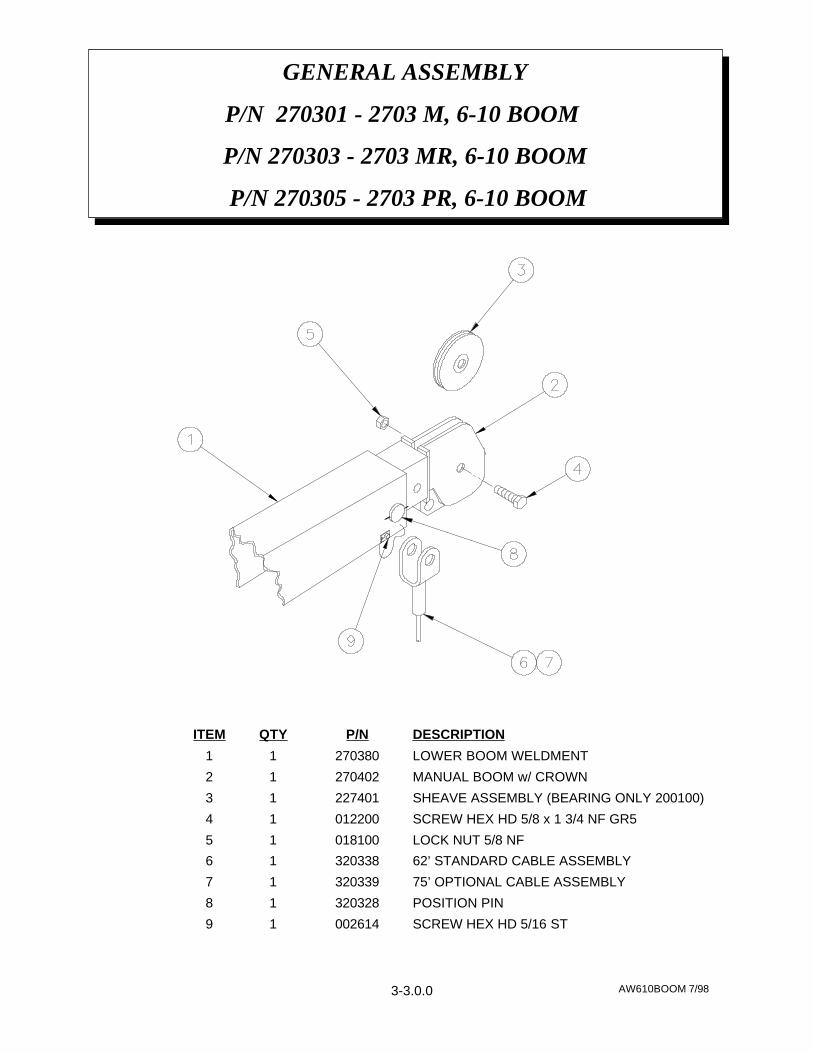
GENERAL ASSEMBLY
P/N 270301 - 2703 M, 6-10 BOOM
P/N 270303 - 2703 MR, 6-10 BOOM
P/N 270305 - 2703 PR, 6-10 BOOM
AW610BOOM 7/983-3.0.0
SCREW HEX HD 5/16 ST00261419
POSITION PIN32032818
75’ OPTIONAL CABLE ASSEMBLY32033917
62’ STANDARD CABLE ASSEMBLY32033816
LOCK NUT 5/8 NF01810015
SCREW HEX HD 5/8 x 1 3/4 NF GR501220014
SHEAVE ASSEMBLY (BEARING ONLY 200100)22740113
MANUAL BOOM w/ CROWN27040212
LOWER BOOM WELDMENT 27038011
DESCRIPTIONP/NQTYITEM

BRAKE ASSEMBLY
2703 M
AW642 4/983-4.0.0
BRAKE HANDLE330136 19
HANDLE GRIP330303 18
SCREW HEX HD 5/8 NC x 7 GR5013503 17
SPACER330489 16
COMPRESSION SPRING330488 15
NUT HEX 5/8 NC018301 14
SPACER33049013
COMPRESSION SPRING33018412
BRAKE BAND ASSEMBLY270376 11
DESCRIPTIONP/NQTYITEM
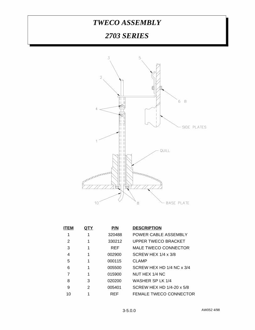
TWECO ASSEMBLY
2703 SERIES
AW052 4/983-5.0.0
FEMALE TWECO CONNECTORREF 110
SCREW HEX HD 1/4-20 x 5/8005401 29
WASHER SP LK 1/4020200 38
NUT HEX 1/4 NC015900 17
SCREW HEX HD 1/4 NC x 3/4005500 16
CLAMP000115 15
SCREW HEX 1/4 x 3/8002900 14
MALE TWECO CONNECTORREF13
UPPER TWECO BRACKET33021212
POWER CABLE ASSEMBLY32048811
DESCRIPTIONP/NQTYITEM
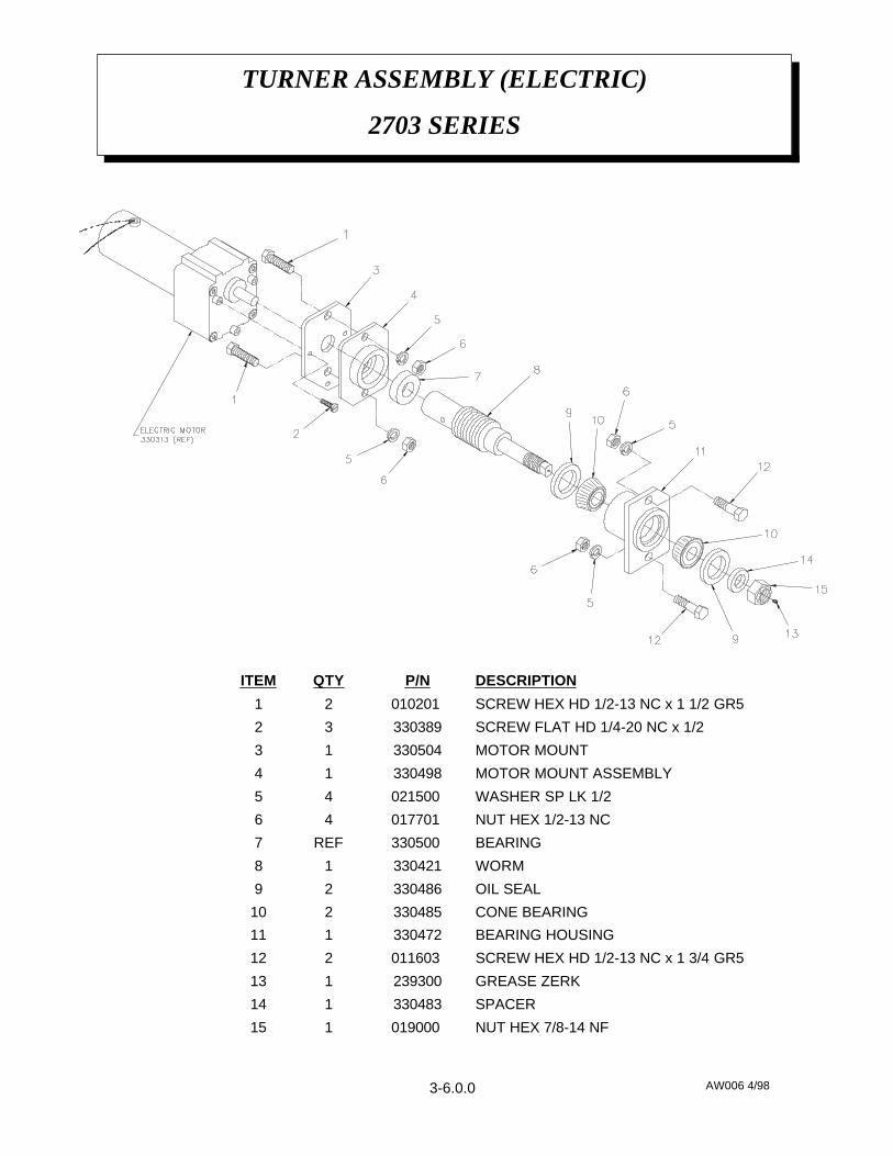
AW006 4/98
TURNER ASSEMBLY (ELECTRIC)
2703 SERIES
3-6.0.0
NUT HEX 7/8-14 NF019000 115
SPACER330483114
GREASE ZERK239300113
SCREW HEX HD 1/2-13 NC x 1 3/4 GR5011603 212
BEARING HOUSING330472111
CONE BEARING330485210
OIL SEAL33048629
WORM33042118
BEARING330500 REF7
NUT HEX 1/2-13 NC017701 46
WASHER SP LK 1/2021500 45
MOTOR MOUNT ASSEMBLY33049814
MOTOR MOUNT33050413
SCREW FLAT HD 1/4-20 NC x 1/233038932
SCREW HEX HD 1/2-13 NC x 1 1/2 GR5010201 21
DESCRIPTIONP/NQTYITEM

NOTE: STANDARD 62’ CABLE ASSEMBLY MAY BE ORDERED USING P/N 320338. OPTIONAL 75’ CABLE ASSEMBLY MAY BE ORDERED USING P/N 320339.
AW320433 9/98
TRAVELING BLOCK ASSEMBLY
P/N 320433
3-7.0.0
FLAT WASHER 330100 29
BLOCK 320404 28
HEX HALF LOCK NUT 5/8 NC01820017
HEX HD SCREW 5/8 NC x 3 1/2 013512 16
SHEAVE ASSEMBLY w/ BEARING 200909 15
TRAVELING BLOCK32040324
BLOCK PIN32043423
HITCH PIN36012422
SWIVEL HOOK 100309 11
DESCRIPTIONP/NQTYITEM

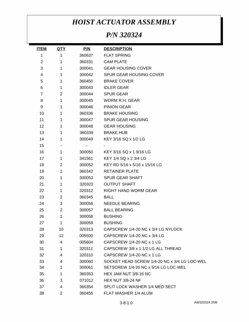
HOIST ACTUATOR ASSEMBLY
P/N 320324
AW320324 2/993-8.0.0
HOIST ACTUATOR ASSEMBLY
P/N 320324
AW320324 2/99
FLAT WASHER 1/4 ALUM360455 238
SPLIT LOCK WASHER 1/4 MED SECT360354 437
HEX NUT 3/8-24 NF071012 336
HEX JAM NUT 3/8-16 NC360353 135
SETSCREW 1/4-20 NC x 5/16 LG LOC-WEL300061 134SOCKET HEAD SCREW 1/4-20 NC x 3/4 LG LOC-WEL300060 433
CAPSCREW 1/4-20 NC x 1 LG320310 432
CAPSCREW 3/8 x 1 1/2 LG ALL THREAD320311 131
CAPSCREW 1/4-20 NC x 1 LG005604 430
CAPSCREW 1/4-20 NC x 3/4 LG005500 1229
CAPSCREW 1/4-20 NC x 3/4 LG NYLOCK320313 1028
BUSHING300059 127
BUSHING300058 126
BALL BEARING300057 225
NEEDLE BEARING 300056 324
BALL360345 223
RIGHT HAND WORM GEAR320312 122
OUTPUT SHAFT320323 121
SPUR GEAR SHAFT300053 120
RETAINER PLATE360342 119
KEY RD 5/16 x 5/16 x 15/16 LG300052 218
KEY 1/4 SQ x 2 3/4 LG341561 117
KEY 3/16 SQ x 1 9/16 LG300050 116
---15
KEY 3/16 SQ x 1/2 LG300049 114
BRAKE HUB360339 113
GEAR HOUSING300048 112
SPUR GEAR HOUSING300047 111
BRAKE HOUSING360336 110
PINION GEAR300046 19
WORM R.H. GEAR300045 18
SPUR GEAR300044 27
IDLER GEAR300043 16
BRAKE COVER360450 15
SPUR GEAR HOUSING COVER300042 14
GEAR HOUSING COVER300041 13
CAM PLATE360331 12
FLAT SPRING360637 11
DESCRIPTIONP/NQTYITEM
3-8.1.0

HOIST ACTUATOR ASSEMBLY
P/N 320324
AW320324 2/99
PIPE PLUG320382 266
SCREW 1/4-20 NC x 1 LG ALL THREAD360456 265
FIBER WASHER300082 164
THRUST WASHER300081 163
THRUST WASHER300080 362
SPRING360368 161
SNAP RING300079 160
THREAD SEAL360371 159
OIL SEAL 1 1/2 ID x 2 1/4 OD x 5/16 THICK300078 158
OIL SEAL 1 1/4 ID x 1 3/4 OD x 1/4 THICK300077 157
OIL SEAL 3/4 ID x 1 1/4 OD x 1/4 THICK300076 156
THRUST PLATE360364 255
DOWEL PIN300075 254
REDUCER -4 NPT / -2 NPT300074 153
PLUG PIPE -6 NPT HEX SOC HEADLESS300073 152
PLUG PIPE -4 NPT SQ HD300070 251
REDUCER -6 NPT / -2 NPT300069 150
O-RING 1 OD x 1/8 THICK300068 149
12V MOTOR300067 148
RELIEF FITTING 300066 247
WOODRUFF KEY300065 146
BRAKE COVER GASKET360359 145
GEAR HOUSING COVER GASKET300064 144
SPUR GEAR HOUSING GASKET300063 143
GASKET BEARING300062 242
90º ELBOW 1/4-18 NPT BOTH ENDS320315 141
90º ELBOW 3/8-18 NPT BOTH ENDS320314 140
SPLIT LOCK WASHER 3/8021100 339
DESCRIPTIONP/NQTYITEM
3-8.2.0

AUTOMATIC SAFETY BRAKE ASSEMBLY
(OIL COOLED) HOIST
AW368 1/99
THRUST PLATE360364 116
GASKET360359 115
WASHER FLAT 1/4 ALUM360455 214
THREAD SEAL360465 413
JAM NUT 3/8 NC360353 112
THREAD SEAL360371 111
CAPSCREW 3/8 NC x 1 1/2 360456 110
COIL SPRING360368 19
CAPSCREW 1/4 NC x 1 360453 68
BRAKE BALL360345 27
RETAINER PLATE360342 16
BRAKE HUB360339 15
BRAKE HOUSING360336 14
HOUSING COVER360450 13
CAM PLATE360331 12
FLAT SPRING360367 11
DESCRIPTIONP/NQTYITEM
3-9.0.0

ASSEMBLY INSTRUCTIONS:1. Winch has right hand worm and gear. Cable spools over drum. Use number
one slots for brake balls(7) in cam plate(2).2. Install brake hub(5) through brake housing(4) on winch worm with key.3. Assemble balls(7) in cam plate(2) using hard grease to hold balls in place.4. Place cam plate(2) on brake hub(5), matching its holes with the balls.5. Install thrust plate(16).6. Thread capscrew(10) with jam nut (12) and thread seal (11) through housing
cover(3).7. Place gasket(15) on housing cover(3).8. Install coil spring(9) on capscrew(10).9. Install flat spring(1) on capscrew(10).
10. Secure retainer plate(6) and flat spring(1) to housing cover(3) usingcapscrews(8) and washers(14).
11. Using capscrews(8) and thead seals(13) attach housing cover(3) to brakehousing(4).
12. Test brake by shifting winch to UP then DOWN to see if brake is working inproper rotation. If not, remove housing cover(3) and locate brake balls(7) inopposite set of slots of cam plate(2).
13. Adjust to suit by tightening or loosening capscrew(10) on outside of housingcover(3). When proper adjustment is obtained, secure capscrew(10) with jamnut(12).
AUTOMATIC SAFETY BRAKE ASSEMBLY
(OIL COOLED) HOIST
AW368 1/993-9.1.0

SAFETY DECAL SECTION
2703DEC 4/98
(see page 4-2.0.0, Item 1)
Both sides of crownPLACEMENT:
2QUANTITY:
To inform the operator of the hazardof proximity or contact with thecrane boom during operation.
FUNCTION:
STAY CLEAR OF BOOMDECAL:
040517PART NO.:
(see page 4-2.0.0,Item 12)
Both sides of downhaul weight
PLACEMENT:
2QUANTITY:
To inform theoperator of thehazard of proximityor contact with thecrane load duringoperation.
FUNCTION:
STAY CLEAR OFLOAD
DECAL:
040518PART NO.:
FIG. SD-1.
(see page 4-2.0.0, Item 15)To inform the operator ofpossible danger at scissors pointon crane.
FUNCTION:
Both sides of lift cylinderPLACEMENT:SCISSORS POINTDECAL:
1QUANTITY: 040519PART NO.:
FIG. SD-3.
FIG. SD-2.
4-1.0.0
SAFETY DECAL SECTION
2703DEC 4/98
FIG. SD-4.
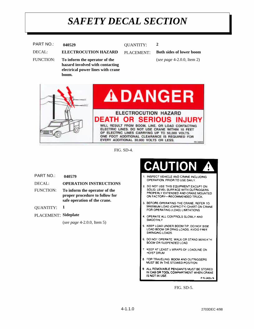
(see page 4-2.0.0, Item 5)
SideplatePLACEMENT:
1QUANTITY:
To inform the operator of theproper procedure to follow forsafe operation of the crane.
FUNCTION:
OPERATION INSTRUCTIONSDECAL:
040579PART NO.:
FIG. SD-5.
4-1.1.0
(see page 4-2.0.0, Item 2)To inform the operator of thehazard involved with contactingelectrical power lines with craneboom.
FUNCTION:
Both sides of lower boomPLACEMENT:ELECTROCUTION HAZARDDECAL:
2QUANTITY: 040529PART NO.:
SAFETY DECAL SECTION
2703DEC 4/98
FIG. SD-7.
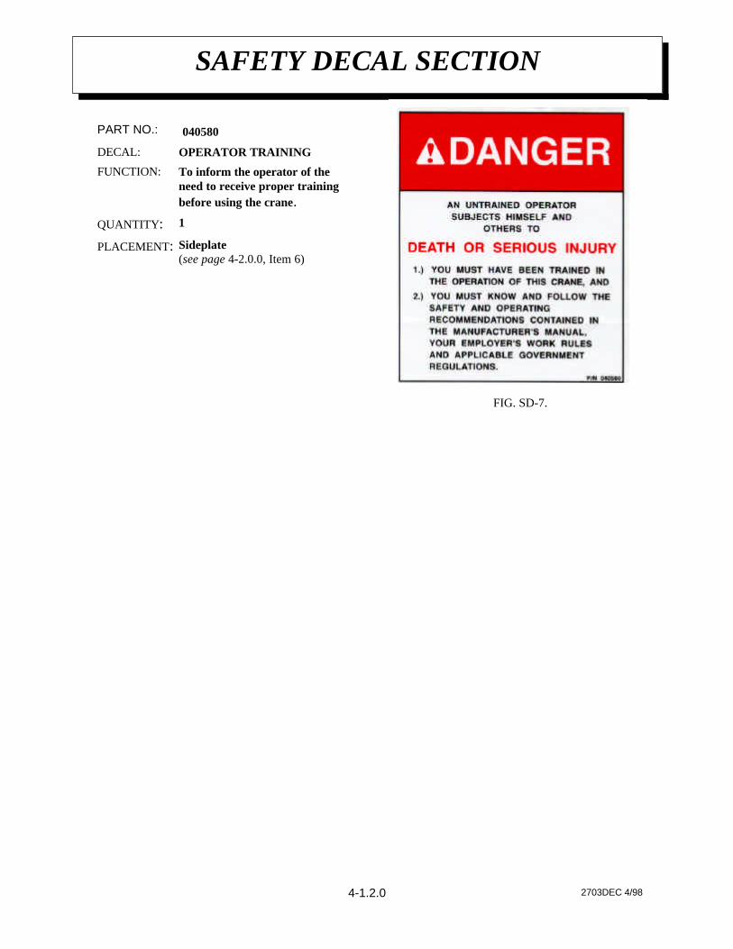
Sideplate(see page 4-2.0.0, Item 6)
PLACEMENT:
1QUANTITY:
To inform the operator of theneed to receive proper trainingbefore using the crane.
FUNCTION:
OPERATOR TRAININGDECAL:
040580PART NO.:
4-1.2.0
AW270395 4/98
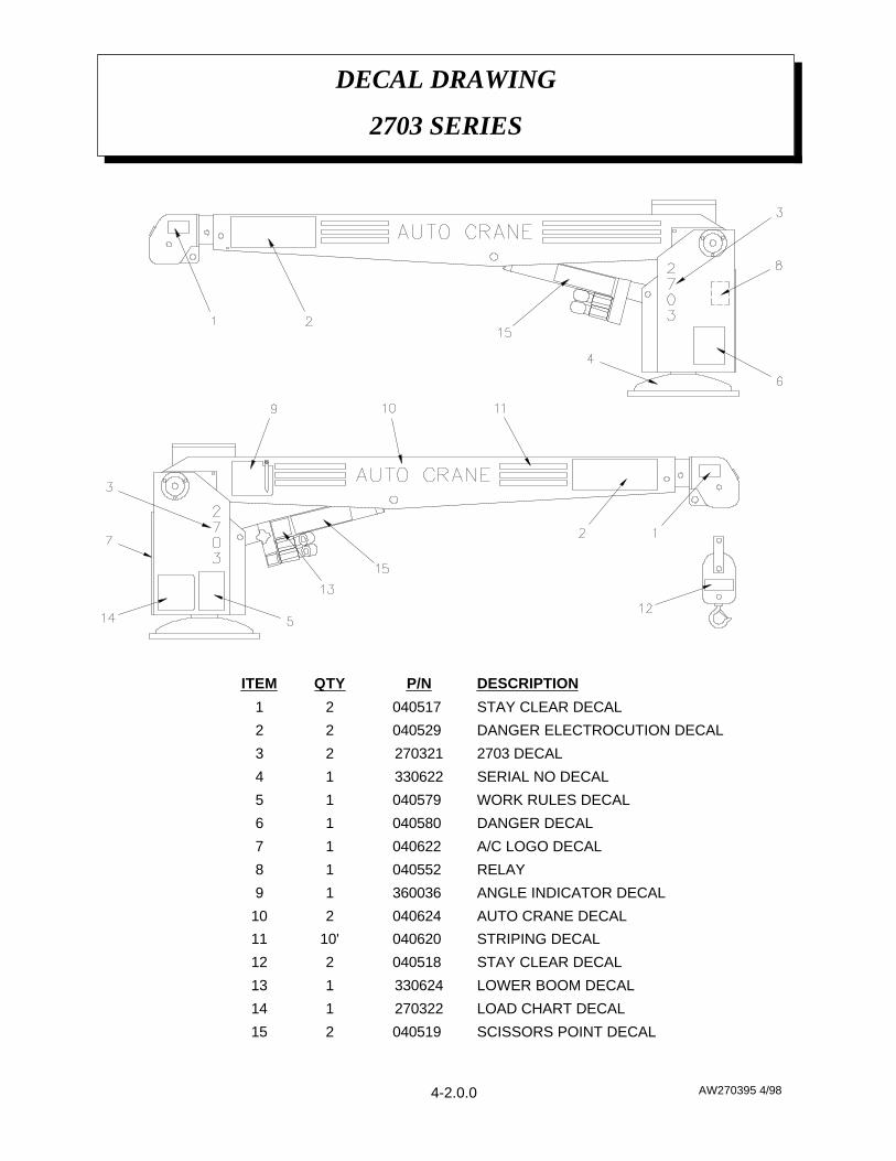
DECAL DRAWING
2703 SERIES
4-2.0.0
SCISSORS POINT DECAL040519 215
LOAD CHART DECAL270322114
LOWER BOOM DECAL330624113
STAY CLEAR DECAL040518 212
STRIPING DECAL040620 10'11
AUTO CRANE DECAL040624 210
ANGLE INDICATOR DECAL360036 19
RELAY040552 18
A/C LOGO DECAL040622 17
DANGER DECAL040580 16
WORK RULES DECAL040579 15
SERIAL NO DECAL33062214
2703 DECAL27032123
DANGER ELECTROCUTION DECAL040529 22
STAY CLEAR DECAL040517 21
DESCRIPTIONP/NQTYITEM
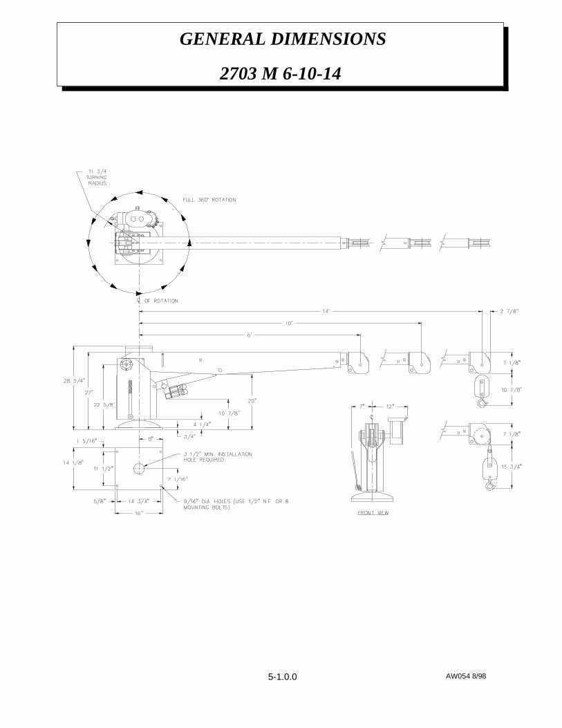
AW054 8/98
GENERAL DIMENSIONS
2703 M 6-10-14
5-1.0.0
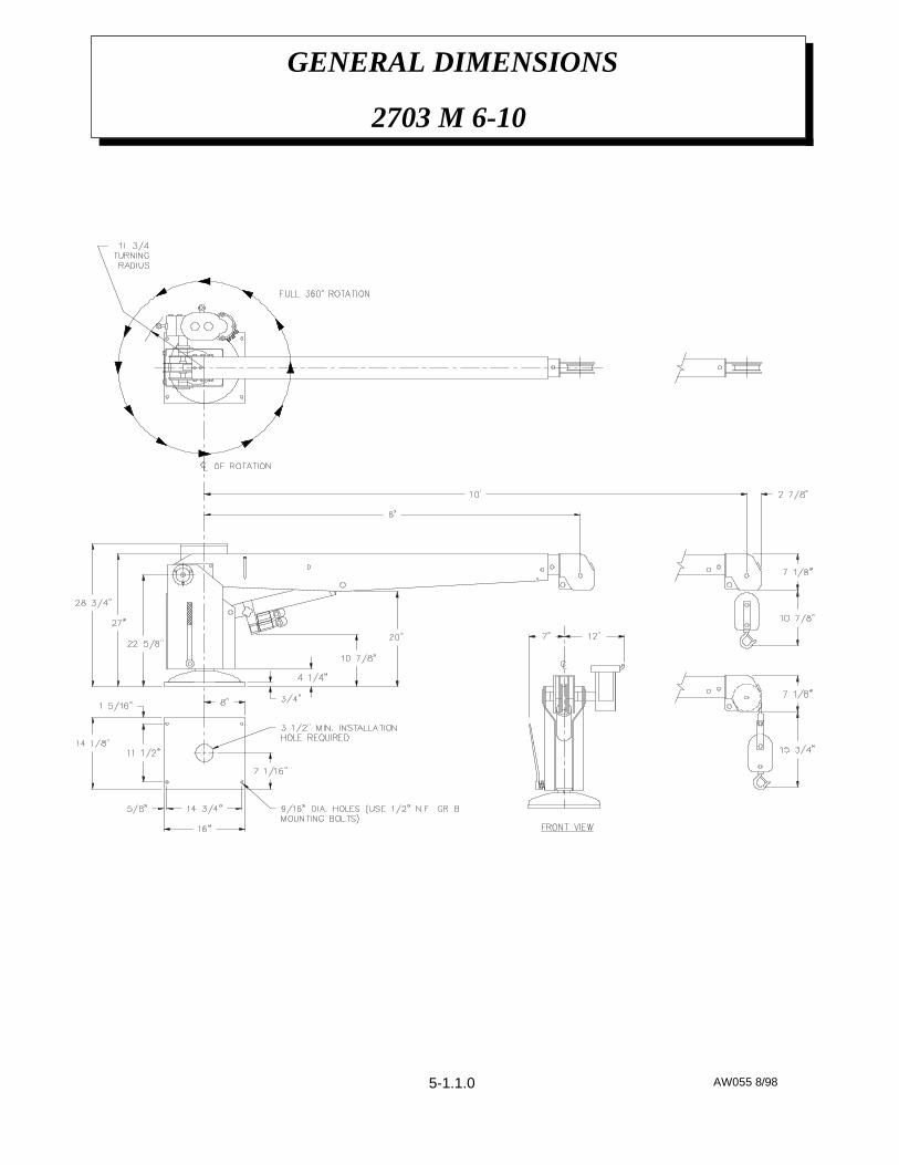
AW055 8/98
GENERAL DIMENSIONS
2703 M 6-10
5-1.1.0
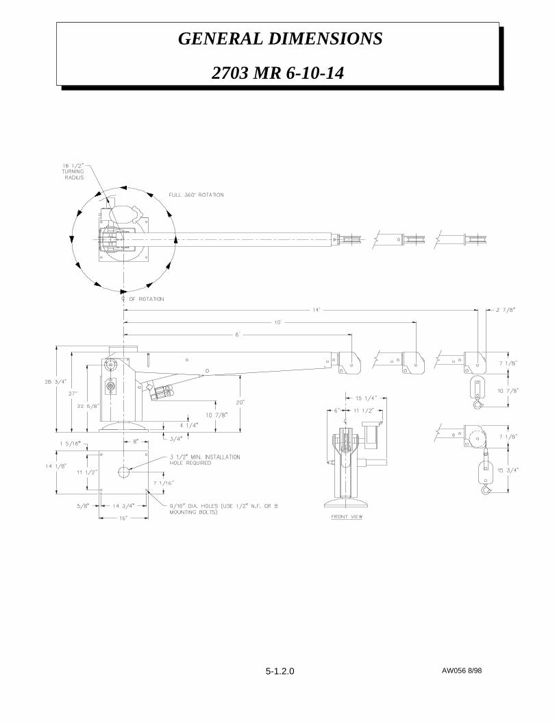
AW056 8/98
GENERAL DIMENSIONS
2703 MR 6-10-14
5-1.2.0
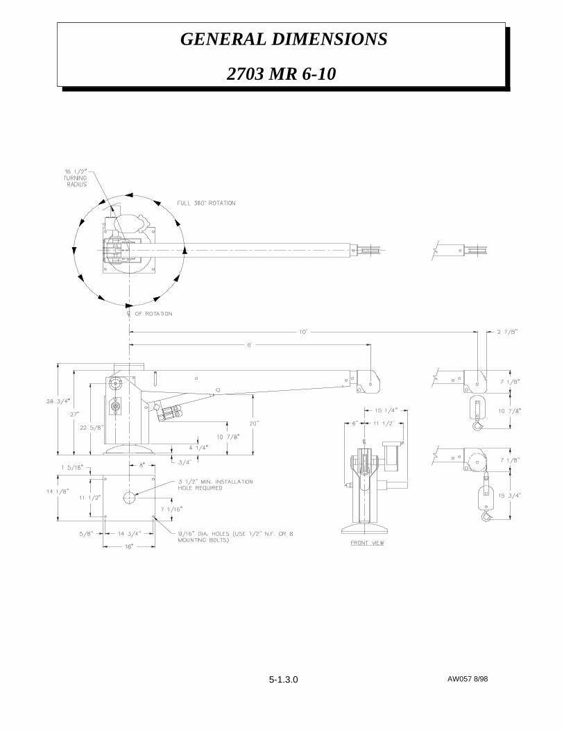
AW057 8/98
GENERAL DIMENSIONS
2703 MR 6-10
5-1.3.0
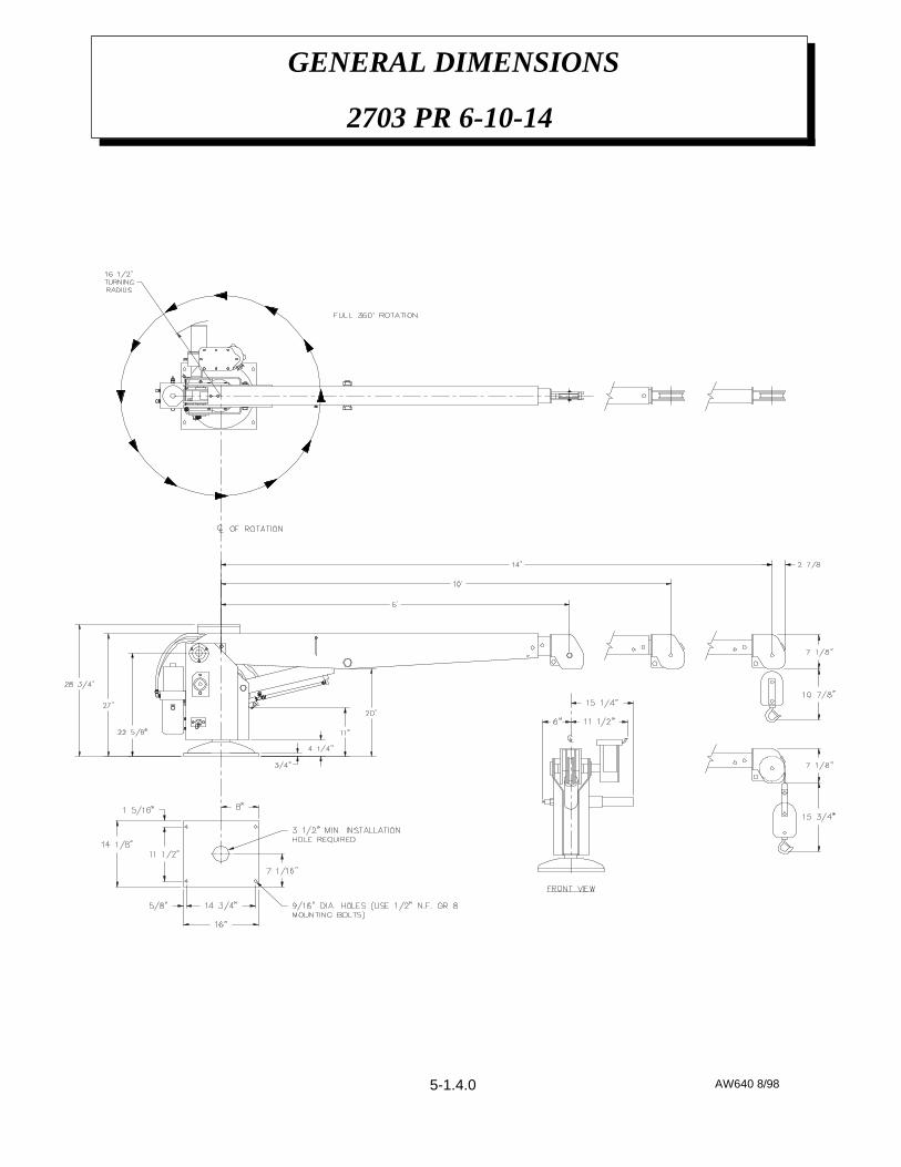
AW640 8/98
GENERAL DIMENSIONS
2703 PR 6-10-14
5-1.4.0

AW641 8/98
GENERAL DIMENSIONS
2703 PR 6-10
5-1.5.0

PENDANT ASSEMBLY BAYONET w/ 18' LG CABLE
P/N 270410 - 2703 PR
AW270410 8/986-1.0.0

PENDANT ASSEMBLY BAYONET w/ 18' LG CABLE
P/N 270410 - 2703 PR
AW270410 8/98
HEAT SHRINK TUBING4802436"21
WHITE WIRE 16GA x 38005920.2520
JUMPER BAR636600219
TOGGLE SWITCH634200118
CABLE CLAMP480515117
SCREW ST SLT PAN HD #8 x 1 1/2004700 116
3/4 WIDE OKONITE RUBBER TAPE8005801.7515
WASHER SP LK #8 PLATED019700 414
O-RING642100313
---12
TERMINALS T & B000101 1511
11 PIN BAYONET PLUG320563110
TY-RAP CABLE TIE63440129
CONDUCTOR CABLE80063018'8
CABLE ADAPTER63380117
SCREW ST SLT PAN HD #8 x 1 1/4005101 26
SCREW ST SLT PAN HD #6 x 3/4001004 105
BOOT-TOGGLE SWITCH64030034
TOGGLE SWITCH62200023
BOTTOM COVER63170012
PENDANT HOUSING63160211
DESCRIPTIONP/NQTYITEM
6-1.1.0

AW680068 3/98
PENDANT ASSEMBLY
P/N 680068 - 2703 MR
6-2.0.0
HEAT SHRINK TUBING490243 6"12
CABLE CLAMP480515 111
11 PIN BAYONET PLUG320563 110
PINION GEAR370135 29
TERMINAL RING000101 78
BOOT640302 27
RECESSED CROSS PAN HD SCREW #8 x1"001207 46
CONDUCTOR CABLE800629 17'5
TOGGLE SWITCH622000 24
PENDANT HOUSING GASKET370132 13
PENDANT COVER370131 12
PENDANT BOX370130 11
DESCRIPTIONP/NQTYITEM
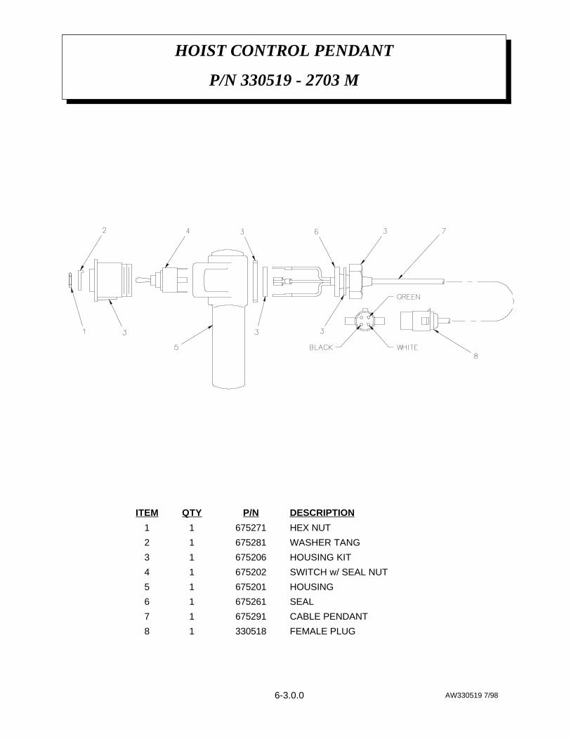
HOIST CONTROL PENDANT
P/N 330519 - 2703 M
AW330519 7/986-3.0.0
FEMALE PLUG33051818
CABLE PENDANT67529117
SEAL67526116
HOUSING67520115
SWITCH w/ SEAL NUT67520214
HOUSING KIT67520613
WASHER TANG67528112
HEX NUT67527111
DESCRIPTIONP/NQTYITEM

AW643 8/98
HYDRAULIC ASSEMBLY
2703 PR
6-4.0.0
LOCK WASHER 1/4020200215
HEX HD SCREW 1/4 x 2 1/2006700214
ELBOW JIC6/ORB6 LONG330645113
ADAPTER ST-6JIC200876112
PRESSURE SWITCH (REF)320543111
O-RING241169110
MANIFOLD SENSE VALVE36898519
ELBOW 90º -6 ORB / -6 JIC24117518
TEE STRAIGHT THREAD RUN20087717
HOLDING VALVE33041216
HOSE ASSEMBLY x 41812206-04125
ELBOW 90º 3/8 NPT / -6 JIC20089214
HOSE ASSEMBLY x 14812203-01413
HYDRAULIC CYLINDER33025012
HYDRAULIC PUMP27032411
DESCRIPTIONP/NQTYITEM

AW680052 3/98
RELAY ASSEMBLY BAYONET
P/N 680052 - 2703 MR
6-5.0.0

AW680052 3/98
RELAY ASSEMBLY BAYONET
P/N 680052 - 2703 MR
CONDUCTOR330415122
CONDUCTOR320564121
TWECO ASSEMBLY020001 820
CONDUCTOR015600 819
TERMINAL WIRE RB-14-10020700 1618
CONDUCTOR016800 1617
CONDUCTOR005604 816
CONDUCTOR015900 815
CONDUCTOR020200 814
CONDUCTOR680053113
CONDUCTOR330387112
CONDUCTOR330388111
CONDUCTOR330386110
TWECO ASSEMBLYREF 19
CONDUCTOR60030428
TERMINAL WIRE RB-14-10000300 17
CONDUCTOR62232716
CONDUCTOR62232325
CONDUCTOR65990444
CONDUCTOR65840023
CONDUCTOR65830042
RELAY20018241
DESCRIPTIONP/NQTYITEM
6-5.1.0
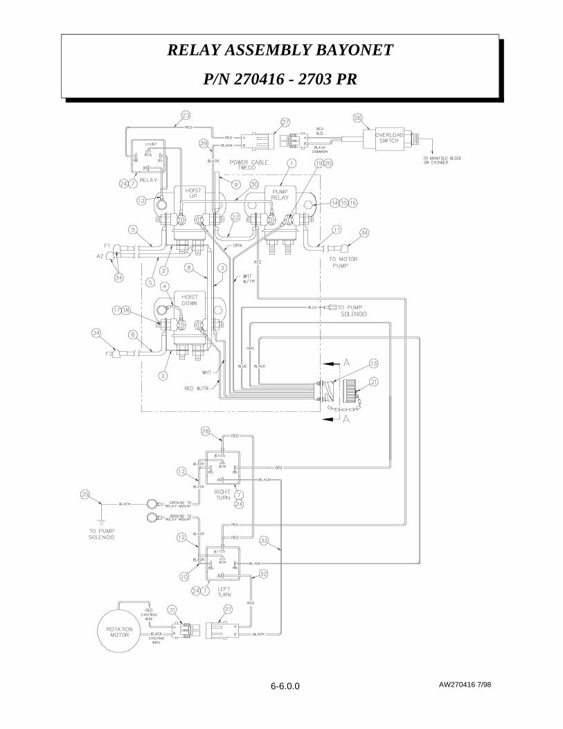
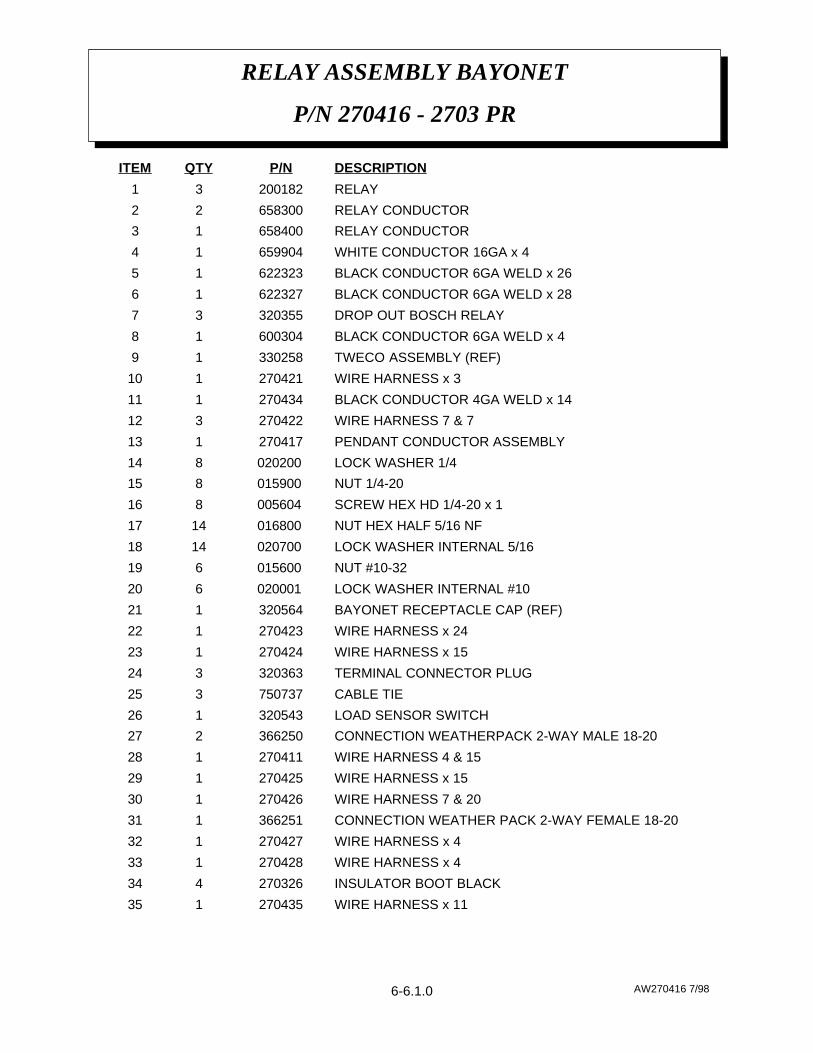
AW270416 7/98
RELAY ASSEMBLY BAYONET
P/N 270416 - 2703 PR
6-6.0.0
AW270416 7/98
RELAY ASSEMBLY BAYONET
P/N 270416 - 2703 PR
WIRE HARNESS x 11270435135
INSULATOR BOOT BLACK270326434
WIRE HARNESS x 4270428133
WIRE HARNESS x 4270427132
CONNECTION WEATHER PACK 2-WAY FEMALE 18-20366251131
WIRE HARNESS 7 & 20270426130
WIRE HARNESS x 15270425129
WIRE HARNESS 4 & 15270411128
CONNECTION WEATHERPACK 2-WAY MALE 18-20366250227
LOAD SENSOR SWITCH320543126
CABLE TIE750737325
TERMINAL CONNECTOR PLUG320363324
WIRE HARNESS x 15270424123
WIRE HARNESS x 24270423122
BAYONET RECEPTACLE CAP (REF)320564121
LOCK WASHER INTERNAL #10020001 620
NUT #10-32015600 619
LOCK WASHER INTERNAL 5/16020700 1418
NUT HEX HALF 5/16 NF016800 1417
SCREW HEX HD 1/4-20 x 1005604 816
NUT 1/4-20015900 815
LOCK WASHER 1/4020200 814
PENDANT CONDUCTOR ASSEMBLY270417113
WIRE HARNESS 7 & 7270422312
BLACK CONDUCTOR 4GA WELD x 14270434111
WIRE HARNESS x 3270421110
TWECO ASSEMBLY (REF)33025819
BLACK CONDUCTOR 6GA WELD x 460030418
DROP OUT BOSCH RELAY32035537
BLACK CONDUCTOR 6GA WELD x 2862232716
BLACK CONDUCTOR 6GA WELD x 2662232315
WHITE CONDUCTOR 16GA x 465990414
RELAY CONDUCTOR65840013
RELAY CONDUCTOR65830022
RELAY20018231
DESCRIPTIONP/NQTYITEM
6-6.1.0

PROBLEM CAUSE/SOLUTION
CRANE WILL NOT HOIST UP ORDOWN.
WITH LOAD SENSOR (OPT.)CRANE WILL NOT HOIST UP ORBOOM UP AND DOWN.
CRANE RUNS UP OR DOWN ANYTIME POWER SOURCE ISCONNECTED.
2703TRBL 4/98
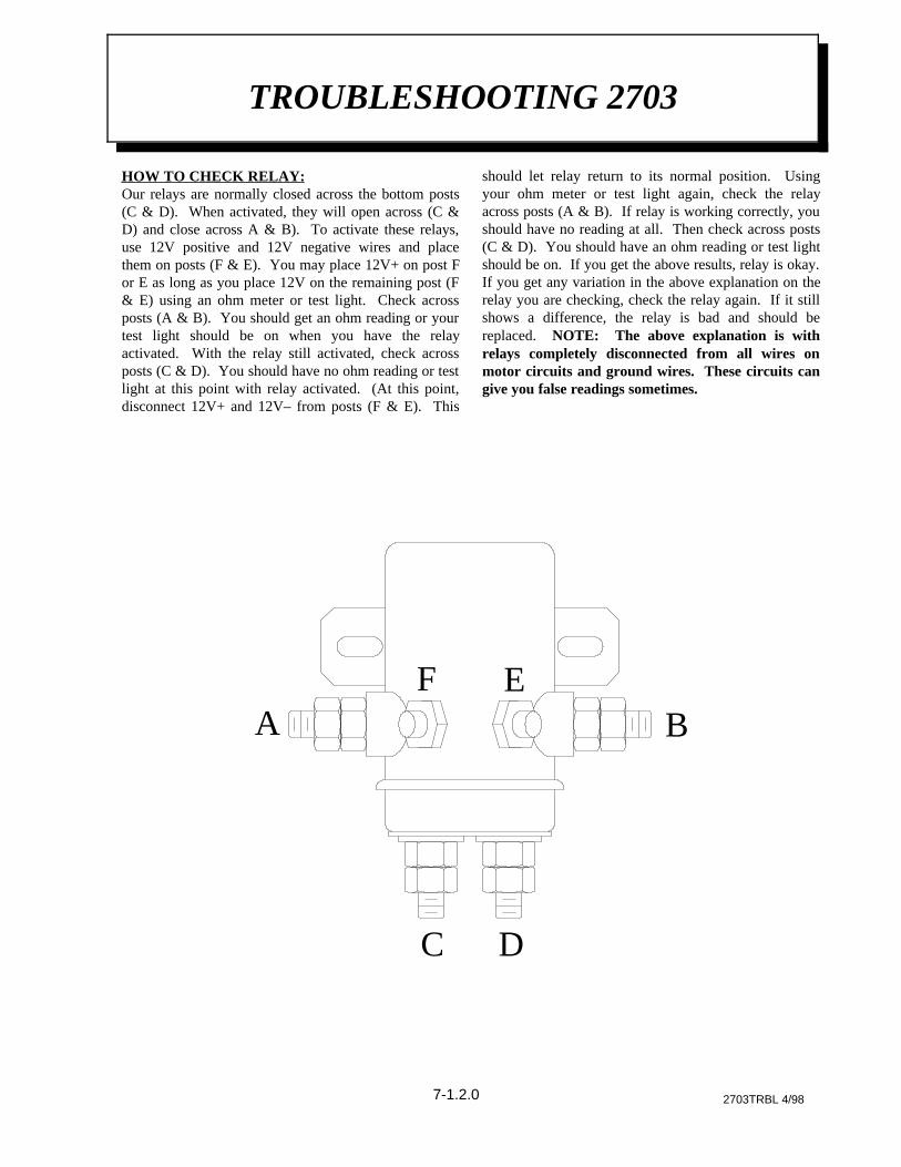
TROUBLESHOOTING 2703
CAUSE:Bad relay, crane not grounded properly, or power cable not connected to12V power source. Bad switch in pendant, broken wire in pendantconnector, pendant not plugged together properly, wire on relay not inproper place or lead wires to motor not connected properly.
SOLUTION:Problems can be solved by replacing bad relay, grounding the craneproperly to the truck chassis, connecting the power cable properly to 12V+power source, switch in pendant can be replaced, cord in remote controlcan be replaced, check connector on cord to make sure of contact of all theprongs on it are plugged together correctly, make sure wires on relays areaccording to the wiring print supplied with each new crane in the ownerbook and also wires going to motor are connected properly. NOTE: 12Vmust pass through opposite relay to complete circuit.
CAUSE:Crane is overloaded.Sensor switch is bad.Bad connection to relays.
SOLUTION:Hoist down. Do not overload crane. Replace sensor switch. Check forloose or damaged wiring.
7-1.0.0
CAUSE:Relay stuck in run position which will let crane run up or down any time12V power is connected. Wires shorted together in remote control. Leador cable can also cause this problem. Wires jumped across relay in wrongplace can cause crane to run all the time.
SOLUTION:Problem can be solved by checking the relays and replacing the bad oneor removing jumper wires from the relays or replacing the remote controlcord or switch.

PROBLEM CAUSE/SOLUTION
CRANE WILL NOT BOOM UP ORDOWN.
2703TRBL 4/98
TROUBLESHOOTING 2703
7-1.1.0
CAUSE:Bad pump, crane not grounded properly, or power cable not connected to12V power source. Bad switch in pendant, broken wire in pendantconnector, pendant not plugged together properly, wire on relay not inproper place or lead wires to motor not connected properly.
SOLUTION:Problems can be solved by replacing bad pump, grounding the craneproperly to the truck chassis, connecting the power cable properly to 12V+power source, switch in pendant can be replaced, cord in remote controlcan be replaced, check connector on cord to make sure of contact of all theprongs on it are plugged together correctly, make sure wires on relays areaccording to the wiring print supplied with each new crane in the ownerbook and also wires going to motor are connected properly.
2703TRBL 4/98
TROUBLESHOOTING 2703
AF E
B
C D
7-1.2.0
HOW TO CHECK RELAY:Our relays are normally closed across the bottom posts(C & D). When activated, they will open across (C &D) and close across A & B). To activate these relays,use 12V positive and 12V negative wires and placethem on posts (F & E). You may place 12V+ on post For E as long as you place 12V on the remaining post (F& E) using an ohm meter or test light. Check acrossposts (A & B). You should get an ohm reading or yourtest light should be on when you have the relayactivated. With the relay still activated, check acrossposts (C & D). You should have no ohm reading or testlight at this point with relay activated. (At this point,disconnect 12V+ and 12V– from posts (F & E). This
should let relay return to its normal position. Usingyour ohm meter or test light again, check the relayacross posts (A & B). If relay is working correctly, youshould have no reading at all. Then check across posts(C & D). You should have an ohm reading or test lightshould be on. If you get the above results, relay is okay.If you get any variation in the above explanation on therelay you are checking, check the relay again. If it stillshows a difference, the relay is bad and should bereplaced. NOTE: The above explanation is withrelays completely disconnected from all wires onmotor circuits and ground wires. These circuits cangive you false readings sometimes.

AW270322 8/98
LOAD CHART
2703 SERIES
9-9.9.9


![Future Met Support pdfH1]Future Met Sup… · TEMPO 2612/2618 4000 SHRA TEMPO 2618/2703 VRB15G25KT 2500 TSRA SHRA FEW010CB SCT020 BECMG 2703/2705 17010KT TEMPO 2703/2709 4000 SHRA.](https://static.fdocuments.us/doc/165x107/5f771d8831489a73372870e6/future-met-support-h1future-met-sup-tempo-26122618-4000-shra-tempo-26182703.jpg)