Auto Dimensioning a Drawing - World Class...
23
9-1 C h a p t e r 9 Auto Dimensioning a Drawing In this chapter, you will learn how to use the following AutoLISP functions to World Class standards: ! Adding Dimensions to a Drawing Automatically ! Starting the Rectangle_Shim Code ! Saving the Object Snap Settings and then Turning Them Off ! Using Getpoint to Obtain a Point on the Graphical Display ! Using Getreal to Obtain a Real Number from the Keyboard ! Creating Layers with the Visual AutoLISP Command Function ! Doing the Math in Visual AutoLISP ! Making Point Assignments in Visual AutoLISP ! Drawing in Visual AutoLISP ! Ending the Program ! Saving the Program ! Adding Dimension Centerlines to a Drawing ! Adding Linear Dimensions to a Drawing ! Adding a Diameter Dimension to a Drawing ! Loading the Program ! Running the Program
Transcript of Auto Dimensioning a Drawing - World Class...

9-1
C h a p t e r 9
Auto Dimensioning a Drawing
In this chapter, you will learn how to use the following AutoLISP functions to World Class standards: ! Adding Dimensions to a Drawing Automatically ! Starting the Rectangle_Shim Code ! Saving the Object Snap Settings and then Turning Them Off ! Using Getpoint to Obtain a Point on the Graphical Display ! Using Getreal to Obtain a Real Number from the Keyboard ! Creating Layers with the Visual AutoLISP Command Function ! Doing the Math in Visual AutoLISP ! Making Point Assignments in Visual AutoLISP ! Drawing in Visual AutoLISP ! Ending the Program ! Saving the Program ! Adding Dimension Centerlines to a Drawing ! Adding Linear Dimensions to a Drawing ! Adding a Diameter Dimension to a Drawing ! Loading the Program ! Running the Program

9-2
Adding Dimensions to a Drawing Automatically _________________________________________________________ In this chapter, we will venture to accomplish another level in drawing automation by having the program dimension of the part. We can achieve this goal by utilizing many of the same skills that we have learned in the previous chapters. We start out the drawing by creating a sketch, labeling the sketch, and writing the construction code to automatically create the part. What will be new in our code is a small section that will place center lines, horizontal and vertical dimensions and leaders that will denote the diameter of a hole. Once we understand the simplicity of adding dimensions on the dimensional layer then we will add them to our programs without hesitation and our drawings will be completed that much sooner.
Figure 9.1 � Sketch of the Rectangle_shim
Step 1 Start the program Step 2 Drawing setup Step 3 User input Step 4 Do the math Step 5 Point assignments Step 6 Lets draw
Repeat Steps 4-6
Add dimensions Math, Point Assignment, Draw Dimensions
Step 7 End the program Figure 9.2 � Steps for Creating Dimensions in Construction Code
9-3
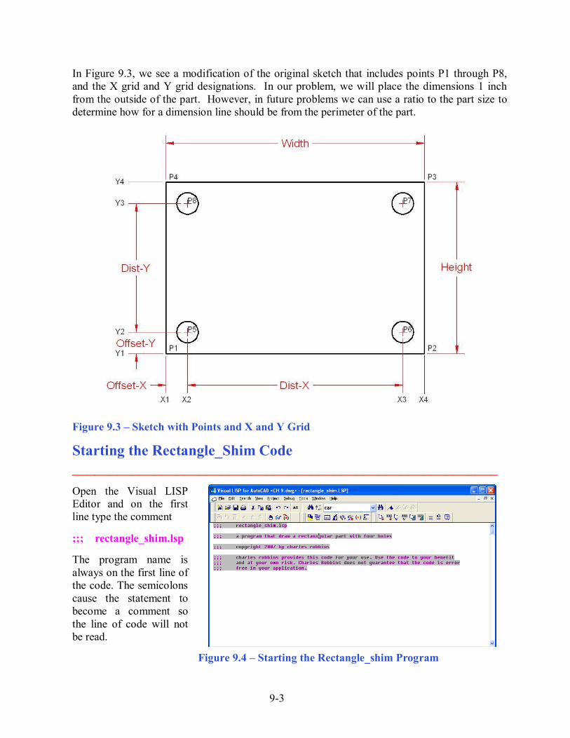
In Figure 9.3, we see a modification of the original sketch that includes points P1 through P8, and the X grid and Y grid designations. In our problem, we will place the dimensions 1 inch from the outside of the part. However, in future problems we can use a ratio to the part size to determine how for a dimension line should be from the perimeter of the part.
Figure 9.3 � Sketch with Points and X and Y Grid
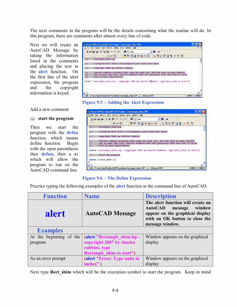
Starting the Rectangle_Shim Code _________________________________________________________ Open the Visual LISP Editor and on the first line type the comment ;;; rectangle_shim.lsp The program name is always on the first line of the code. The semicolons cause the statement to become a comment so the line of code will not be read.
Figure 9.4 � Starting the Rectangle_shim Program
9-4
The next comments in the program will be the details concerning what the routine will do. In this program, there are comments after almost every line of code. Next we will create an AutoCAD Message by taking the information listed in the comments and placing the text in the alert function. On the first line of the alert expression, the program and the copyright information is keyed.
Figure 9.5 � Adding the Alert Expression
Add a new comment ;;; start the program Then we start the program with the defun function, which means define function. Begin with the open parenthesis then defun, then a c: which will allow the program to run on the AutoCAD command line. Figure 9.6 � The Defun Expression
Practice typing the following examples of the alert function at the command line of AutoCAD.
Function Name Description
alert AutoCAD Message
The alert function will create an AutoCAD message window appear on the graphical display with an OK button to close the message window.
Examples At the beginning of the program
(alert "Rectangle_shim.lsp - copyright 2007 by charles robbins. type Rectangle_shim to start")
Window appears on the graphical display
As an error prompt (alert "Error: Type units in inches� )
Window appears on the graphical display
Next type Rect_shim which will be the execution symbol to start the program. Keep in mind
9-5
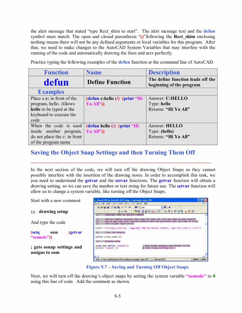
the alert message that stated �type Rect_shim to start�. The alert message text and the defun symbol must match. The open and closed parenthesis �()�following the Rect_shim enclosing nothing means there will not be any defined arguments or local variables for this program. After that, we need to make changes to the AutoCAD System Variables that may interfere with the running of the code and automatically drawing the lines and arcs perfectly. Practice typing the following examples of the defun function at the command line of AutoCAD.
Function Name Description
defun Define Function The define function leads off the beginning of the program
Examples Place a c: in front of the program, hello. Allows hello to be typed at the keyboard to execute the code
(defun c:hello (/) (print �Hi Ya All�))
Answer: C:HELLO Type: hello Returns: �Hi Ya All�
When the code is used inside another program, do not place the c: in front of the program name
(defun hello (/) (print �Hi Ya All�))
Answer: HELLO Type: (hello) Returns: �Hi Ya All�
Saving the Object Snap Settings and then Turning Them Off _________________________________________________________ In the next section of the code, we will turn off the drawing Object Snaps so they cannot possibly interfere with the insertion of the drawing notes. In order to accomplish this task, we you need to understand the getvar and the setvar functions. The getvar function will obtain a drawing setting, so we can save the number or text string for future use. The setvar function will allow us to change a system variable, like turning off the Object Snaps. Start with a new comment ;;; drawing setup And type the code (setq osm (getvar �osmode�)) ; gets osnap settings and assigns to osm
Figure 9.7 � Saving and Turning Off Object Snaps Next, we will turn off the drawing�s object snaps by setting the system variable �osmode� to 0 using this line of code. Add the comment as shown.

9-6
(setvar �osmode� 0) ; turns osnap settings off Let�s talk about the expression, (setq osm (getvar �osmode�)). The function setq means set quotient and we will use the function to create a variable osm which stands for object snap mode, a variable name that we just made up. The variable osm will hold the integer representing the �osmode� system variable�s setting. To get the number use the function getvar followed by the name of system variable inside a set of quotes. To turn off a system variable in many cases in setting the variable to zero. In the expression, (setvar �osmode� 0), the function setvar followed by a system variable inside a set of quotes like �osmode� then a 0 will result in turning off the Object Snap settings. Practice typing the following examples of the setq, getvar and setvar functions at the command line of AutoCAD.
Function Name Description
setq Set Quotient Allows the user to assign a real number, integer, string or list to a variable
Examples Set the variable a the text string World Class CAD
(setq a �World Class CAD�)
Answer: �World Class CAD�
Set the variable counter the integer 0
(setq counter 0)
Answer: 0
Set the text height variable txtht the real number 0.125
(setq txtht 0.125)
Answer: 0.1250
Set the point variable sp the list of 0,0,0
(setq sp (list 0.0 0.0 0.0))
Answer: (0,0,0)
Function Name Description
getvar Get a variable Allows the user to obtain a system variable setting from an AutoCAD drawing
Examples Turn on the endpoint, midpoint, quadrant, intersection and perpendicular Object Snaps
(setq osm (getvar �osmode�)) Answer: 179
Get the AutoCAD version number
(setq osm (getvar �acadver�)) Answer: "16.2s (LMS Tech)"

9-7
Function Name Description
setvar Get a variable Allows the user to obtain a system variable setting from an AutoCAD drawing
Examples Turn off the Object Snaps
(setvar �osmode� 0)) Answer: 0
Using Getpoint to Obtain a Point on the Graphical Display _________________________________________________________ In the User Input section of the Construction Code, we need to expand into new areas besides just requesting the starting point and the getting a measurement using the getreal function as we did in the first eight programs. The first function we will examine together is getpoint. This tool will allow the program user to select a point on the graphical display with their mouse. Following getpoint is a text string usually written is a commanding or questioning format.
Figure 9.8 � Using the Getpoint Function The user input of selecting a point begins with a comment. ;;; user input Then type the following code:
(setq sp (getpoint �\nPick the starting point �)) We use the setq expression to assign the three point list (X, Y and Z) to the variable sp representing the starting point. After the function getpoint, a programmer has the option, in which we have chosen, to add a line of text prompting the user to �Pick the starting point� and we also modified the prompt in a small way. Notice that in front of the capital P in the word Pick, a �\n� is added. That will place the command �Pick the starting point� without containing those two characters to start on a new command line in the AutoCAD program. Placing command statements or questions on a new command line allows for a cleaner look to the user when following a command or answering the question.
9-8
Periodically we will work at an organization that wants their notes in the exact location of their drawing. When we face a programming problem such as this the starting point expression will change. First instance, let us make believe that the notes at this company start at the X and Y coordinates 14, 10. Then in this note making code, we would change the starting point expression to:
(setq sp (list 14 10 0))
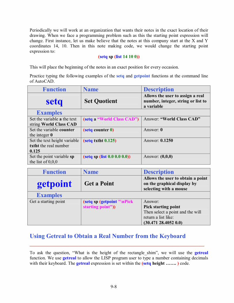
This will place the beginning of the notes in an exact position for every occasion. Practice typing the following examples of the setq and getpoint functions at the command line of AutoCAD.
Function Name Description
setq Set Quotient Allows the user to assign a real number, integer, string or list to a variable
Examples Set the variable a the text string World Class CAD
(setq a �World Class CAD�)
Answer: �World Class CAD�
Set the variable counter the integer 0
(setq counter 0)
Answer: 0
Set the text height variable txtht the real number 0.125
(setq txtht 0.125)
Answer: 0.1250
Set the point variable sp the list of 0,0,0
(setq sp (list 0.0 0.0 0.0))
Answer: (0,0,0)
Function Name Description
getpoint Get a Point Allows the user to obtain a point on the graphical display by selecting with a mouse
Examples Get a starting point (setq sp (getpoint "\nPick
starting point")) Answer: Pick starting point Then select a point and the will return a list like: (30.471 28.4052 0.0)
Using Getreal to Obtain a Real Number from the Keyboard _________________________________________________________ To ask the question, �What is the height of the rectangle_shim�, we will use the getreal function. We use getreal to allow the LISP program user to type a number containing decimals with their keyboard. The getreal expression is set within the (setq height ��. ) code.

9-9
The information that the user types with the keyboard is stored in the variable name height. We will never pick a variable name that matches an AutoCAD command. So type the following compound expression:
Figure 9.9 � Using the Getreal Function
(setq height (getreal �\nWhat is the height of the rectangle_shim? �))
Whenever we are not quite sure whether the answer is going to be a whole number or a decimal, we will use the getreal function. Using another function which will only allow whole numbers will never allow the acceptance of a decimal. If you look at the Visual LISP Editor in Figure 9.9, you will notice that we dressed the expressions so that the questions line up perfectly. You will pick up on this characteristic when the program is running and the typed answers to the questions line up neatly. Practice typing the following examples of the getreal function at the command line of AutoCAD.
Function Name Description
getreal Get a Real Number Allows the user to obtain a real number by allowing the user to type at the keyboard
Examples
Get a number (setq txtht (getreal "\nWhat is the text height?�))
Answer: What is the text height? Then type: 0.125 3.2
Ask for a number, user types a whole number and the reply is changed to a real number
(setq txtht (getreal "\nWhat is the text height?�))
Answer: What is the text height? Then type: 1 1.0
Ask for a number, user types a fraction and the reply is changed to a real number
(setq txtht (getreal "\nWhat is the text height?�))
Answer: What is the text height? Then type: 1/8 0.125

9-10
Creating Layers with the Visual AutoLISP Command Function _________________________________________________________ In all of the other Visual AutoLISP programs, we run the code on the layer that we want to have the orthographic view or notes. In this detail, we will place the entities on unique layers such as footer, block, wood, dimension and text. Then we will lame addition layers for center, hidden and section lines.
Figure 9.10 � Creating Layers in AutoLISP An easy way to make a layer for a detail is to use the command function and to follow the creating a new layer process. This can be harder for individuals just newly training with AutoCAD, since many computer aided design tools are now in dialogue boxes and we cannot easily view all the options that are available with a command function. We will share the most common options in the table below.
Command Layer Function Command Layer Function (command "layer" "n" "plate" ��) Makes a new layer named �plate�
(command "layer" "c" "8" �plate" ��) Sets the layer color to �color 8� for layer named �plate�
(command "layer" "lt" "center" �center" "")
Sets the layer linetype to �center� for layer named �center�
(command "layer" "s" "plate" ��) Sets the current layer as �plate� (command "layer" "f" "plate" ��) Freezes the layer named �plate� (command "layer" "t" "plate" ��) Thaws the layer named �plate� (command "layer" "on" "plate" ��) Turns the layer named �plate� on (command "layer" "off" "plate" ��) Turns the layer named �plate� off (command "layer" "lo" "plate" ��) Locks the layer named �plate� (command "layer" "u" "plate" ��) Unlocks the layer named �plate�
We can combine layer options such as new and color and create a command line expression that will both create a new layer and set the color for that layer. When we use the color option "c", the next item is the name or number of the color, followed by the name of the layer. To end the layer command expression, place an open and closed quote "" at the end of the code and then a closed parenthesis. Type the following lines in the rectangle_shim program.
9-11
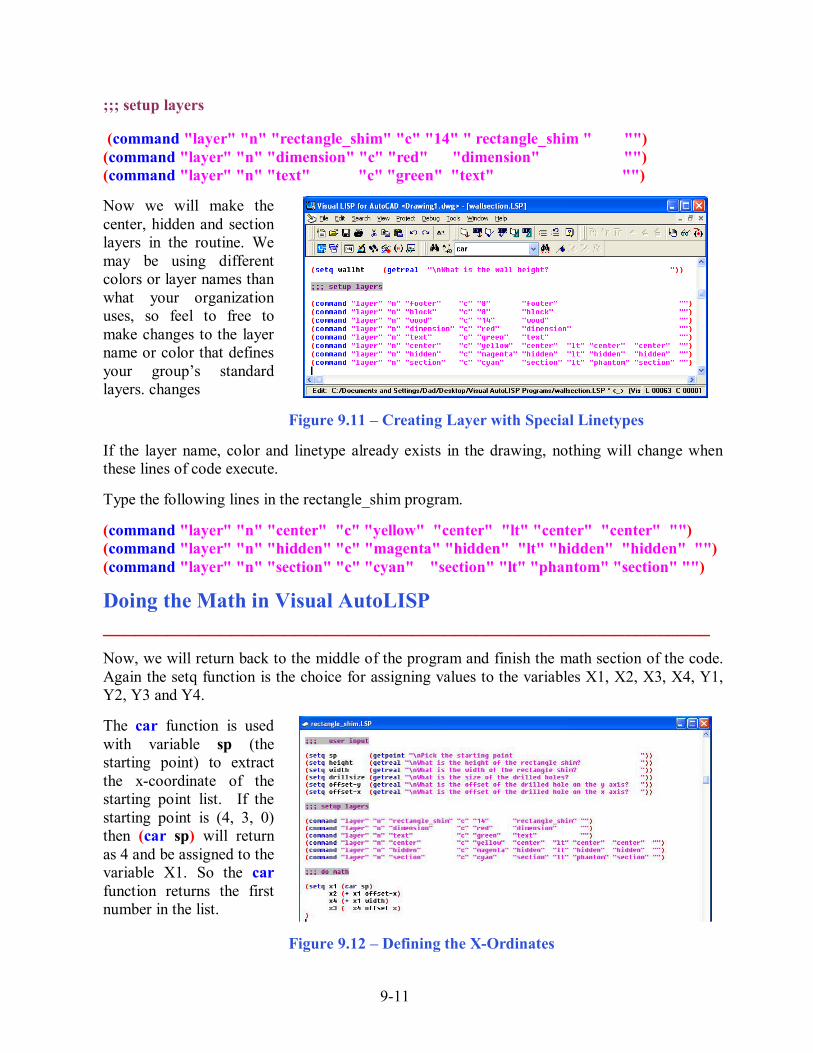
;;; setup layers (command "layer" "n" "rectangle_shim" "c" "14" " rectangle_shim " "") (command "layer" "n" "dimension" "c" "red" "dimension" "") (command "layer" "n" "text" "c" "green" "text" "") Now we will make the center, hidden and section layers in the routine. We may be using different colors or layer names than what your organization uses, so feel to free to make changes to the layer name or color that defines your group�s standard layers. changes Figure 9.11 � Creating Layer with Special Linetypes If the layer name, color and linetype already exists in the drawing, nothing will change when these lines of code execute. Type the following lines in the rectangle_shim program. (command "layer" "n" "center" "c" "yellow" "center" "lt" "center" "center" "") (command "layer" "n" "hidden" "c" "magenta" "hidden" "lt" "hidden" "hidden" "") (command "layer" "n" "section" "c" "cyan" "section" "lt" "phantom" "section" "")
Doing the Math in Visual AutoLISP _________________________________________________________ Now, we will return back to the middle of the program and finish the math section of the code. Again the setq function is the choice for assigning values to the variables X1, X2, X3, X4, Y1, Y2, Y3 and Y4. The car function is used with variable sp (the starting point) to extract the x-coordinate of the starting point list. If the starting point is (4, 3, 0) then (car sp) will return as 4 and be assigned to the variable X1. So the car function returns the first number in the list.
Figure 9.12 � Defining the X-Ordinates

9-12
That explains the use of car to find the coordinates x1, now we have to continue down the X grid to obtain value for x2. To obtain the x2 coordinate, use the addition function + to add offset-x to the x1 value. Type the following lines in the rectangle_shim program using the sketch in Figure 9.2 to find the X ordinate the dimension that defines the horizontal measurements. ;;; math (setq x1 (car sp) x2 (+ x1 offset-x) x4 (+ x1 width) x3 (+ x4 offset-x) ) Likewise, the cadr function is used with variable sp (the starting point) to extract the y-coordinate of the starting point. Again, if the starting point is (4, 3, 0) then (cadr sp) will return as 3 and be assigned to the variable y1. So the cadr function returns the second number in the list. Figure 9.13 � Defining the Y-Ordinates To find the value for the adaptable y2, we add the variable for the offset-y height. We use the adding LISP function + to make the expression
y2 (+ y1 offset-y) Type the following lines in the rectangle_shim program using the sketch in Figure 9.2 to find the Y ordinate the dimension that defines the vertical measurements.
(setq y1 (cadr sp) y2 (+ y1 offset-y) y4 (+ y1 height) y3 (+ y4 offset-y) )
9-13
Making Point Assignments in Visual AutoLISP _________________________________________________________
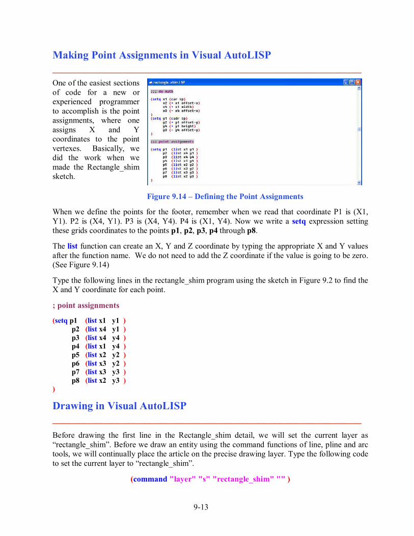
One of the easiest sections of code for a new or experienced programmer to accomplish is the point assignments, where one assigns X and Y coordinates to the point vertexes. Basically, we did the work when we made the Rectangle_shim sketch.
Figure 9.14 � Defining the Point Assignments When we define the points for the footer, remember when we read that coordinate P1 is (X1, Y1). P2 is (X4, Y1). P3 is (X4, Y4). P4 is (X1, Y4). Now we write a setq expression setting these grids coordinates to the points p1, p2, p3, p4 through p8. The list function can create an X, Y and Z coordinate by typing the appropriate X and Y values after the function name. We do not need to add the Z coordinate if the value is going to be zero. (See Figure 9.14) Type the following lines in the rectangle_shim program using the sketch in Figure 9.2 to find the X and Y coordinate for each point. ; point assignments (setq p1 (list x1 y1 )
p2 (list x4 y1 ) p3 (list x4 y4 ) p4 (list x1 y4 ) p5 (list x2 y2 ) p6 (list x3 y2 ) p7 (list x3 y3 ) p8 (list x2 y3 )
)
Drawing in Visual AutoLISP _________________________________________________________ Before drawing the first line in the Rectangle_shim detail, we will set the current layer as �rectangle_shim�. Before we draw an entity using the command functions of line, pline and arc tools, we will continually place the article on the precise drawing layer. Type the following code to set the current layer to �rectangle_shim�.
(command "layer" "s" "rectangle_shim" "" )
9-14
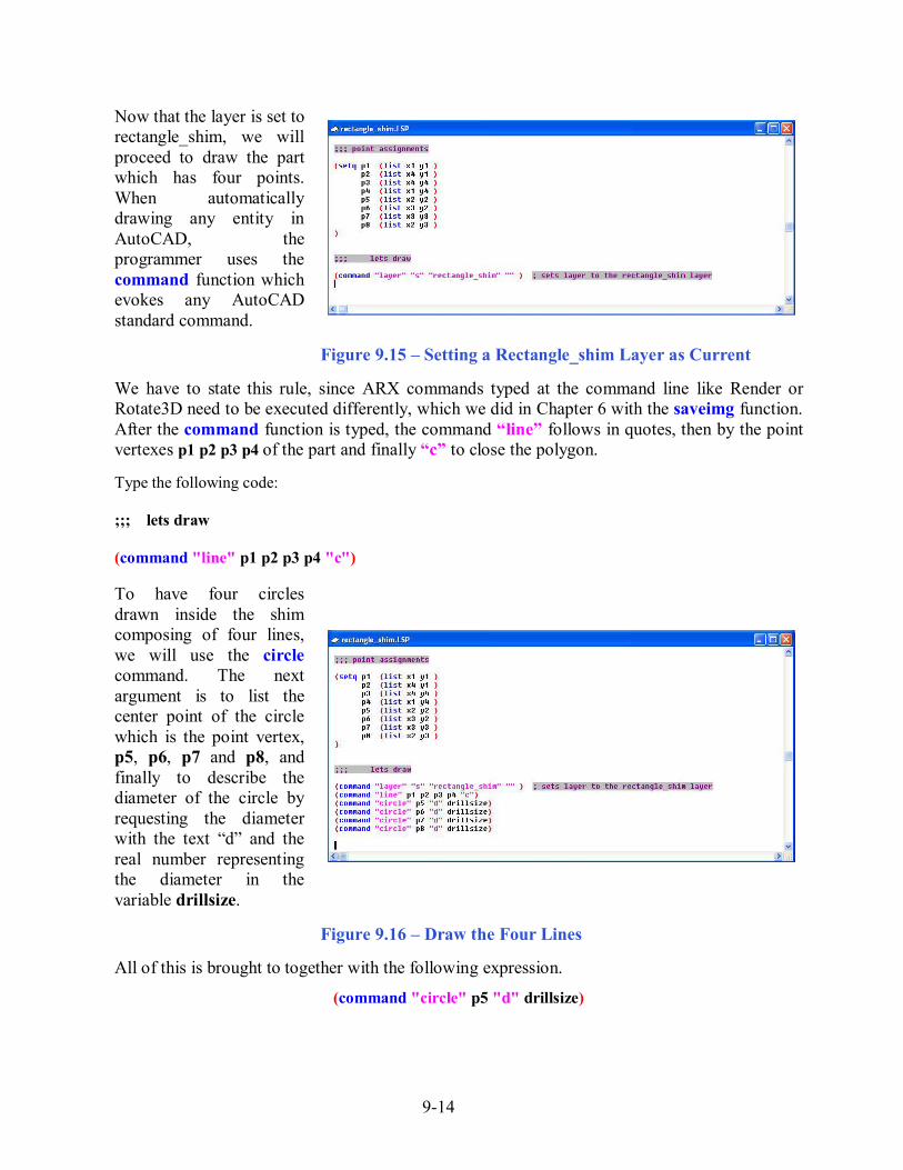
Now that the layer is set to rectangle_shim, we will proceed to draw the part which has four points. When automatically drawing any entity in AutoCAD, the programmer uses the command function which evokes any AutoCAD standard command.
Figure 9.15 � Setting a Rectangle_shim Layer as Current We have to state this rule, since ARX commands typed at the command line like Render or Rotate3D need to be executed differently, which we did in Chapter 6 with the saveimg function. After the command function is typed, the command �line� follows in quotes, then by the point vertexes p1 p2 p3 p4 of the part and finally �c� to close the polygon. Type the following code: ;;; lets draw (command "line" p1 p2 p3 p4 "c") To have four circles drawn inside the shim composing of four lines, we will use the circle command. The next argument is to list the center point of the circle which is the point vertex, p5, p6, p7 and p8, and finally to describe the diameter of the circle by requesting the diameter with the text �d� and the real number representing the diameter in the variable drillsize.
Figure 9.16 � Draw the Four Lines All of this is brought to together with the following expression.
(command "circle" p5 "d" drillsize)
9-15
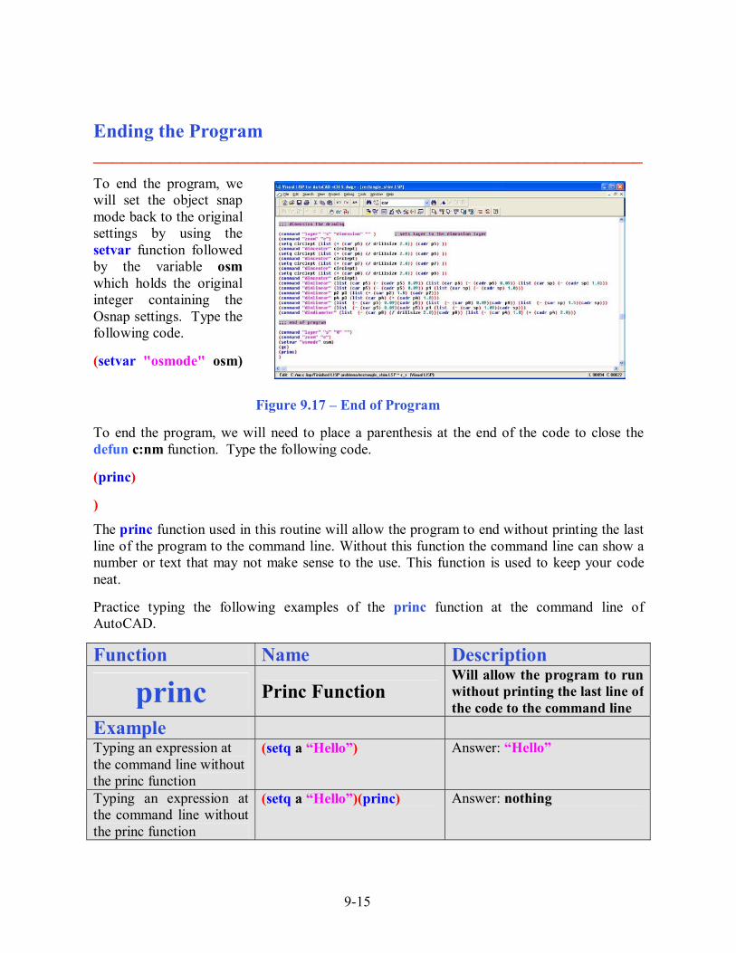
Ending the Program _________________________________________________________ To end the program, we will set the object snap mode back to the original settings by using the setvar function followed by the variable osm which holds the original integer containing the Osnap settings. Type the following code. (setvar "osmode" osm) Figure 9.17 � End of Program To end the program, we will need to place a parenthesis at the end of the code to close the defun c:nm function. Type the following code. (princ) )
The princ function used in this routine will allow the program to end without printing the last line of the program to the command line. Without this function the command line can show a number or text that may not make sense to the use. This function is used to keep your code neat. Practice typing the following examples of the princ function at the command line of AutoCAD.
Function Name Description
princ Princ Function Will allow the program to run without printing the last line of the code to the command line
Example
Typing an expression at the command line without the princ function
(setq a �Hello�) Answer: �Hello�
Typing an expression at the command line without the princ function
(setq a �Hello�)(princ) Answer: nothing

9-16
Saving the Program _________________________________________________________ Now that the program is finished, we need to double check our typing with the text in this manual and then save our program to our folder named �Visual AutoLISP Programs�.
Make sure the Look in list box is displaying the Visual LISP Programs folder and then select the program �rectangle_shim� and press the Load button. At the bottom � left corner of the Load / Unload Applications window you will see a small text display that was blank initially but now displays the text as shown in Figure 9.18,
�rectangle_shim.LSP successfully loaded�
Figure 9.18 � Loading the Rectangle_shim Program After noting that the program is loaded, press the Close button and now when you are in the AutoCAD program, an AutoCAD message window appears in the middle of the graphics display. The copyright and information to start the program is shown.
Figure 9.19 � The Alert Message
At World Class CAD, we will run the program as written and correct any errors that we find in creating the part, so that when we add the dimension code, we already know that the initial program is error free.
Now we will add the dimensions.

9-17
Adding Dimension Centerlines to a Drawing _________________________________________________________
We begin by setting the dimensional layer. Type the following code and comment as shown in Figure 9.20. (command "layer" "s" "dimension" "" ) ; sets layer to the dimension layer Figure 9.20 � Setting the Dimension Layer To place a center mark on a circle, we will select the circle by placing the pick box on the entity. We will accomplish this task by building a new point from the center of a circle. We will start with the first circle and the centerpoint P5. The new point will have an X ordinate that is half of the drillsize and the Y ordinate that is the same as P5. We will assign the new point to the variable circlept. Write the following code.
(setq circlept (list (+ (car p5) (/ drillsize 2.0)) (cadr p5) )) To place the center mark, type the following code.
(command "dimcenter" circlept) Each time the variable circlept will be redefined for the other holes, P6, P7 and finally P8. Type the following lines of code.
(setq circlept (list (+ (car p6) (/ drillsize 2.0)) (cadr p6) )) (command "dimcenter" circlept) (setq circlept (list (+ (car p7) (/ drillsize 2.0)) (cadr p7) )) (command "dimcenter" circlept) (setq circlept (list (+ (car p8) (/ drillsize 2.0)) (cadr p8) )) (command "dimcenter" circlept)
We continue to arrange similar lines of code as shown in figure 9.21, so the syntax of the program is simple to check. We can easily spot errors in these programming expressions since they are aligned.
Figure 9.21 � Inserting Dimension Center Marks

9-18
Adding Linear Dimension to a Drawing _________________________________________________________ When we add the linear dimensions, first we will reset the dimension extension offset, dimexo, so that the dimension extension lines do not overlap the center marks. Before changing the system variable, we will save the old setting to the variable offorigin. For this drawing, we will set the new dimension extension line offset to 0.1875. Type the following lines of code.
(setq offorigin (getvar "dimexo")) (setvar "dimexo" 0.1875)
When we dimension with linear dimensions, we select two points that represent the linear distance we wish to measure. The third point selection is to place the dimension. We are going to select the points defined in the sketch shown in figure 9.2. For our third point, we will create a new point with the list function that is one inch off the part�s perimeter. We will add one inch to the X ordinate to place the dimension on the right side of the part. We will add one inch to the Y ordinate to place the dimension on the top side of the part. We will subtract one inch to the X ordinate to place the dimension on the left side of the part. We will subtract one inch to the Y ordinate to place the dimension on the bottom side of the part. Type the following lines of code.
(command "dimlinear" p5 p6 (list (car p1) (- (cadr p1) 1.0))) (command "dimlinear" p5 p1 (list (car p1) (- (cadr p1) 1.0))) (command "dimlinear" p2 p3 (list (+ (car p2) 1.0) (cadr p2))) (command "dimlinear" p2 p3 (list (car p1) (- (cadr p1) 1.0))) (command "dimlinear" p4 p3 (list (car p4) (+ (cadr p4) 1.0))) (command "dimlinear" p5 p8 (list (- (car sp) 1.0)(cadr sp)))
To force a horizontal or vertical dimension, use the old AutoCAD command �dimhorizontal� or �dimvertical�. When we originally tested this program, the dimension from P5 to P1 was being placed horizontally. We will use the dimvertical command to place the last linear dimension. Type the following code. (command "dimvertical" p5 p1 (list (- (car sp) 1.0)(cadr sp)))
Figure 9.22 � Setting the Linear Dimensions

9-19
Adding a Diameter Dimension to a Drawing _________________________________________________________ Now add a diameter dimension to the drawing by selecting the circle in the upper left hand corner of the drawing and placing the dimension in the same quadrant, one inch off the perimeter. We use the same list code to pick the circle and created a second point to place the diameter text. Type the following code.
Figure 9.23 � Inserting a Diameter Dimension
(command "dimdiameter" (list (+ (car p8) (/ drillsize 2.0))(cadr p8)) (list (- (car p4) 1.0)(+ (cadr p4) 1.0 )))
Save the drawing and run the program which will draw and dimension the part.
Running the Program _________________________________________________________
Press the OK button if you agree with the message and follow your own instructions by typing Rectangle_shim at the command line. The message �Pick starting point� appears on the command line and then we should select a point at the lower left hand corner of the AutoCAD graphics display. After selecting a starting point, we will be prompted by the program with four questions, and each will require a number for the answer. Figure 9.24� Starting the Program The first question is �what is the height of the rectangle shim� and to test the program we will type �4�. The next question is �what is the width of the rectangle shim� and we will input �6�. The next prompt is �what is the size of the drilled holes� and we will type �0.5�. the next two

9-20
inquiries are �what is the offset of the drilled hole on the y axis� and �what is the offset of the drilled hole on the x axis� and we will type 0.5 for both.
Figure 9.25 � Testing the Program * World Class CAD Challenge 04-20* - Within two hours, create a new AutoCAD file and then open the Visual AutoLISP editor and code the problem using the construction coding method. Save the code the problem as rectangle_shim.lsp. Send your copy of your code for verification to the authors of these problems to have your name and location posted. See the web site for instructions at www.worldclasscad.com There are addition exercises for text based routines in the appendixes of this manual. Written below is the entire rectangle_shim.LSP code for your benefit. ;;; rectangle_shim.lsp ;;; a program that draw a rectangular part with four holes ;;; copyright 2007 by charles robbins ;;; charles robbins provides this code for your use. Use the code to your benefit ;;; and at your own risk. Charles Robbins does not guarantee that the code is error ;;; free in your application. (alert "rectangle_shim.lsp - copyright 2007 by Charles Robbins. Type Rect_shim to start")
9-21
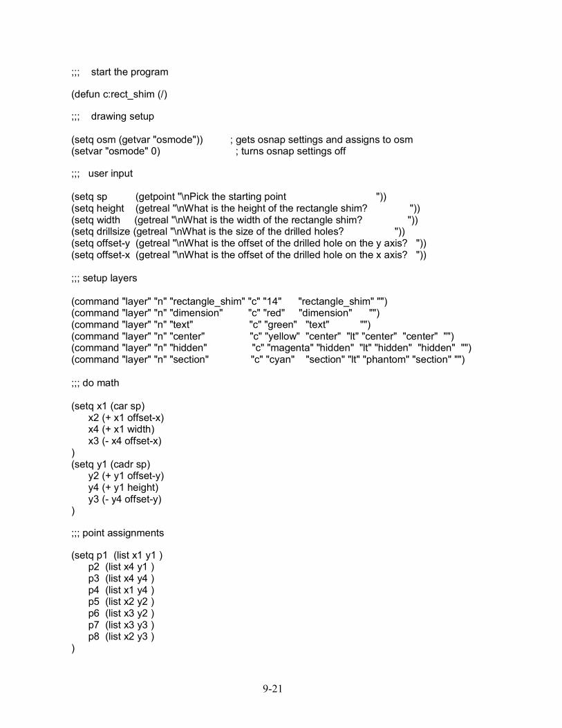
;;; start the program (defun c:rect_shim (/) ;;; drawing setup (setq osm (getvar "osmode")) ; gets osnap settings and assigns to osm (setvar "osmode" 0) ; turns osnap settings off ;;; user input (setq sp (getpoint "\nPick the starting point ")) (setq height (getreal "\nWhat is the height of the rectangle shim? ")) (setq width (getreal "\nWhat is the width of the rectangle shim? ")) (setq drillsize (getreal "\nWhat is the size of the drilled holes? ")) (setq offset-y (getreal "\nWhat is the offset of the drilled hole on the y axis? ")) (setq offset-x (getreal "\nWhat is the offset of the drilled hole on the x axis? ")) ;;; setup layers (command "layer" "n" "rectangle_shim" "c" "14" "rectangle_shim" "") (command "layer" "n" "dimension" "c" "red" "dimension" "") (command "layer" "n" "text" "c" "green" "text" "") (command "layer" "n" "center" "c" "yellow" "center" "lt" "center" "center" "") (command "layer" "n" "hidden" "c" "magenta" "hidden" "lt" "hidden" "hidden" "") (command "layer" "n" "section" "c" "cyan" "section" "lt" "phantom" "section" "") ;;; do math (setq x1 (car sp) x2 (+ x1 offset-x) x4 (+ x1 width) x3 (- x4 offset-x) ) (setq y1 (cadr sp) y2 (+ y1 offset-y) y4 (+ y1 height) y3 (- y4 offset-y) ) ;;; point assignments (setq p1 (list x1 y1 ) p2 (list x4 y1 ) p3 (list x4 y4 ) p4 (list x1 y4 ) p5 (list x2 y2 ) p6 (list x3 y2 ) p7 (list x3 y3 ) p8 (list x2 y3 ) )
9-22
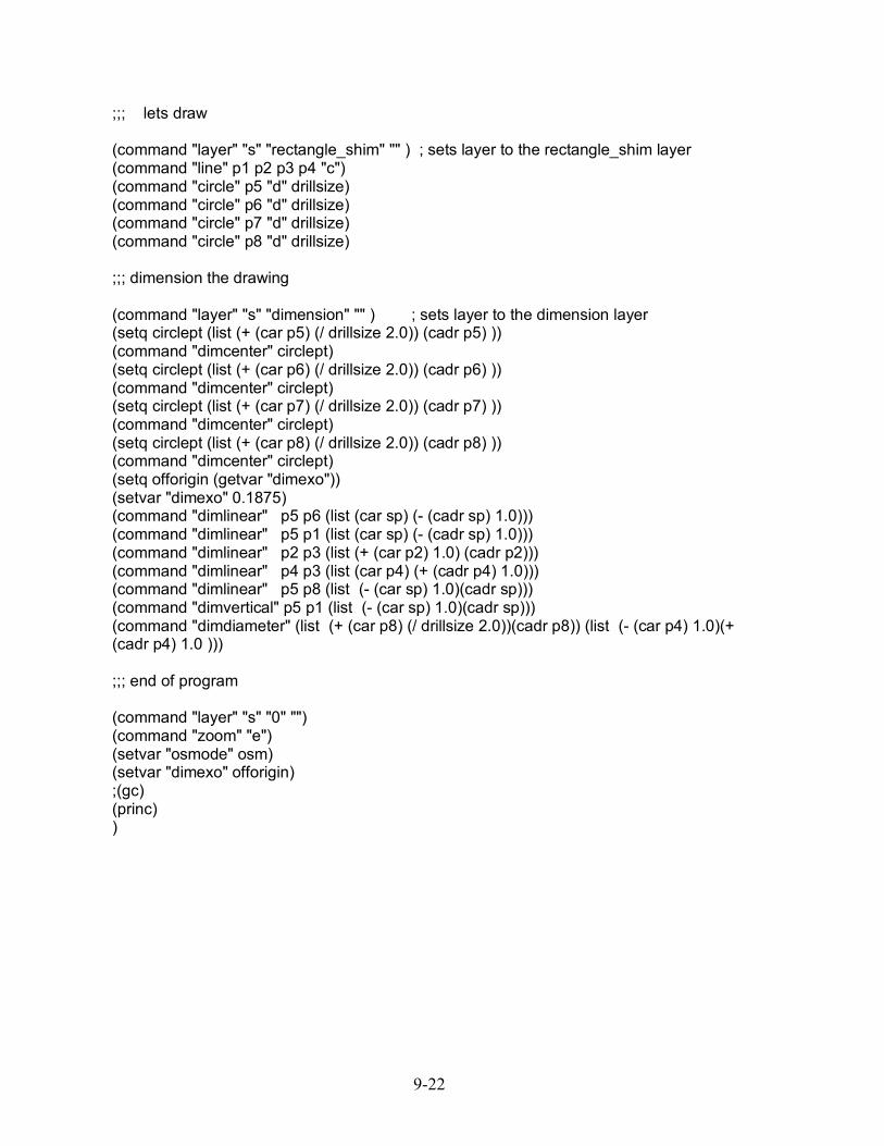
;;; lets draw (command "layer" "s" "rectangle_shim" "" ) ; sets layer to the rectangle_shim layer (command "line" p1 p2 p3 p4 "c") (command "circle" p5 "d" drillsize) (command "circle" p6 "d" drillsize) (command "circle" p7 "d" drillsize) (command "circle" p8 "d" drillsize) ;;; dimension the drawing (command "layer" "s" "dimension" "" ) ; sets layer to the dimension layer (setq circlept (list (+ (car p5) (/ drillsize 2.0)) (cadr p5) )) (command "dimcenter" circlept) (setq circlept (list (+ (car p6) (/ drillsize 2.0)) (cadr p6) )) (command "dimcenter" circlept) (setq circlept (list (+ (car p7) (/ drillsize 2.0)) (cadr p7) )) (command "dimcenter" circlept) (setq circlept (list (+ (car p8) (/ drillsize 2.0)) (cadr p8) )) (command "dimcenter" circlept) (setq offorigin (getvar "dimexo")) (setvar "dimexo" 0.1875) (command "dimlinear" p5 p6 (list (car sp) (- (cadr sp) 1.0))) (command "dimlinear" p5 p1 (list (car sp) (- (cadr sp) 1.0))) (command "dimlinear" p2 p3 (list (+ (car p2) 1.0) (cadr p2))) (command "dimlinear" p4 p3 (list (car p4) (+ (cadr p4) 1.0))) (command "dimlinear" p5 p8 (list (- (car sp) 1.0)(cadr sp))) (command "dimvertical" p5 p1 (list (- (car sp) 1.0)(cadr sp))) (command "dimdiameter" (list (+ (car p8) (/ drillsize 2.0))(cadr p8)) (list (- (car p4) 1.0)(+ (cadr p4) 1.0 ))) ;;; end of program (command "layer" "s" "0" "") (command "zoom" "e") (setvar "osmode" osm) (setvar "dimexo" offorigin) ;(gc) (princ) )

9-23