Australian Engineered Fasteners and Anchors Council AEFAC … · 2016-07-20 · Australian...
94
AEFAC Standard – Part 1: public consultation draft 15/4/2015 i Australian Engineered Fasteners and Anchors Council AEFAC STANDARD PART I DESIGN OF POST-INSTALLED AND CAST-IN FASTENINGS TO CONCRETE Public consultation draft Public comment opens: 15 th April, 2015 Public comment closes: 10 th June, 2015 All feedback is to be included in the AEFAC Standard Public Comment Template available for download at www.aefac.org.au/resources.php. Questions and feedback are to be submitted via email to David Heath, Chair of the AEFAC Standard Development Committee, [email protected].
Transcript of Australian Engineered Fasteners and Anchors Council AEFAC … · 2016-07-20 · Australian...
AEFAC Standard – Part 1: public consultation draft 15/4/2015 i
Australian Engineered
Fasteners and Anchors Council
AEFAC STANDARD PART I
DESIGN OF POST-INSTALLED AND CAST-IN FASTENINGS TO CONCRETE
Public consultation draft Public comment opens: 15th April, 2015 Public comment closes: 10th June, 2015 All feedback is to be included in the AEFAC Standard Public Comment Template available for download at www.aefac.org.au/resources.php.
Questions and feedback are to be submitted via email to David Heath, Chair of the AEFAC Standard Development Committee, [email protected].

AEFAC Standard – Part 1: public consultation draft 15/4/2015 ii
P R E F A C E
This Australian Engineered Fasteners and Anchors Council (AEFAC) Standard Part 1 was prepared by the AEFAC Standard Development Committee. This document was approved on XX/XX/2015.
This Design Guideline was published on XX/XX/2015 and is available at www.aefac.org.au.
The following are represented on the AEFAC Standard Development Committee:
Allthread Industries Pty Ltd Ancon Building Products Australian Building Codes Board Australian Engineered Fasteners and Anchors Council Australian Steel Institute Australian Window Association Commonwealth Scientific and Industrial Research Organisation (CSIRO) Concrete Institute of Australia Edith Cowan University Engineers Australia Hilti (Aust.) Housing Industry Association Ltd Hobson Engineering Company Pty Ltd ITW Construction Systems National Precast Concrete Association Australia Simpson Strong-Tie Stanley Black & Decker Australia Pty Ltd (Powers) Swinburne University of Technology Würth Australia Pty Ltd
This Standard has adopted the terms ‘normative’ and ‘informative’ for the appendix to which they apply. A ‘normative’ appendix is an integral part of the Standard, whereas an ‘informative’ appendix is provided for information and guidance.

AEFAC Standard – Part 1: public consultation draft 15/4/2015 iii
C O N T E N T S
Preface ........................................................................................................................................................... ii
1 Scope and General ................................................................................................................................. 1
1.1 Scope and application .................................................................................................................... 1
1.2 References ..................................................................................................................................... 2
1.3 Definitions ..................................................................................................................................... 2
1.4 Notation ......................................................................................................................................... 8
2 Materials and installation .................................................................................................................... 17
2.1 General ........................................................................................................................................ 17
2.2 Types of fasteners and fastening groups ...................................................................................... 17
2.3 Dimensions of fasteners .............................................................................................................. 17
2.4 Fastener materials ........................................................................................................................ 18
2.5 Concrete ....................................................................................................................................... 18
2.6 Reinforcement ............................................................................................................................. 18
2.7 Installation ................................................................................................................................... 18
3 General design requirements ............................................................................................................... 19
3.1 General ........................................................................................................................................ 19
3.2 Verifications for design ............................................................................................................... 19
3.3 Concrete condition ....................................................................................................................... 20
3.4 Report of Assessment .................................................................................................................. 21
3.5 Verification of fastener strength .................................................................................................. 21
4 Determination of forces acting on fasteners ........................................................................................ 30
4.1 General ........................................................................................................................................ 30
4.2 Headed fasteners and post-installed fasteners ............................................................................. 30
4.3 Anchor channel ............................................................................................................................ 35
4.4 Supplementary reinforcement...................................................................................................... 36
5 Detailing of supplementary reinforcement .......................................................................................... 38
6 Design for tensile loading .................................................................................................................... 40
6.1 General ........................................................................................................................................ 40
6.2 Post-installed fasteners and Cast-in headed fasteners ................................................................. 40
6.3 Cast-in anchor channel ................................................................................................................ 53
7 Design for shear loading ...................................................................................................................... 60
7.1 General ........................................................................................................................................ 60
7.2 Post-installed fasteners and Cast-in headed fasteners ................................................................. 60
AEFAC Standard – Part 1: public consultation draft 15/4/2015 iv
7.3 Cast-in anchor channel ................................................................................................................ 68
8 Design for combined tension and shear loading .................................................................................. 73
8.1 Steel failure .................................................................................................................................. 73
8.2 Failure modes other than steel ..................................................................................................... 74
8.3 Additional verification for fasteners with supplementary reinforcement .................................... 75
9 Design for serviceability ...................................................................................................................... 77
9.1 Verifications ................................................................................................................................ 77
9.2 Displacement ............................................................................................................................... 77
9.3 Limiting crack width ................................................................................................................... 77
10 Design for fatigue loading ............................................................................................................... 78
10.1 General ........................................................................................................................................ 78
10.2 Strength of fastener ...................................................................................................................... 78
11 References ....................................................................................................................................... 82
Appendix A (informative) Assumptions for the design and execution of fasteners .................................... 84
A.1 General ............................................................................................................................................. 84
A.2 Post-installed fasteners ..................................................................................................................... 84
A.3 Cast-in headed fasteners ................................................................................................................... 84
A.4 Anchor channel ................................................................................................................................. 85
Appendix B (informative) method of design for post-installed fasteners ................................................... 86
B.1 General .............................................................................................................................................. 86
B.2 Design method A .............................................................................................................................. 86
B.3 Design method B .............................................................................................................................. 87
B.4 Design method C .............................................................................................................................. 88
Appendix C (normative) Verification of resistance of concrete elements to loads applied by fasteners .... 89
C.1 General .............................................................................................................................................. 89
C.2 Lightly loaded applications ............................................................................................................... 89
AEFAC Standard – Part 1: public consultation draft 15/4/2015 1
1 S C O P E A N D G E N E R A L
1.1 SCOPE AND APPLICATION
1.1.1 Scope
This Standard provides the minimum requirements for the design of individual fasteners or fastener groups used to transmit loads to concrete.
The type of fasteners covered in this Standard are as follows –
a) Post-installed fasteners – (i) Mechanical anchors (e.g. expansion anchors, undercut anchors and concrete screws) (ii) Chemical anchors (e.g. bonded anchors, bonded expansion anchors)
b) Cast-in fasteners – (i) Headed fasteners (ii) Anchor channel with rigid connection (e.g. forged or welded) between the channel and
anchor
1.1.2 Application
This Standard is intended to apply to the design of safety-critical fasteners to concrete structures.
The design theory for fasteners embodied in this Standard utilises the tensile strength of concrete and is closely based on the design procedure published in prEN 1992-4 “Eurocode 2: Design of concrete structures – part 4: design of fastenings for use in concrete”.
This Standard relies upon design parameters and product specifications that are stated in the corresponding Report of Assessment (refer to AEFAC Standard Part 2).
Concrete members shall be composed of normal-weight concrete without fibres with further provisions provided in Clause 2.5.
Supplementary reinforcement and reinforcing steel inserts in bonded anchors shall have a ductility class type N in accordance with AS/NZS 4671.
1.1.3 Exclusions
This Standard is applicable to the design of permanent structures. It is not intended for the design of fasteners for use in applications pertaining to lifting, transport or erection of prefabricated concrete elements.
This Standard shall not be used for the design of fasteners that do not have a Report of Assessment.
This Standard does not apply to fasteners in redundant non-structural systems whereby excessive slip of failure of a fastener will result in the load being transmitted to neighbouring fasteners without violating the serviceability and ultimate limit state requirements of the fixture.
This Standard does not apply to other types of fasteners such as lifting inserts, brace inserts, ferrules, post-installed reinforcing bars, headed reinforcement or anchorage for prestressing strands.
The design provisions in this Standard for anchor channels do not apply to the following –
AEFAC Standard – Part 1: public consultation draft 15/4/2015 2
i) Shear in the longitudinal direction of anchor channel. ii) Fatigue loading
This Standard does not cover the design of fixtures.
1.1.4 Loading on fasteners
The design provisions in this Standard are relevant to static, quasi-static and fatigue loading and may include tension, shear, bending or torsion moments, or a combination thereof.
A fastener shall have a nominal prequalification for static loading and shall receive explicit prequalification for fatigue loading as noted in the Report of Assessment in order to be eligible for use in fatigue applications.
The mechanism for transfer of axial compression shall be either direct bearing of the bottom plate of the fixing on the concrete, or via fasteners specifically suitable for the transfer of compression.
1.1.4.1 Exposure to fire
This Standard does not address the design of fasteners for exposure to fire. The fasteners shall be designed for exposure to fire in accordance with fire engineering principles.
1.1.4.2 Durability
This Standard does not cover design for durability.
Note: It is assumed that the fastener possesses the necessary durability performance throughout its intended service life without the need for undue maintenance.
1.1.4.3 Seismic design
This Standard does not cover design for seismic actions.
Note: Guidelines for the design of fasteners to seismic actions may be found in prEN 1992-4:2013 that is applicable to fasteners that have been prequalified for use in seismic applications in accordance with ETAG 001 Annex E.
1.2 REFERENCES
A list of normative and informative references is included in Section 11.
1.3 DEFINITIONS
1.3.1 General
For the purpose of this Standard, the definitions below apply.
1.3.2 Administrative definitions
1.3.2.1 Report of Assessment
A product appraisal that is based on rigorous testing and assessment of safety-critical fasteners which provides the design parameters and product specification necessary for use with this Standard. The Report
AEFAC Standard – Part 1: public consultation draft 15/4/2015 3
of Assessment shall comply with the requirements of AEFAC Standard Part 2. Fasteners with a current European Technical Assessment/Approval (ETA) satisfy the requirements of the Report of Assessment.
1.3.3 Technical definitions
1.3.3.1 Anchor
A type of fastener made from steel or malleable iron to be cast into or post-installed into hardened concrete. The function of the anchor is to transmit load from a fixture to the connected concrete member.
1.3.3.2 Anchor channel
A profiled steel element with integrated anchors that is installed in position prior to the casting of concrete.
1.3.3.3 Anchor group
Two or more anchors having the same characteristics whose spacing does not exceed the anchor’s characteristic spacing and act to support the same attachment.
1.3.3.4 Anchor spacing
The distance between the centre lines of two anchors.
1.3.3.5 Base material
The material in which the fastener is installed.
1.3.3.6 Blow-out failure
A mode of failure that is characterised by spalling of the side face of the concrete member that is confined to a region adjacent to the head of the fastener. This failure mode does not involve concrete break-out at the top surface of the concrete member.
1.3.3.7 Bond failure
A mode of failure for chemical anchors that is characterised by pull-out of the fastener caused by either separation at the interface of the bonding compound and the embedded steel element or between the bonding compound and the base material.
1.3.3.8 Capacity reduction factor
A factor used to multiply the nominal capacity to obtain the design capacity.
1.3.3.9 Cast-in fastener
A fastener that is installed into position prior to the casting of concrete (refer to Figure 2).
1.3.3.10 Channel bolt
A screw or bolt positioned in the steel profile of the anchor channel that is used to connect an element to the anchor channel.

AEFAC Standard – Part 1: public consultation draft 15/4/2015 4
1.3.3.11 Characteristic edge distance
The distance required between the free edge of a concrete member and the centreline axis of the fastener in order to develop the characteristic strength of the fastener.
1.3.3.12 Characteristic spacing
The distance required between two fasteners with the same characteristics in order for the characteristic strength of the fastener to be achieved.
1.3.3.13 Characteristic strength
The 5% fractile (value with a 95% probability of being exceeded with a confidence of 90%).
1.3.3.14 Chemical anchor
A post-installed fastener that includes a steel element (threaded rod or reinforcing bar) and a bonding compound that transmits loads from the embedded steel element into the base material.
1.3.3.15 Chemical expansion anchor
A chemical anchor with an embedded steel element with a profile specially designed such that the application of displacement on it results in follow-up expansion.
1.3.3.16 Combined pull-out and concrete cone failure
A mode of failure possible for chemical anchors that is characterised by bond failure in the lower portion of the embedded fastener and concrete cone failure in the upper portion of the embedded fastener.
1.3.3.17 Concrete cone failure
A mode of failure that is characterised by the formation of a cone or wedge of concrete surrounding a fastener or group of fasteners that become separated from the base material.
1.3.3.18 Concrete pry-out failure
A mode of failure that is characterised by the formation of a concrete spall on the opposing side of the fastener relative to the direction of shear loading.
1.3.3.19 Concrete screw
A post-installed fastener installed into a pre-drilled hole that contains threads to engage with the substrate via mechanical interlock.
1.3.3.20 Deformation-controlled expansion anchor
A post-installed fastener installed into a pre-drilled hole that requires an internal plug in the sleeve to be driven via a hammer during the setting procedure of installation, resulting in lateral expansion of the fastener. A follow-up expansion behaviour does not exist.
Note: Also known as ‘drop-in’ anchor or ‘knock-in’ anchor.
AEFAC Standard – Part 1: public consultation draft 15/4/2015 5
1.3.3.21 Edge distance
The distance between the free edge of the concrete member and the centreline axis of the fastener.
1.3.3.22 Effective embedment depth
The length of the fastener that is considered to effectively engage the base material. This is generally smaller than the total length of the fastener that is embedded (refer to Figure 3 and Figure 4).
1.3.3.23 Fastener
See anchor.
1.3.3.24 Fastener group
See anchor group.
1.3.3.25 Fixture
The element that is being secured to the base material via fasteners.
1.3.3.26 Headed fastener
A cast-in fastener that derives its tensile strength via mechanical interlock between its head and the base material.
1.3.3.27 Mechanical interlock
A mechanism of load transfer involving the bearing of a surface of the fastener against a surface of the base material.
1.3.3.28 Minimum edge distance
The minimum distance required between the free edge of the concrete member and the centreline axis of the fastener to facilitate adequate placing and compaction of concrete for cast-in fasteners and to avoid damage during installation of post-installed fasteners. This is product dependent and is specified in the Report of Assessment.
1.3.3.29 Minimum member thickness
The minimum thickness of the concrete member in which a fastener may be installed. This is product dependent and is specified in the Report of Assessment.
1.3.3.30 Minimum spacing
The minimum distance required between the centreline of two fasteners to facilitate adequate placing and compaction of concrete for cast-in fasteners and to avoid damage to the concrete during installation of post-installed fasteners. This is product dependent and is specified in the Report of Assessment.
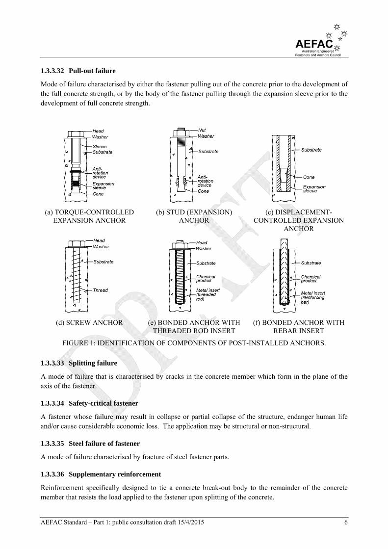
1.3.3.31 Post-installed fastener
A fastener that is installed in concrete in the hardened state (refer to Figure 1).
AEFAC Standard – Part 1: public consultation draft 15/4/2015 6
1.3.3.32 Pull-out failure
Mode of failure characterised by either the fastener pulling out of the concrete prior to the development of the full concrete strength, or by the body of the fastener pulling through the expansion sleeve prior to the development of full concrete strength.
(a) TORQUE-CONTROLLED EXPANSION ANCHOR
(b) STUD (EXPANSION) ANCHOR
(c) DISPLACEMENT-CONTROLLED EXPANSION
ANCHOR
(d) SCREW ANCHOR (e) BONDED ANCHOR WITH THREADED ROD INSERT
(f) BONDED ANCHOR WITH REBAR INSERT
FIGURE 1: IDENTIFICATION OF COMPONENTS OF POST-INSTALLED ANCHORS.
1.3.3.33 Splitting failure
A mode of failure that is characterised by cracks in the concrete member which form in the plane of the axis of the fastener.
1.3.3.34 Safety-critical fastener
A fastener whose failure may result in collapse or partial collapse of the structure, endanger human life and/or cause considerable economic loss. The application may be structural or non-structural.
1.3.3.35 Steel failure of fastener
A mode of failure characterised by fracture of steel fastener parts.
1.3.3.36 Supplementary reinforcement
Reinforcement specifically designed to tie a concrete break-out body to the remainder of the concrete member that resists the load applied to the fastener upon splitting of the concrete.

AEFAC Standard – Part 1: public consultation draft 15/4/2015 7
1.3.3.37 Torque-controlled expansion anchor
A post-installed fastener installed into a pre-drilled hole that develops its tensile strength via friction between its sleeves that expand laterally against the hole wall due to a wedge being drawn up behind the sleeves. The lateral expansion occurs due to the application of torque to the fastener during installation. Follow-up expansion may occur due to the application of tensile load.
1.3.3.38 Undercut anchor
A type of post-installed fastener that derives its tensile strength via mechanical interlock between its head and an undercut region in the base material at the head of the fastener that is achieved via a special drill or by the fastener during installation.
FIGURE 2: IDENTIFICATION OF COMPONENTS OF AN ANCHOR CHANNEL.
(a) HEADED FASTENER
(b) HEADED FASTENER WITH LARGE ANCHOR PLATE IN AT LEAST ONE DIRECTION,
b1 > 0.5hn or t > 0.2hn
(c) HEADED FASTENER WITH SMALL ANCHOR
PLATE IN BOTH DIRECTIONS SUCH THAT b1
< 0.5hn AND t < 0.2hn
FIGURE 3: IDENTIFICATION OF EFFECTIVE EMBEDMENT DEPTH, hef FOR CAST-IN HEADED FASTENERS.

AEFAC Standard – Part 1: public consultation draft 15/4/2015 8
FIGURE 4: IDENTIFICATION OF EFFECTIVE EMBEDMENT DEPTH, hef FOR POST-INSTALLED MECHANICAL AND CHEMICAL ANCHORS.
1.4 NOTATION
The symbols used in this Standard are listed below.
Unless specified otherwise, nominal units for length are millimetres (mm) and nominal units for material strength are megapascals (MPa).
Ac,N = actual projected area of the failure cone of the fastener that is limited by adjacent fasteners and edges of the concrete member under tensile loading
Ac,Nb = reference projected area of concrete cone failure of a fastener under tensile loading
Ac,V = actual area of idealised concrete break-out body of a fastener under shear loading
Ah = area of the load-bearing head of a fastener
Ap,N = actual bond influence area of a single chemical fastener
As = stress cross-sectional area of the fastener
A0c,N = reference projected area of the failure cone of the fastener under tensile loading
A0c,Nb = reference projected area of a single fastener for blow-out failure
A0c,V = reference projected area of the break-out body of a fastener under shear loading
A0p,N = reference bond influence area of a single chemical fastener for combined pull-out failure
and concrete cone failure
a = spacing between the outermost fasteners of adjacent fastener groups or between the outermost fasteners and an individual fastener
a3 = distance between the assumed point of restraint of the fastener loaded in shear and the surface of the concrete
bch = width of the anchor channel
c = edge distance from the centreline axis of a fastener or centreline axis of anchor channel (refer to Figure 5)
ccr,N = edge distance of a single fastener required to ensure the characteristic strength of the fastener is achieved when loaded in tension
ccr,Np = edge distance of a single fastener required to ensure the characteristic strength of the fastener is achieved for a bonded fastener under tensile loading

AEFAC Standard – Part 1: public consultation draft 15/4/2015 9
ccr,sp = characteristic edge distance in the case of splitting under load
ccr,V = edge distance of a single fastener required to ensure the characteristic strength of the fastener is achieved when loaded in shear
cmax = maximum edge distance to the fastener
cmin = minimum edge distance to the fastener
c1 = edge distance in direction 1
c2 = edge distance in direction 2
c2,max = largest of two edge distances parallel to the direction of loading
c’cr,Np = modified characteristic edge distance of a chemical fastener for combined pull-out and concrete cone failure
d = diameter of fastener bolt or thread diameter, or diameter of the stud or shank of a headed stud
da = diameter of an anchor in an anchor channel
db = nominal diameter of a reinforcing bar
df = diameter of the clearance hole in the fixture
dh = diameter of the head of the fastener
dnom = outside diameter of the fastener
Es = modulus of elasticity of steel
e = eccentricity of applied load
eN = eccentricity of the resultant tension force acting on a group of fasteners relative to the centre of gravity of the fasteners loaded in tension
es = distance between the centreline of supplementary reinforcement and the line of action of the design shear force
eV = eccentricity of the resultant shear force acting on a group of fasteners relative to the centre of gravity of the fasteners loaded in shear
FRk = characteristic strength of fastener
F0Rk = single value representing the basic characteristic strength of a fastener designed according
to Method B
f = distance between the head of the fastener and the upper or lower surface of the concrete member
fsy = characteristic yield strength of reinforcement (referred to as Re in AS/NZS 4671)
fyf = yield tensile strength of fastener
fuf = ultimate tensile strength of fastener
f'c = characteristic compressive strength of concrete measured via cylinder tests at 28 days
f’ct = characteristic uniaxial flexural tensile strength of concrete
AEFAC Standard – Part 1: public consultation draft 15/4/2015 10
h = concrete member depth in which the fastener is installed
hch = height of anchor channel
hcr,V = characteristic member thickness for a fastener loaded in shear
hef = effective embedment depth of a fastener
hmin = minimum concrete member depth (published in the Report of Assessment)
hn = total embedment depth of headed fastener beneath anchor plate to which it is welded
h’ef = modified effective embedment depth
Iy = moment of inertia of channel relative to the y-axis of the channel
kcr,N = parameter relating to cracked concrete loaded in tension
kucr,N = parameter relating to uncracked concrete loaded in tension
k = parameter
kcr,V = parameter related to cracked concrete loaded in shear
kucr,V = parameter for uncracked concrete loaded in shear
Lst = development length of a bar for a tensile stress less than the yield stress
la = length of lever arm of fastener loaded in shear
lf = parameter related to the length of the fastener
MRk,s = characteristic flexural strength
MRk,s,flex = characteristic flexural strength of an anchor channel
M0Rk,s = reference characteristic flexural strength of a fastener
M* = design bending moment
Mch* = design bending moment experienced by anchor channel due to the application of design tensile load, Nch*
n = number of fasteners in a group
Nfat = fatigue tensile load acting on the fastener
Nhfat = fatigue tensile load acting on the most loaded fastener in a group
Ngfat = resultant fatigue tensile load acting on a fastener group
Ni = tension force applied to a fastener that influences the performance of the fastener under consideration
No = tension force in the fastener under consideration
NRk,c = characteristic tensile strength of a fastener to concrete cone failure
NRk,cb = characteristic tensile strength of a fastener to blow-out failure
NRk,i = characteristic tensile strength of a fastener or group to failure mode ‘i’
NRk,p = characteristic tensile strength of a fastener to pull-out failure

AEFAC Standard – Part 1: public consultation draft 15/4/2015 11
NRk,s = characteristic tensile strength of a fastener to steel failure
NRk,sp = characteristic tensile strength of a fastener to splitting failure
NRk,s,a = characteristic tensile strength of a fastener in anchor channel against steel fracture
NRk,s,c = characteristic tensile strength of a fastener in anchor channel against failure of the connection between the anchor and channel
NRk,i = characteristic tensile strength of a fastener to failure mode ‘i’
NRk,s,l = characteristic tensile strength of a fastener in anchor channel against local failure by flexure of the channel lips
N0Rk = reference characteristic tensile strength of a fastener
N0Rk,c = reference characteristic tensile strength of a fastener to concrete cone failure
N0Rk,cb = reference characteristic tensile strength of a fastener to blow-out failure
N0Rk,p = reference characteristic tensile strength of a fastener to pull-out failure
N0Rk,sp = reference characteristic tensile strength of a fastener to splitting failure
N* = design tensile load applied to a fastener or group of fasteners
Na* = design tensile load acting on an individual anchor in the anchor channel
Nc* = design compressive force
Ncb* = design tensile load acting on one channel bolt in the anchor channel
Nch* = design tensile load applied to anchor channel
Nh* = design tensile load acting on a fastener group
Nh,re* = design tensile force resisted by supplementary reinforcement
Nre* = design tensile force in the supplementary reinforcement
n = number of fasteners
nch = number of fasteners in an anchor channel within a distance equal to the characteristic spacing of the fastener under consideration
Ru = nominal capacity of the fastener
S* = design action effect resulting from the ultimate limit state design loads
s = distance (spacing) between two fasteners (refer to Figure 5)
scbo = actual spacing of anchor channel bolts
scrit = critical spacing under shear loading caused by a torsion moment applied to a fixture secured by the fasteners
scr,N = spacing that is required for a fastener to develop its characteristic tensile strength
scr,Nb = spacing that is required for a fastener to develop its characteristic tensile strength against blow-out failure
scr,Np = spacing that is required for a fastener to develop its characteristic tensile strength against

AEFAC Standard – Part 1: public consultation draft 15/4/2015 12
pull-out failure
scr,V = spacing that is required for a fastener to develop its characteristic shear strength against concrete edge failure
si = distance between fastener under consideration and neighbouring fastener
sl,v = characteristic spacing of anchors for channel lip failure under shear loading
smax = maximum centre-to-centre spacing of fasteners
smin = minimum centre-to-centre spacing of fasteners
s’cr,Np = modified spacing that is required for a fastener to develop its characteristic tensile strength against pull-out failure
T* = design torque applied to fixture
t = thickness of anchor plate
tfix = thickness of fixture in contact with the fastener
tgrout = thickness of a layer of grout
th = thickness of the head of a headed fastener
Vfat = fatigue shear load acting on the fastener
Vhfat = fatigue shear load acting on the most loaded fastener in a group
Vgfat = resultant fatigue shear load acting on a fastener group
Vi = shear force applied to a fastener that influences the performance of the fastener under consideration
Vo = shear force in the fastener under consideration
VRk,c = characteristic shear strength of a fastener to concrete edge failure
VRk,cp = characteristic shear strength of a fastener to pry-out failure
VRk,i = characteristic shear strength of a fastener to failure mode ‘i’
VRk,s = characteristic shear strength of a fastener to steel failure
VRk,s,a = characteristic shear strength of anchor against steel fracture
VRk,s,c = characteristic shear strength of anchor channel against failure of the connection between anchor and channel
VRk,s,l = characteristic shear strength of anchor channel to flexural failure of channel lip
VRk,s,M = characteristic shear strength of a fastener to steel failure when a grout layer of limited thickness is present
Vu = shear capacity of concrete element determined in accordance with AS 3600
V0Rk,c = reference characteristic shear strength of a fastener to concrete edge failure
V0Rk,s = reference characteristic shear strength of a fastener to steel failure
V0Rk,s,m = reference characteristic shear strength of a fastener accounting for ductility
AEFAC Standard – Part 1: public consultation draft 15/4/2015 13
V* = design shear load applied to a fastener or group of fasteners
Va* = design shear load acting on one anchor in anchor channel
Vcb* = design shear load acting on one channel bolt in the anchor channel
Vh* = design shear load acting on the most loaded fastener in a group
Vg* = design shear load acting on a fastener group
wk = width of concrete crack
z = internal lever arm
α = parameter
αsus = ratio of sustained loads (permanent actions and permanent component of variable actions) to the total value of actions acting on the fastener at ultimate limit state
αM = parameter accounting for the degree of restraint of a lever arm
αV = angle between the applied load and the direction perpendicular to the free edge under consideration
β = parameter
βN,fat = parameter representing the ratio of design fatigue action to design fatigue strength for tensile loading
βV,fat = parameter representing the ratio of design fatigue action to design fatigue strength for shear loading
χind = load factor for indirect actions
χF,fat = load factor for fatigue loading
δd = permissible displacement of fastener for serviceability limit state
ϕ = capacity reduction factor
ϕc = capacity reduction factor for concrete
ϕi = capacity reduction factor for strength of fastener or fastener group for failure mode ‘i’
ϕinst = capacity reduction factor for installation
ϕMc = capacity reduction factor for concrete break-out failure, edge break-out failure, blow-out failure and pry-out failure
ϕMcb = capacity reduction factor for concrete blow-out failure
ϕMc,fat = capacity reduction factor for a concrete mode of failure under fatigue loading
ϕMp = capacity reduction factor for pull-out failure
ϕM,fat = capacity reduction factor for a material under fatigue loading
ϕMc,fat = capacity reduction factor for a concrete mode of failure
ϕMp,fat = capacity reduction factor for a pull-out mode of failure
ϕMs = capacity reduction factor for steel failure

AEFAC Standard – Part 1: public consultation draft 15/4/2015 14
ϕMsp = capacity reduction factor for concrete splitting failure
ϕMs,ca = capacity reduction factor for the connection between anchor and channel in tension and shear
ϕMs,fat = capacity reduction factor for steel failure mode under fatigue loading
ϕMs,flex = capacity reduction factor for steel failure of anchor channel in flexure
ϕMsp,fat = capacity reduction factor for a splitting mode of failure under fatigue loading
ϕMs,l = capacity reduction factor for local failure of anchor channel by bending of lips in tension and shear
ϕMs,N,fat = capacity reduction factor for steel failure under tensile loading
ϕMs,V,fat = capacity reduction factor for steel failure under shear loading
ϕMs,re = capacity reduction factor for tensile failure of supplementary reinforcement
ϕs.l = capacity reduction factor for steel failure of anchor channel
ψch,c,N = parameter accounting for the influence of a corner on the tensile strength of a fastener to concrete cone failure
ψch,c,Nb = parameter accounting for the influence of a corner on the tensile strength of a fastener to blow-out failure
ψch,c,V = parameter accounting for the influence of a corner on the shear strength of a fastener to concrete edge failure
ψch,e,N = parameter accounting for the influence of an edge of the concrete member on the concrete cone strength
ψch,h,Nb = parameter accounting for the influence of thickness of the concrete member on the tensile strength of the fastener to blow-out failure
ψch,h,V = parameter accounting for the influence of member thickness on the shear strength of the fastener to concrete edge failure
ψch,s,N = parameter accounting for the influence of neighbouring fasteners on the tensile strength of the fastener
ψch,s,Nb = parameter accounting for the influence of neighbouring fasteners on the characteristic tensile strength of the fastener to blow-out failure
ψch,s,V = parameter accounting for the disturbance to the distribution of stresses in the concrete on the shear strength of the fastener
ψch,90o
,V = parameter accounting for the influence of shear loads acting parallel to the free edge of the concrete member
ψec,N = parameter accounting for the influence of eccentricity of the resultant load in a fastener group on tensile strength
ψec,Nb = parameter accounting for the influence of eccentricity of loading on the blow-out strength of a fastener group
ψec,Np = Parameter accounting for eccentricity of loading on a fastener group for pull-out failure
AEFAC Standard – Part 1: public consultation draft 15/4/2015 15
ψec,V = parameter accounting for the influence on shear strength of the eccentricity of the resultant load acting on a fastener group
ψF,N = reduction factor applied to the tensile strength to account for the uneven distribution of the loads, provided in the Report of Assessment
ψF,V = reduction factor applied to the shear strength to account for the uneven distribution of loads, provided in the Report of Assessment
ψg,Nb = parameter accounting for the influence of a group effect on the tensile strength of a fastener to blow-out failure
ψg,Np = parameter accounting for the influence of a group effect on the tensile strength of a fastener to pull-out failure
ψh,sp = parameter accounting for the influence of concrete member thickness on the splitting strength of a fastener under tensile loading
ψh,V = parameter accounting for the influence of concrete member thickness on the shear strength of a fastener
ψM,N = parameter accounting for the influence of a compression force between the fixture and concrete on the tensile strength of a fastener
ψre,N = parameter accounting for the shell spalling effect
ψre,V = parameter accounting for the shell spalling effect
ψsus = factor accounting for the effects of sustained loading on bond strength
ψs,N = parameter accounting for the influence on tensile strength of a fastener of the disturbance to the distribution of stresses in the concrete due to the proximity of a fastener to an edge of the concrete member
ψs,Nb = parameter accounting for the influence on shear strength of a fastener to blow-out failure, of the disturbance to the distribution of stresses in the concrete due to the proximity of a fastener to an edge of the concrete member
ψs,Np = parameter accounting for the influence on tensile strength of a fastener to pull-out failure, of the disturbance to the distribution of stresses in the concrete due to the proximity of a fastener to an edge of the concrete member
ψs,V = parameter accounting for the influence on shear strength of a fastener of the disturbance to the distribution of stresses in the concrete due to the proximity of a fastener to an edge of the concrete member
ψ0g,Np = parameter accounting for the influence of a group effect on the tensile strength of a
fastener to pull-out failure
ψ0sus = product dependent factor accounting for the effects of sustained loading on bond strength
taken from the Report of Assessment
ψα,V = parameter accounting for the influence of the angle of the applied load on the shear strength of a fastener
σL = stresses experienced in the concrete due to external loads including those applied to the

AEFAC Standard – Part 1: public consultation draft 15/4/2015 16
fastener
σst = tensile stress in reinforcement
σR = stresses induced in the concrete due to the restraint of intrinsic loads plus stresses due to extrinsic imposed deformation
τRk = characteristic bond strength
τRk,c = characteristic bond strength for assessing the spacing of chemical fasteners
τRk,cr = characteristic bond strength for cracked concrete
τRk,ucr = characteristic bond strength uncracked concrete
(A) APPLICATION OF TENSILE LOAD TO FASTENINGS
(B) APPLICATION OF SHEAR LOAD TO FASTENINGS.
FIGURE 5: DEFINITION OF SPACING AND EDGE DISTANCE FOR FIXTURES CONTAINING FASTENINGS TO CONCRETE.

AEFAC Standard – Part 1: public consultation draft 15/4/2015 17
2 M A T E R I A L S A N D I N S T A L L A T I O N
2.1 GENERAL 2.2 TYPES OF FASTENERS AND FASTENING GROUPS
This Standard is applicable to the design of individual fasteners and fastener groups. All fasteners in a group shall be of the same type, size and depth. The transfer of load to fasteners in a group occurs via the fixture.
Design parameters such as material strength and product dimensions, and suitable applications for the fastener are given in the Report of Assessment.
This Standard is limited to the configuration of fasteners shown in Figure 6 with the following conditions:
i) Without hole clearance, all edge distances, all load directions ii) With limited hole clearance, no edge effects (ci > max(10hef, 60dnom)), all load directions iii) With limited hole clearance, close to an edge (ci < max(10hef, 60dnom)), tension-only loads
In addition to the configurations listed above, this Standard also covers configurations illustrated in Figure 7 that have limited hole clearance, are close to an edge (ci < max(10hef, 60dnom)), and include loading in all directions.
(i)
(iii)
(iv)
(v)
(vi)
(vii)
(ii)
FIGURE 6: CONFIGURATIONS OF FASTENINGS REMOTE FROM EDGES.
FIGURE 7: CONFIGURATIONS OF FASTENINGS CLOSE TO AN EDGE.
2.3 DIMENSIONS OF FASTENERS
This Standard is limited to design provisions for fasteners with a minimum diameter or minimum thread size equal to 6 mm (M6) or a corresponding cross-section. The effective embedment depth of a fastener, hef shall be taken from the Report of Assessment and shall in general, have a minimum value of hef > 40 mm. The effective embedment depth of chemical fasteners shall be limited to hef < 20dnom.

AEFAC Standard – Part 1: public consultation draft 15/4/2015 18
2.4 FASTENER MATERIALS
This Standard is limited to design provisions for fasteners that have a tensile strength limited to fu < 1000 MPa, with the exception of concrete screws which do not have a limit.
Metal fasteners covered in this Standard include the following:
i) Carbon steel (ISO 898, AS/NZS 4291.1, AS/NZS 4671) ii) Stainless steel (ISO 4506, AS/NZS 4671) iii) Malleable cast iron (ISO 5922).
2.5 CONCRETE
Concrete members shall exhibit a characteristic compressive strength at 28 days (f’c) in the range of 12 MPa to 90 MPa, with either the strength grade determined in accordance with AS 1379, or the compressive strength determined statistically from compressive strength tests in accordance with AS 1012.9. The strength grade(s) of concrete that a fastener may be used in shall be taken from the Report of Assessment.
The characteristic compressive strength (f’c) for design purposes shall not exceed 60 MPa.
The range of concrete strength design parameters for a given fastener design shall be provided in the corresponding Report of Assessment.
The density of normal-weight concrete shall be taken as 2400 kg/m3.
2.6 REINFORCEMENT
Where the fastening design includes supplementary reinforcement to resist loads, the reinforcement steel shall comply with the requirements of AS/NZS 4671.
2.7 INSTALLATION
The performance of fasteners is significantly influenced by the quality of installation. Appendix A provides a list of assumptions related to the design and execution of fasteners that should be followed to ensure that the fastener performs as intended.
This Standard does not cover gross errors such as incorrect diameter drill bit, incorrect drilling system, incorrect setting tools, no hole cleaning, incorrect technique for fastener placement and poor alignment.

AEFAC Standard – Part 1: public consultation draft 15/4/2015 19
3 G E N E R A L D E S I G N R E Q U I R E M E N T S
3.1 GENERAL
Safety-critical post-installed and cast-in fasteners for use in concrete shall be designed for ultimate limit state and serviceability limit state in accordance with the requirements of AS/NZS 1170.0 and the requirements of Sections 6, 7 and 8 (strength requirements) and Section 9 (serviceability requirements).
An alternative simplified design procedure for post-installed fasteners in Appendix B may be used instead of the provisions of Clauses 6.2 (tensile strength), 7.2 (shear strength), 8.1.1 and 8.2.1 (strength against combined tension and shear loading) that account for all loading directions and modes of failure.
Fasteners to be designed for fatigue loading shall comply with the requirements of this Standard and shall have prequalification for fatigue in the Report of Assessment.
The provisions of Appendix C shall be followed to ensure the safe transmission of loads from the fastener to the concrete member.
This Standard assumes minimum standards for the installation of fasteners and for the welding design of headed fasteners that should be followed. These provisions are included in Appendix A.
3.2 VERIFICATIONS FOR DESIGN
3.2.1 Strength limit state
The fastener shall be designed for the ultimate limit state to ensure that the design action effect (S*) does not exceed the design capacity (ϕRu) as follows –
S* < ϕRu (1)
where
S* = design action effect resulting from the ultimate limit state design loads determined in accordance with the requirements of AS/NZS 1170 and Section 4
ϕ = capacity reduction factor that shall not exceed a value included in Table 1.
Ru = nominal capacity of the fastener determined from Sections 6 to 8
3.2.2 Serviceability limit state
Design for the serviceability limit state shall limit deflections in accordance with Section 9 using information provided in the Report of Assessment.
Cracking in concrete shall be considered for applications involving supplementary reinforcement or an embedded base plate close to an edge.
3.2.3 Load factors
For the verification of indirect actions, a load factor of χind = 1.2 for concrete failure and χind = 1.0 for all other modes of failure shall be applied.
For the verification of fatigue actions, a load factor of χfat = 1.0 shall be applied for all modes of failure.

AEFAC Standard – Part 1: public consultation draft 15/4/2015 20
3.2.4 Capacity reduction factors
The capacity reduction factor for concrete including fastener sensitivity to installation, ϕMc is product dependent (refer to Table 1).
The capacity reduction factors for strength relating to static loading vary according to mode of failure and are found in Table 1.
The capacity reduction factor for the serviceability limit state, ϕM shall be taken as 1.0.
The capacity reduction factors for fatigue loading are included in Table 1.
3.3 CONCRETE CONDITION
The designer shall determine whether the concrete in the vicinity of the fastener is cracked or non-cracked. A non-cracked condition is such that no cracking of the concrete occurs along the entire embedment length of the fastener under the characteristic combination of loading at the serviceability limit state condition.
Note: It is conservative to assume that the concrete is cracked and the selection of a non-cracked condition should be justified by the designer via stress analysis.
A non-cracked condition is satisfied as follows –
σL + σR < f’ct (2)
where
σL = stresses experienced in the concrete due to external loads including those applied to the fastener, calculated assuming a non-cracked condition.
σR = stresses induced in the concrete due to the restraint of intrinsic loads (e.g. shrinkage) plus stresses due to extrinsic imposed deformation (e.g. temperature variation, movement of concrete support), calculated assuming a non-cracked condition. In the absence of a detailed analysis, σR = 3 MPa may be assumed.
f’ct = characteristic uniaxial flexural tensile strength of concrete calculated according to AS 3600, recommended to be taken as f’ct = 0.
For concrete members that transmit loads in two directions the above verification shall be performed for both directions.
Note: The project specification should typically include the following information – The strength grade of concrete adopted for design. Condition of the concrete, determined in accordance with Clause 3.3. Notification that the type, number, geometry and manufacturer of the fasteners should not be changed without the written consent of the responsible engineer. Notification that the fasteners shall be installed to the specified embedment depth. Construction drawings or supplementary design drawings including the following details – Type and number of fasteners Location of fasteners, including tolerances Edge distance and spacing of fasteners, including tolerances (normally only positive) Details of fixture including thickness and hole diameter (if applicable) Position of the attachment on the fixture, including tolerances Maximum thickness of mortar/grout between concrete and underside of fixture (if applicable) Special installation instructions (if applicable) that complement the manufacturer’s installation instructions. Reference to the manufacturer’s installation instructions. A note on site testing may be included for proof loading to verify correct installation.
AEFAC Standard – Part 1: public consultation draft 15/4/2015 21
3.4 REPORT OF ASSESSMENT
This Standard shall be used in combination with products that have a Report of Assessment that provides the design parameters of the fastener relating to its intended use. Full details of the Report of Assessment are included in AEFAC Standard Part 2.
A product with a current European Technical Assessment/Approval (ETA) satisfies the requirements of the Report of Assessment.
3.5 VERIFICATION OF FASTENER STRENGTH
The ultimate strength of the fastener shall be verified in accordance with Equation (1) by considering modes of failure under tensile loading (refer to Clause 3.5.1), modes of failure under shear loading (refer to Clause 3.5.2) and combined tension and shear loading (refer to Clause 3.5.3).
3.5.1 Tensile strength of fastener
3.5.1.1 Post-installed and cast-in headed fasteners
The design of post-installed fasteners and cast-in headed fasteners subjected to tensile loading shall be performed in accordance with the verifications listed in Table 2. The mode of failure producing the lowest design strength shall be decisive. Illustrations of each failure mode are provided in Figure 8.

AEFAC Standard – Part 1: public consultation draft 15/4/2015 22
TABLE 1: CAPACITY REDUCTION FACTORS FOR MODES OF FAILURE OF POST-INSTALLED AND CAST-IN FASTENERS.
Mode of failure Capacity reduction factor
Steel failure – fasteners
Tension
ϕMs
= 4.1165 ufyf ff
Shear – with and without lever arm = 8.0ufyf ff when fuf < 800 MPa and fyf/fyf < 0.8
= 2/3 when fuf > 800 MPa or fyf/fuf > 0.8
Steel failure – anchor channels
Tension – anchors and channel bolts
ϕMs
= 4.1/165 ufyf ff
Shear – with and without lever arm = 8.0ufyf ff when fuf < 800 MPa and fyf/fyf < 0.8
= 2/3 when fuf > 800 MPa or fyf/fuf > 0.8
Connection between anchor and channel in tension and shear
ϕMs,ca = 8.11
Local failure of channel lips by bending under tension and shear
ϕMs,l = 8.11
Flexural failure of anchor channel ϕMs,flex = 15.11
Steel failure – supplementary reinforcement
Tension ϕMs,re = 0.8
Concrete failure – tension
Concrete cone failure, concrete edge failure, blow-out failure, pry-out failure
ϕMc = ϕcϕinst
ϕc = 1/1.5 in general
ϕinst = 1.0 for headed fasteners and anchor channel in tension and shear that have been installed in accordance with Appendix A
< 1.0 for post-installed fasteners in tension, as per Report of Assessment
= 1.0 for post-installed fasteners in shear
Splitting failure ϕMsp = ϕMc
Pull-out failure
Pull-out failure, combined pull-out and concrete cone failure
ϕMp = ϕMc
Fatigue loading
Fatigue loading ϕMs,fat = 1/.35 for steel failure
ϕMc,fat = ϕMsp,fat = ϕMp,fat = ϕinst /1.5 (concrete cone failure, splitting failure and pull-out failure)

AEFAC Standard – Part 1: public consultation draft 15/4/2015 23
Note: The value for the capacity reduction factor is generally a fraction since the values are derived from partial safety factors from prEN 1992-4 and the accuracy has been maintained to avoid rounding errors.
TABLE 2: VERIFICATIONS REQUIRED FOR HEADED AND POST-INSTALLED FASTENERS LOADED IN TENSION.
Mode of failure
Reference
Single fastener
Fastener group
Figure Clause Most loaded
fastener Fastener group
Steel failure of fastener
Figure 8(a)
6.2.1 *N sRkMs N , *hN sRkMs N ,
Concrete cone failure
Figure 8(b)
6.2.2 *N cRkMc N , *gN cRkMc N ,
Pull-out failure of fastenera
Figure 8(c)
6.2.3 *N pRkMp N , *hN pRkMp N ,
Combined pull-out and concrete coneb
b
Figure 8(d)
6.2.4 *N pRkMp N , *gN pRkMp N ,
Splitting failure Figure
8(e) 6.2.5 *N spRkMsp N , *gN spRkMsp N ,
Blow-out failurec
Figure 8(f)
6.2.6 *N cbRkMcb N , *gN cbRkMcb N ,
Steel failure of reinforcement
Figure 8(g)
6.2.7 Design according to AS 3600
Anchorage failure of reinforcement
Figure 8(h)
6.2.7 Design according to AS 3600
a Not required for post-installed chemical fasteners b Not required for headed and post-installed mechanical fasteners c Exception see Clause 6.2.6.1.

AEFAC Standard – Part 1: public consultation draft 15/4/2015 24
(a) Steel (b) Concrete cone (c) Pull-out (d) Combined pull-out and concrete cone
(chemical fasteners)
(e) Splitting (f) Blow-out (g) Reinforcement - fracture (h) Reinforcement - anchorage
FIGURE 8: MODES OF FAILURE FOR POST-INSTALLED AND CAST-IN FASTENERS SUBJECTED TO TENSILE LOADING.
3.5.1.2 Cast-in anchor channel
The design of anchor channel subjected to tensile loading shall be performed in accordance with the verifications listed in Table 3. The mode of failure producing the lowest design strength shall be decisive. Illustrations of each failure mode are provided in Figure 9.

AEFAC Standard – Part 1: public consultation draft 15/4/2015 25
TABLE 3: VERIFICATIONS REQUIRED FOR ANCHOR CHANNEL LOADED IN TENSION.
Mode of failure
Reference
Channel
Most unfavourable anchor or channel bolt Figure Clause
Channel bolt fracture
Figure 9(a)
6.3.1 *N sRkMs N ,
Anchor fracture Figure 9(b)
6.3.1 *aN asRkMs N ,,
Connection between anchor and channel
Figure 9(c)
d *aN csRkcaMs N ,,,
Local flexure of channel lip
Figure 9(d)
d *N lsRklMs N ,,, b
Flexure of channel
Figure 9(e)
d *M flexsRkflexMs M ,,,
Concrete cone failure
Figure 9(f)
6.3.2 *aN cRkMc N , c
Pull-out failure Figure 9(g)
6.3.3 *aN pRkMp N ,
Splitting failure Figure 9(h)
6.3.4 *aN spRkMsp N , c
Blow-out failurea
Figure 9(i)
6.3.5 *aN cbRkMc N , c
Steel failure of supplementary reinforcement
Figure 9(j) 6.3.6 Design according to AS 3600
Anchorage failure of supplementary reinforcement
Figure 9(k) 6.3.6 Design according to AS 3600
a Not required for anchors with c > 0.5hef. b Most loaded anchor or channel bolt. c The most unfavourable anchor shall be determined on the basis of consideration of the load on the anchor
in conjunction with the edge distance and spacing. d Characteristic strength found in Report of Assessment

AEFAC Standard – Part 1: public consultation draft 15/4/2015 26
(a) Steel – channel bolt (b) Steel - anchor (c) Steel - anchor-channel
connection
(d) Steel - local flexure of channel lip
(e) Steel - flexure of channel
(f) Concrete cone (g) Pull-out (h) Splitting
(i) Blow-out (j) Supplementary reinforcement - fracture
(k) Supplementary reinforcement - anchorage
FIGURE 9: MODES OF FAILURE FOR ANCHOR CHANNEL SUBJECTED TO TENSILE LOADING.
3.5.2 Shear strength of fastener
3.5.2.1 Post-installed and cast-in headed fasteners
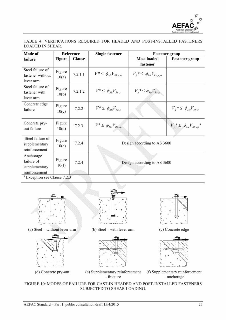
The design of post-installed fasteners and cast-in headed fasteners subjected to shear loading shall be performed in accordance with the verifications listed in Table 4. The mode of failure producing the lowest design strength shall be decisive. Illustrations of each failure mode are provided in Figure 10.
AEFAC Standard – Part 1: public consultation draft 15/4/2015 27
TABLE 4: VERIFICATIONS REQUIRED FOR HEADED AND POST-INSTALLED FASTENERS LOADED IN SHEAR.
Mode of failure
Reference Single fastener Fastener group Figure Clause Most loaded
fastener Fastener group
Steel failure of fastener without lever arm
Figure 10(a)
7.2.1.1 *V msRkMsV ,, *hV msRkMsV ,,
Steel failure of fastener with lever arm
Figure 10(b)
7.2.1.2 *V sRkMsV , *hV sRkMsV ,
Concrete edge failure
Figure 10(c)
7.2.2 *V cRkMcV , *gV cRkMcV ,
Concrete pry-out failure
Figure 10(d)
7.2.3 *V cpRkMcV ,
*gV cpRkMcV , a
Steel failure of supplementary reinforcement
Figure 10(e)
7.2.4 Design according to AS 3600
Anchorage failure of supplementary reinforcement
Figure 10(f)
7.2.4 Design according to AS 3600
a Exception see Clause 7.2.3
(a) Steel – without lever arm (b) Steel – with lever arm (c) Concrete edge
(d) Concrete pry-out (e) Supplementary reinforcement - fracture
(f) Supplementary reinforcement – anchorage
FIGURE 10: MODES OF FAILURE FOR CAST-IN HEADED AND POST-INSTALLED FASTENERS SUBJECTED TO SHEAR LOADING.

AEFAC Standard – Part 1: public consultation draft 15/4/2015 28
3.5.2.2 Cast-in anchor channel
The design of anchor channel subjected to shear loading shall be performed in accordance with the verifications listed in Table 5. The mode of failure producing the lowest design strength shall be decisive. Illustrations of each failure mode are provided in Figure 11.
TABLE 5: VERIFICATIONS REQUIRED FOR ANCHOR CHANNEL LOADED IN SHEAR.
Mode of failure
Reference Channel Most unfavourable anchor or channel bolt Figure Clause
Channel bolt without lever arm
Figure 11(a)
7.3.1.1 *V sRkMsV ,
Channel bolt with lever arm
Figure 11(b)
7.3.1.1 *V sRkMsV ,
Anchor Figure 11(c)
7.3.1.1 *V asRkMsV ,,
Connection between anchor and channel
Figure 11(d)
7.3.1.1 *V csRkMsV ,,
Local flexure of channel lip
Figure 11(e)
7.3.1.2 *V lsRklMs V ,,, a
Concrete edge failure
Figure 11(g)
7.3.2 *aV cRkMcV , b
Pry-out failure Figure 11(f)
7.3.3 *aV cpRkMcV ,
Steel failure of supplementary reinforcement
Figure 11(h)
7.3.4 Design according to AS 3600
Anchorage failure of supplementary reinforcement
Figure 11(i)
7.3.4
Design according to AS 3600
a Verification for most loaded channel bolt. b The most unfavourable anchor shall be determined on the basis of consideration of the load on the anchor in conjunction with the edge distance and spacing.

AEFAC Standard – Part 1: public consultation draft 15/4/2015 29
(a) Steel – channel bolt without lever
arm
(b) Steel – channel bolt with lever arm
(c) Steel - anchor (d) Steel – anchor/channel
connection
(e) Steel – flexure of channel lip
(f) Concrete edge (g) Pry-out (h) Supplementary reinforcement – fracture
(i) Supplementary reinforcement - anchorage
FIGURE 11: MODES OF FAILURE FOR ANCHOR CHANNEL SUBJECTED TO SHEAR LOADING.
3.5.3 Combined tension and shear strength of fastener
Verification of strength of post-installed fasteners and cast-in headed fasteners under combined tension and shear loading shall be performed in accordance with Clause 8.1.1 (steel failure) and Clause 8.2.1 (modes of failure other than steel).
Verification of strength of anchor channel under combined tension and shear loading shall be performed in accordance with Clause 8.1.2 (steel failure) and Clause 8.2.2 (modes of failure other than steel).

AEFAC Standard – Part 1: public consultation draft 15/4/2015 30
4 D E T E R M I N A T I O N O F F O R C E S A C T I N G O N F A S T E N E R S
4.1 GENERAL
The loads applied to fasteners shall be established via elastic analysis at the ultimate and serviceability limit states with loads applied to a fixture being transferred to fasteners as equivalent tension or shear forces.
The frictional force developing between a fixture plate and concrete due to the presence of a bending moment and/or normal compression force shall be neglected for the design of fastenings.
Eccentricity of loading on fasteners and prying forces (refer to Figure 12) shall be considered in design.
(a) Example one (b) Example two
FIGURE 12: EXAMPLES OF ECCENTRICITY AND PRYING ACTION IN FIXTURES RESULTING IN AMPLIFICATION OF TENSILE FORCES ACTING ON FASTENERS.
4.2 HEADED FASTENERS AND POST-INSTALLED FASTENERS
4.2.1 Tension and compression loads
When a fixture is subject to a normal force and/or bending moments, the calculation of design loads applied to fasteners shall be made based on linear distribution of strains and a linear relationship between stress and strain.
Key assumptions for calculating the distribution of load to fasteners in a fixture are as follows –
1. All fasteners in a fixture have equal stiffness. 2. The fixture is sufficiently rigid under the applied loading such that the assumption of a linear
strain distribution remains valid provided the strains in the fixture remain elastic and the deformation of the fixture is negligible in comparison with axial displacement of the fastener(s). If this provision is not upheld the calculation of design loads acting on the fasteners shall include provision for the elastic deformation of the fixture.
3. Compression forces are not resisted by fasteners; the fixture transmits compression forces directly via bearing to the concrete or via a layer of structural grout.
4. The modulus of elasticity of concrete, Ec, is to be determined in accordance with AS 3600.
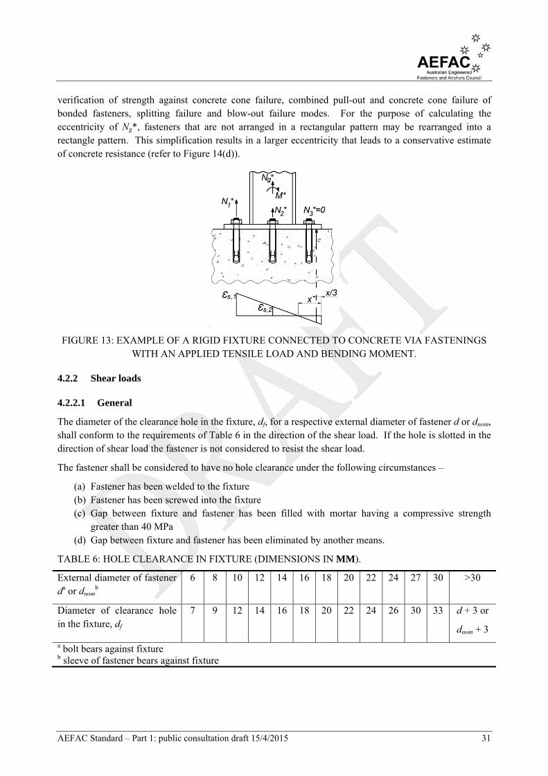
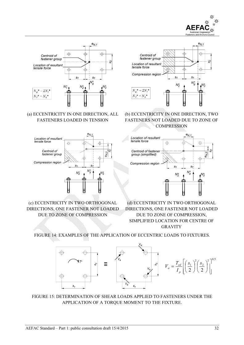
Where fasteners in a group resist different design tensile loads, Ni* (refer to Figure 13) the resultant design tensile load acting on the group, Ng*, acts at an eccentricity, eN, relative to the centroid of the fasteners resisting tension (refer to Figure 14). The eccentricity shall be calculated for consideration in the
AEFAC Standard – Part 1: public consultation draft 15/4/2015 31
verification of strength against concrete cone failure, combined pull-out and concrete cone failure of bonded fasteners, splitting failure and blow-out failure modes. For the purpose of calculating the eccentricity of Ng*, fasteners that are not arranged in a rectangular pattern may be rearranged into a rectangle pattern. This simplification results in a larger eccentricity that leads to a conservative estimate of concrete resistance (refer to Figure 14(d)).
FIGURE 13: EXAMPLE OF A RIGID FIXTURE CONNECTED TO CONCRETE VIA FASTENINGS WITH AN APPLIED TENSILE LOAD AND BENDING MOMENT.
4.2.2 Shear loads
4.2.2.1 General
The diameter of the clearance hole in the fixture, df, for a respective external diameter of fastener d or dnom, shall conform to the requirements of Table 6 in the direction of the shear load. If the hole is slotted in the direction of shear load the fastener is not considered to resist the shear load.
The fastener shall be considered to have no hole clearance under the following circumstances –
(a) Fastener has been welded to the fixture (b) Fastener has been screwed into the fixture (c) Gap between fixture and fastener has been filled with mortar having a compressive strength
greater than 40 MPa (d) Gap between fixture and fastener has been eliminated by another means.
TABLE 6: HOLE CLEARANCE IN FIXTURE (DIMENSIONS IN MM).
External diameter of fastener da or dnom
b 6 8 10 12 14 16 18 20 22 24 27 30 >30
Diameter of clearance hole in the fixture, df
7 9 12 14 16 18 20 22 24 26 30 33 d + 3 or
dnom + 3
a bolt bears against fixture b sleeve of fastener bears against fixture
AEFAC Standard – Part 1: public consultation draft 15/4/2015 32
(a) ECCENTRICITY IN ONE DIRECTION, ALL FASTENERS LOADED IN TENSION
(b) ECCENTRICITY IN ONE DIRECTION, TWO FASTENERS NOT LOADED DUE TO ZONE OF
COMPRESSION
(c) ECCENTRICITY IN TWO ORTHOGONAL DIRECTIONS, ONE FASTENER NOT LOADED
DUE TO ZONE OF COMPRESSION
(d) ECCENTRICITY IN TWO ORTHOGONAL DIRECTIONS, ONE FASTENER NOT LOADED
DUE TO ZONE OF COMPRESSION, SIMPLIFIED LOCATION FOR CENTRE OF
GRAVITY
FIGURE 14: EXAMPLES OF THE APPLICATION OF ECCENTRIC LOADS TO FIXTURES.
5.02
2
2
1
22
ss
I
TV
p
eda
FIGURE 15: DETERMINATION OF SHEAR LOADS APPLIED TO FASTENERS UNDER THE APPLICATION OF A TORQUE MOMENT TO THE FIXTURE.

AEFAC Standard – Part 1: public consultation draft 15/4/2015 33
(a) Two fasteners with a shear load parallel to edge
(b) Four fasteners with a shear load perpendicular to edge
(c) Four fasteners with an oblique shear load
FIGURE 16: DETERMINATION OF SHEAR LOADS APPLIED TO FASTENERS IN FIXTURES IN CLOSE PROXIMITY TO AN EDGE.
4.2.2.2 Load distribution
The distribution of shear load is considered to occur equally among all fasteners in a group under each of the following circumstances –
(a) The fasteners are distant to a free edge such that c > max(10hef, 60dnom) (b) Verification of steel failure (c) Verification of pry-out failure (d) A torsion moment is applied to the fixture (refer to Figure 15) (e) The shear load is applied parallel to the free edge (refer to Figure 16(a))
The direction of shear load influences the strength of fasteners located close to an edge as follows –
(a) When the component of applied shear load acts perpendicular and towards an edge (refer to Figure 16(b)), only fastener(s) located closest to the edge are effective in resisting concrete edge failure.
(b) The component of shear load acting parallel to an edge is considered to be equally distributed among all fasteners in the group (refer to Figure 16(c)).
(c) The component of shear load acting away from a free edge does not significantly influence the concrete edge strength and may be neglected when verifying concrete edge failure (refer to Figure 16(c)).
4.2.2.3 Shear load without a lever arm
(a) A shear load shall be considered to act without a lever arm under the following conditions – (i) The fixture is steel and is in contact with the fastener over a minimum length of 0.5tfix. (ii) Adequate restraint of the fixture is provided through: i) direct fixing of the fixture to the concrete
substrate, or ii) a levelling mortar of compressive strength at least equal to that of the base material and not less than 30 MPa, with a thickness no greater than tgrout < 0.5d over a rough concrete surface (refer to AS 3600) that provides complete coverage of the underside of the fixture.
(b) If the above conditions are not met the shear load is considered to be applied to a fastener with a lever arm. If only condition (b) above is not met the shear capacity of the fastener may be reduced without designing for a lever arm providing all of the following conditions are met – (i) There are a minimum of two fasteners in the direction of the applied shear load. (ii) The only action applied to the fixture is shear load.

AEFAC Standard – Part 1: public consultation draft 15/4/2015 34
(iii) The spacing of fasteners is greater than 10d, applicable in orthogonal directions in the case of an inclined shear load comprising two orthogonal components.
(iv) The thickness of a layer of grout – if any – is limited to tgrout < 5d for fasteners without a sleeve or tgrout < 5dnom for fasteners containing a sleeve, and not greater than 40 mm.
(v) a levelling mortar of compressive strength at least equal to that of the base material and not less than 30 MPa, over a rough concrete surface (refer to AS 3600) that provides complete coverage of the underside of the fixture.
4.2.2.4 Shear load with a lever arm
If the applied shear load acts with a lever arm (refer to Figure 17), the design bending moment acting on the fastener, M*, shall be calculated as follows –
M* =
M
alV
* (3)
where
M* = design bending moment acting on the fastener
V* = shear load applied to the fastener
la = lever arm of the shear force applied to the fastener
= a3 + e1
a3 = distance between the assumed point of restraint of the fastener loaded in shear and the surface of the concrete
= 0.5dnom
= 0 provided one of the following conditions exist –
i) a nut and washer are clamped to the surface of the concrete (or to the surface of anchor channel), or
ii) a layer of levelling mortar exists under the entire fixture that has a compressive strength at least equal to 30 MPa and a thickness tgrout < 0.5d
e1 = eccentricity of the applied shear load relative to the concrete surface, neglecting the thickness of a levelling grout or mortar
αM = parameter based on engineering experience that accounts for the degree of restraint of an anchor channel at the side of the fixture under consideration
= 1.0 for the condition of no restraint, assumed for fixtures that can freely rotate
= 2.0 for the condition of restraint, assumed for a fixture prevented from rotating
FIGURE 17: FIXTURE LOADED IN SHEAR WITH A LEVER ARM.

AEFAC Standard – Part 1: public consultation draft 15/4/2015 35
4.3 ANCHOR CHANNEL
4.3.1 General
The force resisted by each anchor in an anchor channel depends on the assumed anchor stiffness and the degree of restraint. The distribution of tension forces among anchors in anchor channel may be calculated by assuming the anchor channel to be a statically determinate beam system that is supported on anchors and has partial restraint at its ends. Under shear loading the distribution of applied load to individual anchors is influenced by the channel-to-concrete contact zone and the resultant pressure distribution.
Where the number of anchors in the anchor channel is limited to two, the calculation of loads resisted by each anchor may be performed assuming the anchor behaves as a simply supported beam with a length equal to anchor spacing. Alternatively, the triangle load distribution method may be used to calculate the load on each anchor in an anchor channel containing two or more anchors.
The design of an anchor channel for shear load applies only in the direction that is perpendicular to the longitudinal direction of the channel.
4.3.2 Tension loads
The tension resisted by each anchor in the channel, Ni* may be calculated by assuming a linear distribution of load over the influence length, li, and accounting for the condition of equilibrium as follows –
Ni* = kA’iN* (4)
where
k = n
iA1
'
1
(5)
A’i = ordinate on the normalised load distribution triangle with base length 2li, at the location of the anchor, i, under consideration
n = number of anchors located within the influence length of the anchor channel, li, on either side of the applied load (refer to Figure 18).
N* = design tensile load
li = ssI y 5.005.013
Iy = moment of inertia of channel relative to the y-axis of the channel
Where multiple loads are applied to the channel the principles of superposition may be employed to determine the load resisted by each anchor.
In the event that the exact position of the applied load on the channel is unknown, the most unfavourable position shall be assumed for each failure mode, such as directly over an anchor for steel rupture or concrete cone failure, or mid-way between anchors for channel bending failure.
Determination of the design bending moment acting on the channel, Mch*, due to an applied tension load, Nch*, shall be based upon the principle of a simply supported beam with a span equal to the spacing of the anchors.
AEFAC Standard – Part 1: public consultation draft 15/4/2015 36
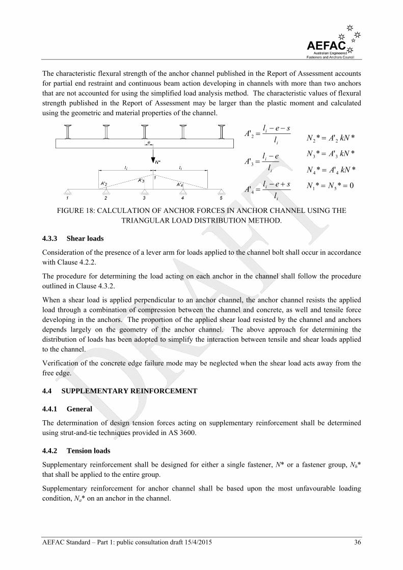
The characteristic flexural strength of the anchor channel published in the Report of Assessment accounts for partial end restraint and continuous beam action developing in channels with more than two anchors that are not accounted for using the simplified load analysis method. The characteristic values of flexural strength published in the Report of Assessment may be larger than the plastic moment and calculated using the geometric and material properties of the channel.
i
i
l
selA
2'
i
i
l
elA
3'
i
i
l
selA
4'
*'* 22 kNAN
*'* 33 kNAN
*'* 44 kNAN
0** 51 NN
FIGURE 18: CALCULATION OF ANCHOR FORCES IN ANCHOR CHANNEL USING THE TRIANGULAR LOAD DISTRIBUTION METHOD.
4.3.3 Shear loads
Consideration of the presence of a lever arm for loads applied to the channel bolt shall occur in accordance with Clause 4.2.2.
The procedure for determining the load acting on each anchor in the channel shall follow the procedure outlined in Clause 4.3.2.
When a shear load is applied perpendicular to an anchor channel, the anchor channel resists the applied load through a combination of compression between the channel and concrete, as well and tensile force developing in the anchors. The proportion of the applied shear load resisted by the channel and anchors depends largely on the geometry of the anchor channel. The above approach for determining the distribution of loads has been adopted to simplify the interaction between tensile and shear loads applied to the channel.
Verification of the concrete edge failure mode may be neglected when the shear load acts away from the free edge.
4.4 SUPPLEMENTARY REINFORCEMENT
4.4.1 General
The determination of design tension forces acting on supplementary reinforcement shall be determined using strut-and-tie techniques provided in AS 3600.
4.4.2 Tension loads
Supplementary reinforcement shall be designed for either a single fastener, N* or a fastener group, Nh* that shall be applied to the entire group.
Supplementary reinforcement for anchor channel shall be based upon the most unfavourable loading condition, Na* on an anchor in the channel.
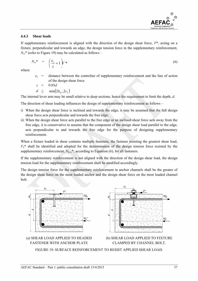
AEFAC Standard – Part 1: public consultation draft 15/4/2015 37
4.4.3 Shear loads
If supplementary reinforcement is aligned with the direction of the design shear force, V*, acting on a fixture, perpendicular and towards an edge, the design tension force in the supplementary reinforcement, Nre* (refer to Figure 19) may be calculated as follows –
Nre* = *1 Vz
es
(6)
where
es = distance between the centreline of supplementary reinforcement and the line of action of the design shear force
z ≈ 0.85d
d < 12,2min chef
The internal lever arm may be small relative to deep sections, hence the requirement to limit the depth, d.
The direction of shear loading influences the design of supplementary reinforcement as follows –
i) When the design shear force is inclined and towards the edge, it may be assumed that the full design shear force acts perpendicular and towards the free edge.
ii) When the design shear force acts parallel to the free edge or an inclined shear force acts away from the free edge, it is conservative to assume that the component of the design shear load parallel to the edge, acts perpendicular to and towards the free edge for the purpose of designing supplementary reinforcement.
When a fixture loaded in shear contains multiple fasteners, the fastener resisting the greatest shear load, Vh* shall be identified and adopted for the determination of the design tension force resisted by the supplementary reinforcement, Nh,re*, according to Equation (6), for all fasteners.
If the supplementary reinforcement is not aligned with the direction of the design shear load, the design tension load for the supplementary reinforcement shall be modified accordingly.
The design tension force for the supplementary reinforcement in anchor channels shall be the greater of the design shear force on the most loaded anchor and the design shear force on the most loaded channel bolt.
(a) SHEAR LOAD APPLIED TO HEADED FASTENER WITH ANCHOR PLATE
(b) SHEAR LOAD APPLIED TO FIXTURE CLAMPED BY CHANNEL BOLT.
FIGURE 19: SURFACE REINFORCEMENT TO RESIST APPLIED SHEAR LOAD.

AEFAC Standard – Part 1: public consultation draft 15/4/2015 38
5 D E T A I L I N G O F S U P P L E M E N T A R Y R E I N F O R C E M E N T
If supplementary reinforcement is to be included in the design of post-installed or cast-in fasteners to resist the entire load, it is not necessary to verify strength of the fastener to concrete cone failure for tensile loading (refer to Table 2 and Table 3) or concrete edge failure for shear loading (refer to Table 4 or Table 5).
The design of supplementary and surface reinforcement shall be in accordance with the requirements of AS 3600. Strength verifications relating to supplementary reinforcement in Table 2 to Table 5 shall be based on a development length for a level of stress in the reinforcing steel, σst not exceeding the yield strength of the reinforcing steel, fsy. Limitations on the geometry of a hook (mandrel) or cog are provided in AS 3600.
When designing supplementary reinforcement for a fastener group, the design shall be based on the most loaded fastener and an identical design adopted for all other fasteners in that group. The placement of supplementary reinforcement shall be symmetrical and as close to the fastener as practicable. Reinforcement positioned at a distance greater than 0.75hef is not considered to be effective. The placement of supplementary reinforcement should enclose surface reinforcement where possible.
Supplementary reinforcement in the concrete failure cone shall have a minimum anchorage length as follows –
i. l1 > 4db for bends, hooks or loops, or ii. l1 > 10db for straight bars with or without welded transverse bars
Anchorage of the supplementary reinforcement outside the concrete failure cone shall be for a minimum development length, Lst in accordance with AS 3600.
If the supplementary reinforcement is not adequately lapped with reinforcement in the structural element, the strength against concrete cone failure, NRk,c for the supplementary reinforcement shall be calculated in accordance with Clause 6.2.2, assuming hef is equal to the length of embedment of the supplementary reinforcement outside the concrete failure cone.
In addition to the supplementary reinforcement, surface reinforcement shall be provided to resist the forces determined from the strut-and-tie model as illustrated in Figure 20.
Underutilised reinforcement in the concrete member design may be utilised for supplementary reinforcement provided that the minimum detailing requirements for supplementary reinforcement outlined in this Standard are met.

AEFAC Standard – Part 1: public consultation draft 15/4/2015 39
(a) PLACEMENT OF SUPPLEMENTARY AND SURFACE
REINFORCEMENT TO RESIST CONCRETE CONE FAILURE.
(b) STRUT-AND-TIE MODEL FOR SUPPLEMENTARY AND SURFACE
REINFORCEMENT.
FIGURE 20: PLACEMENT OF SUPPLEMENTARY REINFORCEMENT AND SURFACE REINFORCEMENT FOR AN ASSUMED STRUT-AND-TIE MODEL TO RESIST CONCRETE CONE
FAILURE.
AEFAC Standard – Part 1: public consultation draft 15/4/2015 40
6 D E S I G N F O R T E N S I L E L O A D I N G
6.1 GENERAL
The characteristic strength to tensile loading for the modes of failure for post-installed fasteners and cast-in headed fasteners outlined in Table 2 is determined in accordance with Clause 6.2. The characteristic strength to tensile loading for the modes of failure for cast-in anchor channel outlined in Table 3 is determined in accordance with Clause 6.3.
6.2 POST-INSTALLED FASTENERS AND CAST-IN HEADED FASTENERS
The verifications in Table 2 shall apply.
6.2.1 Steel failure
The characteristic tensile steel strength of the fastener shall be calculated in accordance with AS 4100 based on the material properties of the fastener published in the Report of Assessment.
6.2.2 Concrete cone failure
6.2.2.1 General
The characteristic strength of a fastener, a group of fasteners or the tensioned fasteners in a group to concrete cone failure is given as follows –
NRk,c = NMNecNreNsNc
NccRk A
AN ,,,,0
,
,0,
(7)
where
NRk,c = characteristic strength of a fastener to concrete cone failure
N0Rk,c = characteristic strength of a fastener, remote from the effects of adjacent fasteners or edges
of the concrete member, to concrete cone failure given in Clause 6.2.2.2
Ac,N = actual projected area of the failure cone of the fastener that is limited by adjacent fasteners and edges of the concrete member given in Clause 6.2.2.3
A0c,N = reference projected area of the failure cone of the fastener given in Clause 6.2.2.3
ψs,N = parameter related to the distribution of stresses in the concrete due to the proximity of the fastener to an edge of the concrete member given in Clause 6.2.2.4
ψre,N = parameter accounting for the shell spalling effect given in Clause 6.2.2.5
ψec,N = parameter accounting for eccentricity of the resultant load in a fastener group given in Clause 6.2.2.6
ψM,N = parameter accounting for the effect of a compression force between the fixture and concrete given in Clause 6.2.2.7

AEFAC Standard – Part 1: public consultation draft 15/4/2015 41
6.2.2.2 Characteristic strength of a single fastener
The characteristic strength of a fastener, remote from the effects of adjacent fasteners or edges of the concrete member shall be taken as –
N0Rk,c = 5.1
9 .'. efc hfk (8)
with
k9 = kcr,N for cracked concrete may be taken as –
(i) 7.7 for post-installed fasteners (ii) 8.9 for cast-in headed fasteners = kucr,N for non-cacked concrete may be taken as – (i) 11.0 for post-installed fasteners (ii) 12.7 for cast-in headed fasteners
The parameters kcr,N and kucr,N may be found in the Report of Assessment.
6.2.2.3 Geometric effect of edge distance and spacing
The ratio of Ac,N/A0c,N takes into account the effect of adjacent fasteners and edges of the concrete member
on the characteristic strength of the fastener to concrete cone failure where –
A0c,N = reference projected area of a single fastener with an edge distance at least equal to 1.5hef
= scr,N.scr,N (9)
Ac,N = actual projected area that is limited by the edges of the concrete member (c < ccr,N) and overlapping areas of adjacent fasteners (s < scr,N).
The indicative characteristic spacing of headed fasteners and post-installed fasteners to ensure the transmission of the characteristic tensile strength of a single fastener is –
scr,N = 2ccr,N (10)
= 3hef (11)
ccr,N = characteristic edge distance given in the Report of Assessment
An example illustration of Ac,N and A0c,N is provided in Figure 21 and Figure 22.
A0c,N = scr,N x scr,N
(a) (b)
FIGURE 21: PROJECTED AREA OF THE CONCRETE CONE OF A SINGLE FASTENER.
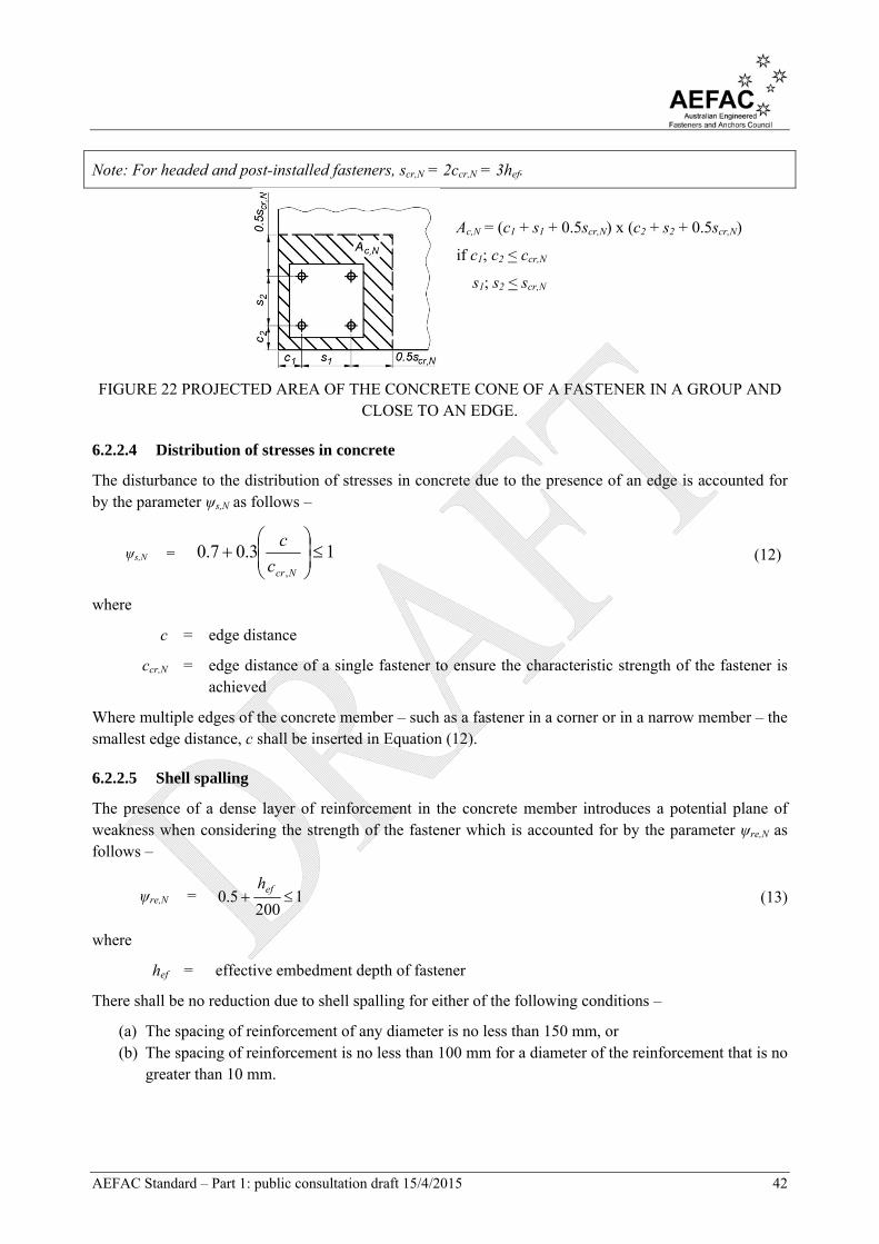
AEFAC Standard – Part 1: public consultation draft 15/4/2015 42
Note: For headed and post-installed fasteners, scr,N = 2ccr,N = 3hef.
Ac,N = (c1 + s1 + 0.5scr,N) x (c2 + s2 + 0.5scr,N)
if c1; c2 < ccr,N
s1; s2 < scr,N
FIGURE 22 PROJECTED AREA OF THE CONCRETE CONE OF A FASTENER IN A GROUP AND CLOSE TO AN EDGE.
6.2.2.4 Distribution of stresses in concrete
The disturbance to the distribution of stresses in concrete due to the presence of an edge is accounted for by the parameter ψs,N as follows –
ψs,N = 13.07.0,
Ncrc
c (12)
where
c = edge distance
ccr,N = edge distance of a single fastener to ensure the characteristic strength of the fastener is achieved
Where multiple edges of the concrete member – such as a fastener in a corner or in a narrow member – the smallest edge distance, c shall be inserted in Equation (12).
6.2.2.5 Shell spalling
The presence of a dense layer of reinforcement in the concrete member introduces a potential plane of weakness when considering the strength of the fastener which is accounted for by the parameter ψre,N as follows –
ψre,N = 1200
5.0 efh (13)
where
hef = effective embedment depth of fastener
There shall be no reduction due to shell spalling for either of the following conditions –
(a) The spacing of reinforcement of any diameter is no less than 150 mm, or (b) The spacing of reinforcement is no less than 100 mm for a diameter of the reinforcement that is no
greater than 10 mm.

AEFAC Standard – Part 1: public consultation draft 15/4/2015 43
6.2.2.6 Eccentricity of loading on a fastener group
The parameter ψec,N accounts for a group effect when there is a difference in tension loads resisted by individual fasteners in a group as follows –
ψec,N = 1/.21
1
,
NcrN se
(14)
where
eN = eccentricity of the resultant tension force acting on a group of fasteners relative to the centre of gravity of the tensioned fasteners
scr,N = characteristic spacing of fastener to ensure the transmission of the characteristic strength of the fastener
If there is an eccentricity in two orthogonal directions, the parameter ψec,N should be determined for both directions and the product of these values substituted in Equation (7).
6.2.2.7 Compression between fixture and concrete
The parameter ψM,N accounts for the effect of a compression force between the fixture and concrete as follows –
ψM,N = 1 under the following conditions
(i) Fastenings that have an edge c < 1.5hef (ii) Fastenings that are distant from edge effects (c > 1.5hef) that have an applied
bending moment and tension force where Nc*/N* < 0.8, or (iii) Fastenings with z/hef > 1.5
= 13
22
efh
z
(15)
for all other applications
where
z = internal lever arm
hef = effective embedment depth of the fastener
Where bending is present in two directions the lever arm, z shall be determined for the combined bending moments in both directions and the axial force.
6.2.2.8 Narrow concrete member
The concrete member is considered to be narrow if three or more edge distances are less than the characteristic edge distance, ccr,N as illustrated in Figure 23 (a) and (b). A more precise estimation of strength is obtained with a modified effective embedment depth, h’ef as follows –
h’ef = efNcr
hc
c
,
max
for individual fasteners
(16)
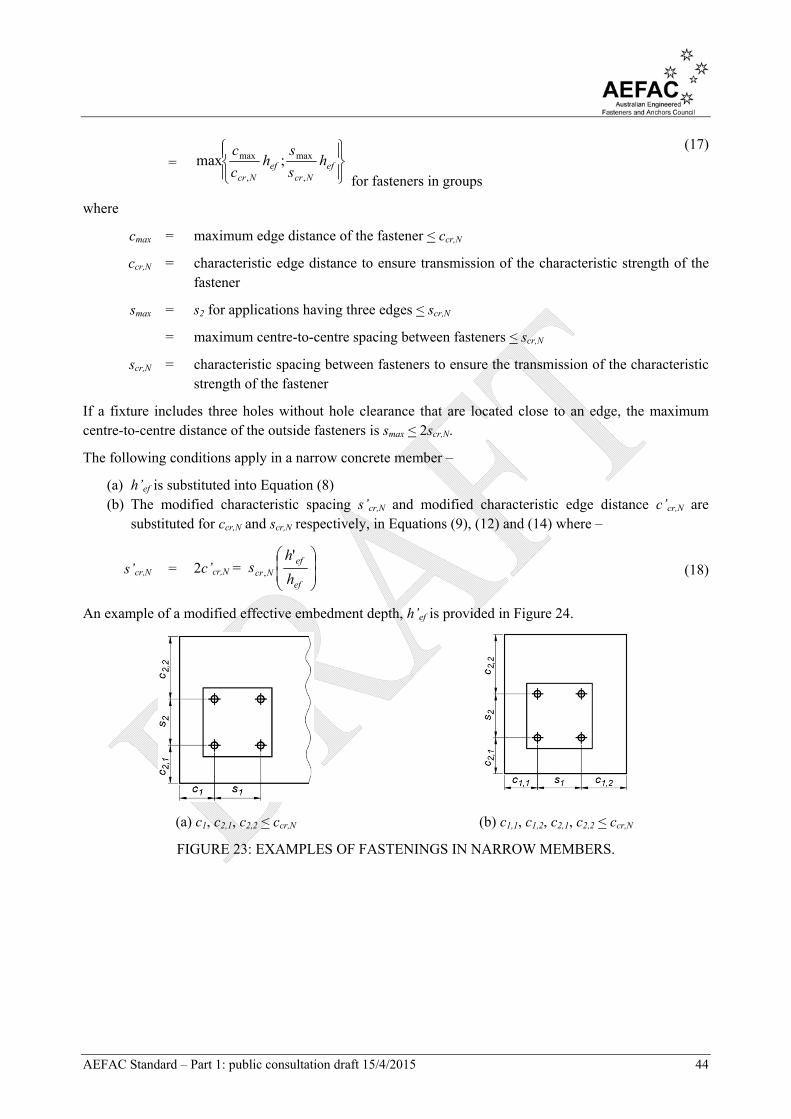
AEFAC Standard – Part 1: public consultation draft 15/4/2015 44
=
efNcr
efNcr
hs
sh
c
c
,
max
,
max ;max for fasteners in groups
(17)
where
cmax = maximum edge distance of the fastener < ccr,N
ccr,N = characteristic edge distance to ensure transmission of the characteristic strength of the fastener
smax = s2 for applications having three edges < scr,N
= maximum centre-to-centre spacing between fasteners < scr,N
scr,N = characteristic spacing between fasteners to ensure the transmission of the characteristic strength of the fastener
If a fixture includes three holes without hole clearance that are located close to an edge, the maximum centre-to-centre distance of the outside fasteners is smax < 2scr,N.
The following conditions apply in a narrow concrete member –
(a) h’ef is substituted into Equation (8) (b) The modified characteristic spacing s’cr,N and modified characteristic edge distance c’cr,N are
substituted for ccr,N and scr,N respectively, in Equations (9), (12) and (14) where –
s’cr,N = 2c’cr,N =
ef
efNcr h
hs
', (18)
An example of a modified effective embedment depth, h’ef is provided in Figure 24.
(a) c1, c2,1, c2,2 < ccr,N (b) c1,1, c1,2, c2,1, c2,2 < ccr,N
FIGURE 23: EXAMPLES OF FASTENINGS IN NARROW MEMBERS.

AEFAC Standard – Part 1: public consultation draft 15/4/2015 45
(a) PLAN VIEW (b) CROSS-SECTION (SIDE VIEW) (c) CROSS-SECTION (END VIEW).
FIGURE 24: CALCULATION OF h’ef FOR A FIXTURE CONTAINING TWO FASTENERS.
6.2.3 Pull-out failure
Pull-out failure shall be considered for post-installed mechanical and cast-in headed fasteners with the characteristic strength against pull-out failure provided in the Report of Assessment.
The pull-out strength of a cast-in headed fastener is limited by the bearing pressure under the head of the fastener given by –
NRk,p = k1Ahf’c (19)
where
k1 = parameter relating to the state of the concrete
= 8.0 for fasteners in cracked concrete
= 11.2 for fasteners in uncracked concrete
Ah = area of the load-bearing head of the fastener
= 22
4ddh
(20)
dh = diameter of head of fastener
< 6th + d
th = thickness of the head of the headed fastener
d = diameter of the shank of the fastener
f’c = characteristic compressive strength of concrete
6.2.4 Combined pull-out and concrete cone failure for post-installed chemical fasteners
6.2.4.1 General
The strength of a single chemical fastener in tension or a fastener in tension in a group of fasteners to combined pull-out and concrete cone failure may be estimated as follows –
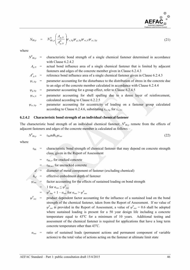
AEFAC Standard – Part 1: public consultation draft 15/4/2015 46
NRk,p = NpecNreNpgNpsNp
NppRk
A
AN ,,,,0
,
,0,
(21)
where
N0Rk,p = characteristic bond strength of a single chemical fastener determined in accordance
with Clause 6.2.4.2 Ap,N = actual bond influence area of a single chemical fastener that is limited by adjacent
fasteners and edges of the concrete member given in Clause 6.2.4.3 A0
p,N = reference bond influence area of a single chemical fastener given in Clause 6.2.4.3
ψs,Np = parameter accounting for the disturbance to the distribution of stress in the concrete due to an edge of the concrete member calculated in accordance with Clause 6.2.4.4
ψg,Np = parameter accounting for a group effect, refer to Clause 6.2.4.5
ψre,N = parameter accounting for shell spalling due to a dense layer of reinforcement, calculated according to Clause 6.2.2.5
ψec,Np = parameter accounting for eccentricity of loading on a fastener group calculated according to Clause 6.2.4.6, substituting scr,Np for scr,N.
6.2.4.2 Characteristic bond strength of an individual chemical fastener
The characteristic bond strength of an individual chemical fastener, N0Rk,p remote from the effects of
adjacent fasteners and edges of the concrete member is calculated as follows –
N0Rk,p = τRkπdhefψsus (22)
where
τRk = characteristic bond strength of chemical fastener that may depend on concrete strength class, given in the Report of Assessment
= τRk,cr for cracked concrete
= τRk,ucr for uncracked concrete
d = diameter of metal component of fastener (excluding chemical)
hef = effective embedment depth of fastener
ψsus = factor accounting for the effects of sustained loading on bond strength
= 1 for αsus < ψ0sus
= ψ0sus + 1 – αsus for αsus > ψ0
sus
ψ0sus = product dependent factor accounting for the influence of a sustained load on the bond
strength of the chemical fastener, taken from the Report of Assessment. If no value of ψ0
sus is provided in the Report of Assessment, a value of ψ0sus = 0.6 shall be adopted
where sustained loading is present for a 50 year design life including a concrete temperature equal to 43oC for a minimum of 10 years. Additional testing and assessment of the chemical fastener is required for applications that have a long term concrete temperature other than 43oC.
αsus = ratio of sustained loads (permanent actions and permanent component of variable actions) to the total value of actions acting on the fastener at ultimate limit state

AEFAC Standard – Part 1: public consultation draft 15/4/2015 47
6.2.4.3 Geometric effect of edge distance and spacing
The geometric effect of edge distance and spacing is accounted for via the ratio Ap,N/A0p,N where –
Ap,N = actual bond influence area of a chemical fastener that is limited by the edges of the concrete member (c < ccr,Np) and overlapping areas from adjacent fasteners (s < scr,Np)
A0p,N = reference bond influence area of an individual chemical fastener
= scr,Np scr,Np (23)
scr,Np = efsusRk hd 33.7 (24)
d = diameter of metal component of fastener (excludes chemical)
τRk = value of τRk,ucr for f’c = 20 MPa, obtained from the Report of Assessment
hef = effective embedment depth of fastener
ccr,Np = scr,Np/2 (25)
ψsus = factor accounting for the effects of sustained loading on bond strength (refer to Clause 6.2.4.2)
6.2.4.4 Disturbance to the distribution of stresses
The disturbance to the distribution of stress in the concrete due to an edge of the concrete member is calculated according to Clause 6.2.2.4 by substituting ψs,Np for ψs,N and ccr,Np for ccr,N.
6.2.4.5 Effect of closely spaced fasteners
The group effect of closely spaced fasteners is accounted for by the parameter ψg,Np as follows –
ψg,Np = 110,
5.0
,
0,
Npg
NpcrNpg s
s (26)
where
ψ0g,Np = 11
5.1
,
cRk
Rknn
(27)
τRk,c = cef fhd
k'8
(28)
k8 = parameter relating to the state of the concrete
= 7.7 for cracked concrete
= 11.0 for uncracked concrete
s = spacing of fasteners, taken as the mean value in the event of unequal spacing
scr,Np = characteristic spacing of fasteners in accordance with Equation (24)
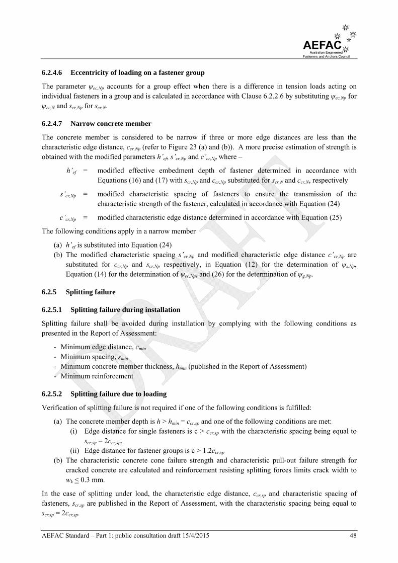
AEFAC Standard – Part 1: public consultation draft 15/4/2015 48
6.2.4.6 Eccentricity of loading on a fastener group
The parameter ψec,Np accounts for a group effect when there is a difference in tension loads acting on individual fasteners in a group and is calculated in accordance with Clause 6.2.2.6 by substituting ψec,Np for ψec,N and scr,Np for scr,N.
6.2.4.7 Narrow concrete member
The concrete member is considered to be narrow if three or more edge distances are less than the characteristic edge distance, ccr,Np (refer to Figure 23 (a) and (b)). A more precise estimation of strength is obtained with the modified parameters h’ef, s’cr,Np and c’cr,Np where –
h’ef = modified effective embedment depth of fastener determined in accordance with Equations (16) and (17) with scr,Np and ccr,Np substituted for scr,N and ccr,N, respectively
s’cr,Np = modified characteristic spacing of fasteners to ensure the transmission of the characteristic strength of the fastener, calculated in accordance with Equation (24)
c’cr,Np = modified characteristic edge distance determined in accordance with Equation (25)
The following conditions apply in a narrow member
(a) h’ef is substituted into Equation (24) (b) The modified characteristic spacing s’cr,Np and modified characteristic edge distance c’cr,Np are
substituted for ccr,Np and scr,Np respectively, in Equation (12) for the determination of ψs,Np, Equation (14) for the determination of ψec,Np, and (26) for the determination of ψg,Np.
6.2.5 Splitting failure
6.2.5.1 Splitting failure during installation
Splitting failure shall be avoided during installation by complying with the following conditions as presented in the Report of Assessment:
- Minimum edge distance, cmin - Minimum spacing, smin - Minimum concrete member thickness, hmin (published in the Report of Assessment) - Minimum reinforcement
6.2.5.2 Splitting failure due to loading
Verification of splitting failure is not required if one of the following conditions is fulfilled:
(a) The concrete member depth is h > hmin = ccr,sp and one of the following conditions are met: (i) Edge distance for single fasteners is c > ccr,sp with the characteristic spacing being equal to
scr,sp = 2ccr,sp. (ii) Edge distance for fastener groups is c > 1.2ccr,sp
(b) The characteristic concrete cone failure strength and characteristic pull-out failure strength for cracked concrete are calculated and reinforcement resisting splitting forces limits crack width to wk < 0.3 mm.
In the case of splitting under load, the characteristic edge distance, ccr,sp and characteristic spacing of fasteners, scr,sp are published in the Report of Assessment, with the characteristic spacing being equal to scr,sp = 2ccr,sp.
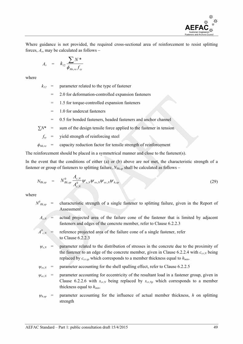
AEFAC Standard – Part 1: public consultation draft 15/4/2015 49
Where guidance is not provided, the required cross-sectional area of reinforcement to resist splitting forces, As, may be calculated as follows –
As = syreMs f
Nk
,12
*
where
k12 = parameter related to the type of fastener
= 2.0 for deformation-controlled expansion fasteners
= 1.5 for torque-controlled expansion fasteners
= 1.0 for undercut fasteners
= 0.5 for bonded fasteners, headed fasteners and anchor channel
∑N* = sum of the design tensile force applied to the fastener in tension
fsy = yield strength of reinforcing steel
ϕMs,re = capacity reduction factor for tensile strength of reinforcement
The reinforcement should be placed in a symmetrical manner and close to the fastener(s).
In the event that the conditions of either (a) or (b) above are not met, the characteristic strength of a fastener or group of fasteners to splitting failure, NRk,sp shall be calculated as follows –
NRk,sp = sphNecNreNsNc
NcspRk A
AN ,,,,0
,
,0, (29)
where
N0Rk,sp = characteristic strength of a single fastener to splitting failure, given in the Report of
Assessment
Ac,N = actual projected area of the failure cone of the fastener that is limited by adjacent fasteners and edges of the concrete member, refer to Clause 6.2.2.3
A0c,N = reference projected area of the failure cone of a single fastener, refer
to Clause 6.2.2.3
ψs,N = parameter related to the distribution of stresses in the concrete due to the proximity of the fastener to an edge of the concrete member, given in Clause 6.2.2.4 with ccr,N being replaced by ccr,sp which corresponds to a member thickness equal to hmin.
ψre,N = parameter accounting for the shell spalling effect, refer to Clause 6.2.2.5
ψec,N = parameter accounting for eccentricity of the resultant load in a fastener group, given in Clause 6.2.2.6 with scr,N being replaced by scr,Np which corresponds to a member thickness equal to hmin.
ψh,sp = parameter accounting for the influence of actual member thickness, h on splitting strength

AEFAC Standard – Part 1: public consultation draft 15/4/2015 50
= 25.1
;1max
3/2
min
13/2
min
h
ch
h
h ef
(30)
If multiple member thicknesses, h are published in the Report of Assessment, the adopted characteristic edge distance for splitting failure, ccr,sp shall correspond to the adopted member thickness in Equation (30).
If the characteristic strength of a single fastener to splitting failure, N0Rk,sp is not published in the Report of
Assessment, it may be conservatively estimated as follows –
N0Rk,sp = 0
,, ,min cRkpRk NN (31)
where
NRk,p = characteristic pull-out strength for post-installed mechanical and cast-in fasteners determined in accordance with Clause 6.2.3
N0Rk,c = characteristic concrete cone strength for post-installed chemical fasteners, determined
in accordance with Clause 6.2.2.2
6.2.6 Blow-out failure
6.2.6.1 General
The strength against blow-out failure is a consideration for post-installed mechanical and cast-in headed fasteners undercut anchors acting as headed fasteners if the edge distance is c < 0.5hef. The characteristic strength for blow-out failure shall be considered in each direction independently as follows –
NRk,cb = NbecNbgNbsNbc
NbccbRk
A
AN ,,,0
,
,0,
(32)
where
N0Rk,cb = characteristic strength of a single fastener remote from the effects of adjacent fasteners
and edges of the concrete member, refer to Clause 6.2.6.2
Ac,Nb = actual projected area for the fastener that is limited by the edges of the concrete member (c2 < 2c1), the presence of adjacent fasteners (s < 4c1) or the member thickness, refer to Clause 6.2.6.3
A0c,Nb = reference projected area of a single fastener with an edge distance equal to c1 (refer to
Figure 25(b)), refer to Clause 6.2.6.3
ψs,Nb = parameter accounting for the disturbance of stresses in the concrete due to the close proximity of the fastener to a corner of the concrete member, refer to Clause 6.2.6.4
ψg,Nb = parameter accounting for a group effect, refer to Clause 6.2.6.5
ψec,Nb = parameter accounting for eccentricity of loading on a fastener group, refer to Clause 6.2.6.6
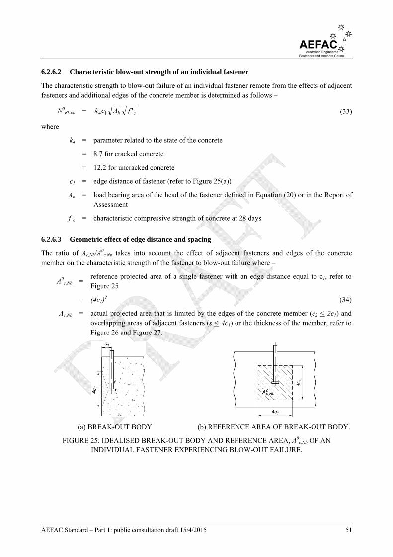
AEFAC Standard – Part 1: public consultation draft 15/4/2015 51
6.2.6.2 Characteristic blow-out strength of an individual fastener
The characteristic strength to blow-out failure of an individual fastener remote from the effects of adjacent fasteners and additional edges of the concrete member is determined as follows –
N0Rk,cb = ch fAck '14 (33)
where
k4 = parameter related to the state of the concrete
= 8.7 for cracked concrete
= 12.2 for uncracked concrete
c1 = edge distance of fastener (refer to Figure 25(a))
Ah = load bearing area of the head of the fastener defined in Equation (20) or in the Report of Assessment
f’c = characteristic compressive strength of concrete at 28 days
6.2.6.3 Geometric effect of edge distance and spacing
The ratio of Ac,Nb/A0
c,Nb takes into account the effect of adjacent fasteners and edges of the concrete member on the characteristic strength of the fastener to blow-out failure where –
A0c,Nb =
reference projected area of a single fastener with an edge distance equal to c1, refer to Figure 25
= (4c1)2 (34)
Ac,Nb = actual projected area that is limited by the edges of the concrete member (c2 < 2c1) and overlapping areas of adjacent fasteners (s < 4c1) or the thickness of the member, refer to Figure 26 and Figure 27.
(a) BREAK-OUT BODY (b) REFERENCE AREA OF BREAK-OUT BODY.
FIGURE 25: IDEALISED BREAK-OUT BODY AND REFERENCE AREA, A0c,Nb OF AN
INDIVIDUAL FASTENER EXPERIENCING BLOW-OUT FAILURE.
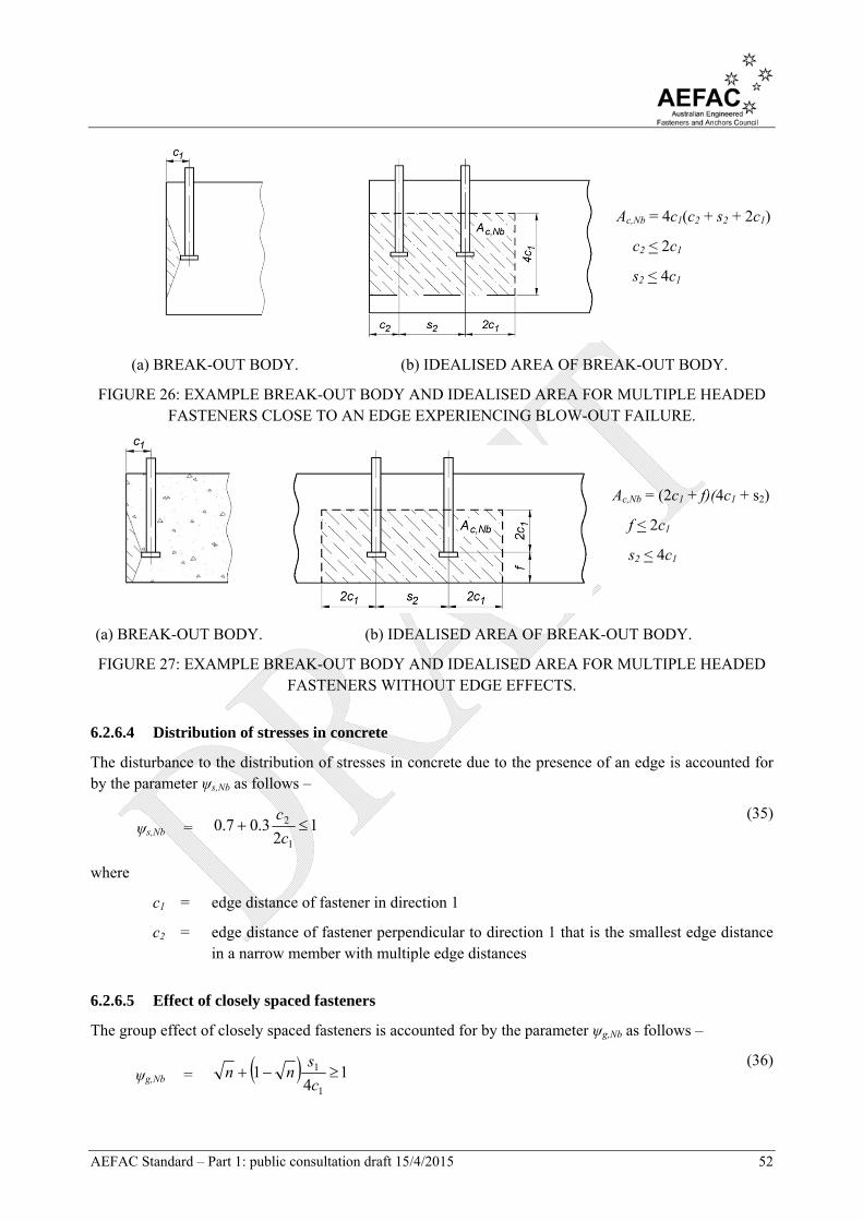
AEFAC Standard – Part 1: public consultation draft 15/4/2015 52
Ac,Nb = 4c1(c2 + s2 + 2c1)
c2 < 2c1
s2 < 4c1
(a) BREAK-OUT BODY. (b) IDEALISED AREA OF BREAK-OUT BODY.
FIGURE 26: EXAMPLE BREAK-OUT BODY AND IDEALISED AREA FOR MULTIPLE HEADED FASTENERS CLOSE TO AN EDGE EXPERIENCING BLOW-OUT FAILURE.
Ac,Nb = (2c1 + f)(4c1 + s2)
f < 2c1
s2 < 4c1
(a) BREAK-OUT BODY. (b) IDEALISED AREA OF BREAK-OUT BODY.
FIGURE 27: EXAMPLE BREAK-OUT BODY AND IDEALISED AREA FOR MULTIPLE HEADED FASTENERS WITHOUT EDGE EFFECTS.
6.2.6.4 Distribution of stresses in concrete
The disturbance to the distribution of stresses in concrete due to the presence of an edge is accounted for by the parameter ψs,Nb as follows –
ψs,Nb = 12
3.07.01
2 c
c
(35)
where
c1 = edge distance of fastener in direction 1
c2 = edge distance of fastener perpendicular to direction 1 that is the smallest edge distance in a narrow member with multiple edge distances
6.2.6.5 Effect of closely spaced fasteners
The group effect of closely spaced fasteners is accounted for by the parameter ψg,Nb as follows –
ψg,Nb = 14
11
1 c
snn
(36)

AEFAC Standard – Part 1: public consultation draft 15/4/2015 53
where
n = number of fasteners in a row parallel to the edge of the concrete member
s1 = spacing of fasteners in a group in direction 1
< 4c1
c1 = edge distance of fastener
6.2.6.6 Eccentricity of loading on a fastener group
The parameter ψec,Nb accounts for a group effect when there is a difference in tension loads acting on individual fasteners in a group and is calculated in accordance with Clause 6.2.2.6 by substituting ψec,Nb for ψec,N and scr,Nb for scr,N where –
scr,Nb = 4c1 (37)
6.2.7 Supplementary reinforcement
Should the fastener design include provision for supplementary reinforcement, the supplementary reinforcement shall be designed in accordance with AS 3600. The failure modes consideration in the design of supplementary reinforcement shall include the following –
(a) Steel fracture of the supplementary reinforcement (b) Anchorage failure of the supplementary reinforcement
6.3 CAST-IN ANCHOR CHANNEL
The verifications in Table 3 shall apply.
6.3.1 Steel failure
The following values for characteristic resistance are provided in the Report of Assessment –
(i) Channel bolt fracture, NRk,s (ii) Anchor fracture, NRk,s,a (iii) Connection between anchor and channel, NRk,s,c (iv) Basic value for local channel, N0
Rk,s,l (v) Local flexure of channel lip, NRk,s,l (vi) Flexure of channel, MRk,s,flex
6.3.2 Concrete cone failure
The characteristic strength of a single fastener in a channel bar to concrete cone failure is calculated as follows –
NRk,c = NreNcchNechNschcRkN ,,,,,,,
0, ... (38)
where
NRk,c = characteristic strength of a single fastener in a channel bar to concrete cone failure
N0Rk,c = characteristic strength of a fastener, remote from the effects of adjacent fasteners or
edges of the concrete member, to concrete cone failure calculated in accordance with

AEFAC Standard – Part 1: public consultation draft 15/4/2015 54
Clause 6.2.2.2.
ψch,s,N = parameter accounting for the influence of neighbouring fasteners on the concrete cone strength of a single fastener in the channel bar given in Clause 6.3.2.1
ψch,e,N = parameter accounting for the influence of an edge of the concrete member on the concrete cone strength given in Clause 6.3.2.2
ψch,c,N = parameter accounting for the influence of a corner on the concrete cone strength, given in Clause 6.3.2.3
ψre,N = parameter accounting for the shell spalling effect, given in Clause 6.2.2.5
6.3.2.1 Influence of neighbouring fasteners
The influence of neighbouring fasteners on the concrete cone strength is calculated as follows –
ψch,s,N =
1
11
1
1
5.1
,
chn
i o
i
Ncr
i
N
N
s
s
(39)
where
nch,N = number of fasteners within a distance equal to scr,N of the fastener under consideration (refer to Figure 28
si = distance between fastener under consideration and neighbouring fastener ‘i’
scr,N = characteristic spacing of the fastener to ensure the characteristic tensile strength of a single fastener
= efef
efhh
h3
1803.18.22
(40)
Ni = tension force in an influencing fastener ‘i’
No = tension force in the anchor under consideration
FIGURE 28: EXAMPLE OF ANCHOR CHANNEL CONTAINING MULTIPLE POINT LOADS.
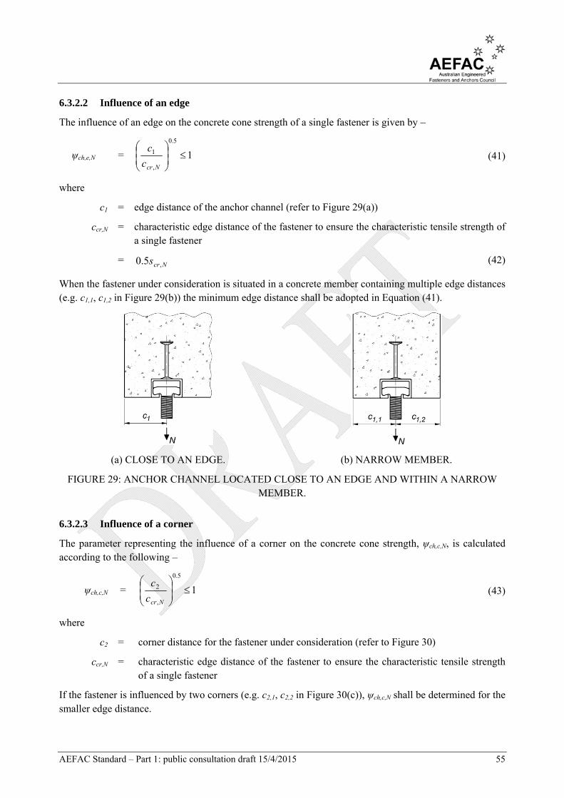
AEFAC Standard – Part 1: public consultation draft 15/4/2015 55
6.3.2.2 Influence of an edge
The influence of an edge on the concrete cone strength of a single fastener is given by –
ψch,e,N = 1
5.0
,
1
Ncrc
c (41)
where
c1 = edge distance of the anchor channel (refer to Figure 29(a))
ccr,N = characteristic edge distance of the fastener to ensure the characteristic tensile strength of a single fastener
= Ncrs ,5.0 (42)
When the fastener under consideration is situated in a concrete member containing multiple edge distances (e.g. c1,1, c1,2 in Figure 29(b)) the minimum edge distance shall be adopted in Equation (41).
(a) CLOSE TO AN EDGE. (b) NARROW MEMBER.
FIGURE 29: ANCHOR CHANNEL LOCATED CLOSE TO AN EDGE AND WITHIN A NARROW MEMBER.
6.3.2.3 Influence of a corner
The parameter representing the influence of a corner on the concrete cone strength, ψch,c,N, is calculated according to the following –
ψch,c,N = 1
5.0
,
2
Ncrc
c (43)
where
c2 = corner distance for the fastener under consideration (refer to Figure 30)
ccr,N = characteristic edge distance of the fastener to ensure the characteristic tensile strength of a single fastener
If the fastener is influenced by two corners (e.g. c2,1, c2,2 in Figure 30(c)), ψch,c,N shall be determined for the smaller edge distance.
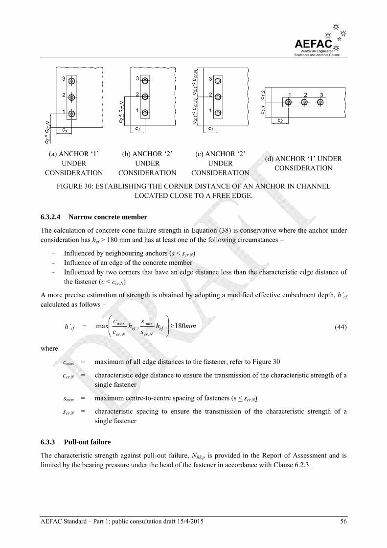
AEFAC Standard – Part 1: public consultation draft 15/4/2015 56
(a) ANCHOR ‘1’ UNDER
CONSIDERATION
(b) ANCHOR ‘2’ UNDER
CONSIDERATION
(c) ANCHOR ‘2’ UNDER
CONSIDERATION
(d) ANCHOR ‘1’ UNDER CONSIDERATION
FIGURE 30: ESTABLISHING THE CORNER DISTANCE OF AN ANCHOR IN CHANNEL LOCATED CLOSE TO A FREE EDGE.
6.3.2.4 Narrow concrete member
The calculation of concrete cone failure strength in Equation (38) is conservative where the anchor under consideration has hef > 180 mm and has at least one of the following circumstances –
- Influenced by neighbouring anchors (s < scr,N) - Influence of an edge of the concrete member - Influenced by two corners that have an edge distance less than the characteristic edge distance of
the fastener (c < ccr,N)
A more precise estimation of strength is obtained by adopting a modified effective embedment depth, h’ef calculated as follows –
h’ef = mmhs
sh
c
cef
Ncref
Ncr
180,max,
max
,
max
(44)
where
cmax = maximum of all edge distances to the fastener, refer to Figure 30
ccr,N = characteristic edge distance to ensure the transmission of the characteristic strength of a single fastener
smax = maximum centre-to-centre spacing of fasteners (s < scr,N)
scr,N = characteristic spacing to ensure the transmission of the characteristic strength of a single fastener
6.3.3 Pull-out failure
The characteristic strength against pull-out failure, NRk,p is provided in the Report of Assessment and is limited by the bearing pressure under the head of the fastener in accordance with Clause 6.2.3.
AEFAC Standard – Part 1: public consultation draft 15/4/2015 57
6.3.4 Splitting failure
6.3.4.1 Splitting failure during installation
The relevant provisions of Clause 6.2.5.1 apply to prevent splitting failure during anchor channel installation.
6.3.4.2 Splitting failure due to loading
The relevant provisions of Clause 6.2.5.2 apply to prevent splitting failure due to loading with consideration of the anchor channel acting as a group.
In the event that verification of splitting failure is required the characteristic strength to splitting failure, NRk,sp shall be calculated as follows –
NRk,sp = sphNrechNcchNechNschRkN ,,,,,,,,,0 (45)
where
N0Rk = min(NRk,p, N
0Rk,c) (46)
NRk,p = characteristic pull-out strength of fastener, given in Clause 6.2.3
N0Rk,c = characteristic concrete cone strength, given in Clause 6.2.2.2
ψch,s,N = parameter accounting for the influence of neighbouring fasteners, given by Equation 6.3.2.1
ψch,e,N = parameter accounting for the influence of an edge of the concrete member, given by Equation 0
ψch,c,N = parameter accounting for the influence of a corner, given by Equation 6.3.2.3
ψre,N = parameter accounting for the shell spalling effect, given in Clause 6.2.2.5
ψh,sp = parameter accounting for the influence of actual member thickness, h, given in Clause 6.2.5.2
The values scr,sp and ccr,sp replace scr,N and ccr,N, respectively in the determination of ψch,s,N, ψch,e,N, and ψch,c,N and correspond to a minimum allowable member thickness, hmin.
6.3.5 Blow-out failure
If the fastener has an edge distance greater than c = 0.5hef, verification for blow-out failure is not required. For lesser edge distances, the strength against blow-out failure is calculated as follows –
NRk,cb = NbhchNbcchNbschcbRkN ,,,,,,0
, (47)
where
N0Rk,cb = characteristic strength of a single fastener to blow-out failure given in Clause 6.2.6.2.
ψch,s,Nb = parameter accounting for the influence of neighbouring fasteners calculated according to Clause 6.3.2.1 by substituting scr,Nb for scr,N, where scr,Nb = 4c1.
ψch,c,Nb = parameter accounting for the influence of a corner of the concrete member, calculated according to Clause 6.3.2.3and substituting ψch,c,Nb for ψch,c,N and ccr,Nb for ccr,N where

AEFAC Standard – Part 1: public consultation draft 15/4/2015 58
ccr,Nb = 0.5scr,Nb.
ψch,h,Nb = parameter accounting for the influence of thickness of the concrete member, given in Clause 6.3.5.1.
6.3.5.1 Thickness of concrete member
Where the distance between the head of the fastener and the upper or lower surface of the concrete member, f is less than or equal to 2c1 (refer to Figure 31), the influence of member thickness on the blow-out strength is accounted for as follows –
ψch,h,Nb = 14
2
4 1
1
1
c
fc
c
fhef (48)
where
hef = effective embedment depth of the fastener
f = distance between the head of the fastener and the upper or lower surface of the concrete member, refer to Figure 31
c1 = edge distance in direction 1
FIGURE 31: ANCHOR CHANNEL LOCATED IN A THIN CONCRETE MEMBER.
6.3.6 Supplementary reinforcement failure
Should the design of anchor channel include provision for supplementary reinforcement (see detailing requirements in Figure 32), Clause 6.2.7 shall be followed.
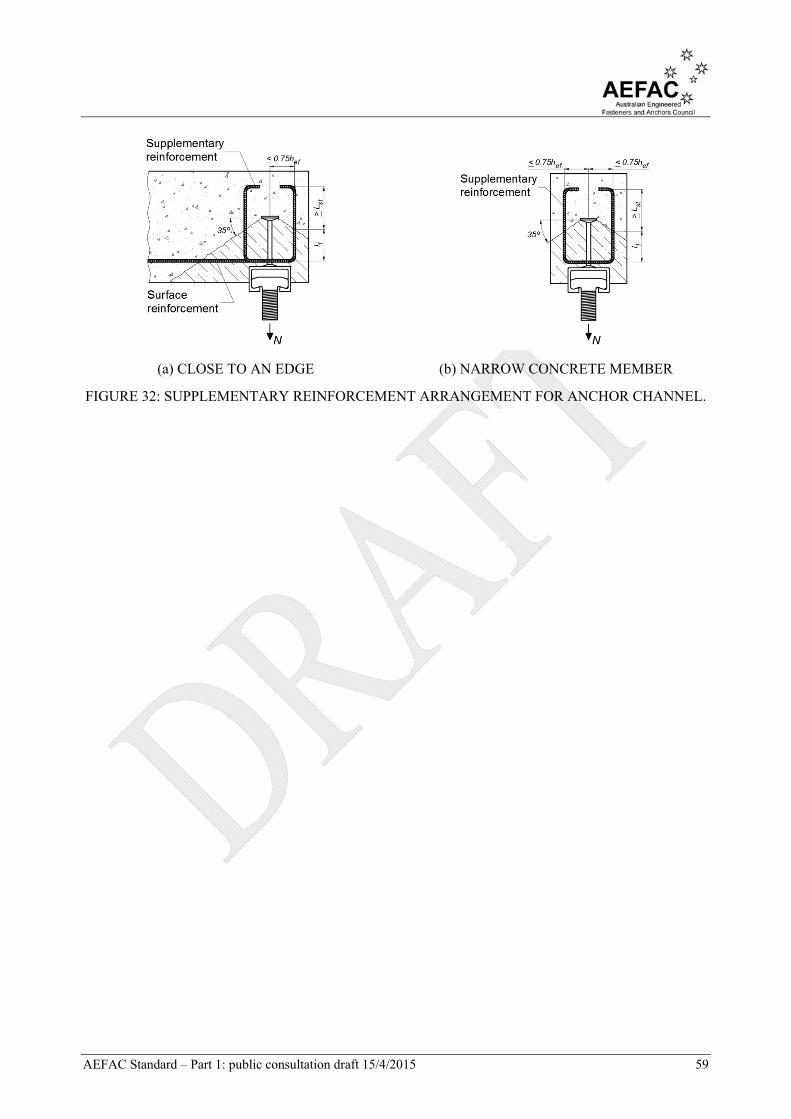
AEFAC Standard – Part 1: public consultation draft 15/4/2015 59
(a) CLOSE TO AN EDGE (b) NARROW CONCRETE MEMBER
FIGURE 32: SUPPLEMENTARY REINFORCEMENT ARRANGEMENT FOR ANCHOR CHANNEL.

AEFAC Standard – Part 1: public consultation draft 15/4/2015 60
7 D E S I G N F O R S H E A R L O A D I N G
7.1 GENERAL
The characteristic strength to shear loading for the modes of failure for post-installed fasteners and cast-in headed fasteners outlined in Table 4 is determined in accordance with Clause 6.2. The characteristic strength to shear loading for the modes of failure for anchor channel outlined in Table 5 is determined in accordance with Clause 6.3.
7.2 POST-INSTALLED FASTENERS AND CAST-IN HEADED FASTENERS
The verifications in Table 4 shall apply.
7.2.1 Steel failure
The presence of a lever arm for the purpose of design for shear load is determined in accordance with Clause 4.2.2.3 and Clause 4.2.2.4.
7.2.1.1 Shear force without lever arm
The characteristic shear strength of a fastener in shear, V0Rk,s is provided in the Report of Assessment.
For a single fastener made from carbon steel that does not include a significant reduction in cross-section along its total length and that does not include a sleeve in the sheared section, VRk,s should be determined in accordance with the requirements of AS 4100.
Note that for fasteners with hef / d < 5 in concrete having f’c < 20 MPa, VRk,s should be multiplied by a factor equal to 0.8.
Where a grout layer is present with a thickness tgrout < 0.5d, the characteristic shear strength of the fastener accounting for ductility, V0
Rk,s,m becomes –
V0Rk,s,m = k51VRk,s (49)
where
k51 = parameter published in the Report of Assessment that is applied for groups of fasteners
= 1 for single fasteners
If a fastener in a group is made from ductile steel it may be assumed that k51 = 1. If the fastener is made from steel with low ductility or steel that is non-ductile it may be assumed that k51 = 0.8.
Where the conditions of multiple fasteners in a fixture fulfil the requirements of Clause 4.2.2.3(b) the characteristic shear strength of one fastener, VRk,s in uncracked concrete becomes –
VRk,s = 0,5101.01 sRkgrout Vkt (50)
7.2.1.2 Shear force with lever arm
Where the fastener is considered to include a lever arm (refer to Clause 4.2.2.3(a)) the characteristic steel shear strength, VRk,s,M shall be calculated as follows –
VRk,s,M =
a
sRkM
l
M , (51)
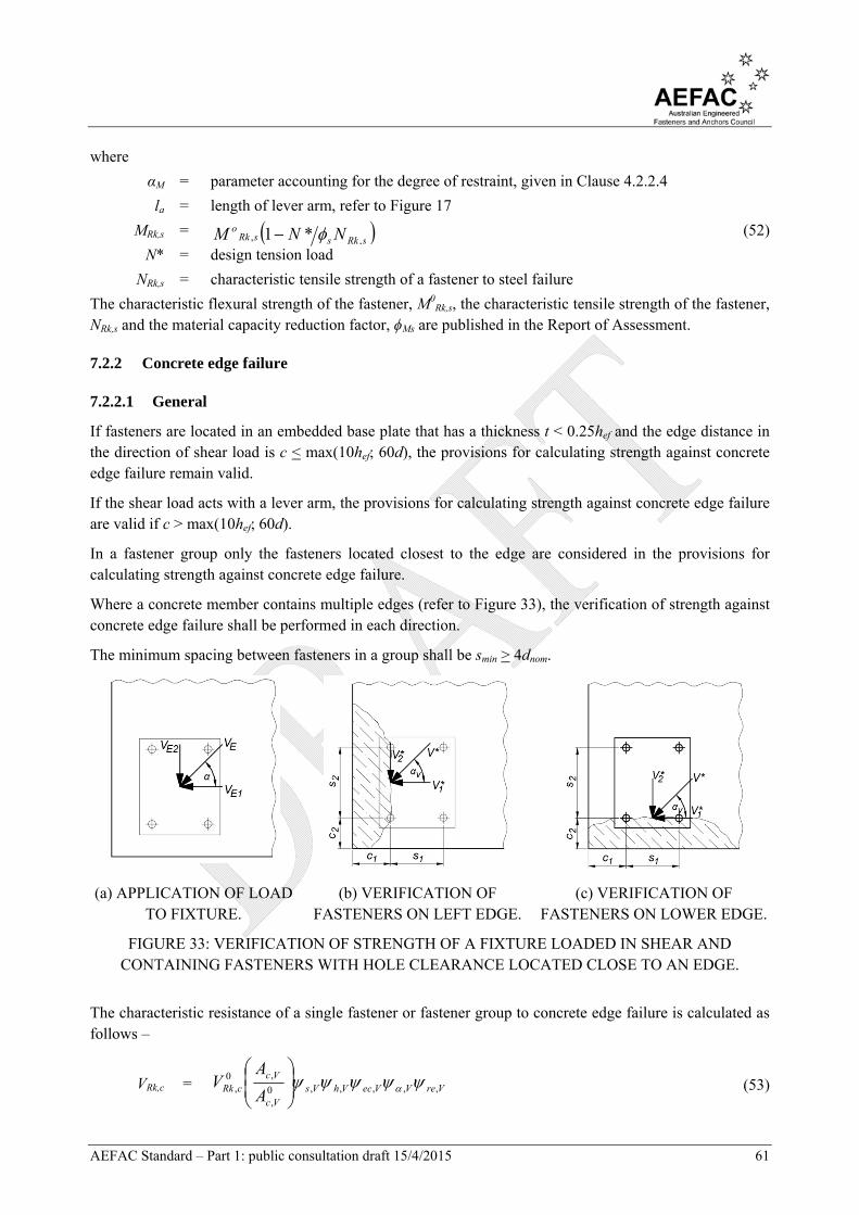
AEFAC Standard – Part 1: public consultation draft 15/4/2015 61
where
αM = parameter accounting for the degree of restraint, given in Clause 4.2.2.4
la = length of lever arm, refer to Figure 17
MRk,s = sRkssRko NNM ,, *1 (52)
N* = design tension load
NRk,s = characteristic tensile strength of a fastener to steel failure
The characteristic flexural strength of the fastener, M0Rk,s, the characteristic tensile strength of the fastener,
NRk,s and the material capacity reduction factor, ϕMs are published in the Report of Assessment.
7.2.2 Concrete edge failure
7.2.2.1 General
If fasteners are located in an embedded base plate that has a thickness t < 0.25hef and the edge distance in the direction of shear load is c < max(10hef; 60d), the provisions for calculating strength against concrete edge failure remain valid.
If the shear load acts with a lever arm, the provisions for calculating strength against concrete edge failure are valid if c > max(10hef; 60d).
In a fastener group only the fasteners located closest to the edge are considered in the provisions for calculating strength against concrete edge failure.
Where a concrete member contains multiple edges (refer to Figure 33), the verification of strength against concrete edge failure shall be performed in each direction.
The minimum spacing between fasteners in a group shall be smin > 4dnom.
(a) APPLICATION OF LOAD TO FIXTURE.
(b) VERIFICATION OF FASTENERS ON LEFT EDGE.
(c) VERIFICATION OF FASTENERS ON LOWER EDGE.
FIGURE 33: VERIFICATION OF STRENGTH OF A FIXTURE LOADED IN SHEAR AND CONTAINING FASTENERS WITH HOLE CLEARANCE LOCATED CLOSE TO AN EDGE.
The characteristic resistance of a single fastener or fastener group to concrete edge failure is calculated as follows –
VRk,c = VreVVecVhVsVc
VccRk A
AV ,,,,,0
,
,0,
(53)

AEFAC Standard – Part 1: public consultation draft 15/4/2015 62
where
V0Rk,c = initial value of the characteristic shear strength of the fastener, given
in Clause 7.2.2.2
Ac,V = actual area of idealised concrete break-out body, given in Clause 7.2.2.3
A0c,V = reference projected area of failure cone, given in Clause 7.2.2.3
ψs,V = parameter accounting for the disturbance to the distribution of stresses in the concrete member, given in Clause 7.2.2.4
ψh,V = parameter accounting for the influence of member thickness, given in Clause 7.2.2.5
ψec,V = parameter accounting for the eccentricity of the resultant load in a fastener group, given in Clause 7.2.2.6
ψα,V = parameter accounting for the angle of the applied load, given in Clause 7.2.2.7
ψre,V = parameter accounting for the shell spalling effect, given in Clause 7.2.2.8
7.2.2.2 Basic characteristic shear strength
The basic characteristic shear strength of a single fastener loaded perpendicular to the edge of the concrete member is calculated as follows –
V0Rk,c =
5.115 ' cfldk cfnom
(54)
where
k5 = parameter accounting for the state of the concrete
= 1.7 for cracked concrete
= 2.4 for non-cracked concrete
dnom = outside diameter of fastener, published in the Report of Assessment
α =
5.0
1
1.0
c
l f (55)
β = 2.0
1
1.0
c
dnom (56)
lf = parameter related to the length of the fastener, published in the Report of Assessment
= hef for headed fasteners with a uniform shank diameter and post-installed fastener with a uniform diameter
< 12dnom where dnom < 24 mm
< max(8dnom, 300 mm) where dnom > 24 mm
< 60 mm
f’c = characteristic compressive strength of concrete
c1 = edge distance of fastener
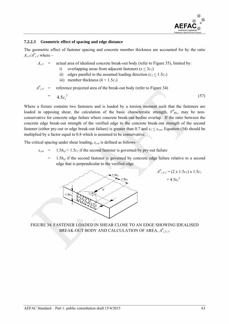
AEFAC Standard – Part 1: public consultation draft 15/4/2015 63
7.2.2.3 Geometric effect of spacing and edge distance
The geometric effect of fastener spacing and concrete member thickness are accounted for by the ratio Ac,V/A0
c,V where –
Ac,V = actual area of idealised concrete break-out body (refer to Figure 35), limited by: i) overlapping areas from adjacent fasteners (s < 3c1) ii) edges parallel to the assumed loading direction (c2 < 1.5c1) iii) member thickness (h < 1.5c1)
A0c,V = reference projected area of the break-out body (refer to Figure 34)
= 215.4 c (57)
Where a fixture contains two fasteners and is loaded by a torsion moment such that the fasteners are loaded in opposing shear, the calculation of the basic characteristic strength, V0
Rk,c may be non-conservative for concrete edge failure where concrete break-out bodies overlap. If the ratio between the concrete edge break-out strength of the verified edge to the concrete break-out strength of the second fastener (either pry-out or edge break-out failure) is greater than 0.7 and s2 < scrit, Equation (54) should be multiplied by a factor equal to 0.8 which is assumed to be conservative.
The critical spacing under shear loading, scrit is defined as follows –
scrit = 1.5hef + 1.5c1 if the second fastener is governed by pry-out failure
= 1.5hef if the second fastener is governed by concrete edge failure relative to a second edge that is perpendicular to the verified edge
A0c,V,1 = (2 x 1.5c1) x 1.5c1
= 4.5c12
FIGURE 34: FASTENER LOADED IN SHEAR CLOSE TO AN EDGE SHOWING IDEALISED BREAK-OUT BODY AND CALCULATION OF AREA, A0
c,V,1.
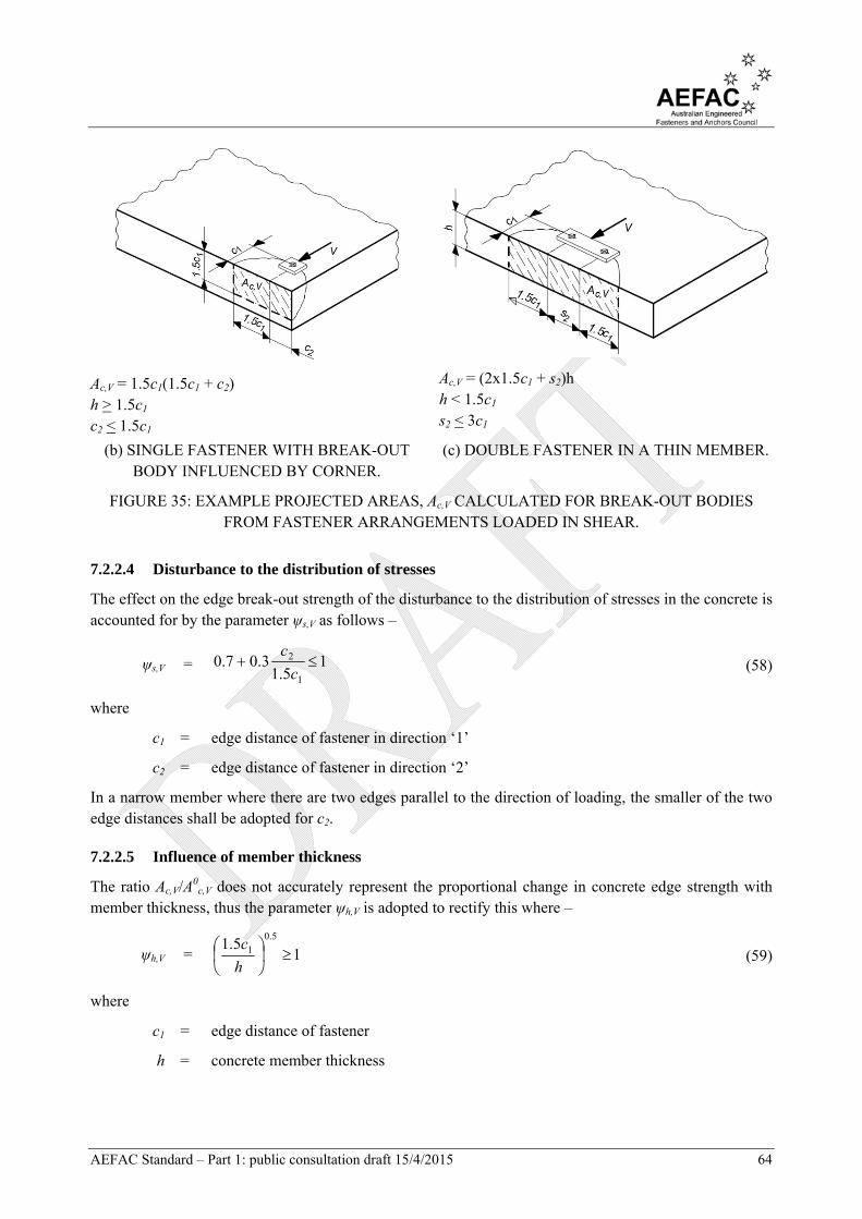
AEFAC Standard – Part 1: public consultation draft 15/4/2015 64
Ac,V = 1.5c1(1.5c1 + c2) h > 1.5c1 c2 < 1.5c1
Ac,V = (2x1.5c1 + s2)h h < 1.5c1 s2 < 3c1
(b) SINGLE FASTENER WITH BREAK-OUT BODY INFLUENCED BY CORNER.
(c) DOUBLE FASTENER IN A THIN MEMBER.
FIGURE 35: EXAMPLE PROJECTED AREAS, Ac,V CALCULATED FOR BREAK-OUT BODIES FROM FASTENER ARRANGEMENTS LOADED IN SHEAR.
7.2.2.4 Disturbance to the distribution of stresses
The effect on the edge break-out strength of the disturbance to the distribution of stresses in the concrete is accounted for by the parameter ψs,V as follows –
ψs,V = 15.1
3.07.01
2 c
c (58)
where
c1 = edge distance of fastener in direction ‘1’
c2 = edge distance of fastener in direction ‘2’
In a narrow member where there are two edges parallel to the direction of loading, the smaller of the two edge distances shall be adopted for c2.
7.2.2.5 Influence of member thickness
The ratio Ac,V/A0c,V does not accurately represent the proportional change in concrete edge strength with
member thickness, thus the parameter ψh,V is adopted to rectify this where –
ψh,V = 15.1
5.01
h
c (59)
where
c1 = edge distance of fastener
h = concrete member thickness

AEFAC Standard – Part 1: public consultation draft 15/4/2015 65
7.2.2.6 Eccentricity of loading on a fastener group
The parameter ψec,V accounts for a group effect when there is different shear loads resisted by individual fasteners in the group as follows –
ψec,V = 13/.21
1
1
ceV
(60)
where
eV = eccentricity of the resultant shear force acting on a group of fasteners relative to the centre of gravity of the fasteners loaded in shear (refer to Figure 36)
c1 = edge distance of fastener
FIGURE 36: FIXTURE THAT HAS A SHEAR LOAD, VEd THAT HAS BEEN LOADED ECCENTRICALLY BY AN AMOUNT EQUAL TO eV.
7.2.2.7 Direction of loading
The parameter ψα,V accounts for the influence on edge break-out strength of the shear load applied at an angle to the free edge under consideration and shall be calculated as –
ψα,V = 1
sin5.0cos
122
VV (61)
where
αV = angle between the applied load to the fastener or fastener group and the direction perpendicular to the free edge under consideration, 0 < αV < 90o
7.2.2.8 Edge reinforcement
The influence of edge reinforcement on the edge break-out strength is accounted for by the parameter ψre,V as follows –
ψre,V = 1.0 for fasteners in cracked concrete without edge reinforcement or stirrups or in non-cracked concrete
= 1.4 for fasteners in cracked concrete containing edge reinforcement that includes stirrups or wire mesh with spacing a < 100 mm and a < 2c1. This factor may only be applied if the effective embedment depth, hef is at least equal to 2.5 times the cover of the edge reinforcement.

AEFAC Standard – Part 1: public consultation draft 15/4/2015 66
7.2.2.9 Narrow concrete member
For a narrow member, c2,max < 1.5c1 that is also deemed to be thin, h < 1.5c1, Equation (53) provides a conservative estimation of the edge break-out strength, VRk,c. A more precise calculation of VRk,c is achieved by substituting c’1 for c1 (refer to Figure 37) in Equations (54) – (60) including for the determination of Ac,V and A0
c,V, where –
c'1 = 5.1,5.1max max,2 hc for single fasteners (62)
= 3,5.1,5.1max max,max,2 cshc for fastener groups (63)
where
c2,max = largest of the two edge distances parallel to the direction of loading in the case of a single fastener
s2,max = maximum spacing between fasteners in a group in direction ‘2’
(a) SINGLE FASTENER. (b) MULTIPLE FASTENERS.
max(c2,1 and c2,2) < 1.5c1 and h < 1.5c1
(c) CROSS-SECTION VIEW OF FASTENER(S).
FIGURE 37: FASTENERS LOCATED IN THIN CONCRETE MEMBERS LOADED IN SHEAR SHOWING BREAK-OUT BODY AND REVISED BREAK-OUT BODY BASED ON THE REVISED
EDGE DISTANCE, c’1.
7.2.3 Concrete pry-out failure
Verification of the strength of the fastener or fastener group against concrete pry-out failure includes pry-out failure on the side opposite to the direction of loading, as well as a tension force that may be induced in the fastener as a result of shear loading.
The characteristic strength of a headed or mechanical post-installed fastener to pry-out failure is calculated as follows –
VRk,cp = k3NRk,c for fastenings without supplementary reinforcement (64)
= 0.75k3NRk,c for fastenings with supplementary reinforcement (65)

AEFAC Standard – Part 1: public consultation draft 15/4/2015 67
where
k3 = parameter published in the Report of Assessment
NRk,c = characteristic concrete cone strength for a single fastener or fastener in a group, determined in accordance with Clause 6.3.2
The characteristic strength of a bonded post-installed fastener to pry-out failure is calculated as follows –
VRk,cp = k3min(NRk,c, NRk,p) for fastenings without supplementary reinforcement (66)
= 0.75k3min(NRk,c, NRk,p) for fastenings with supplementary reinforcement
(67)
where
NRk,p = characteristic strength against pull-out failure for a single fastener or all fasteners in a group loaded in shear, determined in accordance with Clause 6.2.3
Where multiple fasteners are present in a group and opposing shear forces are applied, such as the condition where a torsion moment is applied, the most adverse condition shall be verified.
The determination of Ac,N shall include a virtual edge equal to 0.5s in the direction of the neighbouring fastener(s) (refer to Figure 38).
(a) (b)
FIGURE 38: GROUP OF FASTENERS LOADED IN SHEAR SHOWING THE CALCULATION OF THE AREA, Ac,N FOR PRY-OUT FAILURE DUE TO THE SHEAR COMPONENT OF THE LOAD
ACTING ON ONE OF THE FASTENERS IN THE GROUP, ASSUMING scr,N = 3hef.
7.2.4 Supplementary reinforcement
Should the fastener design include provision for supplementary reinforcement, Clause 6.2.7 shall be followed.

AEFAC Standard – Part 1: public consultation draft 15/4/2015 68
7.3 CAST-IN ANCHOR CHANNEL
The verifications in Table 5 shall apply.
7.3.1 Steel failure
The presence of a lever arm for the purpose of design for shear load is determined in accordance with Clause 4.2.2.3 and Clause 4.2.2.4.
7.3.1.1 General
The following strengths are published in the Report of Assessment –
(a) Characteristic shear strength of anchor against steel fracture, VRk,s,a (b) Characteristic shear strength of anchor against failure of the connection between anchor and
channel, VRk,s,c (c) Basic characteristic shear strength of anchor against local failure by flexure of the channel lips,
V0Rk,s,l
(d) Characteristic shear strength of channel bolt, VRk,s (e) Characteristic flexural strength of an anchor channel, MRk,s,flex
7.3.1.2 Flexural failure of channel lips
The characteristic strength against flexural failure of the channel lips shall be calculated as follows –
VRk,s,l = VllsRkV ,,,0 (68)
where
ψl,V = 115.0,
Vl
cbo
s
s
scbo = actual spacing of anchor channel bolts
sl,V = characteristic spacing for channel lip failure under shear loading, published in the Report of Assessment. A value of sl,V = 2bch may be adopted if no further guidance is available.
7.3.1.3 Shear force with lever arm
Where the fastener is considered to include a lever arm (refer to Clause 4.2.2.3) the characteristic steel shear strength, VRk,s,M shall be calculated in accordance with Clause 7.2.1.2.
The Report of Assessment includes information addressing the influence of a shear load with lever arm on channel lip failure.
7.3.2 Concrete edge failure
7.3.2.1 General
The strength against concrete edge failure, VRk,c may be calculated as follows –
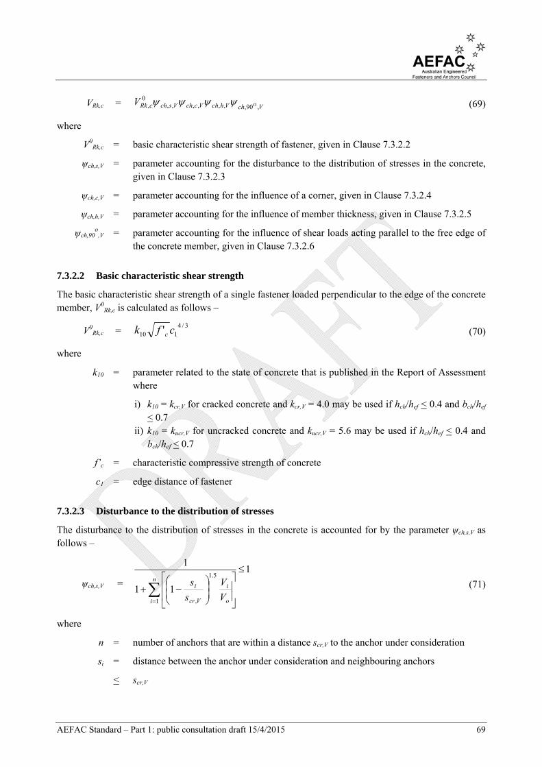
AEFAC Standard – Part 1: public consultation draft 15/4/2015 69
VRk,c = VchVhchVcchVschcRk OV,90,,,,,,,
0, (69)
where
V0Rk,c = basic characteristic shear strength of fastener, given in Clause 7.3.2.2
ψch,s,V = parameter accounting for the disturbance to the distribution of stresses in the concrete, given in Clause 7.3.2.3
ψch,c,V = parameter accounting for the influence of a corner, given in Clause 7.3.2.4
ψch,h,V = parameter accounting for the influence of member thickness, given in Clause 7.3.2.5
ψch,90o
,V = parameter accounting for the influence of shear loads acting parallel to the free edge of the concrete member, given in Clause 7.3.2.6
7.3.2.2 Basic characteristic shear strength
The basic characteristic shear strength of a single fastener loaded perpendicular to the edge of the concrete member, V0
Rk,c is calculated as follows –
V0Rk,c =
3/4110 ' cfk c (70)
where
k10 = parameter related to the state of concrete that is published in the Report of Assessment where
i) k10 = kcr,V for cracked concrete and kcr,V = 4.0 may be used if hch/hef < 0.4 and bch/hef < 0.7
ii) k10 = kucr,V for uncracked concrete and kucr,V = 5.6 may be used if hch/hef < 0.4 and bch/hef < 0.7
f’c = characteristic compressive strength of concrete
c1 = edge distance of fastener
7.3.2.3 Disturbance to the distribution of stresses
The disturbance to the distribution of stresses in the concrete is accounted for by the parameter ψch,s,V as follows –
ψch,s,V =
1
11
1
1
5.1
,
n
i o
i
Vcr
i
V
V
s
s
(71)
where
n = number of anchors that are within a distance scr,V to the anchor under consideration
si = distance between the anchor under consideration and neighbouring anchors
< scr,V
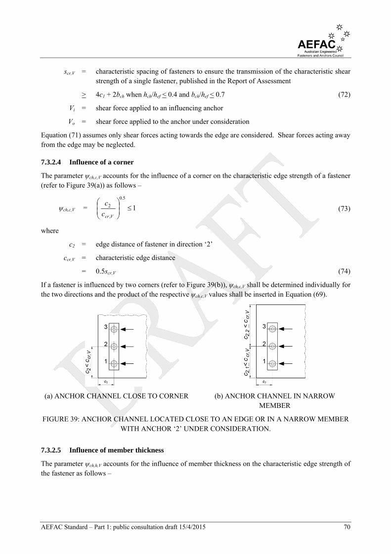
AEFAC Standard – Part 1: public consultation draft 15/4/2015 70
scr,V = characteristic spacing of fasteners to ensure the transmission of the characteristic shear strength of a single fastener, published in the Report of Assessment
> 4c1 + 2bch when hch/hef < 0.4 and bch/hef < 0.7 (72)
Vi = shear force applied to an influencing anchor
Vo = shear force applied to the anchor under consideration
Equation (71) assumes only shear forces acting towards the edge are considered. Shear forces acting away from the edge may be neglected.
7.3.2.4 Influence of a corner
The parameter ψch,c,V accounts for the influence of a corner on the characteristic edge strength of a fastener (refer to Figure 39(a)) as follows –
ψch,c,V = 1
5.0
,
2
Vcrc
c (73)
where
c2 = edge distance of fastener in direction ‘2’
ccr,V = characteristic edge distance
= 0.5scr,V (74)
If a fastener is influenced by two corners (refer to Figure 39(b)), ψch,c,V shall be determined individually for the two directions and the product of the respective ψch,c,V values shall be inserted in Equation (69).
(a) ANCHOR CHANNEL CLOSE TO CORNER (b) ANCHOR CHANNEL IN NARROW MEMBER
FIGURE 39: ANCHOR CHANNEL LOCATED CLOSE TO AN EDGE OR IN A NARROW MEMBER WITH ANCHOR ‘2’ UNDER CONSIDERATION.
7.3.2.5 Influence of member thickness
The parameter ψch,h,V accounts for the influence of member thickness on the characteristic edge strength of the fastener as follows –

AEFAC Standard – Part 1: public consultation draft 15/4/2015 71
ψch,h,V = 1
5.0
,
Vcrh
h (75)
where
h = member thickness when hch/hef < 0.4 and bch/hef < 0.7
hcr,V = characteristic member thickness for a fastener taken from the Report of Assessment
> 2c1 + 2hch (refer to Figure 40) where hch/hef < 0.4 and bch/hef < 0.7 (76)
FIGURE 40: EXAMPLE OF THE SHEAR RESISTANCE OF ANCHOR CHANNEL INFLUENCED BY CONCRETE MEMBER THICKNESS.
7.3.2.6 Direction of loading
The parameter ψch,90o
,V accounts for the presence of a shear load acting parallel to the edge (refer to Figure 41) such that –
ψch,90o
,V = 2.5 (77)
FIGURE 41: EXAMPLE OF ANCHOR CHANNEL LOADED IN SHEAR PARALLEL TO THE EDGE OF THE CONCRETE MEMBER.
7.3.2.7 Narrow concrete member
For a narrow member, c2,max < ccr,V (refer to Equation (74)) that is also deemed to be thin, h < hcr,V (refer to Equation (76)), Equation (69) provides a conservative estimation of the concrete edge strength, VRk,c. A more precise calculation of VRk,c is achieved by substituting c’1 for c1 in Equations (70), (72), and (76) (also refer to Figure 42). The value of c’1 may be calculated as follows –
c’1 = max((c2,max – bch)/2, (h – 2hch)/2) (78)
where
c2,max = greatest edge distance parallel to the direction of the applied load
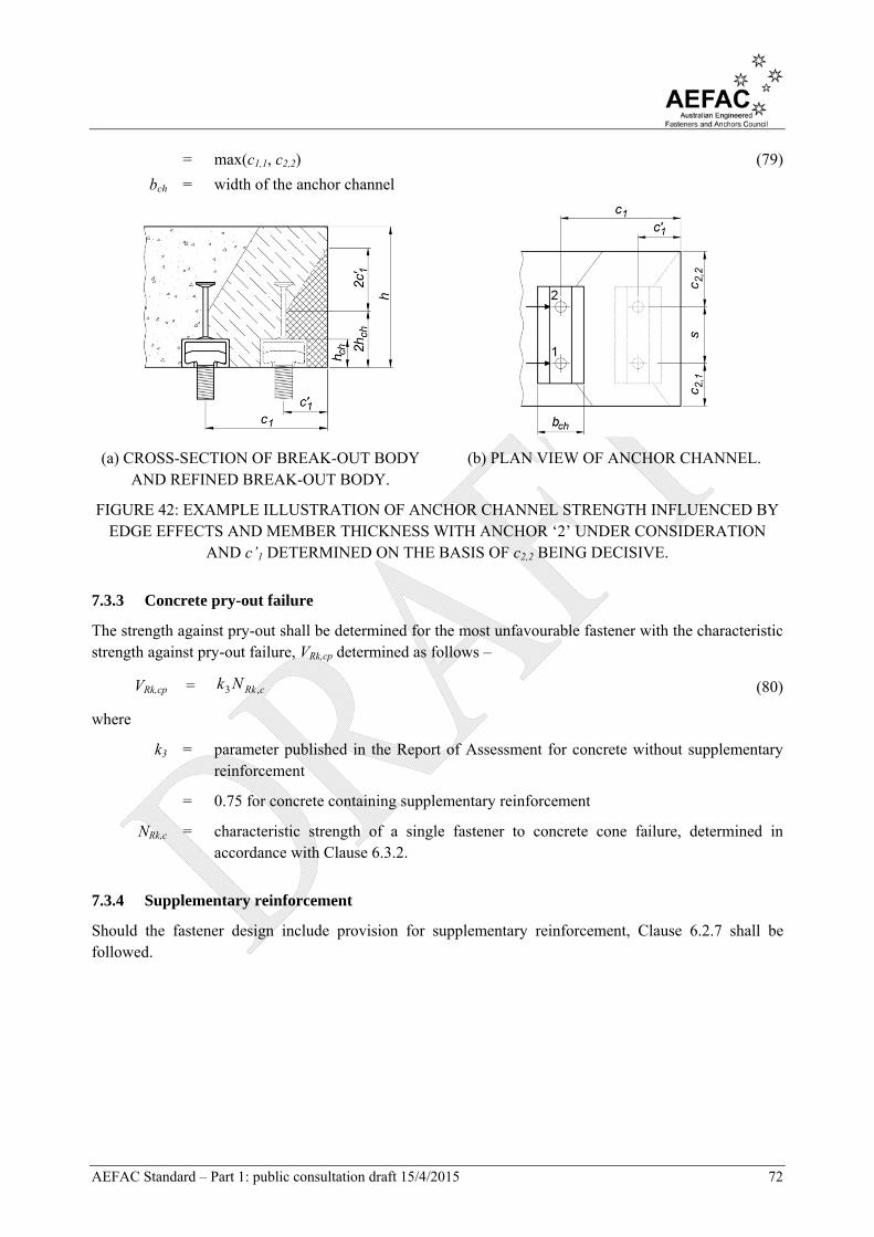
AEFAC Standard – Part 1: public consultation draft 15/4/2015 72
= max(c1,1, c2,2) (79)
bch = width of the anchor channel
(a) CROSS-SECTION OF BREAK-OUT BODY AND REFINED BREAK-OUT BODY.
(b) PLAN VIEW OF ANCHOR CHANNEL.
FIGURE 42: EXAMPLE ILLUSTRATION OF ANCHOR CHANNEL STRENGTH INFLUENCED BY EDGE EFFECTS AND MEMBER THICKNESS WITH ANCHOR ‘2’ UNDER CONSIDERATION
AND c’1 DETERMINED ON THE BASIS OF c2,2 BEING DECISIVE.
7.3.3 Concrete pry-out failure
The strength against pry-out shall be determined for the most unfavourable fastener with the characteristic strength against pry-out failure, VRk,cp determined as follows –
VRk,cp = cRkNk ,3 (80)
where
k3 = parameter published in the Report of Assessment for concrete without supplementary reinforcement
= 0.75 for concrete containing supplementary reinforcement
NRk,c = characteristic strength of a single fastener to concrete cone failure, determined in accordance with Clause 6.3.2.
7.3.4 Supplementary reinforcement
Should the fastener design include provision for supplementary reinforcement, Clause 6.2.7 shall be followed.

AEFAC Standard – Part 1: public consultation draft 15/4/2015 73
8 D E S I G N F O R C O M B I N E D T E N S I O N A N D S H E A R L O A D I N G
8.1 STEEL FAILURE
8.1.1 Post-installed fasteners and cast-in headed fasteners
An assessment of the performance under combined tension and shear loading of the fastener should be performed in accordance with AS 4100 based upon characteristic strength of the headed fastener or post-installed fastener published in the Report of Assessment.
8.1.2 Cast-in Anchor channel
8.1.2.1 Steel failure of the channel bolt
An assessment of the performance under combined tension and shear loading of the channel bolt should be performed in accordance with AS 4100 based upon characteristic strength of the channel bolt published in the Report of Assessment.
8.1.2.2 Anchor channel without supplementary reinforcement
8.1.2.2.1 Channel lip and flexural failure of channel
Verification of the steel failure modes including channel lip and flexural failure of the channel is calculated according to the following equation –
1**
;*
max7171
,,,,,.,,.
k
lsRkls
cb
k
flexsRkflexMs
ch
lsRkls
cb
V
V
M
M
N
N
(81)
where
Ncb* = design tensile load acting on one channel bolt in the anchor channel
Mch* = design bending moment experienced by anchor channel due to the application of design tensile load, Nch*
Vcb* = design shear load acting on one channel bolt in the anchor channel
NRk,s,l = characteristic tensile strength for local flexural failure of channel lips
MRk,s,flex = characteristic flexural strength of anchor channel
VRk,s,l = characteristic shear strength for local flexural failure of channel lip
ϕs.l = capacity reduction factor for steel failure of anchor channel
ϕMs.flex = capacity reduction factor for steel failure of channel in flexure
k71 = parameter to be taken from the Report of Assessment if (ϕs.lVRk,s,l) > (ϕs.lNRk,s,l)
= 2.0 if (ϕs.lVRk,s,l) < (ϕs.lNRk,s,l)
= 1.0 as a simplification

AEFAC Standard – Part 1: public consultation draft 15/4/2015 74
8.1.2.3 Anchor and anchor-channel connection modes of failure
Verification of the steel failure modes including fracture of the anchor and fracture of the connection between the anchor and channel is performed according to the following equation –
1**
;*
max7272
,,.,,.,,.
k
asRkls
a
k
csRkls
a
asRkls
a
V
V
N
N
N
N
(82)
where
Na* = design tensile load acting on one anchor in the anchor channel
Va* = design shear load acting on one anchor in anchor channel
NRk,s,a = characteristic tensile strength of one anchor in anchor channel to steel fracture
NRk,s,c = characteristic tensile strength of anchor-channel connection
VRk,s,a = design shear strength of one anchor in anchor channel to steel fracture
ϕs.l = capacity reduction factor for steel failure of anchor channel
k72 = parameter to be taken from the Report of Assessment if (ϕs.lVRk,s,a) > min(ϕs.lNRk,s,a, ϕs.lNRd,s,c)
= 2.0 if ϕs.lVRk,s,a < min(ϕs.lNRk,s,a, ϕs.lNRk,s,c)
= 1.0 as a simplification
8.2 FAILURE MODES OTHER THAN STEEL
8.2.1 Post-installed mechanical and chemical fasteners and cast-in headed fasteners
A fastener required to resist the design shear, V* and the design tension, N* simultaneously shall satisfy either of the following –
1**
5.1
,
5.1
,
iRkiiRki V
V
N
N
(83)
or
2.1
**
,,
iRkiiRki V
V
N
N
(84)
where
N*/(ϕiNRk,i) < 1 and V*/(ϕiVRk,i) < 1
N* = design tension force applied to a single fastener or group
V* = design shear force applied to a single fastener or group
NRk,i = characteristic tensile strength of fastener or group to failure mode ‘i’
VRk,i = characteristic shear strength of fastener or group to failure mode ‘i’
ϕi = capacity reduction factor for strength of fastener for failure mode ‘i’
AEFAC Standard – Part 1: public consultation draft 15/4/2015 75
The largest value of N*/(ϕiNRk,i) and V*/(ϕiVRk,i) from the different failure modes shall be adopted in Equation (83) or (84).
If the design of the fastening includes supplementary reinforcement, N*/(ϕiNRk,i) for concrete cone failure and V*/(ϕiVRk,i) for concrete edge failure are omitted and replaced by failure of supplementary reinforcement as per Clause 8.3.1.
8.2.2 Cast-in Anchor channel
An anchor channel required to resist the design shear, V* and the design tension, N* simultaneously shall satisfy either Equation (85) or (86) whereby –
1
**5.1
,
5.1
,
iRki
a
iRki
a
V
V
N
N
(85)
or
2.1
**
,,
iRki
a
iRki
a
V
V
N
N
(86)
N*/NRk,i < 1
V*/VRk,i < 1
The largest value of N*/ϕiNRk,i and V*/ϕiVRk,i from the different failure modes shall be adopted in Equation (85) or (86).
8.3 ADDITIONAL VERIFICATION FOR FASTENERS WITH SUPPLEMENTARY REINFORCEMENT
8.3.1 Post-installed fasteners and cast-in headed fasteners
In addition to the requirements of Clause 8.2.1, post-installed fasteners and cast-in headed fasteners with supplementary reinforcement to resist either tension or shear loads only, the following verification shall be made with the largest value of N*/ϕiNRk,i and V*/ϕiVRk,i for the modes of failure other than steel failure –
1**
77
,,
k
iRki
k
iRki V
V
N
N
(87)
where
N*/ϕiNRk,i and V*/ϕiVRk,i < 1
N* = design tension force applied to a single fastener or group
V* = design shear force applied to a single fastener or group
NRk,i = characteristic tensile strength of fastener for each failure mode including NRk,p, NRk,sp, NRk,cb, NRk,re and NRk,a, as well as NRk,c if supplementary reinforcement resists shear loads only
VRk,i = design shear strength of fastener for each failure mode including VRk,c and VRk,cp

AEFAC Standard – Part 1: public consultation draft 15/4/2015 76
ϕi = capacity reduction factor for strength of fastener for failure mode ‘i’
k7 = parameter published in the Report of Assessment that may be conservatively taken as k7 = 2/3
If supplementary reinforcement is included to resist shear loads only, NRk,i includes NRk,c, NRk,p, NRk,sp and NRk,cb, and VRk,i includes VRk,cp, NRk,re and NRk,a.
8.3.2 Cast-in anchor channel
An anchor channel design including supplementary reinforcement to resist tension and shear loads requires verification for the following failure modes:
- Steel failure of the channel bolt, refer to Clause 8.1.2.1 - Other steel failure modes, refer to Clause 8.1.2.2 - Failure modes other than steel, refer to Clause 8.2.2, except N*/(ϕiNRk,i) for concrete cone failure
and V*/(ϕiVRk,i) for concrete edge failure are replaced by failure of supplementary reinforcement outlined below.
In addition to the above verifications, anchor channel located close to an edge with supplementary reinforcement included to resist shear loads, the following verification shall be made –
1
**
,,
iRki
a
iRki
a
V
V
N
N
(88)
where
Na* = design tensile load acting on one anchor in the anchor channel
Va* = design shear load acting on one anchor in the anchor channel
NRk,i = characteristic tensile strength of a single anchor in the anchor channel
VRk,i = characteristic shear strength of a single anchor in the anchor channel
ϕi = capacity reduction factor for failure of fastener for mode ‘i’
If supplementary reinforcement is included to resist tension loads only, NRk,i includes NRk,p, NRk,sp, NRk,re, NRk,cb and NRk,a and VRk,i includes VRk,cp, NRk,re and NRk,a.
AEFAC Standard – Part 1: public consultation draft 15/4/2015 77
9 D E S I G N F O R S E R V I C E A B I L I T Y
9.1 VERIFICATIONS
In order to satisfy serviceability requirements, Clauses 9.2 and 9.3 shall be met.
9.2 DISPLACEMENT
The permissible displacement of the fastener, δd shall be considered. It may be assumed that the system remains linear-elastic such that displacements are directly proportional to the applied load. Displacements under combined tension and shear loading shall be calculated from the vector sum of the tension and shear components of the applied load.
The magnitude of the displacement of the fastener under a given tension or shear load in cracked or uncracked concrete shall be taken from the Report of Assessment.
9.3 LIMITING CRACK WIDTH
Where a fastener system includes supplementary reinforcement, a check shall be performed on the design of the supplementary reinforcement to ensure that detailing requirements of the supplementary reinforcement satisfy limitations on crack width.
AEFAC Standard – Part 1: public consultation draft 15/4/2015 78
1 0 D E S I G N F O R F A T I G U E L O A D I N G
10.1 GENERAL
This part of the Standard addresses design considerations for applications for post-installed fasteners and cast-in headed fasteners subjected to pulsating tension or shear load, alternating shear load, and combinations thereof. Typical applications involving the fatigue loading of fasteners include restraint of cranes, reciprocating machinery, bridge connections, etc.
Verification of fastener strength under fatigue loading shall be performed in accordance with the requirements for static loading (refer to Sections 6, 7 and 8) and fatigue loading (refer to Clause 10.2).
The design for fatigue loading shall ensure the following –
(i) The fastener has prequalification for fatigue loading recognised in the accompanying Report of Assessment.
(ii) A permanent prestress shall be present throughout the design life of the fastener to avoid loosening of the clamping force.
The determination of loads acting on fasteners shall be performed in accordance with Section 4 with the following restrictions –
(i) Fasteners subjected to shear loading and considered to include a lever arm (refer to Clause 4.2.2.4) shall not be permitted.
(ii) Fixtures containing annular gaps shall not be permitted.
10.2 STRENGTH OF FASTENER
The verification for strength of a fastener to fatigue loading shall consider tension loading, shear loading and combined tension and shear loading.
10.2.1 Tension loading
The verifications that shall be considered for fatigue tensile loading of a fastener are included in Table 7.

AEFAC Standard – Part 1: public consultation draft 15/4/2015 79
TABLE 7: VERIFICATIONS REQUIRED FOR TENSILE FATIGUE LOADS APPLIED TO FASTENERS.
Mode of failure Single fastener Fastener group
Most loaded fastener Fastener group
Steel failure fatfatF N,
sRkfatNMs N ,,,
hfatfatF N,
sRkNFfatNMs N ,,,,
Pull-out failure fatfatF N,
pRkfatMp N ,,
hfatfatF N,
pRkNFfatMp N ,,,
Concrete cone failure
fatfatF N,
cRkfatMc N ,,
gfatfatF N,
cRkfatMc N ,,
Concrete splitting failure
fatfatF N,
spRkfatMc N ,,
gfatfatF N,
spRkfatMc N ,,
Blow-out failure fatfatF N,
cbRkfatMc N ,,
gfatfatF N,
cbRkfatMc N ,,
F,fat, Mc,fat, ϕMp fat
= provided in Clause 3.2.4
ϕMs,N,fat = ϕMs,fat in accordance with Clause 3.2.4
ψF,N < 1, factor applied to the tensile strength of the fastener to account for the uneven distribution of loads, provided in the Report of Assessment
ΔNfat = peak-to-peak amplitude of the fatigue tensile action
Nfat,max – Nfat,min
ΔNRk,s = fatigue tensile strength for steel failure provided in the Report of Assessment
ΔNRk,c = fatigue tensile strength for concrete cone failure at 2x10⁶ load cycles
= 0.5NRk,c with NRk,c determined from Equation (7)
ΔNRk,p = fatigue tensile strength for pull-out failure provided in the Report of Assessment
ΔNRk,sp = fatigue tensile strength to splitting failure for 2x10⁶ load cycles
= 0.5NRk,sp with NRk,sp determined from Equation (29)
ΔNRk,cb = fatigue tensile strength to blow-out failure for 2x10⁶ load cycles
= 0.5NRk,cb with NRk,cb determined from Equation (32)

AEFAC Standard – Part 1: public consultation draft 15/4/2015 80
10.2.2 Shear loading
The verifications that shall be considered for fatigue shear loading of a fastener are included in Table 8.
TABLE 8: VERIFICATIONS REQUIRED FOR SHEAR FATIGUE LOADS APPLIED TO FASTENERS.
Mode of failure Single fastener Fastener group
Most loaded fastener Fastener group
Steel failure - without lever arm
fatfatF V,
sRkfatVMs V ,,,
hfatfatF V,
sRkVFfatVMs V ,,,,
Pry-out failure fatfatF V,
cpRkfatMc V ,,
gfatfatF V,
cpRkfatMc V ,,
Edge failure fatfatF V,
cRkfatMc V ,,
gfatfatF V,
cRkfatMc V ,,
F,fat, γMc,fat = provided in Clause 3.2.4
ϕMs,V,fat = ϕMs,fat in accordance with Clause 3.2.4
ψF,V < 1, factor applied to the shear strength of the fastener to account for the uneven distribution of loads, provided in the Report of Assessment
ΔVfat = peak-to-peak amplitude of the fatigue shear action
VEk,max – VEk,min
ΔVRk,s = fatigue shear strength for steel failure provided in the Report of Assessment
ΔVRk,c = fatigue shear strength to concrete cone failure at 2x10⁶ load cycles
= 0.5VRk,c with VRk,c determined from Equation (53)
ΔVRk,cp = fatigue shear strength to concrete pry-out failure provided in the Report of Assessment
= 0.5VRk,cp with VRk,cp determined from Equation (64) or (65)
10.2.3 Combined tension and shear loading
The verification for fatigue combined tension and shear loading shall be performed as follows –
1,, fatVfatN (89)
where
βN,fat = 1,,
,
RkfatMNF
fatfatF
N
N
(90)
βV,fat =
1,,
,
RkfatMVF
fatfatF
V
V
(91)
AEFAC Standard – Part 1: public consultation draft 15/4/2015 81
α = αs for verification of steel failure, given in the Report of Assessment
= αc for verification of modes of failure other than steel, given in the Report of Assessment
ΔNfat, ΔNRk = found in Table 7
ΔVfat, ΔVRk = found in Table 8
From the different modes of failure being considered, the greatest values of βN,fat and βV,fat shall be adopted in Equation (89).

AEFAC Standard – Part 1: public consultation draft 15/4/2015 82
1 1 R E F E R E N C E S
The following normative references have been made in this Standard –
AEFAC Standard Part 2
AS/NZS 1170 Structural design actions
AS/NZS 1170.0 Part 0: General principles
AS/NZS 3678 Structural steel – hot-rolled plates, floorplates and slabs
AS/NZS 4671 Steel reinforcing materials
AS 1379 Specification and supply of concrete
AS 1554.2 Structural steel welding, Part 2: Stud welding (steel studs to steel)
AS 3600 Concrete structures
AS 4291.1 Mechanical properties of fasteners made of carbon steel and alloy steel, Part 1: Bolts, screws and studs
AS 4100 Steel structures
EOTA Technical Report No. 020 “Evaluation of anchorages in concrete concerning resistance to fire”
ETAG 001 Part 1 “Guideline for European Technical Approval of metal anchors for use in concrete, part one: anchors in general”, European Organisation for Technical Approvals, 2nd Amended April 2013
ETAG 001 Part 2 “Guideline for European Technical Approval of metal anchors for use in concrete, part two: torque-controlled expansion anchors”, European Organisation for Technical Approvals, 2nd Amended April 2013
ETAG 001 Part 3 “Guideline for European Technical Approval of metal anchors for use in concrete, part three: undercut anchors”, European Organisation for Technical Approvals, 2nd Amended April 2013
ETAG 001 Part 4 “Guideline for European Technical Approval of metal anchors for use in concrete, part four: deformation-controlled expansion anchors”, European Organisation for Technical Approvals, 2nd Amended April 2013
ETAG 001 Part 5 “Guideline for European Technical Approval of metal anchors for use in concrete, part five: bonded anchors”, European Organisation for Technical Approvals, 3rd Amended April 2013
ETAG 001 Annex A “Guideline for European Technical Approval of metal anchors for use in concrete, Details of test”, European Organisation for Technical Approvals, 2nd Amendment November 2006
ETAG 001 Annex E “Assessment of metal anchors under seismic action”, EOTA, April 2013
Handbook HB 18.67 – 2005 “Conformity assessment – fundamentals of product certification”, Standards Australia
ISO 898-1 Mechanical properties of fasteners made of carbon steel and alloy steel – Part 1: Bolts, screws and studs with specified property classes – coarse thread and fine pitch thread
ISO 898-2 Mechanical properties of fasteners made of carbon steel and alloy steel – Part 2: Nuts with specified property classes – coarse thread and fine pitch thread
ISO 4506 Hardmetals – compression test

AEFAC Standard – Part 1: public consultation draft 15/4/2015 83
ISO 5922 Malleable cast iron
prEN 1992-4:2013 “Eurocode 2: Design of concrete structures – Part 4: Design of Fastenings for Use in Concrete” CEN/TC 250
The following informative references have been made in this Standard –
DIN 8035 Masonry drills – hammer drills with hardmetal tip
ISO 5468 Rotary and rotary impact masonry drill bits with hardmetal tips - dimensions

AEFAC Standard – Part 1: public consultation draft 15/4/2015 84
A P P E N D I X A ( I N F O R M A T I V E ) A S S U M P T I O N S F O R T H E D E S I G N A N D E X E C U T I O N O F F A S T E N E R S
A.1 GENERAL
This Appendix outlines the assumptions in inherent in this Standard with respect to installation and execution of the relative type of fastener and welding design of the headed fasteners. The manufacturer’s installation instructions should support the information provided herein.
A.2 POST-INSTALLED FASTENERS
The concrete is assumed to be correctly compacted in the region designated for fastening and should be checked prior to installation, typically by visual methods.
A number of assumptions are made regarding the drilling operation as follows –
(i) Drilling is performed in accordance with the manufacturer’s installation instructions. (ii) Suitably qualified personnel should perform the drilling. (iii) Drilling is performed perpendicular to the surface of the concrete member unless directed
otherwise in the manufacturer’s installation instructions. (iv) Hammer drill bits adopted should conform to the dimensional requirements of ISO 5468 for drill
bit diameters up to 25 mm and DIN 8035 for drill bit diameters greater than 25 mm but not exceeding 40 mm. A conformity mark to the relevant standard should demonstrate conformity, otherwise evidence of suitability should be demonstrated.
(v) Diamond core drilling should comply with the prescribed hole diameter. (vi) Hole cleaning should be performed in accordance with the manufacturer’s installation
instructions as noted in the Report of Assessment. (vii) Holes that have been aborted (e.g. due to hitting reinforcement) should be filled with a non-
shrink mortar with a strength no less than that of the substrate and at least 40 MPa.
Unless explicit permission has been granted, reinforcement should not be damaged during drilling. Drilling should not be performed closer than 50 mm to the nearest reinforcement. In the event that drilling hits reinforcement, permission should be sought in writing before drilling through the reinforcement.
A.3 CAST-IN HEADED FASTENERS
A quality control system should be in place for welding of headed fasteners to include the following –
(i) A welding procedure consistent with the requirements of AS 1554.2 and additional provisions provided in the Report of Assessment.
(ii) Fastener secured for the placement of the reinforcement and concrete (including compaction) such that no movement will occur.
(iii) Adequate compaction of the concrete achieved in the region of the fasteners, particularly under the fixture and around the head of fasteners. Fixtures with dimensions greater than 400 mm x 400 mm will typically require vent openings that should also have careful compaction.
(iv) An appropriately qualified person inspects and approves that the installation has been performed correctly.
Fasteners may be punched and vibrated into wet concrete immediately after pouring subject to the following provisions –

AEFAC Standard – Part 1: public consultation draft 15/4/2015 85
(i) Proper compaction of concrete is achieved under the head of the fastener or fixture. (ii) The fastener is not moved once vibration has been completed. (iii) All fasteners in a fixture should be inserted simultaneously during vibrating, typically achievable
for fixtures with dimensions 200 mm x 200 mm or less with up to four fasteners.
A.4 ANCHOR CHANNEL
The anchor channel should be secured for the placement of the reinforcement and concrete (including compaction) such that no movement will occur.
Adequate compaction of the concrete should be achieved, particularly under the channel and around the head of the anchors.
An anchor channel should not be inserted into wet concrete (except as noted below).
Anchor channel may be vibrated into wet concrete provided the following conditions are met –
(i) One person should not insert an anchor channel of length greater than one metre. For longer lengths of anchor channel at least two personnel are required.
(ii) The anchor channel should not be moved once vibration has been completed. (iii) Proper compaction of concrete is achieved under the head of anchors and the anchor channel.
Where required, inspection and verification of correct installation should be performed by an appropriately qualified individual.
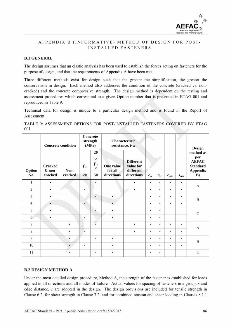
AEFAC Standard – Part 1: public consultation draft 15/4/2015 86
A P P E N D I X B ( I N F O R M A T I V E ) M E T H O D O F D E S I G N F O R P O S T -I N S T A L L E D F A S T E N E R S
B.1 GENERAL
The design assumes that an elastic analysis has been used to establish the forces acting on fasteners for the purpose of design, and that the requirements of Appendix A have been met.
Three different methods exist for design such that the greater the simplification, the greater the conservatism in design. Each method also addresses the condition of the concrete (cracked vs. non-cracked) and the concrete compressive strength. The design method is dependent on the testing and assessment procedures which correspond to a given Option number that is presented in ETAG 001 and reproduced in Table 9.
Technical data for design is unique to a particular design method and is found in the Report of Assessment.
TABLE 9: ASSESSMENT OPTIONS FOR POST-INSTALLED FASTENERS COVERED BY ETAG 001.
Option No.
Concrete condition
Concrete strength (MPa)
Characteristic resistance, FRk
ccr scr cmin smin
Design method as
per AEFAC
Standard Appendix
B)
Cracked & non-cracked
Non-cracked
f’c = 20
20
< f’c <
50
One value for all
directions
Different value for different
directions
1 • • • • • • • A
2 • • • • • • •
3 • • • • • • • B
4 • • • • • • •
5 • • • • • C
6 • • • • •
7 • • • • • • • A
8 • • • • • • •
9 • • • • • • • B
10 • • • • • • •
11 • • • • • C
B.2 DESIGN METHOD A
Under the most detailed design procedure, Method A, the strength of the fastener is established for loads applied in all directions and all modes of failure. Actual values for spacing of fasteners in a group, s and edge distance, c are adopted in the design. The design provisions are included for tensile strength in Clause 6.2, for shear strength in Clause 7.2, and for combined tension and shear loading in Clauses 8.1.1
AEFAC Standard – Part 1: public consultation draft 15/4/2015 87
(steel failure), Clause 8.2.1 (failure modes other than steel) and Clause 8.3.1 (additional verifications for fasteners with supplementary reinforcement).
The data required for design Method A is provided in the Report of Assessment.
B.3 DESIGN METHOD B
Design Method B requires the identification of a single value for basic characteristic strength, F0Rk for a
given concrete compressive strength and that is adopted for all load directions and all modes of failure.
B.3.1 Basic design strength
The characteristic values for spacing, scr and edge distance, ccr are adopted such that the design becomes –
S* < ϕMF0Rk (92)
where
S* = design action effect (refer to Equation (1))
ϕM = capacity reduction factor for material
F0Rk = basic characteristic strength of fastener
B.3.2 Characteristic strength with reduced spacing or edge distance
If the spacing and edge distance are less than the characteristic value (s < scr and c < ccr) the characteristic strength is calculated as follows –
FRk = cresc
cRk
A
A
n
F
0
0
(93)
where
F0Rk = basic characteristic strength of fastener
n = number of loaded fasteners
Ac = actual projected area of the failure cone of the fastener, calculated in accordance with Clause 6.2.2.1 by replacing Ac,N with Ac.
A0c = reference projected area of the failure cone of the fastener, calculated according to
Clause 6.2.2.1 by replacing A0c,N, scr,N and ccr,N with A0
c, scr and ccr, respectively.
ψs = parameter related to the distribution of stresses in the concrete due to the proximity of the fastener to an edge, calculated in accordance with Clause 6.2.2.4 and replacing ccr,N with ccr.
ψre = parameter accounting for the shell spalling factor, calculated according to Clause 6.2.2.5
ψc = parameter accounting for the influence of the concrete compressive strength on the strength of the fastener provided in the Report of Assessment.
B.3.3 Additional provisions
Additional provisions for fastener design using Method B include –
(i) The greatest design load on a fastener in a group should not exceed the value calculated by Equation (93).

AEFAC Standard – Part 1: public consultation draft 15/4/2015 88
(ii) For a fastener loaded in shear that has a lever arm, the characteristic shear strength, VRk,s,M should be calculated according to Clause 7.2.1.2, replacing NRk,s with F0
Rk. (iii) The design shear strength shall not exceed FRk calculated from Equation (93) (VRk,s < FRk). (iv) The basic characteristic strength for bonded anchors, F0
Rk should be multiplied by the factor accounting for the effects of sustained loading on bond strength, ψsus as defined in Clause 6.2.4.2.
The Report of Assessment includes values for cmin, ccr, scr, smin, F0
Rk, M0
Rk,s, ϕM, ϕMs and ψc.
B.4 DESIGN METHOD C
The design with the greatest simplification, Method C requires the calculation of a single value for the characteristic strength, F0
Rk that is based on the characteristic spacing (scr) and edge distance (ccr). The actual values of spacing and edge distance adopted in the design should not be less than their characteristic values (i.e. s > scr and c > ccr). The design strength is calculated as follows –
S* < ϕMF0Rk
where
ϕM = capacity reduction factor for material
F0Rk = basic characteristic strength of fastener
Additional provisions include –
(i) For a fastener loaded in shear that has a lever arm, the characteristic shear strength, VRk,s,M should be calculated according to Clause 7.2.1.2, replacing NRk,s with FRk.
(ii) The design shear strength (without a lever arm) should not exceed F0Rk (VRk,s < FRk).
(iii) The basic characteristic strength for bonded anchors, F0Rk should be multiplied by the factor
accounting for the effects of sustained loading on bond strength, ψsus as defined in Clause 6.2.4.2.
AEFAC Standard – Part 1: public consultation draft 15/4/2015 89
A P P E N D I X C ( N O R M A T I V E ) V E R I F I C A T I O N O F R E S I S T A N C E O F C O N C R E T E E L E M E N T S T O L O A D S A P P L I E D B Y F A S T E N E R S
C.1 GENERAL
This appendix provides additional design procedures to ensure the safe transmission of fastener loads to the concrete member under ultimate limit state and serviceability limit state loading. The provisions provided herein are intended as an addition to the requirements of AS 3600 for the design for shear strength of a concrete member, including the transmission of fastener loads to the supports.
When a fastener is installed in a composite member comprising a precast element with a structural topping, it assumed that the load is applied to the entire member under the following conditions –
(i) Adequate shear reinforcement is provided between the topping and precast member when the fastener is installed only in the precast member, or
(ii) The effective embedment depth, hef is limited to the depth of the fastener embedded in the topping.
C.2 LIGHTLY LOADED APPLICATIONS
The following provisions for the verification of shear strength of the concrete member apply to applications involving fasteners located in the bottom of a precast element with a unit load not exceeding 1 kPa.
It is assumed that fasteners are applied in the tension face of the concrete element.
C.2.1 No additional verification for transmission of loads required
No additional verification for local transmission of loads to the concrete element is required if one of the following conditions is fulfilled –
a) Design actions (including loading on fastener) at the support of the concrete element are less than design shear capacity of concrete member:
V* < ϕVu (94)
where
V* = design shear load at the support of the concrete member including loads imposed by the fastener
ϕ = capacity reduction factor for shear
Vu = shear capacity of concrete element determined in accordance with AS 3600
b) The design tensile load applied to the tensioned fasteners, N* < 30 kN and the spacing of fasteners, a between the outermost fasteners of adjacent groups or between the outermost fasteners of a group and an individual fastener satisfies the following –
a > *N
where
a = spacing between the outermost fasteners of adjacent fastener groups or between the outermost fasteners and an individual fastener (refer to Figure 5)

AEFAC Standard – Part 1: public consultation draft 15/4/2015 90
c) Hanger (supplementary) reinforcement is included in the design to resist the tensile load applied to the fastener which may be additional reinforcement or underutilized existing reinforcement already present in the structure. The hanger reinforcement should enclose tensile reinforcement in the member and be anchored on the opposite side of the concrete member. The distance between the hanger reinforcement and fastener shall be not greater than hef.
d) The effective embedment depth of the fastener, hef exceeds 0.8 times the depth of the member, h as follows –
hef > 0.8h (95)
where
h = Total depth of concrete member
C.2.2 Verification for local transmission of fastener loads required
If none of the conditions in Clause D.2.1 are fulfilled, the shear forces in the concrete member due to loads applied by the fastener, the following condition shall be fulfilled –
V* < 0.4Vu (96)
where
V* = design shear forces in concrete element due to fastener
ϕ = capacity reduction factor
Vu = ultimate shear strength determined in accordance with AS 3600
The fastener loads shall be assumed to act as point loads with a width of application of t1 = a1 + hef and t2 = a2 + hef in orthogonal directions as per Figure 5.
C.2.3 High load applications
If the design load(s) applied to the fixture causes a resultant applied tension load that is greater than 60 kN, then conditions (c) and (d) in Clause D.2.1 shall be complied with.