AUDIO/VIDEO MULTI-CHANNEL RECEIVER VSX … MULTI-CHANNEL RECEIVER II Thank you for buying this...
92
VSX-37TX VSX-36TX Operating Instructions AUDIO/VIDEO MULTI-CHANNEL RECEIVER
Transcript of AUDIO/VIDEO MULTI-CHANNEL RECEIVER VSX … MULTI-CHANNEL RECEIVER II Thank you for buying this...

VSX-37TXVSX-36TX
Operating Instructions
AUDIO/VIDEOMULTI-CHANNEL RECEIVER

II
Thank you for buying this Pioneer product.Please read through these operating instructions soyou will know how to operate your model properly.After you have finished reading the instructions, putthem away in a safe place for future reference.
[For U.S. model]IMPORTANT NOTICEThe serial number for this equipment is located on
the rear panel. Please write this serial number on your
enclosed warranty card and keep it in a secure area.
This is for your security.
WARNING: TO PREVENT FIRE OR SHOCK
HAZARD, DO NOT EXPOSE THIS APPLIANCE TO RAIN
OR MOISTURE.
THE STANDBY/ON BUTTON ISSECONDARY CONNECTED ANDTHEREFORE DOES NOT SEPARATE THEUNIT FROM MAINS POWER IN STANDBYPOSITION.
IMPORTANT
The lightning flash with arrowhead symbol,within an equilateral triangle, is intended toalert the user to the presence of uninsulated"dangerous voltage" within the product'senclosure that may be of sufficient magnitudeto constitute a risk of electric shock to persons.
The exclamation point within an equilateraltriangle is intended to alert the user to thepresence of important operating andmaintenance (servicing) instructions in theliterature accompanying the appliance.
CAUTION:TO PREVENT THE RISK OF ELECTRIC SHOCK,DO NOT REMOVE COVER (OR BACK). NOUSER-SERVICEABLE PARTS INSIDE. REFERSERVICING TO QUALIFIED SERVICEPERSONNEL.
RISK OF ELECTRIC SHOCKDO NOT OPEN
CAUTION
Information to UserAlteration or modifications carried out without appropriate authorization may invalidate the user's right tooperate the equipment.
NOTE: This equipment has been tested and found to comply with the limits for a Class B digital device, pursuantto Part 15 of the FCC Rules. These limits are designed to provide reasonable protection against harmful interfer-ence in a residential installation. This equipment generates, uses, and can radiate radio frequency energy and,if not installed and used in accordance with the instructions, may cause harmful interference to radio commu-nications. However, there is no guarantee that interference will not occur in a particular installation. If thisequipment does cause harmful interference to radio or television reception, which can be determined by turn-ing the equipment off and on, the user is encouraged to try to correct the interference by one or more of thefollowing measures:
– Reorient or relocate the receiving antenna.
– Increase the separation between the equipment and receiver.
– Connect the equipment into an outlet on a circuit different from that to which the receiver is connected.
– Consult the dealer or an experienced radio/TV technician for help.
[For Canadian model]
This Class B digital apparatus complies withCanadian ICES-003.[Pour le modèle Canadien]
Cet appareil numérique de la classe B estconforme à la norme NMB-003 du Canada.
[For Canadian model]
CAUTION: TO PREVENT ELECTRIC SHOCK, DO
NOT USE THIS (POLARIZED) PLUG WITH AN EXTEN-
SION CORD, RECEPTACLE OR OTHER OUTLET UN-
LESS THE BLADES CAN BE FULLY INSERTED TO PRE-
VENT BLADE EXPOSURE.
ATTENTION: POUR PREVENIR LES CHOCS
ELECTRIQUES NE PAS UTILISER CETTE FICHE
POLARISEE AVEC UN PROLONGATEUR, UNE PRISE
DE COURANT OU UNE AUTRE SORTIE DE COURANT,
SAUF SI LES LAMES PEUVENT ETRE INSERESS A
FOND SANS EN LAISSER AUCUNE PARTIE A
DECOUVERT.
ATTENTION: AFIN DE PREVENIR TOUS
RISQUES DE CHOC ELECTRIQUE OU DE DEBUT
D'ENCENDIE, NE PAS EXPOSER CET APPAREIL A
L'HUMIDITE OU A LA PLUIE.
LE BOUTON STANDBY/ON EST RACCORDESECONDAIREMENT ET PAR CONSEQUENTNE SEPARE PAS L’APPAREIL DEL’ALIMENTATION SECTEUR SUR LAPOSITION D’ATTENTE.

III
READ INSTRUCTIONS — All the safetyand operating instructions should beread before the product is operated.
RETAIN INSTRUCTIONS — The safety andoperating instructions should be retainedfor future reference.
HEED WARNINGS — All warnings on theproduct and in the operating instructionsshould be adhered to.
FOLLOW INSTRUCTIONS — All operatingand use instructions should be followed.
CLEANING — Unplug this product from thewall outlet before cleaning. The productshould be cleaned only with a polishingcloth or a soft dry cloth. Never cleanwith furniture wax, benzine, insecticidesor other volatile liquids since they maycorrode the cabinet.
ATTACHMENTS — Do not use attachmentsnot recommended by the productmanufacturer as they may causehazards.
WATER AND MOISTURE — Do not usethis product near water — for example,near a bathtub, wash bowl, kitchen sink,or laundry tub; in a wet basement; ornear a swimming pool; and the like.
ACCESSORIES — Do not place this producton an unstable cart, stand, tripod,bracket, or table. The product may fall,causing serious injury to a child or adult,and serious damage to the product. Useonly with a cart, stand, tripod, bracket,or table recommended by themanufacturer, or sold with the product.Any mounting of the product shouldfollow the manufacturer’s instructions,and should use a mounting accessoryrecommended by the manufacturer.
CART — A product and cart combinationshould be moved with care. Quick stops,excessive force, and uneven surfacesmay cause the product and cartcombination to overturn.
VENTILATION — Slots and openings in thecabinet are provided for ventilation andto ensure reliable operation of theproduct and to protect it fromoverheating, and these openings mustnot be blocked or covered. The openingsshould never be blocked by placing theproduct on a bed, sofa, rug, or othersimilar surface. This product should notbe placed in a built-in installation suchas a bookcase or rack unless properventilation is provided or themanufacturer’s instructions have beenadhered to.
POWER SOURCES — This product shouldbe operated only from the type of powersource indicated on the marking label. Ifyou are not sure of the type of powersupply to your home, consult yourproduct dealer or local power company.
LOCATION – The appliance should be in-stalled in a stable location.
NONUSE PERIODS – The power cord ofthe appliance should be unplugged fromthe outlet when left un-used for a longperiod of time.
GROUNDING OR POLARIZATION
÷ If this product is equipped with apolarized alternating current line plug (aplug having one blade wider than theother), it will fit into the outlet only oneway. This is a safety feature. If you areunable to insert the plug fully into theoutlet, try reversing the plug. If the plugshould still fail to fit, contact yourelectrician to replace your obsoleteoutlet. Do not defeat the safety purposeof the polarized plug.
÷ If this product is equipped with a three-wire grounding type plug, a plug havinga third (grounding) pin, it will only fit intoa grounding type power outlet. This is asafety feature. If you are unable to insertthe plug into the outlet, contact yourelectrician to replace your obsoleteoutlet. Do not defeat the safety purposeof the grounding type plug.
POWER-CORD PROTECTION — Power-supply cords should be routed so thatthey are not likely to be walked on orpinched by items placed upon or againstthem, paying particular attention to cordsat plugs, convenience receptacles, andthe point where they exit from theproduct.
OUTDOOR ANTENNA GROUNDING — Ifan outside antenna or cable system isconnected to the product, be sure theantenna or cable system is grounded soas to provide some protection againstvoltage surges and built-up staticcharges. Article 810 of the NationalElectrical Code, ANSI/NFPA 70, providesinformation with regard to propergrounding of the mast and supportingstructure, grounding of the lead-in wireto an antenna discharge unit, size ofgrounding conductors, location ofantenna-discharge unit, connection togrounding electrodes, and requirementsfor the grounding electrode. See FigureA.
LIGHTNING — For added protection for thisproduct during a lightning storm, or whenit is left unattended and unused for longperiods of time, unplug it from the walloutlet and disconnect the antenna orcable system. This will prevent damageto the product due to lightning andpower-line surges.
POWER LINES — An outside antennasystem should not be located in thevicinity of overhead power lines or otherelectric light or power circuits, or whereit can fall into such power lines or circuits.When installing an outside antennasystem, extreme care should be takento keep from touching such power linesor circuits as contact with them mightbe fatal.
OVERLOADING — Do not overload walloutlets, extension cords, or integralconvenience receptacles as this canresult in a risk of fire or electric shock.
OBJECT AND LIQUID ENTRY — Neverpush objects of any kind into this productthrough openings as they may touchdangerous voltage points or short-outparts that could result in a fire or electricshock. Never spill liquid of any kind onthe product.
SERVICING — Do not attempt to servicethis product yourself as opening orremoving covers may expose you todangerous voltage or other hazards.Refer all servicing to qualified servicepersonnel.
DAMAGE REQUIRING SERVICE — Unplugthis product from the wall outlet andrefer servicing to qualified servicepersonnel under the followingconditions:
÷ When the power-supply cord or plug isdamaged.
÷ If liquid has been spilled, or objectshave fallen into the product.
÷ If the product has been exposed to rainor water.
÷ If the product does not operate normallyby following the operating instructions.Adjust only those controls that arecovered by the operating instructionsas an improper adjustment of othercontrols may result in damage and willoften require extensive work by aqualified technician to restore theproduct to its normal operation.
÷ If the product has been dropped ordamaged in any way.
÷ When the product exhibits a distinctchange in performance — this indicatesa need for service.
REPLACEMENT PARTS — Whenreplacement parts are required, be surethe service technician has usedreplacement parts specified by themanufacturer or have the samecharacteristics as the original part.Unauthorized substitutions may resultin fire, electric shock, or other hazards.
SAFETY CHECK — Upon completion of anyservice or repairs to this product, askthe service technician to perform safetychecks to determine that the product isin proper operating condition.
WALL OR CEILING MOUNTING — Theproduct should not be mounted to awall or ceiling.
HEAT — The product should be situatedaway from heat sources such asradiators, heat registers, stoves, or otherproducts (including amplifiers) thatproduce heat.
GROUNDCLAMP
ANTENNADISCHARGE UNIT(NEC SECTION 810-20)
GROUNDING CONDUCTORS(NEC SECTION 810-21)
GROUND CLAMPS
POWER SERVICE GROUNDINGELECTRODE SYSTEM(NEC ART 250, PART H)
ELECTRICSERVICEEQUIPMENT
Fig. A
ANTENNALEAD INWIRE
NEC — NATIONAL ELECTRICAL CODE
IMPORTANT SAFETY INSTRUCTIONS

IV
DVD player
OUTPUT
DIGITAL
STEREO
L
R
ANALOG
VIDEOOUT
VIDEO
VIDEO INPUT
DVD /LDIN
S2 VIDEOVIDEOVIDEOAUDIO
ININ 5IN 4IN 32 RF IN
(AC-3)IN 2IN 1
PCM/2/ DTS
DIGITAL
MONITOROUT
LR
L
R
RCA video cord
RCA video cord
RCA stereo cord
coaxial cord
Quick Start Guide
DVD player
OUTPUT
DIGITAL
STEREO
L
R
ANALOG
VIDEOOUT
VIDEO
VIDEO INPUT
DVD /LDIN
S2 VIDEOVIDEOVIDEOAUDIO
ININ 5IN 4IN 32 RF IN
(AC-3)IN 2IN 1
PCM/2/ DTS
DIGITAL
MONITOROUT
LR
L
R
RCA video cord
RCA video cord
RCA stereo cord
optical cord
VSX-37TX
VSX-37TX
This is a quick guide to setting up your new receiver so you can get home theater surround sound. For moredetails on any of the information presented here check the main section of the manual.Before making or changing the connections, switch off the power and disconnect the power cord from
the AC outlet.
11111 Hooking Up Your DVD Player & TVIn order to use Dolby Digital/DTS soundtracks which are at the heart of home theater you need to hook up yourDVD player with digital audio connections. You can do this by either a coaxial or an optical connection, you don’tneed to do both. The quality of these two types of connections is the same but since some digital componentsonly have one type of digital terminal you need to figure out which yours has and hook it up to the appropriateterminal on the receiver. In order to do this you will need the proper cable. For coaxial connections you can use aregular RCA stereo cord or the specially-made coaxial cords, they have the same type of plugs. For opticalconnections you will need a special optical cord which you can buy at your local stereo store. Also hook up thevideo connection of your DVD player, the analog audio (for recording the audio on DVDs, use regular RCA stereocords), and your TV (it's easiest to use a regular composite RCA video cords) as shown below. It is importantthat you hook up your TV (or monitor) in order to see a video image as well as the on screen displays (OSDs)shown by this receiver (for more on p.16-17). We also recommend hooking up your all your digital componentsto analog audio jacks. For this you can use regular RCA stereo cords.
Coaxial Digital Connection
If your DVD player has a coaxial terminal (not a PCM-only output) for the audio out hook it up using this terminal.Follow the diagram below. This is the best scenario, as you will be able to follow the default settings of thisreceiver and won't need to assign the digital inputs.
Optical Digital Connection
If your DVD player has an optical terminal (not a PCM-only output) for the audio out you can hook it up using thisfollowing the diagram below. You will need to assign the digital input (tell the receiver which input you put yourDVD digital audio into). See page VI for this.
(not a PCM-only output)
(not a PCM-only output)

V
Quick Start Guide
R L (Single)SURROUNDBACK
PRE OUT
SUBWOOFER
Surround backspeaker (Right)
Surround backspeaker (Left)
INPUT Powered subwoofer
Additional Amplifier (See p.21) INPUT
L
L
R
R
ANALOG
FRONTSPEAKERSL
LR
R
RCA stereo cord
RCA audio cord
22222 Speaker Connections
Home theater is designed to be setup with five, or seven speakers (front left & right; center; surround left &right; and, optimally, surround back left & right) and a subwoofer but you can use this receiver with fewerspeakers. Hook up the speakers you have to the A speaker terminals on the back of the receiver. If you onlyhave two speakers hook them up as "FRONT." If you have three hook up the single speaker as "CENTER." Followthe diagram on p.19 in order to hook up all your speakers. A center speaker is very important for watching filmsbecause the dialog comes from the center speaker in digital soundtracks. If you do not have a CENTER
speaker you must tell the receiver the CENTER channel is OFF or when you listen to digital soundtracks
you won't hear any dialog. Use the instructions on page 32-33 in order to do this.
Follow the diagram below to hook up an additional amplifier in order to use surround back speakers. Thesespeakers are important to hear all the sound channels on new, eight channel home theater DVDs. The diagrambelow also explains how to hook up a subwoofer which provides realistic bass sounds.
Make sure you connect the speaker on the right to the right terminal and the speaker on the left to the leftterminal. Also make sure the positive and negative (+/–) terminals on the amplifier match those on the speakers.
33333 Setting up the Remote Control & Unit
1 Put the batteries in the REMOTE CONTROL.
2 Plug the main unit into a wall outlet.
3 Press the STANDBY/ON button on the receiver to put the receiver in ON
mode.

VI
Quick Start Guide
44444 Digital Input Assignment
This is only necessary if you did not hook up your DVD to DIGITAL IN 1, as in the first diagram on p. IV(only the VSX-37TX has an AC-3 RF terminal).
1 Set the remote control slide switch to SETUP.Also make sure your TV is on and set to the receiver.
• When you're done setting up the receiver, remember to setthe slide switch back to USE.
2 Press the SYSTEM SETUP button.You should see the following display on your TV.
System Setup [Digital-In Select] [Speaker Setting] [Channel Delay] [Channel Level] [Crossover Network] [Bass Peak Level] [D-Range Control] [Multi Channel In] [Multi-Room]
• You can escape from this screen at any time by pressing theSYSTEM SETUP button again. None of the settings youmade will be entered in this case.
• If don't enter any settings the receiver will revert back to itsprevious state after three minutes.
3 Digital in Select should be selected (if it isn't use
the 5¥∞ buttons to select it). Press ENTER.You should see the following display on your TV.
Digital-In Select
Digital-1Digital-2Digital-3Digital-4Digital-5AC-3 RF[EXIT] L
[DVD/LD][ CD ][ MD ][TV/SAT ][ VCR1 ][DVD/LD]
4 Choose the Digital-3 you hooked up your DVD
player to and assign "DVD/LD" to it.Use the 2 or 3 buttons to choose the DVD/LD setting.
Digital-In Select
Digital-1Digital-2Digital-3Digital-4Digital-5AC-3 RF
[EXIT] L
[DVD/LD][ CD ][DVD/LD][TV/SAT ][ VCR1 ][DVD/LD]
5 Select EXIT with 5¥∞ buttons and press ENTER
to return to the SYSTEM SETUP MENU.
Digital-In Select
Digital-1Digital-2Digital-3Digital-4Digital-5AC-3 RF
[EXIT] L
[ OFF ][ CD ][DVD/LD][TV/SAT ][ VCR1 ][DVD/LD]
AV PRE-PROGRAMMED AND LEARNINGREMOTE CONTROL UNIT
S0URCE
DVD/LD TV/SAT VCR1 VCR2
CD
TV VOL
TV FUNC
MENU
ENTER
STEREO/DIRECTDSP
THXLIGHT
MUTE
TV
VOLUME
MD/TAPE1 TUNER TVCONT
RECEIVER
USE SETUP
MULTIOPERATION
CLASS MPX DIRECT ACCESS
CHANNELDTV ON/OFF DTV MENU
STATIONTUNING
TV CONTROL
FUNCTION
REMOTE SETUP
SYSTEM SETUP
INPUTATT
MIDNIGHT MULTI CHINPUT
STANDARD
DIGITALNR
EFFECT/CH SEL
SIGNALSELECT
BAND
SYSTEMOFF
1 2 3
4 5 6
7 8 9
0
Î
¶ 87 3
1 ¡ 4 ¢ +-
+-
+-
MULTI CONTROL
+ +
– –
+
–3-5
1
4
ADVANCED
DISC
EXIT
+10
GUIDE
ENTER
/DTS

VII
Quick Start Guide
55555 Playing a DVD with Surround Sound
Speaker Setting
[FREE] [THX]
[LARGE][ NO ][LARGE][LARGEx2][ YES ]
Front LCenterSurroundSurrBack Subwoofer
[EXIT]
66666 For Better Surround Sound
1 Go through the entire "system setup" procedures as outlined on pages 12-21
of this instruction manual.If you don't hook up any other components with digital audio or do so following the default settings ofthe receiver (see page 14) you won't have to assign any more digital inputs, but many otheradjustments will improve the sound tremendously.
2 Experiment with the different sound settings offered with the 2/DTS and
DSP buttons.For more information see pages 41-45.
3 As mentioned above you should go through the "speaker setup" instructions
on pages 28-40 to set up your speakers properly. If you don't do this you, at
least, need to make sure the CENTER channel is turned off if you don't have a
center speaker. Use the instructions on pages 29-33.
1 Turn on the receiver, your TV, and the DVD
player.
2 Set the remote control slide switch to USE.
Press the DVD/LD button on the remote control.You should see "DVD/LD" in the display on the receiver.
3 Press the STANDARD button for the basic
surround sound setting.
4 Play a DVD.
AV PRE-PROGRAMMED AND LEARNINGREMOTE CONTROL UNIT
1
2
3
2
S0URCE
DVD/LD TV/SAT VCR1 VCR2
CD
TV VOL
TV FUNC
MENU
ENTER
STEREO/DIRECTDSP
THXLIGHT
MUTE
TV
VOLUME
MD/TAPE1 TUNER TVCONT
RECEIVER
USE SETUP
MULTIOPERATION
CLASS MPX DIRECT ACCESS
CHANNELDTV ON/OFF DTV MENU
STATIONTUNING
TV CONTROL
FUNCTION
REMOTE SETUP
SYSTEM SETUP
INPUTATT
MIDNIGHT MULTI CHINPUT
STANDARD
DIGITALNR
EFFECT/CH SEL
SIGNALSELECT
BAND
SYSTEMOFF
1 2 3
4 5 6
7 8 9
0
Î
¶ 87 3
1 ¡ 4 ¢ +-
+-
+-
MULTI CONTROL
+ +
– –
+
–
ADVANCED
DISC
EXIT
+10
GUIDE
ENTER
/DTS

8
Multi Channel Stereophonic Concept
The VSX-37TX/36TX receiver is constructed with Pioneer’s industry-leading multi channel stereophonic concept. Thiswell-developed approach to receiver circuitry takes the high level base technology that, up until now, has been onlyused for stereo equipment and applies it to multi-channel audio-visual receivers. The result is that the product, inaddition to being expertly built, and gives you optimal sound reproduction of DVDs, other multi channel sources andstereo sources as well. This receiver is designed capture to a true reproduction of the intentions of a filmmaker ormusic producer at the time they were mastering the soundtrack in the studio. It incorporates 5 independent 120 watt(100 watt for the 36TX) built in power amplifiers, with high-performance Hex power Direct Power MOS FET outputtransistors. This construction provides improved linearity and accurate representation of each channel for true highfidelity reproduction from even the most demanding Dolby Digital and DTS program sources. In addition, the amplifieruses Direct Construction and a Direct Current Bus Bar (VSX-37TX only) to give the purest sound available. All theseelements consolidated in one receiver afford the listener a new surround sound experience in his or her home.
Universal Player Compatibility
This receiver incorporates the latest technology and is able to handle cutting edge audio formats, like DVD Audio,which are just hitting the market. Its high compatibility offers a variety of inputs to decode all types of sources atthe highest possible quality. The receiver’s multi channel in connections lets you hook up eight discrete channelsof audio. It also has multi channel direct inputs and the ability to decode the cutting edge formats.
Decoding of Next Generation Digital Source Film Formats
Built into this receiver is the latest in film sound format technology. This technology includes the recent THXSURROUND EX and HOME THX CINEMA surround modes which employ special processing to allow you toenjoy movie soundtracks with the same level of power and realism you experience in well-designed movietheaters. The THX SURROUND EX mode has been especially designed to incorporate surround back channelsthat some new source material uses. This receiver has the ability to decode Dolby Digital, Dolby Pro Logic andDTS (Digital Theater Systems) sources, which are the standards of home theater today. It also offers componentvideo terminals for the sharpest video transmission available to the consumer.
Advanced Theater Modes & DSP Surround Modes
Advanced Theater modes enhance the sound of either film or music so a more dramatic effect can be achieved.The four modes are each designed to accentuate specific sound qualities, giving the listener a wide range ofpossibilities. DSP (Digital Signal Processing) surround modes give you the capability of transforming your livingroom into seven different sonic environments when listening to music.
Midnight Mode, Digital Noise Reduction & 7 Channel Tone Control
The Midnight mode allows you to obtain excellent surround sound effects even when listening at low volumes,something that was previously impossible. Digital noise reduction filters out unwanted noise from recordings togive you a clearer sound and the 7 channel tone control allows you to adjust the treble and bass of each channelindividually to suit your listening tastes.
Remote Control with Illuminated Buttons
This new remote control is extremely convenient to use. Its buttons can be easily viewed as they illuminatewhen functions are preformed. In addition, one button can perform many tasks on this remote because of theUse and Setup switch, which allows different uses for the same button in the different settings. This remote canbe used to operate a variety of other components simply by recalling the appropriate setup codes or by usingthe learning function to teach the remote control new commands. In addition, the multi-operation functionsallow you to perform a variety of operations automatically.
The Energy-saving Design
This unit is designed to use less than 1 W of energy when the receiver is in standby mode.
Manufactured under license from Lucasfilm Ltd. U.S.patent numbers 5,043,970; 5,189,703; and/or5,222,059. European patent number 0323830. OtherU.S. and foreign patents pending. Lucasfilm and THXare registered trademarks of Lucasfilm Ltd. SurroundEX is a trademark of Dolby Labs. Used underauthorization.
“DTS”, "ES" and “DTS Digital Surround” are trademarks ofDigital Theater Systems, Inc. Manufactured under licencefrom Digital Theater Systems, Inc.
Manufactured under license from Dolby Laboratories.“Dolby”, “AC-3”, “Pro Logic”, and double-D symbol aretrademarks of Dolby Laboratories. Confidential unpublishedworks. © 1992 - 1997 Dolby Laboratories. All rightsreserved.
Features
9
PR
EPA
RA
TIO
N
Before You Start ................................. 10Checking the Supplied Accessories ........................ 10How to Use This Manual .......................................... 10Preparing the Remote Control ................................. 10Installing the Receiver .............................................. 11Opening the Front Panel .......................................... 11
Connecting Your Equipment ............. 12Audio Components ................................................... 12Digital Connections .................................................. 13Example Connection for a DVD/LD or LD player .... 14Video Components ................................................... 15Satellite TV Components ......................................... 16 TV .............................................................................. 17Multi Channel Input (External Decoder) ................. 17Connecting the Radio Antennas .............................. 18Speakers .................................................................... 19Placing Your Speakers .............................................. 20Connecting Additional Amplifiers ........................... 21Plugging In ................................................................ 21
Displays & Controls ........................... 22Front Panel ................................................................ 22Display ....................................................................... 25Remote Control ......................................................... 26
Initial Set Up ....................................... 28On Screen Display .................................................... 28Setting Up for Surround Sound .............................. 29
Basic Playback .................................... 41Sound Modes ............................................................ 41Selecting a Sound Mode .......................................... 44Playing Sources withDolby Digital or DTS Sound..................................... 45Playing Stereo Sources ............................................ 46Switching Analog and Digital Signal Input ............ 47Reducing Noise During Playback ............................ 48Listening in Midnight Mode ..................................... 49Listening the Loudness Mode ................................. 49Adjusting Bass and Treble ....................................... 50MULTI CHANNEL IN Playback ................................. 5196kHz 24bit Performance ......................................... 51Direct Playback .......................................................... 52Adjusting the Brightness of the Display ................. 52DUAL MONO Setting ................................................ 53
Using the Tuner .................................. 54Automatic and Manual Tuning ................................ 54Direct Access Tuning ................................................ 55Memorizing Frequently Used Stations ................... 56Recalling Memorized Stations ................................. 57
Remote Control of Other Components .. 58Setting Up the Remote Control to Control OtherComponents .............................................................. 58Using the Remote Control with Other Components ...................................................................................... 62
Using Other Functions....................... 69Recording from Audio Components ....................... 69Recording from Digital Audio Components ........... 70Recording from Video Components ....................... 70Multi Operations ....................................................... 71System Off ................................................................. 73Setting Up the Direct Function ................................ 74Remote Back Light .................................................... 75Resetting the Remote Control ................................. 75Erasing Learned Remote Control Commands ........ 76Erasing All Learned Commands and Preset Codes ... 76Video Select .............................................................. 77Multi-Room ............................................................... 78
Techno Tidbits & Problem-solving ... 83Dolby Digital .............................................................. 83DTS ............................................................................ 84THX ............................................................................ 84Preset Code List ........................................................ 85Troubleshooting ........................................................ 86Specifications ............................................................ 90
Table of Contents
PR
EPA
RA
TIO
NO
PE
RA
TIO
NS
ET
UP

10
Checking the Supplied Accessories
Please check that you have received all of the following supplied accessories.
Preparing the Remote Control
Loading the batteries
Load the batteries into the remote control as shown below. Please use alkaline batteries. When you notice adecrease in the operating range of the remote control, replace all batteries with new ones.
CAUTION!Incorrect use of batteries may result in such hazards as leakage and bursting. Observe the following precautions.• Never use new and old batteries together.• Insert the plus and minus sides of the batteries properly according to the marks in the battery case.• Batteries with the same shape may have different voltages. Do not use different batteries together.• When disposing of used batteries, please comply with governmental regulations or environmental public institution’s
rules that apply in your country / area.
“AA” IEC LR6batteries x 2
FM wire Antenna AM loop Antenna
1 2 3
\ \
Remote Control Unit
memo
Before You Start
How to Use This Manual
This manual is for the VSX-37TX/36TX Audio/VideoMulti-Channel Receiver.This manual is divided into three main sections whichwill tell you how to setup and use the unit :
PREPARATION
First carry out the tasks below in this “Before YouStart“ section to prepare the remote control, thenconnect the receiver to your other components asdescribed in “Connecting Your Equipment“ (p.12).Take special care to connect your digital equipmentlike DVDs and LDs properly to be able to takeadvantage of the receiver’s surround sound systems(p.13-14). To learn about a specific button, control, orindicator, see “Displays & Controls“ starting on p.22.
SET UP
Performing the tasks in “Initial Set Up“ (from p.28) isessential to get proper surround sound.
OPERATION
To play some music or soundtrack refer to “BasicPlayback“ on p.41. “Using the Tuner“ (p.54) explainshow to use the radio of this unit. Doing the operationsin “Remote Control of Other Components“ (p.58) ishighly recommended so you can use this unit’sremote control for all your components. “Using OtherFunctions“ (p.69) explain the other possibilities of thereceiver.“Techno Tidbits & Problem-solving“ (p.83) providedetailed technical information and a troubleshootingguide.
The following marks and symbols are used throughoutthe manual:
Provides additional information,precautions, and advice.
Indicates a blinking button, indicator, ordisplay.
Indicates a steadily lit button, indicator, ordisplay.
"AA" IEC LR6
batteries x 2
• Operating Instructions

11
PR
EPA
RA
TIO
N
Operating range of remote control unit
The area in which you can use the remote control tooperate the VSX-37TX/36TX is fairly large. To use,point the remote control toward the remote sensor onthe front panel of this unit while within the rangeshown right.
Remote control may not function properly if:• There are obstacles between the remote control
and the remote sensor.• Direct sunlight or fluorescent light is shining onto
the remote sensor.• The receiver located near a device emitting infrared
rays.• Operated simultaneously with another remote
control which uses infrared rays.
3030
23 feet (7m)
Installing the Receiver
Please note:• Do not place objects directly on top of this unit. This would
prevent proper heat dispersal.• When installing in a rack, shelf, etc., be sure to leave more
than 8 inches of space above the receiver.
Opening the Front Panel
To open the front panel push gently on the lower third of the panelwith your finger.
8 inches (20 cm)
Receiver
Before You Start

12
Cassette deck placement
Depending on where the cassette deck is placed,noise may occur during playback of your cassettedeck which is caused by leakage flux from thetransformer in the receiver. If you experience noise,move the cassette deck farther away from thereceiver.
7 Analog audio/video cordsUse audio/video cords (not supplied) to makeanalog audio and video connections.
Connect red plugs to R (right)and white plugs to L (left).
Be sure to insert completely.
L
R
Audio Components
To begin set up connect your audio components to the jacks as shown below. These are all analogconnections and your analog audio components (turntable, cassette deck) use these jacks. Rememberthat for components you want to record with you need to hook up four plugs (a set of stereo ins and a setof stereo outs), but for components that only play (like a turntable) you only need to hook up one set ofstereo plugs (two plugs). To use DTS or Dolby Digital surround sound features you must hook up yourdigital components to the digital inputs (see p.13). We also recommend hooking up your digital compo-nents to analog audio jacks. If you want to record to/from digital components (like an MD) to/from analogcomponents you must hook up your digital equipment with these analog connections. See p.13 & 14 formore on digital connections.
Before making or changing the connections, switch off the power and disconnect the power cord fromthe AC outlet.
*The arrows indicate the direction of the audio signal.
If your turntablehas a groundwire, connect itto the SIGNALGND terminal.
CDIN
SURR-OUND
SUBWOOFER
CENTER
FRONT
MULTI CH IN
SURR-OUND
R L
R L
R L
R L
R L (Single)
R
R
L
L
R
L
R L
FRONT
AUDIO
PRE OUT
CENTER
COMPONENT VIDEODVD/LDIN
TV/SATIN
Y
PB
PR
MONITOROUT
MONITOROUT
MONITOROUT
PB
PR
Y
MULTI CH INSURROUND
BACK
SURROUNDBACK
PRE OUT
DVD /LDIN
S2 VIDEOVIDEOVIDEOAUDIO
IN
TV /SATIN
IN
OUT
IN
VCR1 /DVR
OUT
IN
OUT
IN
VCR2
OUT
IN
CONTROLMULTI-ROOM&
SOURCE
IN
OUT
MD /TAPE1/CD-R
PLAY
REC
TAPE2MONITOR
PLAY
REC
PCM/2/ DTS
DIGITALIN 5IN 4IN 32 RF IN
(AC-3)IN 2IN 1
INPHONO
FM UNBAL75‰
FMANTENNA
AM LOOPANTENNA
OUTOUT 21
MULTI-ROOM
&SOURCE
OUT
REMOTEIN
SUBWOOFER
CD player
Turntable
OUTPUT
L
R
ANALOG
OUTPUT(PLAY)
L
R
INPUT(REC)
L
R
ANALOG
OUTPUT(PLAY)
L
R
INPUT(REC)
L
R
ANALOG
Recorder 1 (MD/Tape)
Recorder 2 (MD/Tape)
Connecting Your Equipment
Please don't hook up any other component to the phono jacks other than a turntable. It could damage theequipment. If your turntable has a built-in amplifier please hook it up to an input other than PHONO.
VSX-37TX
13
PR
EPA
RA
TIO
N
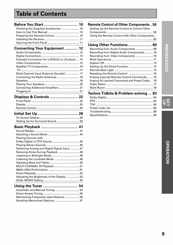
Digital Connections
In order to use Dolby Digital/DTS soundtracks which are at the heart of home theater you need to makedigital audio connections. You can do this by either a coaxial or an optical connection (you don’t need to doboth). The quality of these two types of connections is the same but since some digital components onlyhave one type of digital terminal, it is a matter of matching like with like (for example, the coaxial out fromthe component to coaxial in on the receiver). The VSX-37TX/36TX has two coaxial and three optical inputsfor a total of five digital inputs. For the VSX-37TX, A DVD/LD player or LD player should be connected to adigital jack and the special 2 RF jack (if the LD has one) as well as a pair of analog jacks (see the nextpage). If possible hook up your digital equipment in accordance with this receiver's default settings, see"Digital Input Assignment", below left, in order to do this. We also recommend hooking up your digitalcomponents to analog audio jacks in order to make recording from some digital sources which may becopy protected.
Connect your digital components as shown below.There are two optical digital out jacks (the MD recorder is connected to one in the diagram below). If youconnect this to the optical input on a digital recorder (currently these include MD, DAT and CD-R) you canmake direct digital recordings with this unit.
Before making or changing the connections, switch off the power and disconnect the power cord fromthe AC outlet.
*The arrows indicate the direction of the audio signal.
CDIN
SURR-OUND
SUBWOOFER
CENTER
FRONT
MULTI CH IN
SURR-OUND
R L
R L
R L
R L
R L (Single)
R
R
L
L
R
L
R L
FRONT
AUDIO
SUBWOOFER
PRE OUT
CENTER
COMPONENT VIDEODVD/LDIN
TV/SATIN
Y
PB
PR
MONITOROUT
MONITOROUT
MONITOROUT
PB
PR
Y
MULTI CH INSURROUND
BACK
SURROUNDBACK
PRE OUT
DVD /LDIN
S2 VIDEOVIDEOVIDEOAUDIO
IN
TV /SATIN
IN
OUT
IN
VCR1 /DVR
OUT
IN
OUT
IN
VCR2
OUT
IN
CONTROLMULTI-ROOM&
SOURCE
IN
OUT
MD /TAPE1/CD-R
PLAY
REC
TAPE2MONITOR
PLAY
REC
PCM/2/ DTS
DIGITALIN 5IN 4IN 32 RF IN
(AC-3)IN 2IN 1
INPHONO
FM UNBAL75‰
FMANTENNA
AM LOOPANTENNA
OUTOUT 21
MULTI-ROOM
&SOURCE
OUT
REMOTEIN
MD recorder
OUTPUT(PLAY)
INPUT(REC)
DIGITAL
TV tuner
DVD player
OUTPUT
DIGITAL
OUTPUT
DIGITALCD player
OUTPUT
DIGITAL
7 Coaxial cords/Optical cablesCommercially available digital audio coaxialcords (standard video cords can also beused) or optical cables (not supplied) areused to connect digital components to thisreceiver.
When you use optical digital input or outputterminals, pull off the caps and insert theplugs. Be sure to insert completely.
Coaxial cord
(or standard video cord)
Optical cable
Connecting Your Equipment
VSX-37TX
(for VSX-36TX DVD Player hookup see p.14)
(not a PCM-only output)

14
Example Connection for a DVD/LD or LD player
Make sure you connect your DVD/LD or LD players using both the 2 RF jack and either a coaxial or optical (youdon't need to do both of these) digital connections. If your player has an 2 RF output this will ensure you canuse all LDs (see p.15). We also recommend hooking up your digital components to analog audio jacks.Before making or changing the connections, switch off the power and disconnect the power cord from the ACoutlet.
*The arrows indicate the direction of the audio signal.
memo
CDIN
SURR-OUND
SUBWOOFER
CENTER
FRONT
MULTI CH IN
SURR-OUND
R L
R L
R L
R L
R L (Single)
R
R
L
L
R
L
R L
FRONT
AUDIO
SUBWOOFER
PRE OUT
CENTER
COMPONENT VIDEODVD/LDIN
TV/SATIN
Y
PB
PR
MONITOROUT
MONITOROUT 1
MONITOROUT
PB
PR
Y
MULTI CH INSURROUND
BACK
SURROUNDBACK
DVD /LDIN
S2 VIDEOVIDEOVIDEOAUDIO
IN
TV /SATIN
IN
OUT
IN
VCR1 /DVR
OUT
IN
OUT
IN
VCR2
OUT
IN
CONTROLMULTI-ROOM&
IN
OUT
MD /TAPE1/CD-R
PLAY
REC
TAPE2MONITOR
PLAY
REC
PCM/2/ DTS
DIGITALIN 5IN 4IN 32 RF IN
(AC-3)IN 2IN 1
INPHONO
FM UNBAL75‰
FMANTENNA
AM LOOPANTENNA
OUTOUT 21
MULTI-ROOM
&SOURCE
OUT
REMOTEIN
DVD/LD player
or LD player
1
2 3
DIGITAL OUT
(AC-3)(LD)RF OUT2
COMPO-NENT
VIDEOOUT
VIDEO
S-VIDEOPB
Y
STEREO
L
R
ANALOG
PR
Digital Input Assignment
Unlike analog connections, the jacks for digital connections are notdedicated to one type of component, they can be used freely. Thus youmust tell the receiver what digital component in which jack so yourcomponents will be in sync with the the names on the remote controlbuttons and the like. To avoid having to assign the digital inputs you canhook up your equipment in accordance with the receiver's default settings.
You will notice that Digital IN 1, for example, is a coaxial jack. If your DVD/LD player only has an optical out jack on it then you won't be able to hookup your components in accordance with the VSX-37TX/36TX defaultsetting. In this case you will need to assign the digital inputs. See Digital-InSelect on p.31 in order to do this.
Connecting Your Equipment
VSX-37TX model :
Be sure to make either a digital coaxial ordigital optical connection (pictured as DIGITALjack 1 or DIGITAL jack 3 in this diagram) aswell, but you DON'T need to make both.Also, be sure to assign the jacks to the propercomponent(s) with the Digital-In Selectprocedure (see p.31) if necessary. See theexplanation on the left for details.
VSX-36TX model :
When playing LD recorded in Dolby Digital
To connect a DVD/LD player or LD player with it's AC-3 RF output, a commercially available RF demodulator (RFD-1)is required. The RF demodulator changes the RF signal to a digital signal which is then processed by the VSX-36TXmodel through their digital input jacks. For more details, refer to the instruction manual supplied with the RFD-1.
memo
Make sure the RF demodulator digital inswitch is set correctly (optical or coaxialdepending on the connection).
(not a PCM-only output)
(not a PCM-only output)
CDIN
SURR-OUND
SUBWOOFER
CENTER
FRONT
MULTI CH IN
SURR-OUND
R L
R L
R L
R L
R L (Single)
R
R
L
L
R
L
R L
FRONT
AUDIO
SUBWOOFER
PRE OUT
CENTER
COMPONENT VIDEODVD/LDIN
TV/SATIN
Y
PB
PR
MONITOROUT
MONITOROUT 1
MONITOROUT
PB
PR
Y
MULTI CH INSURROUND
BACK
SURROUNDBACK
DVD /LDIN
S2 VIDEOVIDEOVIDEOAUDIO
IN
TV /SATIN
IN
OUT
IN
VCR1 /DVR
OUT
IN
OUT
IN
VCR2
OUT
IN
CONTROLMULTI-ROOM&
IN
OUT
MD /TAPE1/CD-R
PLAY
REC
TAPE2MONITOR
PLAY
REC
PCM/2/ DTS
DIGITALIN 5IN 4IN 3IN 2IN 1
INPHONO
FM UNBAL75‰
FMANTENNA
AM LOOPANTENNA
OUTOUT 21
MULTI-ROOM
&SOURCE
OUT
REMOTEIN
DVD/LD player
or LD player
RF demodulator RFD-1
1
2 3
DIGITAL OUT
(AC-3)(LD)RF OUT2
DIGITAL IN
PCM/ (OPT.)
PCM/
RF IN(AC-3)(LD)
DIGITAL OUT
PCM/ (OPT.)
PCM/
OPTICAL COAXIAL
DIGITAL IN
COMPO-NENT
VIDEOOUT
VIDEO
S-VIDEOPB
Y
PR
STEREO
L
R
ANALOG
7 The default settings
DIGITAL IN 1: DVD/LDDIGITAL IN 2: CDDIGITAL IN 3: MDDIGITAL IN 4: TV/SATDIGITAL IN 5: VCR1AC-3 RF: DVD/LD
15
PR
EPA
RA
TIO
N
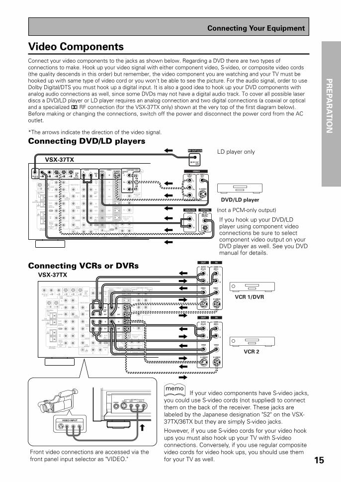
Video Components
Connect your video components to the jacks as shown below. Regarding a DVD there are two types ofconnections to make. Hook up your video signal with either component video, S-video, or composite video cords(the quality descends in this order) but remember, the video component you are watching and your TV must behooked up with same type of video cord or you won't be able to see the picture. For the audio signal, order to useDolby Digital/DTS you must hook up a digital input. It is also a good idea to hook up your DVD components withanalog audio connections as well, since some DVDs may not have a digital audio track. To cover all possible laserdiscs a DVD/LD player or LD player requires an analog connection and two digital connections (a coaxial or opticaland a specialized 2 RF connection (for the VSX-37TX only) shown at the very top of the first diagram below).Before making or changing the connections, switch off the power and disconnect the power cord from the ACoutlet.
*The arrows indicate the direction of the video signal.
CDIN
SURR-OUND
SUBWOOFER
CENTER
FRONT
MULTI CH IN
SURR-OUND
R L
R L
R L
R L
R L (Single)
R
R
L
L
R
L
R L
FRONT
AUDIO
SUBWOOFER
PRE OUT
CENTER
COMPONENT VIDEODVD/LDIN
TV/SATIN
Y
PB
PR
MONITOROUT
MONITOROUT
MONITOROUT
PB
PR
Y
MULTI CH INSURROUND
BACK
SURROUNDBACK
PRE OUT
DVD /LDIN
S2 VIDEOVIDEOVIDEOAUDIO
IN
TV /SATIN
IN
OUT
IN
VCR1 /DVR
OUT
IN
OUT
IN
VCR2
OUT
IN
CONTROLMULTI-ROOM&
SOURCE
IN
OUT
MD /TAPE1/CD-R
PLAY
REC
TAPE2MONITOR
PLAY
REC
PCM/2/ DTS/
DIGITALIN 5IN 4IN 32 RF IN
(AC-3)IN 2IN 1
INPHONO
FM UNBAL75‰
FMANTENNA
AM LOOPANTENNA
OUTOUT 21
MULTI-ROOM
&SOURCE
OUT
REMOTEIN
DVD/LD player
COMPO-NENT
VIDEOOUT
L
VIDEO
STEREO
L
R
DIGITALANALOGPCM/
2/ DTSDIGITAL
S-VIDEO
Y
PB
PR
RF OUT (LD)
2 RF OUT(LD)
CDIN
SURR-OUND
SUBWOOFER
CENTER
FRONT
MULTI CH IN
SURR-OUND
R L
R L
R L
R L
R L (Single)
R
R
L
L
R
L
R L
FRONT
AUDIO
PRE OUT
CENTER
COMPONENT VIDEODVD/LDIN
TV/SATIN
Y
PB
PR
MONITOROUT
MONITOROUT
MONITOROUT
PB
PR
Y
MULTI CH INSURROUND
BACK
SURROUNDBACK
PRE OUT
DVD /LDIN
S2 VIDEOVIDEOVIDEOAUDIO
IN
TV /SATIN
IN
OUT
IN
VCR1 /DVR
OUT
IN
OUT
IN
VCR2
OUT
IN
CONTROLMULTI-ROOM&
SOURCE
IN
OUT
MD /TAPE1/CD-R
PLAY
REC
TAPE2MONITOR
PLAY
REC
PCM/2/ DTS
DIGITALIN 5IN 4IN 32 RF IN
(AC-3)IN 2IN 1
INPHONO
FM UNBAL75‰
FMANTENNA
AM LOOPANTENNA
OUTOUT 21
MULTI-ROOM
&SOURCE
OUT
REMOTEIN
SUBWOOFER
PHONES S-VIDEO VIDEO L AUDIO R
VIDEO INPUT
LV R
VIDEO INPUT
VCR 1/DVR
VCR 2
VIDEO
S-VIDEO
VIDEO
S-VIDEO
AUDIO(PLAY)
L
R
AUDIO(REC)
L
R
S-VIDEO
VIDEOVIDEO
S-VIDEO
AUDIO(PLAY)
L
R
AUDIO(REC)
L
R
OUT IN
OUT IN
Connecting DVD/LD players
Connecting VCRs or DVRs
LD player only
Connecting Your Equipment
If you hook up your DVD/LDplayer using component videoconnections be sure to selectcomponent video output on yourDVD player as well. See you DVDmanual for details.
Front video connections are accessed via thefront panel input selector as "VIDEO."
If your video components have S-video jacks,you could use S-video cords (not supplied) to connectthem on the back of the receiver. These jacks arelabeled by the Japanese designation "S2" on the VSX-37TX/36TX but they are simply S-video jacks.
However, if you use S-video cords for your video hookups you must also hook up your TV with S-videoconnections. Conversely, if you use regular compositevideo cords for video hook ups, you should use themfor your TV as well.
memo
(not a PCM-only output)
VSX-37TX
VSX-37TX

16
CDIN
SURR-OUND
SUBWOOFER
CENTER
FRONT
MULTI CH IN
SURR-OUND
FRONT
LR
L
L
L
LR
R
R
R
L
R
SUBWOOFER
PRE OUT
CENTER
COMPONENT VIDEODVD/LDIN
TV/SATIN
Y
PB
PR
MONITOR OUT
PB
PR
Y
MULTI CH INSURROUND
BACK
DVD /LDIN
S2 VIDEOVIDEOVIDEOAUDIO
IN
TV /SATIN
IN
OUT
IN
VCR1 /DVR
OUT
IN
OUT
IN
VCR2
OUT
IN
MONITOROUTMD /
TAPE1/CD-R
PLAY
REC
TAPE2MONITOR
PLAY
REC
IN 5IN 4IN 32 RF IN(AC-3)
IN 2IN 1
INPHONO
FM UNBAL75‰
FMANTENNA
AM LOOPANTENNA
MULTI-ROOM
&SOURCE
OUT AUDIO
OUTOUT 21
MONITOROUT
CONTROLMULTI-ROOM&
SOURCE
IN
OUTREMOTE
IN R L (Single)
R L
SURROUNDBACK
PRE OUT
PCM/2/ DTS
DIGITAL
TV/Satellite tuner
COMPO-NENT
VIDEOOUT
VIDEO
STEREO
L
R
DIGITALANALOGDIGITAL
S-VIDEO
Y
PB
PR
Satellite TV Components
Connect your satellite TV components to the jacks as shown below. Hook up the video signal with eithercomponent video, S-video, or composite video cords (the quality descends in this order) but remember, thevideo component you are watching and your TV must be hooked up with same type of video cord or you won'tbe able to see the picture. For the audio signal, order to use digital soundtracks (sometimes broadcast overdigital satellite TV) you must hook up a digital input. Use either a coaxial or optical cables, it doesn't matterwhich (you don't need to use both). It's also a good idea to hook up your audio with analog cables (see below).This connection is called STEREO AUDIO OUT in the diagram.Before making or changing the connections, switch off the power and disconnect the power cord from the ACoutlet.
*The arrows indicate the direction of the TV signal.
7 Analog audio/video cordsUse audio/video cords (not supplied) toconnect the video components and a videocord to connect the monitor TV.
Connect red plugs to R (right), white plugs toL (left), and the yellow plugs to VIDEO.
Be sure to insert completely.
7 Digital audio coaxial cords/
Optical cablesCommercially available digital audio coaxialcords (standard video cords can also beused) or optical cables (not supplied) areused to connect digital components to thisreceiver.When you use optical digital input or outputterminals, pull off the caps and insert theplugs. Be sure to insert completely.
Digital audio coaxial
cord
(or standard video
cord)
Optical cable
LR
VIDEO
Connecting Your Equipment
VSX-37TX
17
PR
EPA
RA
TIO
N
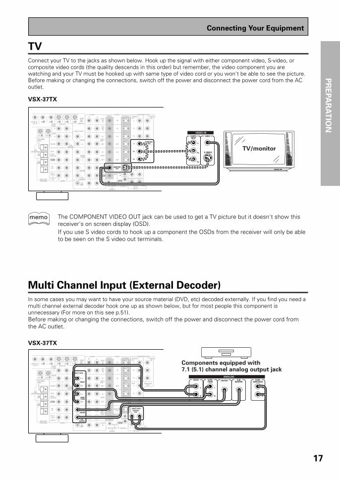
TV
Connect your TV to the jacks as shown below. Hook up the signal with either component video, S-video, orcomposite video cords (the quality descends in this order) but remember, the video component you arewatching and your TV must be hooked up with same type of video cord or you won't be able to see the picture.Before making or changing the connections, switch off the power and disconnect the power cord from the ACoutlet.
CDIN
SURR-OUND
SUBWOOFER
CENTER
FRONT
MULTI CH IN
SURR-OUND
FRONT
SUBWOOFER
PRE OUT
CENTER
COMPONENT VIDEODVD/LDIN
TV/SATIN
Y
PB
PR
MONITOR OUT
PB
PR
Y
MULTI CH INSURROUND
BACK
DVD /LDIN
S2 VIDEOVIDEOVIDEOAUDIO
IN
TV /SATIN
IN
OUT
IN
VCR1 /DVR
OUT
IN
OUT
IN
VCR2
OUT
IN
MONITOROUTMD /
TAPE1/CD-R
PLAY
REC
TAPE2MONITOR
PLAY
REC
IN 5IN 4IN 32 RF IN(AC-3)
IN 2IN 1
INPHONO
FM UNBAL75‰
FMANTENNA
AM LOOPANTENNA
MULTI-ROOM
&SOURCE
OUTAUDIO
OUTOUT 21
R
R L
L (Single)
MONITOROUT
SURROUNDBACK
PRE OUT
CONTROLMULTI-ROOM&
SOURCE
IN
OUTREMOTE
IN
R L
R L
R L
R
R
L
L
R
L
R L
PCM/2/ DTS
DIGITAL
TV/monitor
COMPO-NENT
VIDEO
VIDEO IN
S-VIDEO
Y
PB
PR
Multi Channel Input (External Decoder)
In some cases you may want to have your source material (DVD, etc) decoded externally. If you find you need amulti channel external decoder hook one up as shown below, but for most people this component isunnecessary (For more on this see p.51).Before making or changing the connections, switch off the power and disconnect the power cord fromthe AC outlet.
CDIN
SURR-OUND
SUBWOOFER
CENTER
FRONT
MULTI CH IN
SURR-OUND
R L
R
R
R
L L
R
L
L
R L
FRONT
SUBWOOFER
PRE OUT
CENTER
COMPONENT VIDEODVD/LDIN
TV/SATIN
Y
PB
PR
OUT MONITOROUT
PB
PR
Y
MULTI CH INSURROUND
BACK
DVD /LDIN
S2 VIDEOVIDEOVIDEOAUDIO
IN
TV /SATIN
IN
OUT
IN
VCR1 /DVR
OUT
IN
OUT
IN
VCR2
OUT
IN
MONITOROUTMD /
TAPE1/CD-R
PLAY
REC
TAPE2MONITOR
PLAY
REC
IN 5IN 4IN 32 RF IN(AC-3)
IN 2IN 1
INPHONO
FM UNBAL75‰
FMANTENNA
AM LOOPANTENNA
MULTI-ROOM
&SOURCE
AUDIO
OUTOUT 21
R
R L
L (Single)
MONITOROUT
SURROUNDBACK
PRE OUT
CONTROLMULTI-ROOM&
SOURCE
IN
OUTREMOTE
IN
PCM/2/ DTS
DIGITALComponents equipped with7.1 (5.1) channel analog output jack
SUBWOOFER
SURR-OUND BACK
L
R
CENTERSURR-OUND
L
R
FRONT
L
R
ANALOG
Connecting Your Equipment
The COMPONENT VIDEO OUT jack can be used to get a TV picture but it doesn't show thisreceiver's on screen display (OSD).If you use S video cords to hook up a component the OSDs from the receiver will only be ableto be seen on the S video out terminals.
memo
VSX-37TX
VSX-37TX
18
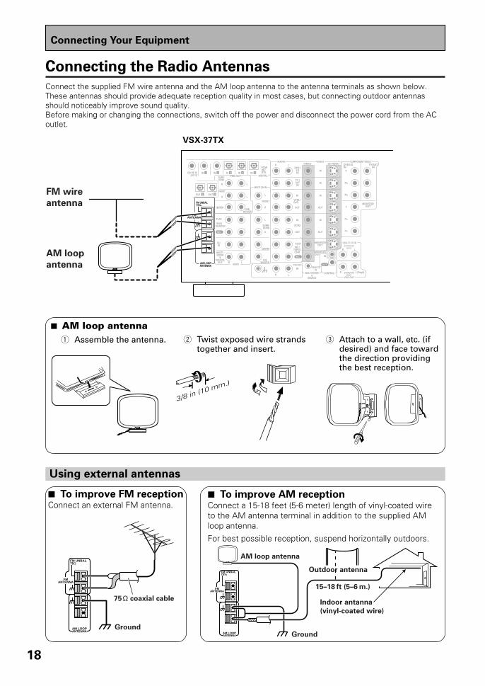
Connecting the Radio Antennas
Connect the supplied FM wire antenna and the AM loop antenna to the antenna terminals as shown below.These antennas should provide adequate reception quality in most cases, but connecting outdoor antennasshould noticeably improve sound quality.Before making or changing the connections, switch off the power and disconnect the power cord from the ACoutlet.
CDIN
SURR-OUND
SUBWOOFER
CENTER
FRONT
MULTI CH IN
SURR-OUND
R L
R L
R L
R L
R L (Single)
R
R
L
L
R
L
R L
FRONT
AUDIO
SUBWOOFER
PRE OUT
CENTER
COMPONENT VIDEODVD/LDIN
TV/SATIN
Y
PB
PR
MONITOROUT
MONITOROUT
MONITOROUT
PB
PR
Y
MULTI CH INSURROUND
BACK
SURROUNDBACK
PRE OUT
DVD /LDIN
S2 VIDEOVIDEOVIDEOAUDIO
IN
TV /SATIN
IN
OUT
IN
VCR1 /DVR
OUT
IN
OUT
IN
VCR2
OUT
IN
CONTROLMULTI-ROOM&
SOURCE
IN
OUT
MD /TAPE1/CD-R
PLAY
REC
TAPE2MONITOR
PLAY
REC
PCM/2/ DTS
DIGITALIN 5IN 4IN 32 RF IN
(AC-3)IN 2IN 1
INPHONO
FM UNBAL75‰
FMANTENNA
AM LOOPANTENNA
OUTOUT 21
MULTI-ROOM
&SOURCE
OUT
REMOTEIN
FM wire
antenna
AM loop
antenna
Using external antennas
FM UNBAL75‰
FMANTENNA
AM LOOPANTENNA
Outdoor antenna
Ground
15–18 ft (5–6 m.)
Indoor antanna
(vinyl-coated wire)
AM loop antennaFM UNBAL75Ω
FMANTENNA
AM LOOPANTENNA
Ground
75Ω coaxial cable
Connecting Your Equipment
3/8 in (10 mm.)
7 AM loop antenna1 Assemble the antenna. 2 Twist exposed wire strands
together and insert.3 Attach to a wall, etc. (if
desired) and face towardthe direction providingthe best reception.
7 To improve AM receptionConnect a 15-18 feet (5-6 meter) length of vinyl-coated wireto the AM antenna terminal in addition to the supplied AMloop antenna.For best possible reception, suspend horizontally outdoors.
7 To improve FM receptionConnect an external FM antenna.
VSX-37TX

19
PR
EPA
RA
TIO
N
Speakers
A full complement of eight speakers is shown here but, naturally, everyone's home set up will vary. Simply connectthe speakers you have in the manner described below. The receiver will work with just two stereo speakers (called"front" speakers in the diagram) but the receiver is designed to be used with at least three speakers.
One of the latest features of home theater is the use of SURROUND BACK speakers. These speakers add evengreater realism in movie sound effects and new discs with soundtracks in Dolby Digital or DTS incorporates thesechannels. In order to be able to use these channels you must hook your SURROUND BACK speakers up to anexternal amplifier and then connect that to the VSX-37TX/36TX, as shown in the diagram below. If you only have oneSURROUND BACK speaker hook it up to the SURROUND BACK L (SINGLE) terminal on the back of the receiver.
In general, make sure you connect the speaker on the right to the right terminal and the speaker on the left to theleft terminal. Also make sure the positive and negative (+/–) terminals on the receiver match those on the speakers.Before making or changing the connections, switch off the power and disconnect the power cord from the ACoutlet.
The receiver has two speaker systems, A & B. A is the main system supporting the full complement of surroundsound speakers. If you switch on both A & B speaker systems, only front speakers and the subwoofer will beaudible. No sound will come from the center or surround speakers but multi channel sources will be down-mixedto the active speakers so no sound will be lost. Similarly, if you choose just the B system you‘ll only hear thefront speakers connected to the B system and multi channel sources will be down-mixed to these two speakers.For the VSX-37TX you can use speakers with a nominal impedance rated 6Ω-16Ω, for the VSX-36TXsee the following page.
CDIN
SURR-OUND
SUBWOOFER
CENTER
FRONT
MULTI CH IN
SURR-OUND
R
R
L
LR L
R L
R L
R L
R L
FRONT
SUBWOOFER
PRE OUT
CENTER
DVD /LDIN
S2 VIDEOVIDEOVIDEOAUDIO
IN
TV /SATIN
IN
OUT
IN
VCR1 /DVR
OUT
IN
OUT
IN
VCR2
OUT
IN
MONITOROUTMD /
TAPE1/CD-R
PLAY
REC
TAPE2MONITOR
PLAY
REC
PCM/2/DTSDIGITAL
IN 5IN 4IN 32 RF IN(AC-3)
IN 2IN 1
INPHONO
FM UNBAL75‰
FMANTENNA
AM LOOPANTENNA
MULTI-ROOM
&SOURCE
OUT AUDIO
OUTOUT 21
SPEAKERS
COMPONENT VIDEODVD/LD
INTV/SAT
INY
MONITOROUTY
MULTI CH INSURROUND
BACK
A FRONT CENTER SURROUND FRONTB
SWITCHEDTOTAL 100W(0.8A)MAX
UNSWITCHED100W(0.8A)MAX
AC120V 60Hz
AC OUTLETS
Surroundspeaker(Right)
Surround backspeaker (Right)
Surround backspeaker (Left)
INPUT
Powered subwoofer
Surroundspeaker
(Left)
Front speaker (A)
(Left)
Frontspeaker (A)
(Right)
TV/monitor
Center speaker
R L (Single)
MONITOROUT
SURROUNDBACK
PRE OUT
CONTROLMULTI-ROOM&
SOURCE
IN
OUTREMOTE
IN
Additional Amplifier (See p.21)
memo
Connecting Your Equipment
7 Speaker terminals
1 Twist exposed wirestrands together.
2 Loosen speaker terminaland insert exposed wire.
3 Tightenterminal.
3/8 in. (10 mm)
The speaker terminalsalso accept single bananaplugs.(Refer to speaker manualfor details.)
VSX-37TX

20
Connecting Your Equipment
Placing Your Speakers
Proper speaker placement is essential to realize the best sound from your system. The diagram and tips givenhere are just a rough guide; be sure to read the instructions that come with your speakers.
• Install the left and right front speakers at equal distances from the TV.• When installing speakers near the TV, we recommend using magnetically shielded speakers to prevent
possible interference such as distortion in the color of the TV screen. If you do not have magneticallyshielded speakers and notice discoloration of the TV screen, place the speakers farther away from the TV.
• Install the center speaker above or below the TV so that the sound of the center channel is localized atthe TV screen.
CAUTION:When installing the center speaker on top of the TV, be sure to secure it with tape or some other suitable means. Otherwise, the speakermay fall from the TV due to external shocks such as earthquakes, and it may lead to endangering those nearby or damaging the speaker.
• If possible, install the surround speakers slightly above ear level.• It may be difficult to obtain a cohesive surround effect if the surround speakers are installed farther
away from the listening position than the front and center speakers.
Speaker placement
If you have a multiple speaker arrangement the placement of the speakers is extremely important. To achieve the bestpossible surround sound, install your speakers as shown below. Make sure all speakers are installed securely to preventaccidents and improve sound quality. Be sure to consult your speaker manuals for the best placement of the speakers. Somespeakers are designed to be floor-standing but others benefit greatly from speakers stands which raise them off the floor.
memo
Surround Left
Surround Back Left
Surround Right
Surround BackRight
Listening Position
FrontLeft
FrontRightCenter
Sub Woofer
Speaker impedance
You can change the speaker impedance for 36TX but we recommend using speakers with an impedance of 8Ω-16Ω (the default setting). If you are using 6Ω- less than 8Ω impedance speakers, you need to change theimpedance setting. It is not necessary to switch the speaker impedance when using the VSX-37TX. Use anyspeaker rated between 6Ω-16Ω.
First turn the receiver off, then press the STANDBY/ON
button while holding down the SPEAKERS button.
Choose the impedance setting by pressing the SPEAKERS buttonagain. You can choose the 8Ω-16Ω setting or the 6Ω-8Ω setting.
To check which impedancesetting to hold down theSPEAKERS button for 2-3seconds. You'll get a display likethese telling you the speakerimpedance setting.
(This display indicates a 6Ω-less than 8Ω impedancesetting.)
(This display indicates an 8Ω-16Ω impedance setting.)
memo
STANDBY/ON DSPMODE
THX CINEMA ADVANCED STANDARD
STANDBY
AUDIO/VIDEO MULTI-CHANNEL RECEIVER
STEREO/DIRECT
/DTS
N∫m¿≤≥ım
PHONES S-VIDEO VIDEO
MULTI CH INPUT
SIGNALSELECT
FLDIMMER
TAPE 2MONITOR
TONECHANNEL
SELECT LOUDNESSDIGITAL
NR CLASS BAND
TUNER CONTROLMEMORYMPX
VIDEOSELCTSPEAKERS
- TUN
- STAT- TREBLE +- BASS +
L AUDIO RVIDEO INPUT
VIDEO VCR 1/DVR VCR 2 DVD/LD TV/SATMD/TAPE1/
CD-R TUNERCD PHONO
SPEAKERS
STANDBY/ON
dB
SIGNALSELECTANALOG SP A
VOLUME
dB
SIGNALSELECTANALOG SP A
VOLUME
21
PR
EPA
RA
TIO
N
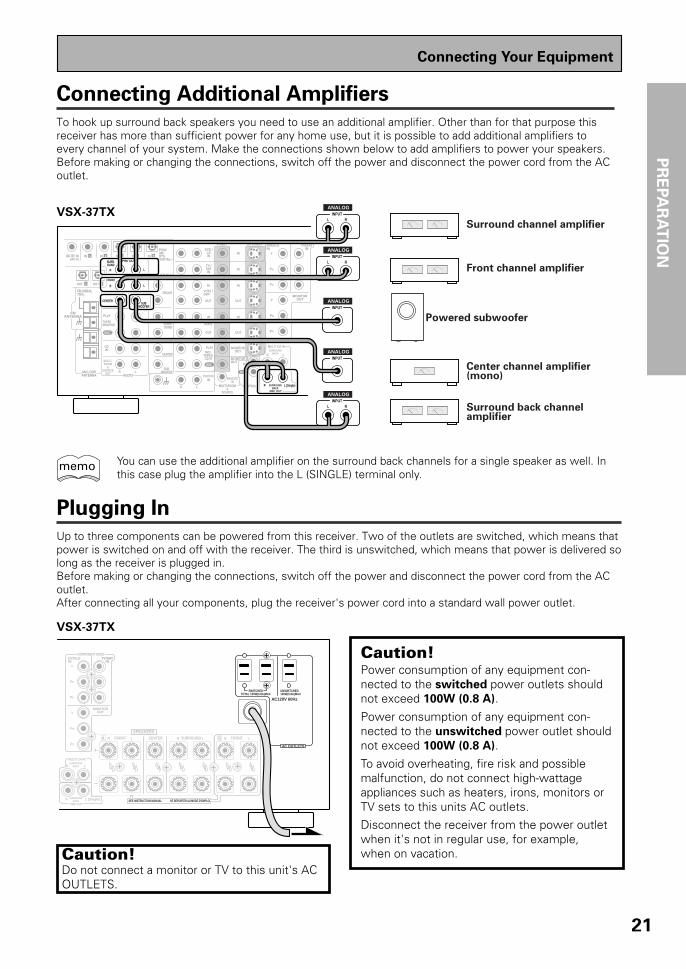
Connecting Additional Amplifiers
To hook up surround back speakers you need to use an additional amplifier. Other than for that purpose thisreceiver has more than sufficient power for any home use, but it is possible to add additional amplifiers toevery channel of your system. Make the connections shown below to add amplifiers to power your speakers.Before making or changing the connections, switch off the power and disconnect the power cord from the ACoutlet.
CDIN
SURR-OUND
SUBWOOFER
CENTER
FRONT
MULTI CH IN
SURR-OUND
FRONT
R L
R L
SUBWOOFER
PRE OUT
CENTER
COMPONENT VIDEODVD/LDIN
TV/SATIN
Y
PB
PR
MONITOROUT
PB
PR
Y
MULTI CH INSURROUND
BACK
SURROUNDBACK
PRE OUT
DVD /LDIN
S2 VIDEOVIDEOVIDEOAUDIO
IN
TV /SATIN
IN
OUT
IN
VCR1 /DVR
OUT
IN
OUT
IN
VCR2
OUT
IN
MONITOROUT
OUT
MD /TAPE1/CD-R
PLAY
REC
TAPE2MONITOR
PLAY
REC
PCM/2/DTSDIGITAL
IN 5IN 4IN 32 RF IN(AC-3)
IN 2IN 1
INPHONO
FM UNBAL75‰
FMANTENNA
AM LOOPANTENNA
MULTI-ROOM
&SOURCE
OUT AUDIO
OUTOUT 21
R L (Single)
MONITOROUT
CONTROLMULTI-ROOM&
SOURCE
IN
R L
R L
R L
REMOTEIN
Surround channel amplifier
Front channel amplifier
Center channel amplifier(mono)
Surround back channel amplifier
Powered subwoofer
INPUTL R
ANALOG
INPUTL R
ANALOG
INPUTL R
ANALOG
INPUTANALOG
INPUTANALOG
Plugging In
Up to three components can be powered from this receiver. Two of the outlets are switched, which means thatpower is switched on and off with the receiver. The third is unswitched, which means that power is delivered solong as the receiver is plugged in.Before making or changing the connections, switch off the power and disconnect the power cord from the ACoutlet.After connecting all your components, plug the receiver's power cord into a standard wall power outlet.
Caution!Power consumption of any equipment con-nected to the switched power outlets shouldnot exceed 100W (0.8 A).
Power consumption of any equipment con-nected to the unswitched power outlet shouldnot exceed 100W (0.8 A).
To avoid overheating, fire risk and possiblemalfunction, do not connect high-wattageappliances such as heaters, irons, monitors orTV sets to this units AC outlets.Disconnect the receiver from the power outletwhen it's not in regular use, for example,when on vacation.
SWITCHEDTOTAL 100W(0.8A)MAX
UNSWITCHED100W(0.8A)MAX
AC120V 60Hz
RA L R L R LFRONT CENTER SURROUND FRONTBSPEAKERS
SEE INSTRUCTION MANUAL SE REPORTER AU MODE D’EMPLOI
COMPONENT VIDEODVD/LDIN
TV/SATIN
MONITOROUT
Y
PB
PR
PB
PR
Y
R L
L (Single)R
MULTI CH INSURROUND
BACK
SURROUNDBACK
PRE OUT
AC OUTLETS
Connecting Your Equipment
You can use the additional amplifier on the surround back channels for a single speaker as well. Inthis case plug the amplifier into the L (SINGLE) terminal only.
memo
VSX-37TX
VSX-37TX
Caution!Do not connect a monitor or TV to this unit's ACOUTLETS.

22
Front Panel
All the controls on the front panel are explained and/or referenced here. To open the front panel pushgently on the lower third of the panel.
1 STANDBY/ON buttonPress to switch the receiver ON or intoSTANDBY mode.
STANDBY indicatorLights when the receiver is in STANDBY mode.(Please note that this receiver consumes asmall amount of power [1.0 W] in the standbymode.)
2 DSP MODE button (See p.43 & 44)Press repeatedly to select a DSP sound mode.(HALL 1, HALL 2, JAZZ, DANCE, THEATER 1,or THEATER 2, 5/7 CH STEREO). Use thesemodes to produce surround sound fromstandard (two channel) stereo sources andcreate different listening environments.
STEREO/DIRECT button (See p.43 & 52)Switches the receiver into STEREO mode if itwas in a different sound mode (like ADVANCEDTHEATER) or toggles between DIRECT andSTEREO mode. For more on STEREO modesee p.52DIRECT playback bypasses the tone controls,DIGITAL NR, LOUDNESS, MIDNIGHT andchannel level for the most accurate reproduc-tion of a program source.
STANDBY/ON DSPMODE
MULTI-ROOM&SOURCE
INPUTSELECTOR
MASTERVOLUME
MIN MAX
THX CINEMA ADVANCED STANDARD CONTROL
STANDBY
AUDIO/VIDEO MULTI-CHANNEL RECEIVER
STEREO/DIRECT
/DTS
N∫m¿≤≥ım
PHONES S-VIDEO VIDEO
MULTI CH INPUT
SIGNALSELECT
FLDIMMER
TAPE 2MONITOR
TONECHANNEL
SELECT LOUDNESSDIGITAL
NR CLASS BAND
TUNER CONTROLMEMORYMPX
VIDEOSELECTSPEAKERS
- TUNING +
- STATION +- TREBLE +- BASS +
L AUDIO RVIDEO INPUT
VIDEO VCR 1/DVR VCR 2 DVD/LD TV/SATMD/TAPE1/
CD-R TUNERCD PHONO
1 2 53 6 7 8 9
10 11 12 13 14 15
17
16
4
/ DTS buttons (See p.41-45, 83, 84)THX CINEMA – Cycles through the THXCINEMA, THX SURROUND EX or THX AUTOsound modes. Use when listening THX-certified sources if you have THX-certifiedspeaker setup or want to re-create a THX-stylesound environment. It is also appropriate forDolby Digital, Dolby Pro Logic or DTS sources.Those with surround back speakers can use allthree THX modes, those without can only usethe THX CINEMA mode.
ADVANCED – Use to select one of the fourAdvanced Theater modes. Use to create certaintypes of sound environments when listening toDolby Digital, Dolby Pro Logic or DTS sources.
STANDARD – Use for pure decoding of multichannel sources, especially Dolby Digital, DolbyPro Logic or DTS sources. Each press togglesbetween STANDARD and STANDARD 7.1mode (for use with SURROUND BACK speak-ers) and STANDARD auto (the receiver choosesthe appropriate STANDARD mode). Those withsurround back speakers can use all threeSTANDARD modes, those without can only usethe STANDARD mode.
VSX-37TX
Displays & Controls
23
PR
EPA
RA
TIO
N
Displays & Controls
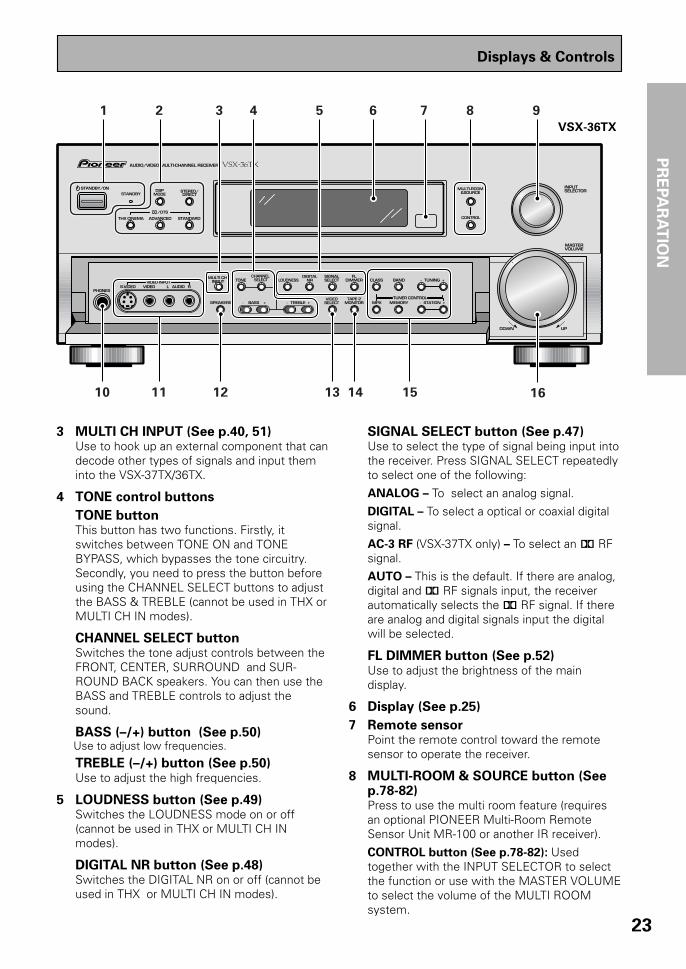
3 MULTI CH INPUT (See p.40, 51)Use to hook up an external component that candecode other types of signals and input theminto the VSX-37TX/36TX.
4 TONE control buttons
TONE buttonThis button has two functions. Firstly, itswitches between TONE ON and TONEBYPASS, which bypasses the tone circuitry.Secondly, you need to press the button beforeusing the CHANNEL SELECT buttons to adjustthe BASS & TREBLE (cannot be used in THX orMULTI CH IN modes).
CHANNEL SELECT buttonSwitches the tone adjust controls between theFRONT, CENTER, SURROUND and SUR-ROUND BACK speakers. You can then use theBASS and TREBLE controls to adjust thesound.
BASS (–/+) button (See p.50)Use to adjust low frequencies.
TREBLE (–/+) button (See p.50)Use to adjust the high frequencies.
5 LOUDNESS button (See p.49)Switches the LOUDNESS mode on or off(cannot be used in THX or MULTI CH INmodes).
DIGITAL NR button (See p.48)Switches the DIGITAL NR on or off (cannot beused in THX or MULTI CH IN modes).
SIGNAL SELECT button (See p.47)Use to select the type of signal being input intothe receiver. Press SIGNAL SELECT repeatedlyto select one of the following:
ANALOG – To select an analog signal.
DIGITAL – To select a optical or coaxial digitalsignal.
AC-3 RF (VSX-37TX only) – To select an 2 RFsignal.AUTO – This is the default. If there are analog,digital and 2 RF signals input, the receiverautomatically selects the 2 RF signal. If thereare analog and digital signals input the digitalwill be selected.
FL DIMMER button (See p.52)Use to adjust the brightness of the maindisplay.
6 Display (See p.25)
7 Remote sensorPoint the remote control toward the remotesensor to operate the receiver.
8 MULTI-ROOM & SOURCE button (Seep.78-82)Press to use the multi room feature (requiresan optional PIONEER Multi-Room RemoteSensor Unit MR-100 or another IR receiver).
CONTROL button (See p.78-82): Usedtogether with the INPUT SELECTOR to selectthe function or use with the MASTER VOLUMEto select the volume of the MULTI ROOMsystem.
STANDBY/ON DSPMODE
MULTI-ROOM&SOURCE
INPUTSELECTOR
MASTERVOLUME
THX CINEMA ADVANCED STANDARD CONTROL
STANDBY
AUDIO/VIDEO MULTI-CHANNEL RECEIVER
STEREO/DIRECT
/DTS
N∫m¿≤>ım
DOWN UP
PHONES S-VIDEO VIDEO
MULTI CH INPUT
SIGNALSELECT
FLDIMMER
TAPE 2MONITOR
TONECHANNEL
SELECT LOUDNESSDIGITAL
NR CLASS BAND
TUNER CONTROLMEMORYMPX
VIDEOSELECTSPEAKERS
- TUNING +
- STATION +- TREBLE +- BASS +
L AUDIO RVIDEO INPUT
1 2 53 6 7 8 9
10 11 12 13 14 15 16
4
VSX-36TX

24
9 INPUT SELECTOR dialTurn to select a source component. (You canalso use to select a function in the MULTI-ROOM & SOURCE mode). The source indica-tors show the current component:
DVD/LD – DVD player or Laser Disc player.TV/SAT– TV or satellite tuner.
CD – Compact Disc player.
MD/TAPE1/CD-R – Tape deck, Mini Discrecorder or CD recorder connected to MD/TAPE 1/CD-R inputs/outputs.
TUNER – The built-in tuner.PHONO – Turntable.
VIDEO – Video camera (etc.) connected to theVIDEO INPUT on the front panel.
VCR1/DVR – Video cassette recorder connect-ed to VCR1/DVR inputs.
VCR 2 – Video cassette recorder or othercomponent connected to VCR 2 inputs.
10 PHONES jackConnect headphones for private listening (nosound will be heard through the speakers).
11 VIDEO INPUT jacks (See p.15)S-VIDEO: Video input for connecting a videocamera (etc.), that has an S-Video out.
VIDEO/AUDIO (L/R): Video input for connect-ing a video camera, etc. that has standardvideo/audio outputs.
12 SPEAKERS (A/B) buttonUse to select the speaker system. A is theprimary setting. It plays all speakers hooked upto the A system. A & B setting only plays thefront speakers of both the A & B systems andthe subwoofer. Multi channel sources will bedown-mixed to these speakers so no sound willbe lost. B setting only plays the front speakersconnected to the B system and multi channelsources will be down-mixed to these twospeakers. The button cycles through thespeaker systems as follows: A]B]A&B]off.
13 VIDEO SELECT buttonSwitches the receiver between the varioustypes of video input.
14 TAPE 2 MONITOR buttonSelects the tape deck (MD recorder, etc.)connected to the TAPE 2 MONITOR inputs/outputs. Allows monitoring of a recording asit's being made.
Displays & Controls
15 TUNER CONTROL buttons (See p.54-57)CLASS – Press repeatedly to switch the presetstation classes.
BAND – Press to select the AM or FM band.TUNING –/+ – Use to manually tune to radiostations.
MPX – Press to switch between auto stereoand MONO reception of FM broadcasts. Whenthe broadcast signal is weak, selecting MONOwill improve the sound quality.
MEMORY – Press to start the memorization ofa preset station.
STATION –/+ – Use to choose programmedradio stations.
16 MASTER VOLUMEAdjusts the overall receiver volume.
17 Source indicators (VSX-37TX only)Shows the source currently selected.

25
PR
EPA
RA
TIO
N
Displays & Controls
Display
All the display information is explained and/or referenced here.
1 SIGNAL SELECT indicatorsLight to indicate the input signal you selected.ANALOG : Lights when analog signals areassigned.DIGITAL: Lights when digital audio signals areselected.AC-3 RF(VSX-37TX only): Lights when AC-3 RFsignals are assigned.AUTO: Lights when the receiver is set to selectthe input signal automatically.
2 Program Format indicatorsAC-3: Lights when a source with Dolby Digitalsignals is played.DTS: Lights when a source with DTS audiosignals is played.For Dolby Digital or DTS sources: Theseindicators change according to which channels areactive in the source. When all three LS (leftsurround), S (surround) and RS (right surround)light at the same time it means a source with aSurround EX or DTS ES flag is being used.L – Left front channel.C – Center channel.R – Right front channel.LS – Left surround channel.S – Surround channel (mono).RS – Right surround channel.LFE – Low Frequency Effects channel.
3 Analog level indicatorsOVER – When the source signal is analog, thislights if the signal is in danger of distorting. PressINPUT ATT on the remote control to lower thesignal level.ATT – Lights when INPUT ATT is used to reducethe level of the analog source signal.
4 Speaker indicatorsLight to indicate the current speaker system, Aand/or B.
5 LOUDNESS indicator (See p.49)Lights when the LOUDNESS mode is on.
6 H.P (headphones)Lights when headphones are connected to thePHONES jack (speakers systems A and B bothturn off automatically).
DIGITALdB
PRO LOGICSTEREODSPMIDNIGHTLOUDNESSATTSIGNAL
SELECT OVER H.P
AC-3DTS
ANALOG SP AB
L C R LFE
LS S RS
DIGITALAC-3RFAUTO TAPE 2
VOLUME
MONO STEREOTUNED AMFM
21 3 4 5 6 7 8 9 10 11 12 13
1415
7 MIDNIGHT indicator (See p.49)Lights when the MIDNIGHT LISTENING modeis on.
8 DSP indicator (See p.41-45, 47)Light when a DSP or Advanced Theater modeis selected.
9 STEREO indicatorLights when a STEREO mode is selected.
10 Radio Frequency/Function indicatorDisplays the function or the frequency of thecurrent radio station.
11 2/dts mode indicators2 DIGITAL : When the 2 /dts mode on thereceiver is on, this indicator lights to indicateplayback of a Dolby Digital signal. However, 2PRO LOGIC lights during 2 channel playback ofDolby Digital.2 PRO LOGIC: When the 2 /dts mode on thereceiver is on, this indicator lights during 2 channelplayback.DTS : When the 2/dts mode on the receiver ison, this indicator lights to indicate playback of aDTS signal.THX: Lights when the HOME THX CINEMA modeis selected.
12 MASTER VOLUME indicationDisplays current volume level.
13 TAPE 2 indicatorLights when the TAPE 2 monitor is on.
14 Character displayShows current mode, status, etc.
15 Tuner indicatorsMONO: Lights when the tuner is set to receiveFM broadcasts and when selected MPX mode.STEREO: Lights when a FM stereo broadcast isreceived in the auto stereo mode.TUNED: Lights when a broadcast is received.AM/FM: Light to indicate the current band (FM orAM).

26
Remote Control
1 USE/SETUP slide switchUse to put the remote into receiver SETUP, orreceiver USE mode.
2 SOURCE buttonUse to turn on the power of your othercomponents after you have recalled or taughtthe signals to this remote control.
MULTI OPERATION buttonUse this button to start the MULTI OPERATIONmode. See page 71-72 for how to program anduse the MULTI OPERATION mode.
SYSTEM OFF buttonThis button turns off components in two ways.First, when pressed it will turn off all PIONEERcomponents. Secondly, any component thathas programmed into the SYSTEM OFFsettings will also be turned off (see p.73).For example : If you programmed power on foryour TV and VCR, pressing the SYSTEM OFFbutton will turn off these components even ifthey are not PIONEER products.
RECEIVER buttonPress to turn power of the receiver on or toSTANDBY (off).
3 MULTI CONTROL buttonsUse these to select a source and thecorresponding remote operation mode.For example, pressing TUNER selects the builtin tuner and sets the remote operation to thetuner functions.
4 Component Control buttonsUse to control specific components, like a CDplayer or DVD player, after you haveprogrammed the remote control to do theseoperations (see pages 58-61) and the remote isput in that operation mode.
5 Number buttonsThese buttons can perform a variety ofdifferent functions depending on the remoteoperation mode. They are most useful for CDand tuner operations.
6 TV CONTROL buttonsThe following buttons are used to control theTV only and can be used no matter whatfunction the remote control is set to.
TV button – Press to turn the power of theTV on/off.
TV FUNC button – Press TV FUNC to selectthe TV for remote control operation.
TV VOL +/- button – Use to adjust the TVvolume.
AV PRE-PROGRAMMED AND LEARNINGREMOTE CONTROL UNIT
S0URCE
DVD/LD TV/SAT VCR1 VCR2
CD
TV VOL
TV FUNC
MENU
ENTER
STEREO/DIRECTDSP
THXLIGHT
MUTE
TV
VOLUME
MD/TAPE1 TUNER TVCONT
RECEIVER
USE SETUP
MULTIOPERATION
CLASS MPX DIRECT ACCESS
CHANNEL
STATION
DTV ON/OFF DTV MENU
TUNING
TV CONTROL
FUNCTION
REMOTE SETUP
SYSTEM SETUP
INPUTATT
MIDNIGHT MULTI CHINPUT
STANDARD
DIGITALNR
EFFECT/CH SEL
SIGNALSELECT
BAND
SYSTEMOFF
1 2 3
4 5 6
7 8 9
0
Î
¶ 87 3
1 ¡ 4 ¢ +-
+-
+-
MULTI CONTROL
+ +
– –
+
–
ADVANCED
DISC
EXIT
+10
GUIDE
ENTER
/DTS
1
2
3
4
5
76
8
9
Displays & Controls

27
PR
EPA
RA
TIO
N
5(+)/∞(–)/2/3/ENTER buttonsUse to operate the on-screen menu on your TVscreen and enter commands when setting upsurround sound, speakers levels & settings,and other set up features see p.28-40. Specificuse of these buttons is described in conjunc-tion with the operations they perform. For moreinformation see each individual section.
DIGITAL NR buttonPress to switch Digital NR on or off. (See page48)
SIGNAL SELECT buttonPress SIGNAL SELECT repeatedly to select oneof the following:
ANALOG – Analog signal.
DIGITAL – Digital signal (DVD/LD, TV/SAT, CD,MD/TAPE 1/CD-R, VCR 1/DVR, VCR 2).AC-3 RF (VSX-37TX only) – 2 RF signal(DVD/LD, TV/SAT, VCR 1, VCR 2).
AUTO – This is the default. If there are bothanalog, digital, 2 RF input signals, thereceiver automatically selects the best possiblesignal.
9 MIDNIGHT button (See p.49)Switches the MIDNIGHT mode on or off.
MULTI CH INPUT button (See p.40, 51)Press to switch to MULTI CH IN mode.
DSP button (See p.41-45, 47)Press repeatedly to select a DSP sound mode.
STEREO/DIRECT button (See p.43 & 52)Switches the receiver into STEREO mode if itwas in a different sound mode (like ADVANCEDTHEATER) or toggles between DIRECT andSTEREO mode. For more on STEREO modesee p.52.
DIRECT playback bypasses the tone controlsand channel level for the most accuratereproduction of a program source.
LIGHT buttonPress to light the remote control buttons.
/DTS buttons (See p.41-45)Press these buttons to put the receiver in theselected sound mode. For more information onthe sound modes see p.83 & 84.
7 MASTER VOLUME buttonsUse to raise or lower the volume of thereceiver.
8 INPUT ATT button (when USE mode isselected)Use to lower the input level of an analog signalthat is too powerful, thus causing the sound todistort (the OVERLOAD indicator will light).
REMOTE SETUP button (when SETUPmode is selected)Use to customize the remote control functionsand the remote control itself. (See “Setting Upthe Remote Control to Control Other Compo-nents“ starting on p.58, “Multi Operation“starting on p.71)
MENU buttonUse to get the various menus for your TV orDTV.
MUTING buttonPress to mute or restore the volume.
EFFECT/CH SEL (when USE mode isselected) button (see memo on p.44)EFFECT – Use these buttons to increase ordecrease the amount of effect applied in a DSPor Advanced Theater mode. When the amountof effect is increased in a DSP/AdvancedTheater mode the characteristics of that modebecome stronger and more noticeable. Thescale ranges from 10-90 with 70 as the defaultsetting. First turn on the DSP/AdvancedTheater you want (by pressing the DSP/Advanced Theater button until you get themode) and then increase or decrease theamount of effect.CH SEL – You may want to adjust the channelswhen listening to some sound sources. Usethis button to select the channel you want toadjust.
SYSTEM SET UP button (when SETUPmode is selected)Use to set up the speaker and sound systems.For more information see “Setting up forSurround Sound“ starting on p.29.
FUNCTION buttonPress to select a source. The button will cyclethrough all the possible sources.
Displays & Controls

28
Switching video system between PAL and NTSC (if necessary)
This receiver is able to use two types of video systems for its OSD (on screen display) either PAL or NTSC. Ifyou don't match the system on the amplifier with your home system no OSD will appear on your TV. Thedefault setting is NTSC, which is the standard in North America. If you use this system you don't need tomake any settings here. People with multi-system TVs don’t need to worry about changing the setting either.If necessary, follow the instructions below to switch the type of video system.
1 Put the receiver in the STANDBY mode.
2 While holding down the LOUDNESS button
press the STANDBY/ON button.The video system type will change depending on the state thereceiver was previously in. The new type, either PAL or NTSC,will appear in the display. It will be shown for about sevenseconds and then the receiver returns to normal operatingmode.To change the video system type again repeat steps 1 and 2.
Make sure you press the LOUDNESS button, using othersbuttons may change this receiver’s settings.
When a PAL system is selected
dB
SIGNALSELECT
SP ADIGITAL
VOLUME
When a NTSC system is selected
When using the PAL setting the OSD does not get displayedin color.
On Screen Display
There are a number of possible ways to hook up the receiver to your video components, like a DVD player, andhook up to your receiver to your TV, but some of them will not allow you to use the on-screen display of thisunit. To avoid this, you simply need to keep the following rules:
1 Always use the same type of video cords to hook up your video components to the receiver as you use tohook up the receiver to your TV. For example, if you use composite video cords to hook up your DVD playerto the receiver, use composite video cords to hook up the receiver to your TV. If you use S video cords tohook up your DVD player and the receiver, use S video cords to hook up the receiver to your TV.
2 Always make sure your TV is set to the appropriate input channel (for example, video 1). Your TV may have anumber of input channels and if you do not select the proper one, you will not be able to use this receiver’son-screen display, or, in fact see any picture from this receiver at all. If you are unsure how to choose aninput channel for your TV, refer to the manual which came with your TV.
You might, for example, use both composite and S video cords to hook up your video components with thisreceiver and then use composite video cords to hook up this receiver to your TV. This arrangement would stillNOT let you see the on-screen displays from this receiver on your TV. The best idea is just to use one type ofvideo cords for all your video component and TV hook ups.
STANDBY/ON DSPMODE
THX CINEMA ADVANCED STANDARD
STANDBY
AUDIO/VIDEO MULTI-CHANNEL RECEIVER
STEREO/DIRECT
/DTS
N∫m¿≤≥ım
PHONES S-VIDEO VIDEO
MULTI CH INPUT TONE
CHANNEL SELECT LOUDNESS
DIGITALNR
SPEAKERS - TREBLE +- BASS +
L AUDIO RVIDEO INPUT
VIDEO VCR 1/DVR VCR 2 DVD/LD
STANDBY/ON
LOUDNESS
memo
Initial Set Up

29
SE
TU
P
Setting Up for Surround Sound
To ensure the best possible surround sound, be sure to complete the following setup operations. You only needto make these settings once (unless you change the placement of your current speaker system or add newspeakers, etc.).This receiver uses on-screen displays to make setting up your home cinema system easier. Switch on thereceiver and your TV, and make sure that the receiver is selected as your TV's video input.
1 Set the slide switch to SETUP.Also make sure your TV is on and set to the receiver.
• When you're done setting up the receiver, remember to
set the slide switch back to USE.
2 Press the SYSTEM SETUP button.
System Setup [Digital-In Select] [Speaker Setting] [Channel Delay] [Channel Level] [Crossover Network] [Bass Peak Level] [D-Range Control] [Multi Channel In] [Multi-Room]
This SYSTEM SETUP MENU appears on your TV screen.
dB
STEREOSIGNALSELECTANALOG SP A
AUTO
VOLUME
This display appears on the receiver.
• You can escape from this screen at any time by pressing theSYSTEM SETUP button again. None of the settings youmade will be entered in this case.
• If you don't enter any settings the receiver will revert back toits previous state after three minutes.
3 Press the 5 or ∞ arrow buttons to move the
hand to the mode you want. Then press the
ENTER button.In each mode, the current settings are displayed automatically.We suggest you adjust all these settings when you first hookup the receiver. That gets them out of the way and you won'tneed to return to this setting mode unless you change yourhome set up by adding new speakers (etc.). The sound set upmodes explained here are:
Digital In Select (See p.31)
In order to use your digital components you must match thenumbered digital input settings with the numbered digital jacksused by your digital components.
Speaker Setting (See p.32-33)
Use to specify the type and number of speakers youconnected.
Initial Set Up
AV PRE-PROGRAMMED AND LEARNINGREMOTE CONTROL UNIT
S0URCE
DVD/LD TV/SAT VCR1 VCR2
CD
TV VOL
TV FUNC
MENU
ENTER
STEREO/DIRECTDSP
THXLIGHT
MUTE
TV
VOLUME
MD/TAPE1 TUNER TVCONT
RECEIVER
USE SETUP
MULTIOPERATION
CLASS MPX DIRECT ACCESS
CHANNEL
STATION
TV CONTROL
FUNCTION
REMOTE SETUP
SYSTEM SETUP
INPUTATT
MIDNIGHT MULTI CHINPUT
STANDARD
DIGITALNR
EFFECT/CH SEL
BAND
SYSTEMOFF
1 2 3
4 5 6
7 8 9
0
Î
¶ 87 3
1 ¡ 4 ¢ +-
+-
+-
MULTI CONTROL
+ +
– –
+
–
1
32
ADVANCED
DISC
EXIT
+10
GUIDE
ENTER
/DTS
SIGNALSELECT
DTV ON/OFF DTV MENU
TUNING

30
Channel Delay (See p.34)
Set up all your speakers for the most realistic surround sound.Adding a slight delay to some speakers enhances soundseparation and is particularly important for achieving a surroundsound effect. You need to figure out the distance from yourlistening position to your speakers to add the proper delay.
Channel Level (See p.35-36)
Use to balance the volumes of your different speakers.
Crossover Network (See p.37)
This feature lets you select which bass frequencies will be sentto the subwoofer or front speakers.
Bass Peak Level (See p.38)
Dolby Digital and DTS audio sources include ultra-low basstones. Set the bass peak level as needed to prevent the ultra-low bass tones from distorting the sound from the speakers.
Dynamic Range Control (See p.39)
This feature makes possible excellent surround sound effectswhen listening to Dolby Digital sources at low volumes.
Multi Channel In Setting (See p.40)
This feature lets you hook up a multi channel external decoderthat may give you higher quality when decoding discs.Multi-Room (See p.78-82)You can set up this unit to power systems in different rooms.
4 Go on to the next page to continue set up.If you don't want to make any settings go can exit this setup.To exit the SYSTEM SETUP MENU and on-screen display pressSYSTEM SETUP button again.
After you complete one of the SYSTEM SETUP menus and returnto the basic SYSTEM SETUP screen the receiver automaticallymoves the cursor to the next SYSTEM SETUP menu. For example,if you've completed SPEAKER SETTINGS and returned to the basicSYSTEM SETUP screen, CHANNEL DELAY will be selectedautomatically. You can notice this on your TV screen.
memo
AV PRE-PROGRAMMED AND LEARNINGREMOTE CONTROL UNIT
S0URCE
DVD/LD TV/SAT VCR1 VCR2
CD
TV VOL
TV FUNC
MENU
ENTER
STEREO/DIRECTDSP
THXLIGHT
MUTE
TV
VOLUME
MD/TAPE1 TUNER TVCONT
RECEIVER
USE SETUP
MULTIOPERATION
CLASS MPX DIRECT ACCESS
CHANNEL
STATION
TV CONTROL
FUNCTION
REMOTE SETUP
SYSTEM SETUP
INPUTATT
MIDNIGHT MULTI CHINPUT
STANDARD
DIGITALNR
EFFECT/CH SEL
SIGNALSELECT
BAND
SYSTEMOFF
1 2 3
4 5 6
7 8 9
0
Î
¶ 87 3
1 ¡ 4 ¢ +-
+-
+-
MULTI CONTROL
+ +
– –
+
–
4
ADVANCED
DISC
EXIT
+10
GUIDE
ENTER
/DTS
DTV ON/OFF DTV MENU
TUNING
(to exitSYSTEMSETUP)
Initial Set Up

31
SE
TU
P
1 DIGITAL IN SELECT should be selected (if it
isn't use the 5¥∞ buttons to select it).See “Setting Up for Surround Sound“ on page 29 if you needmore information.
Press the ENTER button.
Digital-In Select
Digital-1Digital-2Digital-3Digital-4Digital-5AC-3 RF[EXIT] L
[DVD/LD][ CD ][ MD ][TV/SAT ][ VCR1 ][DVD/LD]
2 Choose a DIGITAL IN and assign it an input
function.Use 2 or 3 to choose the input function that matches thecomponent hooked up to that digital terminal.
The possible choices include: DVD/LD, TV/SAT, CD, MD/TAPE1/CD-R, VCR 1/DVR, VCR 2. You cannot assign digital inputs tothe TUNER, VIDEO, PHONO, and TAPE 2 MONITOR functions.If you assign a function (for example DVD/LD) that was previ-ously assigned to a different Digital In the second Digital In willautomatically revert to an OFF setting. This is because onefunction cannot be assigned twice.
3 Select EXIT and press ENTER button to
return to the SYSTEM SETUP MENU.If you want to change a setting before proceeding
simply use the arrow buttons to go back.
• For the Digital 1-5 setting you can choose between DVD/LD, CD, TV/SAT, MD/TAPE 1/CD-R, VCR 1/DVR and VCR 2functions.
• For the AC-3 RF setting you can choose between DVD/LD,TV/SAT, VCR 1/DVR and VCR 2 functions.
Remember, if you have a DVD/LD player or LD player youshould hook it up to the analog and digital jacks in addition tothe 2 RF connection described here.
Digital-In Select
In order to be able to use your digital equipment properly you need to assign digital inputs for each of the digitalcomponents you connected. Match the Digital 1-5 settings with the digital jacks 1-5 in accordance with what isconnected to each digital jack. Check the digital jack numbers on the back of the receiver to make certain whatcomponent is in which jack (if necessary, see page 13 for more on digital connections). The last setting, the AC-3 RF setting, is specifically for a DVD/LD player or LD player with an 2 RF output (VSX-37TX only). If youconnected one of these components match this button to the component. If continuing from the last page go tostep 1. If starting fresh, complete steps 1-3 in “Setting Up for Surround Sound“ (p.29) first.
AV PRE-PROGRAMMED AND LEARNINGREMOTE CONTROL UNIT
S0URCE
DVD/LD TV/SAT VCR1 VCR2
CD
TV VOL
TV FUNC
MENU
ENTER
STEREO/DIRECTDSP
THXLIGHT
MUTE
TV
VOLUME
MD/TAPE1 TUNER TVCONT
RECEIVER
USE SETUP
MULTIOPERATION
CLASS MPX DIRECT ACCESS
CHANNEL
STATION
TV CONTROL
FUNCTION
REMOTE SETUP
SYSTEM SETUP
INPUTATT
MIDNIGHT MULTI CHINPUT
STANDARD
DIGITALNR
EFFECT/CH SEL
SIGNALSELECT
BAND
SYSTEMOFF
1 2 3
4 5 6
7 8 9
0
Î
¶ 87 3
1 ¡ 4 ¢ +-
+-
+-
MULTI CONTROL
+ +
– –
+
–1-3
ADVANCED
DISC
EXIT
+10
GUIDE
ENTER
/DTS
DTV ON/OFF DTV MENU
TUNING
Initial Set Up

32
Speaker Setting
The following steps show you how to specify the type of speakers you connected. Use the 5¥∞ and 2¥3buttons to make a selection from the on-screen menus, and use the ENTER button to register the information. Ifcontinuing from the previous page go to step 1. If starting fresh, complete steps 1-3 on p.29 first.
1 Select SPEAKER SETTING (if continuing from
last set up, it will already be selected) with the
5¥∞ buttons then press the ENTER button.See “Setting Up for Surround Sound“ on page 29 if you areunsure how to do this.
2 Select a speaker setting mode with the 2¥3buttons then press the ∞ button.To specify each speaker individually select FREE.
If you connected a complete set of THX speakers select THXand skip the SURROUND BACK part of step 3.
3 Specify the type of speakers you connected.
See the explanations below for the meaning
of each size.1 Press 2 or 3 to move the hand to LARGE (or LARGE X2),
SMALL (or SMALL X2), or NO (you can't select NO for theFRONT speakers). For the subwoofer you can select YES,NO, or PLUS. See below for a detailed explanation of everyspeaker choice.
2 Press ∞.
3 Repeat 1 and 2 for each speaker.
Depending on your choices the sound will be routed
differently, as explained here.
FRONT (default setting is LARGE)
• Select SMALL to send bass frequencies to the subwoofer.
• Select LARGE if your speakers will reproduce bass frequen-cies effectively or if you did not connect a subwoofer.
(If you select SMALL for the front speakers the subwoofer willautomatically be set to YES. Also, the center, surround andsurround back speakers cannot be set to LARGE if the frontspeakers are set to SMALL. In this case, all bass frequencies aresent to the subwoofer.)
AV PRE-PROGRAMMED AND LEARNINGREMOTE CONTROL UNIT
S0URCE
DVD/LD TV/SAT VCR1 VCR2
CD
TV VOL
TV FUNC
MENU
ENTER
STEREO/DIRECTDSP
THXLIGHT
MUTE
TV
VOLUME
MD/TAPE1 TUNER TVCONT
RECEIVER
USE SETUP
MULTIOPERATION
CLASS MPX DIRECT ACCESS
CHANNEL
STATION
TV CONTROL
FUNCTION
REMOTE SETUP
SYSTEM SETUP
INPUTATT
ADVANCED
MIDNIGHT MULTI CHINPUT
STANDARD
DIGITALNR
EFFECT/CH SEL
SIGNALSELECT
BAND
SYSTEMOFF
1 2 3
4 5 6
7 8 9
0
Î
¶ 87 3
1 ¡ 4 ¢ +-
+-
+-
MULTI CONTROL
+ +
– –
+
–1-3
ADVANCED
DISC
EXIT
+10
GUIDE
ENTER
/DTS
DTV ON/OFF DTV MENU
TUNING
Initial Set Up
Speaker Setting
[FREE] [THX]
[LARGE][LARGE][LARGE][LARGEx2][ YES ]
Front LCenterSurroundSurrBack Subwoofer
[EXIT]
Speaker Setting
[FREE] [THX]
[LARGE][LARGE][LARGE][LARGEx2][ YES ]
Front LCenterSurroundSurrBack Subwoofer
[EXIT]

33
SE
TU
P
CENTER (default setting is LARGE)
• Select LARGE if your speaker will reproduce bass frequen-cies effectively.
• Select SMALL to send bass frequencies to the otherspeakers or the subwoofer.
• If you did not connect a center speaker, select NO. In thiscase, the center channel is output from the front speakers.
SURROUND (default setting is LARGE)
• Select LARGE if your speakers will reproduce bass frequen-cies effectively.
• Select SMALL to send bass frequencies to the otherspeakers or subwoofer.
• If you did not connect surround speakers select NO. In thiscase, the sound of the surround channels is output from thefront and center speakers.
• If the SURROUND speakers are set to SMALL, theSURROUND BACK speakers will automatically be set toSMALL.
SUBWOOFER (default setting is YES)
• Select YES if you connected a subwoofer.• If you did not connect a subwoofer select NO. In this case,
the bass frequencies are output from the front or surroundspeakers.
• Choose the PLUS setting if you want stronger reproductionof deep bass sounds.
• If you select PLUS the bass frequencies that would normallycome out the front and center speakers are all routed to thesubwoofer.
SURROUND BACK (default setting is LARGE X2)
NOTE: In order to use SURROUND BACK speakers you
need to hook them up through an external amplifier (see p.
19 & 21) for more on this.
• Select the number and size of SURROUND BACK speakersyou have. You can choose one speaker, two or none.
• If the FRONT speakers or the SURROUND speakers are set toSMALL, the SURROUND BACK speakers will automatically beset to SMALL.
• If you chose THX in step 2 then the SURROUND BACKspeakers can only be set to SMALL (or NO).
• Select LARGE if your speakers will reproduce bass frequen-cies effectively.
• Select SMALL to send bass frequencies to the otherspeakers or subwoofer.
• If you did not connect surround back speakers select NO.
4 Select EXIT with the 5¥∞ buttons and press
ENTER to return to the SYSTEM SETUP
MENU.Next, proceed to CHANNEL DELAY on the next page.
If you have a subwoofer and likelots of bass, it may seem logicalto select LARGE for your FRONTspeakers and leave thesubwoofer selected. This maynot, however, yield the best bassresults. Depending on the sizeand shape of your room you mayactually experience a decrease inthe amount of bass due to whatis called "low frequency cancella-tions." If you have a subwoofer,listen to the bass response withthe FRONT speakers set toLARGE and SMALL alternativelyand let your ears judge whichsounds best.
The safest option in this case isto route all the bass sounds tothe subwoofer by selectingSMALL for the FRONT speakers.
memo
AV PRE-PROGRAMMED AND LEARNINGREMOTE CONTROL UNIT
S0URCE
DVD/LD TV/SAT VCR1 VCR2
CD
TV VOL
TV FUNC
MENU
ENTER
STEREO/DIRECTDSP
THXLIGHT
MUTE
TV
VOLUME
MD/TAPE1 TUNER TVCONT
RECEIVER
USE SETUP
MULTIOPERATION
CLASS MPX DIRECT ACCESS
CHANNEL
STATION
TV CONTROL
FUNCTION
REMOTE SETUP
SYSTEM SETUP
INPUTATT
MIDNIGHT MULTI CHINPUT
STANDARD
DIGITALNR
EFFECT/CH SEL
SIGNALSELECT
BAND
SYSTEMOFF
1 2 3
4 5 6
7 8 9
0
Î
¶ 87 3
1 ¡ 4 ¢ +-
+-
+-
MULTI CONTROL
+ +
– –
+
–4
ADVANCED
DISC
EXIT
+10
GUIDE
ENTER
/DTS
DTV ON/OFF DTV MENU
TUNING
Initial Set Up

34
1 Select CHANNEL DELAY (if continuing from
last set up, it will already be selected).See “Setting Up for Surround Sound“ on page 29 if you areunsure how to do this.
Press the ENTER button.
[10.0ft][10.0ft][10.0ft][10.0ft] [10.0ft][10.0ft] [10.0ft][10.0ft]
Channel DelayFront LCenterFrontSurround Surr Back Surr BackSurroundSubwoofer[EXIT]
L
R
RRR
LL
• The default setting is 10 ft.
2 Use the 5¥∞ buttons to select a speaker.
Specify the distance from your listening
position to each speaker using the
commands below.1 Pres 2 or 3 to adjust the speaker distance in half foot
increments from 0.5 to 45 feet.The default setting is 10 feet.
2 Use the 5¥∞ buttons to move to the next set of speakers.3 Repeat for each speaker.
• Sound takes about 1 millisecond to travel 1 foot.
3 Select EXIT with the 5¥∞ buttons and press
ENTER button to return to the SYSTEM
SETUP MENU.Next, proceed to CHANNEL LEVEL on the next page.If you want to change a setting before proceeding simplyuse the arrow buttons to go back.
Channel Delay
Adding a slight delay to some speakers is necessary to achieve a surround sound effect. You need to figure outthe distance from your listening position to your speakers to add the proper delay. The following steps show youhow to set the delay time for each channel by specifying the distances from your listening position to eachspeaker. Once you specify the speaker distances, the receiver calculates the correct delay times automatically.If continuing from Speaker Setting go to step 1. If starting fresh, complete steps 1-3 in “Setting Up for SurroundSound“ (p.29) first.
AV PRE-PROGRAMMED AND LEARNINGREMOTE CONTROL UNIT
S0URCE
DVD/LD TV/SAT VCR1 VCR2
CD
TV VOL
TV FUNC
MENU
ENTER
STEREO/DIRECTDSP
THXLIGHT
MUTE
TV
VOLUME
MD/TAPE1 TUNER TVCONT
RECEIVER
USE SETUP
MULTIOPERATION
CLASS MPX DIRECT ACCESS
CHANNEL
STATION
TV CONTROL
FUNCTION
REMOTE SETUP
SYSTEM SETUP
INPUTATT
MIDNIGHT MULTI CHINPUT
STANDARD
DIGITALNR
EFFECT/CH SEL
SIGNALSELECT
BAND
SYSTEMOFF
1 2 3
4 5 6
7 8 9
0
Î
¶ 87 3
1 ¡ 4 ¢ +-
+-
+-
MULTI CONTROL
+ +
– –
+
–1-3
ADVANCED
DISC
EXIT
+10
GUIDE
ENTER
/DTS
DTV ON/OFF DTV MENU
TUNING
Initial Set Up
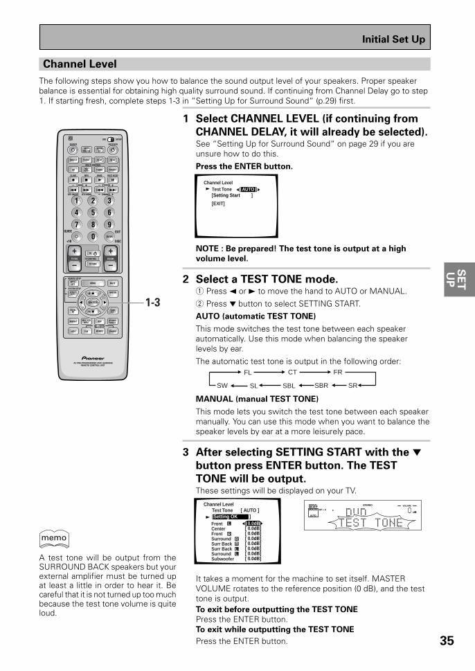
35
SE
TU
P
Channel Level
The following steps show you how to balance the sound output level of your speakers. Proper speakerbalance is essential for obtaining high quality surround sound. If continuing from Channel Delay go to step1. If starting fresh, complete steps 1-3 in “Setting Up for Surround Sound“ (p.29) first.
1 Select CHANNEL LEVEL (if continuing from
CHANNEL DELAY, it will already be selected).See “Setting Up for Surround Sound“ on page 29 if you areunsure how to do this.
Press the ENTER button.
NOTE : Be prepared! The test tone is output at a high
volume level.
2 Select a TEST TONE mode.1 Press 2 or 3 to move the hand to AUTO or MANUAL.
2 Press ∞ button to select SETTING START.AUTO (automatic TEST TONE)
This mode switches the test tone between each speakerautomatically. Use this mode when balancing the speakerlevels by ear.
The automatic test tone is output in the following order:
MANUAL (manual TEST TONE)
This mode lets you switch the test tone between each speakermanually. You can use this mode when you want to balance thespeaker levels by ear at a more leisurely pace.
3 After selecting SETTING START with the ∞button press ENTER button. The TEST
TONE will be output.These settings will be displayed on your TV.
It takes a moment for the machine to set itself. MASTERVOLUME rotates to the reference position (0 dB), and the testtone is output.To exit before outputting the TEST TONE
Press the ENTER button.To exit while outputting the TEST TONE
Press the ENTER button.
FL CT FR
SRSLSW SBL SBR
AV PRE-PROGRAMMED AND LEARNINGREMOTE CONTROL UNIT
S0URCE
DVD/LD TV/SAT VCR1 VCR2
CD
TV VOL
TV FUNC
MENU
ENTER
STEREO/DIRECTDSP
THXLIGHT
MUTE
TV
VOLUME
MD/TAPE1 TUNER TVCONT
RECEIVER
USE SETUP
MULTIOPERATION
CLASS MPX DIRECT ACCESS
CHANNEL
STATION
TV CONTROL
FUNCTION
REMOTE SETUP
SYSTEM SETUP
INPUTATT
MIDNIGHT MULTI CHINPUT
STANDARD
DIGITALNR
EFFECT/CH SEL
SIGNALSELECT
BAND
SYSTEMOFF
1 2 3
4 5 6
7 8 9
0
Î
¶ 87 3
1 ¡ 4 ¢ +-
+-
+-
MULTI CONTROL
+ +
– –
+
–1-3
ADVANCED
DISC
EXIT
+10
GUIDE
ENTER
/DTS
DTV ON/OFF DTV MENU
TUNING
dB
STEREOSIGNALSELECTANALOG SP A
AUTO
VOLUME
Initial Set Up
memo
A test tone will be output from theSURROUND BACK speakers but yourexternal amplifier must be turned upat least a little in order to hear it. Becareful that it is not turned up too muchbecause the test tone volume is quiteloud.
[ 0.0dB][ 0.0dB][ 0.0dB][ 0.0dB] [ 0.0dB][ 0.0dB] [ 0.0dB][ 0.0dB]
Channel Level
Front LCenterFrontSurround Surr BackSurr Back SurroundSubwoofer
L
RRRLL
Test Tone [ AUTO ][Setting OK ]
Channel LevelTest Tone [ AUTO ][Setting Start ]
[EXIT]

36
4 Adjust speaker levels so that you hear the
test tone at the same volume from each
speaker when seated in your main listening
position.Note: The volume of the subwoofer tends to sound lower thanit actually is, you may need to raise its level after testing thesound with actual soundtracks.
In AUTO mode
1 Press the 2 or 3 button to adjust the level of the speakeroutputting the TEST TONE.
In MANUAL mode
1 Press the 2 or 3 button to adjust the level of the firstspeaker.
2 Press the 5/∞ button to switch the TEST TONE to the nextspeaker.
3 Repeat 1 and 2 for each speaker.
If you are using a Sound Pressure Level (SPL) meter
Take the readings from your main listening position and adjustthe level of each speaker to 75 dB SPL (C-weighted/slowmode).
5 When you have adjusted each speaker level,
press ENTER button to return to the
previous screen.The MASTER VOLUME will return to its original position.
6 Select EXIT with the 5/∞ buttons and press
ENTER button to return to the SYSTEM
SETUP MENU.Next, proceed to CROSSOVER NETWORK on the next page.If you want to change a setting before proceeding simplyuse the arrow buttons to go back.
Note that it is also possible to setchannel levels temporarily. Then followthe same procedure as explained onthis page. This function is designed tobe used when you want to change thelevels temporarily to raise the level ofone channel. Using this method youcan set speaker levels in differentmodes, such as, STEREO, and eachDSP mode, independently. You shouldreturn the settings to their originalstate when done. Doing the set upprocedures on this page will erase anytemporary/independent level settingsthat have been made.
AV PRE-PROGRAMMED AND LEARNINGREMOTE CONTROL UNIT
S0URCE
DVD/LD TV/SAT VCR1 VCR2
CD
TV VOL
TV FUNC
MENU
ENTER
STEREO/DIRECTDSP
THXLIGHT
MUTE
TV
VOLUME
MD/TAPE1 TUNER TVCONT
RECEIVER
USE SETUP
MULTIOPERATION
CLASS MPX DIRECT ACCESS
CHANNEL
STATION
TV CONTROL
FUNCTION
REMOTE SETUP
SYSTEM SETUP
INPUTATT
MIDNIGHT MULTI CHINPUT
STANDARD
DIGITALNR
EFFECT/CH SEL
SIGNALSELECT
BAND
SYSTEMOFF
1 2 3
4 5 6
7 8 9
0
Î
¶ 87 3
1 ¡ 4 ¢ +-
+-
+-
MULTI CONTROL
+ +
– –
+
–4-6
ADVANCED
DISC
EXIT
+10
GUIDE
ENTER
/DTS
DTV ON/OFF DTV MENU
TUNING
Initial Set Up
memo

37
SE
TU
P
Crossover Network
The following steps show you how to adjust the crossover network. The crossover network is the frequency atwhich the system divides the signal and sends the different parts (high, mid, low) to different speakers.Speaking precisely, this setting sets the cutoff point for the bass frequencies rerouted from your SMALLspeakers to your subwoofer or speaker set to LARGE.If continuing from Channel Level go to step 1. If starting fresh, complete steps 1-3 in “Setting Up for SurroundSound“ (p.29) first.
1 Select CROSSOVER NETWORK (if
continuing from CHANNEL LEVEL, it will
already be selected).See "Setting Up for Surround Sound" on page 29 if you areunsure how to do this.
Press the ENTER button.
Crossover Network
Frequency [ 80Hz] (THX Speaker = 80Hz)
[EXIT]
• The default setting is 80 Hz.
2 Specify the crossover frequency for your
small speakers.Setting speakers to SMALL in “SPEAKER SETTING“ sends therespective channel's bass frequencies to the subwoofer (orLARGE speakers). The present function lets you determinewhich frequencies will be sent to the subwoofer or LARGEspeakers.
1 Use the 2 or 3 button to select 80 Hz, 100 Hz, or 150 Hz.
2 Press the ∞ button.80 Hz
Sends bass frequencies below 80 Hz to the subwoofer (orLARGE speakers).
100 Hz
Sends bass frequencies below 100 Hz to the subwoofer (orLARGE speakers).150 Hz
Sends bass frequencies below 150 Hz to the subwoofer (orLARGE speakers).
Experiment with the different settings to see which soundsbest to you.
3 Select EXIT to return to the SYSTEM SETUP
MENU.Next, proceed to BASS PEAK LEVEL MANAGER on the nextpage.
If you want to change a setting before proceeding select anew crossover frequency.
AV PRE-PROGRAMMED AND LEARNINGREMOTE CONTROL UNIT
S0URCE
DVD/LD TV/SAT VCR1 VCR2
CD
TV VOL
TV FUNC
MENU
ENTER
STEREO/DIRECTDSP
THXLIGHT
MUTE
TV
VOLUME
MD/TAPE1 TUNER TVCONT
RECEIVER
USE SETUP
MULTIOPERATION
CLASS MPX DIRECT ACCESS
CHANNEL
STATION
TV CONTROL
FUNCTION
REMOTE SETUP
SYSTEM SETUP
INPUTATT
MIDNIGHT MULTI CHINPUT
STANDARD
DIGITALNR
EFFECT/CH SEL
SIGNALSELECT
BAND
SYSTEMOFF
1 2 3
4 5 6
7 8 9
0
Î
¶ 87 3
1 ¡ 4 ¢ +-
+-
+-
MULTI CONTROL
+ +
– –
+
–1-3
ADVANCED
DISC
EXIT
+10
GUIDE
ENTER
/DTS
DTV ON/OFF DTV MENU
TUNING
Initial Set Up

38
1 Select BASS PEAK LEVEL (if continuing
from CROSSOVER NETWORK it will already
be selected).See “Setting Up for Surround Sound“ on page 29 if you areunsure how to do this.
Press the ENTER button.
Bass Peak Level Manager
[Setting Start ][Setting Cancel]
[EXIT]
2 Output the test tone for the LFE channel
and specify the peak level.1 If your subwoofer has a volume control, set it to the middle
position before proceeding.
2 Select SETTING START.
3 Press the ENTER button.
Bass Peak Manager
[– 50]
[Setting OK ]
Bass Peak Level
[EXIT]
MASTER VOLUME rotates to MIN (---dB). Then the test toneis output to the subwoofer or front or surround speakers.
4 Use the 2 or 3 button arrows to gradually increase the levelof the LFE channel until the test tone begins to distort. Thengo back and leave the level setting at a point just beforethat. Press the ENTER button and the receiver willremember this bass output level.
To exit before outputting the TEST TONE select EXIT and pressthe ENTER button.To exit while outputting the TEST TONE press the ENTERbutton.
3 Select EXIT and press the ENTER button to
return to the SYSTEM SETUP MENU.This completes the speaker setup.
Bass Peak Level
The LFE (Low Frequency Effect) channel in Dolby Digital or DTS program sources can produce heavy ultra-lowbass tones that may exceed the capabilities of your speaker system. The following steps show you how to set amaximum output level for the LFE channel. If continuing from CROSSOVER NETWORK go to step 1. If startingfresh, complete steps 1-3 in "Setting Up for Surround Sound" (p.29) first.
If you select SETTING CANCELno settings are input to thereceiver but the screen remainson the TV. To escape the screenyou must select EXIT and pressthe ENTER button.
memo
AV PRE-PROGRAMMED AND LEARNINGREMOTE CONTROL UNIT
S0URCE
DVD/LD TV/SAT VCR1 VCR2
CD
TV VOL
TV FUNC
MENU
ENTER
STEREO/DIRECTDSP
THXLIGHT
MUTE
TV
VOLUME
MD/TAPE1 TUNER TVCONT
RECEIVER
USE SETUP
MULTIOPERATION
CLASS MPX DIRECT ACCESS
CHANNEL
STATION
TV CONTROL
FUNCTION
REMOTE SETUP
SYSTEM SETUP
INPUTATT
ADVANCED
MIDNIGHT MULTI CHINPUT
STANDARD
DIGITALNR
EFFECT/CH SEL
SIGNALSELECT
BAND
SYSTEMOFF
1 2 3
4 5 6
7 8 9
0
Î
¶ 87 3
1 ¡ 4 ¢ +-
+-
+-
MULTI CONTROL
+ +
– –
+
–1-3
ADVANCED
DISC
EXIT
+10
GUIDE
ENTER
/DTS
DTV ON/OFF DTV MENU
TUNING
STANDBY/ON DSPMODE
MULTI-ROOM&SOURCE
INPUTSELECTOR
MASTERVOLUME
MIN MAX
THX CINEMA ADVANCED STANDARD CONTROL
STANDBY
AUDIO/VIDEO MULTI-CHANNEL RECEIVER
STEREO/DIRECT
/DTS
N∫m¿≤≥ım
PHONES S-VIDEO VIDEO
MULTI CH INPUT
SIGNALSELECT
FLDIMMER
TAPE 2MONITOR
TONECHANNEL
SELECT LOUDNESSDIGITAL
NR CLASS BAND
TUNER CONTROLMEMORYMPX
VIDEOSELCTSPEAKERS
- TUNING +
- STATION +- TREBLE +- BASS +
L AUDIO RVIDEO INPUT
VIDEO VCR 1/DVR VCR 2 DVD/LD TV/SATMD/TAPE1/
CD-R TUNERCD PHONO
MASTER VOLUME
Initial Set Up

39
SE
TU
P
1 Select D-RANGE CONTROL (if continuing
from BASS PEAK LEVEL, it will already be
selected).See “Setting Up for Surround Sound“ on page 29 if you areunsure how to do this.
Press the ENTER button.
Dynamic Range Control
Select Mode [OFF]
(For Dolby Digital)
[EXIT]
• The default setting is OFF.• If listening at loud volumes we recommend turning the
Dynamic Range Control OFF.
2 Use the 2 or 3 arrows to choose OFF, MID
or MAX.
3 Select EXIT and press ENTER button to
return to the SYSTEM SETUP MENU.If you want to change a setting before proceeding choose anew DYNAMIC RANGE CONTROL setting.
You may need to experiment with different Dolby Digitalsources before you can use the DYNAMIC RANGE CONTROLsetting to suit your low volume listening needs.
Dynamic Range Control
This feature makes it possible to enjoy full surround sound effects on Dolby Digital sources even at lowvolumes. It does this by compressing the dynamic range. Dynamic range is the difference between the loudestand the softest sounds in any given signal. Compressing the range plays sounds so the quieter ones are audibleand the louder ones don’t get distorted or become overpowering. This feature only applies to Dolby Digitalsources but the MIDNIGHT LISTENING mode accomplishes the same end for a variety of sources (see page49). If continuing from Bass Peak Level go to step 1. If starting fresh, complete steps 1-3 in “Setting Up forSurround Sound“ (p.29) first.
AV PRE-PROGRAMMED AND LEARNINGREMOTE CONTROL UNIT
S0URCE
DVD/LD TV/SAT VCR1 VCR2
CD
TV VOL
TV FUNC
MENU
ENTER
STEREO/DIRECTDSP
THXLIGHT
MUTE
TV
VOLUME
MD/TAPE1 TUNER TVCONT
RECEIVER
USE SETUP
MULTIOPERATION
CLASS MPX DIRECT ACCESS
CHANNEL
STATION
TV CONTROL
FUNCTION
REMOTE SETUP
SYSTEM SETUP
INPUTATT
MIDNIGHT MULTI CHINPUT
STANDARD
DIGITALNR
EFFECT/CH SEL
SIGNALSELECT
BAND
SYSTEMOFF
1 2 3
4 5 6
7 8 9
0
Î
¶ 87 3
1 ¡ 4 ¢ +-
+-
+-
MULTI CONTROL
+ +
– –
+
–1-3
ADVANCED
DISC
EXIT
+10
GUIDE
ENTER
/DTS
DTV ON/OFF DTV MENU
TUNING
Initial Set Up

40
Multi Channel In Setting
If you have a Multi Channel external decoder you can choose whether to have the sound level set to BYPASS,that is coming out of the decoder at full volume, or set to ADJUST, which means the levels can be reduced involume. If continuing from Dynamic Range Control go to step 1. If starting fresh, complete steps 1-3 in “SettingUp for Surround Sound“ (p.29) first.
1 Use the 5¥∞ buttons to select MULTI
CHANNEL IN.See “Setting Up for Surround Sound“ on page 29 if you needmore information.
Press the ENTER button.
This information will be displayed on your TV.
Multi channel inSelect mode [Channel Level]
[EXIT]
[BYPASS]
2 Use the 2¥3 buttons to select the setting
you want, BYPASS or ADJUST.
ADJUST
Use the ADJUST setting when you want to be able to controleach channel level individually.
BYPASS
This setting is good for getting the cleanest possible signal. In thissetting you won’t be able to change each channel individually.We recommend using BYPASS and the default setting isBYPASS.
3 Use the 5¥∞ buttons to select EXIT.Press the ENTER button.
You wil return to the SYSTEM SETUP mode.
Multi Channel In Setting Using the Main Unit
You can also use the main unit to change the sound level of the MULTI CH IN. Follow the step below.
1 Put receiver in the STANDBY mode.
2 While holding down the MULTI CHINPUT button press the
STANDBY/ON button.The setting will change depending on what statethe receiver was previously in. For a few secondsthe display will show you which MULTI CH settingyou are now in.
The default setting is BYPASS.
STANDBY/ON DSPMODE
MULTI-ROOM&SOURCE
INPUTSELECTOR
MASTERVOLUME
MIN MAX
THX CINEMA ADVANCED STANDARD CONTROL
STANDBY
AUDIO/VIDEO MULTI-CHANNEL RECEIVER
STEREO/DIRECT
/DTS
N∫m¿≤≥ım
PHONES S-VIDEO VIDEO
MULTI CH INPUT
SIGNALSELECT
FLDIMMER
TAPE 2MONITOR
TONECHANNEL
SELECT LOUDNESSDIGITAL
NR CLASS BAND
TUNER CONTROLMEMORYMPX
VIDEOSELCTSPEAKERS
- TUNING +
- STATION +- TREBLE +- BASS +
L AUDIO RVIDEO INPUT
VIDEO VCR 1/DVR VCR 2 DVD/LD TV/SATMD/TAPE1/
CD-R TUNERCD PHONO
MULTI CH INPUTSTANDBY/ON
AV PRE-PROGRAMMED AND LEARNINGREMOTE CONTROL UNIT
S0URCE
DVD/LD TV/SAT VCR1 VCR2
CD
TV VOL
TV FUNC
MENU
ENTER
STEREO/DIRECTDSP
THXLIGHT
MUTE
TV
VOLUME
MD/TAPE1 TUNER TVCONT
RECEIVER
USE SETUP
MULTIOPERATION
CLASS MPX DIRECT ACCESS
CHANNEL
STATION
TV CONTROL
FUNCTION
REMOTE SETUP
SYSTEM SETUP
INPUTATT
MIDNIGHT MULTI CHINPUT
STANDARD
DIGITALNR
EFFECT/CH SEL
SIGNALSELECT
BAND
SYSTEMOFF
1 2 3
4 5 6
7 8 9
0
Î
¶ 87 3
1 ¡ 4 ¢ +-
+-
+-
MULTI CONTROL
+ +
– –
+
–1-3
ADVANCED
DISC
EXIT
+10
GUIDE
ENTER
/DTS
DTV ON/OFF DTV MENU
TUNING
Initial Set Up
memo

OP
ER
AT
ION
OP
ER
AT
ION
41
Basic Playback
Sound Modes
The five sound modes on the receiver are explained here. These can be turned on from the front panel or fromthe remote control.There are three cinema modes: STANDARD, HOME THX CINEMA, and ADVANCED THEATER. These aredesigned to be used with multi channel surround sound audio/visual sources (like DVDs and LDs). Intrinsic tohome theater, these modes can deliver realistic and powerful surround sound that recreates the movie theaterexperience. You may need to experiment with them to see which settings suit your home system and personaltastes.The DSP and STEREO modes are designed to be used with music sources but some DSP modes are also suitedfor film soundtracks. Again, try different settings with various soundtracks to see which you like.You must choose one of the three cinema modes or the DSP mode in order to get surround sound. In STEREOmode only the front two speakers, and sometimes the subwoofer (if you have one), are used.
STANDARD mode
This mode is for pure decoding of Dolby Digital, Dolby Pro Logic or DTS sources. No special effects are added. Itis good for enjoying regular movies/videos that have been recorded in Dolby Digital, Dolby Pro Logic or DTS.STANDARD 7.1 is also the basic mode for enjoying sources with SURROUND BACK channels. For moredetailed information see p.83-84. You will only be able to access the second two modes if you have hooked upSURROUND BACK speaker(s). For more detailed information see p.19, 32-33. The display will show you whatkind of source (Dolby Digital, DTS, etc.) is being played.
STANDARDUse this mode with sources that do not have SURROUND BACK channels. If you don't have SURROUNDBACK speaker(s) switched on (see p.32-33) this is the only STANDARD mode you will be able to select onthe receiver.
STANDARD 7.1This mode is best for sources with SURROUND BACK channels. You will only be able to access this modeif you have set the SURROUND BACK speakers in the SPEAKER SETUP procedure (see p.32-33). Also, thismode will play 5.1 channels sources and other sources through all the speakers you have hooked up,routing some of the sound into your SURROUND BACK channel or channels. STANDARD 7.1 will appear inthe display even if you only have one SURROUND BACK speaker hooked up. The display will changeaccording to the source played.
STANDARD AUTOIn this mode the receiver will automatically select the appropriate STANDARD mode and use it to play thesoundtrack. You will only be able to access this mode if you have set the SURROUND BACK speaker(s) inthe SPEAKER SETUP procedure (see p.32-33). If the source has a Surround EX marker then the receiverwill automatically go into STANDARD 7.1 mode. This mode is best if you are unsure which of the aboveSTANDARD modes to use. The display will change according to the source played.

42
Basic Playback
memo
ADVANCED THEATER modes
The Advanced Theater mode is a newly designed system for enhancing movie soundtracks and other audio-visual sources. It incorporates the use of DTS as well as Dolby Digital into its sound processing. Thesefunctions switch on automatically when the source you are playing is encoded with DTS or Dolby Digital. Thereare four Advanced Theater settings that use DSP (Digital Signal Processing) to create different types of soundenvironments. If you have SURROUND BACK speakers or (even just one) speaker switched on (see p.32-33)then 7.1 will appear after the name of all of these modes in the display on the receiver. The display will showyou what kind of source (Dolby Digital, DTS, etc.) is being played.
MUSICALThis mode is primarily for music and adds a spacious feeling to the sound. A long delay time of reflectedsounds, provides resonant tones which emulate a concert hall.
DRAMAThis mode is designed for movies with a lot of dialog. The elements of dialog are enhanced, making thecharacters seem more real. The mode also compresses the dynamic range somewhat so loud sounds donot overpower softer ones (compare this with the MIDNIGHT LISTENING mode explained on p. 49).
ACTIONThis mode is designed for action movies, which generally use lots of sound effects. The mode enriches thesound to make it more realistic and extends the parameters to pick up high and low sound effects.
5/7-D THEATERThis mode is especially designed to give sound depth to stereo sources. The overall effect builds adynamic and broad sound space, allowing two-channel (stereo) signals to faithfully imitate a five speakersound. The mode should be used in conjunction with Dolby Pro Logic for sources bearing the
DOLBY SURROUND mark.
When a Dolby Digital soundtrack is played back the Dialog Normalization function of the receiver acti-vates automatically. Dialog Normalization is a Dolby Digital function that establishes the average dialoglevel for the program source being played. If the receiver's level does not match the average dialog level,first you see "DIAL NORM" flash in the receiver's display and next "OFFSET +4 dB" (as an example) willappear. In this example, the number +4 dB is the difference between the receiver's gain structure andthe Dolby Digital average dialog level. To match the average dialog level, subtract or add the OFFSETlevel. For example, if the OFFSET level is +4 dB, the amplifier's output is 4 dB over the average recordedlevel.
HOME THX CINEMA mode
THX is a set of technical standards created by Lucasfilm, Ltd. These standards were designed to emulate a filmsound stage and thus reproduce, with the greatest possible accuracy, the soundtrack intended by thefilmmakers. To get THX sound use one the three modes explained below. You will only be able to access thesecond two modes if you have hooked up SURROUND BACK speakers. For more detailed information see p.19,32-33. The display will show you what kind of source (Dolby Digital, DTS, etc.) is being played.
THX CINEMAUse this mode to get THX sound with sources that do not have SURROUND BACK channels. If you don'thave SURROUND BACK speaker(s) switched on (see p.32-33) this is the only THX mode you will be able toselect on the receiver.
THX SURROUND EXThis mode is specifically for using your SURROUND BACK channels with either SURROUND EX or 5.1channel sources. You will only be able to access this mode if you have set the SURROUND BACK speakersin the SPEAKER SETTING procedure (see p.32-33). If the source you are using is a 5.1 source then thismode will route some of the sound to the SURROUND BACK channel(s). If the source does not have aSURROUND EX marker or is not a 5.1 source then the display will automatically change to THX CINEMA.
THX AUTOIn this mode the receiver will automatically select the appropriate THX mode and use it to play thesoundtrack. You will only be able to access this mode if you have set the SURROUND BACK speaker(s) inthe SPEAKER SETUP procedure (see p.32-33). If the source has a Surround EX marker then the receiverwill automatically go into THX SURROUND EX mode. This mode is best if you are unsure which of theabove THX modes to use.
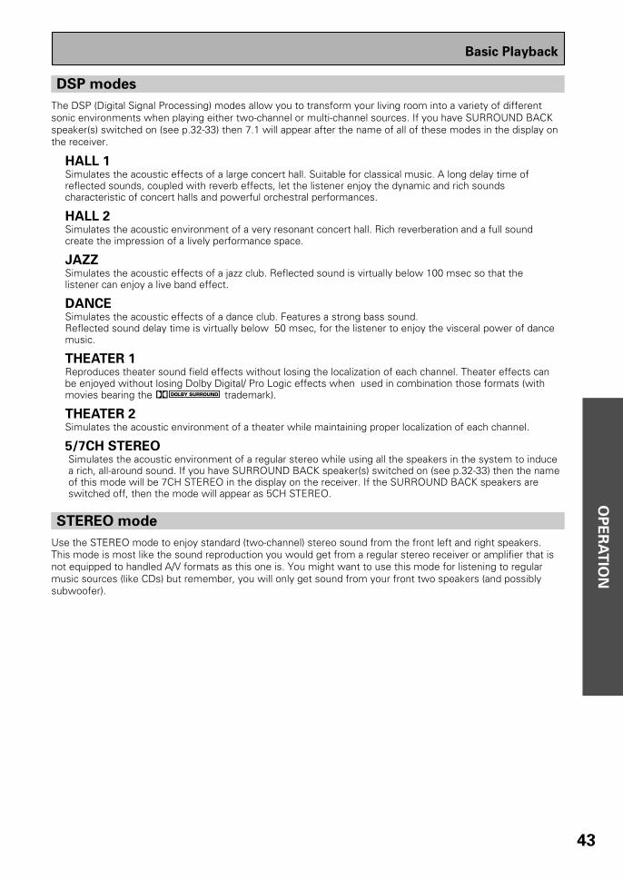
OP
ER
AT
ION
43
DSP modes
The DSP (Digital Signal Processing) modes allow you to transform your living room into a variety of differentsonic environments when playing either two-channel or multi-channel sources. If you have SURROUND BACKspeaker(s) switched on (see p.32-33) then 7.1 will appear after the name of all of these modes in the display onthe receiver.
HALL 1Simulates the acoustic effects of a large concert hall. Suitable for classical music. A long delay time ofreflected sounds, coupled with reverb effects, let the listener enjoy the dynamic and rich soundscharacteristic of concert halls and powerful orchestral performances.
HALL 2Simulates the acoustic environment of a very resonant concert hall. Rich reverberation and a full soundcreate the impression of a lively performance space.
JAZZSimulates the acoustic effects of a jazz club. Reflected sound is virtually below 100 msec so that thelistener can enjoy a live band effect.
DANCESimulates the acoustic effects of a dance club. Features a strong bass sound.Reflected sound delay time is virtually below 50 msec, for the listener to enjoy the visceral power of dancemusic.
THEATER 1Reproduces theater sound field effects without losing the localization of each channel. Theater effects canbe enjoyed without losing Dolby Digital/ Pro Logic effects when used in combination those formats (withmovies bearing the DOLBY SURROUND trademark).
THEATER 2Simulates the acoustic environment of a theater while maintaining proper localization of each channel.
5/7CH STEREO Simulates the acoustic environment of a regular stereo while using all the speakers in the system to induce a rich, all-around sound. If you have SURROUND BACK speaker(s) switched on (see p.32-33) then the name of this mode will be 7CH STEREO in the display on the receiver. If the SURROUND BACK speakers are switched off, then the mode will appear as 5CH STEREO.
STEREO mode
Use the STEREO mode to enjoy standard (two-channel) stereo sound from the front left and right speakers.This mode is most like the sound reproduction you would get from a regular stereo receiver or amplifier that isnot equipped to handled A/V formats as this one is. You might want to use this mode for listening to regularmusic sources (like CDs) but remember, you will only get sound from your front two speakers (and possiblysubwoofer).
Basic Playback
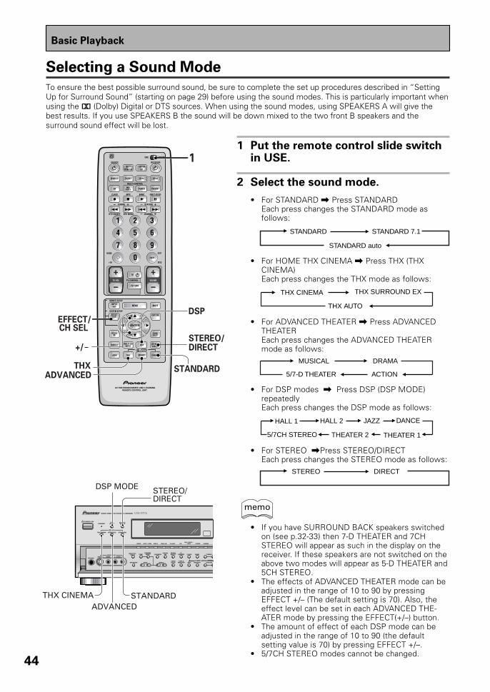
44
Selecting a Sound Mode
To ensure the best possible surround sound, be sure to complete the set up procedures described in “SettingUp for Surround Sound” (starting on page 29) before using the sound modes. This is particularly important whenusing the 2 (Dolby) Digital or DTS sources. When using the sound modes, using SPEAKERS A will give thebest results. If you use SPEAKERS B the sound will be down mixed to the two front B speakers and thesurround sound effect will be lost.
AV PRE-PROGRAMMED AND LEARNINGREMOTE CONTROL UNIT
S0URCE
DVD/LD TV/SAT VCR1 VCR2
CD
TV VOL
TV FUNC
MENU
ENTER
STEREO/DIRECTDSP
THXLIGHT
MUTE
TV
VOLUME
MD/TAPE1 TUNER TVCONT
RECEIVER
USE SETUP
MULTIOPERATION
CLASS MPX DIRECT ACCESS
CHANNEL
STATION
TV CONTROL
FUNCTION
REMOTE SETUP
SYSTEM SETUP
INPUTATT
MIDNIGHT MULTI CHINPUT
STANDARD
DIGITALNR
EFFECT/CH SEL
SIGNALSELECT
BAND
SYSTEMOFF
1 2 3
4 5 6
7 8 9
0
Î
¶ 87 3
1 ¡ 4 ¢ +-
+-
+-
MULTI CONTROL
+ +
– –
+
–STEREO/DIRECT
STANDARDADVANCED
THX
+/
EFFECT/DSP
ADVANCED
DISC
EXIT
+10
GUIDE
ENTER
/DTS
CH SEL
DTV ON/OFF DTV MENU
TUNING
1
Basic Playback
1 Put the remote control slide switchin USE.
2 Select the sound mode.
• For STANDARD \ Press STANDARDEach press changes the STANDARD mode asfollows:
STANDARD STANDARD 7.1
STANDARD auto
• For HOME THX CINEMA \ Press THX (THXCINEMA)Each press changes the THX mode as follows:
THX CINEMA THX SURROUND EX
THX AUTO
• For ADVANCED THEATER \ Press ADVANCEDTHEATEREach press changes the ADVANCED THEATERmode as follows:
MUSICAL DRAMA
ACTION5/7-D THEATER
• For DSP modes \ Press DSP (DSP MODE)repeatedlyEach press changes the DSP mode as follows:
HALL 1 HALL 2 JAZZ
5/7CH STEREO THEATER 2 THEATER 1
DANCE
• For STEREO \Press STEREO/DIRECTEach press changes the STEREO mode as follows:
STEREO DIRECT
• If you have SURROUND BACK speakers switchedon (see p.32-33) then 7-D THEATER and 7CHSTEREO will appear as such in the display on thereceiver. If these speakers are not switched on theabove two modes will appear as 5-D THEATER and5CH STEREO.
• The effects of ADVANCED THEATER mode can beadjusted in the range of 10 to 90 by pressingEFFECT +/– (The default setting is 70). Also, theeffect level can be set in each ADVANCED THE-ATER mode by pressing the EFFECT(+/–) button.
• The amount of effect of each DSP mode can beadjusted in the range of 10 to 90 (the defaultsetting value is 70) by pressing EFFECT +/–.
• 5/7CH STEREO modes cannot be changed.
memoSTANDBY/ON DSP
MODE
THX CINEMA ADVANCED STANDARD
STANDBY
AUDIO/VIDEO MULTI-CHANNEL RECEIVER
STEREO/DIRECT
/DTS
N∫m¿≤≥ım
PHONES S-VIDEO VIDEO
MULTI CH INPUT
SIGNALSELECT
FLDIMMER
TAPE 2MONITOR
TONECHANNEL
SELECT LOUDNESSDIGITAL
NR CLASS BAND
TUNER CONTROLMEMORYMPX
VIDEOSELCTSPEAKERS
- TUNING +
- STATION +- TREBLE +- BASS +
L AUDIO RVIDEO INPUT
VIDEO VCR 1/DVR VCR 2 DVD/LD TV/SATMD/TAPE1/
CD-R TUNERCD PHONO
DSP MODE STEREO/DIRECT
STANDARDTHX CINEMAADVANCED

OP
ER
AT
ION
45
1 Turn on the power of the playback
component.
2 Put the remote control slide switch in USE.
3 Press the RECEIVER button to turn on the
receiver.Be sure that the standby indicator turns off on the front panel.
4 Press the MULTI CONTROL buttons or the
FUNCTION button to select the source you
want to playback.The FUNCTION button cycles through the sources in thefollowing order:
5 Choose a sound mode by pressing THX,
ADVANCED or STANDARD.The default setting is STEREO.
(For more see “Sound Modes” and “Selecting a Sound Mode“on pages 41-44.)
6 Press the SIGNAL SELECT button to select
the input signal. Set to AUTO.(See “Switching Analog and Digital Signal Input” on page 47.)
7 Start playback of the component you
selected in step 1.
8 Adjust the volume by using the volume
buttons on the remote control or the
MASTER VOLUME on the front panel.
• We recommend using different modes for different types ofDTS material. For watching movies, the STANDARD, THX orADVANCED THEATER setting should provide the best results.For listening to music, the STANDARD, DIRECT, STEREO, orDSP modes should serve the listener best.
• Make sure you connect your DVD/LD or LD players using the2 RF jack. If your player has an 2 RF output this will ensureyou can use all LDs. Refer to p.14.
memo
AV PRE-PROGRAMMED AND LEARNINGREMOTE CONTROL UNIT
S0URCE
DVD/LD TV/SAT VCR1 VCR2
CD
TV VOL
TV FUNC
MENU
ENTER
STEREO/DIRECTDSP
THXLIGHT
MUTE
TV
VOLUME
MD/TAPE1 TUNER TVCONT
RECEIVER
USE SETUP
MULTIOPERATION
CLASS MPX DIRECT ACCESS
CHANNEL
STATION
TV CONTROL
FUNCTION
REMOTE SETUP
SYSTEM SETUP
INPUTATT
MIDNIGHT MULTI CHINPUT
STANDARD
DIGITALNR
EFFECT/CH SEL
SIGNALSELECT
BAND
SYSTEMOFF
1 2 3
4 5 6
7 8 9
0
Î
¶ 87 3
1 ¡ 4 ¢ +-
+-
+-
MULTI CONTROL
+ +
– –
+
–
ADVANCED
DISC
EXIT
+10
GUIDE
ENTER
/DTS
234
6
5
4
8
DTV ON/OFF DTV MENU
TUNING
STANDBY/ON DSPMODE
MULTI-ROOM&SOURCE
INPUTSELECTOR
MASTERVOLUME
MIN MAX
THX CINEMA ADVANCED STANDARD CONTROL
STANDBY
AUDIO/VIDEO MULTI-CHANNEL RECEIVER
STEREO/DIRECT
/DTS
N∫m¿≤≥ım
PHONES S-VIDEO VIDEO
MULTI CH INPUT
SIGNALSELECT
FLDIMMER
TAPE 2MONITOR
TONECHANNEL
SELECT LOUDNESSDIGITAL
NR CLASS BAND
TUNER CONTROLMEMORYMPX
VIDEOSELCTSPEAKERS
- TUNING +
- STATION +- TREBLE +- BASS +
L AUDIO RVIDEO INPUT
VIDEO VCR 1/DVR VCR 2 DVD/LD TV/SATMD/TAPE1/
CD-R TUNERCD PHONO
3 45 6
8
Basic Playback
Playing Sources with Dolby Digital or DTS Sound
The following instructions show you how to play Dolby Digital or DTS sound sources with the VSX-37TX/36TX.
TUNERMD
VCR 2 VCR 1
TV/SATDVD/LD
VIDEO
CD
PHONO

46
Playing Stereo Sources
The following instructions show you how to use the receiver for stereo audio or audio-visual.
If the TAPE 2 indicator is visible in the display, it means the TAPE 2 MONITOR is on. Press TAPE 2MONITOR on the front panel to turn it off unless you want to listen to TAPE 2.
1 Turn on the power of the playback
component.
2 Put the remote control slide switch in USE.
3 Press the RECEIVER button to turn on
the receiver.Be sure that the standby indicator turns off on the frontpanel.
4 Press the MULTI CONTROL buttons or the
FUNCTION button to select the source you
want to playback.The FUNCTION button cycles through the sources in thefollowing order:
5 Press the STEREO/DIRECT button to select
the stereo mode.The STEREO indicator lights on the display.
6 Press the SIGNAL SELECT button to select
the input signal corresponding to the
source component.(See “Switching Analog and Digital Signal Input” on page 47.)
7 Start playback of the component you
selected in step 1.
8 Adjust the volume by using the VOLUME
buttons on the remote control or the
MASTER VOLUME on the front panel.
If you are not able to get sound from the receiver theproblem may well lie with the SIGNAL SELECT switch.You need to make sure the input is set to the appropriateANALOG or DIGITAL setting. Refer to page 47 for moreon this.
memo
AV PRE-PROGRAMMED AND LEARNINGREMOTE CONTROL UNIT
S0URCE
DVD/LD TV/SAT VCR1 VCR2
CD
TV VOL
TV FUNC
MENU
ENTER
STEREO/DIRECTDSP
THXLIGHT
MUTE
TV
VOLUME
MD/TAPE1 TUNER TVCONT
RECEIVER
USE SETUP
MULTIOPERATION
CLASS MPX DIRECT ACCESS
CHANNEL
STATION
TV CONTROL
FUNCTION
REMOTE SETUP
SYSTEM SETUP
INPUTATT
MIDNIGHT MULTI CHINPUT
STANDARD
DIGITALNR
EFFECT/CH SEL
SIGNALSELECT
BAND
SYSTEMOFF
1 2 3
4 5 6
7 8 9
0
Î
¶ 87 3
1 ¡ 4 ¢ +-
+-
+-
MULTI CONTROL
+ +
– –
+
–
ADVANCED
DISC
EXIT
+10
GUIDE
ENTER
/DTS
234
6
5
4
8
DTV ON/OFF DTV MENU
TUNING
STANDBY/ON DSPMODE
MULTI-ROOM&SOURCE
INPUTSELECTOR
MASTERVOLUME
MIN MAX
THX CINEMA ADVANCED STANDARD CONTROL
STANDBY
AUDIO/VIDEO MULTI-CHANNEL RECEIVER
STEREO/DIRECT
/DTS
N∫m¿≤≥ım
PHONES S-VIDEO VIDEO
MULTI CH INPUT
SIGNALSELECT
FLDIMMER
TAPE 2MONITOR
TONECHANNEL
SELECT LOUDNESSDIGITAL
NR CLASS BAND
TUNER CONTROLMEMORYMPX
VIDEOSELCTSPEAKERS
- TUNING +
- STATION +- TREBLE +- BASS +
L AUDIO RVIDEO INPUT
VIDEO VCR 1/DVR VCR 2 DVD/LD TV/SATMD/TAPE1/
CD-R TUNERCD PHONO
3 46
8
5
Basic Playback
TUNERMD
VCR 2 VCR 1
TV/SATDVD/LD
VIDEO
CD
PHONO
memo

OP
ER
AT
ION
47
Switching Analog and Digital Signal Input
This switch moves the input fed to the receiver between analog, digital and 2 RF sources. You need to takespecial care to switch to the appropriate input, when necessary. For example, the switch would have to be onDIGITAL to use DOLBY DIGITAL or DTS surround sound but it would have to be on ANALOG to record to theanalog out jacks on the receiver. The default setting is AUTO (priority is given to a digital signal, if there is one).
1 Put the remote control slide switch in USE.
2 Press the SIGNAL SELECT button to select
the input signal corresponding to the
source component.Each press switches the signal in the order below:
VSX-37TX model
AUTO
AC-3RF
ANALOG
DIGITAL
VSX-36TX model
3 While SIGNAL SELECT is set to DIGITAL, AC-3
lights when a Dolby Digital signal is input,
DTS lights when a DTS signal is input.
• In the AUTO setting, SIGNAL SELECT chooses the signal in the following order: AC-3 RF (VSX-37TX only),DIGITAL, ANALOG.
• If the Digital-In Select (see page 31) choices are set to OFF, the SIGNAL SELECT will default to ANALOG.• Because the audio from a karaoke microphone and LD recorded with analog audio only is not output from
the digital output, set SIGNAL SELECT to ANALOG.• This receiver can only playback Dolby Digital, PCM (32kHz, 44kHz, 48kHz, and 96kHz), and DTS digital
signal formats. If you have some equipment that outputs digital audio in a format other than these you'llhave to connect and playback via the receiver's analog inputs (make sure that SIGNAL SELECT is set toANALOG).
• When an LD or CD with DTS is played back with the SIGNAL SELECT set in ANALOG, digital noise causedby playing back the DTS directly (with no decoding) is output. To prevent noise, you need to make digitalconnections (See pages 13 and 14) and set SIGNAL SELECT to DIGITAL or AUTO.
• Some DVD players don’t output DTS signals. For more details, refer to the instruction manual supplied withyour DVD player.
memo
AV PRE-PROGRAMMED AND LEARNINGREMOTE CONTROL UNIT
S0URCE
DVD/LD TV/SAT VCR1 VCR2
CD
TV VOL
TV FUNC
MENU
ENTER
STEREO/DIRECTDSP
THXLIGHT
MUTE
TV
VOLUME
MD/TAPE1 TUNER TVCONT
RECEIVER
USE SETUP
MULTIOPERATION
CLASS MPX DIRECT ACCESS
CHANNEL
STATION
TV CONTROL
FUNCTION
REMOTE SETUP
SYSTEM SETUP
INPUTATT
MIDNIGHT MULTI CHINPUT
STANDARD
DIGITALNR
EFFECT/CH SEL
SIGNALSELECT
BAND
SYSTEMOFF
1 2 3
4 5 6
7 8 9
0
Î
¶ 87 3
1 ¡ 4 ¢ +-
+-
+-
MULTI CONTROL
+ +
– –
+
–
1
2
ADVANCED
DISC
EXIT
+10
GUIDE
ENTER
/DTS
DTV ON/OFF DTV MENU
TUNING
STANDBY/ON DSPMODE
MULTI-ROOM&SOURCE
INPUTSELECTOR
MASTERVOLUME
MIN MAX
THX CINEMA ADVANCED STANDARD CONTROL
STANDBY
AUDIO/VIDEO MULTI-CHANNEL RECEIVER
STEREO/DIRECT
/DTS
N∫m¿≤≥ım
PHONES S-VIDEO VIDEO
MULTI CH INPUT
SIGNALSELECT
FLDIMMER
TAPE 2MONITOR
TONECHANNEL
SELECT LOUDNESSDIGITAL
NR CLASS BAND
TUNER CONTROLMEMORYMPX
VIDEOSELCTSPEAKERS
- TUNING +
- STATION +- TREBLE +- BASS +
L AUDIO RVIDEO INPUT
VIDEO VCR 1/DVR VCR 2 DVD/LD TV/SATMD/TAPE1/
CD-R TUNERCD PHONO
2
Basic Playback
SIGNALSELECT
DTS
SP ADIGITAL
SIGNALSELECT
AC-3
SP ADIGITAL
SIGNALSELECT
DTS
DIGITAL
SIGNALSELECT
AC-3
DIGITAL
When a DTS signal isinput.
When a Dolby Digitalsignal is input.
AUTO ANALOG
DIGITAL

48
1 Put the remote control slide switch in USE.
2 Press the DIGITAL NR button on the remote
control or on the front panel.Each press switches DIGITAL NR on or off.
dB
STEREOSIGNALSELECT
SP ADIGITAL
VOLUME
j dB
STEREOSIGNALSELECT
SP ADIGITAL
VOLUME
• In cases described below, noises may not be reduced even ifDIGITAL NR is on.
• Sudden noise• Extremely loud noise• Signals that do not contain many high frequencies
• DIGITAL NR is effective at and above levels shown below foreach source.
• STEREO (excluding 96 kHz)• analog input ..................................................... 10 -18 dB
• digital input ...................................................... 10 -15 dB
• AM/FM tuner .................................................. 10 -15 dB• DSP/ADVANCED/STANDARD/96 kHz stereo .... 6 -10 dB
• Depending on the condition of the source, there may not be anoticeable improvement in the quality of the sound.
• You can’t use the DIGITAL NR mode with the THX or MULTICH IN modes.
• If you press DIGITAL NR when in DIRECT mode the receiverswitches to STEREO mode.
Reducing Noise During Playback
To reduce extraneous noise switch on DIGITAL NR. This noise reduction can be used with every mode exceptTHX and MULTI CH IN.
AV PRE-PROGRAMMED AND LEARNINGREMOTE CONTROL UNIT
S0URCE
DVD/LD TV/SAT VCR1 VCR2
CD
TV VOL
TV FUNC
MENU
ENTER
STEREO/DIRECTDSP
THXLIGHT
MUTE
TV
VOLUME
MD/TAPE1 TUNER TVCONT
RECEIVER
USE SETUP
MULTIOPERATION
CLASS MPX DIRECT ACCESS
CHANNEL
STATION
TV CONTROL
FUNCTION
REMOTE SETUP
SYSTEM SETUP
INPUTATT
MIDNIGHT MULTI CHINPUT
STANDARD
DIGITALNR
EFFECT/CH SEL
SIGNALSELECT
BAND
SYSTEMOFF
1 2 3
4 5 6
7 8 9
0
Î
¶ 87 3
1 ¡ 4 ¢ +-
+-
+-
MULTI CONTROL
+ +
– –
+
–
1
2
ADVANCED
DISC
EXIT
+10
GUIDE
ENTER
/DTS
DTV ON/OFF DTV MENU
TUNING
STANDBY/ON DSPMODE
MULTI-ROOM&SOURCE
INPUTSELECTOR
MASTERVOLUME
MIN MAX
THX CINEMA ADVANCED STANDARD CONTROL
STANDBY
AUDIO/VIDEO MULTI-CHANNEL RECEIVER
STEREO/DIRECT
/DTS
N∫m¿≤≥ım
PHONES S-VIDEO VIDEO
MULTI CH INPUT
SIGNALSELECT
FLDIMMER
TAPE 2MONITOR
TONECHANNEL
SELECT LOUDNESSDIGITAL
NR CLASS BAND
TUNER CONTROLMEMORYMPX
VIDEOSELCTSPEAKERS
- TUNING +
- STATION +- TREBLE +- BASS +
L AUDIO RVIDEO INPUT
VIDEO VCR 1/DVR VCR 2 DVD/LD TV/SATMD/TAPE1/
CD-R TUNERCD PHONO
2
Basic Playback
memo

OP
ER
AT
ION
49
Listening in Midnight Mode
This feature makes it possible to get excellent surround sound effects even when listening at low volumes. Itcan be used with a variety of surround sound sources and plays soundtracks so that the quieter sounds areaudible while the noisier sounds don’t become overly loud or distorted. It does this by bringing all the sounds ina given soundtrack closer together in volume. Compare this feature with the D-Range Control (only for DolbyDigital sources) on page 39.
1 Put the remote control slide switch in USE.
2 Press the MIDNIGHT button.Each press switches MIDNIGHT LISTENING mode on or off.
• The effect adjusts itself automatically in accordance withthe volume level.
• You can’t use the MIDNIGHT LISTENING mode with theTHX or MULTI CH IN modes.
• If you press MIDNIGHT when in DIRECT mode the receiverswitches to STEREO mode.
memo
dB
STEREOMIDNIGHTSIGNALSELECT
SP ADIGITAL
AUTO
VOLUME
Basic Playback
Listening the Loudness Mode
The LOUDNESS mode allows you to boost the bass in a signal. It is useful for listening to music at low volumes.
dB
STEREOLOUDNESSSIGNALSELECTANALOG SP A
AUTO
VOLUME
Press the LOUDNESS button.Each press switches LOUDNESS mode between on and off.
• You can’t use the LOUDNESS mode with the MULTI CH INor THX modes.
• If you press LOUDNESS in DIRECT mode the receiver willswitch to STEREO mode.
memo
STANDBY/ON DSPMODE
MULTI-ROOM&SOURCE
INPUTSELECTOR
MASTERVOLUME
MIN MAX
THX CINEMA ADVANCED STANDARD CONTROL
STANDBY
AUDIO/VIDEO MULTI-CHANNEL RECEIVER
STEREO/DIRECT
/DTS
N∫m¿≤≥ım
PHONES S-VIDEO VIDEO
MULTI CH INPUT
SIGNALSELECT
FLDIMMER
TAPE 2MONITOR
TONECHANNEL
SELECT LOUDNESSDIGITAL
NR CLASS BAND
TUNER CONTROLMEMORYMPX
VIDEOSELCTSPEAKERS
- TUNING +
- STATION +- TREBLE +- BASS +
L AUDIO RVIDEO INPUT
VIDEO VCR 1/DVR VCR 2 DVD/LD TV/SATMD/TAPE1/
CD-R TUNERCD PHONO
LOUDNESS
AV PRE-PROGRAMMED AND LEARNINGREMOTE CONTROL UNIT
S0URCE
DVD/LD TV/SAT VCR1 VCR2
CD
TV VOL
TV FUNC
MENU
ENTER
STEREO/DIRECTDSP
THXLIGHT
MUTE
TV
VOLUME
MD/TAPE1 TUNER TVCONT
RECEIVER
USE SETUP
MULTIOPERATION
CLASS MPX DIRECT ACCESS
CHANNEL
STATION
TV CONTROL
FUNCTION
REMOTE SETUP
SYSTEM SETUP
INPUTATT
MIDNIGHT MULTI CHINPUT
STANDARD
DIGITALNR
EFFECT/CH SEL
SIGNALSELECT
BAND
SYSTEMOFF
1 2 3
4 5 6
7 8 9
0
Î
¶ 87 3
1 ¡ 4 ¢ +-
+-
+-
MULTI CONTROL
+ +
– –
+
–
1
2ADVANCED
DISC
EXIT
+10
GUIDE
ENTER
/DTS
DTV ON/OFF DTV MENU
TUNING

50
Adjusting Bass and Treble
You can use BASS +/– or TREBLE +/– buttons to adjust the low and high frequencies for each individual set ofspeakers. If the receiver is in STEREO mode you can only adjust the FRONT speakers. In a surround mode(STANDARD, ADVANCED THEATER, etc.) you can adjust the FRONT, CENTER, SURROUND and SURROUNDBACK speakers. The TONE button can also be used to bypass the tone circuitry (see p.22).
1 Press the TONE button on the front panel toput the receiver in tone TONE: ON mode.
2 Press the CHANNEL SELECT button on thefront panel to cycle through the differenttone adjust modes.The button cycles though the possibilities in the followingorder:
TONE Front TONE Center
TONE SurBack TONE Surr.
3 Use the BASS or TREBLE (+/–) buttons toadjust the low or high frequencies of eachchannel.
dB
STEREOSIGNALSELECTANALOG SP A
VOLUME
A few seconds after you finish adjusting the tone the receiver willrevert to the sound mode it was in at the beginning of theprocess.
• The tone control can be adjusted in a range of ±6 dB.• The tone control cannot be adjusted in THX and MULTI CH
IN modes.• If the receiver is in DIRECT mode and you press the TONE
button, TONE BYPASS will appear in the display, letting youknow that you can't change the tone in DIRECT mode. An-other press cancels DIRECT mode.
memo
STANDBY/ON DSPMODE
MULTI-ROOM&SOURCE
INPUTSELECTOR
MASTERVOLUME
MIN MAX
THX CINEMA ADVANCED STANDARD CONTROL
STANDBY
AUDIO/VIDEO MULTI-CHANNEL RECEIVER
STEREO/DIRECT
/DTS
N∫m¿≤≥ım
PHONES S-VIDEO VIDEO
MULTI CH INPUT
SIGNALSELECT
FLDIMMER
TAPE 2MONITOR
TONECHANNEL
SELECT LOUDNESSDIGITAL
NR CLASS BAND
TUNER CONTROLMEMORYMPX
VIDEOSELCTSPEAKERS
- TUNING +
- STATION +- TREBLE +- BASS +
L AUDIO RVIDEO INPUT
VIDEO VCR 1/DVR VCR 2 DVD/LD TV/SATMD/TAPE1/
CD-R TUNERCD PHONO
2
3
1
Basic Playback

OP
ER
AT
ION
51
Basic Playback
MULTI CHANNEL IN Playback
MULTI CH IN allows you to connect an external decoder to enjoy certain types of specialized discs. To useMULTI CH IN playback follow the instructions below.
memo
1 Put the remote control slide switch in USE.
2 Press the MULTI CH INPUT button on theremote control or the front panel.Each press switches the input between the previous mode andMULTI CH IN.
dB
SIGNALSELECTANALOG SP A
VOLUME
When MULTI CH IN is used in BYPASS mode only the volumelevel can be set. All of this unit’s other features (DIGITAL NRetc.) cannot be used. Also, all speaker settings and other setupsettings have no effect.
STANDBY/ON DSPMODE
MULTI-ROOM&SOURCE
INPUTSELECTOR
MASTERVOLUME
MIN MAX
THX CINEMA ADVANCED STANDARD CONTROL
STANDBY
AUDIO/VIDEO MULTI-CHANNEL RECEIVER
STEREO/DIRECT
/DTS
N∫m¿≤≥ım
PHONES S-VIDEO VIDEO
MULTI CH INPUT
SIGNALSELECT
FLDIMMER
TAPE 2MONITOR
TONECHANNEL
SELECT LOUDNESSDIGITAL
NR CLASS BAND
TUNER CONTROLMEMORYMPX
VIDEOSELCTSPEAKERS
- TUNING +
- STATION +- TREBLE +- BASS +
L AUDIO RVIDEO INPUT
VIDEO VCR 1/DVR VCR 2 DVD/LD TV/SATMD/TAPE1/
CD-R TUNERCD PHONO
2AV PRE-PROGRAMMED AND LEARNING
REMOTE CONTROL UNIT
S0URCE
DVD/LD TV/SAT VCR1 VCR2
CD
TV VOL
TV FUNC
MENU
ENTER
STEREO/DIRECTDSP
THXLIGHT
MUTE
TV
VOLUME
MD/TAPE1 TUNER TVCONT
RECEIVER
USE SETUP
MULTIOPERATION
CLASS MPX DIRECT ACCESS
CHANNEL
STATION
TV CONTROL
FUNCTION
REMOTE SETUP
SYSTEM SETUP
INPUTATT
MIDNIGHT MULTI CHINPUT
STANDARD
DIGITALNR
EFFECT/CH SEL
BAND
SYSTEMOFF
1 2 3
4 5 6
7 8 9
0
Î
¶ 87 3
1 ¡ 4 ¢ +-
+-
+-
MULTI CONTROL
+ +
– –
+
–
1
2
ADVANCED
DISC
EXIT
+10
GUIDE
ENTER
/DTS
SIGNALSELECT
DTV ON/OFF DTV MENU
TUNING
96 kHz 24 bit Performance
This receiver is capable of playing back advanced DVD discs which are recorded in 96 kHz/24 bit format (theseare all stereo discs) and any source recorded in 96 kHz and up to 24 bit. The receiver will automatically read theformat of the source and play accordingly (of course the SIGNAL SELECT will have to set to AUTO or DIGITALto read the DVD soundtrack). When the receiver plays a 96 kHz disc “96 kHz“ and whatever mode you're using(for example “STEREO,“ “DIRECT“ or “DNR“) will appear in the display.
dB
STEREOSIGNALSELECT
SP ADIGITAL
AUTO
VOLUME • When a 96 kHz/24 bit disc is played back the volumemay be louder than that of a normal disc.
• Some DVD players cannot play 96 kHz/24 bit discs.Check the manual of your DVD player to make sure.
• During this playback the player enters the STEREOmode and you can use the controls available inSTEREO mode (LOUDNESS, MIDNIGHT, TONEcontrols, etc., see p.49-50).
• With 96 kHz/24 bit discs you are able to use MULTICH IN playback and the TAPE 2 MONITOR.
• In 96 kHz/24 bit mode you can't use the STANDARD,ADVANCED THEATER, THX, or DSP modes.
memo

52
Adjusting the Brightness of the Display
Use the FL DIMMER button to adjust the brightness of the fluorescent display (FL=fluorescent display).
Press the FL DIMMER button.Four levels of brightness ranging from very dim to very bright canbe selected. Each press changes the brightness of the display.When rotating through the options, the default brightness can alsobe selected.
Please note: it is a feature of this unit that the fluorescentdisplay will be brighter for a few seconds after you choose afunction (like DVD/LD, CD, etc.) and then get softer. This willstill happen when you adjust the brightness but the new set-ting will be the one the display softens to.
memo
Direct Playback
1 Put the remote control slide switch in USE.
2 Use the STEREO/DIRECT button to alternate
between STEREO or DIRECT mode (you can
also use the STEREO/DIRECT button on the
front panel).The DIRECT mode will give you the most accurate reproduction oftwo channel (stereo) sources but won't let you add any effects tothe sound.
• None of the tone controls or other sound modes can beused with DIRECT playback.
• If the receiver is in a different mode than STEREO to startwith the first push of the STEREO button will put it inSTEREO mode. After that the button will toggle the receiverbetween STEREO and DIRECT mode.
• For more on this button see the explanation of STEREOmode on p.43, 44, 46.
memo
STANDBY/ON DSPMODE
MULTI-ROOM&SOURCE
INPUTSELECTOR
MASTERVOLUME
MIN MAX
THX CINEMA ADVANCED STANDARD CONTROL
STANDBY
AUDIO/VIDEO MULTI-CHANNEL RECEIVER
STEREO/DIRECT
/DTS
N∫m¿≤≥ım
PHONES S-VIDEO VIDEO
MULTI CH INPUT
SIGNALSELECT
FLDIMMER
TAPE 2MONITOR
TONECHANNEL
SELECT LOUDNESSDIGITAL
NR CLASS BAND
TUNER CONTROLMEMORYMPX
VIDEOSELCTSPEAKERS
- TUNING +
- STATION +- TREBLE +- BASS +
L AUDIO RVIDEO INPUT
VIDEO VCR 1/DVR VCR 2 DVD/LD TV/SATMD/TAPE1/
CD-R TUNERCD PHONO
FL DIMMER
STANDBY/ON DSPMODE
MULTI-ROOM&SOURCE
INPUTSELECTOR
MASTERVOLUME
MIN MAX
THX CINEMA ADVANCED STANDARD CONTROL
STANDBY
AUDIO/VIDEO MULTI-CHANNEL RECEIVER
STEREO/DIRECT
/DTS
N∫m¿≤≥ım
PHONES S-VIDEO VIDEO
MULTI CH INPUT
SIGNALSELECT
FLDIMMER
TAPE 2MONITOR
TONECHANNEL
SELECT LOUDNESSDIGITAL
NR CLASS BAND
TUNER CONTROLMEMORYMPX
VIDEOSELCTSPEAKERS
- TUNING +
- STATION +- TREBLE +- BASS +
L AUDIO RVIDEO INPUT
VIDEO VCR 1/DVR VCR 2 DVD/LD TV/SATMD/TAPE1/
CD-R TUNERCD PHONO
2
S0URCE
DVD/LD TV/SAT VCR1 VCR2
CD MD/TAPE1 TUNER TVCONT
RECEIVER
USE SETUP
MULTIOPERATION
CLASS MPX DIRECT ACCESS
CHANNEL
STATION
BAND
SYSTEMOFF
1 2 3
Î
¶ 87 3
1 ¡ 4 ¢ +-
+-
+-
MULTI CONTROL
1
DTV ON/OFF DTV MENU
TUNING
This mode is for playing back a sound source in its purest form, no tone adjustments or other sound modes canbe used.
Basic Playback
dB
STEREOSIGNALSELECTANALOG SP A
VOLUME
AV PRE-PROGRAMMED AND LEARNINGREMOTE CONTROL UNIT
ENTER
STEREO/DIRECTDSP
THXLIGHT
FUNCTION
SYSTEM SETUP
MIDNIGHT MULTI CHINPUT
STANDARD
DIGITALNR
EFFECT/CH SEL
SIGNALSELECT
+
–
2ADVANCED
/DTS

OP
ER
AT
ION
53
DUAL MONO Setting
The dual mono setting can only be used when listening to Dolby Digital discs that have dual mono softwareencoded in them. Dual mono software usually is used to put two different soundtracks on one DVD. With thissetting you can choose which channel in the dual mono setting you want to listen to. Thus, it is useful forsoundtracks that have one language on one channel and a different language on the other. Remember thissetting is only applicable if you are using Dolby Digital software with dual mono and want to isolate one of thechannels therein. Otherwise, just ignore this function.
.
1 Put the receiver in STANDBY mode.
2 While holding down the VIDEO
SELECT button press the STANDBY/
ON button on the front panel.
3 You will see DUAL in the display for
about five seconds. During this time
use the STEREO/DIRECT button to
cycle through the different DUAL
MONO settings to find the one you
want.
The different settings are: DUAL ch1, where you onlyhear channel 1; DUAL ch2, where you only hear channel2; and DUAL ch1/ch2, where you hear both channels, butindependently from different speakers.
The default setting is DUAL ch1.
dB
STEREOSIGNALSELECTANALOG SP A
VOLUME
DUAL ch1 setting
dB
STEREOSIGNALSELECTANALOG SP A
VOLUME
dB
STEREOSIGNALSELECTANALOG SP A
VOLUME
DUAL ch2 setting
DUAL ch1/ch2 setting
STANDBY/ON DSPMODE
MULTI-ROOM&SOURCE
INPUTSELECTOR
MASTERVOLUME
MIN MAX
THX CINEMA ADVANCED STANDARD CONTROL
STANDBY
AUDIO/VIDEO MULTI-CHANNEL RECEIVER
STEREO/DIRECT
/DTS
N∫m¿≤≥ım
PHONES S-VIDEO VIDEO
MULTI CH INPUT
SIGNALSELECT
FLDIMMER
TAPE 2MONITOR
TONECHANNEL
SELECT LOUDNESSDIGITAL
NR CLASS BAND
TUNER CONTROLMEMORYMPX
VIDEOSELCTSPEAKERS
- TUNING +
- STATION +- TREBLE +- BASS +
L AUDIO RVIDEO INPUT
VIDEO VCR 1/DVR VCR 2 DVD/LD TV/SATMD/TAPE1/
CD-R TUNERCD PHONO
3 21,2
Basic Playback
When DUAL MONO isplaying with ch 1 selectedthe L will light. Whenplaying with ch 2 selectedthe R will light. Whenplaying with ch 1/2 selectedthe L and R will light.
DIGITALdB
SIGNALSELECT
AC-3
SP A
L
DIGITAL
VOLUME

54
Automatic and Manual Tuning
The following steps show you how to tune in FM and AM radio broadcasts using the automatic (search) andmanual (step) tuning functions. If you already know the exact frequency of the station you desire, see “DirectAccess Tuning“ on the following page.
1 Put the remote control slide switch in USE.
2 Press the TUNER button.On the remote, this selects the TUNER function on the receiverand sets the remote to the TUNER operation mode.
dB
STEREOSIGNALSELECTANALOG SP A
FM
VOLUME
3 Press BAND button on the remote control or
the front panel to select the band (FM or
AM).Each press switches the band: FM j AM
dB
STEREOSIGNALSELECTANALOG SP A
VOLUME
4 Tune in the station.For Automatic Tuning
Press and hold TUNING –/+ buttons for about one second, thenrelease.
The tuner starts searching the selected band and stop automat-ically at the first station it locates. Repeat to locate otherstations.
For Manual Tuning
• To change frequencies one step at a time, press TUNING –/+button repeatedly.
• To change frequencies quickly, hold down TUNING –/+button and release when you reach the frequency youdesire.
5 Adjust the MASTER VOLUME buttons on
the remote control or the MASTER VOLUME
on the front panel.
MPX Mode
If the TUNED or STEREO indicators do not light when tuning an FMstation, because the station is too far away or the broadcast signal isweak, press MPX button on the remote control or front panel to switchto MONO reception. This should improve reception enough for you toenjoy the broadcast.
STANDBY/ON DSPMODE
MULTI-ROOM&SOURCE
INPUTSELECTOR
MASTERVOLUME
MIN MAX
THX CINEMA ADVANCED STANDARD CONTROL
STANDBY
AUDIO/VIDEO MULTI-CHANNEL RECEIVER
STEREO/DIRECT
/DTS
N∫m¿≤≥ım
PHONES S-VIDEO VIDEO
MULTI CH INPUT
SIGNALSELECT
FLDIMMER
TAPE 2MONITOR
TONECHANNEL
SELECT LOUDNESSDIGITAL
NR CLASS BAND
TUNER CONTROLMEMORYMPX
VIDEOSELCTSPEAKERS
- TUNING +
- STATION +- TREBLE +- BASS +
L AUDIO RVIDEO INPUT
VIDEO VCR 1/DVR VCR 2 DVD/LD TV/SATMD/TAPE1/
CD-R TUNERCD PHONO
4 2
5
3
MPX
AV PRE-PROGRAMMED AND LEARNINGREMOTE CONTROL UNIT
S0URCE
DVD/LD TV/SAT VCR1 VCR2
CD
TV VOL
TV FUNC
MENU
ENTER
STEREO/DIRECTDSP
THXLIGHT
MUTE
TV
VOLUME
MD/TAPE1 TUNER TVCONT
RECEIVER
USE SETUP
MULTIOPERATION
CLASS MPX DIRECT ACCESS
CHANNEL
STATION
TV CONTROL
FUNCTION
REMOTE SETUP
SYSTEM SETUP
INPUTATT
MIDNIGHT MULTI CHINPUT
STANDARD
DIGITALNR
EFFECT/CH SEL
SIGNALSELECT
BAND
SYSTEMOFF
1 2 3
4 5 6
7 8 9
0
Î
¶ 87 3
1 ¡ 4 ¢ +-
+-
+-
MULTI CONTROL
+ +
– –
+
–
1
2
3MPX
4
5
ADVANCED
DISC
EXIT
+10
GUIDE
ENTER
/DTS
DTV ON/OFF DTV MENU
TUNING
Using the Tuner

OP
ER
AT
ION
55
Direct Access Tuning
The following steps show you how to tune directly to a specific frequency using the remote control.
1 Put the remote control slide switch in USE.
2 Press the TUNER button.This selects the TUNER function on the receiver and sets theremote to the TUNER operation mode.
3 Press the BAND button on the remote
control or the front panel to select the band
(FM or AM).Each press switches the band : FM j AM
4 Press DIRECT ACCESS button to activate
the direct Access tuning mode.The cursor blinks in the display on the front panel.
dB
STEREOSIGNALSELECTANALOG SP A
VOLUME
5 Use the NUMBER buttons to enter the
frequency of the station you want.Example:
To tune station 106.00 (FM), press:
1 = 0 = 6 = 0 = 0
dB
STEREOSIGNALSELECTANALOG SP A
STEREOTUNED
VOLUME
To cancel before inputting the frequency
Press DIRECT ACCESS button, and enter the frequency again.
6 Adjust the MASTER VOLUME buttons on
the remote control or the MASTER VOLUME
on the front panel.
AV PRE-PROGRAMMED AND LEARNINGREMOTE CONTROL UNIT
S0URCE
DVD/LD TV/SAT VCR1 VCR2
CD
TV VOL
TV FUNC
MENU
ENTER
STEREO/DIRECTDSP
THXLIGHT
MUTE
TV
VOLUME
MD/TAPE1 TUNER TVCONT
RECEIVER
USE SETUP
MULTIOPERATION
CLASS MPX DIRECT ACCESS
CHANNEL
STATION
TV CONTROL
FUNCTION
REMOTE SETUP
SYSTEM SETUP
INPUTATT
MIDNIGHT MULTI CHINPUT
STANDARD
DIGITALNR
EFFECT/CH SEL
SIGNALSELECT
BAND
SYSTEMOFF
1 2 3
4 5 6
7 8 9
0
Î
¶ 87 3
1 ¡ 4 ¢ +-
+-
+-
MULTI CONTROL
+ +
– –
+
–
1
243
5
6
ADVANCED
DISC
EXIT
+10
GUIDE
ENTER
/DTS
DTV ON/OFF DTV MENU
TUNING
Using the Tuner
STANDBY/ON DSPMODE
MULTI-ROOM&SOURCE
INPUTSELECTOR
MASTERVOLUME
MIN MAX
THX CINEMA ADVANCED STANDARD CONTROL
STANDBY
AUDIO/VIDEO MULTI-CHANNEL RECEIVER
STEREO/DIRECT
/DTS
N∫m¿≤≥ım
PHONES S-VIDEO VIDEO
MULTI CH INPUT
SIGNALSELECT
FLDIMMER
TAPE 2MONITOR
TONECHANNEL
SELECT LOUDNESSDIGITAL
NR CLASS BAND
TUNER CONTROLMEMORYMPX
VIDEOSELCTSPEAKERS
- TUNING +
- STATION +- TREBLE +- BASS +
L AUDIO RVIDEO INPUT
VIDEO VCR 1/DVR VCR 2 DVD/LD TV/SATMD/TAPE1/
CD-R TUNERCD PHONO
6
3

56
Memorizing Frequently Used Stations
The following steps show you how to memorize up to 30 radio stations in 3 classes (each holding 10 channels).When memorizing FM frequencies, the receiver also memorizes the MPX mode (STEREO or MONO).
1 Tune in the desired station.See "Automatic and Manual Tuning" or "Direct Access Tuning"on p.54 and 55.
2 Press the MEMORY button to activate the
memory function.
dB
STEREOSIGNALSELECTANALOG SP A
STEREOTUNED
VOLUME
3 Press the CLASS button repeatedly to select
a class number.Each press switches the display:
CLASS A CLASS B CLASS C
4 Press the STATION –/+ buttons repeatedly
to select a channel (0-9) within the
respective class.
dB
STEREOSIGNALSELECTANALOG SP A
STEREOTUNED
VOLUME
The station is memorized automatically after 5 seconds.
If you want to escape from MEMORY mode
Press the MEMORY button again.Repeat steps 1 through 4 to memorize up to 30 stations.
STANDBY/ON DSPMODE
MULTI-ROOM&SOURCE
INPUTSELECTOR
MASTERVOLUME
MIN MAX
THX CINEMA ADVANCED STANDARD CONTROL
STANDBY
AUDIO/VIDEO MULTI-CHANNEL RECEIVER
STEREO/DIRECT
/DTS
N∫m¿≤≥ım
PHONES S-VIDEO VIDEO
MULTI CH INPUT
SIGNALSELECT
FLDIMMER
TAPE 2MONITOR
TONECHANNEL
SELECT LOUDNESSDIGITAL
NR CLASS BAND
TUNER CONTROLMEMORYMPX
VIDEOSELCTSPEAKERS
- TUNING +
- STATION +- TREBLE +- BASS +
L AUDIO RVIDEO INPUT
VIDEO VCR 1/DVR VCR 2 DVD/LD TV/SATMD/TAPE1/
CD-R TUNERCD PHONO
43
2
Using the Tuner

OP
ER
AT
ION
57
Recalling Memorized Stations
Using the remote control
1 Put the remote control slide switch in USE.
2 Press the TUNER button.This selects the TUNER function on the receiver and sets theremote to the TUNER operation mode.
dB
STEREOSIGNALSELECTANALOG SP A
FM
VOLUME

58
1 Set the remote control slide switch to
SETUP.Also make sure that your TV is on and set to the receiver.
2 Press the REMOTE SETUP (INPUT ATT)
button.The REMOTE SET UP menu appears on your TV screen.
Select Remote Setup Mode
Remote SETUP+1 Preset RecallRemote SETUP+2 LearningRemote SETUP+3 Multi-OperationRemote SETUP+4 Direct Function
You have four setup options:
1 Preset Recall2 Learning
3 Multi Operation (See p.71)
4 Direct Function (See p.74)
Preset Recall and Learning are the two modes that teach theremote control to operate your other components. It's easiestto start with Preset Recall and, if setup isn't possible for certaincomponents, move on to the Learning mode.
3 Press the REMOTE SETUP button and 1 at
the same time to select the preset recall
setup mode.All the MULTI CONTROL buttons (except the TUNER button)start to blink.
To cancel the preset recall setup mode press REMOTE SET
UP.
Setting Up the Remote Control to Control Other
Components
In addition to controlling the receiver, the supplied remote control can operate your other components (VCR, TV,LD, CD, etc.) after you program it to do so. In this way, instead of fumbling with many different controls andbuttons, you only need to use one remote control. If your component(s) are listed in the remote control'smemory, simply follow the steps below. If your component(s) are not listed, or if you want the remote to learnadditional operations, you can use the learning mode to input the information from the remote controls suppliedwith your other components.
Recalling Preset Codes
The following steps show you how to recall preset codes stored in the remote control. Once a preset code isrecalled and the component assigned, you can use this remote to easily operate the component. See “PresetCode List“ on page 85 for the components and manufacturers available.
AV PRE-PROGRAMMED AND LEARNINGREMOTE CONTROL UNIT
ADVANCED
DISC
EXIT
+10
GUIDE
ENTER
/DTS
S0URCE
DVD/LD TV/SAT VCR1 VCR2
CD
TV VOL
TV FUNC
MENU
ENTER
STEREO/DIRECTDSP
THXLIGHT
MUTE
TV
VOLUME
MD/TAPE1 TUNER TVCONT
RECEIVER
USE SETUP
MULTIOPERATION
CLASS MPX DIRECT ACCESS
CHANNEL
STATION
TV CONTROL
FUNCTION
REMOTE SETUP
SYSTEM SETUP
INPUTATT
MIDNIGHT MULTI CHINPUT
STANDARD
DIGITALNR
EFFECT/CH SEL
SIGNALSELECT
BAND
SYSTEMOFF
1 2 3
4 5 6
7 8 9
0
Î
¶ 87 3
1 ¡ 4 ¢ +-
+-
+-
MULTI CONTROL
+ +
– –
+
–
1
3
2,3
ADVANCED
DISC
EXIT
+10
GUIDE
ENTER
/DTS
DTV ON/OFF DTV MENU
TUNING
Remote Control of Other Components
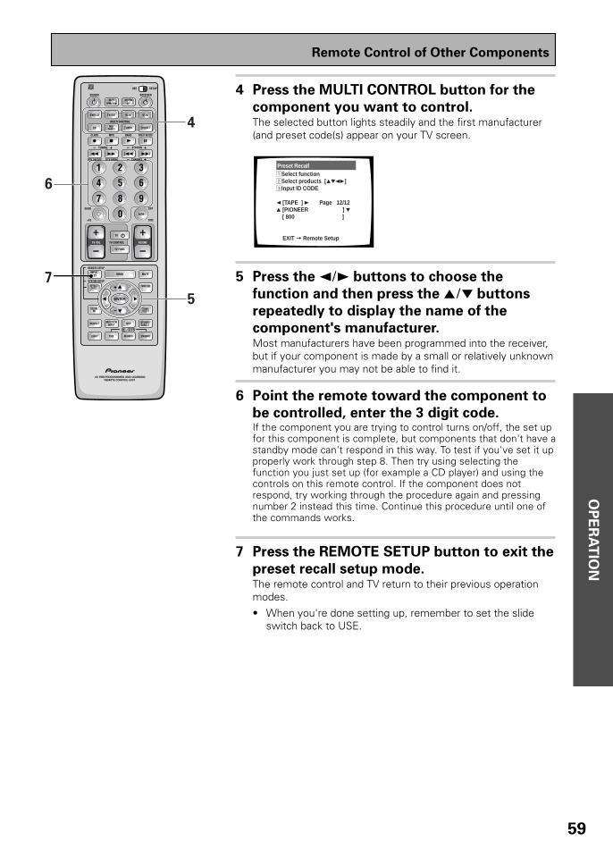
OP
ER
AT
ION
59
4 Press the MULTI CONTROL button for the
component you want to control.The selected button lights steadily and the first manufacturer(and preset code(s) appear on your TV screen.
Preset Recall1Select function2Select products [5∞23]3Input ID CODE
2 [TAPE ] 3 Page 12/12 5 [PIONEER ] ∞ [ 800 ]
EXIT = Remote Setup
5 Press the 2¥3 buttons to choose the
function and then press the 5¥∞ buttons
repeatedly to display the name of the
component's manufacturer.Most manufacturers have been programmed into the receiver,but if your component is made by a small or relatively unknownmanufacturer you may not be able to find it.
6 Point the remote toward the component to
be controlled, enter the 3 digit code.If the component you are trying to control turns on/off, the set upfor this component is complete, but components that don't have astandby mode can't respond in this way. To test if you've set it upproperly work through step 8. Then try using selecting thefunction you just set up (for example a CD player) and using thecontrols on this remote control. If the component does notrespond, try working through the procedure again and pressingnumber 2 instead this time. Continue this procedure until one ofthe commands works.
7 Press the REMOTE SETUP button to exit the
preset recall setup mode.The remote control and TV return to their previous operationmodes.• When you're done setting up, remember to set the slide
switch back to USE.
AV PRE-PROGRAMMED AND LEARNINGREMOTE CONTROL UNIT
S0URCE
DVD/LD TV/SAT VCR1 VCR2
CD
TV VOL
TV FUNC
MENU
ENTER
STEREO/DIRECTDSP
THXLIGHT
MUTE
TV
VOLUME
MD/TAPE1 TUNER TVCONT
RECEIVER
USE SETUP
MULTIOPERATION
CLASS MPX DIRECT ACCESS
CHANNEL
STATION
TV CONTROL
FUNCTION
REMOTE SETUP
SYSTEM SETUP
INPUTATT
MIDNIGHT MULTI CHINPUT
STANDARD
DIGITALNR
EFFECT/CH SEL
SIGNALSELECT
BAND
SYSTEMOFF
1 2 3
4 5 6
7 8 9
0
Î
¶ 87 3
1 ¡ 4 ¢ +-
+-
+-
MULTI CONTROL
+ +
– –
+
–
6
7
5
4
ADVANCED
DISC
EXIT
+10
GUIDE
ENTER
/DTS
DTV ON/OFF DTV MENU
TUNING
Remote Control of Other Components

60
Learning Commands from Other Remote Controls
If preset codes are not available for your component(s), or the available preset codes do not operate correctly,you can use this function to program in signals from the remote control(s) of your other component(s). Thisoperation can also be used after recalling a preset code to program additional operations not covered in thepreset codes.
1 Set the remote control slide switch to
SETUP.Also make sure that your TV is on and set to the receiver.
2 Press the REMOTE SETUP button.The REMOTE SET UP menu appears on your TV screen.
Select Remote Setup Mode
Remote SETUP+1 Preset RecallRemote SETUP+2 LearningRemote SETUP+3 Multi-OperationRemote SETUP+4 Direct Function
3 Press the REMOTE SETUP button and 2 at
the same time to select the learning setup
mode.All the MULTI CONTROL buttons (except the TUNER button)start to blink.
To cancel learning setup mode, press the REMOTE SET UP
button.
Learning Setup1Place both commanders pointing at each other.2Select the item from
the Multi-control buttons that should be duplicated. (ex. DVD)Multi-control button
starts blinking.
EXIT = Remote Setup
4 Press the MULTI CONTROL button for the
component you want to control.Each button can be set to control one of the following compo-nents.
The selected button continues to blink.
Learning Setup3Press one button that should be duplicated.4Multi-Contorol button lights up.5Press one button on the original commander, and hold 2 to 10 seconds. 6Repeat this process to duplicate next command. EXIT = Remote Setup
AV PRE-PROGRAMMED AND LEARNINGREMOTE CONTROL UNIT
S0URCE
DVD/LD TV/SAT VCR1 VCR2
CD
TV VOL
TV FUNC
MENU
ENTER
STEREO/DIRECTDSP
THXLIGHT
MUTE
TV
VOLUME
MD/TAPE1 TUNER TVCONT
RECEIVER
USE SETUP
MULTIOPERATION
CLASS MPX DIRECT ACCESS
CHANNEL
STATION
TV CONTROL
FUNCTION
REMOTE SETUP
SYSTEM SETUP
INPUTATT
MIDNIGHT MULTI CHINPUT
STANDARD
DIGITALNR
EFFECT/CH SEL
SIGNALSELECT
BAND
SYSTEMOFF
1 2 3
4 5 6
7 8 9
0
Î
¶ 87 3
1 ¡ 4 ¢ +-
+-
+-
MULTI CONTROL
+ +
– –
+
–
1
3
2,3
4
ADVANCED
DISC
EXIT
+10
GUIDE
ENTER
/DTS
DTV ON/OFF DTV MENU
TUNING
Remote Control of Other Components

OP
ER
AT
ION
61
5 Press the button to be programmed.The MULTI CONTROL button lights steadily.
• The TV POWER, TV FUNC and TV VOL +/– buttons are onlyavailable for learning when programming TV CONTROLoperations.
6 Point the remote controls at each other and
press the button on the other remote
control for the operation you wish to
program.
1 Point the remote controls toward each other.
2 Hold down the button on the other remote control corre-sponding to the operation you wish to program. Releasewhen the MULTI CONTROL button on the receiver's remotecontrol starts blinking.
(The MULTI CONTROL button blinks to indicate that theoperation has been learned.)To program additional operations for the current
component, repeat steps 5 and 6.
To program operations for another component, repeat
steps 4 through 6.
7 Press the REMOTE SETUP button to exit the
learning setup mode.The remote control and TV return to their previous operationmodes.
• When you're done setting up, remember to set the slideswitch back to USE.
AV PRE-PROGRAMMED AND LEARNINGREMOTE CONTROL UNIT
DTV ON/OFF DTV MENU
S0URCE
DVD/LD TV/SAT VCR1 VCR2
CD
TV VOL
TV FUNC
MENU
ENTER
STEREO/DIRECTDSP
THXLIGHT
MUTE
TV
VOLUME
MD/TAPE1 TUNER TVCONT
RECEIVER
USE SETUP
MULTIOPERATION
CLASS MPX DIRECT ACCESS
CHANNEL
STATION
TV CONTROL
FUNCTION
REMOTE SETUP
SYSTEM SETUP
INPUTATT
MIDNIGHT MULTI CHINPUT
STANDARD
DIGITALNR
EFFECT/CH SEL
SIGNALSELECT
BAND
SYSTEMOFF
1 2 3
4 5 6
7 8 9
0
Î
¶ 87 3
1 ¡ 4 ¢ +-
+-
+-
MULTI CONTROL
+ +
– –
+
–
5
7
ADVANCED
DISC
EXIT
+10
GUIDE
ENTER
/DTS
TUNING
Remote Control of Other Components
2-8 inches
(5-20 cm)

62
Using the Remote Control with Other Components
DVD or LD Player Operations
• The following operations are available from the receiver's remote control after you program your DVDor LD player's preset code, but some operations may need to be learned by the receiver (see “SettingUp the Remote Control to Control Other Components,“ on pages 58-61).
• To perform these operations, press the DVD/LD button to set the remote to the DVD or LD operationmode.
• For more information on individual commands consult the manual that came with the component.
1 SOURCEPress to switch the DVD or LD player on or off (not possiblewith all models, especially those without a standby mode).
2 7Press to stop playback.
3 ¶ (TOP MENU)Press to call up the menu programmed on the DVD ( for DVDonly).
4 1˜¡1 : Hold down for fast reverse playback.¡ : Hold down for fast forward playback.
5 Number buttonsUse to select chapters (tracks).
6 +10Use when selecting chapter (track) numbers higher than 10.
7 5˜∞˜2˜3˜ENTER5˜∞˜2˜3 : Use to navigate through options on menu screensand to change settings.ENTER : Use to implement settings selected with the cursorbuttons or to set items highlighted in a menu (for DVD only).
8 3Press to start playback.
9 8Press to pause playback.
0 4˜¢4 : Press to return to the beginning of the current chapter(track). Press repeatedly to return to the beginning of previouschapters (tracks).¢ : Press to advance to the beginning of the next chapter(track). Press repeatedly to advance to the beginning of follow-ing chapters (tracks).
- ENTER (SIDE A/B)Use to change the LD between sides A and B (for LD only).
= MENUPress to access a disc's menu.
AV PRE-PROGRAMMED AND LEARNINGREMOTE CONTROL UNIT
DTV ON/OFF DTV MENU
TUNING
S0URCE
DVD/LD TV/SAT VCR1 VCR2
CD
TV VOL
TV FUNC
MENU
ENTER
STEREO/DIRECTDSP
THXLIGHT
MUTE
TV
VOLUME
MD/TAPE1 TUNER TVCONT
RECEIVER
USE SETUP
MULTIOPERATION
CLASS MPX DIRECT ACCESS
CHANNEL
STATION
TV CONTROL
FUNCTION
REMOTE SETUP
SYSTEM SETUP
INPUTATT
MIDNIGHT MULTI CHINPUT
STANDARD
DIGITALNR
EFFECT/CH SEL
SIGNALSELECT
BAND
SYSTEMOFF
1 2 3
4 5 6
7 8 9
0
Î
¶ 87 3
1 ¡ 4 ¢ +-
+-
+-
MULTI CONTROL
+ +
– –
+
–
1
2
3
4
8
9
0
5
6
7
-
=
ADVANCED
DISC
EXIT
+10
GUIDE
ENTER
/DTS
Remote Control of Other Components

OP
ER
AT
ION
63
VCR & DVD Recorder Operations
• The following operations are available from the receiver's remote control after you program your VCRor DVD video recorder's preset code, but some operations may need to be learned by the receiver(see “Setting Up the Remote Control to Control Other Components,“ on pages 58-61).
• To perform these operations, press the VCR 1 or VCR 2 button to set the remote to the VCR, DVDvideo recorder operation mode.
• For more information on individual commands consult the manual that came with the component.
1 SOURCEPress to switch the VCR or DVD video recorder on or off (notpossible with all models, especially those without a standbymode).
2 7Press to stop playback.
3 ¶Press to start recording.
4 1˜¡1 : Hold down for fast reverse playback.
¡ : Hold down for fast forward playback.
5 Number buttonsUse to select channels.
6 +10Use when selecting chapter (track) numbers higher than 10 (forDVD video recorder only).
7 5˜∞˜2˜3˜ENTER5˜∞˜2˜3 : Use to navigate through options on menu screensand to change settings.
ENTER : Use to implement settings selected with the cursorbuttons or to set items highlighted in a menu (for DVD videorecorder only).
8 3Press to start playback.
9 8Press to pause playback.
0 CHANNEL –/+Use to change channels on the VCR's tuner.
- ENTER (TV/VCR)Use this button to switch the VCR between its tuner (forwatching videos) and the TV.
Press to stop recording (for DVD video recorder only).
= MENUUse to display or close the title menu screen (for DVD videorecorder only).
AV PRE-PROGRAMMED AND LEARNINGREMOTE CONTROL UNIT
DTV ON/OFF DTV MENU
TUNING
S0URCE
DVD/LD TV/SAT VCR1 VCR2
CD
TV VOL
TV FUNC
MENU
ENTER
STEREO/DIRECTDSP
THXLIGHT
MUTE
TV
VOLUME
MD/TAPE1 TUNER TVCONT
RECEIVER
USE SETUP
MULTIOPERATION
CLASS MPX DIRECT ACCESS
CHANNEL
STATION
TV CONTROL
FUNCTION
REMOTE SETUP
SYSTEM SETUP
INPUTATT
MIDNIGHT MULTI CHINPUT
STANDARD
DIGITALNR
EFFECT/CH SEL
SIGNALSELECT
BAND
SYSTEMOFF
1 2 3
4 5 6
7 8 9
0
Î
¶ 87 3
1 ¡ 4 ¢ +-
+-
+-
MULTI CONTROL
+ +
– –
+
–
1
2
3
4
8
9
0
5
6
7
-
=
ADVANCED
DISC
EXIT
+10
GUIDE
ENTER
/DTS
Remote Control of Other Components

64
CD & CD-R Player Operations
• The following operations are available from the receiver's remote control after you program your CDplayer or CD-R's preset code, but some operations may need to be learned by the receiver (see“Setting Up the Remote Control to Control Other Components,“ on pages 58-61).
• To perform these operations, press the CD button to set the remote to the CD operation mode.
• For more information on individual commands consult the manual that came with the component.
1 SOURCEPress to switch the CD player/recorder on or off (not possiblewith all models, especially those without a standby mode).
2 7Press to stop playback.
3 ¶Press to start recording (CD-R only).
4 1˜¡1 : Hold down for fast reverse playback.¡ : Hold down for fast forward playback.
5 Number buttonsUse to select channels.
6 +10Use when selecting chapter (track) numbers higher than 10.
7 3Press to start playback.
8 8Press to pause playback.
9 4˜¢4 : Press to return to the beginning of the current track.Press repeatedly to return to the beginning of previous tracks.
¢ : Press to advance to the beginning of the next track. Pressrepeatedly to advance to the beginning of following tracks.
0 DISCUse to switch between discs in file type disc play.
AV PRE-PROGRAMMED AND LEARNINGREMOTE CONTROL UNIT
DTV ON/OFF DTV MENU
TUNING
S0URCE
DVD/LD TV/SAT VCR1 VCR2
CD
TV VOL
TV FUNC
MENU
ENTER
STEREO/DIRECTDSP
THXLIGHT
MUTE
TV
VOLUME
MD/TAPE1 TUNER TVCONT
RECEIVER
USE SETUP
MULTIOPERATION
CLASS MPX DIRECT ACCESS
CHANNEL
STATION
TV CONTROL
FUNCTION
REMOTE SETUP
SYSTEM SETUP
INPUTATT
MIDNIGHT MULTI CHINPUT
STANDARD
DIGITALNR
EFFECT/CH SEL
SIGNALSELECT
BAND
SYSTEMOFF
1 2 3
4 5 6
7 8 9
0
Î
¶ 87 3
1 ¡ 4 ¢ +-
+-
+-
MULTI CONTROL
+ +
– –
+
–
1
2
3
4
7
8
9
5
6 0
ADVANCED
DISC
EXIT
+10
GUIDE
ENTER
/DTS
Remote Control of Other Components

OP
ER
AT
ION
65
MD Operations
• The following operations are available from the receiver's remote control after you program your MDrecorder's preset code, but some operations may need to be learned by the receiver (see “Setting upthe Remote Control to Control Other Components,“ on pages 58-61).
• To perform these operations, press the MD/TAPE 1 button to set the remote to the MD operationmode.
• For more information on individual commands consult the manual that came with the component.
1 SOURCEPress to switch the MD player on or off (not possible with allmodels, especially those without a standby mode).
2 7Press to stop playback or recording.
3 ¶Press to start recording (may put some decks in REC PAUSEmode).
4 1˜¡1 : Hold down for fast reverse playback.¡ : Hold down for fast forward playback.
5 Number buttonsUse to select tracks.
6 +10You can also use this button when selecting track numbershigher than 10. It's especially use for track numbers 11-19.
7 3Press to start playback.
8 8Press to pause playback.
9 4˜¢4 : Press to return to the beginning of the current track.Press repeatedly to return to the beginning of previous tracks.
¢ : Press to advance to the beginning of the next track. Pressrepeatedly to advance to the beginning of following tracks.
0 DISC (DISP/CHARA)Allows you to change the display mode of the MD.
AV PRE-PROGRAMMED AND LEARNINGREMOTE CONTROL UNIT
DTV ON/OFF DTV MENU
TUNING
S0URCE
DVD/LD TV/SAT VCR1 VCR2
CD
TV VOL
TV FUNC
MENU
ENTER
STEREO/DIRECTDSP
THXLIGHT
MUTE
TV
VOLUME
MD/TAPE1 TUNER TVCONT
RECEIVER
USE SETUP
MULTIOPERATION
CLASS MPX DIRECT ACCESS
CHANNEL
STATION
TV CONTROL
FUNCTION
REMOTE SETUP
SYSTEM SETUP
INPUTATT
MIDNIGHT MULTI CHINPUT
STANDARD
DIGITALNR
EFFECT/CH SEL
SIGNALSELECT
BAND
SYSTEMOFF
1 2 3
4 5 6
7 8 9
0
Î
¶ 87 3
1 ¡ 4 ¢ +-
+-
+-
MULTI CONTROL
+ +
– –
+
–
1
2
3
4
7
8
9
5
6 0
ADVANCED
DISC
EXIT
+10
GUIDE
ENTER
/DTS
Remote Control of Other Components

66
1 SOURCEPress to switch the satellite tuner on or off (not possible withall models, especially those without a standby mode).
2 ¶˜7˜3˜8˜1 (A/B/C/D/E)Use to make selections from Satellite functions.
3 Number buttonsUse to select satellite channels.
4 GUIDEUse to turn the program information screen on or off.
5 5˜∞˜2˜3˜ENTER5˜∞˜2˜3 : Press the button to select items on theSAT GUIDE screen or SAT MENU screen.
ENTER : Press to activate the selected function.
6 EXITPress to exit the current setting of the SAT.
7 MENUUse to turn the main menu on or off.
STB (satellite tuner) Operations
• The following operations are available from the receiver's remote control after you program yoursatellite tuner's (or cable TV's) preset code, but some operations may need to be learned by thereceiver (see “Setting Up the Remote Control to Control Other Components,“ on pages 58-61).
• To perform these operations, press the TV/SAT button to set the remote to the SAT operation mode.
• For more information on individual commands consult the manual that came with the component.
AV PRE-PROGRAMMED AND LEARNINGREMOTE CONTROL UNIT
DTV ON/OFF DTV MENU
TUNING
S0URCE
DVD/LD TV/SAT VCR1 VCR2
CD
TV VOL
TV FUNC
MENU
ENTER
STEREO/DIRECTDSP
THXLIGHT
MUTE
TV
VOLUME
MD/TAPE1 TUNER TVCONT
RECEIVER
USE SETUP
MULTIOPERATION
CLASS MPX DIRECT ACCESS
CHANNEL
STATION
TV CONTROL
FUNCTION
REMOTE SETUP
SYSTEM SETUP
INPUTATT
MIDNIGHT MULTI CHINPUT
STANDARD
DIGITALNR
EFFECT/CH SEL
SIGNALSELECT
BAND
SYSTEMOFF
1 2 3
4 5 6
7 8 9
0
Î
¶ 87 3
1 ¡ 4 ¢ +-
+-
+-
MULTI CONTROL
+ +
– –
+
–
1
2
3
4
5
6
7
ADVANCED
DISC
EXIT
+10
GUIDE
ENTER
/DTS
Remote Control of Other Components

OP
ER
AT
ION
67
TV Operations
• The following operations are available from the receiver's remote control after you program your TV'spreset code, but some operations may need to be learned by the receiver (see “Setting Up theRemote Control to Control Other Components,“ on pages 58-61).
• To perform these operations, press the TV/SAT and TV CONT button to set the remote to the TVoperation mode.
• For more information on individual commands consult the manual that came with the your TV.
1 SOURCEPress to switch the TV on or off (not possible with all models,especially those without a standby mode).
2 Number buttonsUse to select a specific TV channel.
3 ¶Use to select a specific TV channel.
4 5˜∞˜2˜3˜ENTER5˜∞˜2˜3˜ : Press to select or adjust items on themenu screen.
ENTER : Press to activate the selected function.
5 CHANNEL –/+Use to select a TV channel.
6 ENTER (CH ENTER)Use to select the channel specified with the number buttons(not all models require this step).
7 MENUPress to select the TV menu.
For Digital TVs:
8 ¶˜7˜3˜8˜1 (BLUE/GREEN/RED/
YELLOW)Use to make selections from the DTV menu.
9 1˜¡1 : Press to DTV mode on or off.¡ : Press to select the DTV menu.
AV PRE-PROGRAMMED AND LEARNINGREMOTE CONTROL UNIT
DTV ON/OFF DTV MENU
TUNING
S0URCE
DVD/LD TV/SAT VCR1 VCR2
CD
TV VOL
TV FUNC
MENU
ENTER
STEREO/DIRECTDSP
THXLIGHT
MUTE
TV
VOLUME
MD/TAPE1 TUNER TVCONT
RECEIVER
USE SETUP
MULTIOPERATION
CLASS MPX DIRECT ACCESS
CHANNEL
STATION
TV CONTROL
FUNCTION
REMOTE SETUP
SYSTEM SETUP
INPUTATT
MIDNIGHT MULTI CHINPUT
STANDARD
DIGITALNR
EFFECT/CH SEL
SIGNALSELECT
BAND
SYSTEMOFF
1 2 3
4 5 6
7 8 9
0
Î
¶ 87 3
1 ¡ 4 ¢ +-
+-
+-
MULTI CONTROL
+ +
– –
+
–
1
7
5
2
9
8
3
4
6
ADVANCED
DISC
EXIT
+10
GUIDE
ENTER
/DTS
Remote Control of Other Components
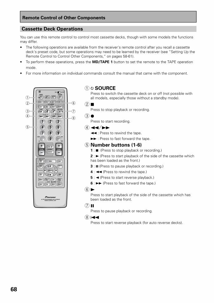
68
1 SOURCEPress to switch the cassette deck on or off (not possible withall models, especially those without a standby mode).
2 7Press to stop playback or recording.
3 ¶Press to start recording.
4 1˜¡1 : Press to rewind the tape.
¡ : Press to fast forward the tape.
5 Number buttons (1-6)1 : 7 (Press to stop playback or recording.)
2 : 3 (Press to start playback of the side of the cassette whichhas been loaded as the front.)
3 : 8 (Press to pause playback or recording.)4 : 1 (Press to rewind the tape.)
5 : 2 (Press to start reverse playback.)
6 : ¡ (Press to fast forward the tape.)
6 3Press to start playback of the side of the cassette which hasbeen loaded as the front.
7 8Press to pause playback or recording.
8 4Press to start reverse playback (for auto reverse decks).
Cassette Deck Operations
You can use this remote control to control most cassette decks, though with some models the functionsmay differ.
• The following operations are available from the receiver's remote control after you recall a cassettedeck's preset code, but some operations may need to be learned by the receiver (see “Setting Up theRemote Control to Control Other Components,“ on pages 58-61).
• To perform these operations, press the MD/TAPE 1 button to set the remote to the TAPE operation
mode.
• For more information on individual commands consult the manual that came with the component.
AV PRE-PROGRAMMED AND LEARNINGREMOTE CONTROL UNIT
DTV ON/OFF DTV MENU
TUNING
S0URCE
DVD/LD TV/SAT VCR1 VCR2
CD
TV VOL
TV FUNC
MENU
ENTER
STEREO/DIRECTDSP
THXLIGHT
MUTE
TV
VOLUME
MD/TAPE1 TUNER TVCONT
RECEIVER
USE SETUP
MULTIOPERATION
CLASS MPX DIRECT ACCESS
CHANNEL
STATION
TV CONTROL
FUNCTION
REMOTE SETUP
SYSTEM SETUP
INPUTATT
MIDNIGHT MULTI CHINPUT
STANDARD
DIGITALNR
EFFECT/CH SEL
SIGNALSELECT
BAND
SYSTEMOFF
1 2 3
4 5 6
7 8 9
0
Î
¶ 87 3
1 ¡ 4 ¢ +-
+-
+-
MULTI CONTROL
+ +
– –
+
–
1
2
3
4
6
7
8
5
ADVANCED
DISC
EXIT
+10
GUIDE
ENTER
/DTS
Remote Control of Other Components

OP
ER
AT
ION
69
Recording from Audio Components
The following explanations show you how to record an analog or digital audio signal. Note that your analogcomponents cannot record a player that is only connected digitally (and vice-versa). If you want to record from adigital component to an analog one (for example, a tape deck), or vice-versa, the digital component it must beconnected via analog jacks and you need to set the SIGNAL SELECT switch to ANALOG. To make exact digitalcopies (of digital sources like CDs) both the source component and the recorder must be connected with digitalconnections. See p.12 for more on analog audio connections and p.13 for digital audio connections.
The receiver's volume, channel level, balance, TONE, DIGITAL NR, MIDNIGHT, LOUDNESS and sur-round effects have no effect on the recorded signal and the MULTI CH IN cannot be recorded.In some cases, digital recordings have copy guard protections and making a digital copy is not possible.In this case you can only copy them in an analog manner.
1 Select the source component. Set SIGNAL
SELECT according to the source
component's signal (ANALOG or DIGITAL).Press the SIGNAL SELECT button on the remote control (oruse the button on the front panel) and choose ANALOG.
2 Start recording with a recorder.
3 Playback the source to be recorded.
Record monitor (TAPE 2 MONITOR)
If you connect a cassette deck with a record monitor function to theTAPE 2 MONITOR jacks, you can listen to the sound of an analogrecording as it is being recorded.Press TAPE 2 MONITOR to switch between the sound of therecording (TAPE 2 indicator on) and the sound of the sourcecomponent (TAPE 2 indicator off).
memo
AV PRE-PROGRAMMED AND LEARNINGREMOTE CONTROL UNIT
S0URCE
DVD/LD TV/SAT VCR1 VCR2
CD
TV VOL
TV FUNC
MENU
ENTER
STEREO/DIRECTDSP
THXLIGHT
MUTE
TV
VOLUME
MD/TAPE1 TUNER TVCONT
RECEIVER
USE SETUP
MULTIOPERATION
CLASS MPX DIRECT ACCESS
CHANNEL
STATION
TV CONTROL
FUNCTION
REMOTE SETUP
SYSTEM SETUP
INPUTATT
MIDNIGHT MULTI CHINPUT
STANDARD
DIGITALNR
EFFECT/CH SEL
SIGNALSELECT
BAND
SYSTEMOFF
1 2 3
4 5 6
7 8 9
0
Î
¶ 87 3
1 ¡ 4 ¢ +-
+-
+-
MULTI CONTROL
+ +
– –
+
–
1
1
ADVANCED
DISC
EXIT
+10
GUIDE
ENTER
/DTS
DTV ON/OFF DTV MENU
TUNING
STANDBY/ON DSPMODE
MULTI-ROOM&SOURCE
INPUTSELECTOR
MASTERVOLUME
MIN MAX
THX CINEMA ADVANCED STANDARD CONTROL
STANDBY
AUDIO/VIDEO MULTI-CHANNEL RECEIVER
STEREO/DIRECT
/DTS
N∫m¿≤≥ım
PHONES S-VIDEO VIDEO
MULTI CH INPUT
SIGNALSELECT
FLDIMMER
TAPE 2MONITOR
TONECHANNEL
SELECT LOUDNESSDIGITAL
NR CLASS BAND
TUNER CONTROLMEMORYMPX
VIDEOSELCTSPEAKERS
- TUNING +
- STATION +- TREBLE +- BASS +
L AUDIO RVIDEO INPUT
VIDEO VCR 1/DVR VCR 2 DVD/LD TV/SATMD/TAPE1/
CD-R TUNERCD PHONO
TAPE 2 MONITOR
Using Other Functions

70
Recording from Video Components
The following operations show you how to record audio and video to the video tape recorder connected to theVCR 1, VCR 2 or DVR jacks. Note that all signals coming out of these jacks will be analog and it is not possible torecord Dolby Digital/DTS soundtracks.
The receiver's volume, channel level, balance, TONE, DIGITAL NR, MIDNIGHT, LOUDNESS and sur-round effects have no effect on the recorded signal.
1 First, decide the component you'd like to
record and put the receiver in that function.
Set the SIGNAL SELECT to analog.Press the SIGNAL SELECT button on the remote control (oruse the button on the front panel) and choose analog. Record-ing DIGITAL or 2 RF (VSX-37TX only) signals is not possible.
2 Start recording with VCR 1 or VCR 2 (etc.).
3 Playback the source to be recorded.
memo
Recording from Digital Audio Components
The following explanations show you how to record digital audio. Using this method you can make exact digitalcopies of sources like CDs or MDs. The only drawback is that you cannot switch between various recorders atthe touch of a button like you can with analog recordings (see the previous page). If you look on the back of thereceiver you will find 2 digital out jacks which are marked PCM/2/DTS/ (these are to the right of the digital injacks in the upper left-hand corner). If you connect one of these to the optical input on a digital recorder(currently these include MD, DAT, and CD-R), you can make direct digital recordings with this unit. Of course,the digital components you want to record, all need to be connected to the receiver with digital inputs as well.See p.13 if you have not made these connections.
The receiver’s volume, channel level, tone (BASS, TREBLE, and LOUDNESS), and surroundeffects have no effect on the recorded signal.
1 Prepare the source you want to record and
put the receiver in that function. Set
SIGNAL SELECT to DIGITAL.Press the SIGNAL SELECT button on the remote control (or usethe button on the front panel) and choose DIGITAL.
2 Start recording with a CD-R or MD (etc.).
3 Play back the source to be recorded.
In some cases, digital recordings have copy guard protectionson them and making a digital copy is not possible. It is stillpossible to copy these digital sources if you have hooked thecomponents up with analog connections (in this case, the cop-ies will not be exact digital reproductions). Refer to the previ-ous page in this case.
memo
memo
Using Other Functions
S0URCE
DVD/LD TV/SAT VCR1 VCR2
CD MD/TAPE1 TUNER TVCONT
RECEIVER
USE SETUP
MULTIOPERATION
CLASS MPX DIRECT ACCESS
CHANNEL
STATION
BAND
SYSTEMOFF
1 2 3
Î
¶ 87 3
1 ¡ 4 ¢ +-
+-
+-
MULTI CONTROL 1
DTV ON/OFF DTV MENU
TUNING
MENU
ENTER
STEREO/DIRECTDSP
THXLIGHT
MUTE
FUNCTION
REMOTE SETUP
SYSTEM SETUP
INPUTATT
MIDNIGHT MULTI CHINPUT
STANDARD
DIGITALNR
EFFECT/CH SEL
SIGNALSELECT
+
– 1
ADVANCED
/DTS
S0URCE
DVD/LD TV/SAT VCR1 VCR2
CD MD/TAPE1 TUNER TVCONT
RECEIVER
USE SETUP
MULTIOPERATION
CLASS MPX DIRECT ACCESS
CHANNEL
STATION
BAND
SYSTEMOFF
1 2 3
Î
¶ 87 3
1 ¡ 4 ¢ +-
+-
+-
MULTI CONTROL 1
DTV ON/OFF DTV MENU
TUNING
ENTER
STEREO/DIRECTDSP
THXLIGHT
FUNCTION
SYSTEM SETUP
MIDNIGHT MULTI CHINPUT
STANDARD
DIGITALNR
EFFECT/CH SEL
SIGNALSELECT
+
– 1
ADVANCED
/DTS

OP
ER
AT
ION
71
Multi Operations
A Multi Operation is a sequence of commands programmed into a single button to save you a lot of repetitivebutton pressing. Once setup, pressing the MULTI OPERATION button followed by one of the MULTI CONTROLbuttons will switch on that component, the receiver and your TV, and switch the function of the receiver to thatcomponent. Up to five more commands can be programmed into a Multi Operation, such as changing the soundmode of the receiver and starting playback of the source.Important: For Multi Operations to work with other non-Pioneer components, you must first setup the remote tocontrol those other components—see pages 58-61 for more on this.
1 Set the remote control slide switch to
SETUP.Also make sure that your TV is on and set to the receiver.
2 Press the REMOTE SETUP button (INPUT
ATT) and 3 at the same time to select the
MULTI OPERATION SETUP mode.The REMOTE SETUP menu appears on your TV screen. TheMULTI CONTROL and the SYSTEM OFF buttons start to blink(see the following page for more on the SYSTEM OFF button).
Multi-operation1Select an item from the Multi-Contorol buttons. (ex. DVD)2Select the operation button. (ex. DVD = MENU)3First command has been
learned.4You can repeat this
proccess for 5 commands. EXIT = Remote Setup
• To cancel here, press REMOTE SETUP.
3 Select a MULTI CONTROL button for this
MULTI OPERATION.Each MULTI CONTROL button can be used for one MultiOperation. If a Multi Operation relates to using a DVD player,for example, it makes sense to select the DVD/LD button.
After pressing a MULTI CONTROL button, just that button willremain blinking.
4 Select the MULTI CONTROL button for a
source component.For example, if you want this Multi Operation to switch on yourDVD player press the DVD/LD.
After pressing a MULTI CONTROL button, that button stays lit.
AV PRE-PROGRAMMED AND LEARNINGREMOTE CONTROL UNIT
S0URCE
DVD/LD TV/SAT VCR1 VCR2
CD
TV VOL
TV FUNC
MENU
ENTER
STEREO/DIRECTDSP
THXLIGHT
MUTE
TV
VOLUME
MD/TAPE1 TUNER TVCONT
RECEIVER
USE SETUP
MULTIOPERATION
CLASS MPX DIRECT ACCESS
CHANNEL
STATION
TV CONTROL
FUNCTION
REMOTE SETUP
SYSTEM SETUP
INPUTATT
MIDNIGHT MULTI CHINPUT
STANDARD
DIGITALNR
EFFECT/CH SEL
SIGNALSELECT
BAND
SYSTEMOFF
1 2 3
4 5 6
7 8 9
0
Î
¶ 87 3
1 ¡ 4 ¢ +-
+-
+-
MULTI CONTROL
+ +
– –
+
–
1
2
2
3,4
ADVANCED
DISC
EXIT
+10
GUIDE
ENTER
/DTS
DTV ON/OFF DTV MENU
TUNING
Using Other Functions

72
Performing Multi Operations
Once you've programmed a Multi Operation, here's how to use it.
1 Set the remote control slide switch to USE.
2 Press the MULTI OPERATION button on the
remote control.The MULTI CONTROL buttons start to blink.
3 Press the MULTI CONTROL button to
activate that Multi Operation.The remote sends the Multi Operation commands you pro-grammed.
5 Press the operation button, for example TV
(POWER), you want to input.
6 Repeat steps 4 and 5 to input MULTI
OPERATIONs to the MULTI CONTROL
button you pressed in step 3. You can also
tell the receiver to go into a specific sound
mode (THX, ADVANCED, STANDARD,
MULTI CH IN, MIDNIGHT, DSP, DNR or
STEREO) by inputting that command (for
example, see operation 4 below).
You can repeat this process for up to five commands.For example : you could enter the following four operations usingthe preceding steps 4 and 5.1 Press the TV CONTROL button and TV (POWER) to turn on
your TV (as explained above).2 Press the DVD/LD button then (POWER) to turn on your
DVD player (if it is not a PIONEER product).3 Press the DVD/LD button then 3 (play) to start playing the
DVD player.4 Press the ADVANCED button to put the receiver in that sound
mode.When you employ MULTI OPERATIONs (see below), these fourtasks will be performed in the same order.
7 Press the REMOTE SETUP button to exit the
Multi-operation setup mode.The remote control and TV return to their previous operationmodes.
AV PRE-PROGRAMMED AND LEARNINGREMOTE CONTROL UNIT
S0URCE
DVD/LD TV/SAT VCR1 VCR2
CD
TV VOL
TV FUNC
MENU
ENTER
STEREO/DIRECTDSP
THXLIGHT
MUTE
TV
VOLUME
MD/TAPE1 TUNER TVCONT
RECEIVER
USE SETUP
MULTIOPERATION
CLASS MPX DIRECT ACCESS
CHANNEL
STATION
TV CONTROL
FUNCTION
REMOTE SETUP
SYSTEM SETUP
INPUTATT
MIDNIGHT MULTI CHINPUT
STANDARD
DIGITALNR
EFFECT/CH SEL
SIGNALSELECT
BAND
SYSTEMOFF
1 2 3
4 5 6
7 8 9
0
Î
¶ 87 3
1 ¡ 4 ¢ +-
+-
+-
MULTI CONTROL
+ +
– –
+
–
7
5
6-2
6-3
6-1
6-4ADVANCED
DISC
EXIT
+10
GUIDE
ENTER
/DTS
DTV ON/OFF DTV MENU
TUNING
Using Other Functions
S0URCE
DVD/LD TV/SAT VCR1 VCR2
CD MD/TAPE1 TUNER TVCONT
RECEIVER
USE SETUP
MULTIOPERATION
CLASS MPX DIRECT ACCESS
CHANNEL
STATION
BAND
SYSTEMOFF
1 2 3
4 5 6
7 8 9
Î
¶ 87 3
1 ¡ 4 ¢ +-
+-
+-
MULTI CONTROL
2
3
1
DTV ON/OFF DTV MENU
TUNING

OP
ER
AT
ION
73
System Off
The SYSTEM OFF feature allows you to tell the receiver and your other components to stop and turn off withthe push of only one button on the remote control (this feature will only work with components that have astandby mode). For example, you can program the unit to stop your DVD, turn off your TV, turn off your DVDplayer and turn off the receiver itself. You don't need to program in other the power for PIONEER components,they will go off automatically in this mode. The receiver itself will go off automatically as well.The steps below show you how to program a string of up to 5 different SYSTEM OFF operations based on eightpossible components.
Be sure to recall or teach the remote control commands for each component before attemptingMULTI OPERATIONS (see “Setting Up the Remote Control to Control Other Components,“ page 58-61).
1 Set the remote control slide switch to
SETUP.Also make sure that your TV is on and set to the receiver.
2 Press the REMOTE SETUP (INPUT ATT)
button and 3 at the same time to select
the MULTI OPERATION SETUP mode.The REMOTE SETUP menu appears on your TV screen. TheMULTI CONTROL and the SYSTEM OFF buttons start to blink.
To cancel MULTI OPERATION SETUP mode, press REMOTE
SETUP.
3 Press the SYSTEM OFF button.The SYSTEM OFF button will blink.
4 Press the MULTI CONTROL button for the
component whose operation you want to
start SYSTEM OFF with (for example, TV
CONT button).The selected button will light steadily.
5 Press the operation, for example TV
(POWER), you want to input.
6 Repeat steps 3 and 4 to program a sequence
of up to five stop or power off commands
you want to input.
You can repeat this process for up to five
commands.For example : you could enter the following two operationsusing the proceeding steps 3 and 4.1 Press TV CONT button & TV (POWER) to turn off your TV
(as explained above).2 Press DVD/LD then (POWER) to turn off your DVD player
(if it is not a PIONEER product).When you employ SYSTEM OFF (see below), these two taskswill be performed in the same order.• To exit SYSTEM OFF SETUP mode, press REMOTE SETUP.• When you're done setting up, remember to set the slide
switch back to USE.
memo
AV PRE-PROGRAMMED AND LEARNINGREMOTE CONTROL UNIT
S0URCE
DVD/LD TV/SAT VCR1 VCR2
CD
TV VOL
TV FUNC
MENU
ENTER
STEREO/DIRECTDSP
THXLIGHT
MUTE
TV
VOLUME
MD/TAPE1 TUNER TVCONT
RECEIVER
USE SETUP
MULTIOPERATION
CLASS MPX DIRECT ACCESS
CHANNEL
STATION
TV CONTROL
FUNCTION
REMOTE SETUP
SYSTEM SETUP
INPUTATT
MIDNIGHT MULTI CHINPUT
STANDARD
DIGITALNR
EFFECT/CH SEL
SIGNALSELECT
BAND
SYSTEMOFF
1 2 3
4 5 6
7 8 9
0
Î
¶ 87 3
1 ¡ 4 ¢ +-
+-
+-
MULTI CONTROL
+ +
– –
+
–
1
346-1
2
6-2
2
5
ADVANCED
DISC
EXIT
+10
GUIDE
ENTER
/DTS
DTV ON/OFF DTV MENU
TUNING
Using Other Functions

74
Setting Up the Direct Function
The DIRECT FUNCTION is designed in case you have an external video source connected to your TV (a videosource that is not going through the receiver). For this explanation we'll call this the "external video deck." You'dlike to control the external video deck with this unit's remote control so you've assigned it a function button (forexample purposes, the VCR 2 button). Yet, if you put the receiver in VCR 2 mode you'll get no picture on yourTV because the external video deck signal is not going through the receiver. To get around this problem you setthe DIRECT FUNCTION for VCR 2 to OFF. Now when you press VCR 2 function button you can control theexternal video deck with the remote but the receiver does not go into VCR 2 mode.
1 Set the remote control slide switch to
SETUP.Also make sure that your TV is on and set to the receiver.
2 Press the REMOTE SETUP (INPUT ATT)
button and 4 at the same time to select
the DIRECT FUNCTION mode.The MULTI CONTROL buttons DVD/LD, TV/SAT, VCR 1, VCR 2,CD, and MD/TAPE 1 start to blink.
Direct Function You can choose whether the commander sends a function code or not , when you press each Multi-control button.1Select function.2Input YES or NO. TRANSMIT YES =1 NO =2EXIT = Remote Setup
3 Select a component by pressing its MULTI
CONTROL button.
4 Set the DIRECT FUNCTION of each external
source to NO by pressing 2 .
5 Press the REMOTE SETUP button to exit the
DIRECT FUNCTION mode.• When you're done setting up, remember to set the slide
switch back to USE.The default setting is all YES. If you have turned a DIRECTFUNCTION to NO and want to turn it back to YES, followthe directions above and press 1 in step 3.
memo
Using the System Off Button
This button will turn off the receiver and any component that has programmed into the SYSTEM OFF settings(see above) as well as turn off all PIONEER components regardless of whether they have been programmedinto SYSTEM OFF. If you use this feature when a DVD is playing, the player will stop the play mode beforeswitching off.
1 Set the remote control slide switch to USE.
2 Press the SYSTEM OFF button on the
remote control.
RECEIVERS0URCE
DVD/LD TV/SAT VCR1 VCR2
CD MD/TAPE1 TUNER TVCONT
USE SETUP
MULTIOPERATION
SYSTEMOFF
Î
MULTI CONTROL
2
1
AV PRE-PROGRAMMED AND LEARNINGREMOTE CONTROL UNIT
S0URCE
DVD/LD TV/SAT VCR1 VCR2
CD
TV VOL
TV FUNC
MENU
ENTER
STEREO/DIRECTDSP
THXLIGHT
MUTE
TV
VOLUME
MD/TAPE1 TUNER TVCONT
RECEIVER
USE SETUP
MULTIOPERATION
CLASS MPX DIRECT ACCESS
CHANNEL
STATION
TV CONTROL
FUNCTION
REMOTE SETUP
SYSTEM SETUP
INPUTATT
MIDNIGHT MULTI CHINPUT
STANDARD
DIGITALNR
EFFECT/CH SEL
SIGNALSELECT
BAND
SYSTEMOFF
1 2 3
4 5 6
7 8 9
0
Î
¶ 87 3
1 ¡ 4 ¢ +-
+-
+-
MULTI CONTROL
+ +
– –
+
–
1
2,5
24
3
ADVANCED
DISC
EXIT
+10
GUIDE
ENTER
/DTS
DTV ON/OFF DTV MENU
TUNING
Using Other Functions
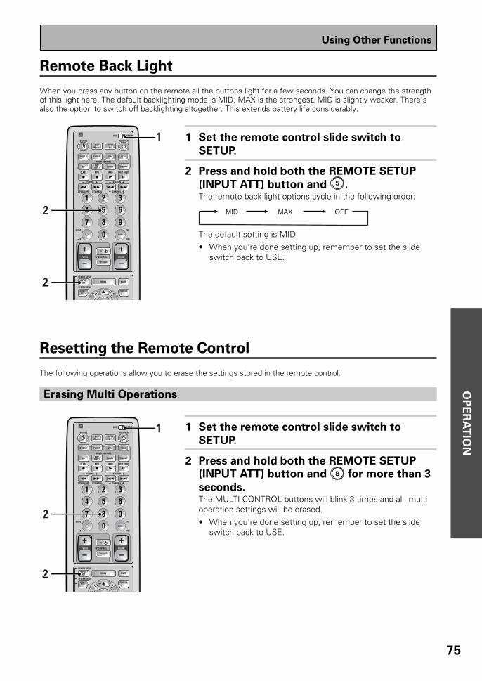
OP
ER
AT
ION
75
Remote Back Light
When you press any button on the remote all the buttons light for a few seconds. You can change the strengthof this light here. The default backlighting mode is MID, MAX is the strongest. MID is slightly weaker. There'salso the option to switch off backlighting altogether. This extends battery life considerably.
1 Set the remote control slide switch to
SETUP.
2 Press and hold both the REMOTE SETUP
(INPUT ATT) button and 5 .The remote back light options cycle in the following order:
MID MAX OFF
The default setting is MID.
• When you're done setting up, remember to set the slideswitch back to USE.
Resetting the Remote Control
The following operations allow you to erase the settings stored in the remote control.
Erasing Multi Operations
1 Set the remote control slide switch to
SETUP.
2 Press and hold both the REMOTE SETUP
(INPUT ATT) button and 8 for more than 3
seconds.The MULTI CONTROL buttons will blink 3 times and all multioperation settings will be erased.
• When you're done setting up, remember to set the slideswitch back to USE.
S0URCE
DVD/LD TV/SAT VCR1 VCR2
CD
TV VOL
TV FUNC
MENU MUTE
TV
VOLUME
MD/TAPE1 TUNER TVCONT
RECEIVER
USE SETUP
MULTIOPERATION
CLASS MPX DIRECT ACCESS
CHANNEL
STATION
TV CONTROL
FUNCTION
REMOTE SETUP
SYSTEM SETUP
INPUTATT
EFFECT/CH SEL
BAND
SYSTEMOFF
1 2 3
4 5 6
7 8 9
0
Î
¶ 87 3
1 ¡ 4 ¢ +-
+-
+-
MULTI CONTROL
+ +
– –
+
1
2
2
DISC
EXIT
+10
GUIDE
ENTER
DTV ON/OFF DTV MENU
TUNING
S0URCE
DVD/LD TV/SAT VCR1 VCR2
CD
TV VOL
TV FUNC
MENU MUTE
TV
VOLUME
MD/TAPE1 TUNER TVCONT
RECEIVER
USE SETUP
MULTIOPERATION
CLASS MPX DIRECT ACCESS
CHANNEL
STATION
TV CONTROL
FUNCTION
REMOTE SETUP
SYSTEM SETUP
INPUTATT
EFFECT/CH SEL
BAND
SYSTEMOFF
1 2 3
4 5 6
7 8 9
0
Î
¶ 87 3
1 ¡ 4 ¢ +-
+-
+-
MULTI CONTROL
+ +
– –
+
1
2
2DISC
EXIT
+10
GUIDE
ENTER
DTV ON/OFF DTV MENU
TUNING
Using Other Functions

76
Erasing Learned Remote Control Commands
Erasing All Learned Commands and Preset Codes
1 Set the remote control slide switch to
SETUP.
2 Press and hold both the REMOTE SETUP
(INPUT ATT) button and 0 for more than 3
seconds.The MULTI CONTROL buttons, SYSTEM OFF button, andMULTI OPERATION button will blink 3 times and allpreset and learned codes will be erased.
• When you're done setting up, remember to set the slideswitch back to USE.
1 Set the remote control slide switch to
SETUP.
2 Press and hold both the REMOTE SETUP
(INPUT ATT) button and 9 for more than 3
seconds.The MULTI CONTROL buttons will blink 3 times and allsignals which have been learned from other remote
controls will be erased.
• When you're done setting up, remember to set the slideswitch back to USE.
S0URCE
DVD/LD TV/SAT VCR1 VCR2
CD
TV VOL
TV FUNC
MENU
ENTER
MUTE
TV
VOLUME
MD/TAPE1 TUNER TVCONT
RECEIVER
USE SETUP
MULTIOPERATION
CLASS MPX DIRECT ACCESS
CHANNEL
STATION
TV CONTROL
FUNCTION
REMOTE SETUP
SYSTEM SETUP
INPUTATT
EFFECT/CH SEL
BAND
SYSTEMOFF
1 2 3
4 5 6
7 8 9
0
Î
¶ 87 3
1 ¡ 4 ¢ +-
+-
+-
MULTI CONTROL
+ +
– –
+
1
2
2DISC
EXIT
+10
GUIDE
ENTER
DTV ON/OFF DTV MENU
TUNING
S0URCE
DVD/LD TV/SAT VCR1 VCR2
CD
TV VOL
TV FUNC
MENU MUTE
TV
VOLUME
MD/TAPE1 TUNER TVCONT
RECEIVER
USE SETUP
MULTIOPERATION
CLASS MPX DIRECT ACCESS
CHANNEL
STATION
TV CONTROL
FUNCTION
REMOTE SETUP
SYSTEM SETUP
INPUTATT
EFFECT/CH SEL
BAND
SYSTEMOFF
1 2 3
4 5 6
7 8 9
0
Î
¶ 87 3
1 ¡ 4 ¢ +-
+-
+-
MULTI CONTROL
+ +
– –
+
1
2
2DISC
EXIT
+10
GUIDE
ENTER
DTV ON/OFF DTV MENU
TUNING
Using Other Functions

OP
ER
AT
ION
77
Video Select
Press the VIDEO SELECT button on the front
panel to cycle through the different possible
video inputs.The first press shows the video input you are currently using.After that pressing VIDEO SELECT cycles though the possibili-ties in the following order:
The OFF setting means the AUDIO and VIDEO source are thesame. (Also, if one of the MD/TAPE 1, CD, TUNER, or PHONOfunctions are selected the VIDEO SELECT will be set to OFF.)
After choosing a video input the display on the receiver willshow that input for about 5 seconds and then revert to showingthe sound mode the receiver is in.
The VIDEO SELECT remains set to the input
you chose until you change the audio input.If you change audio functions the receiver will reset itself tomake the video and audio inputs correspond.
Also, if you switch the power of the receiver OFF when youturn it back on the video and audio inputs will reset so that theycorrespond.
This function allows you to listen to one sound source while you watch a different video source on your TV. Thesound source is set in the normal fashion as is explained on p.45. You then alter the video input with the VIDEOSELECT button.
DVD/LD VCR1 VCR2
OFF VIDEOTV/SAT ( )
STANDBY/ON DSPMODE
MULTI-ROOM&SOURCE
INPUTSELECTOR
MASTERVOLUME
MIN MAX
THX CINEMA ADVANCED STANDARD CONTROL
STANDBY
AUDIO/VIDEO MULTI-CHANNEL RECEIVER
STEREO/DIRECT
/DTS
N∫m¿≤≥ım
PHONES S-VIDEO VIDEO
MULTI CH INPUT
SIGNALSELECT
FLDIMMER
TAPE 2MONITOR
TONECHANNEL
SELECT LOUDNESSDIGITAL
NR CLASS BAND
TUNER CONTROLMEMORYMPX
VIDEOSELCTSPEAKERS
- TUNING +
- STATION +- TREBLE +- BASS +
L AUDIO RVIDEO INPUT
VIDEO VCR 1/DVR VCR 2 DVD/LD TV/SATMD/TAPE1/
CD-R TUNERCD PHONO
VIDEO SELECT
Using Other Functions
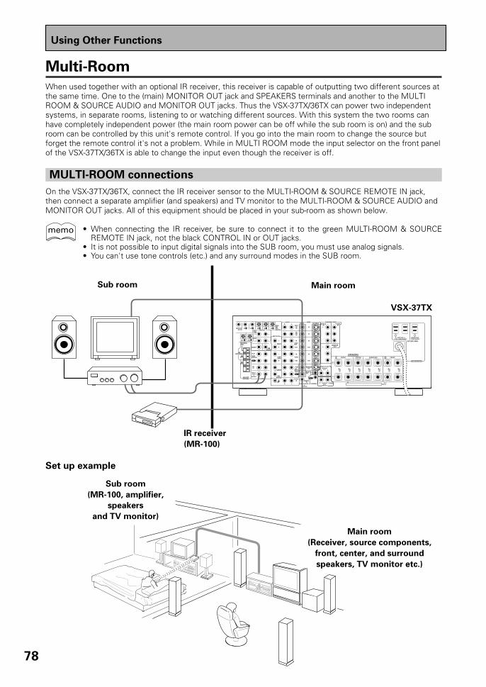
78
Using Other Functions
Multi-Room
When used together with an optional IR receiver, this receiver is capable of outputting two different sources atthe same time. One to the (main) MONITOR OUT jack and SPEAKERS terminals and another to the MULTIROOM & SOURCE AUDIO and MONITOR OUT jacks. Thus the VSX-37TX/36TX can power two independentsystems, in separate rooms, listening to or watching different sources. With this system the two rooms canhave completely independent power (the main room power can be off while the sub room is on) and the subroom can be controlled by this unit's remote control. If you go into the main room to change the source butforget the remote control it's not a problem. While in MULTI ROOM mode the input selector on the front panelof the VSX-37TX/36TX is able to change the input even though the receiver is off.
MULTI-ROOM connections
On the VSX-37TX/36TX, connect the IR receiver sensor to the MULTI-ROOM & SOURCE REMOTE IN jack,then connect a separate amplifier (and speakers) and TV monitor to the MULTI-ROOM & SOURCE AUDIO andMONITOR OUT jacks. All of this equipment should be placed in your sub-room as shown below.
• When connecting the IR receiver, be sure to connect it to the green MULTI-ROOM & SOURCEREMOTE IN jack, not the black CONTROL IN or OUT jacks.
• It is not possible to input digital signals into the SUB room, you must use analog signals.• You can't use tone controls (etc.) and any surround modes in the SUB room.
Main roomSub room
IR receiver
(MR-100)
MONITOROUT
REMOTE IN
CDIN
SURR-OUND
SUBWOOFER
CENTER
FRONT
MULTI CH IN
SURR-OUND
R
R
L
L
R
R
L L
R
L
R L
FRONT
SUBWOOFER
PRE OUT
CENTER
MULTI-ROOM&
SOURCE
DVD /LDIN
S2 VIDEOVIDEOVIDEOAUDIO
IN
TV /SATIN
IN
OUT
IN
VCR1 /DVR
OUT
IN
OUT
IN
VCR2
OUT
IN
MONITOROUT
CONTROL
IN
OUT
MD /TAPE1/CD-R
PLAY
REC
TAPE2MONITOR
PLAY
REC
IN 5IN 4IN 32 RF IN(AC-3)
IN 2IN 1
INPHONO
FM UNBAL75‰
FMANTENNA
AM LOOPANTENNA
MULTI-ROOM
&SOURCE
AUDIO
OUTOUT 21
SPEAKERS
COMPONENT VIDEODVD/LD
INTV/SAT
INY
MONITOROUTY
MULTI CH INSURROUND
BACK
PRE OUT
A FRONT CENTER SURROUND FRONTB
SWITCHEDTOTAL 100W(0.8A)MAX
UNSWITCHED100W(0.8A)MAX
AC120V 60Hz
AC OUTLETS
SURROUNDBACK
R
R L
L (Single)R L
PCM/2/DTSDIGITAL
Set up example
Main room
(Receiver, source components,
front, center, and surround
speakers, TV monitor etc.)
Sub room
(MR-100, amplifier,
speakers
and TV monitor)
memo
VSX-37TX

OP
ER
AT
ION
79
Using Other Functions
MULTI-ROOM set up
After you have completed the necessary connections for MULTI-ROOM operation you need to set up thereceiver for such operation. Follow the instructions below. The page after this one explains how to use theMULTI-ROOM function once it's been set up.
1 Set the slide switch to SETUP.Also make sure that the TV is on and set to the receiver.
2 Press SYSTEM SETUP on the remote
control.The REMOTE SETUP MENU appears on your TV screen. Youcan escape from this screen at any time by pressing SYSTEMSETUP again.
Multi-Room
Volume Level [VARIABLE]IR Receiver [PIONEER][EXIT]
CAUTION : If the "FIXED"position is chosen, the volume will be loud.
3 Use the 5¥∞ buttons to select the MULTI-
ROOM set up mode and press ENTER.
4 Select the VOLUME LEVEL by using the
2¥3 buttons.If you hook up a just a power amplifier in the sub room thereceiver will act as a pre-amp. In this case choose VARIABLEfor the VOLUME LEVEL setting. If you hook up a full integratedamplifier in the sub room (such as another Pioneer VSX receiv-er) choose FIXED for the VOLUME LEVEL setting.
5 Select the IR RECEIVER type with the 5¥∞buttons and select the type by using the
2¥3 buttons.If you have the Pioneer-made MR-100 select PIONEER. If youhave an IR RECEIVER from a different company, selectOTHERS.
6 Move to the EXIT setting and press ENTER
to exit MULTI-ROOM set up and return to
the SYSTEM SETUP MENU operations.You can leave the MULTI ROOM set up mode any time bypressing the SYSTEM SETUP button.
• When you're done setting up, remember to set the slideswitch back to USE.
memo
Some IR RECEIVERS may not workwith this system, check with a Pioneerrepresentative to be sure.
CAUTION!If the MULTI ROOM is set to FIXEDthe volume on the main unit will beset to maximum. Thus, when output,it will be extremely loud. Please setthe master volume controls of the in-tegrated amplifier in the sub roomvery low at first and experiment to finda suitable volume.
AV PRE-PROGRAMMED AND LEARNINGREMOTE CONTROL UNIT
S0URCE
DVD/LD TV/SAT VCR1 VCR2
CD
TV VOL
TV FUNC
MENU
ENTER
STEREO/DIRECTDSP
THXLIGHT
MUTE
TV
VOLUME
MD/TAPE1 TUNER TVCONT
RECEIVER
USE SETUP
MULTIOPERATION
CLASS MPX DIRECT ACCESS
CHANNEL
STATION
TV CONTROL
FUNCTION
REMOTE SETUP
SYSTEM SETUP
INPUTATT
MIDNIGHT MULTI CHINPUT
STANDARD
DIGITALNR
EFFECT/CH SEL
SIGNALSELECT
BAND
SYSTEMOFF
1 2 3
4 5 6
7 8 9
0
Î
¶ 87 3
1 ¡ 4 ¢ +-
+-
+-
MULTI CONTROL
+ +
– –
+
–
2,6 3,45,6
1
ADVANCED
DISC
EXIT
+10
GUIDE
ENTER
/DTS
DTV ON/OFF DTV MENU
TUNING

80
Using the front panel with the MULTI-ROOM system
1 Press the MULTI-ROOM & SOURCE
button.The display shown below will illuminate when thereceiver is in STANDBY mode.Also, the MR&S button will light.
2 Press the CONTROL button.The light will start to blink.
3 Within ten seconds of step 2, select
the FUNCTION with the INPUT
SELECTOR.For this example we'll use the TUNER function. Thedisplay shown below will illuminate.
The INPUT SELECTOR steps through the functions inthe following order:
4 Press the CONTROL button again and
use the INPUT SELECTOR to adjust
the VOLUME. The volume can be
adjusted in a range of -82dB to 0dB.The display will appear as shown below.
5 When in TUNER function, press the
CONTROL button and use the INPUT
SELECTOR to tune in the station.The display will appear as shown below.
Turn the input selector until you get:
TUNER MD/TAPE 1VCR 1
TV/SATDVD/LD CD
MULTI-ROOM&SOURCE
INPUTSELECTOR
MASTERVOLUME
MIN MAX
OL
TUNING +
STATION +
ONO
CONTROL
1
2,4,5 3,4,5
MULTI-ROOM&SOURCE
CONTROL
«
Using Other Functions
«
If you don't turn the multi roomfunction off you won't be able to turnthe entire main room system off.
memo

OP
ER
AT
ION
81
Using the remote control with the MULTI-ROOM system
Using Other Functions
SUB room MAIN room
MULTI-ROOM& SOURCE
CONTROL
REFERENCE AUDIO/VIDEO MULTI—CHANNEL RECEIVER
1 Set the slide switch to USE.
2 From the sub room, point the remote
control at the MULTI ROOM sensor and
press the RECEIVER button.The MULTI ROOM & SOURCE button will light on the frontpanel in the main room.
3 Press a FUNCTION button to select the sub
function.You can also use the MULTI OPRATION buttons to select thefeature.
4 Press VOLUME +/– to adjust the volume.The following remote control buttons can be used to operatethe receiver from the sub room.
• RECEIVER button• FUNCTION button (will not select PHONO, VCR 2 or VIDEO)
• VOLUME +/– buttons (for adjusting the sub-room's volumelevel, but can't be used when set to FIXED)
• CLASS button (for selecting the desired class)• STATION –/+ button (for recalling memorized radio stations
(the tuner is selected automatically))
• Number button (0-9)
AV PRE-PROGRAMMED AND LEARNINGREMOTE CONTROL UNIT
S0URCE
DVD/LD TV/SAT VCR1 VCR2
CD
TV VOL
TV FUNC
MENU
ENTER
STEREO/DIRECTDSP
THXLIGHT
MUTE
TV
VOLUME
MD/TAPE1 TUNER TVCONT
RECEIVER
USE SETUP
MULTIOPERATION
CLASS MPX DIRECT ACCESS
CHANNEL
STATION
TV CONTROL
FUNCTION
REMOTE SETUP
SYSTEM SETUP
INPUTATT
MIDNIGHT MULTI CHINPUT
STANDARD
DIGITALNR
EFFECT/CH SEL
SIGNALSELECT
BAND
SYSTEMOFF
1 2 3
4 5 6
7 8 9
0
Î
¶ 87 3
1 ¡ 4 ¢ +-
+-
+-
MULTI CONTROL
+ +
– –
+
–
4
3
1
3
ADVANCED
DISC
EXIT
+10
GUIDE
ENTER
/DTS
2
DTV ON/OFF DTV MENU
TUNING

82
Using Other Functions
• You can also control PIONEER components (and those made by other manufacturers) by pointing thereceiver's remote control directly at the respective component. This type of operation does not re-quire control cords. All you have to do is recall the appropriate the stored settings (see p.58-59).
• If you use a remote control hooked up via the CONTROL IN jack with a control cord, you won't be ableto use this unit's remote control.
• Remote operation may not be possible if direct light from a strong fluorescent lamp is shining on theIR receiver remote sensor window.
• The tuner cannot be tuned to more than one station at a time. Therefore, changing the station in oneroom also changes the station in the other room. Please be careful not to change stations whenrecording a radio broadcast.
• The volume levels of the main and sub rooms are independent.• When more than one remote control signal is transmitted at the same time, the receiver does not
operate.• When operating MULTI-ROOM & SOURCE with the MULTI-ROOM PRE OUT jacks connected to a
SUB room amplifier which bears the PIONEER Î mark and has a remote sensor, both the IR receiverand the amplifier may receive remote control commands (making correct operation impossible). Inthis case, place the IR receiver and amplifier apart from each other, and point the remote controldirectly at the IR receiver during operation.
• If you plan to leave the MULTI ROOM feature off for a lengthy period please turn off the power in boththe SUB and MAIN rooms. Make sure the STANDBY indicator turns red and the MR&S indicator goesoff.
• If you send the SYSTEM OFF command from the SUB room by remote control, the power of bothrooms will go off. Please be careful when making a recording in the MAIN room.
The PIONEER SR System: Operating other PIONEER components
Connecting an optional control cord allows you to operate other PIONEER components simply by pointing thereceiver's remote control at the remote sensor on the front panel of the receiver. The receiver then sends theremote control signals to the other devices via the CONTROL OUT terminal.
memo
memo
OUT
IN
CONTROL
OUT
IN
CONTROL
PIONEER component bearing the Î mark.
Remote Control
To CONTROL IN terminal of another PIONEER component bearing the Î mark.
Receiver
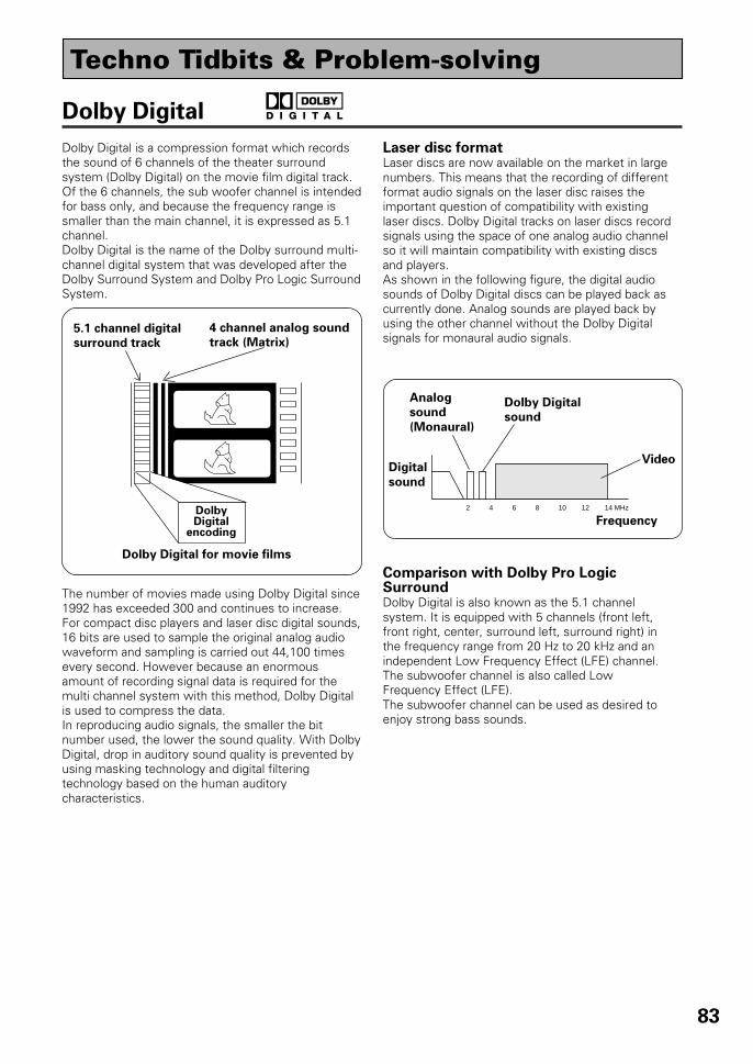
83
Dolby Digital
Digital
sound
2 4 6 8 10 12 14 MHz
Frequency
Analog
sound
(Monaural)
Video
Dolby Digital
sound
Dolby Digital is a compression format which recordsthe sound of 6 channels of the theater surroundsystem (Dolby Digital) on the movie film digital track.Of the 6 channels, the sub woofer channel is intendedfor bass only, and because the frequency range issmaller than the main channel, it is expressed as 5.1channel.Dolby Digital is the name of the Dolby surround multi-channel digital system that was developed after theDolby Surround System and Dolby Pro Logic SurroundSystem.
The number of movies made using Dolby Digital since1992 has exceeded 300 and continues to increase.For compact disc players and laser disc digital sounds,16 bits are used to sample the original analog audiowaveform and sampling is carried out 44,100 timesevery second. However because an enormousamount of recording signal data is required for themulti channel system with this method, Dolby Digitalis used to compress the data.In reproducing audio signals, the smaller the bitnumber used, the lower the sound quality. With DolbyDigital, drop in auditory sound quality is prevented byusing masking technology and digital filteringtechnology based on the human auditorycharacteristics.
Laser disc formatLaser discs are now available on the market in largenumbers. This means that the recording of differentformat audio signals on the laser disc raises theimportant question of compatibility with existinglaser discs. Dolby Digital tracks on laser discs recordsignals using the space of one analog audio channelso it will maintain compatibility with existing discsand players.As shown in the following figure, the digital audiosounds of Dolby Digital discs can be played back ascurrently done. Analog sounds are played back byusing the other channel without the Dolby Digitalsignals for monaural audio signals.
Comparison with Dolby Pro LogicSurroundDolby Digital is also known as the 5.1 channelsystem. It is equipped with 5 channels (front left,front right, center, surround left, surround right) inthe frequency range from 20 Hz to 20 kHz and anindependent Low Frequency Effect (LFE) channel.The subwoofer channel is also called LowFrequency Effect (LFE).The subwoofer channel can be used as desired toenjoy strong bass sounds.
5.1 channel digital
surround track
4 channel analog sound
track (Matrix)
DolbyDigital
encoding
Dolby Digital for movie films
Techno Tidbits & Problem-solving
1
84
THX
DTS
DTS has been adopted as a sound recording format in the latest movie theaters since the release of “JURASSICPARK” in 1993, and has a good reputation for high quality sound and dynamic surround effects.In this system, 6 channels of digital sound are recorded on CD-ROM, rather than on the film. DTS adopts asimultaneous playback format. With a low rate of compression of sound signals and a high rate of transmittance,a higher sound quality format is produced. Also, unlike the process of recording digital sounds on film directly,the only components required are a CD-ROM player as might be used with a personal computer and a DTSprocessor, and therefore less investment is required than with other formats. For this reason, the format isbeing introduced in more and more movie theaters, and is being adopted in home movie software (DVD, LD)and music software (5.1 channel CD). DTS has recently added a third surround channel to its system. This hascome to be known as DTS Extended Surround or simply DTS-ES.
Techno Tidbits & Problem-solving
THX is a Lucasfilm, Ltd. program dedicated to maximum accuracy in movie presentation. Movie sound tracksare recorded in large movie dubbing stages using movie theater equipment. For a sound track to be presentedaccurately in your home, special technologies are required. In your home the room is much smaller and has abright sound, the speakers are very different and there are only six-eight of them, plus, you sit much closer toeach one of those speakers. Because of these differences we often miss the power and emotion that thrillsus in a good movie. Now Pioneer and THX have teamed up to bring the full glory of accurate cinema sound tothe comfort and convenience of your home.
Re-Equalization™ : In a theater the room is very large and dead sounding, you sit a long way back from thespeakers and the speakers themselves are very specialized. Because a sound track recorded in this deadsounding space when it is played at home it sounds overbright. THX Re-Equalization adjusts for this differencein a very precise way.
Adaptive Decorrelation™ : When a sound track sends mono sound to the surround speakers it often seemsto be coming come from one side instead of from all around you as it would in a theater. AdaptiveDecorrelation helps to correct this inaccuracy.
Timbre Matching™ : When recording a sound track it is very important that the surround sounds movesmoothly and seamlessly around the theater. It is very distracting when sounds seem to jump from speaker tospeaker. Timbre Matching helps to smooth the movement of the surround sounds even though you are usingonly two speakers.
Bass Peak Level Manager™ : Some Dolby Digital sound tracks can produce bass peaks that are undesirablein a home theater environment. The Bass Peak Level Manager allows you to set the maximum peak levelsappropriate to your system. (Set this function according to the Bass Peak Level instructions on page 38.)
Loudspeaker Position Time Synchronization™ : This feature allows you to adjust for the difference in thedistance from each individual loudspeaker to the listening position. Doing this ensures that all the speakersoperate in precise synchronization improving the seamless nature of the soundfield. (Set this functionaccording to the Channel Delay instructions on p.34.)
THX Surround EX™ : THX Surround EX–Dolby Digital Surround EX is a joint development of DolbyLaboratories and the THX division of Lucasfilm Ltd.
In a movie theater, film soundtracks that have been encoded with Dolby Digital Surround EX technology areable to reproduce an extra channel which has been added during the mixing of the program. This channel,called Surround Back, places sounds behind the listener in addition to the currently available front left, frontcenter, front right, surround right, surround left and subwoofer channels. This additional channel provides theopportunity for more detailed imaging behind the listener and brings more depth, spacious ambience andsound localization than ever before.
Movies that were created using the Dolby Digital Surround EX technology, when released into the homeconsumer market may exhibit a Dolby Digital Surround EX logo on the packaging. A list of movies createdusing this technology can be found on the Dolby web site at http://www.dolby.com.
Only receiver and controller products bearing the THX Surround EX logo, when in the THX Surround EX mode,faithfully reproduce this new technology in the home.
This product may also engage the "THX Surround EX" mode during the playback of 5.1 channel material that isnot Dolby Digital Surround EX encoded. In such case the information delivered to the Surround Back channelwill be program dependent and may or may not be very pleasing depending on the particular soundtrack andthe tastes of the individual listener.
R

85
Techno Tidbits & Problem-solving
Preset Code List
Manufacturer
TOSHIBASONYPANASONICJVCSAMSUNGSHARPAKAIRCAPIONEER
SONYPANASONICKENWOODPHILIPSMITSUBISHIRCAPIONEER
RCASONYECHOSTARPIONEER
ORIONFUNAIRCA
ZENITHMAGNAVOXFISHER
PANASONICTOSHIBAJVC
HITACHISONY
MITSUBISHI
SANYOSHARPGOLDSTAROPTIMUS
GRANDIENTEPIONEER
MARANTZSONYTECHNICSKENWOODTEACDENONONKYOYAMAHAJVCFISHEROPTIMUSPIONEER
Device
DVD
LD
STB
VCR
TAPE
Manufacturer
SONYTECHNICSKENWOODDENONRCAPHILIPSYAMAHAJVCTEACONKYOMARANTZSANYOOPTIMUSPIONEER
SONYKENWOODSHARPTEACONKYODENONPIONEER
RCA
ZENITHMAGNAVOXGE
PANASONICSONYTOSHIBAMITSUBISHIHITACHIJVCSHARPSANYOPHILIPSGOLDSTARRADIO SHACKGRANDIENTEFUNAIPIONEER
JERROLD
S.ATLANTAZENITHPIONEER
PIONEER
Code
001002003004005006007009000, 008
101105, 106103104100107100, 111
201(SAT), 203(SAT)202(SAT)205(SAT)200(SAT), 207(DTV)
445, 446, 424441401, 406, 408, 414, 405, 413,411, 415403, 404, 417414, 408, 426, 403410, 426, 412, 427, 425,420408, 432, 433405, 409, 426428, 430, 429, 408, 414,431, 407408, 401, 406, 436, 434416, 417, 404, 408, 457,458, 459409, 420, 421, 422, 423,424, 408, 407410, 412, 425, 435402, 418, 419411, 409408, 432, 433, 402, 418,419441400, 456(DVR)
821801, 806803804, 807805810809, 808811, 812802813800800
Device
CD
MD
TV
CATV
TUNER
Code
301, 316, 317, 318304, 326310, 321, 311309302, 319, 313312, 322, 346(CD-R)315, 314, 328303305, 306, 327, 324, 325320, 308, 307323, 312, 324313300300, 345(CD-R)
901903902904905906900, 902, 907(DAT)
601, 610, 615, 616, 617,618603, 620607, 610, 603, 612, 629601, 608, 607, 610, 617,602, 628618608, 622, 607604605, 602, 626, 621609, 610, 602, 621606, 610, 624, 625, 618613, 623602, 619, 627621, 614607610, 623, 621, 602610, 623, 621, 602
630658600
219, 209, 210, 220, 212,221, 211, 222, 224, 223213, 214, 216, 217215, 225, 218208
500

86
TroubleshootingIncorrect operations are often mistaken for trouble and malfunctions. If you think that there is something wrong withthis component, check the points below. Sometimes the trouble may lie in another component. Investigate the othercomponents and electrical appliances being used. If the trouble cannot be rectified even after exercising the checkslisted below, ask your nearest PIONEER authorized service center or your dealer to carry out repair work.
Cause
• The power plug is disconnected.
• The protection circuit may havebeen activated.
• Static electricity caused by dry air.
• Improper connections.
• Sound is muted.• The volume is turned down.• The TAPE 2 MONITOR is ON.• Speakers are turned OFF.
• DIGITAL/ANALOG switch is setincorrectly.
• Improper connections.
• The input source is not properlyselected.
• Incorrect frequency.• The antenna is not connected.• 2 RF and/or digital cables are near
the antenna terminals and wires.FM broadcasts• The FM antenna is not fully
extended or is poorly positioned.
• Weak radio signals.
AM broadcasts• The AM antenna is poorly
positioned.• Weak radio signals.
• Interference caused by otherequipment (fluorescent lamp,motor, etc.).
• Weak radio signals.
• Settings route signal away fromsubwoofer.
• The LD is not a Dolby Digitalcompatible disc.
• The Dolby Digital / DTS source isnot 5 channels.
Symptom
The power does not turn ON.
The unit does not respond whenthe buttons are pressed.
No sound is output when afunction is selected.
No image is output when afunction is selected.
Considerable noise in radiobroadcasts.
Broadcast stations cannot beselected automatically.
Subwoofer output is very low.
When playing an LD the SIGNALSELECT is on 2 RF but there isstill no sound.
When playing a Dolby Digital / DTSsource the 5.1 Channel indicatordoesn't light.
Remedy
• Connect the power plug to the walloutlet.
• Disconnect the power plug from theoutlet, and insert again.
• Disconnect the power plug from theoutlet, and insert again.
• Make sure the component isconnected correctly (see p. 12-21).
• Press MUTE on the remote control.• Adjust MASTER VOLUME.• Press the TAPE 2 MONITOR button.• Press SPEAKERS (A/B) to select the
speakers you connected.• Set SIGNAL SELECT (see p. 47).
• Make sure the component isconnected correctly (see p.15-18).
• Press the correct function button.
• Tune in the correct frequency.• Connect the antenna (see p.18).• Route 2 RF and digital cables away
from the antenna terminals and wires.
• Fully extend the FM wire antenna,position for best reception, andsecure to a wall.
• Connect an outdoor FM antenna (seep.18).
• Adjust the direction and position forbest reception.
• Connect an additional internal orexternal AM antenna (see p.18).
• Turn off the equipment causing thenoise or move it away from thereceiver.
• Place the antenna farther away fromthe equipment causing the noise.
• Connect an outdoor antenna (seep.18).
• To get more signal to the subwooferset it to PLUS or choose SMALL forthe FRONT speakers (see p.32-33).
• Set the SIGNAL SELECT to analog(make sure your LD player is hookedup with analog connections in additionto digital and 2 RF connections, seep. 15).
• There is no problem with the receiverbut if you want 5 channel sound youmust play a 5 channel source.
Techno Tidbits & Problem-solving

87
Techno Tidbits & Problem-solving
Cause
• Speaker settings are incorrect.
• The rear and/or center levels areturned down.
• The surround and/or centerspeakers are disconnected.
• SIGNAL SELECT is set incorrectly.
• The digital inputs are assignedincorrectly, or not at all.
• SIGNAL SELECT is set to“ANALOG”.
• A DVD player not compatible withDTS is used, or the setting of theDVD player is incorrect.
• The digital output level has beenturned down on a CD player orother component equipped withdigital output level adjustmentcapability. (The DTS signal has beenaltered by the player, and cannot beread.)
• The speakers are tunred OFF.
• Disc being played back has a hugeamount of information on it.
• The search function performed bythe player interferes with thereading of digital information.
• The remote control batteries haveworn out.
• Too far away or bad angle ofoperation.
• There is an obstacle between thereceiver and the remote control.
• Strong light such as fluorescentlight is shining onto the unit'sremote control signal light-receivingwindow.
• A cord is connected to theCONTROL IN terminal on this unit.
• The IR -Receiver type ismismatched with the setting.
•The FL DIMMER button is pushed.
• If you are using an analog source,the signal is too strong.
• If you are using a digital source,there is too much information forthe receiver to handle.
• The SIGNAL SELECT is onANALOG.
Remedy
• See “SPEAKER SETTING” on p.32-33to check the speaker settings.
• See “CHANNEL LEVEL” p.35-36 tocheck the speaker levels.
• Connect the speakers (see p.19).
• Set SIGNAL SELECT to “AUTO” oraccording to the type of connectionsmade (see p. 47).
• Set the digital input settings correctly(see p.31).
• Make digital connections (see p.13)and set SIGNAL SELECT to “AUTO”(see p.47).
• Refer to the instruction manualsupplied with the DVD player.
• Set the digital volume level of theplayer to full, or to the neutralposition.
• Turn the speakers ON.
• Use the STANDARD mode to getthe best results (see p.44).
• This is not a malfunction, but be sureto turn the volume down to preventthe output of loud noise from yourspeakers.
• Replace the batteries (see p.10).
• Operate within 7 m, 30° of the remotesensor on the front panel (see p.11).
• Remove the obstacle or operate fromanother position.
• Avoid exposing the remote sensor onthe front panel to direct light.
• Connect cord to the correct jack.
• Disconnect the IR Receiver from therear panel, and set to the other IRReceiver type using the remotecontrol.
• Press FL DIMMER on the front panelrepeatedly to return to the defaultsetting (see p.52).
• Press the INPUT ATT button (seep.27).
• For 2/DTS sources put the receiverin STANDARD mode (see p.44).
• Set the SIGNAL SELECT to DIGITAL.
Symptom
No sound from surround orcenter speakers.
Sound is produced from somecomponents, but not fromdigital components.
No sound is output or a noise isoutput when software with DTSis played back.
The sound is outputintermittently when softwarewith DTS is played back.
When a search is performed bya DTS compatible CD playerduring playback, noise is output.
Cannot be remote controlled.
The display is dark.
The OVER indicator isconstantly lit.
When playing a Dolby Digital /DTS format LD there is noiseaudible on the soundtrack.

88
Cause
• Either the digital connections or theDIGITAL IN SELECT choices areincorrect.
• The TAPE2 MONITOR mode is ON.
• You are not using a source withSurround EX flag.
• The player is paused or stopped.• There is a mistake in the player
settings for audio output.
• Although it's a Dolby Digital / DTSsource there is a possibility thepresent track is not Dolby Digital /DTS.
Remedy
• Make sure the digital connections andthe DIGITAL IN SELECT choices aredone correctly.
• Press the TAPE2 MONITOR button soit goes into the OFF setting.
• There is no problem with yourreceiver but if you want to hear 7channel sound use an Surround EXsource.
• Play the source.• Fix the audio settings (check the
manual that came with your DVDplayer.
• There is no problem. The indicatorwon't light when the track is not aDolby Digital / DTS track.
Symptom
You can't get DIGITAL to comeup when using the SIGNALSELECT button.
When using THX AUTO modethe receiver is not playing in theEX mode.
The Dolby Digital / DTSindicator doesn't light up evenwhen playing a Dolby Digital /DTS source.
If the unit does not operate normally due to external effects such as static electricityDisconnect the power plug from the outlet and insert again to return to normal operating conditions.
Techno Tidbits & Problem-solving

89
Techno Tidbits & Problem-solving
Selecting fine audio equipment such as the unit you’vejust purchased is only the start of your musical enjoyment.Now it’s time to consider how you can maximize the funand excitement your equipment offers. This manufacturerand the Electronic Industries Association’s ConsumerElectronics Group want you to get the most out of yourequipment by playing it at a safe level. One that lets thesound come through loud and clear without annoyingblaring or distortion-and, most importantly, withoutaffecting your sensitive hearing.
Sound can be deceiving. Over time your hearing“comfort level” adapts to higher volumes of sound. Sowhat sounds “normal” can actually be loud and harmfulto your hearing. Guard against this by setting yourequipment at a safe level BEFORE your hearing adapts.
To establish a safe level:• Start your volume control at a low setting.• Slowly increase the sound until you can hear it
comfortably and clearly, and without distortion.
Once you have established a comfortable sound level:• Set the dial and leave it there.
Taking a minute to do this now will help to preventhearing damage or loss in the future. After all, we wantyou listening for a lifetime.
EST 1924
EIAEL
EC
TR
ONIC INDU
ST
RIE
S
•A
SS O C I A T I O
N•
WeWant You
LISTENINGFor A Lifetime
We Want You Listening For ALifetime
Used wisely, your new sound equipment will provide alifetime of fun and enjoyment. Since hearing damage fromloud noise is often undetectable until it is too late, thismanufacturer and the Electronic Industries Association’sConsumer Electronics Group recommend you avoidprolonged exposure to excessive noise. This list of soundlevels is included for your protection.
DecibelLevel Example
30 Quiet library, soft whispers40 Living room, refrigerator, bedroom away from
traffic50 Light traffic, normal conversation, quiet office60 Air conditioner at 20 feet, sewing machine70 Vacuum cleaner, hair dryer, noisy restaurant80 Average city traffic, garbage disposals, alarm clock
at two feet.
THE FOLLOWING NOISES CAN BEDANGEROUS UNDER CONSTANT EXPOSURE
90 Subway, motorcycle, truck traffic, lawn mower100 Garbage truck, chain saw, pneumatic drill120 Rock band concert in front of speakers, thunderclap140 Gunshot blast, jet plane180 Rocket launching pad
Information courtesy of the Deafness Research Foundation.
EST 1924
EIAEL
EC
TR
ONIC INDU
ST
RIE
S
•A
SS O C I A T I O
N•
WeWant You
LISTENINGFor A Lifetime

90
Specifications
Amplifier Section
VSX-37TX :
Continuous average power output of 120watts* per channel, min., at 6 ohms, from20 Hz to 20,000 Hz with no more than 0.09%** total harmonic distortion (front).
VSX-36TX:
Continuous average power output of 100watts* per channel, min., at 8 ohms, from20 Hz to 20,000 Hz with no more than 0.09%** total harmonic distortion (front).
VSX-37TX :
Continuous Power OutputFront ..... 120 W + 120 W (20 Hz-20 kHz, 0.09 %, 6 Ω)Center ................. 120 W (20 Hz-20 kHz, 0.09 %, 6 Ω)Rear ...... 120 W + 120 W (20 Hz-20 kHz, 0.09 %, 6 Ω)
VSX-36TX :
Continuous Power OutputFront ..... 100 W + 100 W (20 Hz-20 kHz, 0.09 %, 8 Ω)Center ................. 100 W (20 Hz-20 kHz, 0.09 %, 8 Ω)Rear ...... 100 W + 100 W (20 Hz-20 kHz, 0.09 %, 8 Ω)
Audio SectionInput (Sensitivity/Impedance)
PHONO MM .......................................... 4.7 mV/47 kΩVCR 1/DVR, VCR 2, DVD/LD, TV/SAT, VIDEO, CDMD/TAPE 1/CD-R, TAPE 2 ..................... 335 mV/47 kΩ
Phono Overload level (T.H.D.0.1 %, 1kHz)PHONO MM ................................................... 120 mV
Frequency ResponsePHONO MM .................. 20 Hz to 20,000 Hz ± 0.3 dBVCR 1/DVR, VCR 2, DVD/LD, TV/SAT, VIDEO, CDMD/TAPE 1/CD-R, TAPE 2 .... 5 Hz to 100,000 Hz dB
Output (Level/Impedance)VCR 1/DVR REC, VCR 2 REC, MD/TAPE 1/CD-R RECTAPE 2 REC ......................................... 335 mV/2.2 kΩ
Tone ControlBASS ................................................... ± 6 dB (100 Hz)TREBLE ............................................... ± 6 dB (10 kHz)LOUDNESS ............................ +10 dB (100 Hz/10 kHz)
Signal-to-Noise Ratio (IHF, short circuited, A network)PHONO MM ...................................................... 80 dBVCR 1/DVR, VCR 2, DVD/LD, TV/SAT, VIDEO, CDMD/TAPE 1CD-R, TAPE 2 ................................. 101 dBMULTI CHANNEL IN ... 101 dB(Channel Level:Bypass)
Signal-to-Noise Ratio [EIA, at 1 W (1 kHz)]PHONO MM ...................................................... 80 dBVCR 1/DVR, VCR 2, DVD/LD, TV/SAT, VIDEO, CDMD/TAPE 1/CD-R, TAPE 2 .................................. 83 dB
* Measured pursuant to the Federal Trade Commission’sTrade Regulation rule on Power Output Claims forAmplifiers.
** Measured by Audio Spectrum Analyzer.
+0–3
Video SectionInput (Sensitivity) .......................................... 1 Vp-p/75 ΩOutput (Level/Impedance) ............................ 1 Vp-p/75 ΩSignal-to-Noise Ratio .............................................. 65 dBFrequency Response ..................... 5 Hz to 10 MHz dB
Component Video SectionInput (Sensitivity) .......................................... 1 Vp-p/75 ΩOutput (Level/Impedance) ............................ 1 Vp-p/75 ΩSignal-to-Noise Ratio .............................................. 65 dB
FM Tuner SectionFrequency Range ......................... 87.5 MHz to 108 MHzUsable Sensitivity ...... Mono: 13.2 dBf, IHF (1.3 µV/75 Ω)50 dB Quieting Sensitivity ....................... Mono: 20.2 dBf
Stereo: 38.6 dBfSignal-to-Noise Ratio ................. Mono: 73 dB (at 85 dBf)
Stereo: 70 dB (at 85 dBf)Distortion ...................................... Stereo: 0.5 % (1 kHz)Alternate Channel Selectivity ................. 60 dB (400 kHz)Stereo Separation ...................................... 40 dB (1 kHz)Frequency Response ............... 30 Hz to 15 kHz (± 1) dBAntenna Input ....................................... 75 Ω unbalanced
AM Tuner SectionFrequency Range .......................... 530 kHz to 1,700 kHzSensitivity (IHF, Loop antenna) ......................... 350 µV/mSelectivity ............................................................... 25 dBSignal-to-Noise Ratio .............................................. 50 dBAntenna ...................................................... Loop antenna
MiscellaneousPower Requirements ............................. AC 120 V, 60 HzVSX-37TX :
Power Consumption ................................ 460 W, 630 VAPower Consumption in Standby mode .................. 1.0 WAC Outlet
SWITCHED (×2) .................... Total 100 W (0.8 A) MAXUNSWITCHED .............................. 100 W (0.8 A) MAX
Dimensions .................. 420 (W) × 173 (H) × 470 (D) mm(16-9/16 (W) × 6-13/16 (H) × 18-1/2 (D) in.)
Weight (without package) ................. 15.2 kg (33 lb 9 oz)VSX-36TX :
Power Consumption ................................ 400 W, 550 VAPower Consumption in Standby mode .................. 1.0 WAC Outlet
SWITCHED (×2) .................... Total 100 W (0.8 A) MAXUNSWITCHED .............................. 100 W (0.8 A) MAX
Dimensions .................. 420 (W) × 173 (H) × 470 (D) mm(16-9/16 (W) × 6-13/16 (H) × 18-1/2 (D) in.)
Weight (without package) ............... 14.4 kg (31 lb 13 oz)
Techno Tidbits & Problem-solving
+0–3

91
Maintenance of External Surfaces• Use a polishing cloth or dry cloth to wipe off dust
and dirt.• When the surfaces are dirty, wipe with a soft
cloth dipped in some neutral cleanser diluted fiveor six times with water, and wrung out well, andthen wipe again with a dry cloth. Do not usefurniture wax or cleaners.
• Never use thinners, benzine, insecticide spraysor other chemicals on or near this unit, sincethese will corrode the surfaces.
Techno Tidbits & Problem-solving
Power cord CAUTION!Handle the power cord by the plug. Do not pull outthe plug by tugging the cord and never touch thepower cord when your hands are wet as this couldcause a short circuit or electric shock. Do not placethe unit, a piece of furniture, etc., on the power cord,or pinch the cord. Never make a knot in the cord or tieit with other cords. The power cords should be routedsuch that they are not likely to be stepped on. Adamaged power cord can cause a fire or give you anelectrical shock. Check the power cord once in awhile. When you find it damaged, ask your nearestPIONEER authorized service center or your dealer fora replacement.
Furnished PartsFM wire Antenna ........................................................... 1AM loop Antenna ........................................................... 1“AA” IEC LR6 batteries ................................................. 2Remote Control Unit ...................................................... 1Operating Instructions ................................................... 1
NOTE:
Specifications and the design are subject to possiblemodifications without notice, due to improvements.

<ARB7231-A>Printed in Japan<00C00ZF0P00>
Published by Pioneer Corporation.Copyright © 2000 Pioneer Corporation.All rights reserved.
PIONEER CORPORATION 4-1, Meguro 1-Chome, Meguro-ku, Tokyo 153-8654, Japan
PIONEER ELECTRONICS [USA] INC. P.O. BOX 1540, Long Beach, California 90801-1540, U.S.A.PIONEER ELECTRONICS OF CANADA, INC. 300 Allstate Parkway, Markham, Ontario L3R OP2, CanadaPIONEER EUROPE NV Haven 1087, Keetberglaan 1, B-9120 Melsele, Belgium TEL: 03/570.05.11PIONEER ELECTRONICS AUSTRALIA PTY. LTD. 178-184 Boundary Road, Braeside, Victoria 3195, Australia, TEL: [03] 9586-6300PIONEER ELECTRONICS DE MEXICO S.A. DE C.V. San Lorenzo 1009 3er Piso Desp. 302 Col. Del Valle Mexico D.F. C.P. 03100
TEL: 5-688-52-90
Should this product require service in the U.S.A. and you wish to locate the nearest Pioneer
Authorized Independent Service Company, or if you wish to purchase replacement parts,
operating instructions, service manuals, or accessories, please call the number shown below.
8 0 0 – 4 2 1 – 1 4 0 4
Please do not ship your product to Pioneer without first calling the Customer Service
Department at the above listed number for assistance.
PIONEER ELECTRONICS SERVICE, INC.CUSTOMER SERVICE DEPARTMENTP.O. BOX 1760, LONG BEACH,CA 90801-1760, U.S.A.
For warranty information please see the Limited Warranty sheet included with your product.
Si ce produit doit être réparé au Canada, veuillez vous adresser à un distributeur autoriséePioneer au Canada pour obtenir le nom de la Société de Service Autorisée Pioneer le plusprès de chez vous. Ou encore, veuillez vous communiquer avec le Service de Clientèle dePioneer:
Pioneer électroniques du Canada, Inc.Département de service au consommateurs300 Allstate Parkway, Markham, Ontario L3ROP2(905) 479-44111-877-283-5901
Should this product require service in Canada, please contact a Pioneer Canadian AuthorizedDealer to locate the nearest Pioneer Authorized Service Company in Canada.Alternatively, please contact the Customer Service Department at the following address:
Pioneer Electronics of Canada, Inc.Customer Service Department300 Allstate Parkway, Markham, Ontario L3ROP2(905) 479-44111-877-283-5901
Pour obtenir des renseignements sur la garantie, veuillez vous reporter au feuillet sur laGarantie Limitée gui accompagne le produit.
For warranty information please see the Limited Warranty sheet included with your product.