
MULTI CHANNEL AV RECEIVER STR-ZA3100ES/STR-ZA2100ES…
197
MULTI CHANNEL AV RECEIVER STR-ZA3100ES/STR-ZA2100ES/STR- ZA1100ES Parts and Controls Receiver Front panel (with the front cover attached) [1] Front panel (without the front cover attached) [2] Power indicator [3] Indicators on the display panel [4] Rear panel (STR-ZA3100ES) [5] Rear panel (STR-ZA2100ES) [6] Rear panel (STR-ZA1100ES) [7] Remote control Remote control (upper section) [8] Remote control (lower section) [9] Preparation 1. Installing speakers Locations and names of speakers [10] Installing 7.1-channel speaker system [11] Installing 5.1.2-channel speaker system using top middle speakers [12] Installing 5.1.4-channel speaker system using top front and top rear speakers with an additional stereo power amplifier (for STR-ZA3100ES/STR-ZA2100ES) [13] Installing 7.1.2-channel speaker system using front Dolby Atmos enabled speakers with an additional stereo power amplifier (for STR-ZA3100ES/STR-ZA2100ES) [14] Installing 5.1-channel speaker system with Zone 2 connection [15] Installing 5.1.2-channel speaker system with bi-amplifier connection (for STR-ZA3100ES/STR-ZA2100ES) [16] Installing 5.1-channel speaker system with bi-amplifier connection [17] Speaker configuration and speaker pattern settings [18]
Transcript of MULTI CHANNEL AV RECEIVER STR-ZA3100ES/STR-ZA2100ES…

MULTI CHANNEL AV RECEIVER STR-ZA3100ES/STR-ZA2100ES/STR-ZA1100ES
Parts and Controls
Receiver
Front panel (with the front cover attached) [1]
Front panel (without the front cover attached) [2]
Power indicator [3]
Indicators on the display panel [4]
Rear panel (STR-ZA3100ES) [5]
Rear panel (STR-ZA2100ES) [6]
Rear panel (STR-ZA1100ES) [7]
Remote control
Remote control (upper section) [8]
Remote control (lower section) [9]
Preparation
1. Installing speakers
Locations and names of speakers [10]
Installing 7.1-channel speaker system [11]
Installing 5.1.2-channel speaker system using top middle speakers [12]
Installing 5.1.4-channel speaker system using top front and top rear speakers with an additional stereo poweramplifier (for STR-ZA3100ES/STR-ZA2100ES) [13]
Installing 7.1.2-channel speaker system using front Dolby Atmos enabled speakers with an additional stereopower amplifier (for STR-ZA3100ES/STR-ZA2100ES) [14]
Installing 5.1-channel speaker system with Zone 2 connection [15]
Installing 5.1.2-channel speaker system with bi-amplifier connection (for STR-ZA3100ES/STR-ZA2100ES) [16]
Installing 5.1-channel speaker system with bi-amplifier connection [17]
Speaker configuration and speaker pattern settings [18]
2. Connecting speakers
Connecting 7.1-channel speaker system [19]
Connecting 5.1.2-channel speaker system using top middle speakers [20]
Connecting 5.1.4-channel speaker system using top front and top rear speakers with an additional stereopower amplifier (for STR-ZA3100ES/STR-ZA2100ES) [21]
Connecting 7.1.2-channel speaker system using front Dolby Atmos enabled speakers with an additional stereopower amplifier (for STR-ZA3100ES/STR-ZA2100ES) [22]
Connecting 5.1-channel speaker system with Zone 2 connection [23]
Connecting 5.1.2-channel speaker system with bi-amplifier connection (for STR-ZA3100ES/STR-ZA2100ES)[24]
Connecting 5.1-channel speaker system with bi-amplifier connection [25]
Speaker patterns and terminals to be connected (for STR-ZA3100ES/STR-ZA2100ES) [26]
Speaker patterns and terminals to be connected (for STR-ZA1100ES) [27]
3. Connecting a TV
Connecting a TV [28]
Connecting a 4K TV [29]
Connecting a 4K TV that supports HDCP 2.2 and a 4K streaming box using a 4K-compatible HDMI cable [30]
Notes on connecting cables [31]
About HDMI connections [32]
4. Connecting audio-visual devices and the antennas (aerials)
Connecting devices with HDMI jacks [33]
Connecting devices with jacks other than HDMI jacks [34]
Connecting the antennas (aerials) [35]
Connecting another amplifier in Zone 2/3 [36]
Digital audio formats supported by the receiver [37]
Video formats supported by the receiver [38]
Notes on connecting cables [39]
About HDMI connections [40]
5. Connecting to the network
System requirements for a wired LAN connection [41]
Connecting the receiver to the network using LAN cables (for STR-ZA3100ES) [42]
Connecting the receiver to the network using LAN cables (for STR-ZA2100ES/STR-ZA1100ES) [43]

6. Turning on the receiver/preparing the remote control
Inserting batteries into the remote control [44]
Turning on the receiver [45]
Notes on installing the receiver [46]
7. Setting up the receiver using Easy Setup
Setting up the receiver using the Easy Setup [47]
Performing Auto Calibration
1. About Auto Calibration [48]
2. Before you perform Auto Calibration [49]
3. Connecting the calibration microphone [50]
4. Selecting the front speakers [51]
5. Performing Auto Calibration [52]
6. Checking Auto Calibration results [53]
Enjoying Video and Sound
Playing AV devices
Using the menu on the TV screen [54]
Enjoying video/sound from the connected device [55]
Enjoying sound of an ARC compatible TV (Audio Return Channel) [56]
If you use a TV compatible with Dolby Digital Plus output [57]
Watching HDCP 2.2 copyright-protected content [58]
Listening to the radio
Listening to FM/AM radio [59]
Presetting FM/AM radio stations (Preset Memory) [60]
Tuning to a station directly (Direct Tuning) [61]
Changing the AM tuning scale [62]
Enjoying sound effects
Selecting a sound field (Sound Field) [63]
Selectable sound fields and their effects [64]
Resetting sound fields to the default settings [65]
Adjusting the equalizer (Equalizer) [66]
Enjoying clear and dynamic sound at a low volume (Sound Optimizer) [67]
Enjoying more natural sound with speakers installed in the ceiling (In-Ceiling Speaker Mode) [68]
Enjoying high-fidelity sound (Pure Direct) [69]
Using the DTS:X Dialog Control function [70]
Using the Multi-Zone Features
Overview of multi-zone features
What you can do with multi-zone features [71]
Available input sources for each zone [72]
Enjoying sound from speakers located in another room (Zone 2)
Connecting 5.1-channel speaker system with Zone 2 connection [73]
Assigning the speakers for Zone 2 [74]
Enjoying sound in Zone 2 [75]
Enjoying sound from speakers located in other rooms using another amplifier
Connecting another amplifier in Zone 2/3 [76]
Setting the volume control for Zone 2/3 (Zone2/3 Line Out) [77]
Setting the Zone 2 HDMI audio output of connected devices (Zone2 Audio Out) [78]
Setting the priority for the main zone (Priority) [79]
Enjoying sound using another amplifier in Zone 2 and/or Zone 3 [80]
Using Other Features
Interlocking with BRAVIA TV and other devices (“BRAVIA” Sync)
What is “BRAVIA” Sync? [81]
Preparing for “BRAVIA” Sync [82]
Turning off the receiver and connected devices simultaneously with the TV (System Power Off function)(Standby Linked to TV) [83]
Enjoying TV sound from the speakers connected to the receiver (System Audio Control function) [84]
Enjoying an input source from a connected device immediately (One-Touch Play function) [85]
Selecting the optimum picture quality and sound field automatically (Scene Select function) [86]
Operating the receiver menu using the TV remote control (Remote Easy Control function) [87]
Echo Canceling function [88]
About Language Follow function [89]
Enjoying video and sound with your desired way of use
Switching the monitors that output the HDMI video signals [90]
Switching between digital and analog audio (Input Mode) [91]
Using other video/audio input jacks (Input Assignment) [92]
Saving and recalling various settings for the receiver (Custom Preset)
About Custom Preset [93]
Saving the settings to a preset [94]
Recalling the settings saved to the scene [95]
Items for which you can save settings and the default values for each item [96]
Using the sleep timer (Sleep) [97]
Viewing information on the display panel [98]
Adjusting Settings
Easy Setup
Setting up the receiver using the Easy Setup [99]
Input Setup
Changing the assignment and display for the input jacks [100]
Changing the name for each input (Name) [101]
Speaker Setup
1. About Auto Calibration [102]
2. Before you perform Auto Calibration [103]
3. Connecting the calibration microphone [104]
4. Selecting the front speakers [105]
5. Performing Auto Calibration [106]
6. Checking Auto Calibration results [107]
Calibrating the phase characteristics of the speakers (Automatic Phase Matching) [108]
Selecting the Auto Calibration type (Calibration Type) [109]
Selecting the speaker pattern (Speaker Pattern) [110]
Checking the speaker position and the corresponding speaker terminals (Speaker Connections) [111]
Assigning the surround back speaker terminals (SB Speaker Assign) [112]
Adjusting the speaker size (Size) [113]
Adjusting the speaker distance (Distance) [114]
Adjusting the speaker level (Level) [115]
Outputting a test tone from each speaker (Test Tone) [116]
Setting the crossover frequency of the speakers (Crossover Frequency) [117]
Adjusting the equalizer (Equalizer) [118]
Lifting up the sound of the center speaker (Center Speaker Lift Up) [119]
Setting the correct angles of the surround speakers (Surround Speaker Position) [120]
Calibrating speaker positioning (Speaker Relocation) [121]
Setting the height from the floor to the ceiling speakers (Ceiling Height) [122]
Selecting the unit of measurement (Distance Unit) [123]
Network Setup
Setting up a network (Internet Setup) [124]
Checking the network information (Information) [125]
Enabling the network function even when this receiver is in standby mode (Network Standby) [126]
Enjoying Hi-Fi System sound (Music Connect) [127]
Audio Setup
Playing audio signals with high-quality sound (Digital Legato Linear (D.L.L.)) [128]
Enjoying clear and dynamic sound at a low volume (Sound Optimizer) [129]
Selecting a sound field (Sound Field) [130]
Enjoying more natural sound with speakers installed in the ceiling (In-Ceiling Speaker Mode) [131]

Enjoying high-fidelity sound (Pure Direct) [132]
Setting the low-pass filter for the subwoofer output (Subwoofer Low Pass Filter) [133]
Synchronizing audio with video output (A/V Sync) [134]
Selecting the language of digital broadcasts (Dual Mono) [135]
Compressing the dynamic range (Dynamic Range Compressor) [136]
Switching the mode of the DTS decoder (Neural:X) [137]
HDMI Setup
Up-converting video signals to 4K (4K Scaling) [138]
Controlling HDMI devices (Control for HDMI) [139]
Turning off the receiver and connected devices simultaneously with the TV (System Power Off function)(Standby Linked to TV) [140]
Enjoying sound of an ARC compatible TV (Audio Return Channel) [141]
Enjoying content of a connected device without turning on the receiver (Standby Through) [142]
Setting the HDMI audio signal output of connected devices (Audio Out) [143]
Setting the Zone 2 HDMI audio output of connected devices (Zone2 Audio Out) [144]
Setting the level of the subwoofer (Subwoofer Level) [145]
Selecting the method to use the HDMI OUT B (ZONE 2) jack (HDMI Out B Mode) [146]
Setting the priority for the main zone (Priority) [147]
Speeding up the display when switching the HDMI input (Fast View) [148]
Setting HDMI signal formats (HDMI Signal Format) [149]
Zone Setup
Setting up the receiver to enjoy sound in Zone 2/3 (Zone Controls) [150]
Presetting the volume in the main zone (Main Preset Volume) [151]
Limiting the volume for the main zone (Main Max Volume) [152]
Presetting the volume in Zone 2/3 (Zone2/3 Preset Volume) [153]
Limiting the volume for Zone 2/3 (Zone2/3 Max Volume) [154]
Setting the volume control for Zone 2/3 (Zone2/3 Line Out) [155]
System Setup
Selecting the language (Language) [156]
Tuning on/off the display for the volume level or sound field (Auto Display) [157]
Setting standby mode (Auto Standby) [158]
Changing the volume display (Volume Display) [159]
Switching the brightness of the display panel (Dimmer) [160]
Using the sleep timer (Sleep) [161]
Checking the software version (Software Version) [162]
Updating the software via the network (Network Update) [163]
Updating the software using the USB flash drive (USB Update) [164]
Setting the tuner (Tuner Setup) [165]
Install Setup
Turning on control mode for maintenance (External Control) [166]
Switching on/off the 12V trigger output (Trigger 1/2/3) (for STR-ZA3100ES) [167]
Switching on/off the 12V trigger output (Trigger) (for STR-ZA2100ES/STR-ZA1100ES) [168]
Displaying a test screen (Test Picture for HDMI Out A/B) [169]
Locking settings of the receiver (Settings Lock) [170]
Using the menu on the display panel
Operating the receiver with the menu on the display panel [171]
Viewing information on the display panel [172]
Reverting to the factory default settings [173]
Troubleshooting
Error messages
PROTECTOR [174]
UPDATE FAILED [175]
FAN STOPPED (for STR-ZA3100ES only) [176]
List of messages after Auto Calibration measurements [177]
Network features message list [178]
General
The receiver is turned off automatically. [179]
The receiver does not turn on after performing USB Update or Network Update. [180]
The receiver does not turn on even when the TV is turned on. [181]
The receiver turns off when the TV is turned off. [182]
The receiver does not turn off even when the TV is turned off. [183]
Image
No image appears on the TV screen. [184]
No 3D content appears on the TV screen. [185]
No 4K content appears on the TV screen. [186]
No image is output to the TV screen when the receiver is in standby mode. [187]
The home menu does not appear on the TV screen. [188]
The display panel is turned off. [189]
Image does not appear on the TV screen when the receiver is not turned on. [190]
When the language for the on-screen display of the TV is changed, the on-screen display language of thereceiver is changed simultaneously. [191]
Sound
No sound or only a very low level of sound is heard, no matter which device is selected. [192]
There is severe humming or noise. [193]
No sound or only a very low level of sound is heard from specific speakers. [194]
There is no sound from a specific device. [195]
There is no sound from the TV via the HDMI OUT A jack when using the Audio Return Channel function. [196]
The Dolby Atmos-compatible sound played back on the TV is not output from the receiver. [197]
The left and right sound is unbalanced or reversed. [198]
Dolby Digital or DTS multi-channel sound is not reproduced. [199]
No sound is heard from specific speakers when the receiver decodes the DTS audio signals or performsNeural:X processing. [200]
The surround effect cannot be obtained. [201]
A test tone is not output from the speakers. [202]
A test tone is output from a different speaker than the speaker displayed on the TV screen. [203]
No sound is output from the TV when the receiver is in standby mode. [204]
Tuner
The FM reception is poor. [205]
The FM stereo reception is poor. [206]
You cannot tune to radio stations. [207]
USB devices
A USB device is not recognized. [208]
A USB device cannot be connected to the USB port. [209]

Network connection
An error message appears. [210]
Cannot connect to the network. [211]
“BRAVIA” Sync (Control for HDMI)
The Control for HDMI function does not work. [212]
TV sound cannot be heard from the speakers connected to the receiver. [213]
Remote control
The remote control does not function. [214]
If the problem is not solved
Reverting to the factory default settings [215]
Resetting sound fields to the default settings [216]
Customer support websites [217]
Other Information
Trademarks [218]
Software License Information [219]
[1] Parts and Controls Receiver
Front panel (with the front cover attached)

[2] Parts and Controls Receiver
Front panel (without the front cover attached)
(power)
Turns the receiver on or sets it to standby mode. The indicator lights up according to the status of thereceiver. Also, the color of the indicator changes depending on the status of the receiver.
1.
Remote sensor
Receives signals from remote control.
2.
MASTER VOLUME
Turns to adjust the volume level.
3.
HDMI jack cover (for STR-ZA3100ES/STR-ZA2100ES only)
Open the cover when you use HDMI IN 6 (GAME) jack.
4.
Fixing points for the front cover
Attach the front cover using these points.
1.
PING
Displays the IP address and MAC address on the display panel.
2.

Input buttons
Select the device you want to use.
3.
TONE MODE, TONE+/–
Press to adjust the bass/treble level of the speaker.
4.
SPEAKERS
Select the front speaker system (FRONT A speakers, FRONT B speakers or both FRONT A and FRONT Bspeakers) or turn off the speaker output.
5.
CALIBRATION MIC jack
Connect the supplied calibration microphone to this jack to perform Auto Calibration.
6.
HDMI OUT
Switches the output for two monitors connected to the HDMI OUT A and HDMI OUT B (ZONE 2) jacks.
7.
SETTING (USB) port
Used for maintenance and service.
8.
ZONE CONTROL (ZONE2, ZONE3)
Selects the location to be controlled.
9.
MEMORY
Press to store a station during tuner operation.
10.
CUSTOM PRESET (1, 2, 3, 4)
Saves and recalls various settings for the receiver.
11.
TUNING MODE, TUNING +/–
Press to operate the built-in tuner (FM/AM).
12.
DISPLAY
Displays information on the display panel.
13.
RETURN
Returns to the previous menu.
14.
HOME
Displays the home menu on the TV screen.
15.
ENTER, / / /
Press / / / to select the menu items. Then press ENTER to enter the selection.
16.
OPTIONS
Displays the options menus on the TV screen for item selection.
17.
AMP MENU
Displays the menu on the display panel of the receiver to operate the receiver.
18.
IN-CEILING SP19.
[3] Parts and Controls Receiver
Power indicator
Green: The receiver is turned on.Amber: The receiver is in standby mode, and:
[Control for HDMI] or [Network Standby] is set to [On].[Standby Through] is set to [On] or [Auto].[Zone2 Power] or [Zone3 Power] is set to [On].[Audio Return Channel] is set to [Standard].
The indicator turns off when the receiver is in standby mode and [Control for HDMI], [Standby Through],[Audio Return Channel], [Network Standby], [Zone2 Power] and [Zone3 Power] are set to [Off].The top of the cabinet may become hot. This is because part of the circuit(s) inside the receiver is(are) stillturned on, and is not a malfunction.
NoteThe indicator flashes slowly when a software update is in progress.
[4] Parts and Controls Receiver
Indicators on the display panel
Activates the In-Ceiling Speaker Mode.
SOUND FIELD (2CH/DIRECT, A.F.D., MOVIE, MULTI ST.)
Selects the sound field you want.
20.
HDMI IN 6 (GAME) jack (for STR-ZA3100ES/STR-ZA2100ES only)
Connect to a video game console. The video and sound from your video game console is input.
21.
Speaker system indicator1.SW
Lights up when subwoofer(s) is (are) connected and the audio signal is output from the PRE OUTSUBWOOFER jack(s).
2.
Playback channel indicator
Indicates the speaker that is designated to output sound. Shows how the receiver down-mixes or up-mixesthe source sound, based on the speaker settings.L
3.
Front LeftRFront RightCCenterSLSurround LeftSRSurround RightSBLSurround Back LeftSBRSurround Back RightH1LHeight1 LeftH1RHeight1 RightH2L (for STR-ZA3100ES/STR-ZA2100ES only)Height2 LeftH2R (for STR-ZA3100ES/STR-ZA2100ES only)Height2 Right
/ / /
Indicates currently available operation on the display panel using / / / on the remote control.
4.
IN-CEILING
Lights up when the In-Ceiling Speaker Mode is activated.
5.
SLEEP
Lights up when the sleep timer is activated.
6.
Tuning indicator
Lights up when the receiver tunes to a radio station.STThe receiver tunes to a stereo broadcast.MONOFM receiving mode is set to the mono mode.PRESETThe tuning mode is set to the preset mode.
7.
ZONE2, ZONE3
The applicable indicator lights up while [Zone2 Power] or [Zone3 Power] is set to [On].
8.
VOLUME
Displays the current volume.
9.
HDMI OUT A+B
Displays the output you have selected using HDMI OUT on the front panel or HDMI OUTPUT on the remotecontrol. Turns off when [HDMI OUT OFF] is selected.
10.
D.C.A.C.
Lights up when the measurement results of the Auto Calibration function are applied.
11.
A.P.M.
Lights up when the A.P.M. (Automatic Phase Matching) function is activated. You can only set the A.P.M.function in the D.C.A.C. (Digital Cinema Auto Calibration) function.
12.
D.L.L.13.

[5] Parts and Controls Receiver
Rear panel (STR-ZA3100ES)
Lights up when the Digital Legato Linear (D.L.L.) function is activated.
S.OPT.
Lights up when the Sound Optimizer function is activated.
14.
EQ
Lights up when the equalizer is activated.
15.
D.RANGE
Lights up when dynamic range compression is activated.
16.
DTS:X
Lights up when DTS:X decoding is activated.
17.
Neural:X
Lights up when DTS Neural:X decoding is activated.
18.
Surr
Lights up when Dolby Surround decoding is activated.
19.
Atmos
Lights up when Dolby Atmos decoding is activated.
20.
Input indicator
Lights up to indicate the current input.AUTO[Input Mode] is set to [Auto].HDMIThe receiver recognizes devices connected via an HDMI IN jack.COAXDigital signals are input through the COAXIAL jack.OPTDigital signals are input through the OPTICAL jack.ARCTV input is selected and Audio Return Channel (ARC) signals are detected.
21.
BI-AMP
Lights up when [SB Speaker Assign] in the [Speaker Setup] menu is set to [Bi-Amp] to use a bi-amplifierconnection.
22.

[6] Parts and Controls Receiver
Rear panel (STR-ZA2100ES)
FM ANTENNA terminal1.AM ANTENNA terminal2.Giga-bit Ethernet hub (*1)3.RS232C port (*1)4.DIGITAL OPTICAL IN jacks5.DIGITAL COAXIAL IN jack6.TRIGGER OUT jacks
Connect to interlock on/off of the power supply of other 12V TRIGGER compliant equipment, or theamplifier/receiver of Zone 2 or Zone 3.
7.
HDMI IN/OUT (*2) jacks8.IR REMOTE IN/OUT jacks
You can control the receiver from a distance by connecting an IR repeater (not supplied) to the IRREMOTE IN jack.You can start or stop playback of devices such as a CD player connected to the receiver by connecting anIR blaster (not supplied) to the IR REMOTE OUT jack.
9.
AC IN terminal
Connect the supplied AC power cord (mains lead).
10.
SPEAKERS terminals11. COMPONENT VIDEO IN jacks12. VIDEO OUT jacks13. VIDEO IN jacks14. PRE OUT jacks
Connect to an external power amplifier and a subwoofer.
15.
ZONE 2/ZONE 3 AUDIO OUT jacks16. AUDIO IN jacks17. This is the control expansion terminals for custom installation.*1
HDCP 2.2 is newly enhanced copyright protection technology that is used to protect content such as 4K movies.*2

[7] Parts and Controls Receiver
Rear panel (STR-ZA1100ES)
FM ANTENNA terminal1.AM ANTENNA terminal2.LAN port (*1)3.RS232C port (*1)4.DIGITAL OPTICAL IN jacks5.DIGITAL COAXIAL IN jack6.TRIGGER OUT jack
Connect to interlock on/off of the power supply of other 12V TRIGGER compliant equipment, or theamplifier/receiver of Zone 2 or Zone 3.
7.
HDMI IN/OUT (*2) jacks8.IR REMOTE IN/OUT jacks
You can control the receiver from a distance by connecting an IR repeater (not supplied) to the IRREMOTE IN jack.You can start or stop playback of devices such as a CD player connected to the receiver by connecting anIR blaster (not supplied) to the IR REMOTE OUT jack.
9.
AC IN terminal
Connect the supplied AC power cord (mains lead).
10.
SPEAKERS terminals11. COMPONENT VIDEO IN jacks12. VIDEO OUT jacks13. VIDEO IN jacks14. PRE OUT jacks
Connect to an external power amplifier and a subwoofer.
15.
ZONE 2/ZONE 3 AUDIO OUT jacks16. AUDIO IN jacks17. This is the control expansion terminal for custom installation.*1
HDCP 2.2 is newly enhanced copyright protection technology that is used to protect content such as 4K movies.*2

[8] Parts and Controls Remote control
Remote control (upper section)
Use the supplied remote control to operate this receiver.
FM ANTENNA terminal1.AM ANTENNA terminal2.LAN port (*1)3.RS232C port (*1)4.DIGITAL OPTICAL IN jacks5.DIGITAL COAXIAL IN jack6.TRIGGER OUT jack
Connect to interlock on/off of the power supply of other 12V TRIGGER compliant equipment, or theamplifier/receiver of Zone 2 or Zone 3.
7.
HDMI IN/OUT (*2) jacks8.IR REMOTE IN/OUT jacks
You can control the receiver from a distance by connecting an IR repeater (not supplied) to the IRREMOTE IN jack.You can start or stop playback of devices such as a CD player connected to the receiver by connecting anIR blaster (not supplied) to the IR REMOTE OUT jack.
9.
AC IN terminal
Connect the supplied AC power cord (mains lead).
10.
SPEAKERS terminals11. COMPONENT VIDEO IN jacks12. VIDEO OUT jacks13. VIDEO IN jacks14. PRE OUT jacks
Connect to a subwoofer.
15.
ZONE 2/ZONE 3 AUDIO OUT jacks16. AUDIO IN jacks17. This is the control expansion terminal for custom installation.*1
HDCP 2.2 is newly enhanced copyright protection technology that is used to protect content such as 4K movies.*2
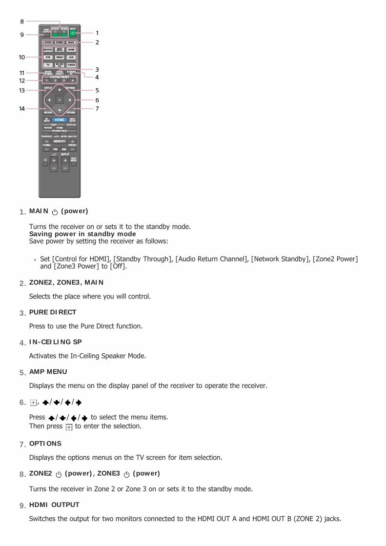
MAIN (power)
Turns the receiver on or sets it to the standby mode.Saving power in standby modeSave power by setting the receiver as follows:
Set [Control for HDMI], [Standby Through], [Audio Return Channel], [Network Standby], [Zone2 Power]and [Zone3 Power] to [Off].
1.
ZONE2, ZONE3, MAIN
Selects the place where you will control.
2.
PURE DIRECT
Press to use the Pure Direct function.
3.
IN-CEILING SP
Activates the In-Ceiling Speaker Mode.
4.
AMP MENU
Displays the menu on the display panel of the receiver to operate the receiver.
5.
, / / /
Press / / / to select the menu items.Then press to enter the selection.
6.
OPTIONS
Displays the options menus on the TV screen for item selection.
7.
ZONE2 (power), ZONE3 (power)
Turns the receiver in Zone 2 or Zone 3 on or sets it to the standby mode.
8.
HDMI OUTPUT
Switches the output for two monitors connected to the HDMI OUT A and HDMI OUT B (ZONE 2) jacks.
9.

NoteThe above explanations are intended to serve as examples.
[9] Parts and Controls Remote control
Remote control (lower section)
Use the supplied remote control to operate this receiver.
Input buttons
Select the device you want to use.When you press any of the input buttons, the receiver turns on.
10.
SOUND OPTIMIZER
Press to use the Sound Optimizer function to enjoy clear and dynamic sound at low volume levels.
11.
CUSTOM PRESET (1, 2, 3, 4)
Saves and recalls various settings for the receiver.
12.
DISPLAY
Displays information on the TV screen.
13.
RETURN
Returns to the previous menu.
14.
HOME
Displays the home menu on the TV screen.
1.
NoteThe above explanations are intended to serve as examples.
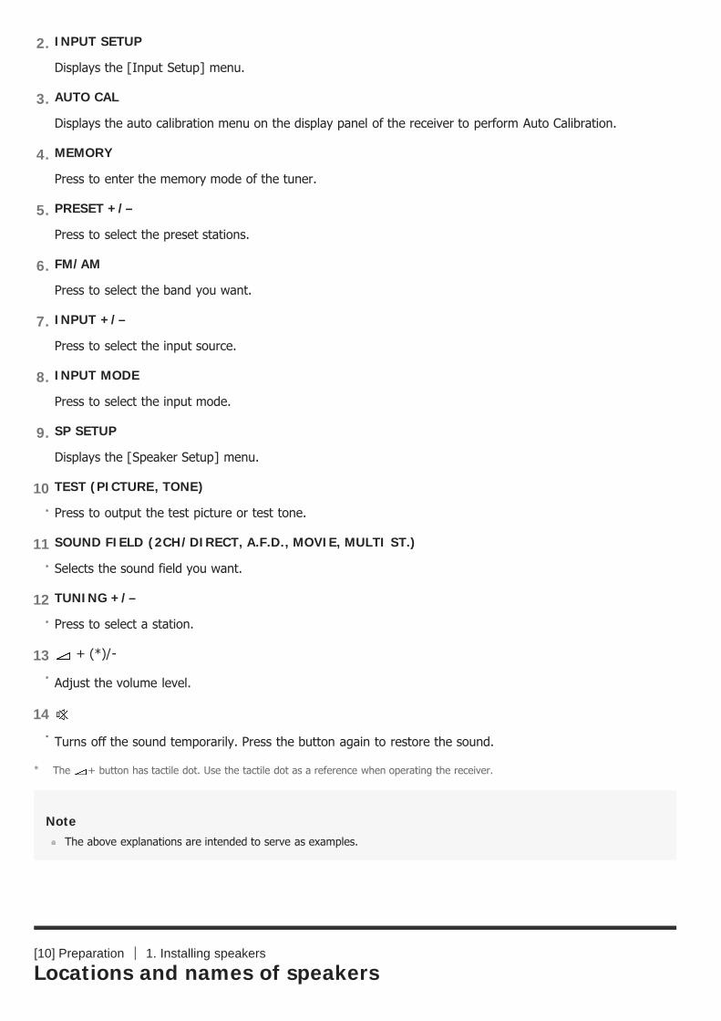
[10] Preparation 1. Installing speakers
Locations and names of speakers
INPUT SETUP
Displays the [Input Setup] menu.
2.
AUTO CAL
Displays the auto calibration menu on the display panel of the receiver to perform Auto Calibration.
3.
MEMORY
Press to enter the memory mode of the tuner.
4.
PRESET +/–
Press to select the preset stations.
5.
FM/AM
Press to select the band you want.
6.
INPUT +/–
Press to select the input source.
7.
INPUT MODE
Press to select the input mode.
8.
SP SETUP
Displays the [Speaker Setup] menu.
9.
TEST (PICTURE, TONE)
Press to output the test picture or test tone.
10.
SOUND FIELD (2CH/DIRECT, A.F.D., MOVIE, MULTI ST.)
Selects the sound field you want.
11.
TUNING +/–
Press to select a station.
12.
+ (*)/-
Adjust the volume level.
13.
Turns off the sound temporarily. Press the button again to restore the sound.
14.
The + button has tactile dot. Use the tactile dot as a reference when operating the receiver.*

Location of each speaker
Abbreviations used in illustrations Speaker name
FL Front left speaker
FR Front right speaker
CNT Center speaker
SL Surround left speaker
SR Surround right speaker
SBL Surround back left speaker
SBR Surround back right speaker
SB Surround back speaker
SW Subwoofer
TFL Top front left speaker
TFR Top front right speaker
TML Top middle left speaker
TMR Top middle right speaker
TRL Top rear left speaker
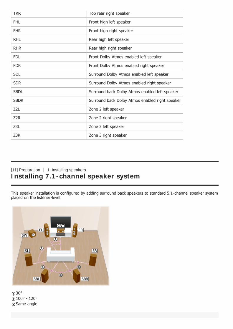
[11] Preparation 1. Installing speakers
Installing 7.1-channel speaker system
This speaker installation is configured by adding surround back speakers to standard 5.1-channel speaker systemplaced on the listener-level.
30°100° - 120°Same angle
TRR Top rear right speaker
FHL Front high left speaker
FHR Front high right speaker
RHL Rear high left speaker
RHR Rear high right speaker
FDL Front Dolby Atmos enabled left speaker
FDR Front Dolby Atmos enabled right speaker
SDL Surround Dolby Atmos enabled left speaker
SDR Surround Dolby Atmos enabled right speaker
SBDL Surround back Dolby Atmos enabled left speaker
SBDR Surround back Dolby Atmos enabled right speaker
Z2L Zone 2 left speaker
Z2R Zone 2 right speaker
Z3L Zone 3 left speaker
Z3R Zone 3 right speaker
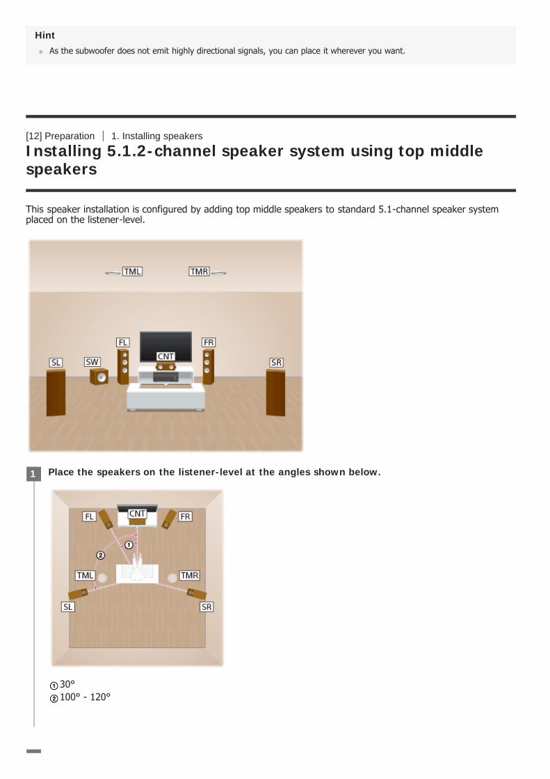
HintAs the subwoofer does not emit highly directional signals, you can place it wherever you want.
[12] Preparation 1. Installing speakers
Installing 5.1.2-channel speaker system using top middlespeakers
This speaker installation is configured by adding top middle speakers to standard 5.1-channel speaker systemplaced on the listener-level.
Place the speakers on the listener-level at the angles shown below.
30°100° - 120°
1

HintAs the subwoofer does not emit highly directional signals, you can place it wherever you want.
[13] Preparation 1. Installing speakers
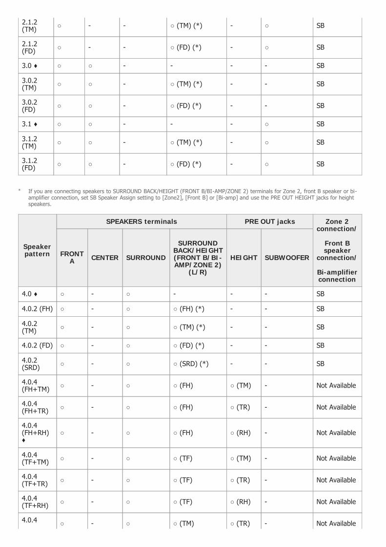
Installing 5.1.4-channel speaker system using top front andtop rear speakers with an additional stereo power amplifier(for STR-ZA3100ES/STR-ZA2100ES)
This speaker installation is configured by adding top front speakers and top rear speakers to 5.1-channel speakersystem placed on the listener-level. An additional stereo power amplifier is used for the top rear speakers.
Install the overhead (top) speakers at the angles shown below.
65° - 100°
2
Place the speakers on the listener-level at the angles shown below.1
HintAs the subwoofer does not emit highly directional signals, you can place it wherever you want.
[14] Preparation 1. Installing speakers
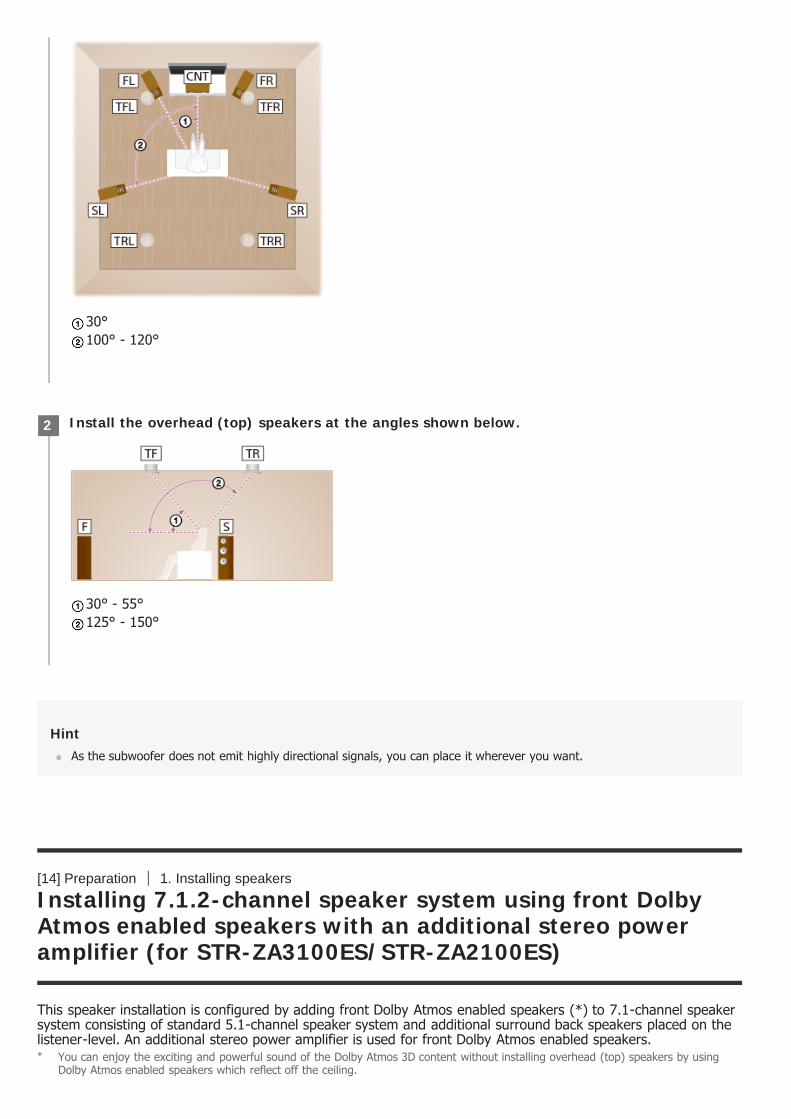
Installing 7.1.2-channel speaker system using front DolbyAtmos enabled speakers with an additional stereo poweramplifier (for STR-ZA3100ES/STR-ZA2100ES)
This speaker installation is configured by adding front Dolby Atmos enabled speakers (*) to 7.1-channel speakersystem consisting of standard 5.1-channel speaker system and additional surround back speakers placed on thelistener-level. An additional stereo power amplifier is used for front Dolby Atmos enabled speakers.
30°100° - 120°
Install the overhead (top) speakers at the angles shown below.
30° - 55°125° - 150°
2
You can enjoy the exciting and powerful sound of the Dolby Atmos 3D content without installing overhead (top) speakers by usingDolby Atmos enabled speakers which reflect off the ceiling.
*

30°100° - 120°Same angle
HintAs the subwoofer does not emit highly directional signals, you can place it wherever you want.
[15] Preparation 1. Installing speakers
Installing 5.1-channel speaker system with Zone 2connection
This speaker installation shows configurations in the main zone and Zone 2. In the main zone, 5.1-channelspeaker system placed on the listener-level is installed, and another pair of speakers is installed in Zone 2.
30°100° - 120°
Hint

As the subwoofer does not emit highly directional signals, you can place it wherever you want.
[16] Preparation 1. Installing speakers
Installing 5.1.2-channel speaker system with bi-amplifierconnection (for STR-ZA3100ES/STR-ZA2100ES)
In this speaker installation, top middle speakers are added to a 5.1-channel speaker system in a bi-amplifiedconfiguration at the listener’s level.You can enhance the sound quality of the front speakers by separately connecting the built-in amplifiers totweeters and woofers in a bi-amplifier configuration.
Place the speakers on the listener-level at the angles shown below.
30°100° - 120°
1
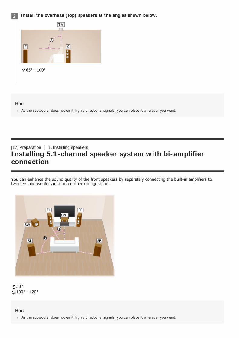
HintAs the subwoofer does not emit highly directional signals, you can place it wherever you want.
[17] Preparation 1. Installing speakers
Installing 5.1-channel speaker system with bi-amplifierconnection
You can enhance the sound quality of the front speakers by separately connecting the built-in amplifiers totweeters and woofers in a bi-amplifier configuration.
30°100° - 120°
HintAs the subwoofer does not emit highly directional signals, you can place it wherever you want.
Install the overhead (top) speakers at the angles shown below.
65° - 100°
2

[18] Preparation 1. Installing speakers
Speaker configuration and speaker pattern settings
Select the speaker pattern using [Speaker Pattern] in the [Setup] - [Speaker Setup] menu according to thespeaker configuration which you are using.
[19] Preparation 2. Connecting speakers
Connecting 7.1-channel speaker system
Connect each speaker as illustrated below.Before connecting cables, be sure to disconnect the AC power cord (mains lead).For details on how to connect speaker cables to the receiver, see “How to connect speaker cables.”
Speaker configuration in each zone [SBSpeakerAssign]
(*)
Speaker pattern tobe selected in
[Speaker Pattern]Main zone Zone2
7.1-channel speaker system Notused [Off] [7.1]
5.1.2-channel speaker system using top middle speakers Notused [Off] [5.1.2 (TM)]
5.1.4-channel speaker system using top front and top rearspeakers with an additional stereo power amplifier (for STR-ZA3100ES/STR-ZA2100ES)
Notused [Off] [5.1.4 (TF+TR)]
7.1.2-channel speaker system using front Dolby Atmos enabledspeakers with an additional stereo power amplifier (for STR-ZA3100ES/STR-ZA2100ES)
Notused [Off] [7.1.2 (FD)]
5.1-channel speaker system with Zone 2 connection 2-channel [Zone2] [5.1]
5.1.2-channel speaker system with bi-amplifier connection (forSTR-ZA3100ES/STR-ZA2100ES)
Notused [Bi-Amp] [5.1.2 (TM)]
5.1-channel speaker system with bi-amplifier connection Notused [Bi-Amp] [5.1]
You can only set [SB Speaker Assign] if a speaker pattern in which speakers are not connected to the SPEAKERS SURROUNDBACK/HEIGHT (FRONT B/BI-AMP/ZONE 2) terminals is selected.
*

Monaural audio cable (not supplied) Speaker cable (not supplied)
NoteAfter you have installed and connected your speakers, set the speaker pattern to [7.1] using [Speaker Pattern] in the[Speaker Setup] menu.
Connect speaker cables properly with the polarities (+/–) matched between the speaker cables and the SPEAKERSterminals.
[20] Preparation 2. Connecting speakers
Connecting 5.1.2-channel speaker system using top middlespeakers
Connect each speaker as illustrated below.Before connecting cables, be sure to disconnect the AC power cord (mains lead).For details on how to connect speaker cables to the receiver, see “How to connect speaker cables.”

Monaural audio cable (not supplied) Speaker cable (not supplied)
NoteAfter you have installed and connected your speakers, set the speaker pattern to [5.1.2 (TM)] using [Speaker Pattern] inthe [Speaker Setup] menu.
Connect speaker cables properly with the polarities (+/–) matched between the speaker cables and the SPEAKERSterminals.
[21] Preparation 2. Connecting speakers
Connecting 5.1.4-channel speaker system using top frontand top rear speakers with an additional stereo poweramplifier (for STR-ZA3100ES/STR-ZA2100ES)
Connect each speaker as illustrated below.Before connecting cables, be sure to disconnect the AC power cord (mains lead).For details on how to connect speaker cables to the receiver, see “How to connect speaker cables.”

Monaural audio cable (not supplied) Speaker cable (not supplied) Audio cable (not supplied) Stereo power amplifier (not supplied)
NoteAfter you have installed and connected your speakers, set the speaker pattern to [5.1.4 (TF+TR)] using [SpeakerPattern] in the [Speaker Setup] menu.
Connect speaker cables properly with the polarities (+/–) matched between the speaker cables and the SPEAKERSterminals.
[22] Preparation 2. Connecting speakers
Connecting 7.1.2-channel speaker system using front DolbyAtmos enabled speakers with an additional stereo poweramplifier (for STR-ZA3100ES/STR-ZA2100ES)
Connect each speaker as illustrated below.Before connecting cables, be sure to disconnect the AC power cord (mains lead).For details on how to connect speaker cables to the receiver, see “How to connect speaker cables.”

Monaural audio cable (not supplied) Speaker cable (not supplied) Audio cable (not supplied) Stereo power amplifier (not supplied)
NoteAfter you have installed and connected your speakers, set the speaker pattern to [7.1.2 (FD)] using [Speaker Pattern] inthe [Speaker Setup] menu.
Connect speaker cables properly with the polarities (+/–) matched between the speaker cables and the SPEAKERSterminals.
[23] Preparation 2. Connecting speakers
Connecting 5.1-channel speaker system with Zone 2connection
Connect each speaker as illustrated below.Before connecting cables, be sure to disconnect the AC power cord (mains lead).For details on how to connect speaker cables to the receiver, see “How to connect speaker cables.”

Monaural audio cable (not supplied) Speaker cable (not supplied)
After you have made the Zone 2 speaker connection, set [SB Speaker Assign] to [Zone2] in the [Speaker Setup]menu.
NoteAfter you have installed and connected your speakers, set the speaker pattern to [5.1] using [Speaker Pattern] in the[Speaker Setup] menu.
You can only set [SB Speaker Assign] if a speaker pattern in which speakers are not connected to the SPEAKERSSURROUND BACK/HEIGHT(FRONT B/BI-AMP/ZONE 2) terminals is selected.
Connect speaker cables properly with the polarities (+/–) matched between the speaker cables and the SPEAKERSterminals.
[24] Preparation 2. Connecting speakers
Connecting 5.1.2-channel speaker system with bi-amplifierconnection (for STR-ZA3100ES/STR-ZA2100ES)
You can enhance the sound quality of the front speakers by separately connecting the built-in amplifiers totweeters and woofers in a bi-amplifier configuration.If a speaker pattern in which speakers are not connected to the SPEAKERS SURROUND BACK/HEIGHT(FRONTB/BI-AMP/ZONE 2) terminals is selected, you can connect front speakers to those terminals for bi-amplifierconnection. Connect each speaker as illustrated below. Before connecting cables, be sure to disconnect the AC power cord (mains lead). For details on how to connect speaker cables to the receiver, see “How to connect speaker cables.”
Connecting front speakers with bi-amplifier connection

Connect the jacks on the Lo (or Hi) side of the front speakers to the SPEAKERS FRONT A terminals, and connectthe jacks on the Hi (or Lo) side of the front speakers to the SPEAKERS SURROUND BACK/HEIGHT(FRONT B/BI-AMP/ZONE 2) terminals.Make sure that metal fittings of Hi/Lo attached to the speakers have been removed from the speakers to avoidreceiver malfunction.
Speaker cable (not supplied)
Connecting speakers other than front speakers
Monaural audio cable (not supplied) Speaker cable (not supplied)

Audio cable (not supplied) Stereo power amplifier (not supplied)
After you have made the bi-amplifier connection, set [SB Speaker Assign] to [Bi-Amp] in the [Speaker Setup]menu.
NoteAfter you have installed and connected your speakers, set the speaker pattern to [5.1.2 (TM)] using [Speaker Pattern] inthe [Speaker Setup] menu.
You can only set [SB Speaker Assign] if a speaker pattern in which speakers are not connected to the SPEAKERSSURROUND BACK/HEIGHT(FRONT B/BI-AMP/ZONE 2) terminals is selected.
Connect speaker cables properly with the polarities (+/–) matched between the speaker cables and the SPEAKERSterminals.
[25] Preparation 2. Connecting speakers
Connecting 5.1-channel speaker system with bi-amplifierconnection
You can enhance the sound quality of the front speakers by separately connecting the built-in amplifiers totweeters and woofers in a bi-amplifier configuration.If a speaker pattern in which speakers are not connected to the SPEAKERS SURROUND BACK/HEIGHT(FRONTB/BI-AMP/ZONE 2) terminals is selected, you can connect front speakers to those terminals for bi-amplifierconnection. Connect each speaker as illustrated below. Before connecting cables, be sure to disconnect the AC power cord (mains lead). For details on how to connect speaker cables to the receiver, see “How to connect speaker cables.”
Connecting front speakers with bi-amplifier connection
Connect the jacks on the Lo (or Hi) side of the front speakers to the SPEAKERS FRONT A terminals, and connectthe jacks on the Hi (or Lo) side of the front speakers to the SPEAKERS SURROUND BACK/HEIGHT(FRONT B/BI-AMP/ZONE 2) terminals.Make sure that metal fittings of Hi/Lo attached to the speakers have been removed from the speakers to avoidreceiver malfunction.

Speaker cable (not supplied)
Connecting speakers other than front speakers
Monaural audio cable (not supplied) Speaker cable (not supplied)
After you have made the bi-amplifier connection, set [SB Speaker Assign] to [Bi-Amp] in the [Speaker Setup]menu.
NoteAfter you have installed and connected your speakers, set the speaker pattern to [5.1] using [Speaker Pattern] in the[Speaker Setup] menu.
You can only set [SB Speaker Assign] if a speaker pattern in which speakers are not connected to the SPEAKERSSURROUND BACK/HEIGHT(FRONT B/BI-AMP/ZONE 2) terminals is selected.

Connect speaker cables properly with the polarities (+/–) matched between the speaker cables and the SPEAKERSterminals.
[26] Preparation 2. Connecting speakers
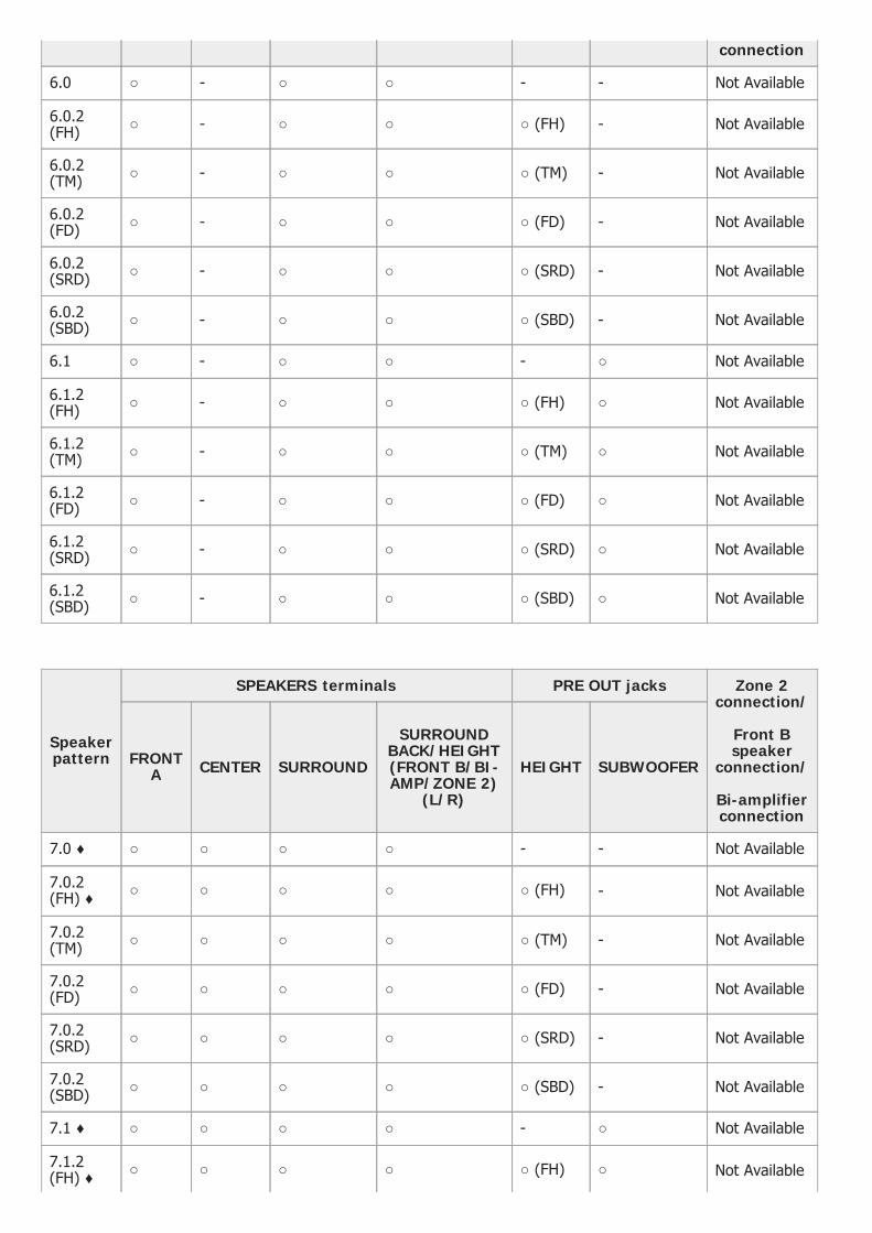
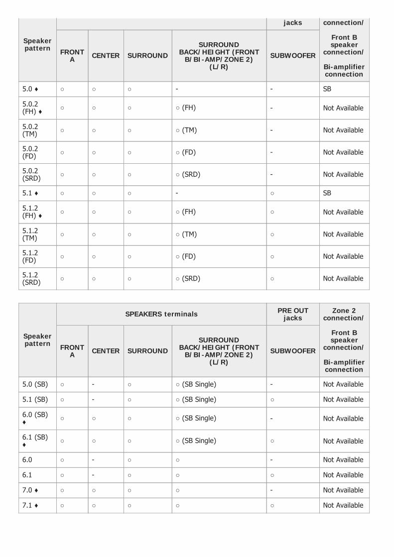
Speaker patterns and terminals to be connected (for STR-ZA3100ES/STR-ZA2100ES)
When you connect speakers to the receiver, refer to the following table. You can use the following table to confirm the speaker patterns supported by the receiver as well as the speakerterminals to which the speakers of each speaker pattern are to be connected. When playing back DTS content, select a speaker pattern which supports DTS playback (*), indicated with ♦below. If you select other speaker patterns, the sound may not be output from some speakers.To set the speaker pattern, select [Setup] - [Speaker Setup] - [Speaker Pattern] from the home menu.
The abbreviations and symbol used in the list are as follows.
FH: Front high speakersTF: Top front speakersTM: Top middle speakersTR: Top rear speakersRH: Rear high speakersFD: Front Dolby Atmos enabled speakersSRD: Surround Dolby Atmos enabled speakersSBD: Surround back Dolby Atmos enabled speakersSB: SPEAKERS SURROUND BACK/HEIGHT (FRONT B/BI-AMP/ZONE 2) terminals
What the numbers in the speaker pattern indicate:
Number of speakers located at listener’s level Number of subwoofers Number of height or overhead (top) speakers
Due to the receiver’s system limitations*
Speakerpattern
SPEAKERS terminals PRE OUT jacks Zone 2connection/
Front Bspeaker
connection/
Bi-amplifierconnection
FRONTA CENTER SURROUND
SURROUNDBACK/HEIGHT(FRONT B/BI-AMP/ZONE 2)
(L/R)
HEIGHT SUBWOOFER
2.0 ♦ ○ - - - - - SB
2.0.2(TM) ○ - - ○ (TM) (*) - - SB
2.0.2(FD) ○ - - ○ (FD) (*) - - SB
2.1 ♦ ○ - - - - ○ SB
2.1.2(TM) ○ - - ○ (TM) (*) - ○ SB
2.1.2(FD) ○ - - ○ (FD) (*) - ○ SB
3.0 ♦ ○ ○ - - - - SB
3.0.2(TM) ○ ○ - ○ (TM) (*) - - SB
3.0.2(FD) ○ ○ - ○ (FD) (*) - - SB
3.1 ♦ ○ ○ - - - ○ SB
3.1.2(TM) ○ ○ - ○ (TM) (*) - ○ SB
3.1.2(FD) ○ ○ - ○ (FD) (*) - ○ SB
If you are connecting speakers to SURROUND BACK/HEIGHT (FRONT B/BI-AMP/ZONE 2) terminals for Zone 2, front B speaker or bi-amplifier connection, set SB Speaker Assign setting to [Zone2], [Front B] or [Bi-amp] and use the PRE OUT HEIGHT jacks for heightspeakers.
*
Speakerpattern
SPEAKERS terminals PRE OUT jacks Zone 2connection/
Front Bspeaker
connection/
Bi-amplifierconnection
FRONTA CENTER SURROUND
SURROUNDBACK/HEIGHT(FRONT B/BI-AMP/ZONE 2)
(L/R)
HEIGHT SUBWOOFER
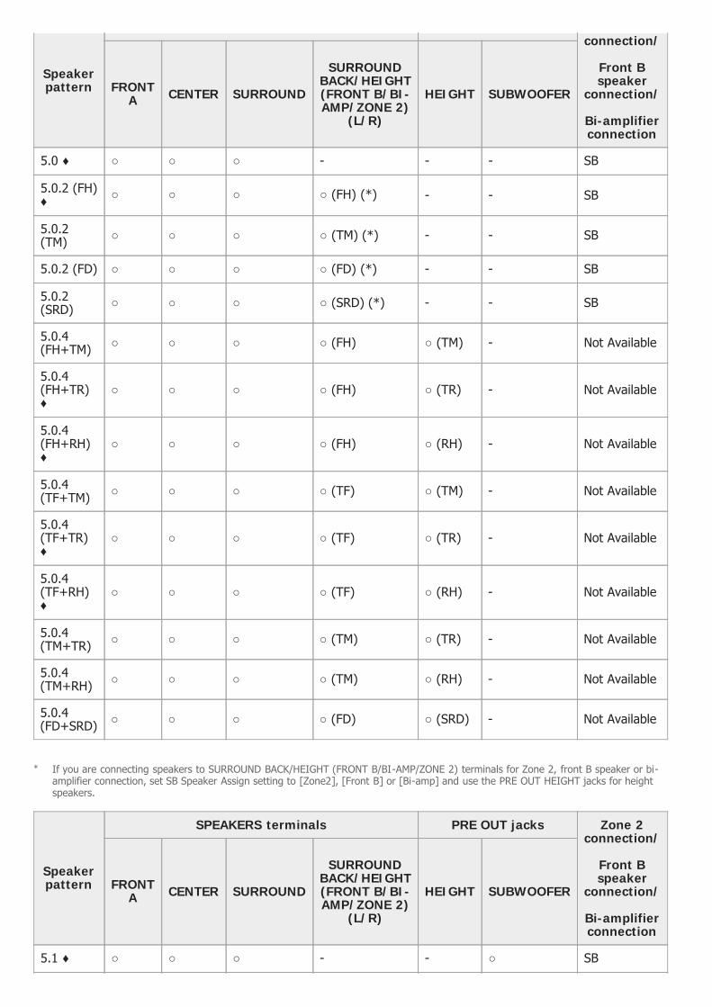
4.0 ♦ ○ - ○ - - - SB
4.0.2 (FH) ○ - ○ ○ (FH) (*) - - SB
4.0.2(TM) ○ - ○ ○ (TM) (*) - - SB
4.0.2 (FD) ○ - ○ ○ (FD) (*) - - SB
4.0.2(SRD) ○ - ○ ○ (SRD) (*) - - SB
4.0.4(FH+TM) ○ - ○ ○ (FH) ○ (TM) - Not Available
4.0.4(FH+TR) ○ - ○ ○ (FH) ○ (TR) - Not Available
4.0.4(FH+RH)♦
○ - ○ ○ (FH) ○ (RH) - Not Available
4.0.4(TF+TM) ○ - ○ ○ (TF) ○ (TM) - Not Available
4.0.4(TF+TR) ○ - ○ ○ (TF) ○ (TR) - Not Available
4.0.4(TF+RH) ○ - ○ ○ (TF) ○ (RH) - Not Available
4.0.4 ○ - ○ ○ (TM) ○ (TR) - Not Available

(TM+TR)
4.0.4(TM+RH) ○ - ○ ○ (TM) ○ (RH) - Not Available
4.0.4(FD+SRD) ○ - ○ ○ (FD) ○ (SRD) - Not Available
If you are connecting speakers to SURROUND BACK/HEIGHT (FRONT B/BI-AMP/ZONE 2) terminals for Zone 2, front B speaker or bi-amplifier connection, set SB Speaker Assign setting to [Zone2], [Front B] or [Bi-amp] and use the PRE OUT HEIGHT jacks for heightspeakers.
*
Speakerpattern
SPEAKERS terminals PRE OUT jacks Zone 2connection/
Front Bspeaker
connection/
Bi-amplifierconnection
FRONTA CENTER SURROUND
SURROUNDBACK/HEIGHT(FRONT B/BI-AMP/ZONE 2)
(L/R)
HEIGHT SUBWOOFER
4.1 ♦ ○ - ○ - - ○ SB
4.1.2 (FH) ○ - ○ ○ (FH) (*) - ○ SB
4.1.2(TM) ○ - ○ ○ (TM) (*) - ○ SB
4.1.2 (FD) ○ - ○ ○ (FD) (*) - ○ SB
4.1.2(SRD) ○ - ○ ○ (SRD) (*) - ○ SB
4.1.4(FH+TM) ○ - ○ ○ (FH) ○ (TM) ○ Not Available
4.1.4(FH+TR) ○ - ○ ○ (FH) ○ (TR) ○ Not Available
4.1.4(FH+RH)♦
○ - ○ ○ (FH) ○ (RH) ○ Not Available
4.1.4(TF+TM) ○ - ○ ○ (TF) ○ (TM) ○ Not Available
4.1.4(TF+TR) ○ - ○ ○ (TF) ○ (TR) ○ Not Available
4.1.4(TF+RH) ○ - ○ ○ (TF) ○ (RH) ○ Not Available
4.1.4(TM+TR) ○ - ○ ○ (TM) ○ (TR) ○ Not Available
4.1.4(TM+RH) ○ - ○ ○ (TM) ○ (RH) ○ Not Available
4.1.4(FD+SRD) ○ - ○ ○ (FD) ○ (SRD) ○ Not Available
If you are connecting speakers to SURROUND BACK/HEIGHT (FRONT B/BI-AMP/ZONE 2) terminals for Zone 2, front B speaker or bi-amplifier connection, set SB Speaker Assign setting to [Zone2], [Front B] or [Bi-amp] and use the PRE OUT HEIGHT jacks for heightspeakers.
*
SPEAKERS terminals PRE OUT jacks Zone 2
Speakerpattern
connection/
Front Bspeaker
connection/
Bi-amplifierconnection
FRONTA CENTER SURROUND
SURROUNDBACK/HEIGHT(FRONT B/BI-AMP/ZONE 2)
(L/R)
HEIGHT SUBWOOFER
5.0 ♦ ○ ○ ○ - - - SB
5.0.2 (FH)♦ ○ ○ ○ ○ (FH) (*) - - SB
5.0.2(TM) ○ ○ ○ ○ (TM) (*) - - SB
5.0.2 (FD) ○ ○ ○ ○ (FD) (*) - - SB
5.0.2(SRD) ○ ○ ○ ○ (SRD) (*) - - SB
5.0.4(FH+TM) ○ ○ ○ ○ (FH) ○ (TM) - Not Available
5.0.4(FH+TR)♦
○ ○ ○ ○ (FH) ○ (TR) - Not Available
5.0.4(FH+RH)♦
○ ○ ○ ○ (FH) ○ (RH) - Not Available
5.0.4(TF+TM) ○ ○ ○ ○ (TF) ○ (TM) - Not Available
5.0.4(TF+TR)♦
○ ○ ○ ○ (TF) ○ (TR) - Not Available
5.0.4(TF+RH)♦
○ ○ ○ ○ (TF) ○ (RH) - Not Available
5.0.4(TM+TR) ○ ○ ○ ○ (TM) ○ (TR) - Not Available
5.0.4(TM+RH) ○ ○ ○ ○ (TM) ○ (RH) - Not Available
5.0.4(FD+SRD) ○ ○ ○ ○ (FD) ○ (SRD) - Not Available
If you are connecting speakers to SURROUND BACK/HEIGHT (FRONT B/BI-AMP/ZONE 2) terminals for Zone 2, front B speaker or bi-amplifier connection, set SB Speaker Assign setting to [Zone2], [Front B] or [Bi-amp] and use the PRE OUT HEIGHT jacks for heightspeakers.
*
Speakerpattern
SPEAKERS terminals PRE OUT jacks Zone 2connection/
Front Bspeaker
connection/
Bi-amplifierconnection
FRONTA CENTER SURROUND
SURROUNDBACK/HEIGHT(FRONT B/BI-AMP/ZONE 2)
(L/R)
HEIGHT SUBWOOFER
5.1 ♦ ○ ○ ○ - - ○ SB

5.1.2 (FH)♦ ○ ○ ○ ○ (FH) (*) - ○ SB
5.1.2(TM) ○ ○ ○ ○ (TM) (*) - ○ SB
5.1.2 (FD) ○ ○ ○ ○ (FD) (*) - ○ SB
5.1.2(SRD) ○ ○ ○ ○ (SRD) (*) - ○ SB
5.1.4(FH+TM) ○ ○ ○ ○ (FH) ○ (TM) ○ Not Available
5.1.4(FH+TR)♦
○ ○ ○ ○ (FH) ○ (TR) ○ Not Available
5.1.4(FH+RH)♦
○ ○ ○ ○ (FH) ○ (RH) ○ Not Available
5.1.4(TF+TM) ○ ○ ○ ○ (TF) ○ (TM) ○ Not Available
5.1.4(TF+TR)♦
○ ○ ○ ○ (TF) ○ (TR) ○ Not Available
5.1.4(TF+RH)♦
○ ○ ○ ○ (TF) ○ (RH) ○ Not Available
5.1.4(TM+TR) ○ ○ ○ ○ (TM) ○ (TR) ○ Not Available
5.1.4(TM+RH) ○ ○ ○ ○ (TM) ○ (RH) ○ Not Available
5.1.4(FD+SRD) ○ ○ ○ ○ (FD) ○ (SRD) ○ Not Available
If you are connecting speakers to SURROUND BACK/HEIGHT (FRONT B/BI-AMP/ZONE 2) terminals for Zone 2, front B speaker or bi-amplifier connection, set SB Speaker Assign setting to [Zone2], [Front B] or [Bi-amp] and use the PRE OUT HEIGHT jacks for heightspeakers.
*
Speakerpattern
SPEAKERS terminals PRE OUT jacks Zone 2connection/
Front Bspeaker
connection/
Bi-amplifierconnection
FRONTA CENTER SURROUND
SURROUNDBACK/HEIGHT(FRONT B/BI-AMP/ZONE 2)
(L/R)
HEIGHT SUBWOOFER
5.0 (SB) ○ - ○ ○ (SB Single) - - Not Available
5.0.2(SB+FH) ○ - ○ ○ (SB Single) ○ (FH) - Not Available
5.0.2(SB+TM) ○ - ○ ○ (SB Single) ○ (TM) - Not Available
5.0.2(SB+FD) ○ - ○ ○ (SB Single) ○ (FD) - Not Available
5.0.2

(SB+SRD) ○ - ○ ○ (SB Single) ○ (SRD) - Not Available
5.1 (SB) ○ - ○ ○ (SB Single) - ○ Not Available
5.1.2(SB+FH) ○ - ○ ○ (SB Single) ○ (FH) ○ Not Available
5.1.2(SB+TM) ○ - ○ ○ (SB Single) ○ (TM) ○ Not Available
5.1.2(SB+FD) ○ - ○ ○ (SB Single) ○ (FD) ○ Not Available
5.1.2(SB+SRD) ○ - ○ ○ (SB Single) ○ (SRD) ○ Not Available
Speakerpattern
SPEAKERS terminals PRE OUT jacks Zone 2connection/
Front Bspeaker
connection/
Bi-amplifierconnection
FRONTA CENTER SURROUND
SURROUNDBACK/HEIGHT(FRONT B/BI-AMP/ZONE 2)
(L/R)
HEIGHT SUBWOOFER
6.0 (SB)♦ ○ ○ ○ ○ (SB Single) - - Not Available
6.0.2(SB+FH) ○ ○ ○ ○ (SB Single) ○ (FH) - Not Available
6.0.2(SB+TM) ○ ○ ○ ○ (SB Single) ○ (TM) - Not Available
6.0.2(SB+FD) ○ ○ ○ ○ (SB Single) ○ (FD) - Not Available
6.0.2(SB+SRD) ○ ○ ○ ○ (SB Single) ○ (SRD) - Not Available
6.1 (SB)♦ ○ ○ ○ ○ (SB Single) - ○ Not Available
6.1.2(SB+FH) ○ ○ ○ ○ (SB Single) ○ (FH) ○ Not Available
6.1.2(SB+TM) ○ ○ ○ ○ (SB Single) ○ (TM) ○ Not Available
6.1.2(SB+FD) ○ ○ ○ ○ (SB Single) ○ (FD) ○ Not Available
6.1.2(SB+SRD) ○ ○ ○ ○ (SB Single) ○ (SRD) ○ Not Available
Speakerpattern
SPEAKERS terminals PRE OUT jacks Zone 2connection/
Front Bspeaker
connection/
Bi-amplifier
FRONTA CENTER SURROUND
SURROUNDBACK/HEIGHT(FRONT B/BI-AMP/ZONE 2)
(L/R)
HEIGHT SUBWOOFER
connection
6.0 ○ - ○ ○ - - Not Available
6.0.2(FH) ○ - ○ ○ ○ (FH) - Not Available
6.0.2(TM) ○ - ○ ○ ○ (TM) - Not Available
6.0.2(FD) ○ - ○ ○ ○ (FD) - Not Available
6.0.2(SRD) ○ - ○ ○ ○ (SRD) - Not Available
6.0.2(SBD) ○ - ○ ○ ○ (SBD) - Not Available
6.1 ○ - ○ ○ - ○ Not Available
6.1.2(FH) ○ - ○ ○ ○ (FH) ○ Not Available
6.1.2(TM) ○ - ○ ○ ○ (TM) ○ Not Available
6.1.2(FD) ○ - ○ ○ ○ (FD) ○ Not Available
6.1.2(SRD) ○ - ○ ○ ○ (SRD) ○ Not Available
6.1.2(SBD) ○ - ○ ○ ○ (SBD) ○ Not Available
Speakerpattern
SPEAKERS terminals PRE OUT jacks Zone 2connection/
Front Bspeaker
connection/
Bi-amplifierconnection
FRONTA CENTER SURROUND
SURROUNDBACK/HEIGHT(FRONT B/BI-AMP/ZONE 2)
(L/R)
HEIGHT SUBWOOFER
7.0 ♦ ○ ○ ○ ○ - - Not Available
7.0.2(FH) ♦ ○ ○ ○ ○ ○ (FH) - Not Available
7.0.2(TM) ○ ○ ○ ○ ○ (TM) - Not Available
7.0.2(FD) ○ ○ ○ ○ ○ (FD) - Not Available
7.0.2(SRD) ○ ○ ○ ○ ○ (SRD) - Not Available
7.0.2(SBD) ○ ○ ○ ○ ○ (SBD) - Not Available
7.1 ♦ ○ ○ ○ ○ - ○ Not Available
7.1.2(FH) ♦ ○ ○ ○ ○ ○ (FH) ○ Not Available

[27] Preparation 2. Connecting speakers
Speaker patterns and terminals to be connected (for STR-ZA1100ES)
When you connect speakers to the receiver, refer to the following table. You can use the following table to confirm the speaker patterns supported by the receiver as well as the speakerterminals to which the speakers of each speaker pattern are to be connected. When playing back DTS content, select a speaker pattern which supports DTS playback (*), indicated with ♦below. If you select other speaker patterns, the sound may not be output from some speakers.To set the speaker pattern, select [Setup] - [Speaker Setup] - [Speaker Pattern] from the home menu.
The abbreviations and symbol used in the list are as follows.
FH: Front high speakersTM: Top middle speakersFD: Front Dolby Atmos enabled speakersSRD: Surround Dolby Atmos enabled speakersSB: SPEAKERS SURROUND BACK/HEIGHT (FRONT B/BI-AMP/ZONE 2) terminals
What the numbers in the speaker pattern indicate:
Number of speakers located at listener’s level Number of subwoofers Number of height or overhead (top) speakers
7.1.2(TM) ○ ○ ○ ○ ○ (TM) ○ Not Available
7.1.2(FD) ○ ○ ○ ○ ○ (FD) ○ Not Available
7.1.2(SRD) ○ ○ ○ ○ ○ (SRD) ○ Not Available
7.1.2(SBD) ○ ○ ○ ○ ○ (SBD) ○ Not Available
Due to the receiver’s system limitations*
Speakerpattern
SPEAKERS terminals PRE OUTjacks
Zone 2connection/
Front Bspeaker
connection/
Bi-amplifierconnection
FRONTA CENTER SURROUND
SURROUNDBACK/HEIGHT (FRONT
B/BI-AMP/ZONE 2)(L/R)
SUBWOOFER
2.0 ♦ ○ - - - - SB
2.0.2(TM) ○ - - ○ (TM) - Not Available

2.0.2(FD) ○ - - ○ (FD) - Not Available
2.1 ♦ ○ - - - ○ SB
2.1.2(TM) ○ - - ○ (TM) ○ Not Available
2.1.2(FD) ○ - - ○ (FD) ○ Not Available
3.0 ♦ ○ ○ - - - SB
3.0.2(TM) ○ ○ - ○ (TM) - Not Available
3.0.2(FD) ○ ○ - ○ (FD) - Not Available
3.1 ♦ ○ ○ - - ○ SB
3.1.2(TM) ○ ○ - ○ (TM) ○ Not Available
3.1.2(FD) ○ ○ - ○ (FD) ○ Not Available
Speakerpattern
SPEAKERS terminals PRE OUTjacks
Zone 2connection/
Front Bspeaker
connection/
Bi-amplifierconnection
FRONTA CENTER SURROUND
SURROUNDBACK/HEIGHT (FRONT
B/BI-AMP/ZONE 2)(L/R)
SUBWOOFER
4.0 ♦ ○ - ○ - - SB
4.0.2(FH) ○ - ○ ○ (FH) - Not Available
4.0.2(TM) ○ - ○ ○ (TM) - Not Available
4.0.2(FD) ○ - ○ ○ (FD) - Not Available
4.0.2(SRD) ○ - ○ ○ (SRD) - Not Available
4.1 ♦ ○ - ○ - ○ SB
4.1.2(FH) ○ - ○ ○ (FH) ○ Not Available
4.1.2(TM) ○ - ○ ○ (TM) ○ Not Available
4.1.2(FD) ○ - ○ ○ (FD) ○ Not Available
4.1.2(SRD) ○ - ○ ○ (SRD) ○ Not Available
SPEAKERS terminals PRE OUT Zone 2
Speakerpattern
jacks connection/
Front Bspeaker
connection/
Bi-amplifierconnection
FRONTA CENTER SURROUND
SURROUNDBACK/HEIGHT (FRONT
B/BI-AMP/ZONE 2)(L/R)
SUBWOOFER
5.0 ♦ ○ ○ ○ - - SB
5.0.2(FH) ♦ ○ ○ ○ ○ (FH) - Not Available
5.0.2(TM) ○ ○ ○ ○ (TM) - Not Available
5.0.2(FD) ○ ○ ○ ○ (FD) - Not Available
5.0.2(SRD) ○ ○ ○ ○ (SRD) - Not Available
5.1 ♦ ○ ○ ○ - ○ SB
5.1.2(FH) ♦ ○ ○ ○ ○ (FH) ○ Not Available
5.1.2(TM) ○ ○ ○ ○ (TM) ○ Not Available
5.1.2(FD) ○ ○ ○ ○ (FD) ○ Not Available
5.1.2(SRD) ○ ○ ○ ○ (SRD) ○ Not Available
Speakerpattern
SPEAKERS terminals PRE OUTjacks
Zone 2connection/
Front Bspeaker
connection/
Bi-amplifierconnection
FRONTA CENTER SURROUND
SURROUNDBACK/HEIGHT (FRONT
B/BI-AMP/ZONE 2)(L/R)
SUBWOOFER
5.0 (SB) ○ - ○ ○ (SB Single) - Not Available
5.1 (SB) ○ - ○ ○ (SB Single) ○ Not Available
6.0 (SB)♦ ○ ○ ○ ○ (SB Single) - Not Available
6.1 (SB)♦ ○ ○ ○ ○ (SB Single) ○ Not Available
6.0 ○ - ○ ○ - Not Available
6.1 ○ - ○ ○ ○ Not Available
7.0 ♦ ○ ○ ○ ○ - Not Available
7.1 ♦ ○ ○ ○ ○ ○ Not Available

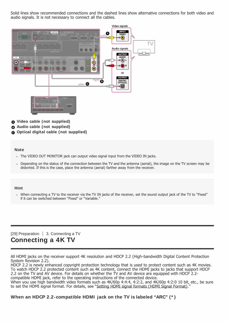
[28] Preparation 3. Connecting a TV
Connecting a TV
Connect a TV to the HDMI OUT or MONITOR OUT jack. You can operate this receiver using the menu on the TVscreen when you connect the TV to the HDMI OUT A jack.Be sure to disconnect the AC power cord (mains lead) before connecting cables.
Connecting a TV incompatible with the Audio Return Channel (ARC) function via anHDMI connection
Solid lines show recommended connections and the dashed lines show alternative connections for audio signals.It is not necessary to connect all the cables. HDMI connection for audio/video signals is required.
Optical digital cable (not supplied) Audio cable (not supplied) HDMI cable (not supplied)
NoteSony recommends that you use an HDMI cable made by Sony or another HDMI-authorized cable. Be sure to use a HighSpeed HDMI Cable with Ethernet. Premium High Speed HDMI Cable with Ethernet that supports 18 Gbps is required for4K/60p 4:4:4, 4:2:2, and 4K/60p 4:2:0 10 bit, etc.
Connecting a TV compatible with the Audio Return Channel (ARC) function via an HDMIconnection

With just one HDMI cable connection, you can listen to the TV audio from the speakers connected to thereceiver while the receiver sends audio and video to the TV.
HDMI cable (not supplied)
NoteSony recommends that you use an HDMI cable made by Sony or another HDMI-authorized cable. Be sure to use a HighSpeed HDMI Cable with Ethernet. Premium High Speed HDMI Cable with Ethernet that supports 18 Gbps is required for4K/60p 4:4:4, 4:2:2, and 4K/60p 4:2:0 10 bit, etc.
For this connection, you need to turn the Audio Return Channel function on. Press HOME to display the home menu,select [Setup] - [HDMI Setup], and set [Audio Return Channel] to [Standard].
HintIf the HDMI jack of the TV (labeled “ARC”) is already connected to another device, disconnect the device and connectthe receiver.
Connecting a TV and a projector
HDMI cable (not supplied)
NoteSony recommends that you use an HDMI cable made by Sony or another HDMI-authorized cable. Be sure to use a HighSpeed HDMI Cable with Ethernet. Premium High Speed HDMI Cable with Ethernet that supports 18 Gbps is required for4K/60p 4:4:4, 4:2:2, and 4K/60p 4:2:0 10 bit, etc.
To use this connection in only one room, select [Setup] - [HDMI Setup], and set [HDMI Out B Mode] to [Main].
Connecting a TV without HDMI jacks
Solid lines show recommended connections and the dashed lines show alternative connections for both video andaudio signals. It is not necessary to connect all the cables.
Video cable (not supplied) Audio cable (not supplied) Optical digital cable (not supplied)
NoteThe VIDEO OUT MONITOR jack can output video signal input from the VIDEO IN jacks.
Depending on the status of the connection between the TV and the antenna (aerial), the image on the TV screen may bedistorted. If this is the case, place the antenna (aerial) farther away from the receiver.
HintWhen connecting a TV to the receiver via the TV IN jacks of the receiver, set the sound output jack of the TV to “Fixed”if it can be switched between “Fixed” or “Variable.”
[29] Preparation 3. Connecting a TV
Connecting a 4K TV
All HDMI jacks on the receiver support 4K resolution and HDCP 2.2 (High-bandwidth Digital Content ProtectionSystem Revision 2.2).HDCP 2.2 is newly enhanced copyright protection technology that is used to protect content such as 4K movies.To watch HDCP 2.2 protected content such as 4K content, connect the HDMI jacks to jacks that support HDCP2.2 on the TV and AV device. For details on whether the TV and AV device are equipped with HDCP 2.2-compatible HDMI jack, refer to the operating instructions of the connected device.When you use high bandwidth video formats such as 4K/60p 4:4:4, 4:2:2, and 4K/60p 4:2:0 10 bit, etc., be sureto set the HDMI signal format. For details, see “Setting HDMI signal formats (HDMI Signal Format).”
When an HDCP 2.2-compatible HDMI jack on the TV is labeled “ARC” (*)
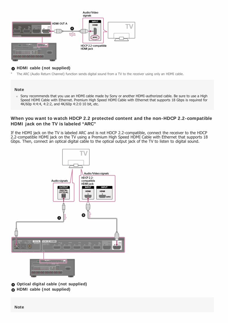
HDMI cable (not supplied)
NoteSony recommends that you use an HDMI cable made by Sony or another HDMI-authorized cable. Be sure to use a HighSpeed HDMI Cable with Ethernet. Premium High Speed HDMI Cable with Ethernet that supports 18 Gbps is required for4K/60p 4:4:4, 4:2:2, and 4K/60p 4:2:0 10 bit, etc.
When you want to watch HDCP 2.2 protected content and the non-HDCP 2.2-compatibleHDMI jack on the TV is labeled “ARC”
If the HDMI jack on the TV is labeled ARC and is not HDCP 2.2-compatible, connect the receiver to the HDCP2.2-compatible HDMI jack on the TV using a Premium High Speed HDMI Cable with Ethernet that supports 18Gbps. Then, connect an optical digital cable to the optical output jack of the TV to listen to digital sound.
Optical digital cable (not supplied) HDMI cable (not supplied)
Note
The ARC (Audio Return Channel) function sends digital sound from a TV to the receiver using only an HDMI cable.*
Sony recommends that you use an HDMI cable made by Sony or another HDMI-authorized cable. Be sure to use a HighSpeed HDMI Cable with Ethernet. Premium High Speed HDMI Cable with Ethernet that supports 18 Gbps is required for4K/60p 4:4:4, 4:2:2, and 4K/60p 4:2:0 10 bit, etc.
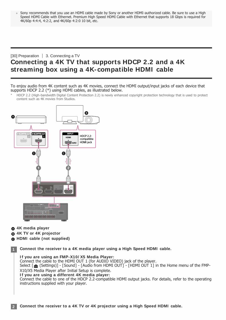
[30] Preparation 3. Connecting a TV
Connecting a 4K TV that supports HDCP 2.2 and a 4Kstreaming box using a 4K-compatible HDMI cable
To enjoy audio from 4K content such as 4K movies, connect the HDMI output/input jacks of each device thatsupports HDCP 2.2 (*) using HDMI cables, as illustrated below.
4K media player 4K TV or 4K projector HDMI cable (not supplied)
HDCP 2.2 (High-bandwidth Digital Content Protection 2.2) is newly enhanced copyright protection technology that is used to protectcontent such as 4K movies from Studios.
*
Connect the receiver to a 4K media player using a High Speed HDMI cable.
If you are using an FMP-X10/X5 Media Player:Connect the cable to the HDMI OUT 1 (for AUDIO VIDEO) jack of the player.Select [ (Settings)] - [Sound] - [Audio from HDMI OUT] - [HDMI OUT 1] in the Home menu of the FMP-X10/X5 Media Player after Initial Setup is complete.If you are using a different 4K media player:Connect the cable to one of the HDCP 2.2-compatible HDMI output jacks. For details, refer to the operatinginstructions supplied with your player.
1
Connect the receiver to a 4K TV or 4K projector using a High Speed HDMI cable.2

NoteSony recommends that you use an HDMI cable made by Sony or another HDMI-authorized cable. Be sure to use a HighSpeed HDMI Cable with Ethernet. Premium High Speed HDMI Cable with Ethernet that supports 18 Gbps is required for4K/60p 4:4:4, 4:2:2, and 4K/60p 4:2:0 10 bit, etc.
[31] Preparation 3. Connecting a TV
Notes on connecting cables
Before connecting cables, be sure to disconnect the AC power cord (mains lead).It is not necessary to connect all of the cables. Connect cables according to the availability of jacks on theconnected device.Sony recommends that you use an HDMI cable made by Sony or another HDMI-authorized cable. Be sure touse a High Speed HDMI Cable with Ethernet. Premium High Speed HDMI Cable with Ethernet that supports18 Gbps is required for 4K/60p 4:4:4, 4:2:2, and 4K/60p 4:2:0 10 bit, etc. For details about the highbandwidth video format, see “Video formats supported by the receiver.”We do not recommend using an HDMI-DVI conversion cable. If you connect an HDMI-DVI conversion cableto a DVI-D device, the sound and/or image may be lost. Connect separate audio cables or digital connectingcables, then reassign the input jacks if the sound is not output correctly.When connecting optical digital cables, insert the plugs straight until they click into place.Do not bend or tie optical digital cables.When you use high bandwidth video formats such as 4K/60p 4:4:4, 4:2:2 and 4K/60p 4:2:0 10 bit, be sureto set the HDMI signal format. For details, see “Setting HDMI signal formats (HDMI Signal Format).”
HintAll of the digital audio jacks are compatible with 32 kHz, 44.1 kHz, 48 kHz, and 96 kHz sampling frequencies.
If you want to connect several digital devices, but cannot find an unused input
In this case, reassign the input jacks.
[32] Preparation 3. Connecting a TV
About HDMI connections
High-Definition Multimedia Interface (HDMI) is an interface that transmits video and audio signals in digitalformat. Connecting devices made by Sony that are “BRAVIA” Sync-compatible makes operations simpler.
If you are using a BRAVIA TV with the series name X950B, X900B or X850B:Connect the cable to the HDMI IN 1 jack of your TV.If you are using a different 4K TV or 4K projector:Connect to one of the HDCP 2.2-compatible HDMI input jacks. If the jack is not compatible with the ARC(Audio Return Channel) function, also connect an optical digital cable. For details, refer to the operatinginstructions supplied with your 4K TV or 4K projector.
HDMI features
VideoAll HDMI jacks support ITU-R BT.2020 wide color spaces, 3D, 4K, Deep Color (Deep Colour) and HDR (HighDynamic Range) contents pass-through.BT.2020 color space is new wider color standard that is defined for ultra-high definition television systems.HDR is an emerging video format that can display a wider range of brightness levels.To enjoy 3D content, connect a 3D-compatible TV and video device (Blu-ray Disc Player, Blu-ray Discrecorder, PlayStation 4, etc.) to the receiver using High Speed HDMI Cables with Ethernet, put on 3Dglasses, and then play 3D-compatible content.To enjoy 4K content, connect a 4K-compatible TV or video device (Blu-ray Disc Player, etc.) to the receiverusing Premium High Speed HDMI Cables with Ethernet that support 18 Gbps, and then play 4K-compatiblecontent.Premium High Speed HDMI Cable with Ethernet that supports 18 Gbps is required for 4K/60p 4:4:4, 4:2:2,and 4K/60p 4:2:0 10 bit, etc.The HDMI IN 1, 2, 3, 4, and 5 jacks support bandwidths of up to 18 Gbps when [HDMI Signal Format] in the[HDMI Setup] menu is set to [Enhanced format], and bandwidths of up to 9 Gbps when [HDMI SignalFormat] in the [HDMI Setup] menu is set to [Standard format].The HDMI IN 6 (GAME) jack (STR-ZA3100ES/STR-ZA2100ES only) supports bandwidths of up to 9 Gbps.The HDMI OUT A jack supports bandwidths of up to 18 Gbps.The HDMI OUT B jack supports bandwidths of up to 18 Gbps when [HDMI Out B Mode] in the [HDMI Setup]menu is set to [Main], and bandwidths of up to 9 Gbps when [HDMI Out B Mode] in the [HDMI Setup] menuis set to [Zone2].Analog video signals input to the VIDEO jack or COMPONENT VIDEO jacks can be output as HDMI signals.
AudioDigital audio signals transmitted by HDMI can be output from the SPEAKERS terminals and the PRE OUTjacks on this receiver. This signal supports Dolby Audio, DTS, DSD, and Linear PCM.This receiver supports High Bitrate Audio (DTS-HD Master Audio, Dolby TrueHD, DTS:X Master Audio, DolbyAtmos).The receiver can receive Multi Channel Linear PCM (up to 8 channels) with a sampling frequency of 192 kHzor less via an HDMI connection.Audio signals input to the OPTICAL IN, COAXIAL IN and ANALOG IN jacks can be output as HDMI signalswith converted analog video signals from the HDMI OUT B (ZONE 2) jack when [HDMI Out B Mode] is set to[Zone2].The HDMI OUT A jack supports Audio Return Channel (ARC).
HDCPAll HDMI jacks on the receiver support High-bandwidth Digital Content Protection System Revision 2.2 (HDCP2.2). Connect these HDMI jacks to jacks that support HDCP 2.2 on the TV and AV device. Refer to theoperating instructions of the connected device for details.HDCP 2.2 is newly enhanced copyright protection technology that is used to protect content such as 4Kmovies.
NoteDepending on the TV or video device, 4K or 3D content may not be displayed. Check the HDMI video formats supportedby the receiver.
Refer to the operating instructions of each connected device for details.
[33] Preparation 4. Connecting audio-visual devices and the antennas (aerials)
Connecting devices with HDMI jacks
Connect devices to the receiver as illustrated below.Before connecting cables, be sure to disconnect the AC power cord (mains lead).

All HDMI jacks on the receiver support High-bandwidth Digital Content Protection System Revision 2.2 (HDCP2.2). To watch content protected by HDCP 2.2, such as 4K content, connect these HDMI jacks to jacks thatsupport HDCP 2.2 on the TV and AV device. Refer to the operating instructions of the connected device fordetails.
Rear (for STR-ZA3100ES/STR-ZA2100ES)
Rear (for STR-ZA1100ES)
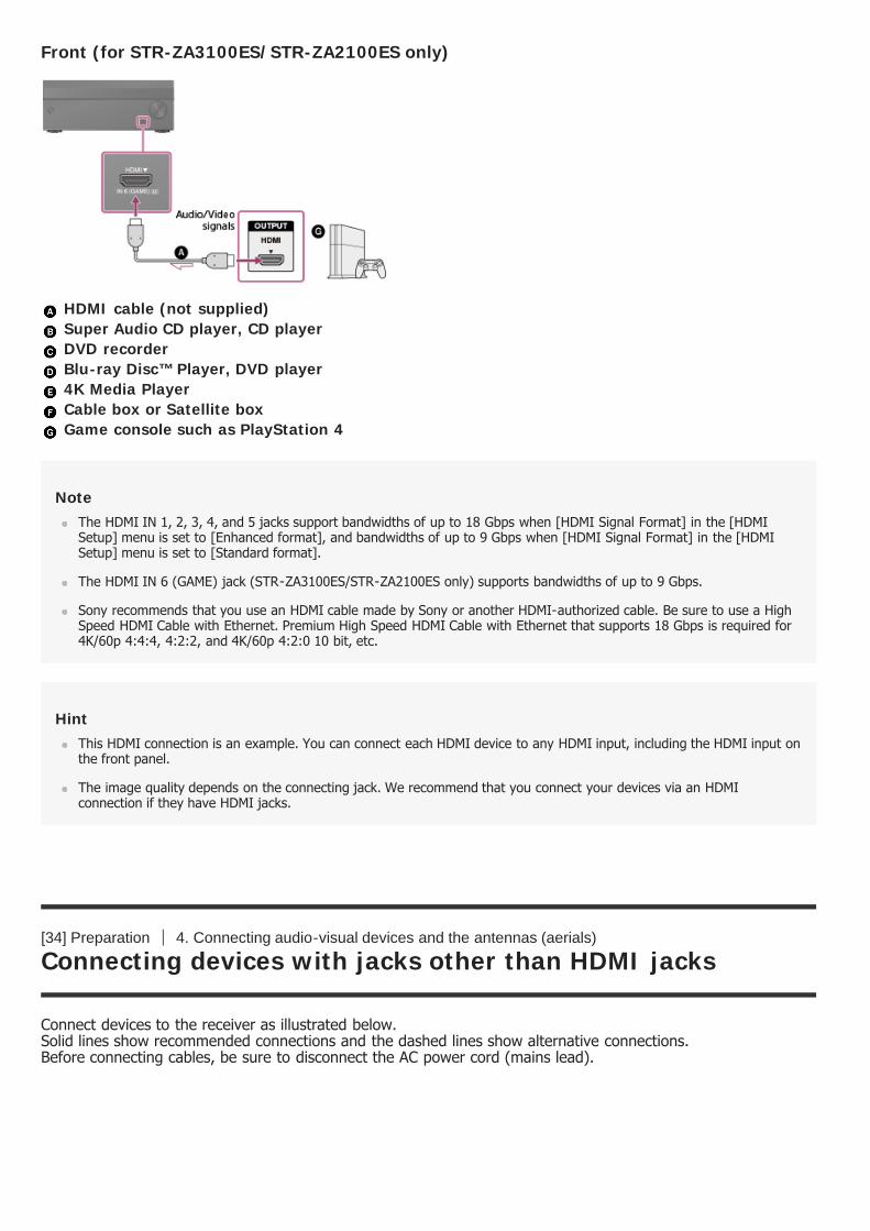
Front (for STR-ZA3100ES/STR-ZA2100ES only)
HDMI cable (not supplied) Super Audio CD player, CD player DVD recorder Blu-ray Disc™ Player, DVD player 4K Media Player Cable box or Satellite box Game console such as PlayStation 4
NoteThe HDMI IN 1, 2, 3, 4, and 5 jacks support bandwidths of up to 18 Gbps when [HDMI Signal Format] in the [HDMISetup] menu is set to [Enhanced format], and bandwidths of up to 9 Gbps when [HDMI Signal Format] in the [HDMISetup] menu is set to [Standard format].
The HDMI IN 6 (GAME) jack (STR-ZA3100ES/STR-ZA2100ES only) supports bandwidths of up to 9 Gbps.
Sony recommends that you use an HDMI cable made by Sony or another HDMI-authorized cable. Be sure to use a HighSpeed HDMI Cable with Ethernet. Premium High Speed HDMI Cable with Ethernet that supports 18 Gbps is required for4K/60p 4:4:4, 4:2:2, and 4K/60p 4:2:0 10 bit, etc.
HintThis HDMI connection is an example. You can connect each HDMI device to any HDMI input, including the HDMI input onthe front panel.
The image quality depends on the connecting jack. We recommend that you connect your devices via an HDMIconnection if they have HDMI jacks.
[34] Preparation 4. Connecting audio-visual devices and the antennas (aerials)
Connecting devices with jacks other than HDMI jacks
Connect devices to the receiver as illustrated below.Solid lines show recommended connections and the dashed lines show alternative connections.Before connecting cables, be sure to disconnect the AC power cord (mains lead).

Audio cable (not supplied) Video cable (not supplied) Component video cable (not supplied) Optical digital cable (not supplied) Coaxial digital cable (not supplied)
HintYou can rename each input so that the name can be displayed on the display panel of the receiver. For details, see“Changing the name for each input (Name).”
The image quality depends on the connecting jack. We recommend that you connect your devices via an HDMIconnection if they have HDMI jacks.
[35] Preparation 4. Connecting audio-visual devices and the antennas (aerials)
Connecting the antennas (aerials)
If you connect devices with an OPTICAL jack, reassign the input jacks. For details, see “Using other video/audio input jacks (InputAssignment).”
*
Connect the supplied antennas (aerials) to the receiver as illustrated below.Before connecting antenna (aerial), be sure to disconnect the AC power cord (mains lead).
AM loop antenna (aerial) (supplied) FM wire antenna (aerial) (supplied)
NoteTo prevent noise pickup, keep the AM loop antenna (aerial) away from the receiver and other devices.
Be sure to fully extend the FM wire antenna (aerial).
After connecting the FM wire antenna (aerial), keep it as horizontal as possible.
[36] Preparation 4. Connecting audio-visual devices and the antennas (aerials)
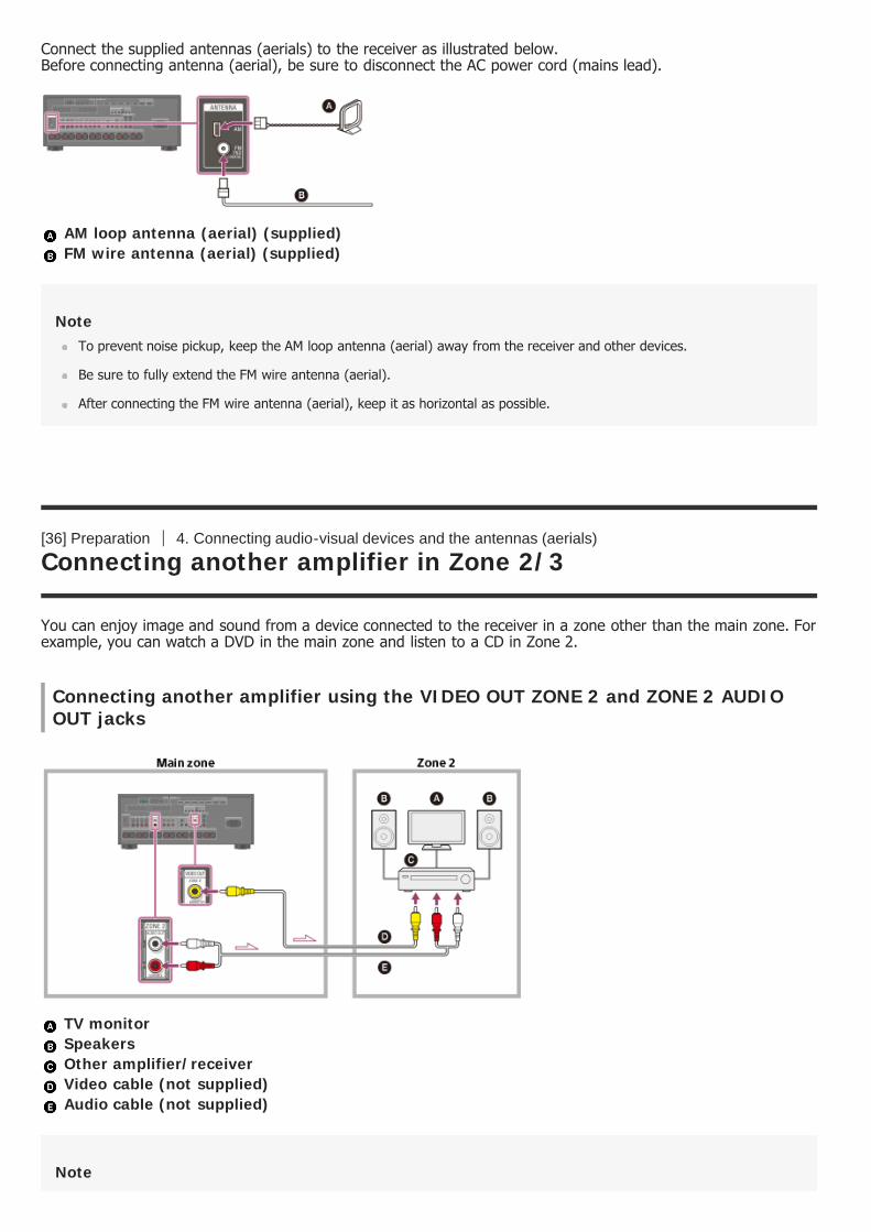
Connecting another amplifier in Zone 2/3
You can enjoy image and sound from a device connected to the receiver in a zone other than the main zone. Forexample, you can watch a DVD in the main zone and listen to a CD in Zone 2.
Connecting another amplifier using the VIDEO OUT ZONE 2 and ZONE 2 AUDIOOUT jacks
TV monitor Speakers Other amplifier/receiver Video cable (not supplied) Audio cable (not supplied)
Note
The VIDEO OUT ZONE2 jack can output video signal input from the VIDEO IN jacks.
When outputting optical/coaxial audio signals, set the audio output to PCM on the connected device. For details, refer tothe operating instructions of the connected device.
Connecting another amplifier or TV in Zone 2 (with HDMI connection)
HDMI video/audio input signals, optical/coaxial audio input signals are output to Zone 2 using the HDMI OUT B(ZONE 2) jack on the receiver.
Speakers TV Other amplifier/receiver HDMI cable (not supplied)
NoteThe following settings are required for this connection.
Set [HDMI Out B Mode] in the [HDMI Setup] menu to [Zone2]Set [Zone2 Audio Out] in the [HDMI Setup] menu to [Zone2 AMP]
When outputting optical/coaxial audio signals, set the audio output to PCM on the connected device. For details, refer tothe operating instructions of the connected device.
Connecting another amplifier using the ZONE 3 AUDIO OUT jacks
Speakers Other amplifier/receiver Audio cable (not supplied)

NoteOnly devices connected to the analog audio input jacks and the built-in tuner (FM/AM) can output signals to Zone 3. Nosignals are output from devices connected to only the digital input jacks.
[37] Preparation 4. Connecting audio-visual devices and the antennas (aerials)
Digital audio formats supported by the receiver
The digital audio formats that this receiver can decode depend on the digital audio output jacks of the connecteddevice. This receiver supports the following audio formats. The words in brackets are those indicated on thedisplay panel.
Digital audio format
Maximum number of decodedchannels Connection with
the receiverSTR-ZA3100ES/STR-ZA2100ES
STR-ZA1100ES
Dolby Digital [DOLBY DIGITAL] 5.1 5.1 COAXIAL/OPTICAL,HDMI
Dolby Digital Plus [DOLBY DIGITAL +](*1) 7.1 7.1 HDMI
Dolby TrueHD [DOLBY TrueHD] (*1) 7.1 7.1 HDMI
Dolby Atmos - Dolby Digital Plus[ATMOS - DD+] (*1) (*2) 5.1.4 or 7.1.2 5.1.2 or
7.1 HDMI
Dolby Atmos - Dolby TrueHD [ATMOS -TrueHD] (*1) (*2) 5.1.4 or 7.1.2 5.1.2 or
7.1 HDMI
DTS [DTS] 5.1 5.1 COAXIAL/OPTICAL,HDMI
DTS-ES Discrete [DTS-ES Dscrt] 6.1 6.1 COAXIAL/OPTICAL,HDMI
DTS-ES Matrix [DTS-ES Mtrx] 6.1 6.1 COAXIAL/OPTICAL,HDMI
DTS 96/24 [DTS 96/24] 5.1 5.1 COAXIAL/OPTICAL,HDMI
DTS-HD High Resolution Audio [DTS-HD HI RES] (*1) 7.1 7.1 HDMI
DTS-HD Master Audio [DTS-HD MA](*1) 7.1 7.1 HDMI
DTS:X [DTS:X] (*1) 5.1.4 or 7.1.2 5.1.2 or7.1 HDMI
DTS:X Master Audio [DTS:X MA] (*1) 5.1.4 or 7.1.2 5.1.2 or7.1 HDMI
DSD [DSD] (*1) 5.1 5.1 HDMI
Multi Channel Linear PCM [LINEARPCM] (*1) 7.1 7.1 HDMI

[38] Preparation 4. Connecting audio-visual devices and the antennas (aerials)
Video formats supported by the receiver
Audio signals are output in another format if the playback device does not correspond to the actual format. For details, refer to theoperating instructions of the playback device.
*1
Dolby Atmos is decoded as Dolby Digital Plus or Dolby TrueHD if the speaker pattern is set to 2.0, 2.1, 3.0, 3.1, 4.0, 4.1, 5.0 or 5.1.*2
Video format 2D3D
Framepacking
Side-by-Side(Half)
Over-Under (Top-and-Bottom)
4096 × 2160p @ 59.94/60Hz
○(*1) - - -
4096 × 2160p @ 50 Hz ○(*1) - - -
4096 × 2160p @ 29.97/30Hz
○(*2) - - -
4096 × 2160p @ 25 Hz ○(*2) - - -
4096 × 2160p @ 23.98/24Hz
○(*2) - - -
3840 × 2160p @ 59.94/60Hz
○(*1) - - -
3840 × 2160p @ 50 Hz ○(*1) - - -
3840 × 2160p @ 29.97/30Hz
○(*2) - - -
3840 × 2160p @ 25 Hz ○(*2) - - -
3840 × 2160p @ 23.98/24Hz
○(*2) - - -
1920 × 1080p @ 59.94/60Hz ○ - ○ ○
1920 × 1080p @ 50 Hz ○ - ○ ○
1920 × 1080p @ 29.97/30Hz ○ ○ ○ ○
1920 × 1080p @ 25 Hz ○ ○ ○ ○
1920 × 1080p @ 23.98/24Hz ○ ○ ○ ○
1920 × 1080i @ 59.94/60Hz ○ ○ ○ ○
1920 × 1080i @ 50 Hz ○ ○ ○ ○

[39] Preparation 4. Connecting audio-visual devices and the antennas (aerials)
Notes on connecting cables
Before connecting cables, be sure to disconnect the AC power cord (mains lead).It is not necessary to connect all of the cables. Connect cables according to the availability of jacks on theconnected device.Sony recommends that you use an HDMI cable made by Sony or another HDMI-authorized cable. Be sure touse a High Speed HDMI Cable with Ethernet. Premium High Speed HDMI Cable with Ethernet that supports18 Gbps is required for 4K/60p 4:4:4, 4:2:2, and 4K/60p 4:2:0 10 bit, etc. For details about the highbandwidth video format, see “Video formats supported by the receiver.”We do not recommend using an HDMI-DVI conversion cable. If you connect an HDMI-DVI conversion cableto a DVI-D device, the sound and/or image may be lost. Connect separate audio cables or digital connectingcables, then reassign the input jacks if the sound is not output correctly.When connecting optical digital cables, insert the plugs straight until they click into place.Do not bend or tie optical digital cables.When you use high bandwidth video formats such as 4K/60p 4:4:4, 4:2:2 and 4K/60p 4:2:0 10 bit, be sureto set the HDMI signal format. For details, see “Setting HDMI signal formats (HDMI Signal Format).”
HintAll of the digital audio jacks are compatible with 32 kHz, 44.1 kHz, 48 kHz, and 96 kHz sampling frequencies.
If you want to connect several digital devices, but cannot find an unused input
In this case, reassign the input jacks.
[40] Preparation 4. Connecting audio-visual devices and the antennas (aerials)
About HDMI connections
1280 × 720p @ 59.94/60Hz ○ ○ ○ ○
1280 × 720p @ 50 Hz ○ ○ ○ ○
1280 × 720p @ 29.97/30Hz ○ ○ ○ ○
1280 × 720p @ 23.98/24Hz ○ ○ ○ ○
720 × 480p @ 59.94/60 Hz ○ - - -
720 × 576p @ 50 Hz ○ - - -
640 × 480p @ 59.94/60 Hz ○ - - -
If you use YCbCr 4:4:4/YCbCr 4:2:2/RGB 4:4:4 or YCbCr 4:2:0 deep color (10 bit or 12 bit) of these video formats, be sure to useHDMI IN 1, 2, 3, 4 and/or 5 jacks, and Premium High Speed HDMI Cables, which can support bandwidth up to 18 Gbps.
*1
If you use deep color (10 bit or 12 bit) of these video formats, be sure to use HDMI IN 1, 2, 3, 4 and/or 5 jacks, and Premium HighSpeed HDMI Cables, which can support bandwidth up to 18 Gbps.
*2

High-Definition Multimedia Interface (HDMI) is an interface that transmits video and audio signals in digitalformat. Connecting devices made by Sony that are “BRAVIA” Sync-compatible makes operations simpler.
HDMI features
VideoAll HDMI jacks support ITU-R BT.2020 wide color spaces, 3D, 4K, Deep Color (Deep Colour) and HDR (HighDynamic Range) contents pass-through.BT.2020 color space is new wider color standard that is defined for ultra-high definition television systems.HDR is an emerging video format that can display a wider range of brightness levels.To enjoy 3D content, connect a 3D-compatible TV and video device (Blu-ray Disc Player, Blu-ray Discrecorder, PlayStation 4, etc.) to the receiver using High Speed HDMI Cables with Ethernet, put on 3Dglasses, and then play 3D-compatible content.To enjoy 4K content, connect a 4K-compatible TV or video device (Blu-ray Disc Player, etc.) to the receiverusing Premium High Speed HDMI Cables with Ethernet that support 18 Gbps, and then play 4K-compatiblecontent.Premium High Speed HDMI Cable with Ethernet that supports 18 Gbps is required for 4K/60p 4:4:4, 4:2:2,and 4K/60p 4:2:0 10 bit, etc.The HDMI IN 1, 2, 3, 4, and 5 jacks support bandwidths of up to 18 Gbps when [HDMI Signal Format] in the[HDMI Setup] menu is set to [Enhanced format], and bandwidths of up to 9 Gbps when [HDMI SignalFormat] in the [HDMI Setup] menu is set to [Standard format].The HDMI IN 6 (GAME) jack (STR-ZA3100ES/STR-ZA2100ES only) supports bandwidths of up to 9 Gbps.The HDMI OUT A jack supports bandwidths of up to 18 Gbps.The HDMI OUT B jack supports bandwidths of up to 18 Gbps when [HDMI Out B Mode] in the [HDMI Setup]menu is set to [Main], and bandwidths of up to 9 Gbps when [HDMI Out B Mode] in the [HDMI Setup] menuis set to [Zone2].Analog video signals input to the VIDEO jack or COMPONENT VIDEO jacks can be output as HDMI signals.
AudioDigital audio signals transmitted by HDMI can be output from the SPEAKERS terminals and the PRE OUTjacks on this receiver. This signal supports Dolby Audio, DTS, DSD, and Linear PCM.This receiver supports High Bitrate Audio (DTS-HD Master Audio, Dolby TrueHD, DTS:X Master Audio, DolbyAtmos).The receiver can receive Multi Channel Linear PCM (up to 8 channels) with a sampling frequency of 192 kHzor less via an HDMI connection.Audio signals input to the OPTICAL IN, COAXIAL IN and ANALOG IN jacks can be output as HDMI signalswith converted analog video signals from the HDMI OUT B (ZONE 2) jack when [HDMI Out B Mode] is set to[Zone2].The HDMI OUT A jack supports Audio Return Channel (ARC).
HDCPAll HDMI jacks on the receiver support High-bandwidth Digital Content Protection System Revision 2.2 (HDCP2.2). Connect these HDMI jacks to jacks that support HDCP 2.2 on the TV and AV device. Refer to theoperating instructions of the connected device for details.HDCP 2.2 is newly enhanced copyright protection technology that is used to protect content such as 4Kmovies.
NoteDepending on the TV or video device, 4K or 3D content may not be displayed. Check the HDMI video formats supportedby the receiver.
Refer to the operating instructions of each connected device for details.
[41] Preparation 5. Connecting to the network
System requirements for a wired LAN connection
The following system environment is required to use the network function of the receiver via a wired LANconnection.
RouterUse a router compatible with transmission speeds of 100 Mbps or greater.We recommend that you use a router equipped with a built-in DHCP (Dynamic Host Configuration Protocol)server because the default setting on the receiver is DHCP. This function automatically assigns IP addresses to devices on the LAN.
LAN cableWe recommend using a normal shielded type cable for a wired LAN to avoid electric noise.Some flat-type LAN cables are easily affected by noise.We recommend using a Category 7 cable.
[42] Preparation 5. Connecting to the network
Connecting the receiver to the network using LAN cables (forSTR-ZA3100ES)
The following illustration is an example configuration of a home network with the receiver, and a computer.
Computer LAN cable (not supplied) Wireless access point, etc. Network camera, etc. Router Modem Internet
NoteConnect a router to one among ports 1 to 8 of the receiver using only one LAN cable. Do not connect the same router tothe receiver using more than one LAN cable. It may cause a malfunction.
Ports No. 1 and No. 2 support PoE (Power over Ethernet, Alternative A). If you connect a PoE-compatible device to oneof these ports, power will be supplied to the device from the receiver.
You can also connect a device that does not support PoE to the PoE port.
The PoE port lights in red while supplying power.
This receiver supports PoE Class 3.
[43] Preparation 5. Connecting to the network
Connecting the receiver to the network using LAN cables (forSTR-ZA2100ES/STR-ZA1100ES)
The following illustration is an example configuration of a home network with the receiver, and a computer. The STR-ZA2100ES is used for illustrative purpose in this topic.
Computer LAN cable (not supplied) Router Modem Internet
[44] Preparation 6. Turning on the receiver/preparing the remote control
Inserting batteries into the remote control
Insert two R03 (size AAA) batteries (supplied) into the remote control. Make sure that the + and - ends are inthe correct position when installing batteries.

NoteDo not leave the remote control in an extremely hot or humid place.
Do not use a new battery with an old one.
Do not mix manganese batteries with other kinds of batteries.
Do not expose the remote control sensor to direct sunlight or lights. Doing so may cause a malfunction.
If you do not intend to use the remote control for an extended period of time, remove the batteries to avoid possibledamage from battery leakage and corrosion.
When the receiver no longer responds to the remote control, replace both of the batteries with new ones.
[45] Preparation 6. Turning on the receiver/preparing the remote control
Turning on the receiver
Before connecting the AC power cord (mains lead), be sure to make connections with speakers and the otherdevices.
Connect the supplied AC power cord (mains lead) to the AC IN terminal on the receiver firmly,then connect the AC power cord (mains lead) to a wall outlet.
AC IN terminal AC power cord (mains lead) (supplied)
1
Space remains between the plug and the rear panel even when the power cord (mains lead) is inserted firmly. The cord issupposed to be connected this way. This is not malfunction.
*
Press (power) to turn on the receiver.
2
NoteAfter you turn off the receiver, [STANDBY] flashes on the display panel. Do not disconnect the AC power cord (mainslead) while [STANDBY] is flashing. This may cause a malfunction.
[46] Preparation 6. Turning on the receiver/preparing the remote control
Notes on installing the receiver
Do not install the receiver in a confined space, such as a bookcase.Sufficient space around the receiver is needed to release heat. When placing the receiver in a rack, leavemore than 44.45 mm (1.75 in) space above the receiver, and more than 44.45 mm (1.75 in) space along thesides of the receiver. The rack behind the receiver should be open. If you place the receiver with its backagainst the wall, leave more than 88.9 mm (3.5 in) space between the receiver and the wall.Make sure to use a “WS-RE1” dedicated rack mount kit for this receiver when mounting the receiver on arack mount.Place the receiver in a location with adequate ventilation to prevent heat buildup and prolong the life of thereceiver.Do not place the receiver near heat sources, or in a place subject to direct sunlight, excessive dust, ormechanical shock.Do not place anything on top of the cabinet that might block the ventilation holes and cause malfunctions.Magnets are attached to both the front panel and front cover. Do not place cards with magnetic stripes, suchas bank cards or ID passes, near the receiver. These cards may become unusable due to the effects of themagnets on the receiver.
[47] Preparation 7. Setting up the receiver using Easy Setup
Setting up the receiver using the Easy Setup
When you turn on the receiver for the first time or after the receiver is initialized, the Easy Setup screen appearson the TV screen. You can set up the following settings for the receiver by following the instructions on the EasySetup screen.
Auto Calibration
Check your speaker system and perform automatic calibration according to the configuration andarrangement of your speaker system.
Internet Setup
Configure settings to connect the receiver to the network.
NoteSwitch the input of the TV to the input to which the receiver is connected to use this function.
You can also turn on the receiver using MAIN (power) on the remote control. To turn off the receiver,press MAIN (power) again.

If the Easy Setup screen does not appear or you want to display the Easy Setup screen manually, you candisplay it by selecting [Setup] - [Easy Setup] from the home menu.
[48] Preparation Performing Auto Calibration
1. About Auto Calibration
Auto Calibration allows you to perform automatic calibration as follows.
Check the connection between each speaker and the receiver.Adjust the speaker level.Measure the distance of each speaker from your seating position. (*1)Measure the speaker size. (*1)Measure the frequency characteristics (EQ). (*1)Measure the frequency characteristics (Phase). (*1) (*2)
NoteThe D.C.A.C. is designed to achieve proper sound balance for your room. However, you can adjust the speaker levelsmanually according to your preference using [Test Tone].
[49] Preparation Performing Auto Calibration
2. Before you perform Auto Calibration
Before you perform Auto Calibration, check the following items:
Set up and connect the speakers.Do not connect any microphones other than the supplied calibration microphone to the CALIBRATION MICjack.If using a bi-amplifier connection or speakers with a front B connection, set the assignment for theSPEAKERS SURROUND BACK/HEIGHT (FRONT B/BI-AMP/ZONE 2) terminals properly. For details, see“Assigning the surround back speaker terminals (SB Speaker Assign).”Set the speaker output to a setting other than [SPEAKERS OFF]. For details, see “4. Selecting the frontspeakers.”Remove any obstructions between the calibration microphone and the speakers.For accurate measurement, make sure the environment is quiet and free from noise.
NoteThe speakers emit very loud sound during the calibration and the volume cannot be adjusted. Be considerate of yourneighbors and any children who are present.
If the muting function has been activated before you perform Auto Calibration, the muting function will shut offautomatically.
It may not be possible to take the correct measurements or to perform Auto Calibration at all if special speakers such asdipole speakers are used.
The measurement result is not utilized when [Direct] is being used and an analog input is selected.*1The measurement result may be not utilized, depending on the audio formats.*2
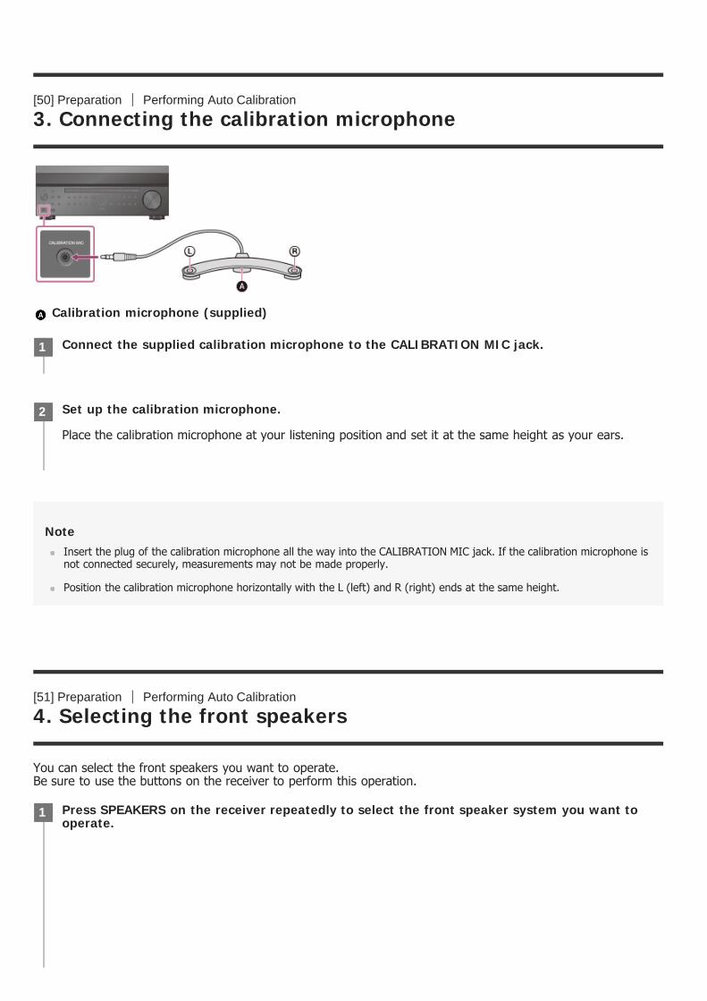
[50] Preparation Performing Auto Calibration
3. Connecting the calibration microphone
Calibration microphone (supplied)
NoteInsert the plug of the calibration microphone all the way into the CALIBRATION MIC jack. If the calibration microphone isnot connected securely, measurements may not be made properly.
Position the calibration microphone horizontally with the L (left) and R (right) ends at the same height.
[51] Preparation Performing Auto Calibration
4. Selecting the front speakers
You can select the front speakers you want to operate. Be sure to use the buttons on the receiver to perform this operation.
Connect the supplied calibration microphone to the CALIBRATION MIC jack.1
Set up the calibration microphone.
Place the calibration microphone at your listening position and set it at the same height as your ears.
2
Press SPEAKERS on the receiver repeatedly to select the front speaker system you want tooperate.
1

The indicators on the display panel shows which set of terminals are selected.
SP A : Speakers connected to the SPEAKERS FRONT A terminals.SP B (*):Speakers connected to the SPEAKERS SURROUND BACK/HEIGHT (FRONT B/BI-AMP/ZONE 2) terminals.SP AB (*):Speakers connected to both the SPEAKERS FRONT A and SPEAKERS SURROUND BACK/HEIGHT (FRONTB/BI-AMP/ZONE 2) terminals (parallel connection).(None): [SPEAKERS OFF] appears on the display panel. No audio signals are output from any speaker terminals, orthe PRE OUT jacks.
[52] Preparation Performing Auto Calibration
5. Performing Auto Calibration
You can perform automatic calibration from your listening position.
To select [SP B] or [SP AB], set the assignment for the SPEAKERS SURROUND BACK/HEIGHT (FRONT B/BI-AMP/ZONE 2) terminals to[Front B] by using [SB Speaker Assign] in the [Speaker Setup] menu.
*
Select [Setup] - [Speaker Setup] from the home menu.1
Select [Auto Calibration].2
Follow the instructions on the TV screen, then press to select [Start].
The measurement starts in 5 seconds. The measurement process will take approximately 30 seconds with a test tone.When the measurement ends, a beep sounds and the screen switches.
3
Select the item you want.
Save: Saves the measurement results and exits the setting process.Retry: Performs the Auto Calibration again.Discard: Exits the setting process without saving the measurement results.
4

Calibration Matching
When Auto Calibration is executed, this function works automatically, matching the distance and level of theright and left speakers. You can set this function only after the D.C.A.C. measurement process has beencompleted and the results of the D.C.A.C. measurement are saved. The setting is valid until you change it.
NoteIf an error code or warning message appears on the screen in step 3, see “List of messages after Auto Calibrationmeasurements.”
HintYou can also perform automatic calibration by pressing the AUTO CAL button on the remote control. If you use the AUTOCAL button, the following restrictions apply to the operation:
Prior settings relating to the Auto Calibration will be skipped.You can only use the display panel for the operation.
The Auto Calibration function will be canceled if you perform the following during the measurement process:Turn the receiver on or off.Press the input buttons on the remote control or on the receiver.Press .Press SPEAKERS on the receiver.Press HDMI OUTPUT.Press AMP MENU.Press HOME.Press AUTO CAL.Change the volume level.
[53] Preparation Performing Auto Calibration
6. Checking Auto Calibration results
To check error codes or warning messages received in [Auto Calibration], proceed with the following steps:
If an error code appears
Check the error and perform Auto Calibration again.
For details on the measurement results, see “6. Checking Auto Calibration results.”
Save the measurement results.
Select [Save] in step 4.
5
Select [Retry].1
Follow the instructions on the TV screen and then press to select [Start].2
If a warning message appears
Check the warning message and select [OK]. For details on the warning messages, see “List of messages afterAuto Calibration measurements.”
HintThe measurement results may vary depending on the position of the subwoofer. However, continuing to use the receiverwith that value does not cause problems.
[54] Enjoying Video and Sound Playing AV devices
Using the menu on the TV screen
You can display the menu of the receiver on the TV screen (*).
The measurement starts in 5 seconds. The measurement process will take approximately 30 seconds with a test tone.When the measurement ends, a beep sounds and the screen switches.
Select the item you want.
Save: Saves the measurement results and exits the setting process.Retry: Performs the Auto Calibration again.Discard: Exits the setting process without saving the measurement results.
3
Save the measurement results.
Select [Save] in step 3.
4
When you want to display the menu on the TV screen connected to the HDMI OUT B (ZONE 2) jack, set [HDMI Out B Mode] to[Main].
*
Switch the input of the TV to the input to which the receiver is connected.1
Press HOME to display the home menu on the TV screen.2

Home menu items
Watch: Select to display video from the connected device.Listen: Select to listen to sound from the connected device.Custom Preset: Select to save various settings for the receiver and recall those settings.Sound Effects: Select to enjoy sound effects.Zone Controls: Select to adjust settings for Zone 2 or Zone 3.Setup: Select to adjust the various settings for the receiver.
NoteSound is not output from the TV speakers while the home menu is displayed.
HintWhen [OPTIONS] appears in the lower right portion of the TV screen, you can display the function list by pressingOPTIONS and selecting a related function.
To return to the previous screen, press RETURN.
To exit the menu, press HOME to display the home menu, then press HOME again.
[55] Enjoying Video and Sound Playing AV devices
Enjoying video/sound from the connected device
Press / repeatedly to select the menu you want, then press to enter the menu.3
Switch the input of the TV to the input to which the receiver is connected.1
Press HOME.
The home menu is displayed on the TV screen.Depending on the TV, the home menu may take some time to appear on the TV screen.
2
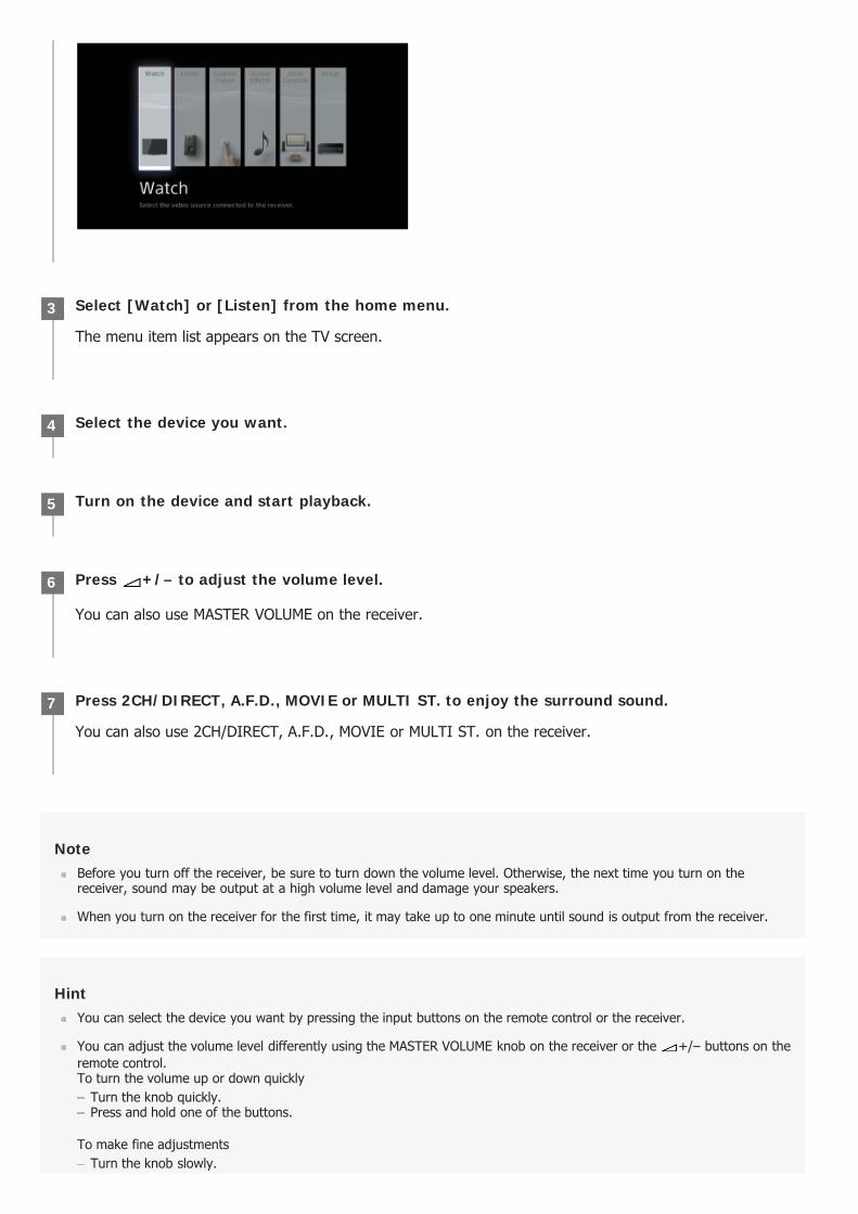
NoteBefore you turn off the receiver, be sure to turn down the volume level. Otherwise, the next time you turn on thereceiver, sound may be output at a high volume level and damage your speakers.
When you turn on the receiver for the first time, it may take up to one minute until sound is output from the receiver.
HintYou can select the device you want by pressing the input buttons on the remote control or the receiver.
You can adjust the volume level differently using the MASTER VOLUME knob on the receiver or the +/– buttons on theremote control.To turn the volume up or down quickly
Turn the knob quickly.Press and hold one of the buttons.
To make fine adjustmentsTurn the knob slowly.
Select [Watch] or [Listen] from the home menu.
The menu item list appears on the TV screen.
3
Select the device you want.4
Turn on the device and start playback.5
Press +/– to adjust the volume level.
You can also use MASTER VOLUME on the receiver.
6
Press 2CH/DIRECT, A.F.D., MOVIE or MULTI ST. to enjoy the surround sound.
You can also use 2CH/DIRECT, A.F.D., MOVIE or MULTI ST. on the receiver.
7
Press one of the buttons and release it immediately.
[56] Enjoying Video and Sound Playing AV devices
Enjoying sound of an ARC compatible TV (Audio ReturnChannel)
If your TV supports the Audio Return Channel (ARC) function, set the receiver by the following procedure tooutput the sound of the TV from the speakers connected to the receiver.
If you connect to a TV that is not compatible with the Audio Return Channel (ARC)function or you want to select an audio signal using a cable other than an HDMI cable(e.g. via an optical digital cable or an audio cable)
Select [Setup] - [Input Setup] - [Input Mode] and switch the audio input mode.
NoteBe sure to turn off the volume of the TV or activate the muting function of the TV.
If your TV does not support the System Audio Control function, set [Audio Out] to [TV + AMP] in the [HDMI Setup]menu to output the sound of the TV from the TV speaker and the speakers connected to the receiver.
[57] Enjoying Video and Sound Playing AV devices
If you use a TV compatible with Dolby Digital Plus output
The receiver can receive Dolby Atmos signals in the Dolby Digital Plus format, not only when audio signals areinput from the HDMI input jack but also from a TV connected to the receiver by using the Audio Return Channel(ARC) function.Turn on the ARC function to enable the transmission of Dolby Digital Plus signals. This receiver is designed toactivate the ARC function separately even if [Control for HDMI] is set to [Off] in the [HDMI Setup] menu. In this
Select [Setup] - [HDMI Setup] from the home menu.1
Select [Audio Return Channel].2
Select the setting you want.
Standard: The sound of the TV connected to the receiver via the HDMI OUT A jack is output from thereceiver when TV input is selected.Off: The sound of the TV connected to the receiver via the HDMI OUT A jack is not output from thereceiver even when TV input is selected.
3

case, set the receiver by the following procedure.
NoteThe ARC function only works on the TV connected to the HDMI OUT A jack.
If the Control for HDMI function is activated on the source devices connected to the receiver or the TV, the interlockingfunctions only work between the TV and the source devices.
[58] Enjoying Video and Sound Playing AV devices
Watching HDCP 2.2 copyright-protected content
To watch HDCP 2.2 copyright-protected content such as 4K content, connect the receiver and TV via an HDCP2.2-compatible HDMI jack. You can only view copyright-protected 4K content through the HDCP 2.2-compatibleHDMI jack connection. For details on whether the TV and 4K devices are equipped with an HDCP 2.2-compatibleHDMI jack, refer to the operating instructions of the TV and 4K devices.
Turn on the Control for HDMI function of the TV.1
Change the setting for the audio output of the TV so that the TV can output the Dolby DigitalPlus signals.
For details on setting the TV, refer to the operating instructions of the TV.
2
Set [Audio Return Channel] to [Standard] in the [HDMI Setup] menu on the receiver.3
Set the HDMI OUTPUT setting to [HDMI OUT A] on the receiver.4
Turn off the Control for HDMI function for all devices connected to the receiver except the TV.
For details, refer to the operating instructions of the connected devices.
5
Turn off any settings for the operation of other devices on the TV’s remote control.
For details on setting the TV, refer to the operating instructions of the TV.
6
Switch the input of the receiver to [TV].7
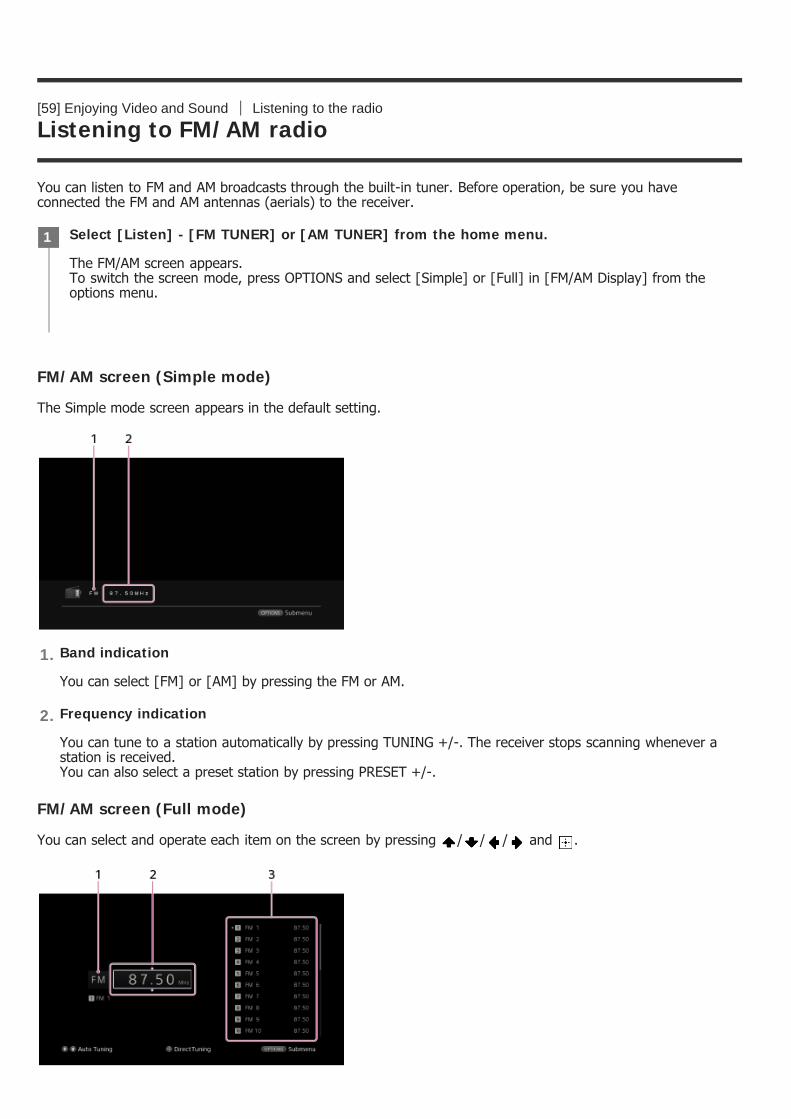
[59] Enjoying Video and Sound Listening to the radio
Listening to FM/AM radio
You can listen to FM and AM broadcasts through the built-in tuner. Before operation, be sure you haveconnected the FM and AM antennas (aerials) to the receiver.
FM/AM screen (Simple mode)
The Simple mode screen appears in the default setting.
FM/AM screen (Full mode)
You can select and operate each item on the screen by pressing / / / and .
Select [Listen] - [FM TUNER] or [AM TUNER] from the home menu.
The FM/AM screen appears.To switch the screen mode, press OPTIONS and select [Simple] or [Full] in [FM/AM Display] from theoptions menu.
1
Band indication
You can select [FM] or [AM] by pressing the FM or AM.
1.
Frequency indication
You can tune to a station automatically by pressing TUNING +/-. The receiver stops scanning whenever astation is received.You can also select a preset station by pressing PRESET +/-.
2.

[60] Enjoying Video and Sound Listening to the radio
Presetting FM/AM radio stations (Preset Memory)
You can store up to 30 FM and 30 AM stations as your favorite stations.
Band indication
You can select [FM] or [AM] by pressing / repeatedly.
1.
Frequency indication
You can tune to a station automatically by pressing / repeatedly (Auto Tuning).Press to scan from lower to higher frequency stations or press to scan from higher to lower stations.The receiver stops scanning whenever a station is received.
2.
Preset station list
You can tune to a station by selecting the preset number from the list.
3.
Select [Listen] - [FM TUNER] or [AM TUNER] from the home menu.
If the Simple mode screen appears, switch to the Full mode screen by pressing OPTIONS and selecting[Full] in [FM/AM Display] from the options menu.
1
Tune to the station that you want to preset.2
Press OPTIONS.3
Select [Preset Memory] from the options menu.4
Select a preset number.
The station is stored as the selected preset number.
5
Repeat steps 1 to 5 to store another station.
You can store stations as follows:
AM band: AM 1 to AM 30FM band: FM 1 to FM 30
6
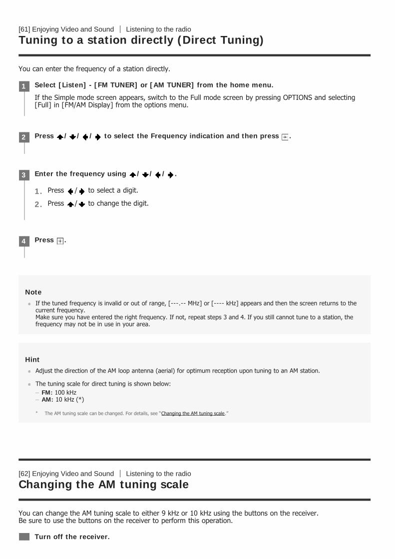
[61] Enjoying Video and Sound Listening to the radio
Tuning to a station directly (Direct Tuning)
You can enter the frequency of a station directly.
NoteIf the tuned frequency is invalid or out of range, [---.-- MHz] or [---- kHz] appears and then the screen returns to thecurrent frequency. Make sure you have entered the right frequency. If not, repeat steps 3 and 4. If you still cannot tune to a station, thefrequency may not be in use in your area.
HintAdjust the direction of the AM loop antenna (aerial) for optimum reception upon tuning to an AM station.
The tuning scale for direct tuning is shown below:FM: 100 kHzAM: 10 kHz (*)
[62] Enjoying Video and Sound Listening to the radio
Changing the AM tuning scale
You can change the AM tuning scale to either 9 kHz or 10 kHz using the buttons on the receiver. Be sure to use the buttons on the receiver to perform this operation.
Select [Listen] - [FM TUNER] or [AM TUNER] from the home menu.
If the Simple mode screen appears, switch to the Full mode screen by pressing OPTIONS and selecting[Full] in [FM/AM Display] from the options menu.
1
Press / / / to select the Frequency indication and then press .2
Enter the frequency using / / / .3
Press / to select a digit.1.Press / to change the digit.2.
Press .4
The AM tuning scale can be changed. For details, see “Changing the AM tuning scale.”*
Turn off the receiver.

NoteDepending on the settings, the receiver may take some time to change the AM tuning scale.
All preset stations will be erased when you change the tuning scale.
[63] Enjoying Video and Sound Enjoying sound effects
Selecting a sound field (Sound Field)
You can select from a variety of sound field modes according to speaker connections or input sources.
NoteThe sound fields for movie may not work, depending on the input or the speaker pattern you select, or with audioformats.
The receiver may play signals at a lower sampling frequency than the actual sampling frequency of the input signals,depending on the audio format.
Some speakers or the subwoofer may not output sound, depending on the sound field setting.
If there is any noise present, the noise may be different, depending on the sound field you select.
HintYou can also select [Sound Field] in [Sound Effects] from the home menu.
1
Hold down TUNING MODE and press (power) on the receiver.
The current AM tuning scale is changed to 9 kHz (or 10 kHz). To reset the scale to 10 kHz (or 9 kHz),repeat the procedure above.
2
Select [Setup] - [Audio Setup] from the home menu.1
Select [Sound Field].2
Select the sound field you want.
For details on each sound field, see “Selectable sound fields and their effects.”
3
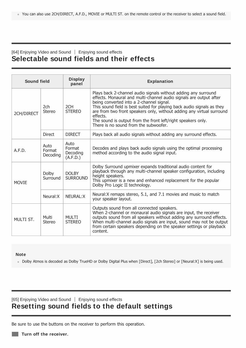
You can also use 2CH/DIRECT, A.F.D., MOVIE or MULTI ST. on the remote control or the receiver to select a sound field.
[64] Enjoying Video and Sound Enjoying sound effects
Selectable sound fields and their effects
NoteDolby Atmos is decoded as Dolby TrueHD or Dolby Digital Plus when [Direct], [2ch Stereo] or [Neural:X] is being used.
[65] Enjoying Video and Sound Enjoying sound effects
Resetting sound fields to the default settings
Be sure to use the buttons on the receiver to perform this operation.
Sound field Displaypanel Explanation
2CH/DIRECT2chStereo
2CHSTEREO
Plays back 2-channel audio signals without adding any surroundeffects. Monaural and multi-channel audio signals are output afterbeing converted into a 2-channel signal. This sound field is best suited for playing back audio signals as theyare from two front speakers only, without adding any virtual surroundeffects.The sound is output from the front left/right speakers only.There is no sound from the subwoofer.
Direct DIRECT Plays back all audio signals without adding any surround effects.
A.F.D.AutoFormatDecoding
AutoFormatDecoding(A.F.D.)
Decodes and plays back audio signals using the optimal processingmethod according to the audio signal input.
MOVIE
DolbySurround
DOLBYSURROUND
Dolby Surround upmixer expands traditional audio content forplayback through any multi-channel speaker configuration, includingheight speakers. This upmixer is a new and enhanced replacement for the popularDolby Pro Logic II technology.
Neural:X NEURAL:X Neural:X remaps stereo, 5.1, and 7.1 movies and music to matchyour speaker layout.
MULTI ST. MultiStereo
MULTISTEREO
Outputs sound from all connected speakers. When 2-channel or monaural audio signals are input, the receiveroutputs sound from all speakers without adding any surround effects. When multi-channel audio signals are input, sound may not be outputfrom certain speakers depending on the speaker settings or playbackcontent.
Turn off the receiver.

[66] Enjoying Video and Sound Enjoying sound effects
Adjusting the equalizer (Equalizer)
You can use the following parameters to adjust the tonal quality (bass/treble level) of the front, center,surround/surround back, height1 (*1), height2 (*1) and height (*2) speakers.
Level (dB) Frequency (Hz) Bass Treble
NoteThis function does not work in the following cases:
1
Hold down MULTI ST. and press (power) on the receiver.
[S.F. INITIALIZED!] appears on the display panel and all sound fields are reset to their default setting.
2
Select [Setup] - [Speaker Setup] from the home menu.1
Select [Equalizer].2
Select [Front], [Center], [Surround], [Height1] (*1), [Height2] (*1) or [Height] (*2).3
Select [Bass] or [Treble].4
Adjust the gain.5
for STR-ZA3100ES/STR-ZA2100ES*1for STR-ZA1100ES*2
[Direct] is being used and an analog input is selected.[Pure Direct] is set to [On].
Frequencies for [Bass] and [Treble] are fixed.
Depending on the audio format, the receiver may play signals at a lower sampling frequency than the original samplingfrequency of the input signals.
HintYou can also select [Equalizer] in [Sound Effects] from the home menu.
[67] Enjoying Video and Sound Enjoying sound effects
Enjoying clear and dynamic sound at a low volume (SoundOptimizer)
You can enjoy clear and dynamic sound at low volume levels using the Sound Optimizer function. After Auto Calibration is performed, the sound level is optimized to suit your environment.
NoteThis function does not work in the following cases:
[Direct] is being used and an analog input is selected.[Pure Direct] is set to [On].
The receiver may play signals at a lower sampling frequency than the actual sampling frequency of the input signals,depending on the audio format.
HintYou can also select [Sound Optimizer] in the [Audio Setup] menu.
[68] Enjoying Video and Sound Enjoying sound effects
Enjoying more natural sound with speakers installed in the
Select [Sound Effects] - [Sound Optimizer] from the home menu.1
Select the setting you want.
Normal: Adjusts for the reference level of a movie.Low: Adjusts for a CD or other software whose average sound pressure level is processed highly.Off
2

ceiling (In-Ceiling Speaker Mode)
Set whether or not to use In-Ceiling Speaker Mode with the current input. In a setup where the front and center speakers are installed in the ceiling, lowering the audio output position tothe screen height allows you to enjoy a more natural experience.
NoteThis function does not work in the following cases:
[Direct] is being used and an analog input is selected.Dolby Atmos enabled speakers are used.Dolby Atmos is being decoded.[Pure Direct] is set to [On].
This function may not work depending on the audio format.
The receiver may play signals at a lower sampling frequency than the actual sampling frequency of the input signalsdepending on the audio format.
HintYou can also switch this function on/off for each input on the Input Setup screen.
You can also select [In-Ceiling Speaker Mode] in [Sound Effects] from the home menu.
You can also switch the function on/off by pressing IN-CEILING SP on the remote control or the receiver.
To obtain optimal effects in the listening environment, configure the [Ceiling Height] setting and perform AutoCalibration.
[69] Enjoying Video and Sound Enjoying sound effects
Enjoying high-fidelity sound (Pure Direct)
You can enjoy higher-fidelity sound from all inputs using the Pure Direct function. When the Pure Direct functionis on, the display panel lights off to suppress noise that affects sound quality.
Select [Setup] - [Audio Setup] from the home menu.1
Select [In-Ceiling Speaker Mode].2
Select the setting you want.
Front & Center: Lowers the audio output position for both the front and center speakers installed inceiling to the screen height.Front: Lowers the audio output position for the front speakers installed in ceiling to the screen height.Off: Does not activate this function.
3
Canceling Pure Direct
The Pure Direct function will be canceled when you perform the following:
Select [Off] in step 2.Press PURE DIRECT.Change the sound field.Change the scene setting on the TV (Scene Select).Change the setting of [Equalizer], [Sound Optimizer], [Dynamic Range Compressor] or [In-Ceiling SpeakerMode].
Note[Equalizer], [Sound Optimizer], [Dynamic Range Compressor] and [In-Ceiling Speaker Mode] do not work when thePure Direct function is selected.
HintYou can also use PURE DIRECT to turn the Pure Direct function on or off.
You can also select [Pure Direct] in the [Audio Setup] menu.
[70] Enjoying Video and Sound Enjoying sound effects
Using the DTS:X Dialog Control function
The DTS:X Dialog Control function is a function which adjusts the dialog levels during playback of the DTS:Xstream. This function enables you to increase the dialog levels in contrast with the background sound and heardialog easily even under noisy circumstances.
Select [Sound Effects] - [Pure Direct] from the home menu.1
Select [On].2
Press OPTIONS.
The options menu appears.
1
Select [Dialog Control].2
Press / to adjust the dialog level.3
NoteThis function may not work depending on the audio signals.
[71] Using the Multi-Zone Features Overview of multi-zone features
What you can do with multi-zone features
Enjoying sound in two locations via an analog connection - Zone 2
You can enjoy sound at the same time in another room by connecting the speakers that are located in anotherroom to the SPEAKERS SURROUND BACK/HEIGHT (FRONT B/BI-AMP/ZONE 2) terminals. For example, you canlisten to the same music from an AV device located in the living room in both the living room and kitchen, orwatch a movie in the living room while music from a different device is played in the kitchen.The volume can be adjusted separately for each room.
NoteWhen you have made the Zone 2 speaker connection as illustrated above, set [SB Speaker Assign] to [Zone2] in the[Speaker Setup] menu.
HintYou can connect one more receiver or amplifier in Zone 2 to the ZONE 2 AUDIO OUT jacks to enjoy sound in Zone 2.
If connecting a TV to the VIDEO OUT ZONE2 jack, you can also view composite video images in Zone 2.
Enjoying sound in three locations via an analog connection - Zone 2 + Zone 3
In addition to Zone 2, you can enjoy music at the same time in a third room by connecting a receiver oramplifier located in the third room to the ZONE 3 AUDIO OUT jacks. For example, audio from an AV deviceplaced in a living room can be played in the kitchen and a terrace at the same time, or different content can beplayed in each of the three rooms.The volume can be adjusted separately for each room.
E.g. When the Zone 2 speakers are connected to the SPEAKERS SURROUND BACK/HEIGHT (FRONTB/BI-AMP/ZONE 2) terminals
Enjoying video and sound in two locations via an HDMI connection - Zone 2
You can enjoy movies and music in another room by connecting a TV or different AV receiver located in anotherroom to the HDMI OUT B (ZONE 2) jack. For example, movies or music from an AV device located in the livingroom can be played at high quality in a bedroom.
NoteThere are restrictions on the audio sources that can be used in Zone 2/3. For details, see “Available input sources foreach zone.”
[72] Using the Multi-Zone Features Overview of multi-zone features
Available input sources for each zone
Available input sources vary depending on the zone you have selected.
Available input sources for main zone
You can select all input sources from every device connected to the receiver in the main zone.
Input sources which can be output to Zone 2 (analog connection)
The following input sources can be output to Zone 2.
Inputname Input source
BD/DVDSource signal from the HDMI IN 1 (BD/DVD) jackSource signal from the DIGITAL COAXIAL IN (BD/DVD) jackSource signal from the COMPONENT VIDEO IN 1 (BD/DVD) jacks
SAT/CATV Source signal from the HDMI IN 2 (SAT/CATV) jack
GAMESource signal from the HDMI IN 6 (GAME) jack (for STR-ZA3100ES/STR-ZA2100ES) on thefront panel or HDMI IN 3 (GAME) jack (for STR-ZA1100ES)
STBSource signal from the HDMI IN 3 (STB) jack (for STR-ZA3100ES/STR-ZA2100ES) or HDMIIN 4 (STB) jack (for STR-ZA1100ES)
VIDEOSource signal from the HDMI IN 4 (VIDEO) jack (for STR-ZA3100ES/STR-ZA2100ES only)Source signal from the COMPONENT VIDEO IN 2 (VIDEO) jacksSource signal from the VIDEO IN VIDEO jack and VIDEO AUDIO IN jacks
AUXSource signal from the DIGITAL OPTICAL IN 1 (AUX) jackSource signal from the VIDEO IN AUX jack and AUX AUDIO IN jacks
TVSource signal from the DIGITAL OPTICAL IN 2 (TV) jackSource signal from the TV AUDIO IN jacks
SA-CD/CD
Source signal from the HDMI IN 5 (SA-CD/CD) jackSource signal from the SA-CD/CD AUDIO IN jacks
FMTUNER
FM broadcast received through the built-in tuner
AMTUNER
AM broadcast received through the built-in tuner
Inputname Input source
SOURCE Signals from the current input in main zone
BD/DVDSource signal from the HDMI IN 1 (BD/DVD) jack (*1)Source signal from the DIGITAL COAXIAL IN (BD/DVD) jack (*1)
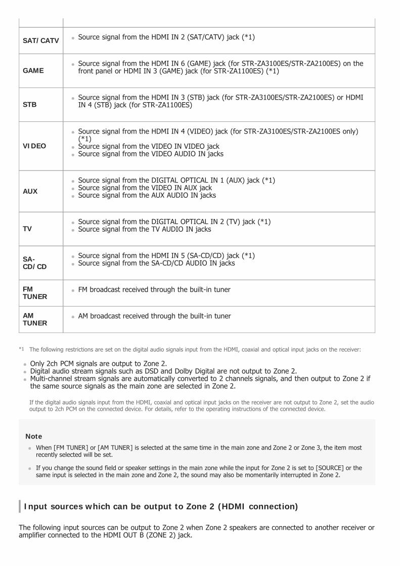
Only 2ch PCM signals are output to Zone 2.Digital audio stream signals such as DSD and Dolby Digital are not output to Zone 2.Multi-channel stream signals are automatically converted to 2 channels signals, and then output to Zone 2 ifthe same source signals as the main zone are selected in Zone 2.
NoteWhen [FM TUNER] or [AM TUNER] is selected at the same time in the main zone and Zone 2 or Zone 3, the item mostrecently selected will be set.
If you change the sound field or speaker settings in the main zone while the input for Zone 2 is set to [SOURCE] or thesame input is selected in the main zone and Zone 2, the sound may also be momentarily interrupted in Zone 2.
Input sources which can be output to Zone 2 (HDMI connection)
The following input sources can be output to Zone 2 when Zone 2 speakers are connected to another receiver oramplifier connected to the HDMI OUT B (ZONE 2) jack.
SAT/CATV Source signal from the HDMI IN 2 (SAT/CATV) jack (*1)
GAMESource signal from the HDMI IN 6 (GAME) jack (for STR-ZA3100ES/STR-ZA2100ES) on thefront panel or HDMI IN 3 (GAME) jack (for STR-ZA1100ES) (*1)
STBSource signal from the HDMI IN 3 (STB) jack (for STR-ZA3100ES/STR-ZA2100ES) or HDMIIN 4 (STB) jack (for STR-ZA1100ES)
VIDEO
Source signal from the HDMI IN 4 (VIDEO) jack (for STR-ZA3100ES/STR-ZA2100ES only)(*1)Source signal from the VIDEO IN VIDEO jackSource signal from the VIDEO AUDIO IN jacks
AUXSource signal from the DIGITAL OPTICAL IN 1 (AUX) jack (*1)Source signal from the VIDEO IN AUX jackSource signal from the AUX AUDIO IN jacks
TVSource signal from the DIGITAL OPTICAL IN 2 (TV) jack (*1)Source signal from the TV AUDIO IN jacks
SA-CD/CD
Source signal from the HDMI IN 5 (SA-CD/CD) jack (*1)Source signal from the SA-CD/CD AUDIO IN jacks
FMTUNER
FM broadcast received through the built-in tuner
AMTUNER
AM broadcast received through the built-in tuner
The following restrictions are set on the digital audio signals input from the HDMI, coaxial and optical input jacks on the receiver:*1
If the digital audio signals input from the HDMI, coaxial and optical input jacks on the receiver are not output to Zone 2, set the audiooutput to 2ch PCM on the connected device. For details, refer to the operating instructions of the connected device.

Only 2ch PCM signals are output to Zone 2.Digital audio stream signals such as DSD and Dolby Digital are not output to Zone 2.Multi-channel stream signals are automatically converted to 2 channels signals, and then output to Zone 2 ifthe same source signals as the main zone are selected in Zone 2.
Inputname Input source
SOURCE Signals from the current input in main zone
BD/DVDSource signal from the HDMI IN 1 (BD/DVD) jackSource signal from the DIGITAL COAXIAL IN (BD/DVD) jack (*2)Source signal from the COMPONENT VIDEO IN 1 (BD/DVD) jacks (*3)
SAT/CATV Source signal from the HDMI IN 2 (SAT/CATV) jack
GAMESource signal from the HDMI IN 6 (GAME) jack (for STR-ZA3100ES/STR-ZA2100ES) on thefront panel or HDMI IN 3 (GAME) jack (for STR-ZA1100ES)
STBSource signal from the HDMI IN 3 (STB) jack (for STR-ZA3100ES/STR-ZA2100ES) or HDMIIN 4 (STB) jack (for STR-ZA1100ES)
VIDEO
Source signal from the HDMI IN 4 (VIDEO) jack (for STR-ZA3100ES/STR-ZA2100ES only)Source signal from the COMPONENT VIDEO IN 2 (VIDEO) jacks (*3)Source signal from the VIDEO IN VIDEO jack (*3)Source signal from the VIDEO AUDIO IN jacks
AUXSource signal from the DIGITAL OPTICAL IN 1 (AUX) jack (*2)Source signal from the VIDEO IN AUX jack (*3)Source signal from the AUX AUDIO IN jacks
TVSource signal from the DIGITAL OPTICAL IN 2 (TV) jack (*2)Source signal from the TV AUDIO IN jacks
SA-CD/CD
Source signal from the HDMI IN 5 (SA-CD/CD) jackSource signal from the SA-CD/CD AUDIO IN jacks
FMTUNER
FM broadcast received through the built-in tuner
AMTUNER
AM broadcast received through the built-in tuner
The following restrictions are set on the digital audio signals input from the coaxial and optical input jacks on the receiver:*2
If the digital audio signals input from the coaxial and optical input jacks on the receiver are not output to Zone 2, set the audio outputto 2ch PCM on the connected device. For details, refer to the operating instructions of the connected device.
The receiver cannot output a different analog signal to the HDMI OUT B (ZONE 2) jack while an analog signal of the main zone isbeing output from the HDMI OUT A jack.
*3

NoteWhen [FM TUNER] or [AM TUNER] is selected at the same time in the main zone and Zone 2 or Zone 3, the item mostrecently selected will be set.
If you change the sound field or speaker settings in the main zone while the input for Zone 2 is set to [SOURCE] or thesame input is selected in the main zone and Zone 2, the sound may also be momentarily interrupted in Zone 2.
Input sources which can be output to Zone 3
The following input sources can be output to Zone 3.You cannot watch video in Zone 3.
NoteWhen [FM TUNER] or [AM TUNER] is selected at the same time in the main zone and Zone 3, the item most recentlyselected will be set.
[73] Using the Multi-Zone Features Enjoying sound from speakers located in another room (Zone 2)
Connecting 5.1-channel speaker system with Zone 2connection
Connect each speaker as illustrated below.Before connecting cables, be sure to disconnect the AC power cord (mains lead).For details on how to connect speaker cables to the receiver, see “How to connect speaker cables.”
Input name Input source
SOURCE Analog audio signals from the current input in main zone
VIDEO Source signal from the VIDEO AUDIO IN jacks
AUX Source signal from the AUX AUDIO IN jacks
TV Source signal from the TV AUDIO IN jacks
SA-CD/CD Source signal from the SA-CD/CD AUDIO IN jacks
FM TUNER FM broadcast received through the built-in tuner
AM TUNER AM broadcast received through the built-in tuner
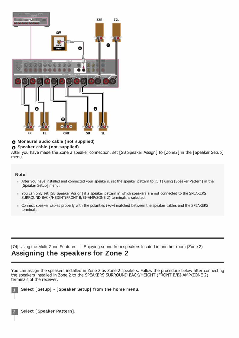
Monaural audio cable (not supplied) Speaker cable (not supplied)
After you have made the Zone 2 speaker connection, set [SB Speaker Assign] to [Zone2] in the [Speaker Setup]menu.
NoteAfter you have installed and connected your speakers, set the speaker pattern to [5.1] using [Speaker Pattern] in the[Speaker Setup] menu.
You can only set [SB Speaker Assign] if a speaker pattern in which speakers are not connected to the SPEAKERSSURROUND BACK/HEIGHT(FRONT B/BI-AMP/ZONE 2) terminals is selected.
Connect speaker cables properly with the polarities (+/–) matched between the speaker cables and the SPEAKERSterminals.
[74] Using the Multi-Zone Features Enjoying sound from speakers located in another room (Zone 2)
Assigning the speakers for Zone 2
You can assign the speakers installed in Zone 2 as Zone 2 speakers. Follow the procedure below after connectingthe speakers installed in Zone 2 to the SPEAKERS SURROUND BACK/HEIGHT (FRONT B/BI-AMP/ZONE 2)terminals of the receiver.
Select [Setup] - [Speaker Setup] from the home menu.1
Select [Speaker Pattern].2
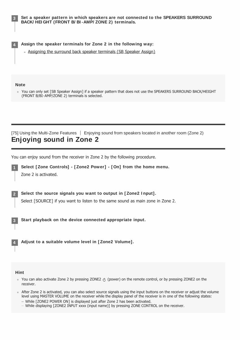
NoteYou can only set [SB Speaker Assign] if a speaker pattern that does not use the SPEAKERS SURROUND BACK/HEIGHT(FRONT B/BI-AMP/ZONE 2) terminals is selected.
[75] Using the Multi-Zone Features Enjoying sound from speakers located in another room (Zone 2)
Enjoying sound in Zone 2
You can enjoy sound from the receiver in Zone 2 by the following procedure.
HintYou can also activate Zone 2 by pressing ZONE2 (power) on the remote control, or by pressing ZONE2 on thereceiver.
After Zone 2 is activated, you can also select source signals using the input buttons on the receiver or adjust the volumelevel using MASTER VOLUME on the receiver while the display panel of the receiver is in one of the following states:
While [ZONE2 POWER ON] is displayed just after Zone 2 has been activated.While displaying [ZONE2 INPUT xxxx (input name)] by pressing ZONE CONTROL on the receiver.
Set a speaker pattern in which speakers are not connected to the SPEAKERS SURROUNDBACK/HEIGHT (FRONT B/BI-AMP/ZONE 2) terminals.
3
Assign the speaker terminals for Zone 2 in the following way:
Assigning the surround back speaker terminals (SB Speaker Assign)
4
Select [Zone Controls] - [Zone2 Power] - [On] from the home menu.
Zone 2 is activated.
1
Select the source signals you want to output in [Zone2 Input].
Select [SOURCE] if you want to listen to the same sound as main zone in Zone 2.
2
Start playback on the device connected appropriate input.3
Adjust to a suitable volume level in [Zone2 Volume].4
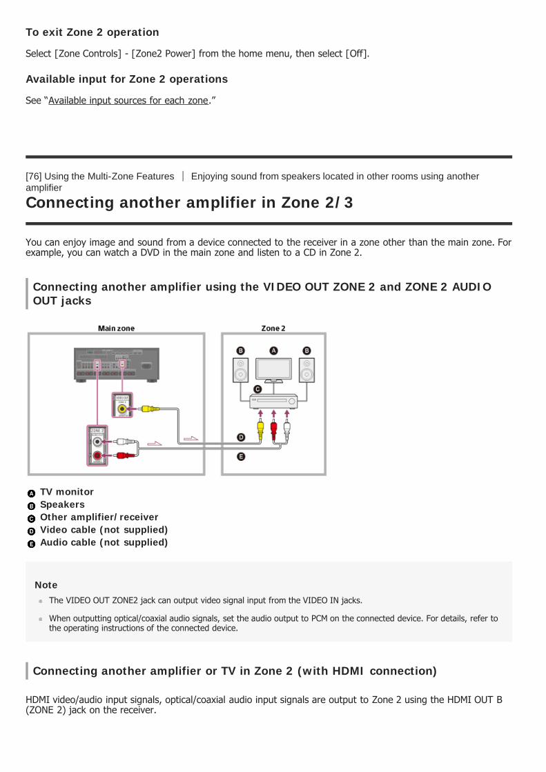
To exit Zone 2 operation
Select [Zone Controls] - [Zone2 Power] from the home menu, then select [Off].
Available input for Zone 2 operations
See “Available input sources for each zone.”
[76] Using the Multi-Zone Features Enjoying sound from speakers located in other rooms using anotheramplifier
Connecting another amplifier in Zone 2/3
You can enjoy image and sound from a device connected to the receiver in a zone other than the main zone. Forexample, you can watch a DVD in the main zone and listen to a CD in Zone 2.
Connecting another amplifier using the VIDEO OUT ZONE 2 and ZONE 2 AUDIOOUT jacks
TV monitor Speakers Other amplifier/receiver Video cable (not supplied) Audio cable (not supplied)
NoteThe VIDEO OUT ZONE2 jack can output video signal input from the VIDEO IN jacks.
When outputting optical/coaxial audio signals, set the audio output to PCM on the connected device. For details, refer tothe operating instructions of the connected device.
Connecting another amplifier or TV in Zone 2 (with HDMI connection)
HDMI video/audio input signals, optical/coaxial audio input signals are output to Zone 2 using the HDMI OUT B(ZONE 2) jack on the receiver.
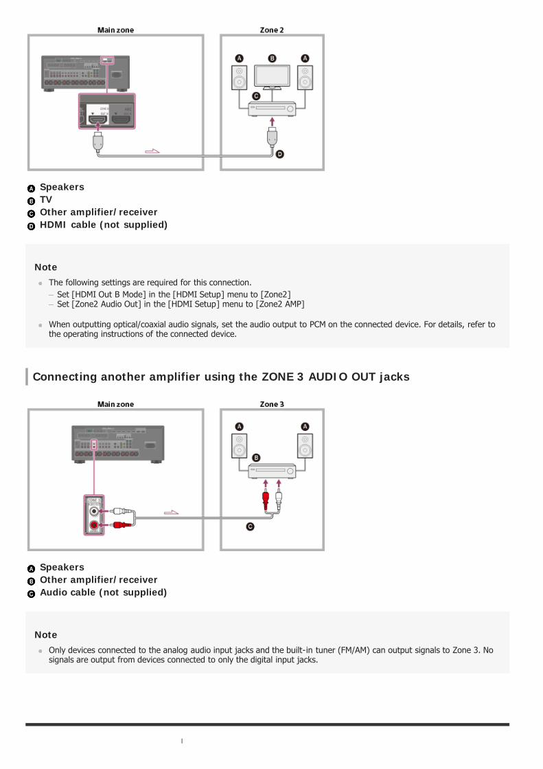
Speakers TV Other amplifier/receiver HDMI cable (not supplied)
NoteThe following settings are required for this connection.
Set [HDMI Out B Mode] in the [HDMI Setup] menu to [Zone2]Set [Zone2 Audio Out] in the [HDMI Setup] menu to [Zone2 AMP]
When outputting optical/coaxial audio signals, set the audio output to PCM on the connected device. For details, refer tothe operating instructions of the connected device.
Connecting another amplifier using the ZONE 3 AUDIO OUT jacks
Speakers Other amplifier/receiver Audio cable (not supplied)
NoteOnly devices connected to the analog audio input jacks and the built-in tuner (FM/AM) can output signals to Zone 3. Nosignals are output from devices connected to only the digital input jacks.

[77] Using the Multi-Zone Features Enjoying sound from speakers located in other rooms using anotheramplifier
Setting the volume control for Zone 2/3 (Zone2/3 Line Out)
You can set variable or fixed volume control for the ZONE 2 AUDIO OUT/ZONE 3 AUDIO OUT jacks.
NoteWhen [Variable] is set, the volume level is turned down by default. Turn up the volume while listening to the sound aftercompleting setup.
[78] Using the Multi-Zone Features Enjoying sound from speakers located in other rooms using anotheramplifier
Setting the Zone 2 HDMI audio output of connected devices(Zone2 Audio Out)
You can set the Zone 2 HDMI audio signal output for playback devices connected to the receiver via an HDMIconnection.
Select [Setup] - [Zone Setup] from the home menu.1
Select [Zone2 Line Out] or [Zone3 Line Out].2
Select the setting you want.
Variable: Select when you cannot adjust the volume level on the amplifier in Zone 2 or Zone 3. Thevolume level of the receiver output in Zone 2 or Zone 3 will become adjustable.Fixed: Select to adjust the volume on the amplifier in Zone 2 or Zone 3. The volume level of thereceiver output in Zone 2 or Zone 3 on the receiver will be fixed.
3
Select [Setup] - [HDMI Setup] from the home menu.1
Select [Zone2 Audio Out].2
Select the setting you want.
AMP: Recommended setting when a TV is connected directly to the HDMI OUT B (ZONE 2) jack.Sound is output from the speakers connected to the receiver.Sound is not output from the TV speakers.
Zone2 TV + AMP: Recommended setting when a TV is connected directly to the HDMI OUT B (ZONE2) jack.
3

NoteYou can only configure this setting when [HDMI Out B Mode] is set to [Zone2].
When a video device (projector, etc.) is connected to the HDMI OUT B (ZONE 2) jack, sound may not be output from thereceiver. In this case, set [Zone2 Audio Out] to [AMP].
When a TV which does not support audio content protection is connected to the HDMI OUT B (ZONE 2) jack, specificaudio may not be output from the receiver. In this case, set [Zone2 Audio Out] to [AMP].
When [Zone2 Audio Out] is set to [Zone2 TV + AMP] or [AMP], audio signals will be downmixed. The followingrestrictions apply to downmixing.
If you change the sound field or speaker settings in the main zone while the input for Zone 2 is set to SOURCE or thesame input is selected in the main zone and Zone 2, the sound may also be momentarily interrupted in Zone 2.The D.L.L. function does not work in the main zone.The volume level of sound from the SPEAKERS SURROUND BACK/HEIGHT (FRONT B/BI-AMP/ZONE 2) terminals andthe HDMI OUT B (ZONE 2) jack may be different from sound that is not downmixed.
No sound will be output to Zone 2 if you play a DTS-CD with different HDMI inputs selected in the main zone and Zone2.
You cannot remedy the time gap between video output on the TV connected to the HDMI OUT B (ZONE 2) jack andaudio output from the speaker connected to the SPEAKERS SURROUND BACK/HEIGHT (FRONT B/BI-AMP/ZONE 2)terminals using the A/V Sync function.
[79] Using the Multi-Zone Features Enjoying sound from speakers located in other rooms using anotheramplifier
Setting the priority for the main zone (Priority)
Lets you set the priority when you select the same input for both the main zone and Zone 2.
Sound is output from the TV speakers and the speakers connected to the receiver.
Zone2 AMP: Recommended setting when another amplifier is connected to the HDMI OUT B (ZONE 2)jack.Sound is output from the another amplifier connected to the HDMI OUT B (ZONE 2) jack.Sound is not output from the SPEAKERS SURROUND BACK/HEIGHT (FRONT B/BI-AMP/ZONE 2)terminals and the ZONE 2 AUDIO OUT jacks.
Select [Setup] - [HDMI Setup] from the home menu.1
Set [Priority].
Main & Zone2: You can enjoy the same input in the main zone and Zone 2. However, there may besome interference in the audio and video signals in the main zone and Zone 2.
Main Only: You can enjoy good audio and video quality in the main zone. There is no output in Zone2.
2
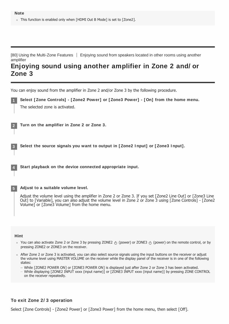
NoteThis function is enabled only when [HDMI Out B Mode] is set to [Zone2].
[80] Using the Multi-Zone Features Enjoying sound from speakers located in other rooms using anotheramplifier
Enjoying sound using another amplifier in Zone 2 and/orZone 3
You can enjoy sound from the amplifier in Zone 2 and/or Zone 3 by the following procedure.
HintYou can also activate Zone 2 or Zone 3 by pressing ZONE2 (power) or ZONE3 (power) on the remote control, or bypressing ZONE2 or ZONE3 on the receiver.
After Zone 2 or Zone 3 is activated, you can also select source signals using the input buttons on the receiver or adjustthe volume level using MASTER VOLUME on the receiver while the display panel of the receiver is in one of the followingstates:
While [ZONE2 POWER ON] or [ZONE3 POWER ON] is displayed just after Zone 2 or Zone 3 has been activated.While displaying [ZONE2 INPUT xxxx (input name)] or [ZONE3 INPUT xxxx (input name)] by pressing ZONE CONTROLon the receiver repeatedly.
To exit Zone 2/3 operation
Select [Zone Controls] - [Zone2 Power] or [Zone3 Power] from the home menu, then select [Off].
Select [Zone Controls] - [Zone2 Power] or [Zone3 Power] - [On] from the home menu.
The selected zone is activated.
1
Turn on the amplifier in Zone 2 or Zone 3.2
Select the source signals you want to output in [Zone2 Input] or [Zone3 Input].3
Start playback on the device connected appropriate input.4
Adjust to a suitable volume level.
Adjust the volume level using the amplifier in Zone 2 or Zone 3. If you set [Zone2 Line Out] or [Zone3 LineOut] to [Variable], you can also adjust the volume level in Zone 2 or Zone 3 using [Zone Controls] - [Zone2Volume] or [Zone3 Volume] from the home menu.
5
Available input for Zone 2/3 operations
See “Available input sources for each zone.”
[81] Using Other Features Interlocking with BRAVIA TV and other devices (“BRAVIA” Sync)
What is “BRAVIA” Sync?
“BRAVIA” Sync is an extended function developed by Sony based on the Control for HDMI (*1) function. Byconnecting “BRAVIA” Sync-compatible devices, such as a TV or a Blu-ray Disc player, using an HDMI cable (*2)(not supplied) you can control the devices with the TV remote control. The following functions can be used with“BRAVIA” Sync.
Turning off the receiver and connected devices simultaneously with the TV (System Power Off function)(Standby Linked to TV)Enjoying TV sound from the speakers connected to the receiver (System Audio Control function)Enjoying sound of an ARC compatible TV (Audio Return Channel)Enjoying an input source from a connected device immediately (One-Touch Play function)Operating the receiver menu using the TV remote control (Remote Easy Control function)Enjoying content of a connected device without turning on the receiver (Standby Through)Selecting the optimum picture quality and sound field automatically (Scene Select function)Echo Canceling functionAbout Language Follow function
NoteFunctions such as System Power Off, System Audio Control, One-Touch Play, and Remote Easy Control may be usedwith other devices than those manufactured by Sony that support the Control for HDMI function. However, compatibilitywith other devices than those manufactured by Sony is not guaranteed.
[82] Using Other Features Interlocking with BRAVIA TV and other devices (“BRAVIA” Sync)
Preparing for “BRAVIA” Sync
Turn the Control for HDMI function on to use the “BRAVIA” Sync function. The Control for HDMI function needsto be turned on separately for the receiver and the connected device.
Control for HDMI is a standard used by CEC (Consumer Electronics Control) specification that enables interoperability of connecteddevices for HDMI (High-Definition Multimedia Interface) connections.
*1
Sony recommends a Premium High Speed HDMI Cable with Ethernet that supports 18 Gbps.*2
Select [Setup] - [HDMI Setup] from the home menu.1
Select [Control for HDMI].2
Select [On].3

NotePerform the steps above again if you unplug the HDMI cable or change the connection.
This function is enabled only when [HDMI Out B Mode] is set to [Main].
[83] Using Other Features Interlocking with BRAVIA TV and other devices (“BRAVIA” Sync)
Turning off the receiver and connected devicessimultaneously with the TV (System Power Off function)(Standby Linked to TV)
You can turn off the receiver and the connected device automatically when you turn off the TV.
The Control for HDMI function of the receiver is turned on.
Press HOME to return to the home menu.4
Press HOME to exit the home menu.5
Select the HDMI input of the receiver to match the HDMI input of the connected device, sothat the image from the connected device is displayed.
6
Turn on the Control for HDMI function of the connected device.
For details on setting the connected device, refer to the operating instructions of the respective devices.
7
Repeat steps 6 and 7 for other devices for which you want to use the Control for HDMIfunction.
8
Select [Setup] - [HDMI Setup] from the home menu.1
Select [Standby Linked to TV].2
Select the setting you want.3

NoteThis setting is valid when [Control for HDMI] is set to [On].
The connected device may not turn off depending on the status of the device.
System Power Off function may work with devices other than those manufactured by Sony, but operation is notguaranteed.
[84] Using Other Features Interlocking with BRAVIA TV and other devices (“BRAVIA” Sync)
Enjoying TV sound from the speakers connected to thereceiver (System Audio Control function)
If you turn on the receiver while you are watching the TV, the TV sound will be output from the speakersconnected to the receiver. The volume of the receiver can be adjusted using the TV remote control.If the TV sound was output from the speakers connected to the receiver last time you watched the TV, thereceiver will be turned on automatically when you turn on the TV again.Operations can also be made using the TV menu. For details, refer to the operating instructions of the TV.
NoteDepending on the TV, the number of the receiver volume level is displayed on the TV screen. The volume numberdisplayed on the TV may differ from the number on the front panel display of the receiver.
System Audio Control function may work with other devices than those manufactured by Sony, but operation is notguaranteed.
Depending on the settings of the TV, the System Audio Control function may not be available. For details, refer to theoperating instructions of the TV.
When [Control for HDMI] is set to [On], the [Audio Out] settings in the [HDMI Setup] menu will be set automaticallyaccording to the setting of the System Audio Control function.
[85] Using Other Features Interlocking with BRAVIA TV and other devices (“BRAVIA” Sync)
Enjoying an input source from a connected deviceimmediately (One-Touch Play function)
Auto: If either of the following inputs is selected on the receiver, the receiver will turn off when the TVis turned off:
[TV]An input assigned with either [HDMI], [COMPONENT] or [COMPOSITE] for video using [InputAssign]An input assigned with [HDMI] for audio using [Input Assign]
On: The receiver will turn off when the TV is turned off regardless of the input of the receiver.Off: The power of the receiver does not turn off when the TV is turned off, regardless of the input ofthe receiver.

When you play content on a device (Blu-ray Disc player, PlayStation®4, etc.) connected to the receiver, thereceiver and the TV are turned on automatically, the input of the receiver is switched to the input of the devicebeing played, and sound is output from the speakers connected to the receiver.
NoteIf [Standby Through] is set to [Auto] or [On], and the TV sound was output from the speakers of the TV last time youwatched the TV, the receiver does not turn on and the sound and picture are output from the TV even if you play contenton the device.
Depending on the TV, the beginning part of content being played may not play correctly.
One-Touch Play function may work with other devices than those manufactured by Sony, but operation is notguaranteed.
[86] Using Other Features Interlocking with BRAVIA TV and other devices (“BRAVIA” Sync)
Selecting the optimum picture quality and sound fieldautomatically (Scene Select function)
The sound field are selected automatically according to the Scene Select setting on your TV.For details on this operation, refer to the operating instructions of the TV.
The Scene Select/Sound Mode setting and the sound field setting of the receiver will change as follows.
Cinema: Dolby SurroundSports: Dolby SurroundMusic: Dolby SurroundAnimation: Dolby SurroundPhoto: Multi StereoGame: Dolby SurroundGraphics: Multi StereoNews: Multi Stereo
NoteThe Scene Select function is a function developed by Sony, and cannot be used on other devices than thosemanufactured by Sony.
[87] Using Other Features Interlocking with BRAVIA TV and other devices (“BRAVIA” Sync)
Operating the receiver menu using the TV remote control(Remote Easy Control function)
You can select the receiver by the SYNC MENU of the TV and operate the receiver. This function can be used ifthe TV supports the SYNC MENU. For details, refer to the operating instructions of the TV.

NoteThe receiver is recognized as [Tuner] by the TV.
Some of the operations may not be available depending on the type of TV.
Remote Easy Control function may work with other devices than those manufactured by Sony, but operation is notguaranteed.
[88] Using Other Features Interlocking with BRAVIA TV and other devices (“BRAVIA” Sync)
Echo Canceling function
The Echo Canceling function reduces reverberation that may occur when using the Social Viewing functions suchas Skype while watching TV programs. This function can be used if the TV supports the Social Viewing functions.For details, refer to the operating instructions of the TV.
NoteThe Echo Canceling function works when you select [TV] or an HDMI input jack to which the device is connected as theinput on the receiver.
When you use the Social Viewing function, the input of the receiver is switched automatically to the input to which theTV is connected, even if another HDMI input jack has been selected. The sound from the Social Viewing function and theTV will be output from the speakers connected to the receiver.
This function cannot be used when the sound is output from the TV.
The Echo Canceling function is a function developed by Sony, and cannot be used on other devices than thosemanufactured by Sony.
[89] Using Other Features Interlocking with BRAVIA TV and other devices (“BRAVIA” Sync)
About Language Follow function
While the receiver is turned on, the on-screen display language of the receiver may be changed simultaneouslywhen you change the language for the on-screen display of the TV.
[90] Using Other Features Enjoying video and sound with your desired way of use
Switching the monitors that output the HDMI video signals
If you have connected two monitors to the HDMI OUT A and HDMI OUT B (ZONE 2) jacks, you can switch theoutput for these two monitors using the HDMI OUTPUT button on the remote control.
Turn on the receiver and the two monitors.1
Note[HDMI OUT A+B] may not work if the compatible video formats of the monitors connected to the HDMI OUT A jack andthe HDMI OUT B (ZONE 2) jack of the receiver are different.
[HDMI OUT A+B] may not work depending on the playback device you connect.
HintYou can also use HDMI OUT on the receiver to switch the monitor.
[91] Using Other Features Enjoying video and sound with your desired way of use
Switching between digital and analog audio (Input Mode)
When you connect devices to both digital and analog audio input jacks on the receiver, you can fix the audioinput mode to either device, or switch from one to the other, depending on the type of material you intend towatch.
[92] Using Other Features Enjoying video and sound with your desired way of use
Using other video/audio input jacks (Input Assignment)
You can reassign video and/or audio signals to other input jacks if the default settings of the jacks do not
Press HDMI OUTPUT.
Each time you press the button, the output will be switched as follows:[HDMI OUT A] - [HDMI OUT B] (*) - [HDMI OUT A+B] (*) - [HDMI OUT OFF]
2
Unavailable when [HDMI Out B Mode] is set to [Zone2].*
Select [Setup] - [Input Setup] from the home menu.1
Select the [Input Mode] setting for the input you want.
Auto: Gives priority to digital audio signals. If there is more than one digital connection, HDMI audiosignals have priority. If there is no digital audio signals, analog audio signals are selected. When TV input is selected, priorityis given to Audio Return Channel (ARC) signals. If your TV does not support the ARC function, digitaloptical audio signals are selected.Optical: Specifies input of digital audio signals to the OPTICAL jack.Coaxial: Specifies input of digital audio signals to the COAXIAL jack.Analog: Specifies input of analog audio signals to the AUDIO IN (L/R) jacks.
2

correspond to your connected device.
E.g. When connecting a DVD player to the OPTICAL IN 1 (AUX) and COMPONENT VIDEO IN 2 (VIDEO) jacks ofthe receiver:
Assign [BD/DVD] to the OPTICAL IN 1 (AUX) jack.Assign [BD/DVD] to the COMPONENT VIDEO IN 2 (VIDEO) jack.
Assignable HDMI input jacks (for STR-ZA3100ES/STR-ZA2100ES)
IN 1:BD/DVD (*), SAT/CATV, GAME, STB, VIDEO, AUX, TV, SA-CD/CD
IN 2:BD/DVD, SAT/CATV (*), GAME, STB, VIDEO, AUX, TV, SA-CD/CD
IN 3:BD/DVD, SAT/CATV, GAME, STB (*), VIDEO, AUX, TV, SA-CD/CD
IN 4:BD/DVD, SAT/CATV, GAME, STB, VIDEO (*), AUX, TV, SA-CD/CD
IN 5:BD/DVD, SAT/CATV, GAME, STB, VIDEO, AUX, TV, SA-CD/CD (*)
IN 6:BD/DVD, SAT/CATV, GAME (*), STB, VIDEO, AUX, TV, SA-CD/CD
None:BD/DVD, SAT/CATV, GAME, STB, VIDEO, AUX (*), TV (*), SA-CD/CD
Assignable HDMI input jacks (for STR-ZA1100ES)
IN 1:BD/DVD (*), SAT/CATV, GAME, STB, VIDEO, AUX, TV, SA-CD/CD
IN 2:BD/DVD, SAT/CATV (*), GAME, STB, VIDEO, AUX, TV, SA-CD/CD
IN 3:BD/DVD, SAT/CATV, GAME (*), STB, VIDEO, AUX, TV, SA-CD/CD
IN 4:BD/DVD, SAT/CATV, GAME, STB (*), VIDEO, AUX, TV, SA-CD/CD
Select [Setup] - [Input Setup] from the home menu.1
Select [BD/DVD].2
Press repeatedly to select [COAX] under [OPTICAL / COAXIAL] and / repeatedly toselect [OPT 1].
3
Press repeatedly to select [IN 1] under [COMPONENT] and / repeatedly to select [IN2].
4
Default setting*
IN 5:BD/DVD, SAT/CATV, GAME, STB, VIDEO, AUX, TV, SA-CD/CD (*)
None:BD/DVD, SAT/CATV, GAME, STB, VIDEO(*), AUX (*), TV (*), SA-CD/CD
Assignable OPTICAL / COAXIAL input jacks
OPT 1:BD/DVD, SAT/CATV, GAME, STB, VIDEO, AUX (*), TV, SA-CD/CD
OPT 2:BD/DVD, SAT/CATV, GAME, STB, VIDEO, AUX, TV (*), SA-CD/CD
COAX:BD/DVD (*), SAT/CATV, GAME, STB, VIDEO, AUX, TV, SA-CD/CD
None:BD/DVD, SAT/CATV (*), GAME (*), STB (*), VIDEO (*), AUX, TV, SA-CD/CD (*)
NoteWhen you assign the digital audio input, the Input Mode setting may change automatically.
One reassignment is allowed for each input.
If no sound is output from the assigned jacks, also check the Input Mode settings.
[93] Using Other Features Saving and recalling various settings for the receiver (Custom Preset)
About Custom Preset
You can save various settings with the player, monitor, etc., according to your listening and viewing style. Youcan register those settings for “one-touch” operation, and then recall the environment created with the settingseasily.For example, by saving the settings in the [1: Movie] preset as follows, you can switch the settings of thereceiver all at one time without switching each setting for [Input], [Calibration Type], and [Sound Field]individually.
Input: BD/DVDSound Field: Dolby SurroundCalibration Type: No change
[94] Using Other Features Saving and recalling various settings for the receiver (Custom Preset)
Saving the settings to a preset
Default setting*
Default setting*
Select [Custom Preset] from the home menu.1

NoteSettings for which the box is unchecked are not changed from the present settings even when you recall the presetsettings. Select [Edit], then uncheck the box for a setting item on the edit screen.
HintYou can overwrite [1: Movie], [2: Music], [3: Party] or [4: Night] with the present settings by holding down CUSTOMPRESET 1, CUSTOM PRESET 2, CUSTOM PRESET 3 or CUSTOM PRESET 4 for 3 seconds in the same way as you dowhen you select [Import] from the menu.
When you select [3: Party], Zone 2 and Zone 3 are turned on automatically and you can simultaneously enjoy the samemusic as the main zone in these zones.
[95] Using Other Features Saving and recalling various settings for the receiver (Custom Preset)
Recalling the settings saved to the scene
HintYou can recall the setting(s) saved for [1: Movie], [2: Music], [3: Party] or [4: Night] directly by pressing CUSTOMPRESET 1, CUSTOM PRESET 2, CUSTOM PRESET 3 or CUSTOM PRESET 4 on the remote control.
[96] Using Other Features Saving and recalling various settings for the receiver (Custom Preset)
Items for which you can save settings and the default values
Press OPTIONS with a preset for which you want to edit settings among from [1: Movie], [2:Music], [3: Party] or [4: Night] selected.
2
Select the menu you want from the options menu.
Edit: Allows you to customize and save the settings to suit your preferences.Import: Loads the present settings of the receiver and saves those settings with the preset. [Input]and [Volume] are not changed.
3
Select [Custom Preset] from the home menu.1
Select a preset you want.2

for each item
1: MoviePreset Name: MovieInput: BD/DVDTuner Preset: No changeVolume: No changeHDMI OUT: No changeParty Mode: No changeSleep: No changeSound Field: Multi StereoSound Optimizer: No changeIn-Ceiling Speaker Mode: No changePure Direct: No changeCalibration Type: No changeFront Bass: No changeFront Treble: No changeCenter Bass: No changeCenter Treble: No changeSurround Bass: No changeSurround Treble: No changeHeight1 Bass (*1): No changeHeight1 Treble (*1): No changeHeight2 Bass (*1): No changeHeight2 Treble (*1): No changeHeight Bass (*2): No changeHeight Treble (*2): No change
2: MusicPreset Name: MusicInput: SA-CD/CDTuner Preset: No changeVolume: No changeHDMI OUT: No changeParty Mode: No changeSleep: No changeSound Field: Multi StereoSound Optimizer: No changeIn-Ceiling Speaker Mode: No changePure Direct: No changeCalibration Type: No changeFront Bass: No changeFront Treble: No changeCenter Bass: No changeCenter Treble: No changeSurround Bass: No changeSurround Treble: No changeHeight1 Bass (*1): No changeHeight1 Treble (*1): No changeHeight2 Bass (*1): No changeHeight2 Treble (*1): No changeHeight Bass (*2): No changeHeight Treble (*2): No change
3: PartyPreset Name: PartyInput: No changeTuner Preset: No changeVolume: -23.0 dBHDMI OUT: No changeParty Mode: OnSleep: OffSound Field: Multi StereoSound Optimizer: OffIn-Ceiling Speaker Mode: No change

Pure Direct: No changeCalibration Type: No changeFront Bass: No changeFront Treble: No changeCenter Bass: No changeCenter Treble: No changeSurround Bass: No changeSurround Treble: No changeHeight1 Bass (*1): No changeHeight1 Treble (*1): No changeHeight2 Bass (*1): No changeHeight2 Treble (*1): No changeHeight Bass (*2): No changeHeight Treble (*2): No change
4: NightPreset Name: NightInput: No changeTuner Preset: No changeVolume: -44.5 dBHDMI OUT: No changeParty Mode: No changeSleep: 0:30:00Sound Field: No changeSound Optimizer: NormalIn-Ceiling Speaker Mode: No changePure Direct: No changeCalibration Type: No changeFront Bass: No changeFront Treble: No changeCenter Bass: No changeCenter Treble: No changeSurround Bass: No changeSurround Treble: No changeHeight1 Bass (*1): No changeHeight1 Treble (*1): No changeHeight2 Bass (*1): No changeHeight2 Treble (*1): No changeHeight Bass (*2): No changeHeight Treble (*2): No change
[97] Using Other Features
Using the sleep timer (Sleep)
You can set the receiver to turn off automatically after a specified period of time.
for STR-ZA3100ES/STR-ZA2100ES*1for STR-ZA1100ES*2
Select [Setup] - [System Setup] from the home menu.1
Select [Sleep].2
Set specified time.
2:00:00
3
HintYou can check the remaining time before the receiver turns off on the System Setup screen. Also, the remaining timeappears on the bottom right of the TV screen when it becomes 1 minute or less.
The sleep timer will be canceled if you perform the following:Update the software of the receiver.Turn the receiver on or off.
[98] Using Other Features
Viewing information on the display panel
The display panel provides various information on the status of the receiver, such as the sound field.
NoteCharacters or marks in some languages may not be displayed.
1:30:001:00:000:30:00Off
[SLEEP] lights up on the display panel of the receiver when sleep timer is being used.
Select the input for which you want to check information.1
Press DISPLAY repeatedly.
The default input name or the input name you have set is displayed on the upper line of the display panel. The lower line of the display panel will change sequentially as follows each time you press DISPLAY:currently applied sound field (*1)→stream information (*2)→default input name (*3).
When listening to FM or AM radio
The band, preset number, and preset station name (*4) or frequency are displayed on the upper line of thedisplay panel.The currently applied sound field is displayed on the lower line of the display panel.
2
[PURE DIRECT] appears on the display panel when the Pure Direct function is activated.*1Stream Information is not displayed when no signals can be found for the selected input.*2Appears only when you have set an arbitrary input name.*3Appears only when you have set an arbitrary preset station name. In this case, the preset station name and frequency are displayedalternately each time you press DISPLAY.
*4

[99] Adjusting Settings Easy Setup
Setting up the receiver using the Easy Setup
When you turn on the receiver for the first time or after the receiver is initialized, the Easy Setup screen appearson the TV screen. You can set up the following settings for the receiver by following the instructions on the EasySetup screen.
Auto Calibration
Check your speaker system and perform automatic calibration according to the configuration andarrangement of your speaker system.
Internet Setup
Configure settings to connect the receiver to the network.
NoteSwitch the input of the TV to the input to which the receiver is connected to use this function.
If the Easy Setup screen does not appear or you want to display the Easy Setup screen manually, you candisplay it by selecting [Setup] - [Easy Setup] from the home menu.
[100] Adjusting Settings Input Setup
Changing the assignment and display for the input jacks
You can customize the settings for each input according to your preferences and usage.Select [Setup] - [Input Setup] from the home menu, then set each item shown below.
Input
You can change the settings of [Icon], [Name], [Watch/Listen], [Show/Hide], [HDMI], [OPTICAL / COAXIAL],[COMPONENT], [VIDEO IN], [AUDIO IN], [Input Mode], [Preset Sound Field], [In-Ceiling Speaker Mode], [A/VSync], [Subwoofer Low Pass Filter], [Subwoofer Level], [Preset Gain Level], [Trigger 1] (*1), [Trigger 2] (*1),[Trigger 3] (*1) and [Trigger] (*2) for the desired input.
NoteThe settings of [AUDIO IN] on the Input Setup screen are fixed.
Icon
You can set the icon displayed on the Watch/Listen menu.
Name
You can change the name displayed on the Watch/Listen menu.
for STR-ZA3100ES*1for STR-ZA2100ES/STR-ZA1100ES*2
Watch/Listen
You can set whether an input is displayed on the Watch menu or the Listen menu.
Watch: Displays an input to the Watch menu.Listen: Displays an input to the Listen menu.Watch/Listen: Displays an input to both the Watch and Listen menus.
Show/Hide
You can set whether or not an input is displayed.
Show: Shows the input.Hide: Hides the input.
HDMI
You can assign HDMI input jacks for each input.
OPTICAL / COAXIAL
You can set the digital audio input jack(s) assigned to each input.
OPT 1OPT 2COAXNone
COMPONENT
You can set the video input jack(s) assigned to each input.
IN 1IN 2None
VIDEO IN
You can set the composite video input jack(s) assigned to VIDEO IN (VIDEO) or VIDEO IN (AUX) input signal.
AUDIO IN
Indicates an analog signal is being input.
Input Mode
You can set the input mode for each input.
Preset Sound Field
You can assign a default “Sound Field” to each input source that will be selected automatically when you selectthe input source.
In-Ceiling Speaker Mode
You can select whether or not to use the In-Ceiling Speaker Mode with the current input.
A/V Sync
You can delay the output of audio to minimize the time gap between audio output and visual display.
Subwoofer Low Pass Filter

You can turn on or off the low-pass filter for the subwoofer output. The low-pass filter works when PCM signalsare input via an HDMI connection. You can set the function for each input to which an HDMI input jack isassigned independently. Turn the function on if you connect a subwoofer without the crossover frequencyfunction.
Subwoofer Level
You can set the level of the subwoofer to 0 dB or +10 dB when PCM signals are input via an HDMI connection.You can set the level for each input to which an HDMI input jack is assigned independently.
Preset Gain Level
You can preset the gain level for each input.
Trigger 1 to 3 (for STR-ZA3100ES) Trigger (for STR-ZA2100ES/STR-ZA1100ES)
You can select input options for use of the 12V Trigger function.
[101] Adjusting Settings Input Setup
Changing the name for each input (Name)
You can enter up to 8 characters for each input name.
[102] Adjusting Settings Speaker Setup
1. About Auto Calibration
Select [Setup] - [Input Setup] from the home menu.1
Select the input name you want to change.2
Select [Name].
An on-screen keyboard appears on the TV screen.
3
Press / / / and to select characters one by one to enter the name.4
Select [Enter].
The name you entered is registered.
5

Auto Calibration allows you to perform automatic calibration as follows.
Check the connection between each speaker and the receiver.Adjust the speaker level.Measure the distance of each speaker from your seating position. (*1)Measure the speaker size. (*1)Measure the frequency characteristics (EQ). (*1)Measure the frequency characteristics (Phase). (*1) (*2)
NoteThe D.C.A.C. is designed to achieve proper sound balance for your room. However, you can adjust the speaker levelsmanually according to your preference using [Test Tone].
[103] Adjusting Settings Speaker Setup
2. Before you perform Auto Calibration
Before you perform Auto Calibration, check the following items:
Set up and connect the speakers.Do not connect any microphones other than the supplied calibration microphone to the CALIBRATION MICjack.If using a bi-amplifier connection or speakers with a front B connection, set the assignment for theSPEAKERS SURROUND BACK/HEIGHT (FRONT B/BI-AMP/ZONE 2) terminals properly. For details, see“Assigning the surround back speaker terminals (SB Speaker Assign).”Set the speaker output to a setting other than [SPEAKERS OFF]. For details, see “4. Selecting the frontspeakers.”Remove any obstructions between the calibration microphone and the speakers.For accurate measurement, make sure the environment is quiet and free from noise.
NoteThe speakers emit very loud sound during the calibration and the volume cannot be adjusted. Be considerate of yourneighbors and any children who are present.
If the muting function has been activated before you perform Auto Calibration, the muting function will shut offautomatically.
It may not be possible to take the correct measurements or to perform Auto Calibration at all if special speakers such asdipole speakers are used.
[104] Adjusting Settings Speaker Setup
3. Connecting the calibration microphone
The measurement result is not utilized when [Direct] is being used and an analog input is selected.*1The measurement result may be not utilized, depending on the audio formats.*2
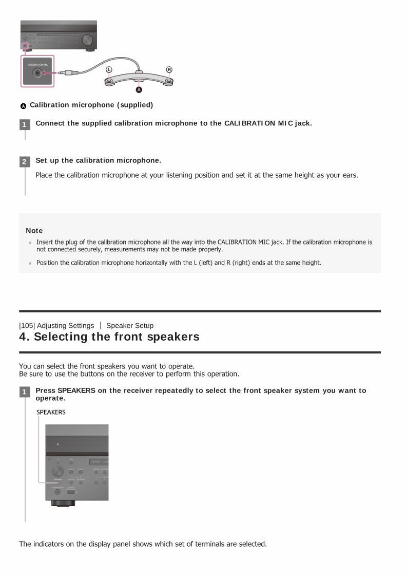
Calibration microphone (supplied)
NoteInsert the plug of the calibration microphone all the way into the CALIBRATION MIC jack. If the calibration microphone isnot connected securely, measurements may not be made properly.
Position the calibration microphone horizontally with the L (left) and R (right) ends at the same height.
[105] Adjusting Settings Speaker Setup
4. Selecting the front speakers
You can select the front speakers you want to operate. Be sure to use the buttons on the receiver to perform this operation.
The indicators on the display panel shows which set of terminals are selected.
Connect the supplied calibration microphone to the CALIBRATION MIC jack.1
Set up the calibration microphone.
Place the calibration microphone at your listening position and set it at the same height as your ears.
2
Press SPEAKERS on the receiver repeatedly to select the front speaker system you want tooperate.
1
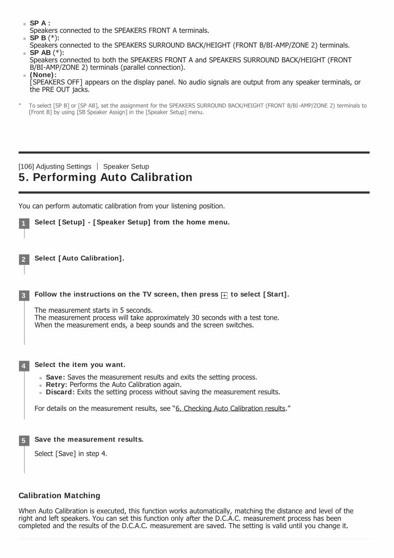
SP A : Speakers connected to the SPEAKERS FRONT A terminals.SP B (*):Speakers connected to the SPEAKERS SURROUND BACK/HEIGHT (FRONT B/BI-AMP/ZONE 2) terminals.SP AB (*):Speakers connected to both the SPEAKERS FRONT A and SPEAKERS SURROUND BACK/HEIGHT (FRONTB/BI-AMP/ZONE 2) terminals (parallel connection).(None): [SPEAKERS OFF] appears on the display panel. No audio signals are output from any speaker terminals, orthe PRE OUT jacks.
[106] Adjusting Settings Speaker Setup
5. Performing Auto Calibration
You can perform automatic calibration from your listening position.
Calibration Matching
When Auto Calibration is executed, this function works automatically, matching the distance and level of theright and left speakers. You can set this function only after the D.C.A.C. measurement process has beencompleted and the results of the D.C.A.C. measurement are saved. The setting is valid until you change it.
To select [SP B] or [SP AB], set the assignment for the SPEAKERS SURROUND BACK/HEIGHT (FRONT B/BI-AMP/ZONE 2) terminals to[Front B] by using [SB Speaker Assign] in the [Speaker Setup] menu.
*
Select [Setup] - [Speaker Setup] from the home menu.1
Select [Auto Calibration].2
Follow the instructions on the TV screen, then press to select [Start].
The measurement starts in 5 seconds. The measurement process will take approximately 30 seconds with a test tone.When the measurement ends, a beep sounds and the screen switches.
3
Select the item you want.
Save: Saves the measurement results and exits the setting process.Retry: Performs the Auto Calibration again.Discard: Exits the setting process without saving the measurement results.
For details on the measurement results, see “6. Checking Auto Calibration results.”
4
Save the measurement results.
Select [Save] in step 4.
5
NoteIf an error code or warning message appears on the screen in step 3, see “List of messages after Auto Calibrationmeasurements.”
HintYou can also perform automatic calibration by pressing the AUTO CAL button on the remote control. If you use the AUTOCAL button, the following restrictions apply to the operation:
Prior settings relating to the Auto Calibration will be skipped.You can only use the display panel for the operation.
The Auto Calibration function will be canceled if you perform the following during the measurement process:Turn the receiver on or off.Press the input buttons on the remote control or on the receiver.Press .Press SPEAKERS on the receiver.Press HDMI OUTPUT.Press AMP MENU.Press HOME.Press AUTO CAL.Change the volume level.
[107] Adjusting Settings Speaker Setup
6. Checking Auto Calibration results
To check error codes or warning messages received in [Auto Calibration], proceed with the following steps:
If an error code appears
Check the error and perform Auto Calibration again.
Select [Retry].1
Follow the instructions on the TV screen and then press to select [Start].
The measurement starts in 5 seconds. The measurement process will take approximately 30 seconds with a test tone.When the measurement ends, a beep sounds and the screen switches.
2
Select the item you want.
Save: Saves the measurement results and exits the setting process.Retry: Performs the Auto Calibration again.Discard: Exits the setting process without saving the measurement results.
3
Save the measurement results.4

If a warning message appears
Check the warning message and select [OK]. For details on the warning messages, see “List of messages afterAuto Calibration measurements.”
HintThe measurement results may vary depending on the position of the subwoofer. However, continuing to use the receiverwith that value does not cause problems.
[108] Adjusting Settings Speaker Setup
Calibrating the phase characteristics of the speakers(Automatic Phase Matching)
You can set the A.P.M. (Automatic Phase Matching) function in the D.C.A.C. (Digital Cinema Auto Calibration).This calibrates the phase characteristics of the speakers for well-coordinated surround sound.
NoteThis function does not work in the following cases:
[Direct] is being used and an analog input is selected.[Auto Calibration] has not been performed.
The receiver may play signals at a lower sampling frequency than the actual sampling frequency of the input signals,depending on the audio format.
[109] Adjusting Settings Speaker Setup
Select [Save] in step 3.
Select [Setup] - [Speaker Setup] from the home menu.1
Select [Automatic Phase Matching].2
Select the setting you want.
Auto: Switches the A.P.M. function on or off automatically.Off
3
Selecting the Auto Calibration type (Calibration Type)
You can select a calibration type after you have performed the Auto Calibration and saved the settings.
NoteThis function does not work when [Direct] is being used and an analog input is selected.
The receiver may play signals at a lower sampling frequency than the actual sampling frequency of the input signals,depending on the audio format.
[110] Adjusting Settings Speaker Setup
Selecting the speaker pattern (Speaker Pattern)
You can select the speaker pattern according to the speaker system which you are using.
[111] Adjusting Settings Speaker Setup
Select [Setup] - [Speaker Setup] from the home menu.1
Select [Calibration Type].2
Select the setting you want.
Full Flat: Makes the measurement of frequency from each speaker flat.Engineer: Sets to “the Sony listening room standard” frequency characteristics.Front Reference: Adjusts the characteristics of all of the speakers to match the characteristics of thefront speaker.Off
3
Select [Setup] - [Speaker Setup] from the home menu.1
Select [Speaker Pattern].2
Select the speaker pattern you want.3

Checking the speaker position and the correspondingspeaker terminals (Speaker Connections)
This function lets you know the position of the speaker you select and the corresponding speaker terminals onthe receiver to which the speaker should be connected.
[112] Adjusting Settings Speaker Setup
Assigning the surround back speaker terminals (SB SpeakerAssign)
You can set the assignment for the SPEAKERS SURROUND BACK/HEIGHT (FRONT B/BI-AMP/ZONE 2) terminals.
NoteWhen you change the connection from a bi-amplifier or speakers front B to surround back speakers connection, set the[SB Speaker Assign] to [Off], then set up the speakers again.
You can only set [SB Speaker Assign] if one of the following speaker patterns that do not use the SPEAKERS SURROUNDBACK/HEIGHT (FRONT B/BI-AMP/ZONE 2) terminals is selected:
STR-ZA3100ES/STR-ZA2100ES: 2.0, 2.0.2, 2.1, 2.1.2, 3.0, 3.0.2, 3.1, 3.1.2, 4.0, 4.0.2, 4.1, 4.1.2, 5.0, 5.0.2, 5.1 or
Select [Setup] - [Speaker Setup] from the home menu.1
Select [Speaker Connections].2
Select the speaker you want from the list on the right side of the screen
The position of the speaker and the corresponding terminals on the receiver to which the speaker should beconnected are shown on the screen.
3
Select [Setup] - [Speaker Setup] from the home menu.1
Select [SB Speaker Assign].2
Select any of the following settings.
Zone2: When using Zone 2 connection.Bi-Amp: When using the bi-amplifier connection.Front B: When using the front B speaker connection.Off: When none of the connections above are used.
3
5.1.2STR-ZA1100ES: 2.0, 2.1, 3.0, 3.1, 4.0, 4.1, 5.0 or 5.1
[113] Adjusting Settings Speaker Setup
Adjusting the speaker size (Size)
You can adjust the size of each speaker (front left/right, center, surround left/right, surround back left/right,height1 left/right (for STR-ZA3100ES/STR-ZA2100ES), height2 left/right (for STR-ZA3100ES/STR-ZA2100ES),height left/right (for STR-ZA1100ES).
HintThe surround back speakers will be set to the same setting as that of the surround speakers.
When the front speakers are set to [Small], the center, surround, surround back, height1 (for STR-ZA3100ES/STR-ZA2100ES), height2 (for STR-ZA3100ES/STR-ZA2100ES) and height (for STR-ZA1100ES) speakers are also automaticallyset to [Small].
If you do not use the subwoofer, the front speakers are automatically set to [Large].
[114] Adjusting Settings Speaker Setup
Adjusting the speaker distance (Distance)
You can adjust the distance from where you are sitting to each speaker (front left/right, center, surroundleft/right, surround back left/right, height1 left/right (*1), height2 left/right (*1), height left/right (*2),subwoofer).
Select [Setup] - [Speaker Setup] from the home menu.1
Select [Size].2
Select the speaker on the screen for which you want to adjust the size.3
Select the size you want.
Large: If you connect large speakers that will effectively reproduce bass frequencies, select [Large].Select [Large] usually.Small: If the sound is distorted, or you hear a lack of surround effects when using multi channelsurround sound, select [Small]. You can activate the bass redirection circuitry and output the bassfrequencies of each channel from the subwoofer or other [Large] speakers.
4
[115] Adjusting Settings Speaker Setup
Adjusting the speaker level (Level)
You can adjust the level of each speaker (front left/right, center, surround left/right, surround back left/right,height1 left/right (*1), height2 left/right (*1), height left/right (*2), subwoofer).
[116] Adjusting Settings Speaker Setup
Outputting a test tone from each speaker (Test Tone)
You can output a test tone from each speaker in sequence.
for STR-ZA3100ES/STR-ZA2100ES*1for STR-ZA1100ES*2
Select [Setup] - [Speaker Setup] from the home menu.1
Select [Distance].2
Select the speaker on the screen for which you want to adjust the distance from where youare sitting.
3
Adjust the distance.4
for STR-ZA3100ES/STR-ZA2100ES*1for STR-ZA1100ES*2
Select [Setup] - [Speaker Setup] from the home menu.1
Select [Level].2
Select the speaker on the screen for which you want to adjust the speaker level.3
Adjust the level.4
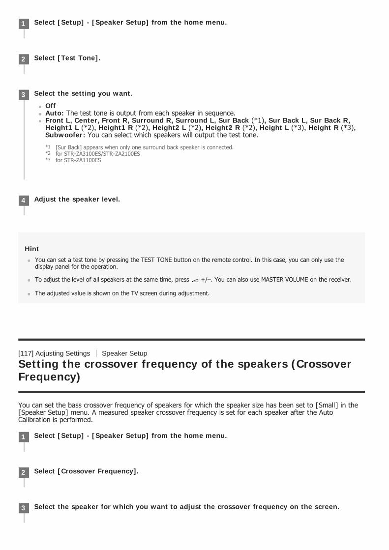
HintYou can set a test tone by pressing the TEST TONE button on the remote control. In this case, you can only use thedisplay panel for the operation.
To adjust the level of all speakers at the same time, press +/–. You can also use MASTER VOLUME on the receiver.
The adjusted value is shown on the TV screen during adjustment.
[117] Adjusting Settings Speaker Setup
Setting the crossover frequency of the speakers (CrossoverFrequency)
You can set the bass crossover frequency of speakers for which the speaker size has been set to [Small] in the[Speaker Setup] menu. A measured speaker crossover frequency is set for each speaker after the AutoCalibration is performed.
Select [Setup] - [Speaker Setup] from the home menu.1
Select [Test Tone].2
Select the setting you want.
OffAuto: The test tone is output from each speaker in sequence.Front L, Center, Front R, Surround R, Surround L, Sur Back (*1), Sur Back L, Sur Back R,Height1 L (*2), Height1 R (*2), Height2 L (*2), Height2 R (*2), Height L (*3), Height R (*3),Subwoofer: You can select which speakers will output the test tone.
3
[Sur Back] appears when only one surround back speaker is connected.*1for STR-ZA3100ES/STR-ZA2100ES*2for STR-ZA1100ES*3
Adjust the speaker level.4
Select [Setup] - [Speaker Setup] from the home menu.1
Select [Crossover Frequency].2
Select the speaker for which you want to adjust the crossover frequency on the screen.3
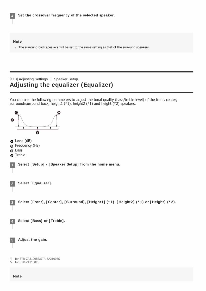
NoteThe surround back speakers will be set to the same setting as that of the surround speakers.
[118] Adjusting Settings Speaker Setup
Adjusting the equalizer (Equalizer)
You can use the following parameters to adjust the tonal quality (bass/treble level) of the front, center,surround/surround back, height1 (*1), height2 (*1) and height (*2) speakers.
Level (dB) Frequency (Hz) Bass Treble
Note
Set the crossover frequency of the selected speaker.4
Select [Setup] - [Speaker Setup] from the home menu.1
Select [Equalizer].2
Select [Front], [Center], [Surround], [Height1] (*1), [Height2] (*1) or [Height] (*2).3
Select [Bass] or [Treble].4
Adjust the gain.5
for STR-ZA3100ES/STR-ZA2100ES*1for STR-ZA1100ES*2
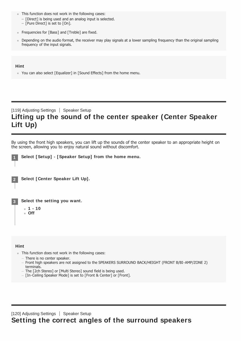
This function does not work in the following cases:[Direct] is being used and an analog input is selected.[Pure Direct] is set to [On].
Frequencies for [Bass] and [Treble] are fixed.
Depending on the audio format, the receiver may play signals at a lower sampling frequency than the original samplingfrequency of the input signals.
HintYou can also select [Equalizer] in [Sound Effects] from the home menu.
[119] Adjusting Settings Speaker Setup
Lifting up the sound of the center speaker (Center SpeakerLift Up)
By using the front high speakers, you can lift up the sounds of the center speaker to an appropriate height onthe screen, allowing you to enjoy natural sound without discomfort.
HintThis function does not work in the following cases:
There is no center speaker.Front high speakers are not assigned to the SPEAKERS SURROUND BACK/HEIGHT (FRONT B/BI-AMP/ZONE 2)terminals.The [2ch Stereo] or [Multi Stereo] sound field is being used.[In-Ceiling Speaker Mode] is set to [Front & Center] or [Front].
[120] Adjusting Settings Speaker Setup
Setting the correct angles of the surround speakers
Select [Setup] - [Speaker Setup] from the home menu.1
Select [Center Speaker Lift Up].2
Select the setting you want.
1 - 10Off
3

(Surround Speaker Position)
You can set the correct angles of the surround speakers for the Speaker Relocation function.
NoteThis function does not work when there are no surround speakers.
[121] Adjusting Settings Speaker Setup
Calibrating speaker positioning (Speaker Relocation)
You can calibrate speaker positioning (configuration angle of each speaker from the measurement position) toimprove the surround effect.
Select [Setup] - [Speaker Setup] from the home menu.1
Select [Surround Speaker Position].2
Select the setting according to the angle of the surround speaker positions.
Front: When the surround speakers are placed at less than 90° (forward from your listening position).Back: When the surround speakers are placed at more than 90° (backward from your listeningposition).
3
Select [Setup] - [Speaker Setup] from the home menu.1
Select [Speaker Relocation].2
Select the setting you want.
Type A: Places surround back speakers on the back wall in addition to those speakers inRecommendation ITU-R for 5.1 channel speaker placement.
3

NoteThis function does not work in the following cases.
[Direct] is being used and an analog input is selected.There are no surround back speakers and [Surround Speaker Position] is set to [Front].When [In-Ceiling Speaker Mode] is set to [Front & Center] or [Front].
Perform Auto Calibration before you use this function.
[122] Adjusting Settings Speaker Setup
Setting the height from the floor to the ceiling speakers(Ceiling Height)
You can set the height from the floor to the ceiling speakers. The In-Ceiling Speaker Mode function works betterby configuring this setting and performing Auto Calibration.
Type B: Places four surround speakers at virtually identical angles, according to Recommendation ITU-R for 7.1 channel speaker placement.
Off: Speaker positioning is not relocated.
Select [Setup] - [Speaker Setup] from the home menu.1
[123] Adjusting Settings Speaker Setup
Selecting the unit of measurement (Distance Unit)
You can select the unit of measurement for setting distances.
[124] Adjusting Settings Network Setup
Setting up a network (Internet Setup)
You can set up a wired LAN connection by the following procedure.
Select [Ceiling Height].2
Adjust the height.3
Select [Setup] - [Speaker Setup] from the home menu.1
Select [Distance Unit].2
Select the setting you want.
meter: The distance is displayed in meters.feet: The distance is displayed in feet.
3
Select [Setup] - [Network Setup] from the home menu.1
Select [Internet Setup].2
Select [Auto].3
Select [OK].4
If using a fixed IP address
Select [Manual] in step 3. The IP address input display appears on the TV screen.Enter the value for [IP Address] using the on-screen keyboard. Press / / / and to select thecharacters one by one, then select [Enter] to confirm the values.Enter the values for [Subnet Mask], [Default Gateway], [Primary DNS] and [Secondary DNS], then select [Next].
HintSee [Information] when checking the network settings.
[125] Adjusting Settings Network Setup
Checking the network information (Information)
You can check the various settings on the network.
[126] Adjusting Settings Network Setup
Enabling the network function even when this receiver is instandby mode (Network Standby)
The receiver starts connecting to the network. For details, refer to the messages that appear on the TVscreen.
Select [Setup] - [Network Setup] from the home menu.1
Select [Information].
You can check the settings (*) for [Connection Status], [Internet Access], [IP Address Setting], [IPAddress], [Subnet Mask], [Default Gateway], [DNS Settings], [Primary DNS], [Secondary DNS] and [MACAddress].
2
The setting items during setup differ depending on the network environment and connection type.*
Select [Setup] - [Network Setup] from the home menu.1
Select [Network Standby].2
Set to [On] or [Off].
NoteWhen the receiver is in standby mode, the (power) indicator on the front panel lights up in amber if [NetworkStandby] is set to [On].
The top of the cabinet may become hot. This is because part of the circuit(s) inside the receiver is(are) still turned on,and is not a malfunction.
[127] Adjusting Settings Network Setup
Enjoying Hi-Fi System sound (Music Connect)
You can configure settings to enable the receiver to link with a Hi-Fi System device.
NoteFor details on how to configure settings for this function, consult your nearest Sony dealer.
On: The network function works even when the receiver is in standby mode, and the receiver resumesoperation when controlled over the network.Off: The network function turns off when the receiver is in standby mode. The receiver takes more timeto resumes operation when powered on again.
3
Select [Setup] - [Network Setup] from the home menu.1
Select [Music Connect].2
Select the setting you want.
Device 1
Connected Device: Select the connected device to enable the function. Select [Remove ConnectedDevice] to disable the function.Input for Music Connect 1: Select the input to link with.Preset Volume: Preset the volume level.Output Zone: Select the zone to which you want to output sound.
Device 2
Connected Device: Select the connected device to enable the function. Select [Remove ConnectedDevice] to disable the function.Input for Music Connect 2: Select the input to link with.Preset Volume: Preset the volume level.Output Zone: Select the zone to which you want to output sound.
3
[128] Adjusting Settings Audio Setup
Playing audio signals with high-quality sound (Digital LegatoLinear (D.L.L.))
The D.L.L. function is a technology developed by Sony that allows low-quality digital and analog audio signals tobe played with high-quality sound.
NoteThis function works when [2ch Stereo], [Direct], [A.F.D.] or [Multi Stereo] is selected. However, this function does notwork in the following cases:
The [In-Ceiling Speaker Mode] function is being used.[FM TUNER] or [AM TUNER] is selected as the input.Linear PCM signals with a sampling frequency other than 44.1 kHz are being received.Dolby Digital Plus, Dolby TrueHD, Dolby Atmos, DTS 96/24, DTS-ES Matrix 6.1, DTS-HD Master Audio, DTS-HD HighResolution Audio, DTS:X, or DTS:X Master Audio signals are being received.When [Zone2 Power] is set to [On] (depending on the Zone 2 or HDMI settings).
[129] Adjusting Settings Audio Setup
Enjoying clear and dynamic sound at a low volume (SoundOptimizer)
You can enjoy clear and dynamic sound at low volume levels using the Sound Optimizer function. After Auto Calibration is performed, the sound level is optimized to suit your environment.
Select [Setup] - [Audio Setup] from the home menu.1
Select [Digital Legato Linear].2
Select the setting you want.
Auto 1: This function is available for lossy compression audio formats and analog audio signals.Auto 2: This function is available for Linear PCM signals, as well as lossy compression audio formatsand analog audio signals.Off
3
Select [Sound Effects] - [Sound Optimizer] from the home menu.1
Select the setting you want.
Normal: Adjusts for the reference level of a movie.
2

NoteThis function does not work in the following cases:
[Direct] is being used and an analog input is selected.[Pure Direct] is set to [On].
The receiver may play signals at a lower sampling frequency than the actual sampling frequency of the input signals,depending on the audio format.
HintYou can also select [Sound Optimizer] in the [Audio Setup] menu.
[130] Adjusting Settings Audio Setup
Selecting a sound field (Sound Field)
You can select from a variety of sound field modes according to speaker connections or input sources.
NoteThe sound fields for movie may not work, depending on the input or the speaker pattern you select, or with audioformats.
The receiver may play signals at a lower sampling frequency than the actual sampling frequency of the input signals,depending on the audio format.
Some speakers or the subwoofer may not output sound, depending on the sound field setting.
If there is any noise present, the noise may be different, depending on the sound field you select.
Hint
Low: Adjusts for a CD or other software whose average sound pressure level is processed highly.Off
Select [Setup] - [Audio Setup] from the home menu.1
Select [Sound Field].2
Select the sound field you want.
For details on each sound field, see “Selectable sound fields and their effects.”
3

You can also select [Sound Field] in [Sound Effects] from the home menu.
You can also use 2CH/DIRECT, A.F.D., MOVIE or MULTI ST. on the remote control or the receiver to select a sound field.
[131] Adjusting Settings Audio Setup
Enjoying more natural sound with speakers installed in theceiling (In-Ceiling Speaker Mode)
Set whether or not to use In-Ceiling Speaker Mode with the current input. In a setup where the front and center speakers are installed in the ceiling, lowering the audio output position tothe screen height allows you to enjoy a more natural experience.
NoteThis function does not work in the following cases:
[Direct] is being used and an analog input is selected.Dolby Atmos enabled speakers are used.Dolby Atmos is being decoded.[Pure Direct] is set to [On].
This function may not work depending on the audio format.
The receiver may play signals at a lower sampling frequency than the actual sampling frequency of the input signalsdepending on the audio format.
HintYou can also switch this function on/off for each input on the Input Setup screen.
You can also select [In-Ceiling Speaker Mode] in [Sound Effects] from the home menu.
You can also switch the function on/off by pressing IN-CEILING SP on the remote control or the receiver.
To obtain optimal effects in the listening environment, configure the [Ceiling Height] setting and perform AutoCalibration.
Select [Setup] - [Audio Setup] from the home menu.1
Select [In-Ceiling Speaker Mode].2
Select the setting you want.
Front & Center: Lowers the audio output position for both the front and center speakers installed inceiling to the screen height.Front: Lowers the audio output position for the front speakers installed in ceiling to the screen height.Off: Does not activate this function.
3
[132] Adjusting Settings Audio Setup
Enjoying high-fidelity sound (Pure Direct)
You can enjoy higher-fidelity sound from all inputs using the Pure Direct function. When the Pure Direct functionis on, the display panel lights off to suppress noise that affects sound quality.
Canceling Pure Direct
The Pure Direct function will be canceled when you perform the following:
Select [Off] in step 2.Press PURE DIRECT.Change the sound field.Change the scene setting on the TV (Scene Select).Change the setting of [Equalizer], [Sound Optimizer], [Dynamic Range Compressor] or [In-Ceiling SpeakerMode].
Note[Equalizer], [Sound Optimizer], [Dynamic Range Compressor] and [In-Ceiling Speaker Mode] do not work when thePure Direct function is selected.
HintYou can also use PURE DIRECT to turn the Pure Direct function on or off.
You can also select [Pure Direct] in the [Audio Setup] menu.
[133] Adjusting Settings Audio Setup
Setting the low-pass filter for the subwoofer output(Subwoofer Low Pass Filter)
You can turn the low-pass filter for the subwoofer output on or off. You can set the function for each input towhich an audio input jack is assigned independently. Turn the function on if you connect a subwoofer withoutthe crossover frequency function.
Select [Sound Effects] - [Pure Direct] from the home menu.1
Select [On].2
Select [Setup] - [Audio Setup] from the home menu.1
NoteThis function does not work when [Direct] is being used and an analog input is selected.
[134] Adjusting Settings Audio Setup
Synchronizing audio with video output (A/V Sync)
You can delay the output of audio to minimize the time gap between audio output and a visual display.This function is useful when using a large LCD or plasma monitor or a projector. You can set the function foreach input independently.
NoteThe receiver may play signals at a lower sampling frequency than the actual sampling frequency of the input signals,depending on the audio format.
[135] Adjusting Settings Audio Setup
Selecting the language of digital broadcasts (Dual Mono)
Select [Subwoofer Low Pass Filter].2
Select the setting you want.
On: Always activates the low-pass filter with a cutoff frequency of 120 Hz.Off: Does not activate the low-pass filter.
3
Select [Setup] - [Audio Setup] from the home menu.1
Select [A/V Sync].2
Select the setting you want.
HDMI Auto: The time gap between the audio output and visual display of a monitor connected via anHDMI connection will be adjusted automatically. This function is available only when the monitorsupports the A/V Sync function.0 ms – 300 ms: You can adjust the delay from 0 ms to 300 ms in 10 ms intervals.
3

You can select the language you want when listening to a digital broadcast with dual audio. This function onlyworks for Dolby Digital sources.
[136] Adjusting Settings Audio Setup
Compressing the dynamic range (Dynamic RangeCompressor)
You can compress the dynamic range of the soundtrack. This may be useful when you want to watch movies ata low volume late at night, etc.This function only works for Dolby Digital and Dolby TrueHD sources.
NoteThis function does not work when [Pure Direct] is set to [On].
Select [Setup] - [Audio Setup] from the home menu.1
Select [Dual Mono].2
Select the setting you want.
Main: Sound in the main language will be output.Sub: Sound in the sub language will be output.Main/Sub: Sound in the main language will be output through the front left speaker and sound in thesub language will be output through the front right speaker simultaneously.
3
Select [Setup] - [Audio Setup] from the home menu.1
Select [Dynamic Range Compressor].2
Select the setting you want.
Auto: The dynamic range is compressed automatically when there is a flag in the sound source thatrecommends using the Dynamic Range Compressor function.On: The dynamic range is compressed as intended by the recording engineer.Off
3
[137] Adjusting Settings Audio Setup
Switching the mode of the DTS decoder (Neural:X)
You can switch the DTS decoder to “Direct Mode” or “Non-Direct Mode.”When in “Direct Mode,” the audio is extracted and reproduced as closely as possible to what the content creatorintended. When in “Non-Direct Mode,” the audio is extracted and adapted to fit as closely as possible to thespeaker layout of the playback system (regardless of the source configuration). This function only works whenthe DTS stream is input.
NoteYou cannot set this function to [Off] when [Neural:X] is selected.
You cannot set this function to [On] in the following cases:[2ch Stereo], [Direct] or [Dolby Surround] is selected.[Pure Direct] is set to [On].
[138] Adjusting Settings HDMI Setup
Up-converting video signals to 4K (4K Scaling)
You can up-convert video signals to 4K and output them through the HDMI OUT A jack of the receiver.
Select [Setup] - [Audio Setup] from the home menu.1
Select [Neural:X].2
Select the setting you want.
On: The DTS decoder is switched to “Non-Direct Mode.”Off: The DTS decoder is switched to “Direct Mode.”
3
Select [Setup] - [HDMI Setup] from the home menu.1
Select [4K Scaling].2
Select the setting you want.
Auto: Enables video scaling control of 4K HDMI output automatically if you connect a 4K-compatibleTV.Off: Only upscales video signals from VIDEO IN, COMPONENT VIDEO IN jacks up to 1080p.
3

NoteThis function works only when video signals from the VIDEO IN, COMPONENT VIDEO IN, or HDMI IN jacks are beingreceived. HDMI video input signals must be [email protected]/24 Hz.
The HDMI OUT B (ZONE 2) jack does not support 4K Scaling.
When [4K Scaling] is set to [Auto] and the HDMI OUTPUT setting is set to [HDMI OUT A+B], the options menus, thecurrent volume and the input name are not displayed on the screen of the TV connected to the HDMI OUT B (ZONE 2)jack.
[139] Adjusting Settings HDMI Setup
Controlling HDMI devices (Control for HDMI)
You can turn the Control for HDMI function on or off. For details, see “Preparing for “BRAVIA” Sync.”
NoteWhen you set [Control for HDMI] to [On], [Audio Out] may be changed automatically.
When the receiver is in standby mode, the (power) indicator on the front panel lights up in amber if [Control forHDMI] is set to [On].
This function is enabled only when [HDMI Out B Mode] is set to [Main].
[140] Adjusting Settings HDMI Setup
Turning off the receiver and connected devicessimultaneously with the TV (System Power Off function)(Standby Linked to TV)
Select [Setup] - [HDMI Setup] from the home menu.1
Select [Control for HDMI].2
Select the setting you want.
OnOff
3
You can turn off the receiver and the connected device automatically when you turn off the TV.
NoteThis setting is valid when [Control for HDMI] is set to [On].
The connected device may not turn off depending on the status of the device.
System Power Off function may work with devices other than those manufactured by Sony, but operation is notguaranteed.
[141] Adjusting Settings HDMI Setup
Enjoying sound of an ARC compatible TV (Audio ReturnChannel)
If your TV supports the Audio Return Channel (ARC) function, set the receiver by the following procedure tooutput the sound of the TV from the speakers connected to the receiver.
Select [Setup] - [HDMI Setup] from the home menu.1
Select [Standby Linked to TV].2
Select the setting you want.
Auto: If either of the following inputs is selected on the receiver, the receiver will turn off when the TVis turned off:
[TV]An input assigned with either [HDMI], [COMPONENT] or [COMPOSITE] for video using [InputAssign]An input assigned with [HDMI] for audio using [Input Assign]
On: The receiver will turn off when the TV is turned off regardless of the input of the receiver.Off: The power of the receiver does not turn off when the TV is turned off, regardless of the input ofthe receiver.
3
Select [Setup] - [HDMI Setup] from the home menu.1
Select [Audio Return Channel].2
Select the setting you want.
Standard: The sound of the TV connected to the receiver via the HDMI OUT A jack is output from thereceiver when TV input is selected.
3
If you connect to a TV that is not compatible with the Audio Return Channel (ARC)function or you want to select an audio signal using a cable other than an HDMI cable(e.g. via an optical digital cable or an audio cable)
Select [Setup] - [Input Setup] - [Input Mode] and switch the audio input mode.
NoteBe sure to turn off the volume of the TV or activate the muting function of the TV.
If your TV does not support the System Audio Control function, set [Audio Out] to [TV + AMP] in the [HDMI Setup]menu to output the sound of the TV from the TV speaker and the speakers connected to the receiver.
[142] Adjusting Settings HDMI Setup
Enjoying content of a connected device without turning onthe receiver (Standby Through)
You can output HDMI signals to the TV even when the receiver is in standby mode.
NoteWhen the receiver is in standby mode, the (power) indicator on the front panel lights up in amber if [StandbyThrough] is set to [On] or [Auto].
The top of the cabinet may become hot. This is because part of the circuit(s) inside the receiver is(are) still turned on,and is not a malfunction.
When [Auto] is selected, it may take a little more time for the image and sound to be output to the TV than when [On]
Off: The sound of the TV connected to the receiver via the HDMI OUT A jack is not output from thereceiver even when TV input is selected.
Select [Setup] - [HDMI Setup] from the home menu.1
Select [Standby Through].2
Select the setting you want.
Auto: The receiver outputs HDMI signals to the TV from the HDMI OUT A jack when the TV is turnedon while the receiver is in the standby mode. Sony recommends this setting if you are using a “BRAVIA” Sync-compatible TV manufactured by Sony.This setting saves power in the standby mode compared to the [On] setting.On: The receiver continuously outputs HDMI signals from the HDMI OUT A jack when in standby mode.Off: The receiver does not output HDMI signals when in standby mode. This setting saves power in thestandby mode compared to the [On] setting.
3

is selected.
This function does not work for the HDMI OUT B (ZONE 2) jack.
[143] Adjusting Settings HDMI Setup
Setting the HDMI audio signal output of connected devices(Audio Out)
You can set the HDMI audio signal output of playback devices connected to the receiver via an HDMI connection.
NoteAudio signals are not output from the speaker of the TV when [Audio Out] is set to [AMP].
When [TV + AMP] is selected, the sound quality of the playback device depends on the sound quality of the TV, such asthe number of channels and the sampling frequency, etc. If the TV has stereo speakers, the sound output from thereceiver is in the same stereo as the TV, even when playing back multi-channel source.
When you connect the receiver to a video device (projector, etc.), sound may not be output from the receiver. In thiscase, select [AMP].
[144] Adjusting Settings HDMI Setup
Setting the Zone 2 HDMI audio output of connected devices(Zone2 Audio Out)
You can set the Zone 2 HDMI audio signal output for playback devices connected to the receiver via an HDMIconnection.
Select [Setup] - [HDMI Setup] from the home menu.1
Select [Audio Out].2
Select the setting you want.
AMP: HDMI audio signals from playback devices are only output to the speakers connected to thereceiver. Multi-channel sound can be played back as it is.TV + AMP: The sound is output from the speaker of the TV and the speakers connected to thereceiver.
3
Select [Setup] - [HDMI Setup] from the home menu.1
NoteYou can only configure this setting when [HDMI Out B Mode] is set to [Zone2].
When a video device (projector, etc.) is connected to the HDMI OUT B (ZONE 2) jack, sound may not be output from thereceiver. In this case, set [Zone2 Audio Out] to [AMP].
When a TV which does not support audio content protection is connected to the HDMI OUT B (ZONE 2) jack, specificaudio may not be output from the receiver. In this case, set [Zone2 Audio Out] to [AMP].
When [Zone2 Audio Out] is set to [Zone2 TV + AMP] or [AMP], audio signals will be downmixed. The followingrestrictions apply to downmixing.
If you change the sound field or speaker settings in the main zone while the input for Zone 2 is set to SOURCE or thesame input is selected in the main zone and Zone 2, the sound may also be momentarily interrupted in Zone 2.The D.L.L. function does not work in the main zone.The volume level of sound from the SPEAKERS SURROUND BACK/HEIGHT (FRONT B/BI-AMP/ZONE 2) terminals andthe HDMI OUT B (ZONE 2) jack may be different from sound that is not downmixed.
No sound will be output to Zone 2 if you play a DTS-CD with different HDMI inputs selected in the main zone and Zone2.
You cannot remedy the time gap between video output on the TV connected to the HDMI OUT B (ZONE 2) jack andaudio output from the speaker connected to the SPEAKERS SURROUND BACK/HEIGHT (FRONT B/BI-AMP/ZONE 2)terminals using the A/V Sync function.
[145] Adjusting Settings HDMI Setup
Setting the level of the subwoofer (Subwoofer Level)
You can set the level of the subwoofer to 0 dB or +10 dB when multi-channel PCM signals are input via anHDMI connection. The level for each input to which an HDMI input jack is assigned can be set independently.
Select [Zone2 Audio Out].2
Select the setting you want.
AMP: Recommended setting when a TV is connected directly to the HDMI OUT B (ZONE 2) jack.Sound is output from the speakers connected to the receiver.Sound is not output from the TV speakers.
Zone2 TV + AMP: Recommended setting when a TV is connected directly to the HDMI OUT B (ZONE2) jack.Sound is output from the TV speakers and the speakers connected to the receiver.
Zone2 AMP: Recommended setting when another amplifier is connected to the HDMI OUT B (ZONE 2)jack.Sound is output from the another amplifier connected to the HDMI OUT B (ZONE 2) jack.Sound is not output from the SPEAKERS SURROUND BACK/HEIGHT (FRONT B/BI-AMP/ZONE 2)terminals and the ZONE 2 AUDIO OUT jacks.
3
Select [Setup] - [HDMI Setup] from the home menu.1
[146] Adjusting Settings HDMI Setup
Selecting the method to use the HDMI OUT B (ZONE 2) jack(HDMI Out B Mode)
You can use the HDMI OUT B (ZONE 2) jack can be used for the Zone 2 output.
NoteWhen [Zone2] is selected, the Control for HDMI function and Fast View function do not work.
When [Main] is selected, HDMI IN audio signals cannot be output to Zone 2 speakers and the PRE OUT jacks unless theinput for Zone 2 is SOURCE or the same input is selected in the main zone and Zone 2.
When [Zone2] is selected, the HDMI OUT B (ZONE 2) jack supports bandwidth up to 9 Gbps.
[147] Adjusting Settings HDMI Setup
Setting the priority for the main zone (Priority)
Lets you set the priority when you select the same input for both the main zone and Zone 2.
Select [Subwoofer Level].2
Select the setting you want.
Auto: Automatically sets the level to 0 dB or +10 dB, depending on the audio stream.+10 dB0 dB
3
Select [Setup] - [HDMI Setup] from the home menu.1
Select [HDMI Out B Mode].2
Select the setting you want.
Main: Uses the jack for the main zone output. Recommended when you enjoy TV or projector contentin only one room (main zone).Zone2: Uses the jack for the Zone 2 output. Recommended when you enjoy video and sound from adevice connected to the receiver in a zone other than the main zone (Zone 2).
3

NoteThis function is enabled only when [HDMI Out B Mode] is set to [Zone2].
[148] Adjusting Settings HDMI Setup
Speeding up the display when switching the HDMI input(Fast View)
You can set the Fast View function for the HDMI inputs.
NoteThis function is enabled only when [HDMI Out B Mode] is set to [Main].
If you select [Off], it takes more time for images to appear after switching the input. However, the sound quality isimproved because the receiver receives signals only from the selected HDMI input jack.
Select [Setup] - [HDMI Setup] from the home menu.1
Set [Priority].
Main & Zone2: You can enjoy the same input in the main zone and Zone 2. However, there may besome interference in the audio and video signals in the main zone and Zone 2.
Main Only: You can enjoy good audio and video quality in the main zone. There is no output in Zone2.
2
Select [Setup] - [HDMI Setup] from the home menu.1
Select [Fast View].2
Select the setting you want.
Auto: You can select HDMI input faster than normal selection.Off: The Fast View function is not available.
3
[149] Adjusting Settings HDMI Setup
Setting HDMI signal formats (HDMI Signal Format)
You can select the signal format so that the receiver can receive high resolution 4K signals.
NoteWhen [Enhanced format] is selected, we recommend using a Premium High Speed HDMI Cable with Ethernet thatsupports 18 Gbps.
When [Enhanced format] is selected, some devices (cable box or satellite box, Blu-ray Disc player, and DVD player) maynot work properly. In this case, select [Standard format].
If your TV has similar menu for high bandwidth video format, check the setting on the TV menu when you select[Enhanced format] on this receiver. For details on the setting of the TV menu, refer to the operating instructions of theTV.
You cannot apply the setting to the HDMI IN 6 (GAME) jack (for STR-ZA3100ES/STR-ZA2100ES only).
[150] Adjusting Settings Zone Setup
Setting up the receiver to enjoy sound in Zone 2/3 (ZoneControls)
You can set the power, input source, and volume level for Zone 2/3.
Select [Setup] - [HDMI Setup] from the home menu.1
Select [HDMI Signal Format].2
Select the HDMI input you want to apply the setting from the HDMI IN 1, 2, 3, 4 or 5 jack.3
Select the setting you want.
Standard format: If you do not receive high resolution 4K signals, select [Standard format] usually.Enhanced format: If you want to receive high resolution 4K signals, such as 4K/60p 4:4:4, 4:2:2, and4K/60p 4:2:0 10 bit, etc., select [Enhanced format].
4
Select [Setup] - [Zone Setup] from the home menu.1
Select [Zone Controls].2
[151] Adjusting Settings Zone Setup
Presetting the volume in the main zone (Main PresetVolume)
You can set the volume level to be used when the receiver is turned on.
[152] Adjusting Settings Zone Setup
Limiting the volume for the main zone (Main Max Volume)
You can limit the maximum volume level output to the main zone.
Select the item you want, then set the item.
Zone2 Power: Turns on/off the power for Zone 2.Zone2 Input: Selects the input source for Zone 2.Zone2 Volume: Adjusts the volume level for Zone 2.Zone3 Power: Turns on/off the power for Zone 3.Zone3 Input: Selects the input source for Zone 3.Zone3 Volume: Adjusts the volume level for Zone 3.
3
Select [Setup] - [Zone Setup] from the home menu.1
Select [Main Preset Volume].2
Adjust the volume level.3
Select [Setup] - [Zone Setup] from the home menu.1
Select [Main Max Volume].2
Adjust the volume level.3
[153] Adjusting Settings Zone Setup
Presetting the volume in Zone 2/3 (Zone2/3 Preset Volume)
You can set the volume level in Zone 2 or Zone 3 when turning on the receiver.
[154] Adjusting Settings Zone Setup
Limiting the volume for Zone 2/3 (Zone2/3 Max Volume)
You can limit the maximum volume level output to Zone 2 and/or Zone 3.
[155] Adjusting Settings Zone Setup
Setting the volume control for Zone 2/3 (Zone2/3 Line Out)
You can set variable or fixed volume control for the ZONE 2 AUDIO OUT/ZONE 3 AUDIO OUT jacks.
Select [Setup] - [Zone Setup] from the home menu.1
Select [Zone2 Preset Volume] or [Zone3 Preset Volume].2
Adjust the volume level.3
Select [Setup] - [Zone Setup] from the home menu.1
Select [Zone2 Max Volume] or [Zone3 Max Volume].2
Adjust the volume level.3
Select [Setup] - [Zone Setup] from the home menu.1
Select [Zone2 Line Out] or [Zone3 Line Out].2

NoteWhen [Variable] is set, the volume level is turned down by default. Turn up the volume while listening to the sound aftercompleting setup.
[156] Adjusting Settings System Setup
Selecting the language (Language)
You can select the language of messages on the screen.
NoteWhen the Control for HDMI function on both the receiver and the TV (BRAVIA TV) is turned on, the on-screen displaylanguage of the receiver is changed simultaneously when you change the language for the on-screen display of the TV.
[157] Adjusting Settings System Setup
Tuning on/off the display for the volume level or sound field(Auto Display)
You can turn on or off the information display which appears on the TV screen when the volume level or soundfield, etc., of the receiver is changed.
Select the setting you want.
Variable: Select when you cannot adjust the volume level on the amplifier in Zone 2 or Zone 3. Thevolume level of the receiver output in Zone 2 or Zone 3 will become adjustable.Fixed: Select to adjust the volume on the amplifier in Zone 2 or Zone 3. The volume level of thereceiver output in Zone 2 or Zone 3 on the receiver will be fixed.
3
Select [Setup] - [System Setup] from the home menu.1
Select [Language].2
Select the language you want.3
Select [Setup] - [System Setup] from the home menu.1

[158] Adjusting Settings System Setup
Setting standby mode (Auto Standby)
You can set the receiver to switch to standby mode automatically when you do not operate the receiver or whenno signals are input to the receiver.
NoteThis function does not work in the following cases:
[FM TUNER] or [AM TUNER] is selected as the input.The software of the receiver is being updated.
If you use the Auto Standby mode and the sleep timer at the same time, the sleep timer has priority.
[159] Adjusting Settings System Setup
Changing the volume display (Volume Display)
You can set the volume display on the TV screen and display panel.
Select [Auto Display].2
Select the setting you want.
OnOff
3
Select [Setup] - [System Setup] from the home menu.1
Select [Auto Standby].2
Select the setting you want.
On: The receiver switches to standby mode after approximately 20 minutes.Off
3

[160] Adjusting Settings System Setup
Switching the brightness of the display panel (Dimmer)
You can switch the brightness of the display panel between 3 levels.
[161] Adjusting Settings System Setup
Using the sleep timer (Sleep)
You can set the receiver to turn off automatically after a specified period of time.
Select [Setup] - [System Setup] from the home menu.1
Select [Volume Display].2
Select the setting you want.
Relative: Indicates the volume in dB.Absolute: Indicates the number of steps.
3
Select [Setup] - [System Setup] from the home menu.1
Select [Dimmer].2
Select the setting you want.
BrightDarkOff
3
Select [Setup] - [System Setup] from the home menu.1
Select [Sleep].2

HintYou can check the remaining time before the receiver turns off on the System Setup screen. Also, the remaining timeappears on the bottom right of the TV screen when it becomes 1 minute or less.
The sleep timer will be canceled if you perform the following:Update the software of the receiver.Turn the receiver on or off.
[162] Adjusting Settings System Setup
Checking the software version (Software Version)
You can check the current software version of the receiver.
[163] Adjusting Settings System Setup
Updating the software via the network (Network Update)
You can update the receiver software via the network.Connect the receiver to the Internet beforehand, and then make sure [Internet Connection] is displayed as [OK]in the [Network Information] menu.
Set specified time.
2:00:001:30:001:00:000:30:00Off
[SLEEP] lights up on the display panel of the receiver when sleep timer is being used.
3
Select [Setup] - [System Setup] from the home menu.1
Check [Software Version].2
Select [Setup] - [System Setup] from the home menu.1
Select [Network Update].2

[164] Adjusting Settings System Setup
Updating the software using the USB flash drive (USBUpdate)
You can update the receiver software using the USB flash drive.
[165] Adjusting Settings System Setup
Setting the tuner (Tuner Setup)
You can configure the FM receiving mode (*), Name Input and Preset Gain Level settings.
[166] Adjusting Settings Install Setup
Turning on control mode for maintenance (External Control)
You can set whether or not to control the receiver from external devices.
Follow the instructions on the TV screen.3
Copy the file for updating to the top level directory (just under the root directory) of the USBflash drive.
1
Connect the USB flash drive to the SETTING (USB) port of the receiver.2
Select [Setup] - [System Setup] from the home menu.3
Select [USB Update].
[UPDATING...XXX%] appears on the display panel while updating. When the update completes, receiver willrestart automatically.
4
This function only works while the [FM TUNER] input is selected.*
Select [Setup] - [Install Setup] from the home menu.1
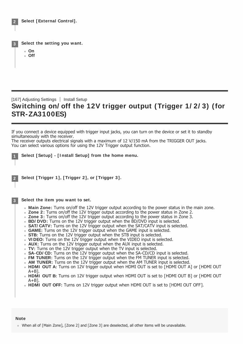
[167] Adjusting Settings Install Setup
Switching on/off the 12V trigger output (Trigger 1/2/3) (forSTR-ZA3100ES)
If you connect a device equipped with trigger input jacks, you can turn on the device or set it to standbysimultaneously with the receiver.The receiver outputs electrical signals with a maximum of 12 V/150 mA from the TRIGGER OUT jacks.You can select various options for using the 12V Trigger output function.
NoteWhen all of [Main Zone], [Zone 2] and [Zone 3] are deselected, all other items will be unavailable.
Select [External Control].2
Select the setting you want.
OnOff
3
Select [Setup] - [Install Setup] from the home menu.1
Select [Trigger 1], [Trigger 2], or [Trigger 3].2
Select the item you want to set.
Main Zone: Turns on/off the 12V trigger output according to the power status in the main zone.Zone 2: Turns on/off the 12V trigger output according to the power status in Zone 2.Zone 3: Turns on/off the 12V trigger output according to the power status in Zone 3.BD/DVD: Turns on the 12V trigger output when the BD/DVD input is selected.SAT/CATV: Turns on the 12V trigger output when the SAT/CATV input is selected.GAME: Turns on the 12V trigger output when the GAME input is selected.STB: Turns on the 12V trigger output when the STB input is selected.VIDEO: Turns on the 12V trigger output when the VIDEO input is selected.AUX: Turns on the 12V trigger output when the AUX input is selected.TV: Turns on the 12V trigger output when the TV input is selected.SA-CD/CD: Turns on the 12V trigger output when the SA-CD/CD input is selected.FM TUNER: Turns on the 12V trigger output when the FM TUNER input is selected.AM TUNER: Turns on the 12V trigger output when the AM TUNER input is selected.HDMI OUT A: Turns on 12V trigger output when HDMI OUT is set to [HDMI OUT A] or [HDMI OUTA+B].HDMI OUT B: Turns on 12V trigger output when HDMI OUT is set to [HDMI OUT B] or [HDMI OUTA+B].HDMI OUT OFF: Turns on 12V trigger output when HDMI OUT is set to [HDMI OUT OFF].
3
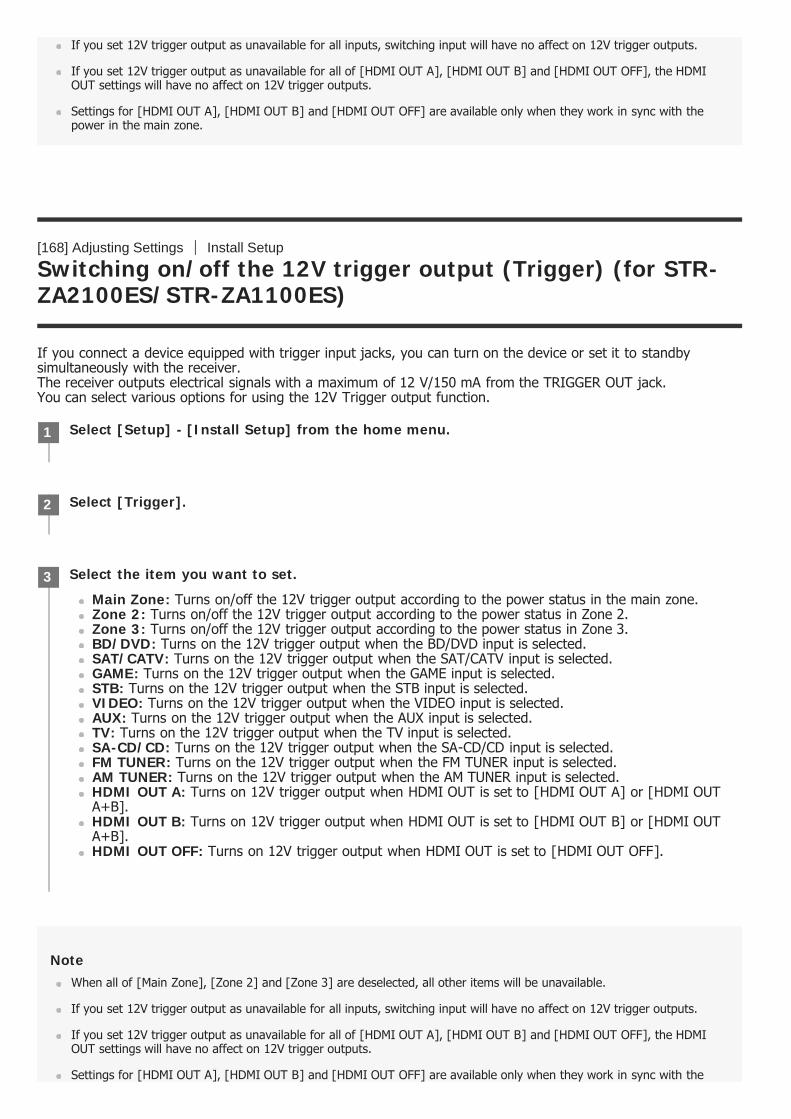
If you set 12V trigger output as unavailable for all inputs, switching input will have no affect on 12V trigger outputs.
If you set 12V trigger output as unavailable for all of [HDMI OUT A], [HDMI OUT B] and [HDMI OUT OFF], the HDMIOUT settings will have no affect on 12V trigger outputs.
Settings for [HDMI OUT A], [HDMI OUT B] and [HDMI OUT OFF] are available only when they work in sync with thepower in the main zone.
[168] Adjusting Settings Install Setup
Switching on/off the 12V trigger output (Trigger) (for STR-ZA2100ES/STR-ZA1100ES)
If you connect a device equipped with trigger input jacks, you can turn on the device or set it to standbysimultaneously with the receiver.The receiver outputs electrical signals with a maximum of 12 V/150 mA from the TRIGGER OUT jack.You can select various options for using the 12V Trigger output function.
NoteWhen all of [Main Zone], [Zone 2] and [Zone 3] are deselected, all other items will be unavailable.
If you set 12V trigger output as unavailable for all inputs, switching input will have no affect on 12V trigger outputs.
If you set 12V trigger output as unavailable for all of [HDMI OUT A], [HDMI OUT B] and [HDMI OUT OFF], the HDMIOUT settings will have no affect on 12V trigger outputs.
Settings for [HDMI OUT A], [HDMI OUT B] and [HDMI OUT OFF] are available only when they work in sync with the
Select [Setup] - [Install Setup] from the home menu.1
Select [Trigger].2
Select the item you want to set.
Main Zone: Turns on/off the 12V trigger output according to the power status in the main zone.Zone 2: Turns on/off the 12V trigger output according to the power status in Zone 2.Zone 3: Turns on/off the 12V trigger output according to the power status in Zone 3.BD/DVD: Turns on the 12V trigger output when the BD/DVD input is selected.SAT/CATV: Turns on the 12V trigger output when the SAT/CATV input is selected.GAME: Turns on the 12V trigger output when the GAME input is selected.STB: Turns on the 12V trigger output when the STB input is selected.VIDEO: Turns on the 12V trigger output when the VIDEO input is selected.AUX: Turns on the 12V trigger output when the AUX input is selected.TV: Turns on the 12V trigger output when the TV input is selected.SA-CD/CD: Turns on the 12V trigger output when the SA-CD/CD input is selected.FM TUNER: Turns on the 12V trigger output when the FM TUNER input is selected.AM TUNER: Turns on the 12V trigger output when the AM TUNER input is selected.HDMI OUT A: Turns on 12V trigger output when HDMI OUT is set to [HDMI OUT A] or [HDMI OUTA+B].HDMI OUT B: Turns on 12V trigger output when HDMI OUT is set to [HDMI OUT B] or [HDMI OUTA+B].HDMI OUT OFF: Turns on 12V trigger output when HDMI OUT is set to [HDMI OUT OFF].
3
power in the main zone.
[169] Adjusting Settings Install Setup
Displaying a test screen (Test Picture for HDMI Out A/B)
You can display a test screen with specific resolution and frame rate for HDMI OUT A and HDMI OUT B (ZONE2) jacks.
HintYou can also display a test screen with 480p/60 Hz for HDMI OUT A and HDMI OUT B jacks by pressing TEST PICTUREon the remote control.
HDMI audio signals are not output while the test screen is displayed.
[170] Adjusting Settings Install Setup
Locking settings of the receiver (Settings Lock)
You can lock the receiver settings to prevent setting values from being accidentally erased.
Select [Setup] - [Install Setup] from the home menu.1
Select [Test Picture for HDMI Out A] or [Test Picture for HDMI Out B].2
Select the setting you want.
4K/60Hz/4:4:4 (*)4K/24Hz/4:4:41080p/60Hz480p/60HzOff
3
When [HDMI Out B Mode] is set to [Zone2], this setting does not appear in [Test Picture for HDMI Out B].*
Select [Setup] - [Install Setup] from the home menu.1
Select [Settings Lock].2
HintTo set this function to [Off], press PING, AMP MENU and ENTER on the receiver at the same time.
[171] Adjusting Settings Using the menu on the display panel
Operating the receiver with the menu on the display panel
You can operate this receiver using the display panel even if the TV is not connected to the receiver or the TV isturned off.
To return to the previous display
Press or RETURN.
To exit the menu
Press AMP MENU.
NoteSome parameters and settings may appear dimmed on the display panel. This means that they are either unavailable orfixed and unchangeable.
[172] Adjusting Settings Using the menu on the display panel
Select [On].3
Press AMP MENU.
The menu is displayed on the display panel of the receiver.
1
Press / repeatedly to select the menu you want, then press .2
Press / repeatedly to select the parameter you want to adjust, then press .3
Press / repeatedly to select the setting you want, then press .4
Viewing information on the display panel
The display panel provides various information on the status of the receiver, such as the sound field.
NoteCharacters or marks in some languages may not be displayed.
[173] Adjusting Settings
Reverting to the factory default settings
You can clear all memorized settings and restore the receiver to the factory default settings by the followingprocedure. This procedure can also be used to initialize the receiver before you use it for the first time. Be sure to use the buttons on the receiver to perform this operation.
Note
Select the input for which you want to check information.1
Press DISPLAY repeatedly.
The default input name or the input name you have set is displayed on the upper line of the display panel. The lower line of the display panel will change sequentially as follows each time you press DISPLAY:currently applied sound field (*1)→stream information (*2)→default input name (*3).
When listening to FM or AM radio
The band, preset number, and preset station name (*4) or frequency are displayed on the upper line of thedisplay panel.The currently applied sound field is displayed on the lower line of the display panel.
2
[PURE DIRECT] appears on the display panel when the Pure Direct function is activated.*1Stream Information is not displayed when no signals can be found for the selected input.*2Appears only when you have set an arbitrary input name.*3Appears only when you have set an arbitrary preset station name. In this case, the preset station name and frequency are displayedalternately each time you press DISPLAY.
*4
Turn off the receiver.1
Hold down (power) on the receiver for 5 seconds.
[MEMORY CLEARING] appears on the display panel for a while, then changes to [MEMORY CLEARED!].
2
Do not turn the receiver off until [MEMORY CLEARED!] appears on the display panel.
[174] Troubleshooting Error messages
PROTECTOR
The receiver will automatically turn off after a few seconds. Check the following:
There may be an electrical surge or power failure. Unplug the AC power cord (mains lead) and then plug inthe cord again after 30 minutes.An over-current from the USB port was detected. Disconnect the USB device as prompted in the warningmessage and close the message.The receiver is covered and the ventilation holes are blocked. Remove the object covering the ventilationholes of the receiver.The impedance of the connected speakers is below the rated impedance range indicated on the back panelof the receiver. Reduce the volume level.Unplug the AC power cord (mains lead) and let the receiver cool down for 30 minutes while performing thefollowing troubleshooting:
Disconnect all of the speakers and subwoofer.Check that the speaker wires are tightly twisted on both ends.Connect the front speaker first, increase the volume level and operate the receiver for at least 30 minutesuntil it completely warms up. Then, connect each additional speaker one by one and test each additionalspeaker until you detect which speaker is causing the protection error.
After checking the above items and fixing any problems, plug in the AC power cord (mains lead) and turn onthe receiver. If the problem persists, consult your nearest Sony dealer.
[175] Troubleshooting Error messages
UPDATE FAILED
While USB Update is performed, insert a USB flash drive on which the package file for updating the receiveris saved, and then turn the receiver off and turn it on again.While Network Update is performed, press (power). If the problem persists, insert a USB flash drive onwhich the package file for updating the receiver is saved, and then press (power) again.
[176] Troubleshooting Error messages
FAN STOPPED (for STR-ZA3100ES only)
Check that the ventilation holes on the top of the receiver are not blocked.
[177] Troubleshooting Error messages
List of messages after Auto Calibration measurements
Code 31: Front speakers are not selected properly. Select the front speakers using SPEAKERS and perform the AutoCalibration again. For details on selecting the front speakers, see “4. Selecting the front speakers.”Code 32, Code 33:
Speakers were not detected or not connected properly.None of the front speakers are connected or only one front speaker is connected.Either the surround left or surround right speaker is not connected.A surround back speaker is connected only to the SPEAKERS SURROUND BACK/HEIGHT (FRONT B/BI-AMP/ZONE 2) R terminal. If connecting only one surround back speaker, connect it to the SPEAKERSSURROUND BACK/HEIGHT (FRONT B/BI-AMP/ZONE 2) L terminal.Either the Height1 left or Height1 right speaker is not connected (for STR-ZA3100ES/STR-ZA2100ES).Either the Height2 left or Height2 right speaker is not connected (for STR-ZA3100ES/STR-ZA2100ES).Either the Height left or Height right speaker is not connected (for STR-ZA1100ES).The calibration microphone is not connected. Make sure that the calibration microphone is connectedproperly and perform the Auto Calibration again.If the calibration microphone is connected properly but the error code still appears, the calibrationmicrophone cable may be damaged.
Code 34: Speakers are not placed in the proper position. Speakers or the calibration microphone on the right or leftmay be placed wrongly.Code 35:The measurement result is not match to the speaker pattern you set.Warning 40: The measurement process has been completed and a high noise level has been detected. You may be ableto achieve better results if you try the process again in a quiet environment.Warning 41, Warning 42:
The input from the calibration microphone is too large.The distance between the speaker and the calibration microphone may be too small. Set them furtherapart and perform the measurement again.
Warning 43: The distance and position of a subwoofer cannot be detected. This may be caused by noise. Try performingthe measurement in a quiet environment.Warning 44: Measurement has been completed. However the speakers are not placed in the proper position with respectto each other.NO WARNING: There is no warning information.
[178] Troubleshooting Error messages
Network features message list
Invalid XXX (*):
The entered value is incorrect or invalid.
[179] Troubleshooting General
XXX represents an IP Address, Subnet Mask, Default Gateway, Primary DNS or Secondary DNS.*
The receiver is turned off automatically.
[Auto Standby] is set to [On].The sleep timer function was activated.[PROTECTOR] was activated.[FAN STOPPED] (for STR-ZA3100ES only) was activated.
[180] Troubleshooting General
The receiver does not turn on after performing USB Updateor Network Update.
The USB Update or Network Update procedure may not have been completed.While a USB flash drive containing the package file for updating the receiver is inserted, disconnect the ACpower cord (mains lead) and connect it again.If the problem persists, consult your nearest Sony dealer.
[181] Troubleshooting General
The receiver does not turn on even when the TV is turned on.
Set [Control for HDMI] to [On] in the [HDMI Setup] menu. The TV must support the Control for HDMIfunction. For details, refer to the operating instructions of your TV.Check the speaker settings of the TV. The receiver power syncs with the speaker settings of the TV. Fordetails, refer to the operating instructions of the TV.If sound was output from the speakers of the TV last time, the receiver does not turn on even when the TVis turned on.
[182] Troubleshooting General
The receiver turns off when the TV is turned off.
Check [Standby Linked to TV] in the [HDMI Setup] menu. When the function is set to [On], the receiverautomatically turns off interlocked with the TV-power off operation, regardless of the input of the receiver.
[183] Troubleshooting General
The receiver does not turn off even when the TV is turnedoff.

Check [Standby Linked to TV] in the [HDMI Setup] menu.If you want the receiver to turn off when the TV is turned off regardless of the input of the receiver, set[Standby Linked to TV] to [On]. The TV must support the Control for HDMI function. For details, refer to theoperating instructions of your TV.Set [Control for HDMI] to [On] in the [HDMI Setup] menu. The TV must support the Control for HDMIfunction. For details, refer to the operating instructions of your TV.
[184] Troubleshooting Image
No image appears on the TV screen.
Select the appropriate input using the input buttons.Set your TV to the appropriate input mode.Assign the video input (HDMI, COMPONENT or VIDEO IN) correctly.When you are upconverting input signals using the receiver, use the same type of output signals as inputsignals.Make sure that cables are correctly and securely connected to devices.Set [HDMI Signal Format] for the selected HDMI IN jack except HDMI IN 6 (GAME) jack on STR-ZA3100ES/STR-ZA2100ES to [Standard format] in the [HDMI Setup] menu.Some playback devices need to be set up. Refer to the operating instructions supplied with each device.Be sure to use a High Speed HDMI Cable with Ethernet when you view images or listen to sound, especiallyfor 1080p, Deep Color (Deep Colour), 4K or 3D transmission. Premium High Speed HDMI Cable with Ethernetthat supports 18 Gbps is required for 4K/60p 4:4:4, 4:2:2 and 4K/60p 4:2:0 10 bit etc.The output of the HDMI video signals of the receiver may be set to [HDMI OUT OFF]. In this case, set to[HDMI OUT A], [HDMI OUT B], or [HDMI OUT A + B]. You can only select [HDMI OUT B] or [HDMI OUTA+B] when [HDMI Out B Mode] is set to [Main].If you want to play HDCP 2.2 content, connect the receiver to an HDMI input jack of a TV that supportsHDCP 2.2.
[185] Troubleshooting Image
No 3D content appears on the TV screen.
Depending on the TV or the video device, 3D content may not be displayed. Check the HDMI video formatssupported by the receiver.Be sure to use a High Speed HDMI Cable with Ethernet.
[186] Troubleshooting Image
No 4K content appears on the TV screen.
Depending on the TV or the video device, 4K content may not be displayed. Check the video capability andsettings of your TV and video device.Be sure to use a High Speed HDMI Cable with Ethernet.When you use high bandwidth video formats such as 4K/60p 4:4:4, 4:2:2 and 4K/60p 4:2:0 10 bit, werecommend you to use a Premium High Speed HDMI Cable with Ethernet that supports 18 Gbps.If your TV has similar menu for high bandwidth video format, check the setting on the TV menu when youset [HDMI Signal Format] to [Enhanced format] on this receiver. For details on the setting of the TV menu,refer to the operating instructions of the TV.

Be sure to connect the receiver to an HDMI input jack of a TV or video device that supports 4K. You have toconnect an HDMI cable to an HDMI jack that supports HDCP 2.2 when you use a playback device for 4Kresolution video content, etc.
[187] Troubleshooting Image
No image is output to the TV screen when the receiver is instandby mode.
When the receiver enters standby mode, the image from the last HDMI device selected before you turned offthe receiver is displayed. If you are enjoying content from another device, play the content on the device andperform the One-Touch Play operation, or turn on the receiver to select the HDMI device from which youwant to enjoy content.Make sure [Standby Through] is set to [Auto] or [On] in the [HDMI Setup] menu.
[188] Troubleshooting Image
The home menu does not appear on the TV screen.
If you connect the TV to the HDMI OUT B (ZONE 2) jack and [HDMI Out B Mode] is set to [Zone2] in the[HDMI Setup] menu, the home menu does not appear on the TV screen. In this case, set [HDMI Out BMode] to [Main].Press HOME to display the home menu.Check that the TV is connected correctly.The home menu may take some time to appear on the TV screen depending on the TV.
[189] Troubleshooting Image
The display panel is turned off.
Make sure [Pure Direct] is set to [Off] in the [Sound Effects] menu. When the function is set to [On], thedisplay panel is turned off.Adjust the brightness of the display panel using [Dimmer] in the [System Setup] menu.
[190] Troubleshooting Image
Image does not appear on the TV screen when the receiver isnot turned on.
Set [Control for HDMI] to [On], and then set [Standby Through] to [Auto] or [On] in the [HDMI Setup]menu.

Turn on the receiver, then select the input to which the playing device is connected.If connected to other devices than those manufactured by Sony that support the Control for HDMI function,set [Control for HDMI] to [On] in the [HDMI Setup] menu.
[191] Troubleshooting Image
When the language for the on-screen display of the TV ischanged, the on-screen display language of the receiver ischanged simultaneously.
Check [Control for HDMI] in the [HDMI Setup] menu. If [Control for HDMI] is set to [On], the on-screendisplay language of the receiver may be changed simultaneously when you change the language for the on-screen display of the TV. Select the language on the receiver again to return to the previous setting.
[192] Troubleshooting Sound
No sound or only a very low level of sound is heard, nomatter which device is selected.
Check that all connecting cables are inserted to their input/output jacks on the receiver, speakers and thedevices.Check that the receiver and all devices are turned on.Check that MASTER VOLUME on the receiver is not set to [VOLUME MIN] or [VOLUME -∞dB].Check that SPEAKERS on the receiver is not set to [SPEAKERS OFF].Press to cancel the muting function.Try pressing the input button on the remote control or on the receiver to select the device of your choice.If you want to listen to sound from the TV speaker in the main zone, set [Audio Out] to [TV + AMP] in the[HDMI Setup] menu. If you cannot play multi-channel audio source, set [AMP]. However, the sound will notbe output through the TV speaker.If you want to listen to sound from the TV speaker in Zone 2, set [Zone2 Audio Out] to [Zone2 TV + AMP]in the [HDMI Setup] menu.Sound may be interrupted when the sampling frequency, number of channels or audio format of audiooutput signals from the playback device is switched.
[193] Troubleshooting Sound
There is severe humming or noise.
Check that the speakers and device are connected securely.Make sure that the connecting cables are not near a transformer or motor.Move your audio device away from the TV.The plugs and jacks are dirty. Wipe them with a cloth slightly moistened with alcohol.

[194] Troubleshooting Sound
No sound or only a very low level of sound is heard fromspecific speakers.
Make sure you have connected to both the L and R jacks of an analog device, as analog devices require bothL and R jack connections. Use an audio cable (not supplied).Adjust the speaker level.Check that the speaker settings are appropriate for the setup using [Auto Calibration] or [Speaker Pattern] inthe [Speaker Setup] menu. Then check that sound is output from each speaker correctly using [Test Tone]in the [Speaker Setup] menu.Check that the subwoofer is connected correctly and securely.Make sure you have turned on your subwoofer.Depending on the selected sound field, sound may not be available from the subwoofer.
[195] Troubleshooting Sound
There is no sound from a specific device.
Check that the device is correctly connected to the corresponding audio input jacks.Check that the cable(s) used for the connection is (are) fully inserted into the jacks on both the receiver andthe device.Check the Input Mode setting.Check that the device is correctly connected to the corresponding HDMI jack.The HDMI settings of some playback devices need to be configured. Refer to the operating instructionssupplied with each device.Be sure to use a High Speed HDMI Cable with Ethernet when you view images or listen to sound, especiallyfor 1080p, Deep Color (Deep Colour), 4K or 3D transmission. Premium High Speed HDMI Cable with Ethernetthat supports 18 Gbps is required for 4K/60p 4:4:4, 4:2:2 and 4K/60p 4:2:0 10 bit etc.Audio signals (format, sampling frequency, bit length, etc.) transmitted from an HDMI jack may besuppressed by the connected device. Check the setup of a device connected via an HDMI cable if the imageis poor or the sound does not come out of the device.When a connected device does not support the copyright protection technology (HDCP), the image and/orthe sound from the HDMI OUT A and HDMI OUT B (ZONE 2) jacks may be distorted or may not be output. Ifthis is the case, check the specifications of the connected device.Set the image resolution of the playback device to more than 720p/1080i to enjoy High Bitrate Audio (DTS-HD Master Audio, Dolby TrueHD, DTS:X Master Audio, Dolby Atmos).The image resolution of the playback device may need to be configured to certain settings before you canenjoy DSD and Multi Channel Linear PCM. Refer to the operating instructions of the playback device.Make sure the TV supports the System Audio Control function.If the TV does not have a System Audio Control function, set [Audio Out] in the [HDMI Setup] menu to:
[TV + AMP] if you want to listen to the sound from the TV speaker and receiver.[AMP] if you want to listen to the sound from the receiver only.
If the receiver is connected to a video device such as a projector and operated in the main zone, sound maynot be output from the receiver. In this case, set [Audio Out] to [AMP] in the [HDMI Setup] menu.If a video device such as a projector is connected to the HDMI OUT B (ZONE 2) jack and [HDMI Out BMode] is set to [Zone2], sound may not be output from the receiver. In this case, set [Zone2 Audio Out] to[AMP] in the [HDMI Setup] menu.You cannot listen to the sound of a device connected to the receiver while TV input is selected on thereceiver.
Be sure to change the input of the receiver to HDMI if you want to watch a program on a deviceconnected via HDMI connection to the receiver.Change the TV channel if you want to watch a TV broadcast.Be sure to select the correct device or input when watching a program from a device connected to theTV. Refer to the section on this operation in the operating instructions of the TV.
When using the Control for HDMI function, you cannot control connected devices using the remote control ofthe TV.

Some devices and TVs need to be set up. Refer to the operating instructions supplied with each deviceand TV.Change the input of the receiver to the HDMI input connected to the device.
Check that the selected digital audio input jack is not assigned to another input.
[196] Troubleshooting Sound
There is no sound from the TV via the HDMI OUT A jackwhen using the Audio Return Channel function.
Make sure [Audio Return Channel] is set to [Standard] in the [HDMI Setup] menu.Make sure [Input Mode] for the TV input is set to [Auto].Make sure your TV supports the Audio Return Channel (ARC) function.If your TV has multiple HDMI input jacks, make sure the receiver is connected to the one that supports theAudio Return Channel (ARC) function.Make sure your TV is connected to the HDMI OUT A jack of the receiver.Make sure the HDMI OUTPUT setting is set to [HDMI OUT A] or [HDMI OUT A+B].
[197] Troubleshooting Sound
The Dolby Atmos-compatible sound played back on the TV isnot output from the receiver.
Connect the receiver to an HDMI input jack of the TV which supports the Audio Return Channel (ARC)function, and then perform the operation described in “If you use a TV compatible with Dolby Digital Plusoutput.”
[198] Troubleshooting Sound
The left and right sound is unbalanced or reversed.
Check that the speakers and device are connected correctly and securely.Adjust the sound level parameters using the [Speaker Setup] menu.
[199] Troubleshooting Sound
Dolby Digital or DTS multi-channel sound is not reproduced.
Check that the DVD, etc. you are playing is recorded in Dolby Digital or DTS format.When connecting the DVD player, etc., to the digital input jacks of this receiver, make sure the digital audio

output setting of the connected device is available.Set [Audio Out] to [AMP] in the [HDMI Setup] menu.You can only enjoy High Bitrate Audio (DTS-HD Master Audio, Dolby TrueHD, DTS:X Master Audio, DolbyAtmos), DSD and Multi Channel Linear PCM with an HDMI connection.
[200] Troubleshooting Sound
No sound is heard from specific speakers when the receiverdecodes the DTS audio signals or performs Neural:Xprocessing.
The DTS decoder and Neural:X support the following speaker patterns. If other speaker patterns are set, nosound is output from specific speakers when the receiver decodes the DTS audio signals or performsNeural:X processing.
STR-ZA3100ES/STR-ZA2100ES
2.0, 2.13.0, 3.14.0, 4.0.4 (FH+RH), 4.1, 4.1.4 (FH+RH)5.0, 5.0.2 (FH), 5.0.4 (FH+TR), 5.0.4 (FH+RH), 5.0.4 (TF+TR), 5.0.4 (TF+RH), 5.1, 5.1.2 (FH), 5.1.4(FH+TR), 5.1.4 (FH+RH), 5.1.4 (TF+TR), 5.1.4 (TF+RH)6.0 (SB), 6.1 (SB)7.0, 7.0.2 (FH), 7.1, 7.1.2 (FH)
STR-ZA1100ES
2.0, 2.13.0, 3.14.0, 4.15.0, 5.0.2 (FH), 5.1, 5.1.2 (FH)6.0 (SB), 6.1 (SB)7.0, 7.1
[201] Troubleshooting Sound
The surround effect cannot be obtained.
Make sure you have selected a sound field for movies.[Dolby Surround] and [Neural:X] do not work when the speaker pattern is set to 2.0 or 2.1.[Neural:X] does not work with DTS audio signals that have a sampling frequency of 88.2 kHz or higher.If you connect your TV via an HDMI connection and enable the Control for HDMI function, the sound fieldautomatically switches to [Multi Stereo] when you start using the Social Viewing function on your TV.
[202] Troubleshooting Sound
A test tone is not output from the speakers.
The speaker cables may not be connected securely. Check that they are connected securely and cannot be

disconnected by pulling on them slightly.The speaker cables may have short-circuited.
[203] Troubleshooting Sound
A test tone is output from a different speaker than thespeaker displayed on the TV screen.
The speaker pattern setup is incorrect. Make sure that the speaker connections and the speaker patternmatch correctly.
[204] Troubleshooting Sound
No sound is output from the TV when the receiver is instandby mode.
When the receiver enters standby mode, the image from the last HDMI device selected before you turned offthe receiver is displayed. If you are enjoying content from another device, play the content on the device andperform the One-Touch Play operation, or turn on the receiver to select the HDMI device from which youwant to enjoy content.Make sure [Standby Through] is set to [Auto] or [On] in the [HDMI Setup] menu.
[205] Troubleshooting Tuner
The FM reception is poor.
Extend and adjust the position of the FM wire antenna (aerial) to a place where the reception conditions aregood.Place the FM wire antenna (aerial) near a window.
[206] Troubleshooting Tuner
The FM stereo reception is poor.
Set the FM station receiving mode to the monaural mode.

[207] Troubleshooting Tuner
You cannot tune to radio stations.
Check that the antennas (aerials) are connected securely. Adjust the antennas (aerials) and connect anexternal antenna (aerial) if necessary.The signal of the stations is too weak with automatic tuning. Use direct tuning.Make sure you set the tuning scale correctly (when tuning to AM stations with direct tuning).No stations have been preset or the preset stations have been cleared (when tuning by scanning presetstations is used). Preset the stations.Press DISPLAY repeatedly on the receiver so that the frequency appears on the display panel.
[208] Troubleshooting USB devices
A USB device is not recognized.
Turn off the receiver, then disconnect the USB device. Turn on the receiver again and reconnect the USBdevice.Connect a compatible USB device. USB devices are only supported when formatted with the FAT16 or FAT32file systems.The USB device does not work properly. Refer to the section on how to deal with this problem in theoperating instructions of the USB device.
[209] Troubleshooting USB devices
A USB device cannot be connected to the USB port.
The USB plug is being inserted upside down. Connect the plug in the correct orientation.
[210] Troubleshooting Network connection
An error message appears.
Check the nature of the error. See “Network features message list.”
[211] Troubleshooting Network connection
Cannot connect to the network.
Check that the LAN cable is connected to the receiver when you want to connect the receiver to the networkvia a wired LAN connection.Check the network information. If [Not Connected] appears, set up the network connection again.

[212] Troubleshooting “BRAVIA” Sync (Control for HDMI)
The Control for HDMI function does not work.
Check the HDMI connection with the receiver (refer to the supplied Startup Guide).Enable the Control for HDMI function on the TV. For details, refer to the operating instructions of the TV.Wait for a while, and then try again. If you unplug the receiver, it will take a while before the operation iscompleted. Wait for 15 seconds or longer, and then try again.Check the Control for HDMI settings on the connected device. Refer to the operating instructions of theconnected device.If you unplug the HDMI cable or change the connection, repeat the procedures of “Preparing for “BRAVIA”Sync.”Make sure your TV is connected to the HDMI OUT A jack of the receiver.Make sure the HDMI OUTPUT setting is set to [HDMI OUT A] or [HDMI OUT A+B].When [Control for HDMI] is set to [Off], “BRAVIA” Sync does not work properly, even if the device isconnected to the HDMI IN jack.Make sure the connected device supports the Control for HDMI function.Enable the Control for HDMI function on the connected device. For details, refer to the operating instructionsof the connected device.The types and number of devices that can be controlled by the “BRAVIA” Sync feature are restricted by theHDMI CEC standard as follows:
Recording devices (Blu-ray Disc recorders, DVD recorders, etc.): up to 3 devicesPlayback devices (Blu-ray Disc Player, DVD players, etc.): up to 3 devicesTuner-related devices: up to 4 devices (the receiver uses one of them for its GUI operations.)Audio system (receivers): up to 1 device (used by this receiver)
Set [Control for HDMI] to [On] in the [HDMI Setup] menu.
[213] Troubleshooting “BRAVIA” Sync (Control for HDMI)
TV sound cannot be heard from the speakers connected tothe receiver.
Make sure [Audio Return Channel] is set to [Standard] in the [HDMI Setup] menu.Make sure [Input Mode] for the TV input is set to [Auto] in the [Input Setup] menu.Make sure your TV supports the ARC function. Make sure that the HDMI input of your TV is labeled “ARC.”If your TV has multiple HDMI input jacks, make sure the receiver is connected to the one supports the ARCfunction.Make sure your TV is connected to the HDMI OUT A jack of the receiver.Make sure the HDMI OUTPUT setting is set to [HDMI OUT A] or [HDMI OUT A + B].Make sure that the optical output or audio output jack(s) of the TV is correctly connected to the TV AUDIOIN jack(s) of the receiver.
[214] Troubleshooting Remote control
The remote control does not function.
Point the remote control at the remote control sensor on the receiver.Remove any obstructions between the remote control and the receiver.Replace both of the batteries in the remote control with new ones if they are weak.
[215] Troubleshooting If the problem is not solved
Reverting to the factory default settings
You can clear all memorized settings and restore the receiver to the factory default settings by the followingprocedure. This procedure can also be used to initialize the receiver before you use it for the first time. Be sure to use the buttons on the receiver to perform this operation.
NoteDo not turn the receiver off until [MEMORY CLEARED!] appears on the display panel.
[216] Troubleshooting If the problem is not solved
Resetting sound fields to the default settings
Be sure to use the buttons on the receiver to perform this operation.
[217] Troubleshooting If the problem is not solved
Customer support websites
Turn off the receiver.1
Hold down (power) on the receiver for 5 seconds.
[MEMORY CLEARING] appears on the display panel for a while, then changes to [MEMORY CLEARED!].
2
Turn off the receiver.1
Hold down MULTI ST. and press (power) on the receiver.
[S.F. INITIALIZED!] appears on the display panel and all sound fields are reset to their default setting.
2

Refer to the following websites for the latest information on the receiver.
For customers in the USA:http://esupport.sony.com/For customers in Canada:http://esupport.sony.com/CA/For customers in Latin America:http://esupport.sony.com/LA
[218] Other Information
Trademarks
This receiver incorporates Dolby (*1) Digital Surround and the DTS (*2) Digital Surround System.
This receiver incorporates High-Definition Multimedia Interface (HDMI™) technology. The terms HDMI andHDMI High-Definition Multimedia Interface, and the HDMI Logo are trademarks or registered trademarks ofHDMI Licensing, LLC in the United States and other countries.“BRAVIA” is a trademark of Sony Corporation.“PlayStation®” is a registered trademark of Sony Computer Entertainment Inc.All other trademarks and registered trademarks are of their respective holders. In this manual, ™ and ®marks are not specified.
[219] Other Information
Software License Information
md5.c, md5.h
Copyright (C) 1991-2, RSA Data Security, Inc. Created 1991. All rights reserved.License to copy and use this software is granted provided that it is identified as the “RSA Data Security, Inc.MD5 Message-Digest Algorithm” in all material mentioning or referencing this software or this function.License is also granted to make and use derivative works provided that such works are identified as “derivedfrom the RSA Data Security, Inc. MD5 Message-Digest Algorithm” in all material mentioning or referencing thederived work.RSA Data Security, Inc. makes no representations concerning either the merchantability of this software or thesuitability of this software for any particular purpose. It is provided “as is” without express or implied warranty ofany kind.These notices must be retained in any copies of any part of this documentation and/or software.
uri.c uri.h
Copyright (c) 1990- 1993, 1996 Open Software Foundation, Inc.Copyright (c) 1989 by Hewlett-Packard Company, Palo Alto, Ca. & Digital Equipment Corporation, Maynard, Mass.Copyright (c) 1998 Microsoft.
Manufactured under license from Dolby Laboratories. Dolby, Dolby Atmos, Dolby Surround, and the double-D symbol aretrademarks of Dolby Laboratories.
*1
For DTS patents, see http://patents.dts.com. Manufactured under license from DTS, Inc. DTS, the Symbol, DTS in combinationwith the Symbol, DTS:X, and the DTS:X logo are registered trademarks or trademarks of DTS, Inc. in the United States and/orother countries. © DTS, Inc. All Rights Reserved.
*2

To anyone who acknowledges that this file is provided “AS IS” without any express or implied warranty:permission to use, copy, modify, and distribute this file for any purpose is hereby granted without fee, providedthat the above copyright notices and this notice appears in all source code copies, and that none of the namesof Open Software Foundation, Inc., Hewlett-Packard Company, Microsoft, or Digital Equipment Corporation beused in advertising or publicity pertaining to distribution of the software without specific, written priorpermission. Neither Open Software Foundation, Inc., Hewlett-Packard Company, Microsoft, nor Digital EquipmentCorporation makes any representations about the suitability of this software for any purpose.
trarcfor.c
Copyright (c) April 29, 1997 Kalle Kaukonen. All Rights Reserved.Redistribution and use in source and binary forms, with or without modification, are permitted provided that thiscopyright notice and disclaimer are retained.THIS SOFTWARE IS PROVIDED BY KALLE KAUKONEN AND CONTRIBUTORS “AS IS” AND ANY EXPRESS ORIMPLIED WARRANTIES, INCLUDING, BUT NOT LIMITED TO, THE IMPLIED WARRANTIES OF MERCHANTABILITYAND FITNESS FOR A PARTICULAR PURPOSE ARE DISCLAIMED.IN NO EVENT SHALL KALLE KAUKONEN OR CONTRIBUTORS BE LIABLE FOR ANY DIRECT, INDIRECT,INCIDENTAL, SPECIAL, EXEMPLARY, OR CONSEQUENTIAL DAMAGES (INCLUDING, BUT NOT LIMITED TO,PROCUREMENT OF SUBSTITUTE GOODS OR SERVICES; LOSS OF USE, DATA, OR PROFITS; OR BUSINESSINTERRUPTION) HOWEVER CAUSED AND ON ANY THEORY OF LIABILITY, WHETHER IN CONTRACT, STRICTLIABILITY, OR TORT (INCLUDING NEGLIGENCE OR OTHERWISE) ARISING IN ANY WAY OUT OF THE USE OFTHIS SOFTWARE, EVEN IF ADVISED OF THE POSSIBILITY OF SUCH DAMAGE.
trbignu2.c trbignum.c
Modified from OPENSSL crypto/bn/bn_**.c and crypto/dh/dh_**.cCopyright (C) 1995-1998 Eric Young ([email protected])All rights reserved.This package is an SSL implementation written by Eric Young ([email protected]).The implementation was written so as to conform with Netscapes SSL.This library is free for commercial and non-commercial use as long as the following conditions are aheared to.The following conditions pply to all code found in this distribution, be it the RC4, RSA, lhash, DES, etc., code;not just the SSL code.The SSL documentation included with this distribution is covered by the same copyright terms except that theholder is Tim Hudson ([email protected]).Copyright remains Eric Young's, and as such any Copyright notices in the code are not to be removed.If this package is used in a product, Eric Young should be given attribution as the author of the parts of thelibrary used.This can be in the form of a textual message at program startup or in documentation (online or textual) providedwith the package.Redistribution and use in source and binary forms, with or without modification, are permitted provided that thefollowing conditions are met:
THIS SOFTWARE IS PROVIDED BY ERIC YOUNG “AS IS” AND ANY EXPRESS OR IMPLIED WARRANTIES,INCLUDING, BUT NOT LIMITED TO, THE IMPLIED WARRANTIES OF MERCHANTABILITY AND FITNESS FOR APARTICULAR PURPOSE ARE DISCLAIMED.IN NO EVENT SHALL THE AUTHOR OR CONTRIBUTORS BE LIABLE FOR ANY DIRECT, INDIRECT, INCIDENTAL,SPECIAL, EXEMPLARY, OR CONSEQUENTIAL DAMAGES (INCLUDING, BUT NOT LIMITED TO, PROCUREMENT OFSUBSTITUTE GOODS OR SERVICES; LOSS OF USE, DATA, OR PROFITS; OR BUSINESS INTERRUPTION)HOWEVER CAUSED AND ON ANY THEORY OF LIABILITY, WHETHER IN CONTRACT, STRICT LIABILITY, ORTORT (INCLUDING NEGLIGENCE OR OTHERWISE) ARISING IN ANY WAY OUT OF THE USE OF THISSOFTWARE, EVEN IF ADVISED OF THE POSSIBILITY OF SUCH DAMAGE.The licence and distribution terms for any publically available version or derivative of this code cannot be
Redistributions of source code must retain the copyright notice, this list of conditions and the followingdisclaimer.
1.Redistributions in binary form must reproduce the above copyright notice, this list of conditions and thefollowing disclaimer in the documentation and/or other materials provided with the distribution.
2.All advertising materials mentioning features or use of this software must display the followingacknowledgement:“This product includes cryptographic software written by Eric Young ([email protected])”The word 'cryptographic' can be left out if the rouines from the library being used are not cryptographicrelated :-).
3.
If you include any Windows specific code (or a derivative thereof) from the apps directory (application code)you must include an acknowledgement:“This product includes software written by Tim Hudson ([email protected])”
4.
changed.i.e. this code cannot simply be copied and put under another distribution licence [including the GNU PublicLicence.]
Copyright (C) 1995, 1996, 1997, and 1998 WIDE Project.All rights reserved.Redistribution and use in source and binary forms, with or without modification, are permitted provided that thefollowing conditions are met:
THIS SOFTWARE IS PROVIDED BY THE PROJECT AND CONTRIBUTORS “AS IS” AND ANY EXPRESS OR IMPLIEDWARRANTIES, INCLUDING, BUT NOT LIMITED TO, THE IMPLIED WARRANTIES OF MERCHANTABILITY ANDFITNESS FOR A PARTICULAR PURPOSE ARE DISCLAIMED.IN NO EVENT SHALL THE PROJECT OR CONTRIBUTORS BE LIABLE FOR ANY DIRECT, INDIRECT, INCIDENTAL,SPECIAL, EXEMPLARY, OR CONSEQUENTIAL DAMAGES (INCLUDING, BUT NOT LIMITED TO, PROCUREMENT OFSUBSTITUTE GOODS OR SERVICES; LOSS OF USE, DATA, OR PROFITS; OR BUSINESS INTERRUPTION)HOWEVER CAUSED AND ON ANY THEORY OF LIABILITY, WHETHER IN CONTRACT, STRICT LIABILITY, ORTORT (INCLUDING NEGLIGENCE OR OTHERWISE) ARISING IN ANY WAY OUT OF THE USE OF THISSOFTWARE, EVEN IF ADVISED OF THE POSSIBILITY OF SUCH DAMAGE.
trblwfsh.c
$KAME: bf_enc.c,v 1.5 2000/09/18 21:21:19 itojun Exp $ crypto/bf/bf_enc.cCopyright (C) 1995-1997 Eric Young ([email protected])All rights reserved.This package is an SSL implementation written by Eric Young ([email protected]).The implementation was written so as to conform with Netscapes SSL.This library is free for commercial and non-commercial use as long as the following conditions are aheared to.The following conditions apply to all code found in this distribution, be it the RC4, RSA, lhash, DES, etc., code;not just the SSL code.The SSL documentation included with this distribution is covered by the same copyright terms except that theholder is Tim Hudson ([email protected]).Copyright remains Eric Young's, and as such any Copyright notices in the code are not to be removed.If this package is used in a product, Eric Young should be given attribution as the author of the parts of thelibrary used.This can be in the form of a textual message at program startup or in documentation (online or textual) providedwith the package.Redistribution and use in source and binary forms, with or without modification, are permitted provided that thefollowing conditions are met:
THIS SOFTWARE IS PROVIDED BY ERIC YOUNG “AS IS” AND ANY EXPRESS OR IMPLIED WARRANTIES,INCLUDING, BUT NOT LIMITED TO, THE IMPLIED WARRANTIES OF MERCHANTABILITY AND FITNESS FOR APARTICULAR PURPOSE ARE DISCLAIMED.IN NO EVENT SHALL THE AUTHOR OR CONTRIBUTORS BE LIABLE FOR ANY DIRECT, INDIRECT, INCIDENTAL,SPECIAL, EXEMPLARY, OR CONSEQUENTIAL DAMAGES (INCLUDING, BUT NOT LIMITED TO, PROCUREMENT OFSUBSTITUTE GOODS OR SERVICES; LOSS OF USE, DATA, OR PROFITS; OR BUSINESS INTERRUPTION)HOWEVER CAUSED AND ON ANY THEORY OF LIABILITY, WHETHER IN CONTRACT, STRICT LIABILITY, ORTORT (INCLUDING NEGLIGENCE OR OTHERWISE) ARISING IN ANY WAY OUT OF THE USE OF THISSOFTWARE, EVEN IF ADVISED OF THE POSSIBILITY OF SUCH DAMAGE.The licence and distribution terms for any publically available version or derivative of this code cannot be
Redistributions of source code must retain the above copyright notice, this list of conditions and the followingdisclaimer.
1.Redistributions in binary form must reproduce the above copyright notice, this list of conditions and thefollowing disclaimer in the documentation and/or other materials provided with the distribution.
2.Neither the name of the project nor the names of its contributors may be used to endorse or promoteproducts derived from this software without specific prior written permission.
3.
Redistributions of source code must retain the copyright notice, this list of conditions and the followingdisclaimer.
1.Redistributions in binary form must reproduce the above copyright notice, this list of conditions and thefollowing disclaimer in the documentation and/or other materials provided with the distribution.
2.All advertising materials mentioning features or use of this software must display the followingacknowledgement:“This product includes cryptographic software written by Eric Young ([email protected])”The word 'cryptographic' can be left out if the rouines from the library being used are not cryptographicrelated :-).
3.
If you include any Windows specific code (or a derivative thereof) from the apps directory (application code)you must include an acknowledgement:“This product includes software written by Tim Hudson ([email protected])”
4.
changed.i.e. this code cannot simply be copied and put under another distribution licence [including the GNU PublicLicence.]
trcast.c
$KAME: cast128.c,v 1.4 2000/11/06 13:58:08 itojun Exp $ heavily modified by Tomomi Suzuki<[email protected]>Copyright (C) 1997 Hideo “Sir MANMOS” MorishitaAll rights reserved.Redistribution and use in source and binary forms, with or without modification, are permitted provided that thefollowing conditions are met:
THIS SOFTWARE IS PROVIDED BY Hideo “Sir MaNMOS” Morishita “AS IS” AND ANY EXPRESS OR IMPLIEDWARRANTIES, INCLUDING, BUT NOT LIMITED TO, THE IMPLIED WARRANTIES OF MERCHANTABILITY ANDFITNESS FOR A PARTICULAR PURPOSE ARE DISCLAIMED.IN NO EVENT SHALL Hideo “Sir MaNMOS” Morishita BE LIABLE FOR ANY DIRECT, INDIRECT, INCIDENTAL,SPECIAL, EXEMPLARY, OR CONSEQUENTIAL DAMAGES (INCLUDING, BUT NOT LIMITED TO, PROCUREMENT OFSUBSTITUTE GOODS OR SERVICES; LOSS OF USE, DATA, OR PROFITS; OR BUSINESS INTERRUPTION)HOWEVER CAUSED AND ON ANY THEORY OF LIABILITY, WHETHER IN CONTRACT, STRICT LIABILITY, ORTORT (INCLUDING NEGLIGENCE OR OTHERWISE) ARISING IN ANY WAY OUT OF THE USE OF THISSOFTWARE, EVEN IF ADVISED OF THE POSSIBILITY OF SUCH DAMAGE.
trdes.c
$KAME: des_ecb.c,v 1.5 2000/11/06 13:58:08 itojun Exp $ crypto/des/ecb_enc.cCopyright (C) 1995-1996 Eric Young ([email protected])All rights reserved.This file is part of an SSL implementation written by Eric Young ([email protected]).The implementation was written so as to conform with Netscapes SSL specification.This library and applications are FREE FOR COMMERCIAL AND NON-COMMERCIAL USE as long as the followingconditions are aheared to.Copyright remains Eric Young's, and as such any Copyright notices in the code are not to be removed.If this code is used in a product, Eric Young should be given attribution as the author of the parts used.This can be in the form of a textual message at program startup or in documentation (online or textual) providedwith the package.Redistribution and use in source and binary forms, with or without modification, are permitted provided that thefollowing conditions are met:
THIS SOFTWARE IS PROVIDED BY ERIC YOUNG “AS IS” AND ANY EXPRESS OR IMPLIED WARRANTIES,INCLUDING, BUT NOT LIMITED TO, THE IMPLIED WARRANTIES OF MERCHANTABILITY AND FITNESS FOR APARTICULAR PURPOSE ARE DISCLAIMED.IN NO EVENT SHALL THE AUTHOR OR CONTRIBUTORS BE LIABLE FOR ANY DIRECT, INDIRECT, INCIDENTAL,SPECIAL, EXEMPLARY, OR CONSEQUENTIAL DAMAGES (INCLUDING, BUT NOT LIMITED TO, PROCUREMENT OFSUBSTITUTE GOODS OR SERVICES; LOSS OF USE, DATA, OR PROFITS; OR BUSINESS INTERRUPTION)HOWEVER CAUSED AND ON ANY THEORY OF LIABILITY, WHETHER IN CONTRACT, STRICT LIABILITY, ORTORT (INCLUDING NEGLIGENCE OR OTHERWISE) ARISING IN ANY WAY OUT OF THE USE OF THISSOFTWARE, EVEN IF ADVISED OF THE POSSIBILITY OF SUCH DAMAGE.The licence and distribution terms for any publically available version or derivative of this code cannot bechanged.i.e. this code cannot simply be copied and put under another distribution licence [including the GNU PublicLicence.]
Redistributions of source code must retain the above copyright notice, this list of conditions and the followingdisclaimer.
1.Redistributions in binary form must reproduce the above copyright notice, this list of conditions and thefollowing disclaimer in the documentation and/or other materials provided with the distribution.
2.
Redistributions of source code must retain the copyright notice, this list of conditions and the followingdisclaimer.
1.Redistributions in binary form must reproduce the above copyright notice, this list of conditions and thefollowing disclaimer in the documentation and/or other materials provided with the distribution.
2.All advertising materials mentioning features or use of this software must display the followingacknowledgement:This product includes software developed by Eric Young ([email protected])
3.

trdhgrp.c
Modified from OPENSSL crypto/bn/bn_**.c and crypto/dh/dh_**.cCopyright (C) 1995-1998 Eric Young ([email protected])All rights reserved.This package is an SSL implementation written by Eric Young ([email protected]).The implementation was written so as to conform with Netscapes SSL.This library is free for commercial and non-commercial use as long as the following conditions are aheared to.The following conditions apply to all code found in this distribution, be it the RC4, RSA, lhash, DES, etc., code;not just the SSL code.The SSL documentation included with this distribution is covered by the same copyright terms except that theholder is Tim Hudson ([email protected]).Copyright remains Eric Young's, and as such any Copyright notices in the code are not to be removed.If this package is used in a product, Eric Young should be given attribution as the author of the parts of thelibrary used.This can be in the form of a textual message at program startup or in documentation (online or textual) providedwith the package.Redistribution and use in source and binary forms, with or without modification, are permitted provided that thefollowing conditions are met:
THIS SOFTWARE IS PROVIDED BY ERIC YOUNG “AS IS” AND ANY EXPRESS OR IMPLIED WARRANTIES,INCLUDING, BUT NOT LIMITED TO, THE IMPLIED WARRANTIES OF MERCHANTABILITY AND FITNESS FOR APARTICULAR PURPOSE ARE DISCLAIMED.IN NO EVENT SHALL THE AUTHOR OR CONTRIBUTORS BE LIABLE FOR ANY DIRECT, INDIRECT, INCIDENTAL,SPECIAL, EXEMPLARY, OR CONSEQUENTIAL DAMAGES (INCLUDING, BUT NOT LIMITED TO, PROCUREMENT OFSUBSTITUTE GOODS OR SERVICES; LOSS OF USE, DATA, OR PROFITS; OR BUSINESS INTERRUPTION)HOWEVER CAUSED AND ON ANY THEORY OF LIABILITY, WHETHER IN CONTRACT, STRICT LIABILITY, ORTORT (INCLUDING NEGLIGENCE OR OTHERWISE) ARISING IN ANY WAY OUT OF THE USE OF THISSOFTWARE, EVEN IF ADVISED OF THE POSSIBILITY OF SUCH DAMAGE.The licence and distribution terms for any publically available version or derivative of this code cannot bechanged.i.e. this code cannot simply be copied and put under another distribution licence [including the GNU PublicLicence.]
$KAME: crypto_openssl.c, eaytest.c v 1.70 2001/09/11 14:21:12 sakane Exp $Copyright (C) 1995, 1996, 1997, and 1998 WIDE Project.All rights reserved.Redistribution and use in source and binary forms, with or without modification, are permitted provided that thefollowing conditions are met:
THIS SOFTWARE IS PROVIDED BY THE PROJECT AND CONTRIBUTORS “AS IS” AND ANY EXPRESS OR IMPLIEDWARRANTIES, INCLUDING, BUT NOT LIMITED TO, THE IMPLIED WARRANTIES OF MERCHANTABILITY ANDFITNESS FOR A PARTICULAR PURPOSE ARE DISCLAIMED.IN NO EVENT SHALL THE PROJECT OR CONTRIBUTORS BE LIABLE FOR ANY DIRECT, INDIRECT, INCIDENTAL,SPECIAL, EXEMPLARY, OR CONSEQUENTIAL DAMAGES (INCLUDING, BUT NOT LIMITED TO, PROCUREMENT OFSUBSTITUTE GOODS OR SERVICES; LOSS OF USE, DATA, OR PROFITS; OR BUSINESS INTERRUPTION)HOWEVER CAUSED AND ON ANY THEORY OF LIABILITY, WHETHER IN CONTRACT, STRICT LIABILITY, ORTORT (INCLUDING NEGLIGENCE OR OTHERWISE) ARISING IN ANY WAY OUT OF THE USE OF THISSOFTWARE, EVEN IF ADVISED OF THE POSSIBILITY OF SUCH DAMAGE.
Redistributions of source code must retain the copyright notice, this list of conditions and the followingdisclaimer.
1.Redistributions in binary form must reproduce the above copyright notice, this list of conditions and thefollowing disclaimer in the documentation and/or other materials provided with the distribution.
2.All advertising materials mentioning features or use of this software must display the followingacknowledgement:“This product includes cryptographic software written by Eric Young ([email protected])”The word 'cryptographic' can be left out if the rouines from the library being used are not cryptographicrelated :-).
3.
If you include any Windows specific code (or a derivative thereof) from the apps directory (application code)you must include an acknowledgement:“This product includes software written by Tim Hudson ([email protected])”
4.
Redistributions of source code must retain the above copyright notice, this list of conditions and the followingdisclaimer.
1.Redistributions in binary form must reproduce the above copyright notice, this list of conditions and thefollowing disclaimer in the documentation and/or other materials provided with the distribution.
2.Neither the name of the project nor the names of its contributors may be used to endorse or promoteproducts derived from this software without specific prior written permission.
3.
trdsa.c
Copyright (C) 1995-1998 Eric Young ([email protected])All rights reserved.This package is an SSL implementation written by Eric Young ([email protected]).The implementation was written so as to conform with Netscapes SSL.This library is free for commercial and non-commercial use as long as the following conditions are aheared to.The following conditions apply to all code found in this distribution, be it the RC4, RSA, lhash, DES, etc., code;not just the SSL code.The SSL documentation included with this distribution is covered by the same copyright terms except that theholder is Tim Hudson ([email protected]).Copyright remains Eric Young's, and as such any Copyright notices in the code are not to be removed.If this package is used in a product, Eric Young should be given attribution as the author of the parts of thelibrary used.This can be in the form of a textual message at program startup or in documentation (online or textual) providedwith the package.Redistribution and use in source and binary forms, with or without modification, are permitted provided that thefollowing conditions are met:
THIS SOFTWARE IS PROVIDED BY ERIC YOUNG “AS IS” AND ANY EXPRESS OR IMPLIED WARRANTIES,INCLUDING, BUT NOT LIMITED TO, THE IMPLIED WARRANTIES OF MERCHANTABILITY AND FITNESS FOR APARTICULAR PURPOSE ARE DISCLAIMED.IN NO EVENT SHALL THE AUTHOR OR CONTRIBUTORS BE LIABLE FOR ANY DIRECT, INDIRECT, INCIDENTAL,SPECIAL, EXEMPLARY, OR CONSEQUENTIAL DAMAGES (INCLUDING, BUT NOT LIMITED TO, PROCUREMENT OFSUBSTITUTE GOODS OR SERVICES; LOSS OF USE, DATA, OR PROFITS; OR BUSINESS INTERRUPTION)HOWEVER CAUSED AND ON ANY THEORY OF LIABILITY, WHETHER IN CONTRACT, STRICT LIABILITY, ORTORT (INCLUDING NEGLIGENCE OR OTHERWISE) ARISING IN ANY WAY OUT OF THE USE OF THISSOFTWARE, EVEN IF ADVISED OF THE POSSIBILITY OF SUCH DAMAGE.The licence and distribution terms for any publically available version or derivative of this code cannot bechanged.i.e. this code cannot simply be copied and put under another distribution licence [including the GNU PublicLicence.]
trespcor.c
$KAME: esp_core.c,v 1.50 2000/11/02 12:27:38 itojun Exp $Copyright (C) 1995, 1996, 1997, and 1998 WIDE Project.All rights reserved.Redistribution and use in source and binary forms, with or without modification, are permitted provided that thefollowing conditions are met:
THIS SOFTWARE IS PROVIDED BY THE PROJECT AND CONTRIBUTORS “AS IS” AND ANY EXPRESS OR IMPLIEDWARRANTIES, INCLUDING, BUT NOT LIMITED TO, THE IMPLIED WARRANTIES OF MERCHANTABILITY ANDFITNESS FOR A PARTICULAR PURPOSE ARE DISCLAIMED.IN NO EVENT SHALL THE PROJECT OR CONTRIBUTORS BE LIABLE FOR ANY DIRECT, INDIRECT, INCIDENTAL,SPECIAL, EXEMPLARY, OR CONSEQUENTIAL DAMAGES (INCLUDING, BUT NOT LIMITED TO, PROCUREMENT OFSUBSTITUTE GOODS OR SERVICES; LOSS OF USE, DATA, OR PROFITS; OR BUSINESS INTERRUPTION)HOWEVER CAUSED AND ON ANY THEORY OF LIABILITY, WHETHER IN CONTRACT, STRICT LIABILITY, OR
Redistributions of source code must retain the copyright notice, this list of conditions and the followingdisclaimer.
1.Redistributions in binary form must reproduce the above copyright notice, this list of conditions and thefollowing disclaimer in the documentation and/or other materials provided with the distribution.
2.All advertising materials mentioning features or use of this software must display the followingacknowledgement:“This product includes cryptographic software written by Eric Young ([email protected])”The word 'cryptographic' can be left out if the rouines from the library being used are not cryptographicrelated :-).
3.
If you include any Windows specific code (or a derivative thereof) from the apps directory (application code)you must include an acknowledgement:“This product includes software written by Tim Hudson ([email protected])”
4.
Redistributions of source code must retain the above copyright notice, this list of conditions and the followingdisclaimer.
1.Redistributions in binary form must reproduce the above copyright notice, this list of conditions and thefollowing disclaimer in the documentation and/or other materials provided with the distribution.
2.Neither the name of the project nor the names of its contributors may be used to endorse or promoteproducts derived from this software without specific prior written permission.
3.

TORT (INCLUDING NEGLIGENCE OR OTHERWISE) ARISING IN ANY WAY OUT OF THE USE OF THISSOFTWARE, EVEN IF ADVISED OF THE POSSIBILITY OF SUCH DAMAGE.
trmd2.c
crypto/md2/md2_dgst.cCopyright (C) 1995-1998 Eric Young ([email protected])All rights reserved.This package is an SSL implementation written by Eric Young ([email protected]).The implementation was written so as to conform with Netscapes SSL.This library is free for commercial and non-commercial use as long as the following conditions are aheared to.The following conditions apply to all code found in this distribution, be it the RC4, RSA, lhash, DES, etc., code;not just the SSL code.The SSL documentation included with this distribution is covered by the same copyright terms except that theholder is Tim Hudson ([email protected]).Copyright remains Eric Young's, and as such any Copyright notices in the code are not to be removed.If this package is used in a product, Eric Young should be given attribution as the author of the parts of thelibrary used.This can be in the form of a textual message at program startup or in documentation (online or textual) providedwith the package.Redistribution and use in source and binary forms, with or without modification, are permitted provided that thefollowing conditions are met:
THIS SOFTWARE IS PROVIDED BY ERIC YOUNG “AS IS” AND ANY EXPRESS OR IMPLIED WARRANTIES,INCLUDING, BUT NOT LIMITED TO, THE IMPLIED WARRANTIES OF MERCHANTABILITY AND FITNESS FOR APARTICULAR PURPOSE ARE DISCLAIMED.IN NO EVENT SHALL THE AUTHOR OR CONTRIBUTORS BE LIABLE FOR ANY DIRECT, INDIRECT, INCIDENTAL,SPECIAL, EXEMPLARY, OR CONSEQUENTIAL DAMAGES (INCLUDING, BUT NOT LIMITED TO, PROCUREMENT OFSUBSTITUTE GOODS OR SERVICES; LOSS OF USE, DATA, OR PROFITS; OR BUSINESS INTERRUPTION)HOWEVER CAUSED AND ON ANY THEORY OF LIABILITY, WHETHER IN CONTRACT, STRICT LIABILITY, ORTORT (INCLUDING NEGLIGENCE OR OTHERWISE) ARISING IN ANY WAY OUT OF THE USE OF THISSOFTWARE, EVEN IF ADVISED OF THE POSSIBILITY OF SUCH DAMAGE.The licence and distribution terms for any publically available version or derivative of this code cannot bechanged.i.e. this code cannot simply be copied and put under another distribution licence [including the GNU PublicLicence.]
trmd4.c
Copyright (C) 1991-2, RSA Data Security, Inc. Created 1991.All rights reserved.License to copy and use this software is granted provided that it is identified as the “RSA Data Security, Inc.MD4 Message-Digest Algorithm” in all material mentioning or referencing this software or this function.License is also granted to make and use derivative works provided that such works are identified as “derivedfrom the RSA Data Security, Inc. MD4 Message-Digest Algorithm” in all material mentioning or referencing thederived work.RSA Data Security, Inc. makes no representations concerning either the merchantability of this software or thesuitability of this software for any particular purpose. It is provided “as is” without express or implied warranty ofany kind.These notices must be retained in any copies of any part of this documentation and/or software.A.3 md4c.cMD4C.C - RSA Data Security, Inc., MD4 message-digest algorithmCopyright (C) 1990-2, RSA Data Security, Inc. All rights reserved.
Redistributions of source code must retain the copyright notice, this list of conditions and the followingdisclaimer.
1.Redistributions in binary form must reproduce the above copyright notice, this list of conditions and thefollowing disclaimer in the documentation and/or other materials provided with the distribution.
2.All advertising materials mentioning features or use of this software must display the followingacknowledgement:“This product includes cryptographic software written by Eric Young ([email protected])”The word 'cryptographic' can be left out if the rouines from the library being used are not cryptographicrelated :-).
3.
If you include any Windows specific code (or a derivative thereof) from the apps directory (application code)you must include an acknowledgement:“This product includes software written by Tim Hudson ([email protected])”
4.
License to copy and use this software is granted provided that it is identified as the “RSA Data Security, Inc.MD4 Message-Digest Algorithm” in all material mentioning or referencing this software or this function.License is also granted to make and use derivative works provided that such works are identified as “derivedfrom the RSA Data Security, Inc. MD4 Message-Digest Algorithm” in all material mentioning or referencing thederived work.RSA Data Security, Inc. makes no representations concerning either the merchantability of this software or thesuitability of this software for any particular purpose. It is provided “as is” without express or implied warranty ofany kind.These notices must be retained in any copies of any part of this documentation and/or software.
trmd5.c
Copyright (C) 1990, RSA Data Security, Inc.All rights reserved.License to copy and use this software is granted provided that it is identified as the “RSA Data Security, Inc.MD5 Message- Digest Algorithm” in all material mentioning or referencing this software or this function.License is also granted to make and use derivative works provided that such works are identified as “derivedfrom the RSA Data Security, Inc. MD5 Message-Digest Algorithm” in all material mentioning or referencing thederived work.RSA Data Security, Inc. makes no representations concerning either the merchantability of this software or thesuitability of this software for any particular purpose.It is provided “as is” without express or implied warranty of any kind.These notices must be retained in any copies of any part of this documentation and/or software.
trrc2.c
Copyright (C) 1995-1998 Eric Young ([email protected])All rights reserved.This package is an SSL implementation written by Eric Young ([email protected]).The implementation was written so as to conform with Netscapes SSL.This library is free for commercial and non-commercial use as long as the following conditions are aheared to.The following conditions apply to all code found in this distribution, be it the RC4, RSA, lhash, DES, etc., code;not just the SSL code.The SSL documentation included with this distribution is covered by the same copyright terms except that theholder is Tim Hudson ([email protected]).Copyright remains Eric Young's, and as such any Copyright notices in the code are not to be removed. If thispackage is used in a product, Eric Young should be given attribution as the author of the parts of the libraryused.This can be in the form of a textual message at program startup or in documentation (online or textual) providedwith the package.Redistribution and use in source and binary forms, with or without modification, are permitted provided that thefollowing conditions are met:
THIS SOFTWARE IS PROVIDED BY ERIC YOUNG “AS IS” AND ANY EXPRESS OR IMPLIED WARRANTIES,INCLUDING, BUT NOT LIMITED TO, THE IMPLIED WARRANTIES OF MERCHANTABILITY AND FITNESS FOR APARTICULAR PURPOSE ARE DISCLAIMED.IN NO EVENT SHALL THE AUTHOR OR CONTRIBUTORS BE LIABLE FOR ANY DIRECT, INDIRECT, INCIDENTAL,SPECIAL, EXEMPLARY, OR CONSEQUENTIAL DAMAGES (INCLUDING, BUT NOT LIMITED TO, PROCUREMENT OFSUBSTITUTE GOODS OR SERVICES; LOSS OF USE, DATA, OR PROFITS; OR BUSINESS INTERRUPTION)HOWEVER CAUSED AND ON ANY THEORY OF LIABILITY, WHETHER IN CONTRACT, STRICT LIABILITY, ORTORT (INCLUDING NEGLIGENCE OR OTHERWISE) ARISING IN ANY WAY OUT OF THE USE OF THISSOFTWARE, EVEN IF ADVISED OF THE POSSIBILITY OF SUCH DAMAGE.The licence and distribution terms for any publically available version or derivative of this code cannot be
Redistributions of source code must retain the copyright notice, this list of conditions and the followingdisclaimer.
1.Redistributions in binary form must reproduce the above copyright notice, this list of conditions and thefollowing disclaimer in the documentation and/or other materials provided with the distribution.
2.All advertising materials mentioning features or use of this software must display the followingacknowledgement:“This product includes cryptographic software written by Eric Young ([email protected])”The word 'cryptographic' can be left out if the rouines from the library being used are not cryptographicrelated :-).
3.
If you include any Windows specific code (or a derivative thereof) from the apps directory (application code)you must include an acknowledgement:“This product includes software written by Tim Hudson ([email protected])”
4.

changed.i.e. this code cannot simply be copied and put under another distribution licence [including the GNU PublicLicence.]
trrmd160.c
$OpenBSD: rmd160.c,v 1.3 2001/09/26 21:40:13 markus Exp $Copyright (c) 2001 Markus Friedl.All rights reserved.Redistribution and use in source and binary forms, with or without modification, are permitted provided that thefollowing conditions are met:
THIS SOFTWARE IS PROVIDED BY THE AUTHOR “AS IS” AND ANY EXPRESS OR IMPLIED WARRANTIES,INCLUDING, BUT NOT LIMITED TO, THE IMPLIED WARRANTIES OF MERCHANTABILITY AND FITNESS FOR APARTICULAR PURPOSE ARE DISCLAIMED.IN NO EVENT SHALL THE AUTHOR BE LIABLE FOR ANY DIRECT, INDIRECT, INCIDENTAL, SPECIAL,EXEMPLARY, OR CONSEQUENTIAL DAMAGES (INCLUDING, BUT NOT LIMITED TO, PROCUREMENT OFSUBSTITUTE GOODS OR SERVICES; LOSS OF USE, DATA, OR PROFITS; OR BUSINESS INTERRUPTION)HOWEVER CAUSED AND ON ANY THEORY OF LIABILITY, WHETHER IN CONTRACT, STRICT LIABILITY, ORTORT (INCLUDING NEGLIGENCE OR OTHERWISE) ARISING IN ANY WAY OUT OF THE USE OF THISSOFTWARE, EVEN IF ADVISED OF THE POSSIBILITY OF SUCH DAMAGE.Preneel, Bosselaers, Dobbertin, “The Cryptographic Hash Function RIPEMD-160”, RSA Laboratories, CryptoBytes,Volume 3, Number 2, Autumn 1997, ftp://ftp.rsasecurity.com/pub/cryptobytes/crypto3n2.pdf
trrsa.c
Copyright (C) 1995-1998 Eric Young ([email protected])All rights reserved.This package is an SSL implementation written by Eric Young ([email protected]).The implementation was written so as to conform with Netscapes SSL.This library is free for commercial and non-commercial use as long as the following conditions are ahearedto.The following conditions apply to all code found in this distribution, be it the RC4, ttRSA, lhash, DES, etc.,code; not just the SSL code.The SSL documentation included with this distribution is covered by the same copyright terms except that theholder is Tim Hudson ([email protected]).Copyright remains Eric Young's, and as such any Copyright notices in the code are not to be removed.If this package is used in a product, Eric Young should be given attribution as the author of the parts of thelibrary used.This can be in the form of a textual message at program startup or in documentation (online or textual) providedwith the package.Redistribution and use in source and binary forms, with or without modification, are permitted provided that thefollowing conditions are met:
THIS SOFTWARE IS PROVIDED BY ERIC YOUNG “AS IS” AND ANY EXPRESS OR IMPLIED WARRANTIES,INCLUDING, BUT NOT LIMITED TO, THE IMPLIED WARRANTIES OF MERCHANTABILITY AND FITNESS FOR APARTICULAR PURPOSE ARE DISCLAIMED.IN NO EVENT SHALL THE AUTHOR OR CONTRIBUTORS BE LIABLE FOR ANY DIRECT, INDIRECT, INCIDENTAL,SPECIAL, EXEMPLARY, OR CONSEQUENTIAL DAMAGES (INCLUDING, BUT NOT LIMITED TO, PROCUREMENT OFSUBSTITUTE GOODS OR SERVICES; LOSS OF USE, DATA, OR PROFITS; OR BUSINESS INTERRUPTION)
Redistributions of source code must retain the above copyright notice, this list of conditions and the followingdisclaimer.
1.Redistributions in binary form must reproduce the above copyright notice, this list of conditions and thefollowing disclaimer in the documentation and/or other materials provided with the distribution.
2.
Redistributions of source code must retain the copyright notice, this list of conditions and the followingdisclaimer.
1.Redistributions in binary form must reproduce the above copyright notice, this list of conditions and thefollowing disclaimer in the documentation and/or other materials provided with the distribution.
2.All advertising materials mentioning features or use of this software must display the followingacknowledgement:“This product includes cryptographic software written by Eric Young ([email protected])”The word 'cryptographic' can be left out if the rouines from the library being used are not cryptographicrelated :-).
3.
If you include any Windows specific code (or a derivative thereof) from the apps directory (application code)you must include an acknowledgement:“This product includes software written by Tim Hudson ([email protected])”
4.

HOWEVER CAUSED AND ON ANY THEORY OF LIABILITY, WHETHER IN CONTRACT, STRICT LIABILITY, ORTORT (INCLUDING NEGLIGENCE OR OTHERWISE) ARISING IN ANY WAY OUT OF THE USE OF THISSOFTWARE, EVEN IF ADVISED OF THE POSSIBILITY OF SUCH DAMAGE.The licence and distribution terms for any publically available version or derivative of this code cannot bechanged.i.e. this code cannot simply be copied and put under another distribution licence [including the GNU PublicLicence.]
trsha1.c
$KAME: sha1.c,v 1.5 2000/11/08 06:13:08 itojun Exp $Copyright (C) 1995, 1996, 1997, and 1998 WIDE Project.All rights reserved.Redistribution and use in source and binary forms, with or without modification, are permitted provided that thefollowing conditions are met:
THIS SOFTWARE IS PROVIDED BY THE PROJECT AND CONTRIBUTORS “AS IS” AND ANY EXPRESS OR IMPLIEDWARRANTIES, INCLUDING, BUT NOT LIMITED TO, THE IMPLIED WARRANTIES OF MERCHANTABILITY ANDFITNESS FOR A PARTICULAR PURPOSE ARE DISCLAIMED.IN NO EVENT SHALL THE PROJECT OR CONTRIBUTORS BE LIABLE FOR ANY DIRECT, INDIRECT, INCIDENTAL,SPECIAL, EXEMPLARY, OR CONSEQUENTIAL DAMAGES (INCLUDING, BUT NOT LIMITED TO, PROCUREMENT OFSUBSTITUTE GOODS OR SERVICES; LOSS OF USE, DATA, OR PROFITS; OR BUSINESS INTERRUPTION)HOWEVER CAUSED AND ON ANY THEORY OF LIABILITY, WHETHER IN CONTRACT, STRICT LIABILITY, ORTORT (INCLUDING NEGLIGENCE OR OTHERWISE) ARISING IN ANY WAY OUT OF THE USE OF THISSOFTWARE, EVEN IF ADVISED OF THE POSSIBILITY OF SUCH DAMAGE.FIPS pub 180-1: Secure Hash Algorithm (SHA-1) based on: http://csrc.nist.gov/fips/fip180-1.txt implemented byJun-ichiro itojun Itoh <[email protected]>sha1.c : Implementation of the Secure Hash AlgorithmSHA: NIST's Secure Hash AlgorithmThis version written November 2000 by David Ireland of DI Management Services Pty Limited <[email protected]>Adapted from code in the Python Cryptography Toolkit, version 1.0.0 by A.M. Kuchling 1995.AM Kuchling's posting:-Based on SHA code originally posted to sci.crypt by Peter Gutmann in message<[email protected]>.The original specification of SHA was found to have a weakness by NSA/NIST.This code implements the fixed version of SHA.Here's the first paragraph of Peter Gutmann's posting:The following is my SHA (FIPS 180) code updated to allow use of the “fixed” SHA, thanks to Jim Gillogly and ananonymous contributor for the information on what's changed in the new version.The fix is a simple change which involves adding a single rotate in the initial expansion function.It is unknown whether this is an optimal solution to the problem which was discovered in the SHA or whetherit's simply a bandaid which fixes the problem with a minimum of effort (for example the reengineering of a greatmany Capstone chips).
trsha2.c
$KAME: sha1.c,v 1.5 2000/11/08 06:13:08 itojun Exp $Copyright (C) 1995, 1996, 1997, and 1998 WIDE Project.All rights reserved.Redistribution and use in source and binary forms, with or without modification, are permitted provided that thefollowing conditions are met:
Redistributions of source code must retain the above copyright notice, this list of conditions and the followingdisclaimer.
1.Redistributions in binary form must reproduce the above copyright notice, this list of conditions and thefollowing disclaimer in the documentation and/or other materials provided with the distribution.
2.Neither the name of the project nor the names of its contributors may be used to endorse or promoteproducts derived from this software without specific prior written permission.
3.

THIS SOFTWARE IS PROVIDED BY THE PROJECT AND CONTRIBUTORS “AS IS” AND ANY EXPRESS OR IMPLIEDWARRANTIES, INCLUDING, BUT NOT LIMITED TO, THE IMPLIED WARRANTIES OF MERCHANTABILITY ANDFITNESS FOR A PARTICULAR PURPOSE ARE DISCLAIMED.IN NO EVENT SHALL THE PROJECT OR CONTRIBUTORS BE LIABLE FOR ANY DIRECT, INDIRECT, INCIDENTAL,SPECIAL, EXEMPLARY, OR CONSEQUENTIAL DAMAGES (INCLUDING, BUT NOT LIMITED TO, PROCUREMENT OFSUBSTITUTE GOODS OR SERVICES; LOSS OF USE, DATA, OR PROFITS; OR BUSINESS INTERRUPTION)HOWEVER CAUSED AND ON ANY THEORY OF LIABILITY, WHETHER IN CONTRACT, STRICT LIABILITY, ORTORT (INCLUDING NEGLIGENCE OR OTHERWISE) ARISING IN ANY WAY OUT OF THE USE OF THISSOFTWARE, EVEN IF ADVISED OF THE POSSIBILITY OF SUCH DAMAGE.FIPS pub 180-2: Secure Hash Standard based on: http://csrc.nist.gov/publications/fips/fips180-2/fips180-2.pdf
trsha5.c
sha512.c - implementation of SHA256, SHA384 and SHA512***** BEGIN LICENSE BLOCK *****Version: MPL 1.1/GPL 2.0/LGPL 2.1The contents of this file are subject to the Mozilla Public License Version 1.1 (the “License”); you may not usethis file except in compliance with the License. You may obtain a copy of the License athttp://www.mozilla.org/MPL/Software distributed under the License is distributed on an “AS IS” basis, WITHOUT WARRANTY OF ANY KIND,either express or implied. See the License for the specific language governing rights and limitations under theLicense.The Original Code is the Netscape security libraries.The Initial Developer of the Original Code is Netscape Communications Corporation.Portions created by the Initial Developer are Copyright (C) 2002 the Initial Developer.All Rights Reserved.Contributor(s):Alternatively, the contents of this file may be used under the terms of either the GNU General Public LicenseVersion 2 or later (the “GPL”), or the GNU Lesser General Public License Version 2.1 or later (the “LGPL”), inwhich case the provisions of the GPL or the LGPL are applicable instead of those above. If you wish to allow useof your version of this file only under the terms of either the GPL or the LGPL, and not to allow others to useyour version of this file under the terms of the MPL, indicate your decision by deleting the provisions above andreplace them with the notice and other provisions required by the GPL or the LGPL. If you do not delete theprovisions above, a recipient may use your version of this file under the terms of any one of the MPL, the GPL orthe LGPL.***** END LICENSE BLOCK ***** */FIPS pub 180-2: Secure Hash Standard based on: http://csrc.nist.gov/publications/fips/fips180-2/fips180-2.pdf
trtwofsh.c
Copyright (c) 2002 by Niels Ferguson.The author hereby grants a perpetual license to everybody to use this code for any purpose as long as thecopyright message is included in the source code of this or any derived work.Yes, this means that you, your company, your club, and anyone else can use this code anywhere you want.You can change it and distribute it under the GPL, include it in your commercial product without releasing thesource code, put it on the web, etc.The only thing you cannot do is remove my copyright message, or distribute any source code based on thisimplementation that does not include my copyright message.I appreciate a mention in the documentation or credits, but I understand if that is difficult to do.I also appreciate it if you tell me where and why you used my code.DISCLAIMER: As I'm giving away my work for free, I'm of course not going to accept any liability of any form.This code, or the Twofish cipher, might very well be flawed; you have been warned.This software is provided as-is, without any kind of warrenty or guarantee.And that is really all you can expect when you download code for free from the Internet.
trqsort.c
Copyright (c) 1992, 1993The Regents of the University of California.All rights reserved.Redistribution and use in source and binary forms, with or without modification, are permitted provided that thefollowing conditions are met:
THIS SOFTWARE IS PROVIDED BY THE REGENTS AND CONTRIBUTORS “AS IS” AND ANY EXPRESS OR IMPLIEDWARRANTIES, INCLUDING, BUT NOT LIMITED TO, THE IMPLIED WARRANTIES OF MERCHANTABILITY ANDFITNESS FOR A PARTICULAR PURPOSE ARE DISCLAIMED.IN NO EVENT SHALL THE REGENTS OR CONTRIBUTORS BE LIABLE FOR ANY DIRECT, INDIRECT, INCIDENTAL,SPECIAL, EXEMPLARY, OR CONSEQUENTIAL DAMAGES (INCLUDING, BUT NOT LIMITED TO, PROCUREMENT OFSUBSTITUTE GOODS OR SERVICES; LOSS OF USE, DATA, OR PROFITS; OR BUSINESS INTERRUPTION)HOWEVER CAUSED AND ON ANY THEORY OF LIABILITY, WHETHER IN CONTRACT, STRICT LIABILITY, ORTORT (INCLUDING NEGLIGENCE OR OTHERWISE) ARISING IN ANY WAY OUT OF THE USE OF THISSOFTWARE, EVEN IF ADVISED OF THE POSSIBILITY OF SUCH DAMAGE.
trsprnf.c
Copyright (c) 1992, 1993The Regents of the University of California.All rights reserved.Redistribution and use in source and binary forms, with or without modification, are permitted provided that thefollowing conditions are met:
THIS SOFTWARE IS PROVIDED BY THE REGENTS AND CONTRIBUTORS “AS IS” AND ANY EXPRESS OR IMPLIEDWARRANTIES, INCLUDING, BUT NOT LIMITED TO, THE IMPLIED WARRANTIES OF MERCHANTABILITY ANDFITNESS FOR A PARTICULAR PURPOSE ARE DISCLAIMED.IN NO EVENT SHALL THE REGENTS OR CONTRIBUTORS BE LIABLE FOR ANY DIRECT, INDIRECT, INCIDENTAL,SPECIAL, EXEMPLARY, OR CONSEQUENTIAL DAMAGES (INCLUDING, BUT NOT LIMITED TO, PROCUREMENT OFSUBSTITUTE GOODS OR SERVICES; LOSS OF USE, DATA, OR PROFITS; OR BUSINESS INTERRUPTION)HOWEVER CAUSED AND ON ANY THEORY OF LIABILITY, WHETHER IN CONTRACT, STRICT LIABILITY, ORTORT (INCLUDING NEGLIGENCE OR OTHERWISE) ARISING IN ANY WAY OUT OF THE USE OF THISSOFTWARE, EVEN IF ADVISED OF THE POSSIBILITY OF SUCH DAMAGE.
trsscanf.c
Copyright (c) 1992, 1993The Regents of the University of California.All rights reserved.Redistribution and use in source and binary forms, with or without modification, are permitted provided that thefollowing conditions are met:
THIS SOFTWARE IS PROVIDED BY THE REGENTS AND CONTRIBUTORS “AS IS” AND ANY EXPRESS OR IMPLIEDWARRANTIES, INCLUDING, BUT NOT LIMITED TO, THE IMPLIED WARRANTIES OF MERCHANTABILITY AND
Redistributions of source code must retain the above copyright notice, this list of conditions and the followingdisclaimer.
1.Redistributions in binary form must reproduce the above copyright notice, this list of conditions and thefollowing disclaimer in the documentation and/or other materials provided with the distribution.
2.All advertising materials mentioning features or use of this software must display the followingacknowledgement:This product includes software developed by the University of California, Berkeley and its contributors.
3.
Neither the name of the University nor the names of its contributors may be used to endorse or promoteproducts derived from this software without specific prior written permission.
4.

FITNESS FOR A PARTICULAR PURPOSE ARE DISCLAIMED.IN NO EVENT SHALL THE REGENTS OR CONTRIBUTORS BE LIABLE FOR ANY DIRECT, INDIRECT, INCIDENTAL,SPECIAL, EXEMPLARY, OR CONSEQUENTIAL DAMAGES (INCLUDING, BUT NOT LIMITED TO, PROCUREMENT OFSUBSTITUTE GOODS OR SERVICES; LOSS OF USE, DATA, OR PROFITS; OR BUSINESS INTERRUPTION)HOWEVER CAUSED AND ON ANY THEORY OF LIABILITY, WHETHER IN CONTRACT, STRICT LIABILITY, ORTORT (INCLUDING NEGLIGENCE OR OTHERWISE) ARISING IN ANY WAY OUT OF THE USE OF THISSOFTWARE, EVEN IF ADVISED OF THE POSSIBILITY OF SUCH DAMAGE.
trstrtox.c
Copyright (c) 1990, 1993The Regents of the University of California.All rights reserved.Redistribution and use in source and binary forms, with or without modification, are permitted provided that thefollowing conditions are met:
THIS SOFTWARE IS PROVIDED BY THE REGENTS AND CONTRIBUTORS “AS IS” AND ANY EXPRESS OR IMPLIEDWARRANTIES, INCLUDING, BUT NOT LIMITED TO, THE IMPLIED WARRANTIES OF MERCHANTABILITY ANDFITNESS FOR A PARTICULAR PURPOSE ARE DISCLAIMED.IN NO EVENT SHALL THE REGENTS OR CONTRIBUTORS BE LIABLE FOR ANY DIRECT, INDIRECT, INCIDENTAL,SPECIAL, EXEMPLARY, OR CONSEQUENTIAL DAMAGES (INCLUDING, BUT NOT LIMITED TO, PROCUREMENT OFSUBSTITUTE GOODS OR SERVICES; LOSS OF USE, DATA, OR PROFITS; OR BUSINESS INTERRUPTION)HOWEVER CAUSED AND ON ANY THEORY OF LIABILITY, WHETHER IN CONTRACT, STRICT LIABILITY, ORTORT (INCLUDING NEGLIGENCE OR OTHERWISE) ARISING IN ANY WAY OUT OF THE USE OF THISSOFTWARE, EVEN IF ADVISED OF THE POSSIBILITY OF SUCH DAMAGE.
trvscanf.c
Copyright (c) 1990, 1993The Regents of the University of California.All rights reserved.This code is derived from software contributed to Berkeley by Chris Torek.Redistribution and use in source and binary forms, with or without modification, are permitted provided that thefollowing conditions are met:
THIS SOFTWARE IS PROVIDED BY THE REGENTS AND CONTRIBUTORS “AS IS” AND ANY EXPRESS OR IMPLIEDWARRANTIES, INCLUDING, BUT NOT LIMITED TO, THE IMPLIED WARRANTIES OF MERCHANTABILITY ANDFITNESS FOR A PARTICULAR PURPOSE ARE DISCLAIMED.IN NO EVENT SHALL THE REGENTS OR CONTRIBUTORS BE LIABLE FOR ANY DIRECT, INDIRECT, INCIDENTAL,SPECIAL, EXEMPLARY, OR CONSEQUENTIAL DAMAGES (INCLUDING, BUT NOT LIMITED TO, PROCUREMENT OFSUBSTITUTE GOODS OR SERVICES; LOSS OF USE, DATA, OR PROFITS; OR BUSINESS INTERRUPTION)HOWEVER CAUSED AND ON ANY THEORY OF LIABILITY, WHETHER IN CONTRACT, STRICT LIABILITY, ORTORT (INCLUDING NEGLIGENCE OR OTHERWISE) ARISING IN ANY WAY OUT OF THE USE OF THISSOFTWARE, EVEN IF ADVISED OF THE POSSIBILITY OF SUCH DAMAGE.
trvsprnf.c
Redistributions of source code must retain the above copyright notice, this list of conditions and the followingdisclaimer.
1.Redistributions in binary form must reproduce the above copyright notice, this list of conditions and thefollowing disclaimer in the documentation and/or other materials provided with the distribution.
2.All advertising materials mentioning features or use of this software must display the followingacknowledgement:This product includes software developed by the University of California, Berkeley and its contributors.
3.
Neither the name of the University nor the names of its contributors may be used to endorse or promoteproducts derived from this software without specific prior written permission.
4.

Copyright (c) 1992, 1993The Regents of the University of California.All rights reserved.Redistribution and use in source and binary forms, with or without modification, are permitted provided that thefollowing conditions are met:
THIS SOFTWARE IS PROVIDED BY THE REGENTS AND CONTRIBUTORS “AS IS” AND ANY EXPRESS OR IMPLIEDWARRANTIES, INCLUDING, BUT NOT LIMITED TO, THE IMPLIED WARRANTIES OF MERCHANTABILITY ANDFITNESS FOR A PARTICULAR PURPOSE ARE DISCLAIMED.IN NO EVENT SHALL THE REGENTS OR CONTRIBUTORS BE LIABLE FOR ANY DIRECT, INDIRECT, INCIDENTAL,SPECIAL, EXEMPLARY, OR CONSEQUENTIAL DAMAGES (INCLUDING, BUT NOT LIMITED TO, PROCUREMENT OFSUBSTITUTE GOODS OR SERVICES; LOSS OF USE, DATA, OR PROFITS; OR BUSINESS INTERRUPTION)HOWEVER CAUSED AND ON ANY THEORY OF LIABILITY, WHETHER IN CONTRACT, STRICT LIABILITY, ORTORT (INCLUDING NEGLIGENCE OR OTHERWISE) ARISING IN ANY WAY OUT OF THE USE OF THISSOFTWARE, EVEN IF ADVISED OF THE POSSIBILITY OF SUCH DAMAGE.
trdeflate.c
Copyright (C) 1995-2010 Jean-loup Gailly and Mark AdlerFor conditions of distribution and use, see copyright notice in zlib.hALGORITHMThe “deflation” process depends on being able to identify portions of the input text which are identical to earlierinput (within a sliding window trailing behind the input currently being processed).The most straightforward technique turns out to be the fastest for most input files: try all possible matches andselect the longest.The key feature of this algorithm is that insertions into the string dictionary are very simple and thus fast, anddeletions are avoided completely. Insertions are performed at each input character, whereas string matches areperformed only when the previous match ends. So it is preferable to spend more time in matches to allow veryfast string insertions and avoid deletions. The matching algorithm for small strings is inspired from that of Rabin& Karp. A brute force approach is used to find longer strings when a small match has been found.A similar algorithm is used in comic (by Jan-Mark Wams) and freeze (by Leonid Broukhis).A previous version of this file used a more sophisticated algorithm (by Fiala and Greene) which is guaranteed torun in linear amortized time, but has a larger average cost, uses more memory and is patented.However the F&G algorithm may be faster for some highly redundant files if the parameter maxChainLength(described below) is too large.ACKNOWLEDGEMENTSThe idea of lazy evaluation of matches is due to Jan-Mark Wams, and I found it in 'freeze' written by LeonidBroukhis.Thanks to many people for bug reports and testing.REFERENCESDeutsch, L.P., “DEFLATE Compressed Data Format Specification”.Available in http://www.ietf.org/rfc/rfc1951.txtA description of the Rabin and Karp algorithm is given in the book “Algorithms” by R. Sedgewick, Addison-Wesley, p252.Fiala,E.R., and Greene,D.H.Data Compression with Finite Windows, Comm.ACM, 32,4 (1989) 490-595This software is provided 'as-is', without any express or implied warranty.In no event will the authors be held liable for any damages arising from the use of this software.Permission is granted to anyone to use this software for any purpose, including commercial applications, and toalter it and redistribute it freely, subject to the following restrictions:
Redistributions of source code must retain the above copyright notice, this list of conditions and the followingdisclaimer.
1.Redistributions in binary form must reproduce the above copyright notice, this list of conditions and thefollowing disclaimer in the documentation and/or other materials provided with the distribution.
2.All advertising materials mentioning features or use of this software must display the followingacknowledgement: This product includes software developed by the University of California, Berkeley and itscontributors.
3.
Neither the name of the University nor the names of its contributors may be used to endorse or promoteproducts derived from this software without specific prior written permission.
4.
The origin of this software must not be misrepresented; you must not claim that you wrote the originalsoftware. If you use this software in a product, an acknowledgment in the product documentation would beappreciated but is not required.
1.
Altered source versions must be plainly marked as such, and must not be misrepresented as being theoriginal software.
2.This notice may not be removed or altered from any source distribution.3.
Jean-loup [email protected] [email protected] data format used by the zlib library is described by RFCs (Request for Comments) 1950 to 1952 in the fileshttp://www.ietf.org/rfc/rfc1950.txt (zlib format), rfc1951.txt (deflate format) and rfc1952.txt (gzip format).
trinfback.c
Copyright (C) 1995-2009 Mark AdlerFor conditions of distribution and use, see copyright notice in zlib.hThis code is largely copied from inflate.c.Normally either infback.o or inflate.o would be linked into an application--not both.The interface with inffast.c is retained so that optimized assembler-coded versions of inflate_fast() can be usedwith either inflate.c or infback.c.This software is provided 'as-is', without any express or implied warranty.In no event will the authors be held liable for any damages arising from the use of this software.Permission is granted to anyone to use this software for any purpose, including commercial applications, and toalter it and redistribute it freely, subject to the following restrictions:
Jean-loup [email protected] [email protected] data format used by the zlib library is described by RFCs (Request for Comments) 1950 to 1952 in the fileshttp://www.ietf.org/rfc/rfc1950.txt (zlib format), rfc1951.txt (deflate format) and rfc1952.txt (gzip format).
trinffast.c
Copyright (C) 1995-2010 Mark AdlerFor conditions of distribution and use, see copyright notice in zlib.hThis software is provided 'as-is', without any express or implied warranty.In no event will the authors be held liable for any damages arising from the use of this software.Permission is granted to anyone to use this software for any purpose, including commercial applications, and toalter it and redistribute it freely, subject to the following restrictions:
Jean-loup [email protected] [email protected] data format used by the zlib library is described by RFCs (Request for Comments) 1950 to 1952 in the fileshttp://www.ietf.org/rfc/rfc1950.txt (zlib format), rfc1951.txt (deflate format) and rfc1952.txt (gzip format).
trinflate.c
Copyright (C) 1995-2010 Mark AdlerFor conditions of distribution and use, see copyright notice in zlib.hThis software is provided 'as-is', without any express or implied warranty.In no event will the authors be held liable for any damages arising from the use of this software.Permission is granted to anyone to use this software for any purpose, including commercial applications, and toalter it and redistribute it freely, subject to the following restrictions:
The origin of this software must not be misrepresented; you must not claim that you wrote the originalsoftware. If you use this software in a product, an acknowledgment in the product documentation would beappreciated but is not required.
1.
Altered source versions must be plainly marked as such, and must not be misrepresented as being theoriginal software.
2.This notice may not be removed or altered from any source distribution.3.
Jean-loup [email protected] [email protected] data format used by the zlib library is described by RFCs (Request for Comments) 1950 to 1952 in the fileshttp://www.ietf.org/rfc/rfc1950.txt (zlib format), rfc1951.txt (deflate format) and rfc1952.txt (gzip format).
trinftrees.c
Copyright (C) 1995-2010 Mark AdlerFor conditions of distribution and use, see copyright notice in zlib.hThis software is provided 'as-is', without any express or implied warranty.In no event will the authors be held liable for any damages arising from the use of this software.Permission is granted to anyone to use this software for any purpose, including commercial applications, and toalter it and redistribute it freely, subject to the following restrictions:
Jean-loup [email protected] [email protected] data format used by the zlib library is described by RFCs (Request for Comments) 1950 to 1952 in the fileshttp://www.ietf.org/rfc/rfc1950.txt (zlib format), rfc1951.txt (deflate format) and rfc1952.txt (gzip format).
trees.c
Copyright (C) 1995-2010 Jean-loup Gailly detect_data_type() function provided freely by Cosmin Truta, 2006For conditions of distribution and use, see copyright notice in zlib.hALGORITHMThe “deflation” process uses several Huffman trees. The more common source values are represented by shorterbit sequences.Each code tree is stored in a compressed form which is itself a Huffman encoding of the lengths of all the codestrings (in ascending order by source values).The actual code strings are reconstructed from the lengths in the inflate process, as described in the deflatespecification.REFERENCESDeutsch, L.P., “'Deflate' Compressed Data Format Specification”.Available in ftp.uu.net:/pub/archiving/zip/doc/deflate-1.1.docStorer, James A.Data Compression: Methods and Theory, pp. 49-50.Computer Science Press, 1988. ISBN 0-7167-8156-5.Sedgewick, R.Algorithms, p290.Addison-Wesley, 1983. ISBN 0-201-06672-6.This software is provided 'as-is', without any express or implied warranty.In no event will the authors be held liable for any damages arising from the use of this software.Permission is granted to anyone to use this software for any purpose, including commercial applications, and toalter it and redistribute it freely, subject to the following restrictions:
The origin of this software must not be misrepresented; you must not claim that you wrote the originalsoftware. If you use this software in a product, an acknowledgment in the product documentation would beappreciated but is not required.
1.
Altered source versions must be plainly marked as such, and must not be misrepresented as being theoriginal software.
2.This notice may not be removed or altered from any source distribution.3.
The origin of this software must not be misrepresented; you must not claim that you wrote the originalsoftware. If you use this software in a product, an acknowledgment in the product documentation would beappreciated but is not required.
1.
Altered source versions must be plainly marked as such, and must not be misrepresented as being theoriginal software.
2.
Jean-loup [email protected] [email protected] data format used by the zlib library is described by RFCs (Request for Comments) 1950 to 1952 in the fileshttp://www.ietf.org/rfc/rfc1950.txt (zlib format), rfc1951.txt (deflate format) and rfc1952.txt (gzip format).
trzutil.c
Copyright (C) 1995-2005, 2010 Jean-loup Gailly.For conditions of distribution and use, see copyright notice in zlib.hThis software is provided 'as-is', without any express or implied warranty.In no event will the authors be held liable for any damages arising from the use of this software.Permission is granted to anyone to use this software for any purpose, including commercial applications, and toalter it and redistribute it freely, subject to the following restrictions:
Jean-loup [email protected] [email protected] data format used by the zlib library is described by RFCs (Request for Comments) 1950 to 1952 in the fileshttp://www.ietf.org/rfc/rfc1950.txt (zlib format), rfc1951.txt (deflate format) and rfc1952.txt (gzip format).
trcrymap.h
Copyright (C) 1995-1998 Eric Young ([email protected])All rights reserved.This package is an SSL implementation written by Eric Young ([email protected]).The implementation was written so as to conform with Netscapes SSL.This library is free for commercial and non-commercial use as long as the following conditions are ahearedto.The following conditions apply to all code found in this distribution, be it the RC4, ttRSA, lhash, DES, etc.,code; not just the SSL code.The SSL documentation included with this distribution is covered by the same copyright terms except that theholder is Tim Hudson ([email protected]).Copyright remains Eric Young's, and as such any Copyright notices in the code are not to be removed.If this package is used in a product, Eric Young should be given attribution as the author of the parts of thelibrary used.This can be in the form of a textual message at program startup or in documentation (online or textual) providedwith the package.Redistribution and use in source and binary forms, with or without modification, are permitted provided that thefollowing conditions are met:
THIS SOFTWARE IS PROVIDED BY ERIC YOUNG “AS IS” AND ANY EXPRESS OR IMPLIED WARRANTIES,INCLUDING, BUT NOT LIMITED TO, THE IMPLIED WARRANTIES OF MERCHANTABILITY AND FITNESS FOR APARTICULAR PURPOSE ARE DISCLAIMED.IN NO EVENT SHALL THE AUTHOR OR CONTRIBUTORS BE LIABLE FOR ANY DIRECT, INDIRECT, INCIDENTAL,
This notice may not be removed or altered from any source distribution.3.
The origin of this software must not be misrepresented; you must not claim that you wrote the originalsoftware. If you use this software in a product, an acknowledgment in the product documentation would beappreciated but is not required.
1.
Altered source versions must be plainly marked as such, and must not be misrepresented as being theoriginal software.
2.This notice may not be removed or altered from any source distribution.3.
Redistributions of source code must retain the copyright notice, this list of conditions and the followingdisclaimer.
1.Redistributions in binary form must reproduce the above copyright notice, this list of conditions and thefollowing disclaimer in the documentation and/or other materials provided with the distribution.
2.All advertising materials mentioning features or use of this software must display the followingacknowledgement:“This product includes cryptographic software written by Eric Young ([email protected])”The word 'cryptographic' can be left out if the rouines from the library being used are not cryptographicrelated :-).
3.
If you include any Windows specific code (or a derivative thereof) from the apps directory (application code)you must include an acknowledgement:“This product includes software written by Tim Hudson ([email protected])”
4.
SPECIAL, EXEMPLARY, OR CONSEQUENTIAL DAMAGES (INCLUDING, BUT NOT LIMITED TO, PROCUREMENT OFSUBSTITUTE GOODS OR SERVICES; LOSS OF USE, DATA, OR PROFITS; OR BUSINESS INTERRUPTION)HOWEVER CAUSED AND ON ANY THEORY OF LIABILITY, WHETHER IN CONTRACT, STRICT LIABILITY, ORTORT (INCLUDING NEGLIGENCE OR OTHERWISE) ARISING IN ANY WAY OUT OF THE USE OF THISSOFTWARE, EVEN IF ADVISED OF THE POSSIBILITY OF SUCH DAMAGE.The licence and distribution terms for any publically available version or derivative of this code cannot bechanged.i.e. this code cannot simply be copied and put under another distribution licence [including the GNU PublicLicence.]
tropnssl.h
Modified from OPENSSL crypto/bn/bn_**.c and crypto/dh/dh_**.cCopyright (C) 1995-1998 Eric Young ([email protected])All rights reserved.This package is an SSL implementation written by Eric Young ([email protected]).The implementation was written so as to conform with Netscapes SSL.This library is tm_kernel_free for commercial and non-commercial use as long as the following conditions areaheared to.The following conditions apply to all code found in this distribution, be it the RC4, RSA, lhash, DES, etc., code;not just the SSL code.The SSL documentation included with this distribution is covered by the same copyright terms except that theholder is Tim Hudson ([email protected]).Copyright remains Eric Young's, and as such any Copyright notices in the code are not to be removed.If this package is used in a product, Eric Young should be given attribution as the author of the parts of thelibrary used.This can be in the form of a textual message at program startup or in documentation (online or textual) providedwith the package.Redistribution and use in source and binary forms, with or without modification, are permitted provided that thefollowing conditions are met:
THIS SOFTWARE IS PROVIDED BY ERIC YOUNG “AS IS” AND ANY EXPRESS OR IMPLIED WARRANTIES,INCLUDING, BUT NOT LIMITED TO, THE IMPLIED WARRANTIES OF MERCHANTABILITY AND FITNESS FOR APARTICULAR PURPOSE ARE DISCLAIMED.IN NO EVENT SHALL THE AUTHOR OR CONTRIBUTORS BE LIABLE FOR ANY DIRECT, INDIRECT, INCIDENTAL,SPECIAL, EXEMPLARY, OR CONSEQUENTIAL DAMAGES (INCLUDING, BUT NOT LIMITED TO, PROCUREMENT OFSUBSTITUTE GOODS OR SERVICES; LOSS OF USE, DATA, OR PROFITS; OR BUSINESS INTERRUPTION)HOWEVER CAUSED AND ON ANY THEORY OF LIABILITY, WHETHER IN CONTRACT, STRICT LIABILITY, ORTORT (INCLUDING NEGLIGENCE OR OTHERWISE) ARISING IN ANY WAY OUT OF THE USE OF THISSOFTWARE, EVEN IF ADVISED OF THE POSSIBILITY OF SUCH DAMAGE.The licence and distribution terms for any publically available version or derivative of this code cannot bechanged.i.e. this code cannot simply be copied and put under another distribution licence [including the GNU PublicLicence.]
$KAME: crypto_openssl.c, eaytest.c v 1.70 2001/09/11 14:21:12 sakane Exp $Copyright (C) 1995, 1996, 1997, and 1998 WIDE Project.All rights reserved.Redistribution and use in source and binary forms, with or without modification, are permitted provided that thefollowing conditions are met:
Redistributions of source code must retain the copyright notice, this list of conditions and the followingdisclaimer.
1.Redistributions in binary form must reproduce the above copyright notice, this list of conditions and thefollowing disclaimer in the documentation and/or other materials provided with the distribution.
2.All advertising materials mentioning features or use of this software must display the followingacknowledgement:“This product includes cryptographic software written by Eric Young ([email protected])”The word 'cryptographic' can be left out if the rouines from the library being used are not cryptographicrelated :-).
3.
If you include any Windows specific code (or a derivative thereof) from the apps directory (application code)you must include an acknowledgement:“This product includes software written by Tim Hudson ([email protected])”
4.
Redistributions of source code must retain the above copyright notice, this list of conditions and the followingdisclaimer.
1.Redistributions in binary form must reproduce the above copyright notice, this list of conditions and thefollowing disclaimer in the documentation and/or other materials provided with the distribution.
2.
THIS SOFTWARE IS PROVIDED BY THE PROJECT AND CONTRIBUTORS “AS IS” AND ANY EXPRESS OR IMPLIEDWARRANTIES, INCLUDING, BUT NOT LIMITED TO, THE IMPLIED WARRANTIES OF MERCHANTABILITY ANDFITNESS FOR A PARTICULAR PURPOSE ARE DISCLAIMED.IN NO EVENT SHALL THE PROJECT OR CONTRIBUTORS BE LIABLE FOR ANY DIRECT, INDIRECT, INCIDENTAL,SPECIAL, EXEMPLARY, OR CONSEQUENTIAL DAMAGES (INCLUDING, BUT NOT LIMITED TO, PROCUREMENT OFSUBSTITUTE GOODS OR SERVICES; LOSS OF USE, DATA, OR PROFITS; OR BUSINESS INTERRUPTION)HOWEVER CAUSED AND ON ANY THEORY OF LIABILITY, WHETHER IN CONTRACT, STRICT LIABILITY, ORTORT (INCLUDING NEGLIGENCE OR OTHERWISE) ARISING IN ANY WAY OUT OF THE USE OF THISSOFTWARE, EVEN IF ADVISED OF THE POSSIBILITY OF SUCH DAMAGE.
wrap_clibif.c
A C-program for MT19937, with initialization improved 2002/1/26.Coded by Takuji Nishimura and Makoto Matsumoto.Before using, initialize the state by using init_genrand(seed) or init_by_array(init_key, key_length).Copyright (C) 1997 - 2002, Makoto Matsumoto and Takuji Nishimura, All rights reserved.Redistribution and use in source and binary forms, with or without modification, are permitted provided that thefollowing conditions are met:
THIS SOFTWARE IS PROVIDED BY THE COPYRIGHT HOLDERS AND CONTRIBUTORS “AS IS” AND ANY EXPRESSOR IMPLIED WARRANTIES, INCLUDING, BUT NOT LIMITED TO, THE IMPLIED WARRANTIES OFMERCHANTABILITY AND FITNESS FOR A PARTICULAR PURPOSE ARE DISCLAIMED. IN NO EVENT SHALL THECOPYRIGHT OWNER OR CONTRIBUTORS BE LIABLE FOR ANY DIRECT, INDIRECT, INCIDENTAL, SPECIAL,EXEMPLARY, OR CONSEQUENTIAL DAMAGES (INCLUDING, BUT NOT LIMITED TO, PROCUREMENT OFSUBSTITUTE GOODS OR SERVICES; LOSS OF USE, DATA, OR PROFITS; OR BUSINESS INTERRUPTION)HOWEVER CAUSED AND ON ANY THEORY OF LIABILITY, WHETHER IN CONTRACT, STRICT LIABILITY, ORTORT (INCLUDING NEGLIGENCE OR OTHERWISE) ARISING IN ANY WAY OUT OF THE USE OF THISSOFTWARE, EVEN IF ADVISED OF THE POSSIBILITY OF SUCH DAMAGE.Any feedback is very welcome.http://www.math.sci.hiroshima-u.ac.jp/~m-mat/MT/emt.htmlemail: m-mat @ math.sci.hiroshima-u.ac.jp (remove space)
jsmn
Copyright (c) 2010 Serge A. ZaitsevPermission is hereby granted, free of charge, to any person obtaining a copy of this software and associateddocumentation files (the “Software”), to deal in the Software without restriction, including without limitation therights to use, copy, modify, merge, publish, distribute, sublicense, and/or sell copies of the Software, and topermit persons to whom the Software is furnished to do so, subject to the following conditions:
The above copyright notice and this permission notice shall be included in all copies or substantial portions ofthe Software.
THE SOFTWARE IS PROVIDED “AS IS”, WITHOUT WARRANTY OF ANY KIND, EXPRESS OR IMPLIED, INCLUDINGBUT NOT LIMITED TO THE WARRANTIES OF MERCHANTABILITY, FITNESS FOR A PARTICULAR PURPOSE ANDNONINFRINGEMENT. IN NO EVENT SHALL THE AUTHORS OR COPYRIGHT HOLDERS BE LIABLE FOR ANYCLAIM, DAMAGES OR OTHER LIABILITY, WHETHER IN AN ACTION OF CONTRACT, TORT OR OTHERWISE,ARISING FROM, OUT OF OR IN CONNECTION WITH THE SOFTWARE OR THE USE OR OTHER DEALINGS INTHE SOFTWARE.
Curl
COPYRIGHT AND PERMISSION NOTICECopyright (c) 1996 - 2015, Daniel Stenberg, [email protected] rights reserved.
Neither the name of the project nor the names of its contributors may be used to endorse or promoteproducts derived from this software without specific prior written permission.
3.
Redistributions of source code must retain the above copyright notice, this list of conditions and the followingdisclaimer.
1.Redistributions in binary form must reproduce the above copyright notice, this list of conditions and thefollowing disclaimer in the documentation and/or other materials provided with the distribution.
2.The names of its contributors may not be used to endorse or promote products derived from this softwarewithout specific prior written permission.
3.

Permission to use, copy, modify, and distribute this software for any purpose with or without fee is herebygranted, provided that the above copyright notice and this permission notice appear in all copies.THE SOFTWARE IS PROVIDED “AS IS”, WITHOUT WARRANTY OF ANY KIND, EXPRESS OR IMPLIED, INCLUDINGBUT NOT LIMITED TO THE WARRANTIES OF MERCHANTABILITY, FITNESS FOR A PARTICULAR PURPOSE ANDNONINFRINGEMENT OF THIRD PARTY RIGHTS. IN NO EVENT SHALL THE AUTHORS OR COPYRIGHT HOLDERSBE LIABLE FOR ANY CLAIM, DAMAGES OR OTHER LIABILITY, WHETHER IN AN ACTION OF CONTRACT, TORTOR OTHERWISE, ARISING FROM, OUT OF OR IN CONNECTION WITH THE SOFTWARE OR THE USE OR OTHERDEALINGS IN THE SOFTWARE.Except as contained in this notice, the name of a copyright holder shall not be used in advertising or otherwiseto promote the sale, use or other dealings in this Software without prior written authorization of the copyrightholder.
Expat
Copyright (c) 1998, 1999, 2000 Thai Open Source Software Center Ltd and Clark CooperCopyright (c) 2001, 2002, 2003, 2004, 2005, 2006 Expat maintainers.Permission is hereby granted, free of charge, to any person obtaining a copy of this software and associateddocumentation files (the “Software”), to deal in the Software without restriction, including without limitation therights to use, copy, modify, merge, publish, distribute, sublicense, and/or sell copies of the Software, and topermit persons to whom the Software is furnished to do so, subject to the following conditions:The above copyright notice and this permission notice shall be included in all copies or substantial portions ofthe Software.THE SOFTWARE IS PROVIDED “AS IS”, WITHOUT WARRANTY OF ANY KIND, EXPRESS OR IMPLIED, INCLUDINGBUT NOT LIMITED TO THE WARRANTIES OF MERCHANTABILITY, FITNESS FOR A PARTICULAR PURPOSE ANDNONINFRINGEMENT. IN NO EVENT SHALL THE AUTHORS OR COPYRIGHT HOLDERS BE LIABLE FOR ANYCLAIM, DAMAGES OR OTHER LIABILITY, WHETHER IN AN ACTION OF CONTRACT, TORT OR OTHERWISE,ARISING FROM, OUT OF OR IN CONNECTION WITH THE SOFTWARE OR THE USE OR OTHER DEALINGS INTHE SOFTWARE.
How to connect speaker cables
Be sure to connect the speaker cables correctly to the terminals of the speaker and this receiver.Also, be sure to tightly twist the speaker wire strands and insert them securely into the speaker terminals.
NoteBe sure not remove too much of the speaker cable sleeves, so as to prevent the wires of the speaker cables fromtouching each other.
Connect speaker cables properly with the polarities (+/–) matched between the receiver and the speakers.
Strip the jacket to 10 mm (13/32 in) at each end of the speaker cables.*
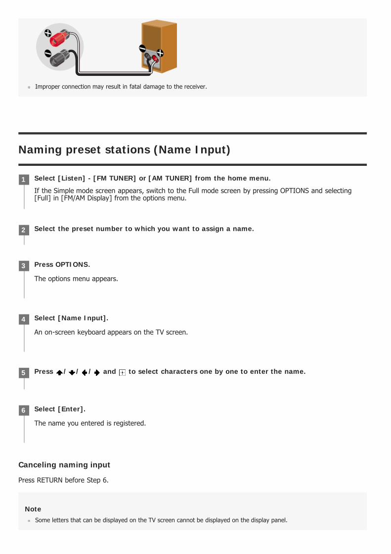
Improper connection may result in fatal damage to the receiver.
Naming preset stations (Name Input)
Canceling naming input
Press RETURN before Step 6.
NoteSome letters that can be displayed on the TV screen cannot be displayed on the display panel.
Select [Listen] - [FM TUNER] or [AM TUNER] from the home menu.
If the Simple mode screen appears, switch to the Full mode screen by pressing OPTIONS and selecting[Full] in [FM/AM Display] from the options menu.
1
Select the preset number to which you want to assign a name.2
Press OPTIONS.
The options menu appears.
3
Select [Name Input].
An on-screen keyboard appears on the TV screen.
4
Press / / / and to select characters one by one to enter the name.5
Select [Enter].
The name you entered is registered.
6
HintYou can also select [Name Input] from [Tuner Setup] in the [System Setup] menu instead of performing steps 1 to 4.
Menu list (on the display panel)
The following options are available in each menu.
1. Input Setup [1. INPUT SETUP]BD/DVD [1.1. BD/DVD]SAT/CATV [1.2. SAT/CATV]GAME [1.3. GAME]STB [1.4. STB]VIDEO [1.5. VIDEO]AUX [1.6. AUX]TV [1.7. TV]SA-CD/CD [1.8. SA-CD/CD]
2. Speaker Setup [2. SPEAKER SETUP]Auto Calibration [2.1. AUTO CALIBRATION]Automatic Phase Matching [2.2. AUTOMATIC PHASE MATCHING] (*1)AUTO, OFFCalibration type [2.3. CALIBRATION TYPE] (*1)FULL FLAT, ENGINEER, FRONT REF., OFFSpeaker pattern [2.4. SPEAKER PATTERN]7.1.2 (SBD) to 2.0 (112 patterns) (for STR-ZA3100ES/STR-ZA2100ES) 7.1 to 2.0 (40 patterns) (for STR-ZA1100ES)Surround back speaker assign [2.6. SB SPEAKER ASSIGN] (*2)ZONE2, BI-AMP, FRONT B, OFFSize [2.7. SIZE]XXX LARGE or XXX SMALL (*3)Distance [2.8. DISTANCE]XXX 1.00 m to XXX 10.00 m (XXX 3’3” to XXX 32’9”) (0.01 m (1 inch) interval) (*4)Level [2.9. LEVEL]XXX -10.0 dB to XXX +10.0 dB (0.5 dB interval) (*4)Test Tone [2.10. TEST TONE] (*5)OFF, AUTO XXX -10.0 dB to XXX +10.0 dB (1 dB interval), FIX XXX -10.0 dB to XXX +10.0 dB (1 dB interval)(*4)Crossover Frequency [2.11. CROSSOVER FREQUENCY] XXX 40 Hz to XXX 200 Hz (10 Hz interval) (*3) (*6)Equalizer [2.12. EQUALIZER]XXX TREBLE -10.0 dB to XXX TREBLE +10.0 dB (1 dB interval), XXX BASS -10.0 dB to XXX BASS +10.0 dB (1dB interval) (*3)Center Speaker Lift Up [2.13. CENTER SPEAKER LIFT UP]1 to 10, OFFSurround Speaker Position [2.14. SURROUND SPEAKER POSITION]FRONT, BACKSpeaker Relocation [2.15. SPEAKER RELOCATION]TYPE A, TYPE B, OFFCeiling Height [2.16. CEILING HEIGHT]2.00 m to 10.00 m (6’6” to 32’9”) (0.01 m (1 inch) interval)Distance Unit [2.17. DISTANCE UNIT]METER, FEET
3. Network Setup [3. NETWORK SETUP]Internet Setup [3.1. INTERNET SETUP]Information [3.2. INFORMATION]
Network Standby [3.3. NETWORK STANDBY]ON, OFFMusic Connect [3.4. MUSIC CONNECT]
4. Audio Setup [4. AUDIO SETUP]Digital Legato Linear [4.1. DIGITAL LEGATO LINEAR]AUTO1, AUTO2, OFFSound Optimizer [4.2. SOUND OPTIMIZER]NORMAL, LOW, OFFSound Field [4.3. SOUND FIELD]2CH STEREO, DIRECT, A.F.D., DOLBY SUR, NEURAL:X, MULTI STEREOIn-Ceiling Speaker Mode [4.4. IN-CEILING SPEAKER MODE]FRONT&CENTER, FRONT, OFFPure Direct [4.5. PURE DIRECT]ON, OFFSubwoofer Low Pass Filter [4.6. SUBWOOFER LOW PASS FILTER]ON, OFFSynchronizes audio with video output [4.7. A/V SYNC]HDMI AUTO, 0 ms to 300 ms (10 ms interval)Digital broadcast language selection [4.8. DUAL MONO]MAIN, SUB, MAIN/SUBDynamic Range Compressor [4.9. DYNAMIC RANGE COMPRESSOR]AUTO, ON, OFFNeural:X [4.10. NEURAL:X]ON, OFF
5. HDMI Setup [5. HDMI SETUP]4K Scaling [5.1. 4K SCALING]AUTO, OFFControl for HDMI [5.2. CONTROL FOR HDMI]ON, OFFStandby Linked to TV [5.3. STANDBY LINKED TO TV]ON, AUTOAudio Return Channel [5.4. AUDIO RETURN CHANNEL]STANDARD, OFFStandby Through [5.5. STANDBY THROUGH]AUTO, ON, OFFHDMI Audio Out [5.6. AUDIO OUT]AMP, TV+AMPHDMI Zone2 Audio Out [5.7. ZONE2 AUDIO OUT]AMP, ZONE2 TV+AMP, ZONE2 AMPHDMI Subwoofer Level [5.8. SUBWOOFER LEVEL]AUTO, +10 dB, 0 dBHDMI OUTB Mode [5.9. HDMI OUTB MODE]MAIN, ZONE2Priority [5.10. PRIORITY]MAIN&ZONE2, MAIN ONLYFast View [5.11. FAST VIEW]AUTO, OFFHDMI Signal Format [5.12. HDMI SIGNAL FORMAT]STANDARD, ENHANCED
6. Zone Setup [6. ZONE SETUP]Zone Controls [6.1.ZONE CONTROLS]
Zone2 Power [6.1.1 ZONE2 POWER]ON, OFFZone2 Input [6.1.2 ZONE2 INPUT]SOURCE, BD/DVD, SAT/CATV, GAME, STB, VIDEO, AUX, TV, SA-CD/CD, FM TUNER, AM TUNERZone2 Volume [6.1.3 ZONE2 VOLUME]OFF, -oodB to +23.0dB (*7) OFF, MIN to MAX (*8)Zone3 Power [6.1.4 ZONE3 POWER]ON, OFFZone3 Input [6.1.5 ZONE3 INPUT]SOURCE, VIDEO, AUX, TV, SA-CD/CD, FM TUNER, AM TUNERZone3 Volume [6.1.6 ZONE3 VOLUME]
OFF, -oodB to +23.0dB (*7) OFF, MIN to MAX (*8)
Main Preset Volume [6.2. MAIN PRESET VOLUME] OFF, -oodB to +23.0dB (*7) OFF, MIN to MAX (*8)Main Max Volume [6.3. MAIN MAX VOLUME] OFF, - 40.0dB to +23.0dB (*7) OFF, 13 to MAX (*8)Zone2 Preset Volume [6.4. ZONE2 PRESET VOLUME] OFF, -oodB to +23.0dB (*7) OFF, MIN to MAX (*8)Zone2 Max Volume [6.5. ZONE2 MAX VOLUME] OFF, - 40.0dB to +23.0dB (*7) OFF, 13 to MAX (*8)Zone2 Line Out [6.6. ZONE2 LINE OUT]VARIABLE, FIXEDZone3 Preset Volume [6.7. ZONE3 PRESET VOLUME] OFF, -oodB to +23.0dB (*7) OFF, MIN to MAX (*8)Zone3 Max Volume [6.8. ZONE3 MAX VOLUME] OFF, - 40.0dB to +23.0dB (*7) OFF, 13 to MAX (*8)Zone3 Line Out [6.9. ZONE3 LINE OUT]VARIABLE, FIXED
7. System Setup [7. SYSTEM SETUP]Language [7.1. LANGUAGE]ENGLISH, SPANISH, FRENCHAuto Display [7.2. AUTO DISPLAY]ON, OFFAuto standby mode [7.3. AUTO STANDBY]ON, OFFVolume Display [7.4. VOLUME DISPLAY]RELATIVE, ABSOLUTEDimmer [7.5. DIMMER]BRIGHT, DARK, OFFSleep timer [7.6. SLEEP]OFF - 0:30:00 - 1:00:00 - 1:30:00 - 2:00:00Software Version [7.7. SOFTWARE VERSION]x.xxx (*9)Network Update [7.8. NET UPDATE]USB Update [7.9. USB UPDATE]Tuner Setup [7.10. TUNER SETUP]
8. Install Setup [8. INSTALL SETUP]External Control [8.1. EXTERNAL CONTROL]ON, OFFTrigger 1 [8.2. TRIGGER 1] (*10)USE, ---Trigger 2 [8.3. TRIGGER 2] (*10)USE, ---Trigger 3 [8.4. TRIGGER 3] (*10)USE, ---Trigger [8.2. TRIGGER] (*11)USE, ---Test Picture for HDMI Out A [8.5. TEST OUT A] (*10)/[8.3. TEST OUT A] (*11) 4K/60Hz/4:4:4, 4K/24Hz/4:4:4, 1080p/60Hz, 480p/60Hz, OFFTest Picture for HDMI Out B [8.6. TEST OUT B] (*10)/[8.4. TEST OUT B] (*11) 4K/60Hz/4:4:4, 4K/24Hz/4:4:4, 1080p/60Hz, 480p/60Hz, OFFSave/Load [8.7. SAVE/LOAD] (*10)/[8.5. SAVE/LOAD] (*11)Settings Lock [8.8. SETTINGS LOCK] (*10)/[8.6. SETTINGS LOCK] (*11)
9. Easy Setup [9. EASY SETUP]Auto Calibration [9.1. AUTO CALIBRATION]Internet Setup [9.2. INTERNET SETUP]

Setting the FM station receiving mode (FM Mode)
You can set the FM station receiving mode to the stereo mode or monaural mode.
NoteYou can set FM mode in the options menu if the frequency indication is selected in step 3.
HintYou can also set FM mode with [Tuner Setup] in the [System Setup] menu.
You can select this setting only when you have performed Auto Calibration and saved the settings.*1You can only select this parameter if [SP PATTERN] is not set to a pattern with surround back speakers.*2XXX represents a speaker channel (FRONT, CENTER, SURROUND, HEIGHT1 (*12), HEIGHT2 (*12), HEIGHT (*13)).*3XXX represents a speaker channel (FRONT L, FRONT R, CENTER, SURROUND L, SURROUND R, SUR BACK L, SUR BACK R, SUR BACK,HEIGHT1 L (*12), HEIGHT1 R (*12), HEIGHT2 L (*12), HEIGHT2 R (*12), HEIGHT L (*13), HEIGHT R (*13), SUBWOOFER).
*4
Some parameters or settings may not be available depending on the speaker pattern setting.*5You can only select this parameter if the speaker is set to [SMALL].*6When [Setup] - [System Setup] - [Volume Display] is set to [Relative].*7When [Setup] - [System Setup] - [Volume Display] is set to [Absolute].*8x.xxx represents the version number.*9for STR-ZA3100ES*10for STR-ZA2100ES/STR-ZA1100ES*11for STR-ZA3100ES/STR-ZA2100ES*12for STR-ZA1100ES*13
Select [Listen] - [FM TUNER] from the home menu.
If the Simple mode screen appears, switch to the Full mode screen by pressing OPTIONS and selecting[Full] in [FM/AM Display] from the options menu.
1
Select a station on the FM band.2
Press OPTIONS.3
Select [FM Mode] from the options menu.4
Select the setting you want.
Stereo: The FM station is received in stereo.Monaural: The FM station is received in monaural.
5
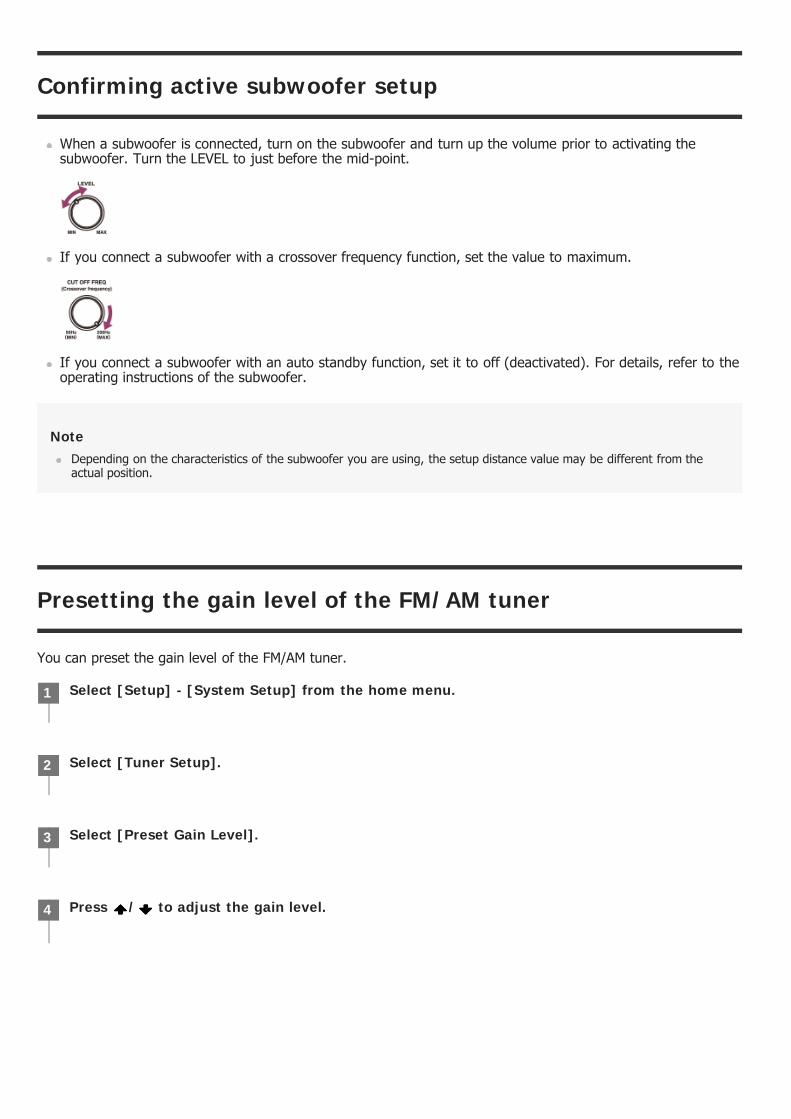
Confirming active subwoofer setup
When a subwoofer is connected, turn on the subwoofer and turn up the volume prior to activating thesubwoofer. Turn the LEVEL to just before the mid-point.
If you connect a subwoofer with a crossover frequency function, set the value to maximum.
If you connect a subwoofer with an auto standby function, set it to off (deactivated). For details, refer to theoperating instructions of the subwoofer.
NoteDepending on the characteristics of the subwoofer you are using, the setup distance value may be different from theactual position.
Presetting the gain level of the FM/AM tuner
You can preset the gain level of the FM/AM tuner.
Select [Setup] - [System Setup] from the home menu.1
Select [Tuner Setup].2
Select [Preset Gain Level].3
Press / to adjust the gain level.4


![MULTI CHANNEL AV RECEIVER STR-ZA3000ES/STR …Requisitos del sistema para una conexión LAN por cables [19] Cómo conectar el receptor a la red (para STR-ZA3000ES) [20] ... Como interconectar](https://static.fdocuments.us/doc/165x107/5e97f026356be20d9d6187c1/multi-channel-av-receiver-str-za3000esstr-requisitos-del-sistema-para-una-conexin.jpg)