ATM Commands - cisco.com · WR-1 Cisco IOS Wide-Area Networking Command Reference 78-11752-02 ATM...
44
WR-1 Cisco IOS Wide-Area Networking Command Reference 78-11752-02 ATM Commands This chapter describes the commands available for configuring ATM interfaces on the following platforms: • Cisco 2600 series routers • Cisco 3600 series routers • Cisco 4500 routers • Cisco 4700 routers • Cisco 7200 series routers • Cisco 7500 series routers This chapter also describes the commands available for configuring a serial interface for ATM access in other routers. Note Beginning in Cisco IOS Release 11.3, all commands supported on the Cisco 7500 series routers are also supported on the Cisco 7000 series routers equipped with RSP7000. For ATM configuration information and examples, refer to the chapter “Configuring ATM” in the Cisco IOS Wide-Area Networking Configuration Guide.
Transcript of ATM Commands - cisco.com · WR-1 Cisco IOS Wide-Area Networking Command Reference 78-11752-02 ATM...

WR-1Cisco IOS Wide-Area Networking Command Reference
78-11752-02
ATM Commands
This chapter describes the commands available for configuring ATM interfaces on the following platforms:
• Cisco 2600 series routers
• Cisco 3600 series routers
• Cisco 4500 routers
• Cisco 4700 routers
• Cisco 7200 series routers
• Cisco 7500 series routers
This chapter also describes the commands available for configuring a serial interface for ATM access in other routers.
Note Beginning in Cisco IOS Release 11.3, all commands supported on the Cisco 7500 series routers are also supported on the Cisco 7000 series routers equipped with RSP7000.
For ATM configuration information and examples, refer to the chapter “Configuring ATM” in the Cisco IOS Wide-Area Networking Configuration Guide.
ATM Commandsabr
WR-2Cisco IOS Wide-Area Networking Command Reference
78-11752-02
abrTo select available bit rate (ABR) quality of service (QoS) and configure the output peak cell rate and output minimum guaranteed cell rate for an ATM permanent virtual circuit (PVC) or virtual circuit (VC) class, use the abr command in the appropriate command mode. To remove the ABR parameters, use the no form of this command.
abr output-pcr output-mcr
no abr output-pcr output-mcr
Syntax Description
Defaults ABR QoS at the maximum line rate of the physical interface
Command Modes Interface-ATM-VC configuration (for an ATM PVC)
VC-class configuration (for a VC class)
PVC range configuration (for an ATM PVC range)
PVC-in-range configuration (for an individual PVC within a PVC range)
Command History
Usage Guidelines If the abr command is not explicitly configured on an ATM PVC, the VC inherits the following default configuration (listed in order of precedence):
• Configuration of any QoS command (abr, ubr, ubr+, or vbr-nrt) in a VC class assigned to the PVC itself.
• Configuration of any QoS command (abr, ubr, ubr+, or vbr-nrt) in a VC class assigned to the PVC’s ATM subinterface.
• Configuration of any QoS command (abr, ubr, ubr+, or vbr-nrt) in a VC class assigned to the PVC’s ATM main interface.
• Global default value: ABR QoS at the maximum line rate of the PVC.
ABR is a quality of service class defined by the ATM Forum for ATM networks. ABR is used for connections that do not require timing relationships between source and destination. ABR provides no guarantees in terms of cell loss or delay, providing only best-effort service. Traffic sources adjust their transmission rate in response to information they receive describing the status of the network and its capability to successfully deliver data.
output-pcr The output peak cell rate in kilobits per second.
output-mcr The output minimum guaranteed cell rate in kilobits per second.
Release Modification
11.1 This command was introduced.
12.1(5)T This command was modified to be available in PVC range and PVC-in-range configuration modes.

ATM Commandsabr
WR-3Cisco IOS Wide-Area Networking Command Reference
78-11752-02
In ABR transmission, the peak cell rate (PCR) specifies the maximum value of the allowed cell rate (ACR), and minimum cell rate (MCR) specifies the minimum value for the ACR. ACR varies between the MCR and the PCR and is dynamically controlled using congestion control mechanisms.
Examples The following example specifies the output-pcr argument to be 100,000 kbps and the output-mcr argument to be 3000 kbps for an ATM PVC:
pvc 1/32abr 100000 3000
Related Commands Command Description
ubr Configures UBR QoS and specifies the output peak cell rate for an ATM PVC, SVC, VC class, or VC bundle member.
ubr+ Configures UBR QoS and specifies the output peak cell rate and output minimum guaranteed cell rate for an ATM PVC, SVC, VC class or VC bundle member.
vbr-nrt Configures the VBR-NRT QoS and specifies output peak cell rate, output sustainable cell rate, and output maximum burst cell size for an ATM PVC, SVC, or VC class.

ATM Commandsatm aal aal3/4
WR-4Cisco IOS Wide-Area Networking Command Reference
78-11752-02
atm aal aal3/4To enable support for ATM adaptation layer 3/4 (AAL3/4) on an ATM interface, use the atm aal aal3/4 interface configuration command. To disable support for ATM adaptation layer 3/4 (AAL3/4) on an ATM interface, use the no form of this command.
atm aal aal3/4
no atm aal aal3/4
Syntax Description This command has no arguments or keywords.
Defaults Support for AAL3/4 is disabled.
Command Modes Interface configuration
Command History
Usage Guidelines This command is supported on Cisco 7500 series routers with AIP. This command is not supported on the ATM port adapter. Because Cisco 4500 and Cisco 4700 routers always support both AAL3/4 and AAL5, this command is not required on Cisco 4500 and Cisco 4700 routers.
Only one virtual circuit can exist on a subinterface that is being used for AAL3/4 processing, and that virtual circuit must be an AAL3/4 virtual circuit.
The AAL3/4 support feature requires static mapping of all protocols except IP.
Examples The following example enables AAL3/4 on ATM interface 2/0:
interface atm2/0ip address 172.21.177.178 255.255.255.0atm aal aal3/4
Related Commands
Release Modification
10.3 This command was introduced.
Command Description
atm mid-per-vc Limits the number of MID numbers allowed on each VC.
atm multicast Assigns an SMDS E.164 multicast address to the ATM subinterface that supports AAL3/4 and SMDS encapsulation.
atm smds-address Assigns a unicast E.164 address to the ATM subinterface that supports AAL3/4 and SMDS encapsulation.
pvc Creates or assigns a name to an ATM PVC, specifies the encapsulation type on an ATM PVC, or enters interface-ATM-VC configuration mode.

ATM Commandsatm abr rate-factor
WR-5Cisco IOS Wide-Area Networking Command Reference
78-11752-02
atm abr rate-factorTo configure the amount by which the cell transmission rate increases or decreases in response to flow control information from the network or destination for available bit rate (ABR) virtual circuits (VCs), use the atm abr rate-factor interface configuration command. To return to the default, use the no form of this command.
atm abr rate-factor [rate-increase-factor] [rate-decrease-factor]
no atm abr rate-factor [rate-increase-factor] [rate-decrease-factor]
Syntax Description
Defaults ABR rate increase and decrease factor is 16.
Command Modes Interface configuration
Command History
Usage Guidelines To configure an ABR VC, use the pvc command with the abr keyword.
To verify the ABR rate factor, use the show atm interface atm EXEC command.
Examples The following example sets the ABR rate factor to 32 for the next cell transferred on ATM interface 4/0:
interface atm 4/0atm abr rate-factor 32 32
Related Commands
rate-increase-factor (Optional) Factor by which to increase the data rate. The rate increase factor is specified in powers of 2 from 1 to 32768.
rate-decrease-factor (Optional) Factor by which to decrease the data rate. The rate decrease factor is specified in powers of 2 from 1 to 32768.
Release Modification
11.1 This command was introduced.
Command Description
pvc Configures the PVC interface.
show atm interface atm Displays ATM-specific information about an ATM interface.
ATM Commandsatm address-registration
WR-6Cisco IOS Wide-Area Networking Command Reference
78-11752-02
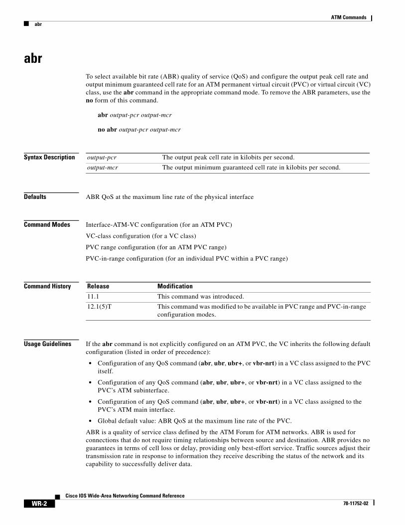
atm address-registrationTo enable the router to engage in address registration and callback functions with the Interim Local Management Interface (ILMI), use the atm address-registration interface configuration command. To disable ILMI address registration functions, use the no form of this command.
atm address-registration
no atm address-registration
Syntax Description This command has no arguments or keywords.
Defaults Enabled
Command Modes Interface configuration
Command History
Usage Guidelines This command enables a router to register its address with the ILMI for callback when specific events occur, such as incoming Simple Network Management Protocol (SNMP) traps or incoming new network prefixes.
Examples The following example enables ATM interface I/O to register its address:
interface atm 1/0atm address-registration
Related Commands
Release Modification
11.0 This command was introduced.
Command Description
atm ilmi-keepalive Enables ILMI keepalives.

ATM Commandsatm arp-server
WR-7Cisco IOS Wide-Area Networking Command Reference
78-11752-02
atm arp-serverTo identify an ATM Address Resolution Protocol (ARP) server for the IP network or set time-to-live (TTL) values for entries in the ATM ARP table, use the atm arp-server interface configuration command. To remove the definition of an ATM ARP server, use the no form of this command.
atm arp-server [self [time-out minutes] | [nsap nsap-address]]
no atm arp-server [self [time-out minutes] | [nsap nsap-address]]
Syntax Description
Defaults The default timeout value is 20 minutes.
The ARP server process is disabled.
Command Modes Interface configuration
Command History
Usage Guidelines If an NSAP address is specified, the ARP client on this interface uses the specified host as an ARP server. You can specify multiple ATM ARP servers by repeating the command. If self is specified, this interface acts as the ARP server for the logical IP network.
The ATM ARP server takes one of the following actions if a destination listed in the server’s ARP table expires:
• If a virtual circuit still exists to that destination, the server sends an Inverse ARP request. If no response arrives, the entry times out.
• If a virtual circuit does not exist to the destination, the entry times out immediately.
This implementation follows RFC 1577, Classical IP over ATM.
To configure redundant ARP servers, you must first enable redundant ARP server support by entering the atm classic-ip-extensions command with the BFI keyword.
self (Optional) Specifies the current router as the ATM ARP server.
time-out minutes (Optional) Number of minutes for which a destination entry listed in the ATM ARP server’s ARP table will be kept before the server takes any action to verify or time out the entry.
nsap nsap-address (Optional) Network service access point (NSAP) address of an ATM ARP server.
Release Modification
11.1 This command was introduced.
ATM Commandsatm arp-server
WR-8Cisco IOS Wide-Area Networking Command Reference
78-11752-02
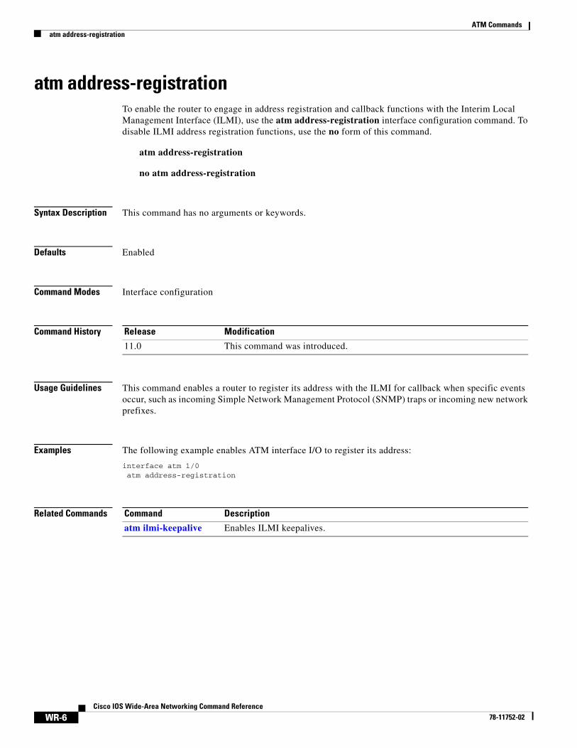
Examples The following example configures ATM on an interface and configures the interface to function as the ATM ARP server for the IP subnetwork:
interface atm 0/0ip address 10.0.0.1.255.0.0.0
atm nsap-address ac.1533.66.020000.0000.0000.0000.0000.0000.0000.00atm rate-queue 1 100atm maxvc 1024atm pvc 1 0 5 qsaalatm arp-server self
Related Commands Command Description
atm classic-ip-extensions Enables support for redundant ATM ARP servers on a single LIS.

ATM Commandsatm classic-ip-extensions
WR-9Cisco IOS Wide-Area Networking Command Reference
78-11752-02
atm classic-ip-extensionsTo enable support for redundant ATM Address Resolution Protocol (ARP) servers on a single logical IP subnetwork (LIS), use the atm classic-ip-extensions command in interface configuration mode. To remove support for redundant ATM ARP servers, use the no form of this command.
atm classic-ip-extensions {BFI | none}
no atm classic-ip-extensions
Syntax Description
Defaults Redundant ATM ARP server support is not enabled.
Command Modes Interface configuration
Command History
Usage Guidelines Cisco’s implementation of the ATM ARP server supports redundant ATM ARP servers on a single logical IP subnetwork (LIS). In order for redundant ATM ARP server support to work, all of the devices on the LIS must be Cisco devices and must have the atm classic-ip-extensions BFI command configured.
The none keyword enables behavior that complies with RFC 1577, Classical IP over ATM. RFC 1577 does not support redundant ARP servers.
Examples The following example shows how to configure redundant ARP servers on an ATM interface:
Router(config)# interface atm 1/0Router(config-if)# atm classic-ip-atm BFIRouter(config-if)# atm arp-server nsap 47.000580FFE1000000F21A3167.666666666666.00Router(config-if)# atm arp-server nsap 47.000580FFE1000000F21A3167.555555555555.00
Related Commands
BFI Enables simple redundant ARP server support. BFI as an acronym is undefined.
none Enables standard RFC 1577 behavior (no redundant ARP server support).
Release Modification
11.2 This command was introduced.
Command Description
atm arp-server Identifies an ATM Address Resolution Protocol (ARP) server for the IP network or sets TTL values for entries in the ATM ARP table.
ATM Commandsatm clock internal
WR-10Cisco IOS Wide-Area Networking Command Reference
78-11752-02
atm clock internalTo cause the ATM interface to generate the transmit clock internally, use the atm clock internal interface configuration command. To restore the default value, use the no form of this command.
atm clock internal
no atm clock internal
Syntax Description This command has no arguments or keywords.
Defaults The ATM interface uses the transmit clock signal from the remote connection (the line). The switch provides the clocking.
Command Modes Interface configuration
Command History
Usage Guidelines This command is meaningless on a 4B/5B physical layer interface module (PLIM).
For SONET interfaces, use the atm clock internal command to configure an ATM port adapter to supply its internal clock to the line.
Examples The following example causes the ATM interface to generate the transmit clock internally:
interface atm 4/0atm clock internal
Release Modification
10.0 This command was introduced.

ATM Commandsatm compression
WR-11Cisco IOS Wide-Area Networking Command Reference
78-11752-02
atm compressionTo specify the software compression mode on an interface, use the atm compression command in interface configuration mode. To remove the compression mode setting, use the no form of this command.
atm compression {per-packet | per-interface | per-vc}
no atm compression {per-packet | per-interface | per-vc}
Syntax Description
Defaults per-packet
Command Modes Interface configuration
Command History
Usage Guidelines This command applies to ATM configuration on the Cisco MC3810 multiservice concentrator.
Examples The following example configures per-packet ATM compression:
interface atm0atm compression per-packet
per-packet Specifies packet-by-packet compression mode (no history). This is the default.
per-interface Specifies one context per interface (with history).
per-vc Specifies one context for every virtual circuit (with history).
Release Modification
11.3(1)MA This command was introduced on the Cisco MC3810 multiservice concentrator.

ATM Commandsatm ds3-scramble
WR-12Cisco IOS Wide-Area Networking Command Reference
78-11752-02
atm ds3-scrambleTo enable scrambling of the ATM cell payload for the DS3 physical layer interface module (PLIM) on an ATM interface, use the atm ds3-scramble interface configuration command. To disable scrambling of the ATM cell payload for the DS3 PLIM, use the no form of this command.
atm ds3-scramble
no atm ds3-scramble
Syntax Description This command has no arguments or keywords.
Defaults Disabled
Command Modes Interface configuration
Command History
Usage Guidelines DS3 scrambling is used to assist clock recovery on the receiving end.
Examples The following example disables DS3 scrambling on the interface:
interface atm 4/0no atm ds3-scramble
Release Modification
11.0 This command was introduced.
11.1 Command syntax was changed from ds3 scramble to atm ds3-scramble.

ATM Commandsatm e164 auto-conversion
WR-13Cisco IOS Wide-Area Networking Command Reference
78-11752-02
atm e164 auto-conversionTo enable ATM E164 autoconversion, use the atm e164 auto-conversion interface configuration command. To disable autoconversion, use the no form of this command.
atm e164 auto-conversion
no atm e164 auto-conversion
Syntax Description This command has no arguments or keywords.
Defaults Disabled
Command Modes Interface configuration
Command History
Usage Guidelines You must enable the ATM interface before using the atm e164 auto-conversion command.
When an interface is configured for E.164 auto conversion, ATM E.164 format addresses are converted to the corresponding native E.164 address for outgoing calls. For incoming calls, native E.164 addresses are converted to the corresponding ATM E.164 format.
Examples The following example enables E.164 auto conversion on ATM interface 0/0/1:
interface atm 0/0/1atm e164 auto-conversion
Release Modification
11.3 This command was introduced.
ATM Commandsatm e3-scramble
WR-14Cisco IOS Wide-Area Networking Command Reference
78-11752-02
atm e3-scrambleTo enable scrambling of the ATM cell payload for the E3 physical layer interface module (PLIM) on an ATM interface, use the atm e3-scramble interface configuration command. To disable scrambling of the ATM cell payload for the E3 PLIM, use the no form of this command.
atm e3-scramble
no atm e3-scramble
Syntax Description This command has no arguments or keywords.
Defaults E3 scrambling is enabled.
Command Modes Interface configuration
Command History
Usage Guidelines E3 scrambling is used to assist clock recovery on the receiving end.
Examples The following example disables E3 scrambling on the interface:
interface atm 2/0no atm e3-scramble
Release Modification
11.1 This command was introduced.

ATM Commandsatm esi-address
WR-15Cisco IOS Wide-Area Networking Command Reference
78-11752-02
atm esi-addressTo enter the end station ID (ESI) and selector byte fields of the ATM network service access point (NSAP) address, use the atm esi-address interface configuration command. The NSAP address prefix is filled in via Integrated Local Management Interface (ILMI) from the ATM switch. To delete the end station address, use the no form of this command.
atm esi-address esi.selector
no atm esi-address esi.selector
Syntax Description
Defaults No ESI is defined.
Command Modes Interface configuration
Command History
Usage Guidelines The atm esi-address command allows you to configure the ATM address by entering the ESI (12 hexadecimal characters) and the selector byte (2 hexadecimal characters). The ATM prefix (26 hexadecimal characters) will be provided by the ATM switch. To get the prefix from the ATM switch, the ILMI permanent virtual circuit (PVC) must be configured on the router and the ATM switch must be able to supply a prefix via ILMI. A period must be used to separate the esi from the selector arguments.
Note When ILMI is configured, use the atm esi-address command instead of the atm nsap-address command. The atm esi-address and atm nsap-address commands are mutually exclusive. Configuring the router with the atm esi-address command negates the atm nsap-address setting, and vice versa.
The ILMI PVC must be configured in order to get an NSAP address prefix from the switch.
Examples The following example sets up the ILMI PVC and assigns the ESI and selector field values on the ATM interface 4/0:
interface atm 4/0atm pvc 2 0 16 ilmiatm esi-address 345678901234.12
esi End station ID field value in hexadecimal; 6 bytes long.
.selector Selector field value in hexadecimal; 1 byte long.
Release Modification
11.1 This command was introduced.

ATM Commandsatm esi-address
WR-16Cisco IOS Wide-Area Networking Command Reference
78-11752-02
Related Commands Command Description
atm nsap-address Sets the NSAP address for an ATM interface using SVC mode.
ilmi manage Enables ILMI management on an ATM PVC.
pvc Configures the PVC interface.

ATM Commandsatm exception-queue
WR-17Cisco IOS Wide-Area Networking Command Reference
78-11752-02
atm exception-queueTo set the exception queue length, use the atm exception-queue interface configuration command. To restore the default value, use the no form of this command.
atm exception-queue number
no atm exception-queue
Syntax Description
Defaults 32 entries
Command Modes Interface configuration
Command History
Usage Guidelines This command is supported on ATM interface processor (AIP) for Cisco 7500 series routers. This command is not supported on the ATM port adapter for Cisco 7200 and 7500 series routers, nor is it supported on Cisco 4500 and Cisco 4700 routers.
The exception queue is used for reporting ATM events, such as cycle redundancy check (CRC) errors.
Examples The following example sets the exception queue to 50 entries:
atm exception-queue 50
number Number of entries, in the range from 8 to 256.
Release Modification
10.0 This command was introduced.

ATM Commandsatm framing (DS3)
WR-18Cisco IOS Wide-Area Networking Command Reference
78-11752-02
atm framing (DS3)To specify DS3 line framing on an ATM interface, use the atm framing interface configuration command. To return to the default C-bit with Physical Layer Convergence Protocol (PLCP) framing, use the no form of this command.
atm framing [cbitadm | cbitplcp | m23adm | m23plcp]
no atm framing [cbitadm | cbitplcp | m23adm | m23plcp]
Syntax Description
Defaults cbitplcp
Command Modes Interface configuration
Command History
Usage Guidelines This command is available on Cisco 4500 and 4700 routers with DS3 access speeds, Cisco 7200 series routers, and Cisco 7500 series routers.
Framing on the interface must match that on the switch for this ATM link.
Examples The following example specifies M23 ADM framing on a router that has been set up with DS3 access to an ATM network:
interface atm 4/0atm framing m32adm
cbitadm (Optional) Specifies C-bit with ATM direct mapping (ADM).
cbitplcp (Optional) Specifies C-bit with PLCP framing.
m23adm (Optional) Specifies M23 ATM direct mapping.
m23plcp (Optional) Specifies M23 with PLCP framing.
Release Modification
11.0 This command was introduced.
11.1 This command was modified to include the Cisco 7200 series routers with the ATM-CES port adapter.

ATM Commandsatm framing (E3)
WR-19Cisco IOS Wide-Area Networking Command Reference
78-11752-02
atm framing (E3)To specify E3 line framing, use the atm framing interface configuration command. To return to the default G.751 Physical Layer Convergence Protocol (PLCP) framing, use the no form of this command.
atm framing [g751adm | g832adm | g751plcp]
no atm framing [g751adm | g832adm | g751plcp]
Syntax Description
Defaults g751plcp
Command Modes Interface configuration
Command History
Usage Guidelines The default framing is described in the ITU-T Recommendation G.751.
Framing on the interface must match that on the switch for this ATM link.
Examples The following example specifies G.832 ADM framing on a router that has been set up with E3 access to an ATM network:
interface atm 4/0atm framing g832adm
g751adm (Optional) Specifies G.751 ATM Direct Mapping (ADM).
g832adm (Optional) Specifies G.832 ATM Direct Mapping.
g751plcp (Optional) Specifies G.751 PLCP encapsulation.
Release Modification
11.0 This command was introduced.
11.1 The g751plcp keyword was added, together with information on the Cisco 7200 series router with the ATM-CES port adapter.

ATM Commandsatm ilmi-keepalive
WR-20Cisco IOS Wide-Area Networking Command Reference
78-11752-02
atm ilmi-keepaliveTo enable Interim Local Management Interface (ILMI) keepalives, use the atm ilmi-keepalive interface configuration command. To disable ILMI keepalives, use the no form of this command.
atm ilmi-keepalive [seconds]
no atm ilmi-keepalive [seconds]
Syntax Description
Defaults 3 seconds
Command Modes Interface configuration
Command History
Examples The following example enables ILMI keepalives for the ATM interface 1/0:
interface atm 1/0atm address-registrationatm ilmi-keepalive
Related Commands
seconds (Optional) Number of seconds between keepalives. Values less than 3 seconds are rounded up to 3 seconds, and there is no upper limit.
Release Modification
11.0 This command was introduced.
Command Description
atm address-registration Enables the router to engage in address registration and callback functions with the ILMI.

ATM Commandsatm ilmi-pvc-discovery
WR-21Cisco IOS Wide-Area Networking Command Reference
78-11752-02
atm ilmi-pvc-discoveryTo enable ATM permanent virtual circuit (PVC) discovery, use the atm ilmi-pvc-discovery interface configuration command. To disable PVC Discovery, use the no form of this command.
atm ilmi-pvc-discovery [subinterface]
no atm ilmi-pvc-discovery [subinterface]
Syntax Description
Defaults Disabled
Command Modes Interface configuration
Command History
Examples The following example enables PVC Discovery on the ATM main interface 2/0. The subinterface keyword is used so that all discovered PVCs with a VPI value of 1 will be assigned to the subinterface 2/0.1:
interface atm 2/0pvc RouterA 0/16 ilmiexitatm ilmi-pvc-discovery subinterfaceexit
interface atm 2/0.1 multipointip address 172.21.51.5 255.255.255.0
subinterface (Optional) Causes discovered PVCs to be assigned to the ATM subinterface whose number matches the discovered PVC’s VPI number.
Release Modification
11.3 This command was introduced.

ATM Commandsatm lbo
WR-22Cisco IOS Wide-Area Networking Command Reference
78-11752-02
atm lboTo specify the cable length (line build-out) for the ATM interface, use the atm lbo interface configuration command. To return to the default, use the no form of this command.
atm lbo {long | short}
no atm lbo
Syntax Description
Defaults short
Command Modes Interface configuration
Command History
Examples The following example specifies that the ATM interface use a cable less than 50 feet:
interface atm 4/0atm lbo short
Related Commands
long Specifies a cable length greater than 50 feet.
short Specifies a cable length less than 50 feet.
Release Modification
11.1 This command was introduced.
Command Description
ces dsx1 lbo Configures cable length for the CBR interface.

ATM Commandsatm max-channels
WR-23Cisco IOS Wide-Area Networking Command Reference
78-11752-02
atm max-channelsTo configure the number of transmit channels for the interface, use the atm max-channels interface configuration command. To return to the default, use the no form of this command.
atm max-channels number
no atm max-channels
Syntax Description
Defaults 64 channels
Command Modes Interface configuration
Command History
Usage Guidelines The atm max-channels command replaces the atm tx-channels command.
Transmit Descriptors
The atm max-channels command can be used to divide the available number (fixed) of transmit descriptors across the configured number of transmit channels. Typically, you think of a one-to-one association between a transmit channel and a VC; however, the ATM-CES port adapter supports other types of VCs than data VCs (for example CES VCs). Also, the ATM-CES port adapter can multiplex one or more VCs over a single virtual path (VP) that is shaped, and the VP only requires a single transmit channel. Therefore, the term transmit channel is used rather than virtual circuit.
Maximum Burst
The maximum burst of packets that are allowed per VC is limited by the number of transmit descriptors allocated per VC. Because the total number of transmit descriptors available is limited by the available SRAM space, configuration of the number of transmit channels for the interface determines the number of transmit descriptors for each transmit channel. Hence the burst size for each transmit channel is determined by the atm max-channels command. For example, for 64 (the default) transmit channels for the interface, 255 transmit descriptors are associated per channel, and for 512 transmit channels for the interface, 31 transmit descriptors are associated per channel.
To display information about the transmit descriptors, use the show atm interface atm command.
Examples The following example sets the number of transmit descriptors for the interface to 120.
interface atm 2/0atm max-channels 120
number Maximum number of transmit channels for the interface. The range is 64 to 2048 channels. The default is 64 channels.
Release Modification
11.1 This command was introduced.

ATM Commandsatm max-channels
WR-24Cisco IOS Wide-Area Networking Command Reference
78-11752-02
Related Commands Command Description
show atm interface atm Displays ATM-specific information about an ATM interface.

ATM Commandsatm maxvc
WR-25Cisco IOS Wide-Area Networking Command Reference
78-11752-02
atm maxvcTo set the ceiling value of the virtual circuit descriptor (VCD) on the ATM interface, use the atm maxvc interface configuration command. To restore the default value, use the no form of this command.
atm maxvc number
no atm maxvc
Syntax Description
Defaults 2048 virtual circuits
Command Modes Interface configuration
Command History
Usage Guidelines This command is supported on Cisco 7500 series routers; it is not supported on the Cisco 4500 and Cisco 4700 routers, which have a fixed maximum of 1024 VCs.
This command sets the maximum value supported for the vcd argument in the atm pvc command. It also determines the maximum number of virtual circuits on which the AIP allows segmentation and reassembly (SAR) to occur. However, if you set a maxvc limit and then enter the atm pvc command with a larger value for the vcd argument, the software does not generate an error message.
This command does not affect the virtual path identifier (VPI)-virtual channel identifier (VCI) pair of each virtual circuit.
Examples The following example sets a ceiling VCD value of 1024 and restricts the AIP to supporting no more than 1024 virtual circuits:
atm maxvc 1024
Related Commands
number Maximum number of supported virtual circuits. Valid values are 256, 512, 1024, or 2048.
Release Modification
10.0 This command was introduced.
Command Description
pvc Creates or assigns a name to an ATM PVC, specifies the encapsulation type on an ATM PVC, or enters interface-ATM-VC configuration mode.
ATM Commandsatm mid-per-vc
WR-26Cisco IOS Wide-Area Networking Command Reference
78-11752-02
atm mid-per-vcTo limit the number of message identifier (MID) numbers allowed on each virtual circuit, use the atm mid-per-vc interface configuration command.
atm mid-per-vc maximum
Syntax Description
Defaults 16 MIDs per virtual circuit.
Command Modes Interface configuration
Command History
Usage Guidelines This command is supported on Cisco 7200 and 7500 series routers.
MID numbers are used by receiving devices to reassemble cells from multiple sources into packets.
This command limits the number of discrete messages allowed on the PVC at the same time. It does not limit the number of cells associated with each message.
The maximum set by the atm mid-per-vc command overrides the range between the midhigh and midlow values set by the atm pvc command. If you set a maximum of 16 but a midlow of 0 and a midhigh of 255, only 16 MIDs (not 256) are allowed on the virtual circuit.
Examples The following example allows 64 MIDs per ATM virtual circuit:
atm mid-per-vc 64
Related Commands
maximum Number of MIDs allowed per virtual circuit on this interface. The values allowed are 16, 32, 64, 128, 256, 512, and 1024.
Release Modification
10.3 This command was introduced.
Command Description
pvc Configures the PVC interface.

ATM Commandsatm multicast
WR-27Cisco IOS Wide-Area Networking Command Reference
78-11752-02
atm multicastTo assign a Switched Multimegabit Data Service (SMDS) E.164 multicast address to the ATM subinterface that supports ATM adaptation layer 3/4 (AAL3/4) and SMDS encapsulation, use the atm multicast interface configuration command.
atm multicast address
Syntax Description
Defaults No multicast E.164 address is defined.
Command Modes Interface configuration
Command History
Usage Guidelines This command is supported on Cisco 7500 series, Cisco 4500, and Cisco 4700 routers. This command is not supported on the ATM port adapter.
Each AAL3/4 subinterface is allowed only one multicast E.164 address. This multicast address is used for all protocol broadcast operations.
Examples The following example assigns a multicast E.164 address to the ATM subinterface that is being configured:
atm multicast e180.0999.000
Related Commands
address Multicast E.164 address assigned to the subinterface.
Release Modification
10.3 This command was introduced.
Command Description
abr Selects ABR QoS and configures output peak cell rate and output minimum guaranteed cell rate for an ATM PVC or VC class.
atm smds-address Assigns a unicast E.164 address to the ATM subinterface that supports AAL3/4 and SMDS encapsulation.
pvc Configures the PVC interface.

ATM Commandsatm multipoint-interval
WR-28Cisco IOS Wide-Area Networking Command Reference
78-11752-02
atm multipoint-intervalTo specify how often new destinations can be added to multipoint calls to an ATM switch in the network, use the atm multipoint-interval interface configuration command. To return to the default interval, use the no form of this command.
atm multipoint-interval interval
no atm multipoint-interval interval
Syntax Description
Defaults 30 seconds
Command Modes Interface configuration
Command History
Usage Guidelines This command applies to switched virtual circuits (SVCs) only, not to permanent virtual circuits (PVCs).
This command has no effect unless ATM multipoint signalling is enabled on the interface.
Examples The following example enables point-to-multipoint signalling on the ATM interface 2/0. It also specifies that new destinations can be added to multipoint calls every 60 seconds:
interface atm 2/0atm multipoint-signallingatm multipoint-interval 60
Related Commands
interval Interval length in seconds, in the range from 0 to 4294967.
Release Modification
11.0 This command was introduced.
Command Description
atm multipoint-signalling Enables point-to-multipoint signalling to the ATM switch.

ATM Commandsatm multipoint-signalling
WR-29Cisco IOS Wide-Area Networking Command Reference
78-11752-02
atm multipoint-signallingTo enable point-to-multipoint signalling to the ATM switch, use the atm multipoint-signalling interface configuration command. To disable point-to-multipoint signalling to the ATM switch, use the no form of this command.
atm multipoint-signalling
no atm multipoint-signalling
Syntax Description This command has no arguments or keywords.
Defaults Disabled
Command Modes Interface configuration
Command History
Usage Guidelines If multipoint signalling is enabled, the router uses existing static map entries that have the broadcast keyword set to establish multipoint calls. One call is established for each logical subnet of each protocol.
All destinations are added to the call. One multicast packet is sent to the ATM switch for each multipoint call. The ATM switch replicates the packet to all destinations.
The atm multipoint-interval command determines how often new destinations can be added to a multipoint call.
Note Prior to Release 11.1, when this command was used on the main interface, it also affected all subinterfaces. For Release 11.1 and later, explicit configuration on each subinterface is required to obtain the same functionality.
Examples The following example enables point-to-multipoint signalling on the ATM interface 2/0:
interface atm 2/0atm multipoint-signalling
Related Commands
Release Modification
11.0 This command was introduced.
11.1 Functionality was changed to allow this command on all subinterfaces, not just the main interface.
Command Description
atm multipoint-interval Specifies how often new destinations can be added to multipoint calls to an ATM switch in the network.

ATM Commandsatm nsap-address
WR-30Cisco IOS Wide-Area Networking Command Reference
78-11752-02
atm nsap-addressTo set the network service access point (NSAP) address for an ATM interface using switched virtual circuit (SVC) mode, use the atm nsap-address interface configuration command. To remove any configured address for the interface, use the no form of this command.
atm nsap-address nsap-address
no atm nsap-address
Syntax Description
Defaults No NSAP address is defined for this interface.
Command Modes Interface configuration
Command History
Usage Guidelines When configuring an SVC, you must use the atm nsap-address command to define the source NSAP address. It identifies a particular port on the ATM network and must be unique across the network.
Note When the Integrated Local Management Interface (ILMI) is configured, use the atm esi-address command instead of the atm nsap-address command. The atm esi-address and atm nsap-address commands are mutually exclusive. Configuring the router with the atm esi-address command negates the atm nsap-address setting, and vice versa.
Configuring a new address on the interface overwrites the previous address. The router considers the address as a string of bytes and will not prefix or suffix the address with any other strings or digits. The complete NSAP address must be specified, because this value is used in the Calling Party Address Information Element in the SETUP message to establish a virtual circuit.
ATM NSAP addresses have a fixed length of 40 hexadecimal digits. You must configure the complete address in the following dotted format:
xx.xxxx.xx.xxxxxx.xxxx.xxxx.xxxx.xxxx.xxxx.xxxx.xx
Note All ATM NSAP addresses should be entered in the dotted hexadecimal format shown above, which conforms to the User-Network Interface (UNI) specification.The dotted method provides some validation that the address is a legal value. If you know your address format is correct, the dots may be omitted.
nsap-address The 40-digit hexadecimal NSAP address of this interface (the source address).
Release Modification
10.0 This command was introduced.

ATM Commandsatm nsap-address
WR-31Cisco IOS Wide-Area Networking Command Reference
78-11752-02
Examples In the following example, the source NSAP address for the interface is AB.CDEF.01.234567.890A.BCDE.F012.3456.7890.1234.12:
atm nsap-address AB.CDEF.01.234567.890A.BCDE.F012.3456.7890.1234.12

ATM Commandsatm oam flush
WR-32Cisco IOS Wide-Area Networking Command Reference
78-11752-02
atm oam flushTo drop all current and future Operation, Administration, and Maintenance (OAM) cells received on an ATM interface, use the atm oam flush interface configuration command. To receive OAM cells on an ATM interface, use the no form of this command.
atm oam flush
no atm oam flush
Syntax Description This command has no arguments or keywords.
Defaults Dropping of OAM cells is disabled.
Command Modes Interface configuration
Command History
Examples The following example drops all current and future OAM cells received on the ATM main interface with slot 0 and port 0:
interface atm 0/0atm oam flush
Release Modification
11.3 This command was introduced.
ATM Commandsatm oversubscribe
WR-33Cisco IOS Wide-Area Networking Command Reference
78-11752-02
atm oversubscribeTo manage bandwidth for service categories other than constant bit rate (CBR), use the atm overscribe global configuration command on a per-ATM-interface basis. To disable bandwidth management, use the no form of the command.
atm oversubscribe
no atm oversubscribe
Syntax Description This command has no arguments or keywords.
Defaults The default is to allow as much bandwidth as possible with no upper limits. The no form of the atm overscribe command enables bandwidth management on any ATM interface you specify.
Command Modes Global configuration
Command History
Usage Guidelines When you type the enabling command (the no version), a check determines if the ATM link is already oversubscribed. If so, the command is rejected. Otherwise, the total bandwidth available on the link is recorded and all future connection setup requests are monitored to ensure that the link is not oversubscribed.
The bandwidth allocated for each service category is displayed in the output of the show atm interface atm command.
The ATM bandwidth manager keeps track of bandwidth used by VCs on a per-interface basis. Because many services require guaranteed bandwidth (for variable bit rate-real time (VBR-RT), available bit rate (ABR), CBR, for instance), bandwidth management is required. The purpose of the bandwidth manager is to reserve resources for connections that require guaranteed services. Bandwidth management for CBR is turned on automatically for all interfaces supporting CBR. Bandwidth management for other service categories must be turned on by the user. All service categories outside CBR is monitored only if specifically requested.
Note Because unspecified bit rate (UBR) does not provide any guarantees, bandwidth specified for a UBR connection is not used in any calculations.
In all cases, bandwidth check for a PVC is done when the PVC is configured. Bandwidth check for a SVC is done when a signalling call is placed or received.
When you specify the atm pvp command, the system checks if the specified bandwidth is available on the interface. If the bandwidth available is greater than or equal to the peak rate specified for the Permanent Virtual Path (PVP), the command is accepted, otherwise the command is rejected.
Release Modification
12.0(3)T This command was introduced.

ATM Commandsatm oversubscribe
WR-34Cisco IOS Wide-Area Networking Command Reference
78-11752-02
Within the VC mode the steps taken to check for bandwidth available are to ascertain if the bandwidth is already used by the VC to fulfill the request. If the VC being configured is a PVC and belongs to a PVP, the bandwidth available on the PVP is used for the check; otherwise the bandwidth available on the interface is used for the check.
When configuring services within a VC class, the steps taken are to check if the new bandwidth requirement can be fulfilled for all VCs using the class (on a per-interface basis), by comparing with the bandwidth available on the corresponding interface.
Bandwidth checking for an SVC occurs before a SETUP message is sent for an outbound call. If the bandwidth check fails, the SETUP message is not sent. If the bandwidth check passes, the traffic class from which the service category is inherited, is updated with the requirements for the new SVC.
When an SVC setup is requested for remotely initiated calls, a bandwidth check occurs as soon as the SETUP message is received. This bandwidth check has two components:
• Match the bandwidth requested by the remote end with the bandwidth configured locally.
• Check if bandwidth configured locally can be satisfied currentl.
If the bandwidth check fails, a RELEASE message is sent out and the call is rejected. If the bandwidth check passes, resources are reserved for the VC and the call is accepted.
Examples The following example displays the available bandwidth after you enter VC mode. Notice that the bandwidth is specified in kbps.
Router# show atm interface atm 2/0Interface ATM2/0:AAL enabled: AAL5, Maximum VCs:1024, Current VCCs:5
Maximum Transmit Channels:64Max. Datagram Size:4496PLIM Type:SONET - 155Mbps, TX clocking:LINECell-payload scrambling:OFFsts-stream scrambling:ON877 input, 120843834 output, 0 IN fast, 20 OUT fastABR parameters, rif:16 rdf:16, 0 out dropBandwidth distribution :CBR :16000 Avail bw = 139000 Config. is ACTIVE
Notice that the bandwidth is specified as (139000) kbps.

ATM Commandsatm pvp
WR-35Cisco IOS Wide-Area Networking Command Reference
78-11752-02
atm pvpTo create a permanent virtual path (PVP) used to multiplex (or bundle) one or more virtual circuits (VCs), use the atm pvp interface configuration command. To remove a PVP, use the no form of this command.
atm pvp vpi [peak-rate]
no atm pvp vpi
Syntax Description
Defaults PVP is not configured.
The default peak-rate is the line rate.
Command Modes Interface configuration
Command History
Usage Guidelines This command is commonly used to create a PVP that is used multiplex circuit emulation service (CES) and data VCs.
The ATM-CES port adapter supports multiplexing of one or more VCs over a virtual path that is shaped at a constant bandwidth. For example, you can buy a virtual path service from an ATM service provider and multiplex both the CES and data traffic over the virtual path.
All subsequently created VCs with a vpi argument matching the vpi specified with the atm pvp command are multiplexed onto this PVP. This PVP connection is an ATM connection where switching is performed on the VPI field of the cell only. A PVP is created and left up indefinitely. All VCs that are multiplexed over a PVP share and are controlled by the traffic parameters associated with the PVP.
Changing the peak-rate argument causes the ATM-CES port adapter to go down and then back up.
When you create a PVP, two VC are created (VCI 3 and 4) by default. These VCs are created for VP end-to-end loopback and segment loopback OAM support.
To verify the configuration of a PVP, use the show atm vp EXEC command.
vpi ATM network virtual path identifier (VPI) of the VC to multiplex on the permanent virtual path. The range is 0 to 255. The VPI is an 8-bit field in the header of the ATM cell. The VPI value is unique only on a single link, not throughout the ATM network because it has local significance only. The VPI value must match that of the switch.
The number specified for the vpi must not already exist. If the number specified for the vpi is already being used by an existing VC, this command is rejected.
peak-rate (Optional) Maximum rate in kbps at which the PVP can transmit data. The range is 84 kbps to line rate. The default is the line rate.
Release Modification
11.1 This command was introduced.
ATM Commandsatm pvp
WR-36Cisco IOS Wide-Area Networking Command Reference
78-11752-02
Examples The following example creates a permanent virtual path with a peak rate of 2000 kbps. The subsequent VC created are multiplexed onto this virtual path.
interface atm 6/0atm pvp 1 2000atm pvc 13 1 13 aal5snapexit
interface cbr 6/1ces circuit 0ces pvc 9 interface atm6/0 vpi 1 vci 100exit
Related Commands Command Description
show atm vp Displays the statistics for all VPs on an interface or for a specific VP.

ATM Commandsatm rate-queue
WR-37Cisco IOS Wide-Area Networking Command Reference
78-11752-02
atm rate-queueTo create a permanent rate queue or specify a rate queue tolerance, use the atm rate-queue interface configuration command. To remove a rate queue or rate queue tolerance, use the no form of this command.
atm rate-queue {queue-number speed | tolerance svc [pvc] tolerance-value [strict]}
no atm rate-queue {queue-number speed | tolerance svc [pvc] tolerance-value [strict]}
Syntax Description
Defaults No rate queue is defined. The default rate-queue tolerance for SVCs and discovered VCs is 10. For PVCs, it is 0.
Command Modes Interface configuration
queue-number Queue number in the range 0 through 7 on the ATM Interface Processor (AIP) for Cisco 7500 series routers, and in the range 0 through 3 on the network processing module (NPM) for Cisco 4500 and Cisco 4700 routers.
On the AIP, queues 0 through 3 are in the high-priority bank, and queues 4 through 7 are in the low-priority bank. Queues in the same priority bank have the same priority; for example, queues 0 and 3 have the same priority. On the NPM, all 4 queues have the same priority.
speed Speed in megabits per second (Mbps) in the range from 1 through 155. The maximum speed is determined by the detected physical layer inteface module (PLIM) type on the AIP or NPM:
• 34 Mbps for E3
• 45 Mbps for DS-3
• 100 Mbps for Transparent Asynchronous Transmitter/Receiver Interface (TAXI)
• 155 Mbps for Synchronous Optical Network (SONET)
tolerance Specifies that you want to use a rate queue tolerance value.
svc Specifies that the tolerance-value will be applied to SVCs.
pvc (Optional) If specified, the tolerance-value will be applied to PVCs.
tolerance-value A tolerance level expressed as a percentage used for assigning rate queues for each virtual circuit (VC) with a requested peak rate. This value is applied to switched virtual circuits (SVCs), discovered VCs, and permanent virtual circuits (PVCs) (when the pvc keyword is used). This value can be 0 or 5 through 99. For SVCs and discovered VCs, the default value is 10. For PVCs, the default value is 0.
strict (Optional) Indicates whether SVC traffic-shaping parameters are altered beyond the SVC tolerance or rejects the incoming call.

ATM Commandsatm rate-queue
WR-38Cisco IOS Wide-Area Networking Command Reference
78-11752-02
Command History
Usage Guidelines If a PVC or SVC is created, and its rate queue does not match a permanent rate queue that was created using the atm-rate queue queue-number speed command, one of the following will occur:
• The PVC or SVC will use an existing rate queue if the PVC’s or SVC’s rate queue falls within the tolerance-value specified.
• The software will dynamically create a new and unique rate queue if the PVC or SVC does not fall within a previously configured rate-queue tolerance.
If you do not create permanent rate queues or if you create PVCs with peak or average rates that are not matched by the rate queues you configure, the software dynamically creates rate queues as necessary to satisfy the requests of the atm pvc commands.
You can create multiple rate queues. A warning message appears if all rate queues are deconfigured or if the combined rate queues exceed the PLIM rate.
Examples The following example configures a permanent rate queue with a queue-number of 1 and a speed of 100 Mbps:
atm rate-queue 1 100
The following example configures a rate queue with a tolerance-value of 20 which will apply to SVCs, discovered VCs, and PVCs.
interface atm 2/0atm rate-queue tolerance svc pvc 20
Related Commands
Release Modification
10.0 This command was introduced.
11.3 The following keywords were added:
• tolerance
• svc
Command Description
pvc Configures the PVC interface.
svc Creates an ATM SVC and specifies the destination NSAP address on a main interface or subinterface.

ATM Commandsatm rawq-size
WR-39Cisco IOS Wide-Area Networking Command Reference
78-11752-02
atm rawq-sizeTo define the ATM Interface Processor (AIP) raw-queue size, use the atm rawq-size interface configuration command. To restore the default value, use the no form of this command.
atm rawq-size number
no atm rawq-size
Syntax Description
Defaults 32 cells
Command Modes Interface configuration
Command History
Usage Guidelines This command is supported on the Cisco 7200 and 7500 series routers, but not on the Cisco 4500 and Cisco 4700 routers.
The raw queue is used for raw ATM cells, which include Operation, Administration, and Maintenance (OAM) (F4 and F5) and Interim Local Management Interface (ILMI) cells.
Examples The following example allows a maximum of 48 cells in the raw queue:
atm rawq-size 48
number Maximum number of cells in the raw queue simultaneously, in the range from 8 through 256.
Release Modification
10.0 This command was introduced.

ATM Commandsatm rxbuff
WR-40Cisco IOS Wide-Area Networking Command Reference
78-11752-02
atm rxbuffTo set the maximum number of receive buffers for simultaneous packet reassembly, use the atm rxbuff interface configuration command. To restore the default value, use the no form of this command.
atm rxbuff number
no atm rxbuff
Syntax Description
Defaults 256 packet reassemblies
Command Modes Interface configuration
Command History
Usage Guidelines This command is supported on AIP for Cisco 7500 series routers. This command is not supported on the ATM port adapter for Cisco 7200 and 7500 series routers, nor is it supported on Cisco 4500 and Cisco 4700 routers.
Examples The following example allows the AIP to perform a maximum of 300 packet reassemblies simultaneously:
atm rxbuff 300
number Maximum number of packet reassemblies that the ATM Interface Processor (AIP) can perform simultaneously, from 0 to 512.
Release Modification
10.0 This command was introduced.

ATM Commandsatmsig close atm
WR-41Cisco IOS Wide-Area Networking Command Reference
78-11752-02
atmsig close atmTo disconnect a switched virtual circuit (SVC), use the atmsig close atm EXEC command.
AIP on Cisco 7500 series; ATM, ATM-CES, enhanced ATM port adapter on Cisco 7200 series; 1-port ATM-25 network module on Cisco 2600 and 3600 series
atmsig close atm slot/port vcd
ATM and enhanced ATM port adapter on Cisco 7500 series
atmsig close atm slot/port-adapter/port vcd
NPM on Cisco 4500 and Cisco 4700
atmsig close atm number vcd
Syntax Description
Command Modes EXEC
Command History
Usage Guidelines Execute this command if you want to close a particular SVC. Because virtual circuits are numbered per interface, you must specify the ATM interface by its slot number.
Examples The following example closes SVC 2 on ATM interface 4/0:
atmsig close atm4/0 2
slot ATM slot number. Use this format for the following platform configurations:
• AIP on Cisco 7500 series routers.
• ATM port adapter, ATM-CES port adapter, or enhanced ATM port adapter on Cisco 7200 series routers.
• 1-port ATM-25 network module on Cisco 2600 and 3600 series routers.
/port ATM port number. Because the AIP and all ATM port adapters have a single ATM interface, the port number is always 0.
vcd Virtual circuit descriptor of the signalling SVC to close.
slot/port-adapter ATM slot number and port adapter number. Use this format for the ATM port adapter or ATM-CES port adapter on Cisco 7500 series routers.
number ATM network processor module number for the NPM on Cisco 4500 and Cisco 4700 routers.
Release Modification
10.3 This command was introduced.
11.1 The number argument was added.

ATM Commandsatm sig-traffic-shaping strict
WR-42Cisco IOS Wide-Area Networking Command Reference
78-11752-02
atm sig-traffic-shaping strictTo specify that a switched virtual circuit (SVC) should be established on an ATM interface only if shaping can be done per the signaled traffic parameters, use the atm sig-traffic-shaping strict interface configuration command. To disable strict traffic shaping, use the no form of this command.
atm sig-traffic-shaping strict
no atm sig-traffic-shaping strict
Syntax Description This command has no arguments or keywords.
Defaults The default value is lenient (not strict) traffic shaping for SVCs.
Command Modes Interface configuration
Command History
Usage Guidelines This command is supported on the Cisco 7500 series routers, Cisco 4500 routers, and Cisco 4700 routers. This command is not supported on the ATM port adapter.
If strict traffic shaping is configured on the router ATM interface, then an SVC is established only if traffic shaping can be provided for the transmit cell flow per the signaled traffic parameters. If such shaping cannot be provided, the SVC is released.
If strict traffic shaping is not configured on the router ATM interface, an attempt is made to establish an SVC with traffic shaping for the transmit cell flow per the signaled traffic parameters. If such shaping cannot be provided, the SVC is installed with default shaping parameters (it behaves as though a PVC were created without specifying traffic parameters).
The signalling SETUP message carries the forward and backward traffic parameters. For connections initiated by the source router, traffic is shaped to the SETUP message forward parameters. For connections initiated by another router or host, traffic is shaped to the backward parameters.
Examples The following example allows an SVC to be established on an ATM interface using only signaled traffic parameters:
atm sig-traffic-shaping strict
Release Modification
10.3 This command was introduced.

ATM Commandsatm smds-address
WR-43Cisco IOS Wide-Area Networking Command Reference
78-11752-02
atm smds-addressTo assign a unicast E.164 address to the ATM subinterface that supports ATM adaptation layer 3/4 (AAL3/4) and Switched Multimegabit Data Service (SMDS) encapsulation, use the atm smds-address interface configuration command.
atm smds-address address
Syntax Description
Defaults No E.164 address is assigned.
Command Modes Interface configuration
Command History
Usage Guidelines This command is supported on Cisco 7500 series routers, Cisco 4500 routers, and Cisco 4700 routers. This command is not supported on the ATM port adapter.
Each AAL3/4 subinterface is allowed only one unicast E.164 address.
Examples The following example assigns a unicast E.164 address to the ATM subinterface that is being configured:
atm smds-address c141.555.1212
Related Commands
address Unicast E.164 address assigned to the subinterface.
Release Modification
10.3 This command was introduced.
Command Description
abr Selects ABR QoS and configures output peak cell rate and output minimum guaranteed cell rate for an ATM PVC or VC class.
atm aal aal3/4 Enables support for ATM adaptation layer 3/4 (AAL3/4) on an ATM interface.
atm multicast Assigns an SMDS E.164 multicast address to the ATM subinterface that supports AAL3/4 and SMDS encapsulation.
pvc Configures the PVC interface.

ATM Commandsatm sonet stm-1
WR-44Cisco IOS Wide-Area Networking Command Reference
78-11752-02
atm sonet stm-1To set the mode of operation and thus control type of ATM cell used for cell-rate decoupling on the SONET physical layer interface module (PLIM), use the atm sonet stm-1 interface configuration command. To restore the default Synchronous Transport Signal level 3, concatenated (STS-3c) operation, use the no form of this command.
atm sonet stm-1
no atm sonet stm-1
Syntax Description This command has no arguments or keywords.
Defaults STS-3c
Command Modes Interface configuration
Command History
Usage Guidelines Use STM-1 in applications where the ATM switch requires “idle cells” for rate adaptation. An idle cell contains 31 zeros followed by a one. STM-1 is defined as a Synchronous Digital Hierarchy/Synchronous Transport Signal level 1 (SDH/STM-1) operation (ITU-T specification).
Use the default (STS-3c) in applications where the ATM switch requires “unassigned cells” for rate adaptation. An unassigned cell contains 32 zeros.
Examples The following example specifies ATM SONET STM-1:
atm sonet stm-1
Release Modification
10.0 This command was introduced.