BSC6900V900R012 UO Interface Data Configuration(ATM)-20101218-B-V1.0
WC-17Cisco IOS Wide-Area Networking Configuration Guide
Configuring ATM
This chapter describes how to configure ATM on the Cisco 2600 series, Cisco 3600 series, Cisco 4500, Cisco 4700, Cisco 7100, Cisco 7200 series, Cisco 7500 and Cisco 12000 series routers. For further general information about ATM, see the chapter “Wide-Area Networking Overview” at the beginning of this book.
For a complete description of the ATM commands in this chapter, refer to the chapter “ATM Commands” in the Cisco IOS Wide-Area Networking Command Reference. To locate documentation of other commands that appear in this chapter, use the command reference master index or search online.
To identify the hardware platform or software image information associated with a feature, use the Feature Navigator on Cisco.com to search for information about the feature or refer to the software release notes for a specific release. For more information, see the section “Identifying Supported Platforms” in the chapter “Using Cisco IOS Software.”
For information on the following related topics, see the corresponding Cisco publications:
Note Beginning in Cisco IOS Release 11.3, all commands supported on the Cisco 7500 series routers are also supported on Cisco 7000 series routers equipped with RSP7000.
Task Resource
Configuring routers that use a serial interface for ATM access through an ATM data service unit (ADSU)
“Configuring ATM Access over a Serial Interface” section later in this chapter
Referencing Switched Multimegabit Data Service (SMDS) support
“SMDS Commands” chapter in the Cisco IOS Wide-Area Networking Command Reference
Configuring LAN emulation (LANE) for ATM
“Configuring LAN Emulation” chapter in the Cisco IOS Switching Services Configuration Guide
Configuring IP to ATM class of service (CoS) “IP to ATM CoS Overview” and “Configuring IP to ATM CoS” chapters in the Cisco IOS Quality of Service Solutions Configuration Guide
Configuring PPP over ATM “Configuring PPP over ATM” section in the “Configuring Broadband Access: PPP and Routed Bridge Encapsulation” chapter in this book
Configuring PPP over Ethernet (PPPoE) over ATM
“Configuring PPPoE over ATM” section in the “Configuring Broadband Access: PPP and Routed Bridge Encapsulation” chapter in this book
Configuring ATMATM Configuration Task List
WC-18Cisco IOS Wide-Area Networking Configuration Guide
ATM Configuration Task ListTo configure ATM, complete the tasks in the following sections. The first task is required, and then you must configure at least one PVC or SVC. The virtual circuit options you configure must match in three places: on the router, on the ATM switch, and at the remote end of the PVC or SVC connection. The remaining tasks are optional.
• Enabling the ATM Interface (Required)
• Configuring PVCs (Required)
• Configuring SVCs (Required)
• Configuring VC Classes (Optional)
• Configuring VC Management (Optional)
• Configuring Classical IP and ARP over ATM (Optional)
• Customizing the ATM Interface (Optional)
• Configuring ATM Subinterfaces for SMDS Networks (Optional)
• Configuring Fast-Switched Transparent Bridging for SNAP PVCs (Optional)
• Configuring Inverse Multiplexing over ATM (Optional)
• Configuring ATM E.164 Auto Conversion (Optional)
• Configuring Circuit Emulation Services (Optional)
• Configuring ATM Access over a Serial Interface (Optional)
• Troubleshooting the ATM Interface (Optional)
• Monitoring and Maintaining the ATM Interface (Optional)
See the section “ATM Configuration Examples” at the end of this chapter for configuration examples.
Enabling the ATM InterfaceThis section describes how to configure an ATM interface. For the AIP, all ATM port adapters, and the 1-port ATM-25 network module, the port number is always 0. For example, the slot/port address of an ATM interface on an AIP installed in slot 1 is 1/0.
To configure the ATM interface, use the following commands beginning in privileged EXEC mode:
Command Purpose
Step 1 Router# configure terminal Enters global configuration mode from the terminal.
Step 2 Router(config)# interface atm slot/0
or
Router(config)# interface atm slot/port-adapter/0
or
Router(config)# interface atm number
Specifies the ATM interface using the appropriate format of the interface atm command. To determine the correct form of the interface atm command, consult your ATM network module, port adapter, or router documentation.
Step 3 Router(config-if)# ip address ip-address mask
(Optional) If IP routing is enabled on the system, assigns a source IP address and subnet mask to the interface.
Configuring ATMConfiguring PVCs
WC-19Cisco IOS Wide-Area Networking Configuration Guide
To enable the ATM interface, use the following command in interface configuration mode:
The no shutdown command passes an enable command to the ATM interface, which then begins segmentation and reassembly (SAR) operations. It also causes the ATM interface to configure itself based on the previous configuration commands sent.
Configuring PVCsTo use a permanent virtual circuit (PVC), you must configure the PVC into both the router and the ATM switch. PVCs remain active until the circuit is removed from either configuration.
Note If you use PVC discovery, you do not have to configure the PVC on the router. Refer to the section “Configuring PVC Discovery” for more information.
All virtual circuit characteristics listed in the chapter “Wide-Area Networking Overview” apply to these PVCs. When a PVC is configured, all the configuration options are passed on to the ATM interface. These PVCs are writable into the nonvolatile RAM (NVRAM) as part of the Route Processor (RP) configuration and are used when the RP image is reloaded.
Some ATM switches might have point-to-multipoint PVCs that do the equivalent of broadcasting. If a point-to-multipoint PVC exists, then that PVC can be used as the sole broadcast PVC for all multicast requests.
To configure a PVC, perform the tasks in the following sections. The first two tasks are required; the other tasks are optional.
• Creating a PVC (Required)
• Mapping a Protocol Address to a PVC (Required)
• Configuring the AAL and Encapsulation Type (Optional)
• Configuring PVC Traffic Parameters (Optional)
• Configuring PVC Discovery (Optional)
• Enabling Inverse ARP (Optional)
• Configuring Generation of End-to-End F5 OAM Loopback Cells to Verify Connectivity (Optional)
• Configuring Broadcast on a PVC (Optional)
• Assigning a VC Class to a PVC (Optional)
• Configuring PVC Trap Support (Optional)
Command PurposeRouter(config-if)# no shutdown Changes the shutdown state to up and enables the ATM interface, thereby beginning the
segmentation and reassembly (SAR) operation on the interface.
Configuring ATMConfiguring PVCs
WC-20Cisco IOS Wide-Area Networking Configuration Guide
Creating a PVCTo create a PVC on the ATM interface and enter interface-ATM-VC configuration mode, use the following command beginning in interface configuration mode:
Note After configuring the parameters for an ATM PVC, you must exit interface-ATM-VC configuration mode in order to create the PVC and enable the settings.
Once you specify a name for a PVC, you can reenter the interface-ATM-VC configuration mode by simply entering pvc name.
Note The ilmi keyword in the pvc command is used for setting up an ILMI PVC in an SVC environment. Refer to the section “Configuring Communication with the ILMI” later in this chapter for more information.
See examples of PVC configurations in the section “ATM Configuration Examples” at the end of this chapter.
Mapping a Protocol Address to a PVCThe ATM interface supports a static mapping scheme that identifies the network address of remote hosts or routers. This section describes how to map a PVC to an address, which is a required task for configuring a PVC.
To map a protocol address to a PVC, use the following command in interface-ATM-VC configuration mode:
Note If you enable or disable broadcasting directly on a PVC using the protocol command, this configuration will take precedence over any direct configuration using the broadcast command.
See examples of PVC configurations in the section “ATM Configuration Examples” at the end of this chapter.
Command Purpose
Router(config-if)# pvc [name] vpi/vci [ilmi | qsaal | smds]
Configures a new ATM PVC by assigning a name (optional) and VPI/VCI numbers. Enters interface-ATM-VC configuration mode. Optionally configures ILMI, QSAAL, or SMDS encapsulation.
Command Purpose
Router(config-if-atm-vc)# protocol protocol protocol-address [[no] broadcast]
Maps a protocol address to a PVC.
Configuring ATMConfiguring PVCs
WC-21Cisco IOS Wide-Area Networking Configuration Guide
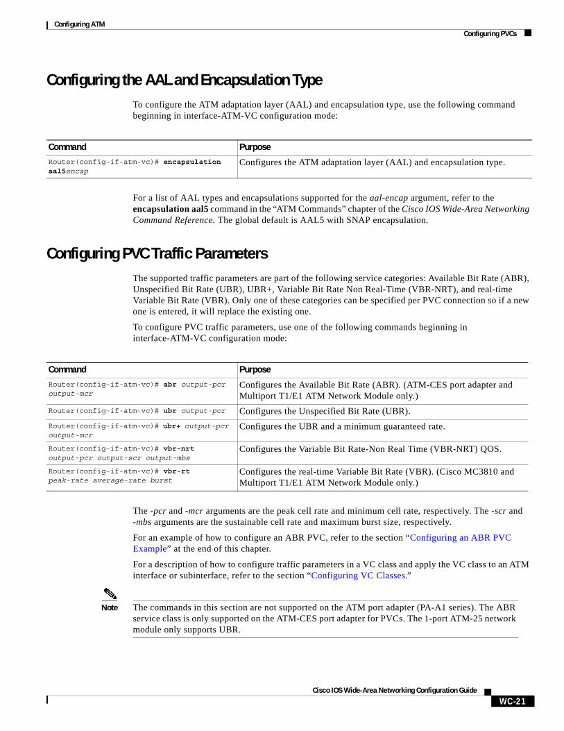
Configuring the AAL and Encapsulation TypeTo configure the ATM adaptation layer (AAL) and encapsulation type, use the following command beginning in interface-ATM-VC configuration mode:
For a list of AAL types and encapsulations supported for the aal-encap argument, refer to the encapsulation aal5 command in the “ATM Commands” chapter of the Cisco IOS Wide-Area Networking Command Reference. The global default is AAL5 with SNAP encapsulation.
Configuring PVC Traffic ParametersThe supported traffic parameters are part of the following service categories: Available Bit Rate (ABR), Unspecified Bit Rate (UBR), UBR+, Variable Bit Rate Non Real-Time (VBR-NRT), and real-time Variable Bit Rate (VBR). Only one of these categories can be specified per PVC connection so if a new one is entered, it will replace the existing one.
To configure PVC traffic parameters, use one of the following commands beginning in interface-ATM-VC configuration mode:
The -pcr and -mcr arguments are the peak cell rate and minimum cell rate, respectively. The -scr and -mbs arguments are the sustainable cell rate and maximum burst size, respectively.
For an example of how to configure an ABR PVC, refer to the section “Configuring an ABR PVC Example” at the end of this chapter.
For a description of how to configure traffic parameters in a VC class and apply the VC class to an ATM interface or subinterface, refer to the section “Configuring VC Classes.”
Note The commands in this section are not supported on the ATM port adapter (PA-A1 series). The ABR service class is only supported on the ATM-CES port adapter for PVCs. The 1-port ATM-25 network module only supports UBR.
Command Purpose
Router(config-if-atm-vc)# encapsulation aal5encap
Configures the ATM adaptation layer (AAL) and encapsulation type.
Command Purpose
Router(config-if-atm-vc)# abr output-pcr output-mcr
Configures the Available Bit Rate (ABR). (ATM-CES port adapter and Multiport T1/E1 ATM Network Module only.)
Router(config-if-atm-vc)# ubr output-pcr Configures the Unspecified Bit Rate (UBR).
Router(config-if-atm-vc)# ubr+ output-pcr output-mcr
Configures the UBR and a minimum guaranteed rate.
Router(config-if-atm-vc)# vbr-nrt output-pcr output-scr output-mbs
Configures the Variable Bit Rate-Non Real Time (VBR-NRT) QOS.
Router(config-if-atm-vc)# vbr-rt peak-rate average-rate burst
Configures the real-time Variable Bit Rate (VBR). (Cisco MC3810 and Multiport T1/E1 ATM Network Module only.)
Configuring ATMConfiguring PVCs
WC-22Cisco IOS Wide-Area Networking Configuration Guide
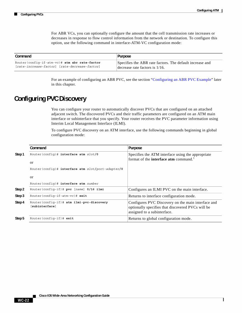
For ABR VCs, you can optionally configure the amount that the cell transmission rate increases or decreases in response to flow control information from the network or destination. To configure this option, use the following command in interface-ATM-VC configuration mode:
For an example of configuring an ABR PVC, see the section “Configuring an ABR PVC Example” later in this chapter.
Configuring PVC DiscoveryYou can configure your router to automatically discover PVCs that are configured on an attached adjacent switch. The discovered PVCs and their traffic parameters are configured on an ATM main interface or subinterface that you specify. Your router receives the PVC parameter information using Interim Local Management Interface (ILMI).
To configure PVC discovery on an ATM interface, use the following commands beginning in global configuration mode:
Command PurposeRouter(config-if-atm-vc)# atm abr rate-factor [rate-increase-factor] [rate-decrease-factor]
Specifies the ABR rate factors. The default increase and decrease rate factors is 1/16.
Command Purpose
Step 1 Router(config)# interface atm slot/0
or
Router(config)# interface atm slot/port-adapter/0
or
Router(config)# interface atm number
Specifies the ATM interface using the appropriate format of the interface atm command.1
Step 2 Router(config-if)# pvc [name] 0/16 ilmi Configures an ILMI PVC on the main interface.
Step 3 Router(config-if-atm-vc)# exit Returns to interface configuration mode.
Step 4 Router(config-if)# atm ilmi-pvc-discovery [subinterface]
Configures PVC Discovery on the main interface and optionally specifies that discovered PVCs will be assigned to a subinterface.
Step 5 Router(config-if)# exit Returns to global configuration mode.
Configuring ATMConfiguring PVCs
WC-23Cisco IOS Wide-Area Networking Configuration Guide
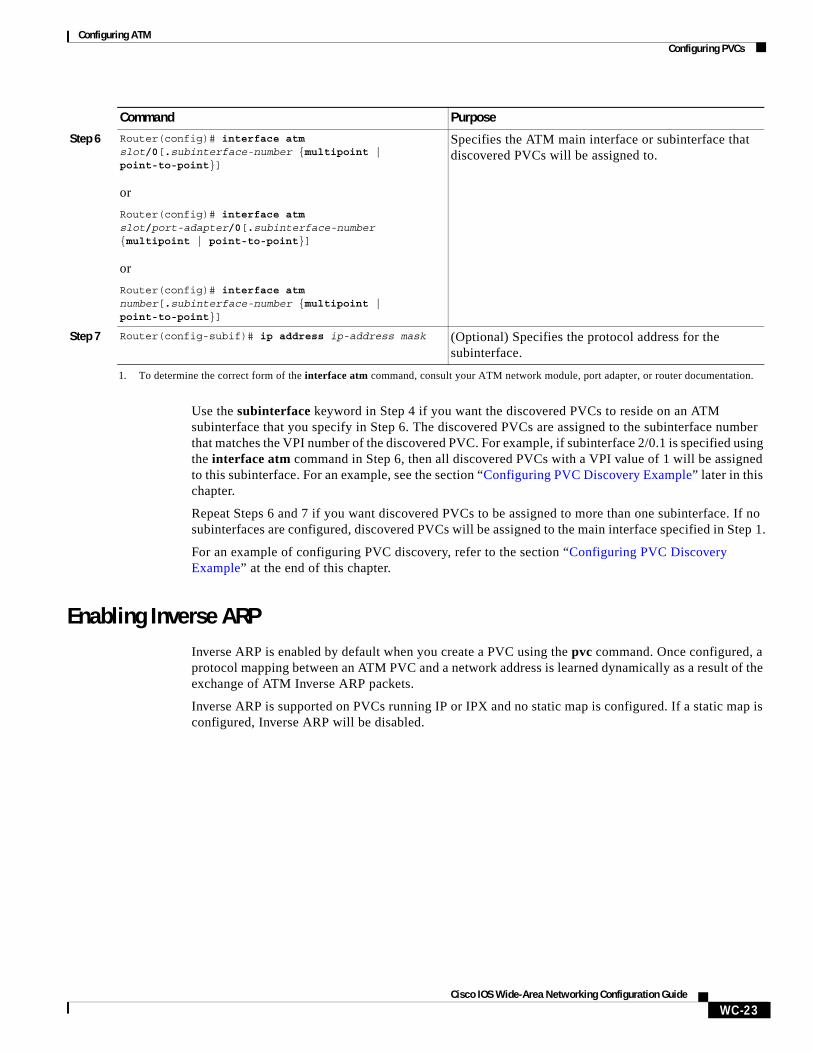
Use the subinterface keyword in Step 4 if you want the discovered PVCs to reside on an ATM subinterface that you specify in Step 6. The discovered PVCs are assigned to the subinterface number that matches the VPI number of the discovered PVC. For example, if subinterface 2/0.1 is specified using the interface atm command in Step 6, then all discovered PVCs with a VPI value of 1 will be assigned to this subinterface. For an example, see the section “Configuring PVC Discovery Example” later in this chapter.
Repeat Steps 6 and 7 if you want discovered PVCs to be assigned to more than one subinterface. If no subinterfaces are configured, discovered PVCs will be assigned to the main interface specified in Step 1.
For an example of configuring PVC discovery, refer to the section “Configuring PVC Discovery Example” at the end of this chapter.
Enabling Inverse ARPInverse ARP is enabled by default when you create a PVC using the pvc command. Once configured, a protocol mapping between an ATM PVC and a network address is learned dynamically as a result of the exchange of ATM Inverse ARP packets.
Inverse ARP is supported on PVCs running IP or IPX and no static map is configured. If a static map is configured, Inverse ARP will be disabled.
Step 6 Router(config)# interface atm slot/0[.subinterface-number {multipoint | point-to-point}]
or
Router(config)# interface atm slot/port-adapter/0[.subinterface-number {multipoint | point-to-point}]
or
Router(config)# interface atm number[.subinterface-number {multipoint | point-to-point}]
Specifies the ATM main interface or subinterface that discovered PVCs will be assigned to.
Step 7 Router(config-subif)# ip address ip-address mask (Optional) Specifies the protocol address for the subinterface.
1. To determine the correct form of the interface atm command, consult your ATM network module, port adapter, or router documentation.
Command Purpose
Configuring ATMConfiguring PVCs
WC-24Cisco IOS Wide-Area Networking Configuration Guide
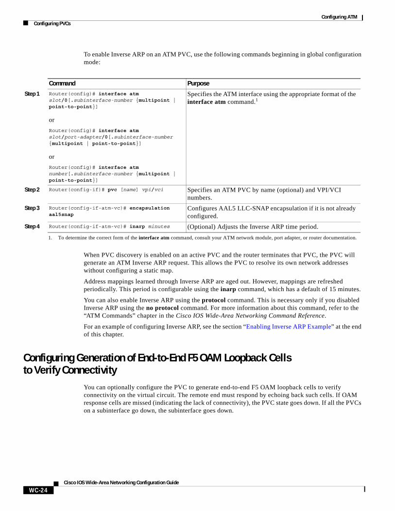
To enable Inverse ARP on an ATM PVC, use the following commands beginning in global configuration mode:
When PVC discovery is enabled on an active PVC and the router terminates that PVC, the PVC will generate an ATM Inverse ARP request. This allows the PVC to resolve its own network addresses without configuring a static map.
Address mappings learned through Inverse ARP are aged out. However, mappings are refreshed periodically. This period is configurable using the inarp command, which has a default of 15 minutes.
You can also enable Inverse ARP using the protocol command. This is necessary only if you disabled Inverse ARP using the no protocol command. For more information about this command, refer to the “ATM Commands” chapter in the Cisco IOS Wide-Area Networking Command Reference.
For an example of configuring Inverse ARP, see the section “Enabling Inverse ARP Example” at the end of this chapter.
Configuring Generation of End-to-End F5 OAM Loopback Cells to Verify Connectivity
You can optionally configure the PVC to generate end-to-end F5 OAM loopback cells to verify connectivity on the virtual circuit. The remote end must respond by echoing back such cells. If OAM response cells are missed (indicating the lack of connectivity), the PVC state goes down. If all the PVCs on a subinterface go down, the subinterface goes down.
Command Purpose
Step 1 Router(config)# interface atm slot/0[.subinterface-number {multipoint | point-to-point}]
or
Router(config)# interface atm slot/port-adapter/0[.subinterface-number {multipoint | point-to-point}]
or
Router(config)# interface atm number[.subinterface-number {multipoint | point-to-point}]
Specifies the ATM interface using the appropriate format of the interface atm command.1
1. To determine the correct form of the interface atm command, consult your ATM network module, port adapter, or router documentation.
Step 2 Router(config-if)# pvc [name] vpi/vci Specifies an ATM PVC by name (optional) and VPI/VCI numbers.
Step 3 Router(config-if-atm-vc)# encapsulation aal5snap
Configures AAL5 LLC-SNAP encapsulation if it is not already configured.
Step 4 Router(config-if-atm-vc)# inarp minutes (Optional) Adjusts the Inverse ARP time period.
Configuring ATMConfiguring PVCs
WC-25Cisco IOS Wide-Area Networking Configuration Guide
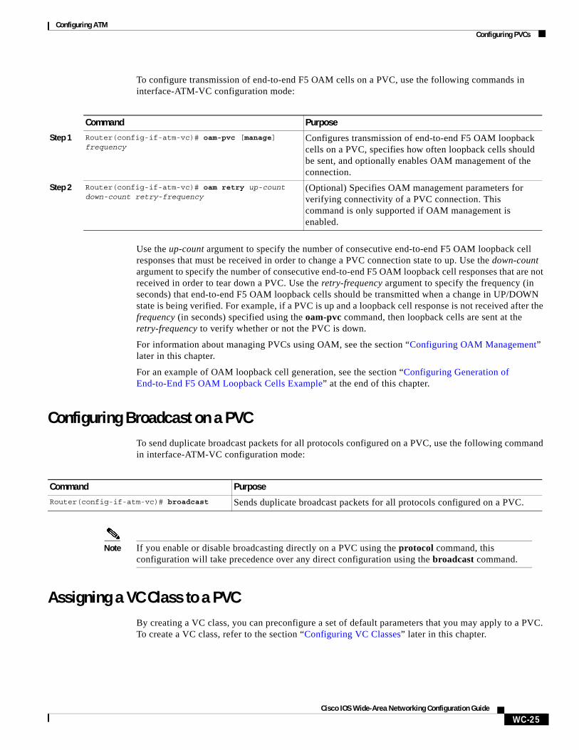
To configure transmission of end-to-end F5 OAM cells on a PVC, use the following commands in interface-ATM-VC configuration mode:
Use the up-count argument to specify the number of consecutive end-to-end F5 OAM loopback cell responses that must be received in order to change a PVC connection state to up. Use the down-count argument to specify the number of consecutive end-to-end F5 OAM loopback cell responses that are not received in order to tear down a PVC. Use the retry-frequency argument to specify the frequency (in seconds) that end-to-end F5 OAM loopback cells should be transmitted when a change in UP/DOWN state is being verified. For example, if a PVC is up and a loopback cell response is not received after the frequency (in seconds) specified using the oam-pvc command, then loopback cells are sent at the retry-frequency to verify whether or not the PVC is down.
For information about managing PVCs using OAM, see the section “Configuring OAM Management” later in this chapter.
For an example of OAM loopback cell generation, see the section “Configuring Generation of End-to-End F5 OAM Loopback Cells Example” at the end of this chapter.
Configuring Broadcast on a PVCTo send duplicate broadcast packets for all protocols configured on a PVC, use the following command in interface-ATM-VC configuration mode:
Note If you enable or disable broadcasting directly on a PVC using the protocol command, this configuration will take precedence over any direct configuration using the broadcast command.
Assigning a VC Class to a PVCBy creating a VC class, you can preconfigure a set of default parameters that you may apply to a PVC. To create a VC class, refer to the section “Configuring VC Classes” later in this chapter.
Command Purpose
Step 1 Router(config-if-atm-vc)# oam-pvc [manage] frequency
Configures transmission of end-to-end F5 OAM loopback cells on a PVC, specifies how often loopback cells should be sent, and optionally enables OAM management of the connection.
Step 2 Router(config-if-atm-vc)# oam retry up-count down-count retry-frequency
(Optional) Specifies OAM management parameters for verifying connectivity of a PVC connection. This command is only supported if OAM management is enabled.
Command PurposeRouter(config-if-atm-vc)# broadcast Sends duplicate broadcast packets for all protocols configured on a PVC.
Configuring ATMConfiguring PVCs
WC-26Cisco IOS Wide-Area Networking Configuration Guide
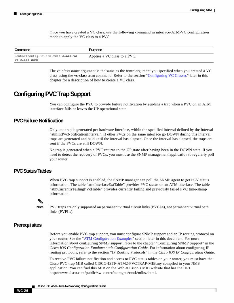
Once you have created a VC class, use the following command in interface-ATM-VC configuration mode to apply the VC class to a PVC:
The vc-class-name argument is the same as the name argument you specified when you created a VC class using the vc-class atm command. Refer to the section “Configuring VC Classes” later in this chapter for a description of how to create a VC class.
Configuring PVC Trap SupportYou can configure the PVC to provide failure notification by sending a trap when a PVC on an ATM interface fails or leaves the UP operational state.
PVC Failure Notification
Only one trap is generated per hardware interface, within the specified interval defined by the interval “atmIntPvcNotificationInterval”. If other PVCs on the same interface go DOWN during this interval, traps are generated and held until the interval has elapsed. Once the interval has elapsed, the traps are sent if the PVCs are still DOWN.
No trap is generated when a PVC returns to the UP state after having been in the DOWN state. If you need to detect the recovery of PVCs, you must use the SNMP management application to regularly poll your router.
PVC Status Tables
When PVC trap support is enabled, the SNMP manager can poll the SNMP agent to get PCV status information. The table “atmInterfaceExtTable” provides PVC status on an ATM interface. The table “atmCurrentlyFailingPVclTable” provides currently failing and previously failed PVC time-stamp information.
Note PVC traps are only supported on permanent virtual circuit links (PVCLs), not permanent virtual path links (PVPLs).
Prerequisites
Before you enable PVC trap support, you must configure SNMP support and an IP routing protocol on your router. See the “ATM Configuration Examples” section later in this document. For more information about configuring SNMP support, refer to the chapter “Configuring SNMP Support” in the Cisco IOS Configuration Fundamentals Configuration Guide. For information about configuring IP routing protocols, refer to the section “IP Routing Protocols” in the Cisco IOS IP Configuration Guide.
To receive PVC failure notification and access to PVC status tables on your router, you must have the Cisco PVC trap MIB called CISCO-IETF-ATM2-PVCTRAP-MIB.my compiled in your NMS application. You can find this MIB on the Web at Cisco’s MIB website that has the URL http://www.cisco.com/public/sw-center/netmgmt/cmtk/mibs.shtml.
Command PurposeRouter(config-if-atm-vc)# class-vc vc-class-name
Applies a VC class to a PVC.
Configuring ATMConfiguring SVCs
WC-27Cisco IOS Wide-Area Networking Configuration Guide
Enabling PVC Trap Support
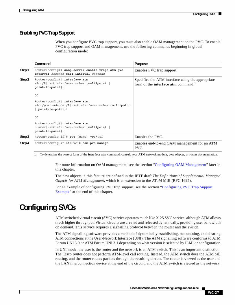
When you configure PVC trap support, you must also enable OAM management on the PVC. To enable PVC trap support and OAM management, use the following commands beginning in global configuration mode:
For more information on OAM management, see the section “Configuring OAM Management” later in this chapter.
The new objects in this feature are defined in the IETF draft The Definitions of Supplemental Managed Objects for ATM Management, which is an extension to the AToM MIB (RFC 1695).
For an example of configuring PVC trap support, see the section “Configuring PVC Trap Support Example” at the end of this chapter.
Configuring SVCsATM switched virtual circuit (SVC) service operates much like X.25 SVC service, although ATM allows much higher throughput. Virtual circuits are created and released dynamically, providing user bandwidth on demand. This service requires a signalling protocol between the router and the switch.
The ATM signalling software provides a method of dynamically establishing, maintaining, and clearing ATM connections at the User-Network Interface (UNI). The ATM signalling software conforms to ATM Forum UNI 3.0 or ATM Forum UNI 3.1 depending on what version is selected by ILMI or configuration.
In UNI mode, the user is the router and the network is an ATM switch. This is an important distinction. The Cisco router does not perform ATM-level call routing. Instead, the ATM switch does the ATM call routing, and the router routes packets through the resulting circuit. The router is viewed as the user and the LAN interconnection device at the end of the circuit, and the ATM switch is viewed as the network.
Command Purpose
Step 1 Router(config)# snmp-server enable traps atm pvc interval seconds fail-interval seconds
Enables PVC trap support.
Step 2 Router(config)# interface atm slot/0[.subinterface-number {multipoint | point-to-point}]
or
Router(config)# interface atm slot/port-adapter/0[.subinterface-number {multipoint | point-to-point}]
or
Router(config)# interface atm number[.subinterface-number {multipoint | point-to-point}]
Specifies the ATM interface using the appropriate form of the interface atm command.1
1. To determine the correct form of the interface atm command, consult your ATM network module, port adapter, or router documentation.
Step 3 Router(config-if)# pvc [name] vpi/vci Enables the PVC.
Step 4 Router(config-if-atm-vc)# oam-pvc manage Enables end-to-end OAM management for an ATM PVC.
Configuring ATMConfiguring SVCs
WC-28Cisco IOS Wide-Area Networking Configuration Guide
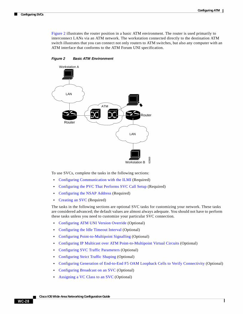
Figure 2 illustrates the router position in a basic ATM environment. The router is used primarily to interconnect LANs via an ATM network. The workstation connected directly to the destination ATM switch illustrates that you can connect not only routers to ATM switches, but also any computer with an ATM interface that conforms to the ATM Forum UNI specification.
Figure 2 Basic ATM Environment
To use SVCs, complete the tasks in the following sections:
• Configuring Communication with the ILMI (Required)
• Configuring the PVC That Performs SVC Call Setup (Required)
• Configuring the NSAP Address (Required)
• Creating an SVC (Required)
The tasks in the following sections are optional SVC tasks for customizing your network. These tasks are considered advanced; the default values are almost always adequate. You should not have to perform these tasks unless you need to customize your particular SVC connection.
• Configuring ATM UNI Version Override (Optional)
• Configuring the Idle Timeout Interval (Optional)
• Configuring Point-to-Multipoint Signalling (Optional)
• Configuring IP Multicast over ATM Point-to-Multipoint Virtual Circuits (Optional)
• Configuring SVC Traffic Parameters (Optional)
• Configuring Strict Traffic Shaping (Optional)
• Configuring Generation of End-to-End F5 OAM Loopback Cells to Verify Connectivity (Optional)
• Configuring Broadcast on an SVC (Optional)
• Assigning a VC Class to an SVC (Optional)
Router
Router
ATM
LAN
LAN
Workstation A
Workstation B 6286
9
Configuring ATMConfiguring SVCs
WC-29Cisco IOS Wide-Area Networking Configuration Guide
• Configuring SSCOP (Optional)
• Closing an SVC (Optional)
Note SVCs are not supported on the 1-port ATM-25 network module.
Configuring Communication with the ILMIIn an SVC environment, you must configure a PVC for communication with the Integrated Local Management Interface (ILMI) so the router can receive SNMP traps and new network prefixes. The recommended vpi and vci values for the ILMI PVC are 0 and 16, respectively. To configure ILMI communication, use the following command in interface configuration mode:
Note This ILMI PVC can be set up only on an ATM main interface, not on ATM subinterfaces.
Once you have configured an ILMI PVC, you can optionally enable the ILMI keepalive function by using the following command in interface configuration mode:
No other configuration steps are required.
ILMI address registration for receipt of SNMP traps and new network prefixes is enabled by default. The ILMI keepalive function is disabled by default; when enabled, the default interval between keepalives is 3 seconds.
For an example of configuring ILMI, see the section “Configuring Communication with the ILMI Example” in the “ATM Configuration Examples” section at the end of this chapter.
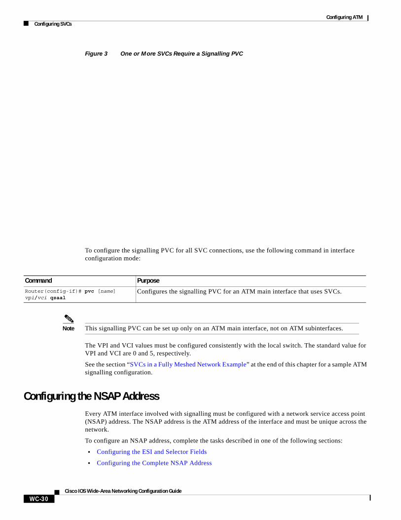
Configuring the PVC That Performs SVC Call SetupUnlike X.25 service, which uses in-band signalling (connection establishment done on the same circuit as data transfer), ATM uses out-of-band signalling. One dedicated PVC exists between the router and the ATM switch, over which all SVC call establishment and call termination requests flow. After the call is established, data transfer occurs over the SVC, from router to router. The signalling that accomplishes the call setup and teardown is called Layer 3 signalling or the Q.2931 protocol.
For out-of-band signalling, a signalling PVC must be configured before any SVCs can be set up. Figure 3 illustrates that a signalling PVC from the source router to the ATM switch is used to set up two SVCs. This is a fully meshed network; workstations A, B, and C all can communicate with each other.
Command Purpose
Router(config-if)# pvc [name] 0/16 ilmi Creates an ILMI PVC on an ATM main interface.
Command Purpose
Router(config-if)# atm ilmi-keepalive [seconds]
Enables ILMI keepalives and sets the interval between keepalives.
Configuring ATMConfiguring SVCs
WC-30Cisco IOS Wide-Area Networking Configuration Guide
Figure 3 One or More SVCs Require a Signalling PVC
To configure the signalling PVC for all SVC connections, use the following command in interface configuration mode:
Note This signalling PVC can be set up only on an ATM main interface, not on ATM subinterfaces.
The VPI and VCI values must be configured consistently with the local switch. The standard value for VPI and VCI are 0 and 5, respectively.
See the section “SVCs in a Fully Meshed Network Example” at the end of this chapter for a sample ATM signalling configuration.
Configuring the NSAP AddressEvery ATM interface involved with signalling must be configured with a network service access point (NSAP) address. The NSAP address is the ATM address of the interface and must be unique across the network.
To configure an NSAP address, complete the tasks described in one of the following sections:
• Configuring the ESI and Selector Fields
• Configuring the Complete NSAP Address
Command Purpose
Router(config-if)# pvc [name] vpi/vci qsaal
Configures the signalling PVC for an ATM main interface that uses SVCs.
Configuring ATMConfiguring SVCs
WC-31Cisco IOS Wide-Area Networking Configuration Guide
Configuring the ESI and Selector Fields
If the switch is capable of delivering the NSAP address prefix to the router by using ILMI, and the router is configured with a PVC for communication with the switch via ILMI, you can configure the endstation ID (ESI) and selector fields using the atm esi-address command. The atm esi-address command allows you to configure the ATM address by entering the ESI (12 hexadecimal characters) and the selector byte (2 hexadecimal characters). The NSAP prefix (26 hexadecimal characters) is provided by the ATM switch.
To configure the router to get the NSAP prefix from the switch and use locally entered values for the remaining fields of the address, use the following commands beginning in interface configuration mode:
The recommended vpi and vci values for the ILMI PVC are 0 and 16, respectively.
You can also specify a keepalive interval for the ILMI PVC. See the “Configuring Communication with the ILMI” section earlier in this chapter for more information.
To see an example of setting up the ILMI PVC and assigning the ESI and selector fields of an NSAP address, see the section “SVCs with Multipoint Signalling Example” at the end of this chapter.
Configuring the Complete NSAP Address
When you configure the ATM NSAP address manually, you must enter the entire address in hexadecimal format because each digit entered represents a hexadecimal digit. To represent the complete NSAP address, you must enter 40 hexadecimal digits in the following format:
XX.XXXX.XX.XXXXXX.XXXX.XXXX.XXXX.XXXX.XXXX.XXXX.XX
Note All ATM NSAP addresses may be entered in the dotted hexadecimal format shown, which conforms to the UNI specification. The dotted method provides some validation that the address is a legal value. If you know your address format is correct, the dots may be omitted.
Because the interface has no default NSAP address, you must configure the NSAP address for SVCs. To set the ATM interface’s source NSAP address, use the following command in interface configuration mode:
The atm nsap-address and atm esi-address commands are mutually exclusive. Configuring the router with the atm nsap-address command negates the atm esi-address setting, and vice versa. For information about using the atm esi-address command, see the preceding section “Configuring the ESI and Selector Fields.”
Command Purpose
Step 1 Router(config-if)# pvc [name] 0/16 ilmi
Configures an ILMI PVC on an ATM main interface for communicating with the switch by using ILMI.
Step 2 Router(config-if-atm-vc)# exit Returns to interface configuration mode.
Step 3 Router(config-if)# atm esi-address esi.selector
Enters the ESI and selector fields of the NSAP address.
Command Purpose
Router(config-if)# atm nsap-address nsap-address
Configures the ATM NSAP address for an interface.
Configuring ATMConfiguring SVCs
WC-32Cisco IOS Wide-Area Networking Configuration Guide
See an example of assigning an NSAP address to an ATM interface in the section “ATM NSAP Address Example” at the end of this chapter.
Creating an SVCTo create an SVC, use the following commands beginning in interface configuration mode:
Once you specify a name for an SVC, you can reenter interface-ATM-VC configuration mode by simply entering the svc name command; you can remove an SVC configuration by entering the no svc name command.
For a list of AAL types and encapsulations supported for the aal-encap argument, refer to the encapsulation aal5 command in the “ATM Commands” chapter of the Cisco IOS Wide-Area Networking Command Reference. The default is AAL5 with SNAP encapsulation.
Configuring ATM UNI Version OverrideNormally, when ILMI link autodetermination is enabled on the interface and is successful, the router takes the user-network interface (UNI) version returned by ILMI. If the ILMI link autodetermination process is unsuccessful or ILMI is disabled, the UNI version defaults to 3.0. You can override this default by using the atm uni-version command. The no form of the command sets the UNI version to the one returned by ILMI if ILMI is enabled and the link autodetermination is successful. Otherwise, the UNI version will revert to 3.0. To override the ATM UNI version used by the router, use the following command in interface configuration mode:
No other configuration steps are required.
Configuring the Idle Timeout IntervalYou can specify an interval of inactivity after which any idle SVC on an interface is torn down. This timeout interval might help control costs and free router memory and other resources for other uses.
Command Purpose
Step 1 Router(config-if)# svc [name] nsap address Creates an SVC and specifies the destination NSAP address.
Step 2 Router(config-if-atm-vc)# encapsulation aal5encap (Optional) Configures the ATM adaptation layer (AAL) and encapsulation type.
Step 3 Router(config-if-atm-vc)# protocol protocol protocol-address [[no] broadcast]
Maps a protocol address to an SVC.
Command PurposeRouter(config-if)# atm uni-version version-number
Overrides UNI version used by router.
Configuring ATMConfiguring SVCs
WC-33Cisco IOS Wide-Area Networking Configuration Guide
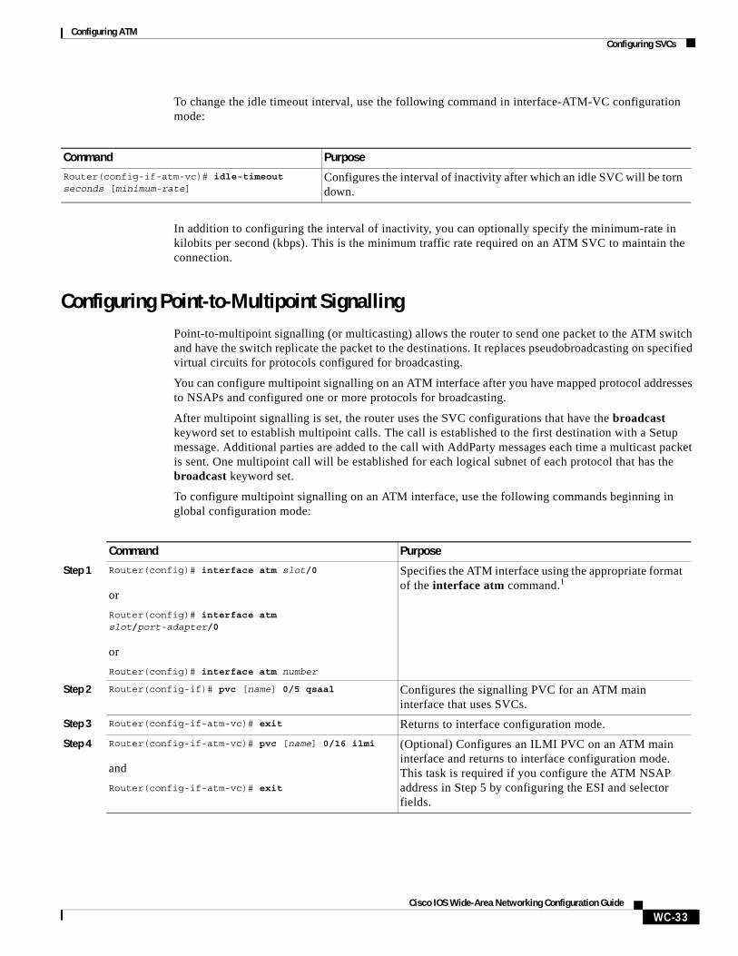
To change the idle timeout interval, use the following command in interface-ATM-VC configuration mode:
In addition to configuring the interval of inactivity, you can optionally specify the minimum-rate in kilobits per second (kbps). This is the minimum traffic rate required on an ATM SVC to maintain the connection.
Configuring Point-to-Multipoint SignallingPoint-to-multipoint signalling (or multicasting) allows the router to send one packet to the ATM switch and have the switch replicate the packet to the destinations. It replaces pseudobroadcasting on specified virtual circuits for protocols configured for broadcasting.
You can configure multipoint signalling on an ATM interface after you have mapped protocol addresses to NSAPs and configured one or more protocols for broadcasting.
After multipoint signalling is set, the router uses the SVC configurations that have the broadcast keyword set to establish multipoint calls. The call is established to the first destination with a Setup message. Additional parties are added to the call with AddParty messages each time a multicast packet is sent. One multipoint call will be established for each logical subnet of each protocol that has the broadcast keyword set.
To configure multipoint signalling on an ATM interface, use the following commands beginning in global configuration mode:
Command PurposeRouter(config-if-atm-vc)# idle-timeout seconds [minimum-rate]
Configures the interval of inactivity after which an idle SVC will be torn down.
Command Purpose
Step 1 Router(config)# interface atm slot/0
or
Router(config)# interface atm slot/port-adapter/0
or
Router(config)# interface atm number
Specifies the ATM interface using the appropriate format of the interface atm command.1
Step 2 Router(config-if)# pvc [name] 0/5 qsaal Configures the signalling PVC for an ATM main interface that uses SVCs.
Step 3 Router(config-if-atm-vc)# exit Returns to interface configuration mode.
Step 4 Router(config-if-atm-vc)# pvc [name] 0/16 ilmi
and
Router(config-if-atm-vc)# exit
(Optional) Configures an ILMI PVC on an ATM main interface and returns to interface configuration mode. This task is required if you configure the ATM NSAP address in Step 5 by configuring the ESI and selector fields.
Configuring ATMConfiguring SVCs
WC-34Cisco IOS Wide-Area Networking Configuration Guide
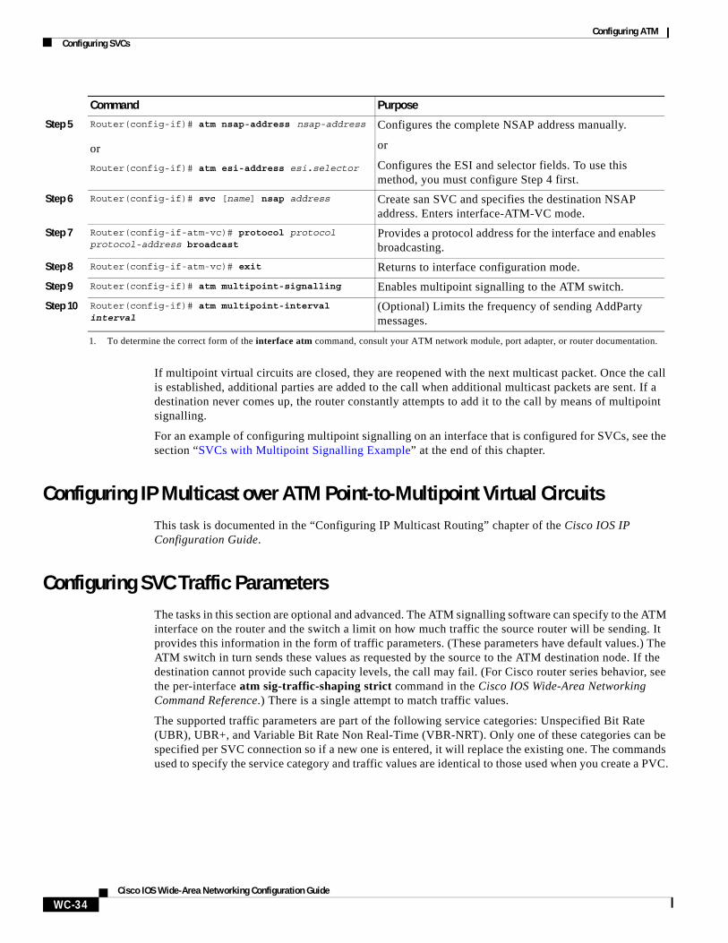
If multipoint virtual circuits are closed, they are reopened with the next multicast packet. Once the call is established, additional parties are added to the call when additional multicast packets are sent. If a destination never comes up, the router constantly attempts to add it to the call by means of multipoint signalling.
For an example of configuring multipoint signalling on an interface that is configured for SVCs, see the section “SVCs with Multipoint Signalling Example” at the end of this chapter.
Configuring IP Multicast over ATM Point-to-Multipoint Virtual CircuitsThis task is documented in the “Configuring IP Multicast Routing” chapter of the Cisco IOS IP Configuration Guide.
Configuring SVC Traffic ParametersThe tasks in this section are optional and advanced. The ATM signalling software can specify to the ATM interface on the router and the switch a limit on how much traffic the source router will be sending. It provides this information in the form of traffic parameters. (These parameters have default values.) The ATM switch in turn sends these values as requested by the source to the ATM destination node. If the destination cannot provide such capacity levels, the call may fail. (For Cisco router series behavior, see the per-interface atm sig-traffic-shaping strict command in the Cisco IOS Wide-Area Networking Command Reference.) There is a single attempt to match traffic values.
The supported traffic parameters are part of the following service categories: Unspecified Bit Rate (UBR), UBR+, and Variable Bit Rate Non Real-Time (VBR-NRT). Only one of these categories can be specified per SVC connection so if a new one is entered, it will replace the existing one. The commands used to specify the service category and traffic values are identical to those used when you create a PVC.
Step 5 Router(config-if)# atm nsap-address nsap-address
or
Router(config-if)# atm esi-address esi.selector
Configures the complete NSAP address manually.
or
Configures the ESI and selector fields. To use this method, you must configure Step 4 first.
Step 6 Router(config-if)# svc [name] nsap address Create san SVC and specifies the destination NSAP address. Enters interface-ATM-VC mode.
Step 7 Router(config-if-atm-vc)# protocol protocol protocol-address broadcast
Provides a protocol address for the interface and enables broadcasting.
Step 8 Router(config-if-atm-vc)# exit Returns to interface configuration mode.
Step 9 Router(config-if)# atm multipoint-signalling Enables multipoint signalling to the ATM switch.
Step 10 Router(config-if)# atm multipoint-interval interval
(Optional) Limits the frequency of sending AddParty messages.
1. To determine the correct form of the interface atm command, consult your ATM network module, port adapter, or router documentation.
Command Purpose
Configuring ATMConfiguring SVCs
WC-35Cisco IOS Wide-Area Networking Configuration Guide
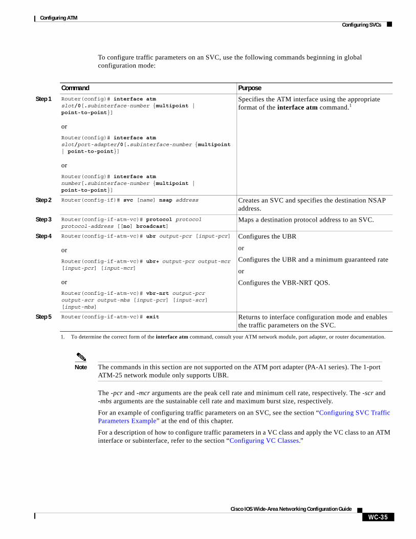
To configure traffic parameters on an SVC, use the following commands beginning in global configuration mode:
Note The commands in this section are not supported on the ATM port adapter (PA-A1 series). The 1-port ATM-25 network module only supports UBR.
The -pcr and -mcr arguments are the peak cell rate and minimum cell rate, respectively. The -scr and -mbs arguments are the sustainable cell rate and maximum burst size, respectively.
For an example of configuring traffic parameters on an SVC, see the section “Configuring SVC Traffic Parameters Example” at the end of this chapter.
For a description of how to configure traffic parameters in a VC class and apply the VC class to an ATM interface or subinterface, refer to the section “Configuring VC Classes.”
Command Purpose
Step 1 Router(config)# interface atm slot/0[.subinterface-number {multipoint | point-to-point}]
or
Router(config)# interface atm slot/port-adapter/0[.subinterface-number {multipoint | point-to-point}]
or
Router(config)# interface atm number[.subinterface-number {multipoint | point-to-point}]
Specifies the ATM interface using the appropriate format of the interface atm command.1
1. To determine the correct form of the interface atm command, consult your ATM network module, port adapter, or router documentation.
Step 2 Router(config-if)# svc [name] nsap address Creates an SVC and specifies the destination NSAP address.
Step 3 Router(config-if-atm-vc)# protocol protocol protocol-address [[no] broadcast]
Maps a destination protocol address to an SVC.
Step 4 Router(config-if-atm-vc)# ubr output-pcr [input-pcr]
or
Router(config-if-atm-vc)# ubr+ output-pcr output-mcr [input-pcr] [input-mcr]
or
Router(config-if-atm-vc)# vbr-nrt output-pcr output-scr output-mbs [input-pcr] [input-scr] [input-mbs]
Configures the UBR
or
Configures the UBR and a minimum guaranteed rate
or
Configures the VBR-NRT QOS.
Step 5 Router(config-if-atm-vc)# exit Returns to interface configuration mode and enables the traffic parameters on the SVC.
Configuring ATMConfiguring SVCs
WC-36Cisco IOS Wide-Area Networking Configuration Guide
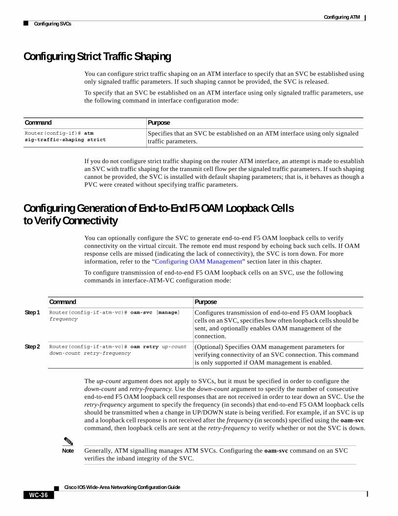
Configuring Strict Traffic ShapingYou can configure strict traffic shaping on an ATM interface to specify that an SVC be established using only signaled traffic parameters. If such shaping cannot be provided, the SVC is released.
To specify that an SVC be established on an ATM interface using only signaled traffic parameters, use the following command in interface configuration mode:
If you do not configure strict traffic shaping on the router ATM interface, an attempt is made to establish an SVC with traffic shaping for the transmit cell flow per the signaled traffic parameters. If such shaping cannot be provided, the SVC is installed with default shaping parameters; that is, it behaves as though a PVC were created without specifying traffic parameters.
Configuring Generation of End-to-End F5 OAM Loopback Cells to Verify Connectivity
You can optionally configure the SVC to generate end-to-end F5 OAM loopback cells to verify connectivity on the virtual circuit. The remote end must respond by echoing back such cells. If OAM response cells are missed (indicating the lack of connectivity), the SVC is torn down. For more information, refer to the “Configuring OAM Management” section later in this chapter.
To configure transmission of end-to-end F5 OAM loopback cells on an SVC, use the following commands in interface-ATM-VC configuration mode:
The up-count argument does not apply to SVCs, but it must be specified in order to configure the down-count and retry-frequency. Use the down-count argument to specify the number of consecutive end-to-end F5 OAM loopback cell responses that are not received in order to tear down an SVC. Use the retry-frequency argument to specify the frequency (in seconds) that end-to-end F5 OAM loopback cells should be transmitted when a change in UP/DOWN state is being verified. For example, if an SVC is up and a loopback cell response is not received after the frequency (in seconds) specified using the oam-svc command, then loopback cells are sent at the retry-frequency to verify whether or not the SVC is down.
Note Generally, ATM signalling manages ATM SVCs. Configuring the oam-svc command on an SVC verifies the inband integrity of the SVC.
Command Purpose
Router(config-if)# atm sig-traffic-shaping strict
Specifies that an SVC be established on an ATM interface using only signaled traffic parameters.
Command Purpose
Step 1 Router(config-if-atm-vc)# oam-svc [manage] frequency
Configures transmission of end-to-end F5 OAM loopback cells on an SVC, specifies how often loopback cells should be sent, and optionally enables OAM management of the connection.
Step 2 Router(config-if-atm-vc)# oam retry up-count down-count retry-frequency
(Optional) Specifies OAM management parameters for verifying connectivity of an SVC connection. This command is only supported if OAM management is enabled.
Configuring ATMConfiguring SVCs
WC-37Cisco IOS Wide-Area Networking Configuration Guide
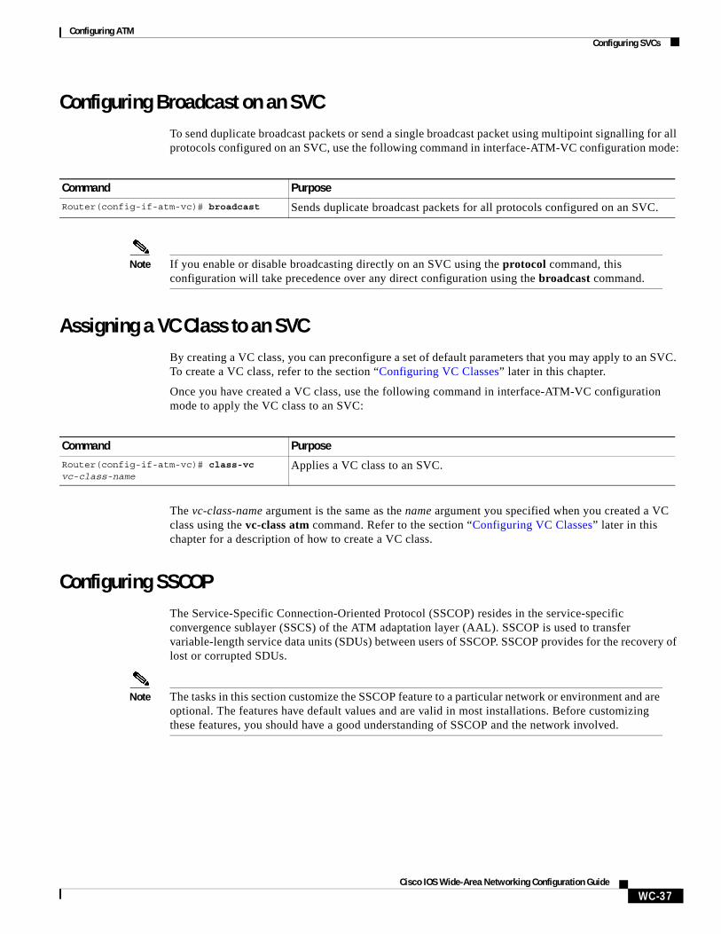
Configuring Broadcast on an SVCTo send duplicate broadcast packets or send a single broadcast packet using multipoint signalling for all protocols configured on an SVC, use the following command in interface-ATM-VC configuration mode:
Note If you enable or disable broadcasting directly on an SVC using the protocol command, this configuration will take precedence over any direct configuration using the broadcast command.
Assigning a VC Class to an SVCBy creating a VC class, you can preconfigure a set of default parameters that you may apply to an SVC. To create a VC class, refer to the section “Configuring VC Classes” later in this chapter.
Once you have created a VC class, use the following command in interface-ATM-VC configuration mode to apply the VC class to an SVC:
The vc-class-name argument is the same as the name argument you specified when you created a VC class using the vc-class atm command. Refer to the section “Configuring VC Classes” later in this chapter for a description of how to create a VC class.
Configuring SSCOPThe Service-Specific Connection-Oriented Protocol (SSCOP) resides in the service-specific convergence sublayer (SSCS) of the ATM adaptation layer (AAL). SSCOP is used to transfer variable-length service data units (SDUs) between users of SSCOP. SSCOP provides for the recovery of lost or corrupted SDUs.
Note The tasks in this section customize the SSCOP feature to a particular network or environment and are optional. The features have default values and are valid in most installations. Before customizing these features, you should have a good understanding of SSCOP and the network involved.
Command Purpose
Router(config-if-atm-vc)# broadcast Sends duplicate broadcast packets for all protocols configured on an SVC.
Command Purpose
Router(config-if-atm-vc)# class-vc vc-class-name
Applies a VC class to an SVC.
Configuring ATMConfiguring SVCs
WC-38Cisco IOS Wide-Area Networking Configuration Guide
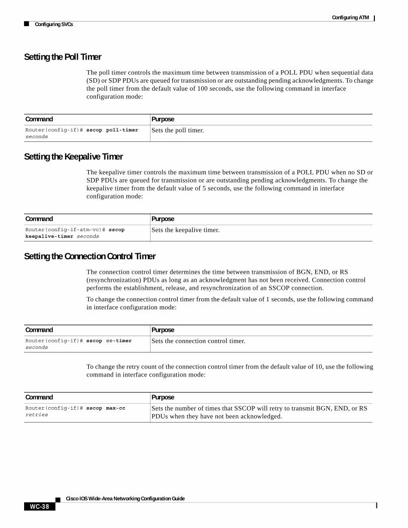
Setting the Poll Timer
The poll timer controls the maximum time between transmission of a POLL PDU when sequential data (SD) or SDP PDUs are queued for transmission or are outstanding pending acknowledgments. To change the poll timer from the default value of 100 seconds, use the following command in interface configuration mode:
Setting the Keepalive Timer
The keepalive timer controls the maximum time between transmission of a POLL PDU when no SD or SDP PDUs are queued for transmission or are outstanding pending acknowledgments. To change the keepalive timer from the default value of 5 seconds, use the following command in interface configuration mode:
Setting the Connection Control Timer
The connection control timer determines the time between transmission of BGN, END, or RS (resynchronization) PDUs as long as an acknowledgment has not been received. Connection control performs the establishment, release, and resynchronization of an SSCOP connection.
To change the connection control timer from the default value of 1 seconds, use the following command in interface configuration mode:
To change the retry count of the connection control timer from the default value of 10, use the following command in interface configuration mode:
Command Purpose
Router(config-if)# sscop poll-timer seconds
Sets the poll timer.
Command Purpose
Router(config-if-atm-vc)# sscop keepalive-timer seconds
Sets the keepalive timer.
Command Purpose
Router(config-if)# sscop cc-timer seconds
Sets the connection control timer.
Command Purpose
Router(config-if)# sscop max-cc retries
Sets the number of times that SSCOP will retry to transmit BGN, END, or RS PDUs when they have not been acknowledged.
Configuring ATMConfiguring VC Classes
WC-39Cisco IOS Wide-Area Networking Configuration Guide
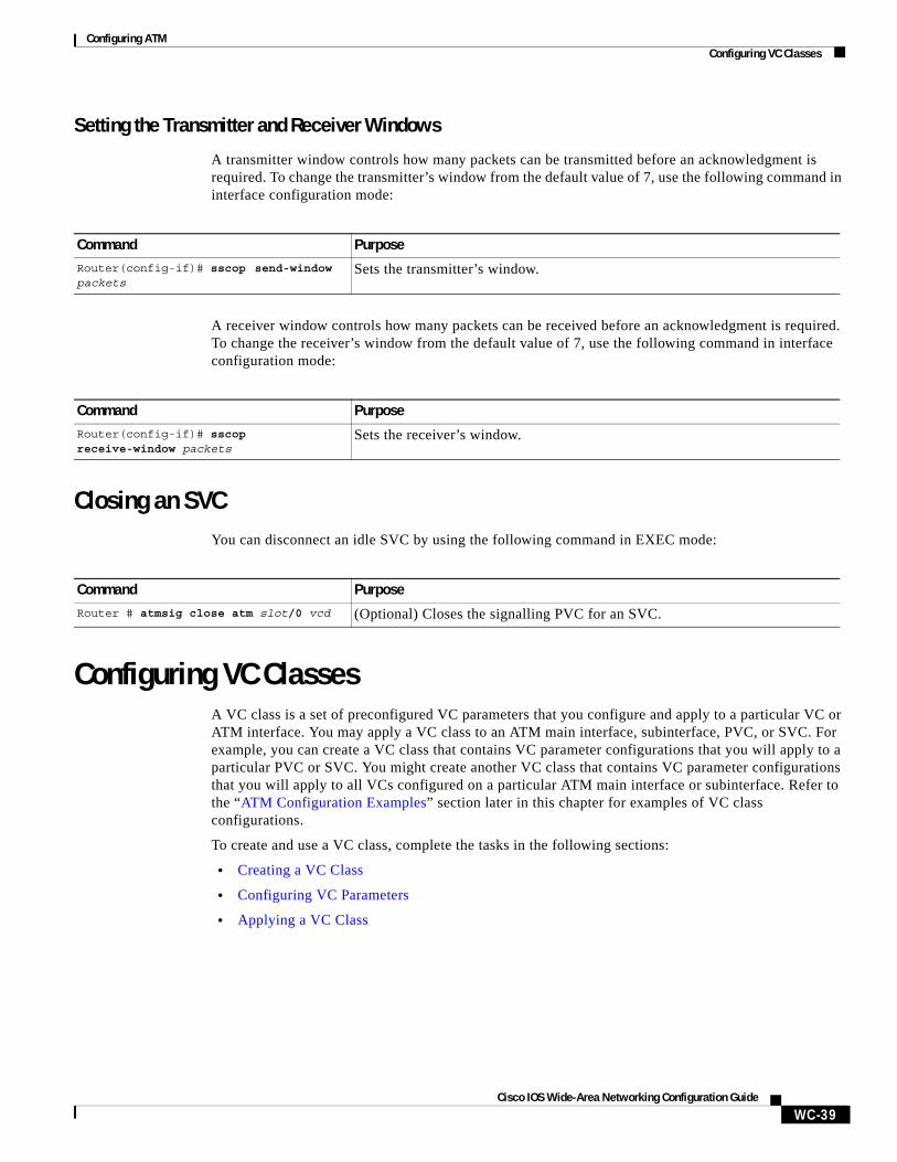
Setting the Transmitter and Receiver Windows
A transmitter window controls how many packets can be transmitted before an acknowledgment is required. To change the transmitter’s window from the default value of 7, use the following command in interface configuration mode:
A receiver window controls how many packets can be received before an acknowledgment is required. To change the receiver’s window from the default value of 7, use the following command in interface configuration mode:
Closing an SVCYou can disconnect an idle SVC by using the following command in EXEC mode:
Configuring VC ClassesA VC class is a set of preconfigured VC parameters that you configure and apply to a particular VC or ATM interface. You may apply a VC class to an ATM main interface, subinterface, PVC, or SVC. For example, you can create a VC class that contains VC parameter configurations that you will apply to a particular PVC or SVC. You might create another VC class that contains VC parameter configurations that you will apply to all VCs configured on a particular ATM main interface or subinterface. Refer to the “ATM Configuration Examples” section later in this chapter for examples of VC class configurations.
To create and use a VC class, complete the tasks in the following sections:
• Creating a VC Class
• Configuring VC Parameters
• Applying a VC Class
Command Purpose
Router(config-if)# sscop send-window packets
Sets the transmitter’s window.
Command Purpose
Router(config-if)# sscop receive-window packets
Sets the receiver’s window.
Command Purpose
Router # atmsig close atm slot/0 vcd (Optional) Closes the signalling PVC for an SVC.
Configuring ATMConfiguring VC Classes
WC-40Cisco IOS Wide-Area Networking Configuration Guide
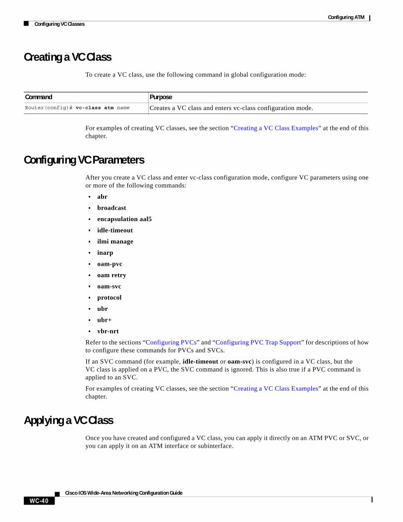
Creating a VC ClassTo create a VC class, use the following command in global configuration mode:
For examples of creating VC classes, see the section “Creating a VC Class Examples” at the end of this chapter.
Configuring VC ParametersAfter you create a VC class and enter vc-class configuration mode, configure VC parameters using one or more of the following commands:
• abr
• broadcast
• encapsulation aal5
• idle-timeout
• ilmi manage
• inarp
• oam-pvc
• oam retry
• oam-svc
• protocol
• ubr
• ubr+
• vbr-nrt
Refer to the sections “Configuring PVCs” and “Configuring PVC Trap Support” for descriptions of how to configure these commands for PVCs and SVCs.
If an SVC command (for example, idle-timeout or oam-svc) is configured in a VC class, but the VC class is applied on a PVC, the SVC command is ignored. This is also true if a PVC command is applied to an SVC.
For examples of creating VC classes, see the section “Creating a VC Class Examples” at the end of this chapter.
Applying a VC ClassOnce you have created and configured a VC class, you can apply it directly on an ATM PVC or SVC, or you can apply it on an ATM interface or subinterface.
Command Purpose
Router(config)# vc-class atm name Creates a VC class and enters vc-class configuration mode.
Configuring ATMConfiguring VC Management
WC-41Cisco IOS Wide-Area Networking Configuration Guide
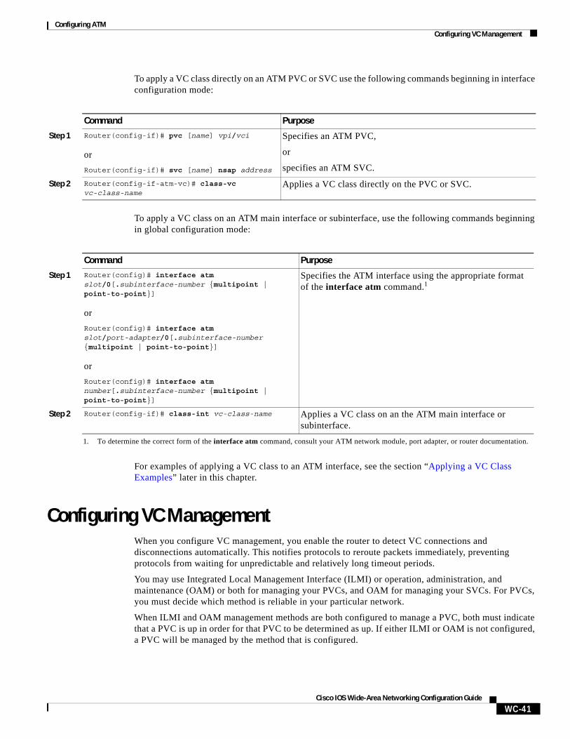
To apply a VC class directly on an ATM PVC or SVC use the following commands beginning in interface configuration mode:
To apply a VC class on an ATM main interface or subinterface, use the following commands beginning in global configuration mode:
For examples of applying a VC class to an ATM interface, see the section “Applying a VC Class Examples” later in this chapter.
Configuring VC ManagementWhen you configure VC management, you enable the router to detect VC connections and disconnections automatically. This notifies protocols to reroute packets immediately, preventing protocols from waiting for unpredictable and relatively long timeout periods.
You may use Integrated Local Management Interface (ILMI) or operation, administration, and maintenance (OAM) or both for managing your PVCs, and OAM for managing your SVCs. For PVCs, you must decide which method is reliable in your particular network.
When ILMI and OAM management methods are both configured to manage a PVC, both must indicate that a PVC is up in order for that PVC to be determined as up. If either ILMI or OAM is not configured, a PVC will be managed by the method that is configured.
Command Purpose
Step 1 Router(config-if)# pvc [name] vpi/vci
or
Router(config-if)# svc [name] nsap address
Specifies an ATM PVC,
or
specifies an ATM SVC.
Step 2 Router(config-if-atm-vc)# class-vc vc-class-name
Applies a VC class directly on the PVC or SVC.
Command Purpose
Step 1 Router(config)# interface atm slot/0[.subinterface-number {multipoint | point-to-point}]
or
Router(config)# interface atm slot/port-adapter/0[.subinterface-number {multipoint | point-to-point}]
or
Router(config)# interface atm number[.subinterface-number {multipoint | point-to-point}]
Specifies the ATM interface using the appropriate format of the interface atm command.1
1. To determine the correct form of the interface atm command, consult your ATM network module, port adapter, or router documentation.
Step 2 Router(config-if)# class-int vc-class-name Applies a VC class on an the ATM main interface or subinterface.
Configuring ATMConfiguring VC Management
WC-42Cisco IOS Wide-Area Networking Configuration Guide
When a PVC goes down, route caches for protocols configured on that PVC are cleared (or flushed) so that new routes may be learned. The route cache flush is applied on the PVC’s interface. When all PVCs on a subinterface go down, VC management shuts down the subinterface in addition to flushing route caches. ATM hardware must keep the PVC active, however, so that OAM and ILMI cells may flow. When any PVC on a subinterface comes up, the subinterface is brought up.
VC management using ILMI is referred to as ILMI management. VC management using OAM is referred to as OAM management. To configure either management method or both, perform the tasks in one or both of the following sections:
• Configuring ILMI Management
• Configuring OAM Management
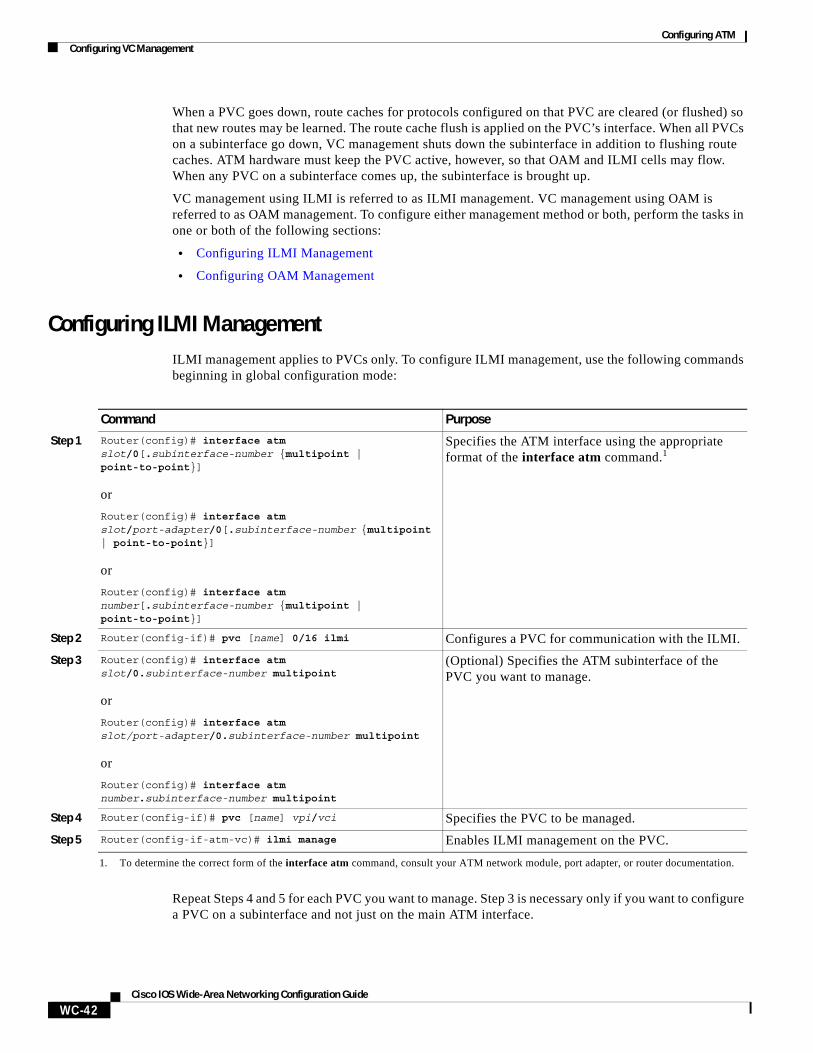
Configuring ILMI ManagementILMI management applies to PVCs only. To configure ILMI management, use the following commands beginning in global configuration mode:
Repeat Steps 4 and 5 for each PVC you want to manage. Step 3 is necessary only if you want to configure a PVC on a subinterface and not just on the main ATM interface.
Command Purpose
Step 1 Router(config)# interface atm slot/0[.subinterface-number {multipoint | point-to-point}]
or
Router(config)# interface atm slot/port-adapter/0[.subinterface-number {multipoint | point-to-point}]
or
Router(config)# interface atm number[.subinterface-number {multipoint | point-to-point}]
Specifies the ATM interface using the appropriate format of the interface atm command.1
1. To determine the correct form of the interface atm command, consult your ATM network module, port adapter, or router documentation.
Step 2 Router(config-if)# pvc [name] 0/16 ilmi Configures a PVC for communication with the ILMI.
Step 3 Router(config)# interface atm slot/0.subinterface-number multipoint
or
Router(config)# interface atm slot/port-adapter/0.subinterface-number multipoint
or
Router(config)# interface atm number.subinterface-number multipoint
(Optional) Specifies the ATM subinterface of the PVC you want to manage.
Step 4 Router(config-if)# pvc [name] vpi/vci Specifies the PVC to be managed.
Step 5 Router(config-if-atm-vc)# ilmi manage Enables ILMI management on the PVC.
Configuring ATMConfiguring VC Management
WC-43Cisco IOS Wide-Area Networking Configuration Guide
The PVC comes up only if ILMI indicates the PVC is up. The PVC comes down when ILMI indicates that the PVC is down. If OAM management is also configured for the same PVC, the PVC comes up only if both ILMI and OAM indicate that the PVC is up.
For an example of configuring ILMI management on a PVC, see the section “ILMI Management on an ATM PVC Example” at the end of this chapter.
Configuring OAM ManagementOAM management may be enabled for both PVCs and SVCs. To configure OAM management, perform the tasks in one or both of the following sections:
• Configuring OAM Management for PVCs
• Configuring OAM Management for SVCs
Configuring OAM Management for PVCs
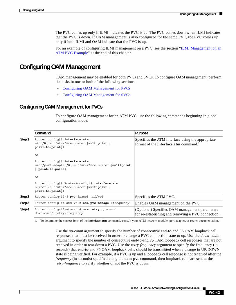
To configure OAM management for an ATM PVC, use the following commands beginning in global configuration mode:
Use the up-count argument to specify the number of consecutive end-to-end F5 OAM loopback cell responses that must be received in order to change a PVC connection state to up. Use the down-count argument to specify the number of consecutive end-to-end F5 OAM loopback cell responses that are not received in order to tear down a PVC. Use the retry-frequency argument to specify the frequency (in seconds) that end-to-end F5 OAM loopback cells should be transmitted when a change in UP/DOWN state is being verified. For example, if a PVC is up and a loopback cell response is not received after the frequency (in seconds) specified using the oam-pvc command, then loopback cells are sent at the retry-frequency to verify whether or not the PVC is down.
Command Purpose
Step 1 Router(config)# interface atm slot/0[.subinterface-number {multipoint | point-to-point}]
or
Router(config)# interface atm slot/port-adapter/0[.subinterface-number {multipoint | point-to-point}]
or
Router(config)# Router(config)# interface atm number[.subinterface-number {multipoint | point-to-point}]
Specifies the ATM interface using the appropriate format of the interface atm command.1
1. To determine the correct form of the interface atm command, consult your ATM network module, port adapter, or router documentation.
Step 2 Router(config-if)# pvc [name] vpi/vci Specifies the ATM PVC.
Step 3 Router(config-if-atm-vc)# oam-pvc manage [frequency] Enables OAM management on the PVC.
Step 4 Router(config-if-atm-vc)# oam retry up-count down-count retry-frequency
(Optional) Specifies OAM management parameters for re-establishing and removing a PVC connection.
Configuring ATMConfiguring VC Management
WC-44Cisco IOS Wide-Area Networking Configuration Guide
By default, end-to-end F5 OAM loopback cell generation is turned off for each PVC. A PVC is determined as down when any of the following is true on that PVC:
• The router does not receive a loopback reply after a configured number of retries of sending end-to-end F5 OAM loopback cells.
• The router receives a Virtual Circuit-Alarm Indication Signals (VC-AIS) cell.
• The router receives a Virtual Circuit-Remote Detect Indicator (VC-RDI) cell.
A PVC is determined as up when all of the following are true on that PVC:
• The router receives a configured number of successive end-to-end F5 OAM loopback cell replies.
• The router does not receive VC-AIS cell for 3 seconds.
• The router does not receive VC-RDI cell for 3 seconds.
For an example of configuring OAM management on a PVC, see the section “OAM Management on an ATM SVC Example” at the end of this chapter.
Configuring OAM Management for SVCs
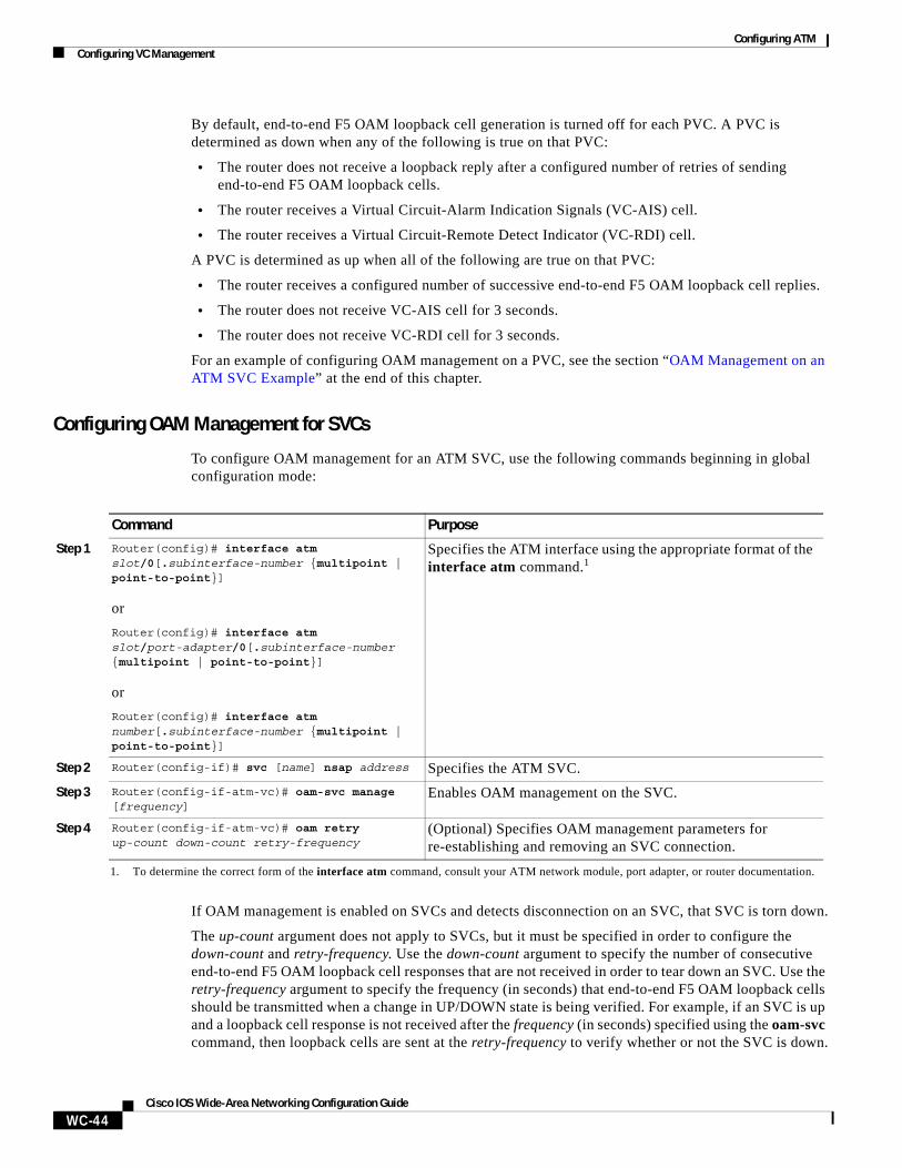
To configure OAM management for an ATM SVC, use the following commands beginning in global configuration mode:
If OAM management is enabled on SVCs and detects disconnection on an SVC, that SVC is torn down.
The up-count argument does not apply to SVCs, but it must be specified in order to configure the down-count and retry-frequency. Use the down-count argument to specify the number of consecutive end-to-end F5 OAM loopback cell responses that are not received in order to tear down an SVC. Use the retry-frequency argument to specify the frequency (in seconds) that end-to-end F5 OAM loopback cells should be transmitted when a change in UP/DOWN state is being verified. For example, if an SVC is up and a loopback cell response is not received after the frequency (in seconds) specified using the oam-svc command, then loopback cells are sent at the retry-frequency to verify whether or not the SVC is down.
Command Purpose
Step 1 Router(config)# interface atm slot/0[.subinterface-number {multipoint | point-to-point}]
or
Router(config)# interface atm slot/port-adapter/0[.subinterface-number {multipoint | point-to-point}]
or
Router(config)# interface atm number[.subinterface-number {multipoint | point-to-point}]
Specifies the ATM interface using the appropriate format of the interface atm command.1
1. To determine the correct form of the interface atm command, consult your ATM network module, port adapter, or router documentation.
Step 2 Router(config-if)# svc [name] nsap address Specifies the ATM SVC.
Step 3 Router(config-if-atm-vc)# oam-svc manage [frequency]
Enables OAM management on the SVC.
Step 4 Router(config-if-atm-vc)# oam retry up-count down-count retry-frequency
(Optional) Specifies OAM management parameters for re-establishing and removing an SVC connection.
Configuring ATMConfiguring Classical IP and ARP over ATM
WC-45Cisco IOS Wide-Area Networking Configuration Guide
For an example of configuring OAM management on an SVC, see the section “OAM Management on an ATM SVC Example” at the end of this chapter.
Configuring Classical IP and ARP over ATMCisco implements both the ATM Address Resolution Protocol (ARP) server and ATM ARP client functions described in RFC 1577. RFC 1577 models an ATM network as a logical IP subnetwork on a LAN.
The tasks required to configure classical IP and ARP over ATM depend on whether the environment uses SVCs or PVCs.
Configuring Classical IP and ARP in an SVC EnvironmentThe ATM ARP mechanism is applicable to networks that use SVCs. It requires a network administrator to configure only the device’s own ATM address and that of a single ATM ARP server into each client device. When the client makes a connection to the ATM ARP server, the server sends ATM Inverse ARP requests to learn the IP network address and ATM address of the client on the network. It uses the addresses to resolve future ATM ARP requests from clients. Static configuration of the server is not required or needed.
In Cisco’s implementation, the ATM ARP client tries to maintain a connection to the ATM ARP server. The ATM ARP server can tear down the connection, but the client attempts once each minute to bring the connection back up. No error messages are generated for a failed connection, but the client will not route packets until the ATM ARP server is connected and translates IP network addresses.
For each packet with an unknown IP address, the client sends an ATM ARP request to the server. Until that address is resolved, any IP packet routed to the ATM interface will cause the client to send another ATM ARP request. When the ARP server responds, the client opens a connection to the new destination so that any additional packets can be routed to it.
Cisco routers may be configured as ATM ARP clients to work with any ATM ARP server conforming to RFC 1577. Alternatively, one of the Cisco routers in a logical IP subnet (LIS) may be configured to act as the ATM ARP server itself. In this case, it automatically acts as a client as well. To configure classical IP and ARP in an SVC environment, perform the tasks in one of the following sections:
• Configuring the Router as an ATM ARP Client
• Configuring the Router as an ATM ARP Server
Configuring ATMConfiguring Classical IP and ARP over ATM
WC-46Cisco IOS Wide-Area Networking Configuration Guide
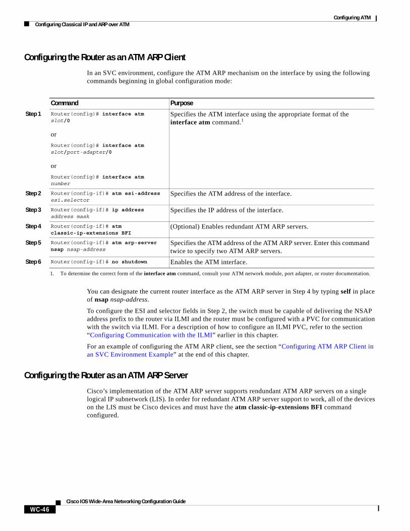
Configuring the Router as an ATM ARP Client
In an SVC environment, configure the ATM ARP mechanism on the interface by using the following commands beginning in global configuration mode:
You can designate the current router interface as the ATM ARP server in Step 4 by typing self in place of nsap nsap-address.
To configure the ESI and selector fields in Step 2, the switch must be capable of delivering the NSAP address prefix to the router via ILMI and the router must be configured with a PVC for communication with the switch via ILMI. For a description of how to configure an ILMI PVC, refer to the section “Configuring Communication with the ILMI” earlier in this chapter.
For an example of configuring the ATM ARP client, see the section “Configuring ATM ARP Client in an SVC Environment Example” at the end of this chapter.
Configuring the Router as an ATM ARP Server
Cisco’s implementation of the ATM ARP server supports rendundant ATM ARP servers on a single logical IP subnetwork (LIS). In order for redundant ATM ARP server support to work, all of the devices on the LIS must be Cisco devices and must have the atm classic-ip-extensions BFI command configured.
Command Purpose
Step 1 Router(config)# interface atm slot/0
or
Router(config)# interface atm slot/port-adapter/0
or
Router(config)# interface atm number
Specifies the ATM interface using the appropriate format of the interface atm command.1
1. To determine the correct form of the interface atm command, consult your ATM network module, port adapter, or router documentation.
Step 2 Router(config-if)# atm esi-address esi.selector
Specifies the ATM address of the interface.
Step 3 Router(config-if)# ip address address mask
Specifies the IP address of the interface.
Step 4 Router(config-if)# atm classic-ip-extensions BFI
(Optional) Enables redundant ATM ARP servers.
Step 5 Router(config-if)# atm arp-server nsap nsap-address
Specifies the ATM address of the ATM ARP server. Enter this command twice to specify two ATM ARP servers.
Step 6 Router(config-if)# no shutdown Enables the ATM interface.
Configuring ATMConfiguring Classical IP and ARP over ATM
WC-47Cisco IOS Wide-Area Networking Configuration Guide
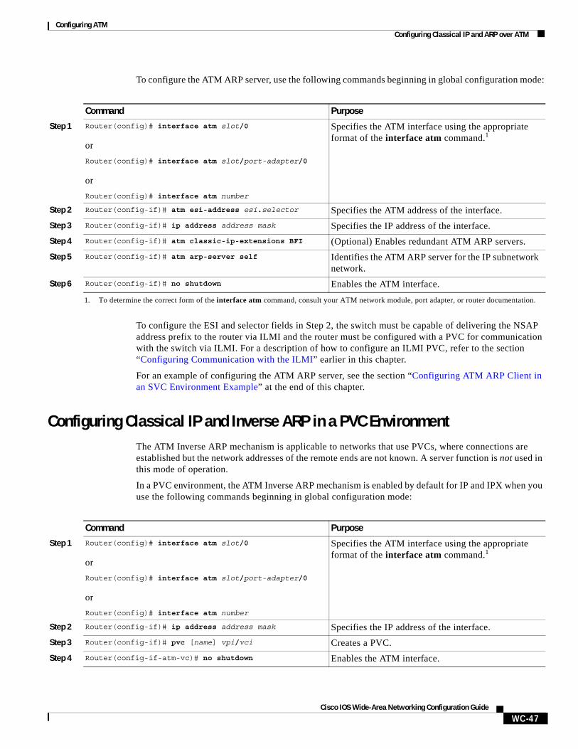
To configure the ATM ARP server, use the following commands beginning in global configuration mode:
To configure the ESI and selector fields in Step 2, the switch must be capable of delivering the NSAP address prefix to the router via ILMI and the router must be configured with a PVC for communication with the switch via ILMI. For a description of how to configure an ILMI PVC, refer to the section “Configuring Communication with the ILMI” earlier in this chapter.
For an example of configuring the ATM ARP server, see the section “Configuring ATM ARP Client in an SVC Environment Example” at the end of this chapter.
Configuring Classical IP and Inverse ARP in a PVC EnvironmentThe ATM Inverse ARP mechanism is applicable to networks that use PVCs, where connections are established but the network addresses of the remote ends are not known. A server function is not used in this mode of operation.
In a PVC environment, the ATM Inverse ARP mechanism is enabled by default for IP and IPX when you use the following commands beginning in global configuration mode:
Command Purpose
Step 1 Router(config)# interface atm slot/0
or
Router(config)# interface atm slot/port-adapter/0
or
Router(config)# interface atm number
Specifies the ATM interface using the appropriate format of the interface atm command.1
1. To determine the correct form of the interface atm command, consult your ATM network module, port adapter, or router documentation.
Step 2 Router(config-if)# atm esi-address esi.selector Specifies the ATM address of the interface.
Step 3 Router(config-if)# ip address address mask Specifies the IP address of the interface.
Step 4 Router(config-if)# atm classic-ip-extensions BFI (Optional) Enables redundant ATM ARP servers.
Step 5 Router(config-if)# atm arp-server self Identifies the ATM ARP server for the IP subnetwork network.
Step 6 Router(config-if)# no shutdown Enables the ATM interface.
Command Purpose
Step 1 Router(config)# interface atm slot/0
or
Router(config)# interface atm slot/port-adapter/0
or
Router(config)# interface atm number
Specifies the ATM interface using the appropriate format of the interface atm command.1
Step 2 Router(config-if)# ip address address mask Specifies the IP address of the interface.
Step 3 Router(config-if)# pvc [name] vpi/vci Creates a PVC.
Step 4 Router(config-if-atm-vc)# no shutdown Enables the ATM interface.
Configuring ATMCustomizing the ATM Interface
WC-48Cisco IOS Wide-Area Networking Configuration Guide
Repeat Step 3 for each PVC you want to create.
By default, Inverse ARP datagrams will be sent on this virtual circuit every 15 minutes. To adjust the Inverse ARP time period, use the inarp minutes command in interface-ATM-VC configuration mode.
Note The ATM ARP mechanism works with IP only. The Inverse ATM ARP mechanism works with IP and IPX only. For all other protocols, the destination address must be specified.
For an example of configuring the ATM Inverse ARP mechanism, see the section “Configuring ATM Inverse ARP in a PVC Environment Example” at the end of this chapter.
Customizing the ATM InterfaceYou can customize the ATM interface. The features you can customize have default values that will most likely suit your environment and probably need not be changed. However, you might need to enter configuration commands, depending upon the requirements for your system configuration and the protocols you plan to route on the interface. To customize the ATM interface, perform the tasks in the following sections:
• Configuring the Rate Queue
• Configuring MTU Size
• Setting the SONET PLIM
• Setting Loopback Mode
• Setting the Exception Queue Length
• Configuring the Maximum Number of Channels
• Limiting the Number of Virtual Circuits
• Setting the Raw-Queue Size
• Configuring Buffer Size
• Setting the VCI-to-VPI Ratio
• Setting the Source of the Transmit Clock
Configuring the Rate QueueA rate queue defines the speed at which individual virtual circuits will transmit data to the remote end. You can configure permanent rate queues, allow the software to set up dynamic rate queues, or perform some combination of the two. The software dynamically creates rate queues when you create a VC with a peak rate that does not match any user-configured rate queue. The software dynamically creates all rate queues if you have not configured any.
Note You can only configure the rate queue for the AIP and NPM.
1. To determine the correct form of the interface atm command, consult your ATM network module, port adapter, or router documentation.
Configuring ATMCustomizing the ATM Interface
WC-49Cisco IOS Wide-Area Networking Configuration Guide
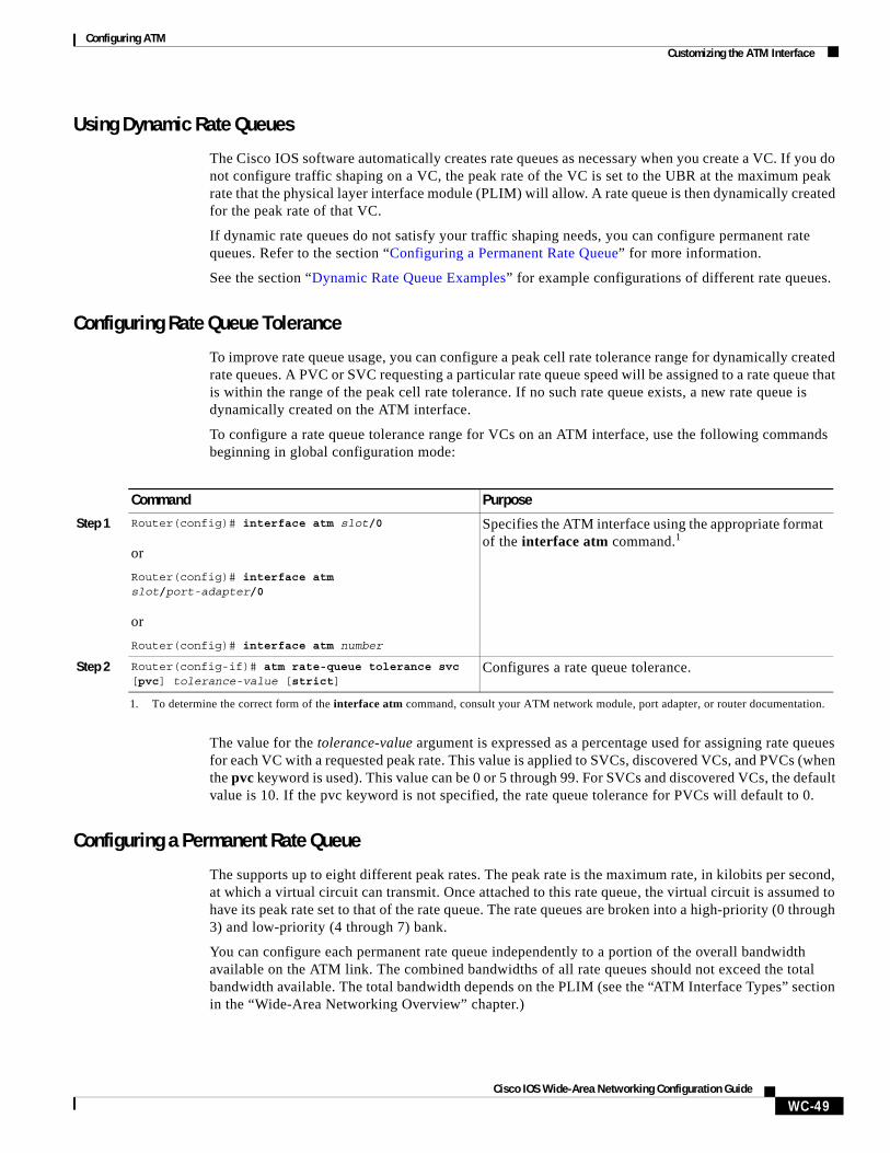
Using Dynamic Rate Queues
The Cisco IOS software automatically creates rate queues as necessary when you create a VC. If you do not configure traffic shaping on a VC, the peak rate of the VC is set to the UBR at the maximum peak rate that the physical layer interface module (PLIM) will allow. A rate queue is then dynamically created for the peak rate of that VC.
If dynamic rate queues do not satisfy your traffic shaping needs, you can configure permanent rate queues. Refer to the section “Configuring a Permanent Rate Queue” for more information.
See the section “Dynamic Rate Queue Examples” for example configurations of different rate queues.
Configuring Rate Queue Tolerance
To improve rate queue usage, you can configure a peak cell rate tolerance range for dynamically created rate queues. A PVC or SVC requesting a particular rate queue speed will be assigned to a rate queue that is within the range of the peak cell rate tolerance. If no such rate queue exists, a new rate queue is dynamically created on the ATM interface.
To configure a rate queue tolerance range for VCs on an ATM interface, use the following commands beginning in global configuration mode:
The value for the tolerance-value argument is expressed as a percentage used for assigning rate queues for each VC with a requested peak rate. This value is applied to SVCs, discovered VCs, and PVCs (when the pvc keyword is used). This value can be 0 or 5 through 99. For SVCs and discovered VCs, the default value is 10. If the pvc keyword is not specified, the rate queue tolerance for PVCs will default to 0.
Configuring a Permanent Rate Queue
The supports up to eight different peak rates. The peak rate is the maximum rate, in kilobits per second, at which a virtual circuit can transmit. Once attached to this rate queue, the virtual circuit is assumed to have its peak rate set to that of the rate queue. The rate queues are broken into a high-priority (0 through 3) and low-priority (4 through 7) bank.
You can configure each permanent rate queue independently to a portion of the overall bandwidth available on the ATM link. The combined bandwidths of all rate queues should not exceed the total bandwidth available. The total bandwidth depends on the PLIM (see the “ATM Interface Types” section in the “Wide-Area Networking Overview” chapter.)
Command Purpose
Step 1 Router(config)# interface atm slot/0
or
Router(config)# interface atm slot/port-adapter/0
or
Router(config)# interface atm number
Specifies the ATM interface using the appropriate format of the interface atm command.1
1. To determine the correct form of the interface atm command, consult your ATM network module, port adapter, or router documentation.
Step 2 Router(config-if)# atm rate-queue tolerance svc [pvc] tolerance-value [strict]
Configures a rate queue tolerance.
Configuring ATMCustomizing the ATM Interface
WC-50Cisco IOS Wide-Area Networking Configuration Guide
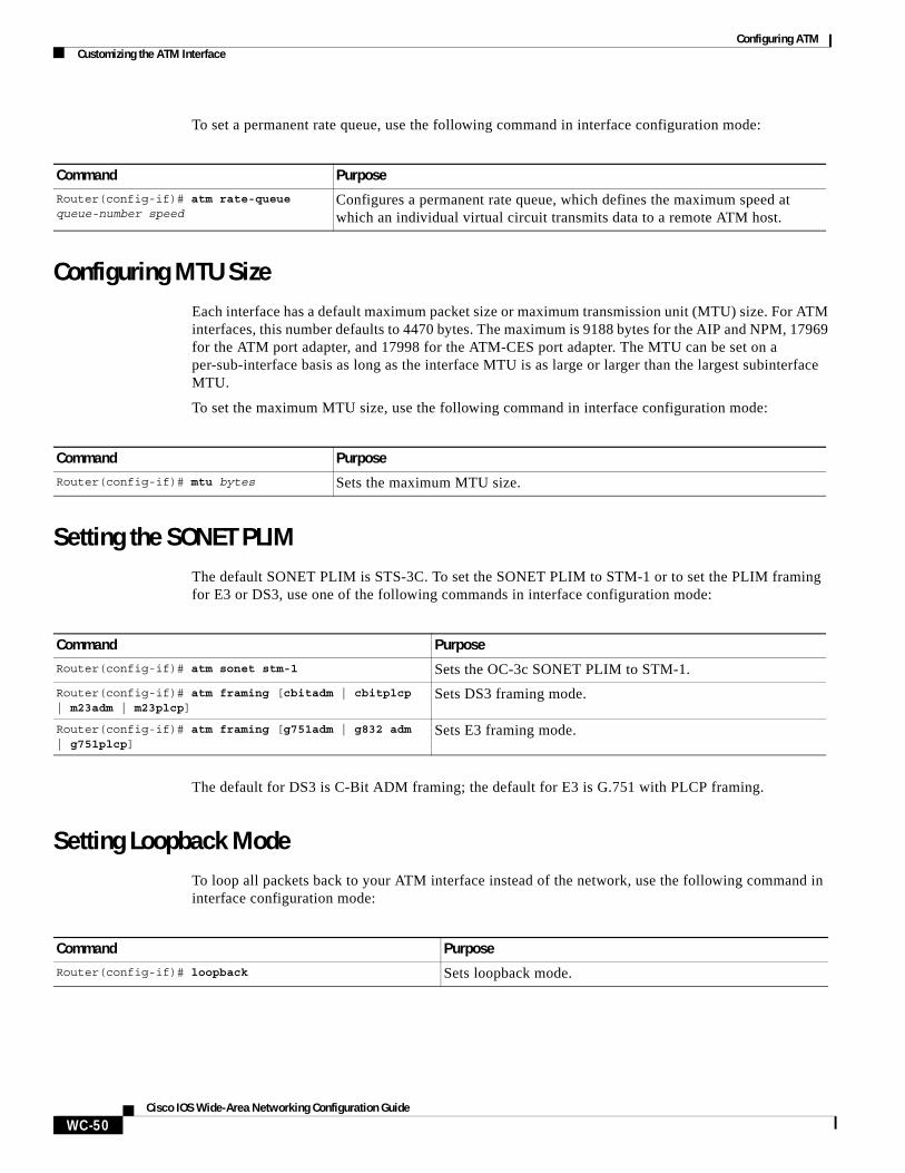
To set a permanent rate queue, use the following command in interface configuration mode:
Configuring MTU SizeEach interface has a default maximum packet size or maximum transmission unit (MTU) size. For ATM interfaces, this number defaults to 4470 bytes. The maximum is 9188 bytes for the AIP and NPM, 17969 for the ATM port adapter, and 17998 for the ATM-CES port adapter. The MTU can be set on a per-sub-interface basis as long as the interface MTU is as large or larger than the largest subinterface MTU.
To set the maximum MTU size, use the following command in interface configuration mode:
Setting the SONET PLIMThe default SONET PLIM is STS-3C. To set the SONET PLIM to STM-1 or to set the PLIM framing for E3 or DS3, use one of the following commands in interface configuration mode:
The default for DS3 is C-Bit ADM framing; the default for E3 is G.751 with PLCP framing.
Setting Loopback ModeTo loop all packets back to your ATM interface instead of the network, use the following command in interface configuration mode:
Command PurposeRouter(config-if)# atm rate-queue queue-number speed
Configures a permanent rate queue, which defines the maximum speed at which an individual virtual circuit transmits data to a remote ATM host.
Command Purpose
Router(config-if)# mtu bytes Sets the maximum MTU size.
Command Purpose
Router(config-if)# atm sonet stm-1 Sets the OC-3c SONET PLIM to STM-1.
Router(config-if)# atm framing [cbitadm | cbitplcp | m23adm | m23plcp]
Sets DS3 framing mode.
Router(config-if)# atm framing [g751adm | g832 adm | g751plcp]
Sets E3 framing mode.
Command Purpose
Router(config-if)# loopback Sets loopback mode.
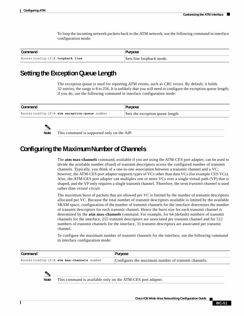
Configuring ATMCustomizing the ATM Interface
WC-51Cisco IOS Wide-Area Networking Configuration Guide
To loop the incoming network packets back to the ATM network, use the following command in interface configuration mode:
Setting the Exception Queue LengthThe exception queue is used for reporting ATM events, such as CRC errors. By default, it holds 32 entries; the range is 8 to 256. It is unlikely that you will need to configure the exception queue length; if you do, use the following command in interface configuration mode:
Note This command is supported only on the AIP.
Configuring the Maximum Number of ChannelsThe atm max-channels command, available if you are using the ATM-CES port adapter, can be used to divide the available number (fixed) of transmit descriptors across the configured number of transmit channels. Typically, you think of a one-to-one association between a transmit channel and a VC; however, the ATM-CES port adapter supports types of VCs other than data VCs (for example CES VCs). Also, the ATM-CES port adapter can multiplex one or more VCs over a single virtual path (VP) that is shaped, and the VP only requires a single transmit channel. Therefore, the term transmit channel is used rather than virtual circuit.
The maximum burst of packets that are allowed per VC is limited by the number of transmit descriptors allocated per VC. Because the total number of transmit descriptors available is limited by the available SRAM space, configuration of the number of transmit channels for the interface determines the number of transmit descriptors for each transmit channel. Hence the burst size for each transmit channel is determined by the atm max-channels command. For example, for 64 (default) numbers of transmit channels for the interface, 255 transmit descriptors are associated per transmit channel and for 512 numbers of transmit channels for the interface, 31 transmit descriptors are associated per transmit channel.
To configure the maximum number of transmit channels for the interface, use the following command in interface configuration mode:
Note This command is available only on the ATM-CES port adapter.
Command PurposeRouter(config-if)# loopback line Sets line loopback mode.
Command PurposeRouter(config-if)# atm exception-queue number Sets the exception queue length.
Command Purpose
Router(config-if)# atm max-channels number Configures the maximum number of transmit channels.
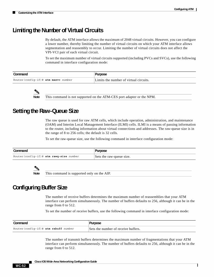
Configuring ATMCustomizing the ATM Interface
WC-52Cisco IOS Wide-Area Networking Configuration Guide
Limiting the Number of Virtual CircuitsBy default, the ATM interface allows the maximum of 2048 virtual circuits. However, you can configure a lower number, thereby limiting the number of virtual circuits on which your ATM interface allows segmentation and reassembly to occur. Limiting the number of virtual circuits does not affect the VPI-VCI pair of each virtual circuit.
To set the maximum number of virtual circuits supported (including PVCs and SVCs), use the following command in interface configuration mode:
Note This command is not supported on the ATM-CES port adapter or the NPM.
Setting the Raw-Queue SizeThe raw queue is used for raw ATM cells, which include operation, administration, and maintenance (OAM) and Interim Local Management Interface (ILMI) cells. ILMI is a means of passing information to the router, including information about virtual connections and addresses. The raw-queue size is in the range of 8 to 256 cells; the default is 32 cells.
To set the raw-queue size, use the following command in interface configuration mode:
Note This command is supported only on the AIP.
Configuring Buffer SizeThe number of receive buffers determines the maximum number of reassemblies that your ATM interface can perform simultaneously. The number of buffers defaults to 256, although it can be in the range from 0 to 512.
To set the number of receive buffers, use the following command in interface configuration mode:
The number of transmit buffers determines the maximum number of fragmentations that your ATM interface can perform simultaneously. The number of buffers defaults to 256, although it can be in the range from 0 to 512.
Command Purpose
Router(config-if)# atm maxvc number Limits the number of virtual circuits.
Command Purpose
Router(config-if)# atm rawq-size number Sets the raw-queue size.
Command PurposeRouter(config-if)# atm rxbuff number Sets the number of receive buffers.
Configuring ATMConfiguring ATM Subinterfaces for SMDS Networks
WC-53Cisco IOS Wide-Area Networking Configuration Guide
To set the number of transmit buffers, use the following command in interface configuration mode:
Note The commands in this section are not supported on the ATM-CES port adapter or NPM.
Setting the VCI-to-VPI RatioBy default, the ATM interface supports 1024 VCIs per VPI. Depending on what ATM interface card or port adapter you are using, this value can be any power of 2 in the range of 16 to 8192. (See the atm vc-per-vp command in the Cisco IOS Wide-Area Networking Command Reference for the exact values that apply to your configuration.) This value controls the memory allocation on your ATM interface that deals with the VCI table. It defines only the maximum number of VCIs to support per VPI.
To set the maximum number of VCIs to support per VPI and limit the highest VCI accordingly, use the following command in interface configuration mode:
Setting the Source of the Transmit ClockBy default, your ATM interface expects the ATM switch to provide transmit clocking. To specify that the ATM interface generates the transmit clock internally for SONET and E3 PLIM operation, use the following command in interface configuration mode:
Configuring ATM Subinterfaces for SMDS NetworksAn ATM adaptation layer (AAL) defines the conversion of user information into cells by segmenting upper-layer information into cells at the transmitter and reassembling them at the receiver. AAL1 and AAL2 handle isochronous traffic, such as voice and video, and are not relevant to the router. AAL3/4 and AAL5 support data communications by segmenting and reassembling packets. Beginning in Cisco IOS Release 10.2, we support both AAL3/4 and AAL5.
Our implementation of the AAL3/4 encapsulates each AAL3/4 packet in a Switched Multimegabit Data Service (SMDS) header and trailer. This feature supports both unicast and multicast addressing, and provides subinterfaces for multiple AAL3/4 connections over the same physical interface.
Command PurposeRouter(config-if)# atm txbuff number Sets the number of transmit buffers.
Command PurposeRouter(config-if)# atm vc-per-vp number Sets the number of VCIs per VPI.
Command Purpose
Router(config-if)# atm clock internal Specifies that the generate the transmit clock internally.
Configuring ATMConfiguring ATM Subinterfaces for SMDS Networks
WC-54Cisco IOS Wide-Area Networking Configuration Guide
Note Each subinterface configured to support AAL3/4 is allowed only one SMDS E.164 unicast address and one E.164 multicast address. The multicast address is used for all broadcast operations. In addition, only one virtual circuit is allowed on each subinterface that is being used for AAL3/4 processing, and it must be an AAL3/4 virtual circuit.
Support for AAL3/4 on an ATM interface requires static mapping of all protocols except IP. However, dynamic routing of IP can coexist with static mapping of other protocols on the same ATM interface.
To configure an ATM interface for SMDS networks, use the following commands in interface configuration mode:
Note ATM subinterfaces for SMDS networks are only supported on the AIP and NPM.
The virtual path filter provides a mechanism for specifying which VPIs (or a range of VPIs) will be used for AAL3/4 processing during datagram reassembly. All other VPIs are mapped to AAL5 processing. For more information about the way the atm vp-filter command works and the effect of selecting specific values, refer to the Cisco IOS Wide-Area Networking Command Reference.
After configuring the ATM interface for SMDS networks, configure the interface for standard protocol configurations, as needed. For more information about protocol configuration, refer to the relevant chapters of the Cisco IOS IP Configuration Guide, the Cisco IOS AppleTalk and Novell IPX Configuration Guide, and the Cisco IOS Apollo Domain, Banyan VINES, DECnet, ISO CLNS, and XNS Configuration Guide.
For examples of configuring an ATM interface for AAL3/4 support, see the section “PVC with AAL3/4 and SMDS Encapsulation Examples” at the end of this chapter.
Limiting the Message Identifiers Allowed on Virtual CircuitsMessage identifier (MID) numbers are used by receiving devices to reassemble cells from multiple sources into packets.
To ensure that the message identifiers are unique at the receiving end and, therefore, that messages can be reassembled correctly, you can limit the number of message identifiers allowed on a virtual circuit and assign different ranges of message identifiers to different PVCs.
Command Purpose
Step 1 Router(config-if)# atm aal aal3/4 Enables AAL3/4 support on the affected ATM subinterface.
Step 2 Router(config-if)# atm smds-address address Provides an SMDS E.164 unicast address for the subinterface.
Step 3 Router(config-if)# atm multicast address Provides an SMDS E.164 multicast address.
Step 4 Router(config-if)# atm vp-filter hexvalue Configures a virtual path filter for the affected ATM subinterface.
Step 5 Router(config-if)# pvc [name] vpi/vci smds Creates an AAL3/4 PVC.
Configuring ATMConfiguring Fast-Switched Transparent Bridging for SNAP PVCs
WC-55Cisco IOS Wide-Area Networking Configuration Guide
To limit the number of message identifier numbers allowed on each virtual circuit and to assign different ranges of message identifiers to different PVCs, use the following commands beginning in interface configuration mode:
The maximum number of message identifiers per virtual circuit is set at 16 by default; valid values are 16, 32, 64, 128, 256, 512, or 1024.
The default value for both the midlow and the midhigh arguments is zero.
Setting the Virtual Path Filter RegisterThe virtual path filter allows you to specify which VPI or range of VPIs will be used for AAL3/4 processing. The default value of the’s virtual path filter register is 0x7B. To set the virtual path filter register, use the following command in interface configuration mode:
Configuring Fast-Switched Transparent Bridging for SNAP PVCsThe implementation of transparent bridging over ATM allows the spanning tree for an interface to support virtual circuit descriptors (VCDs) for AAL5-LLC Subnetwork Access Protocol (SNAP) encapsulations.
If the relevant interface or subinterface is explicitly put into a bridge group, as described in the task table below, AAL5-SNAP encapsulated bridge packets on a PVC are fast-switched.
The bridging implementation supports IEEE 802.3 frame formats, IEEE 802.10 frame formats, and Ethernet DIX frames. The router can accept IEEE 802.3 frames with or without frame check sequence (FCS). When the router receives frames with FCS (RFC 1483 bridge frame formats with 0x0001 in the PID field of the SNAP header), it strips off the FCS and forwards the frame as necessary. All IEEE 802.3 frames that originate at or are forwarded by the router are sent as 802.3 bridge frames without FCS (bridge frame formats with 0x0007 in the PID field of the SNAP header).
Note Transparent bridging for the ATM works only on AAL5-LLC/SNAP PVCs (fast-switched). AAL3/4-SMDS, AAL5-MUX, and AAL5-NLPID bridging are not yet supported. Transparent bridging for ATM also does not operate in a switched virtual circuit (SVC) environment.
Command Purpose
Step 1 Router(config-if)# atm mid-per-vc maximum Limits the number of message identifiers allowed per virtual circuit.
Step 2 Router(config-if)# pvc [name] vpi/vci smds Creates an ATM PVC with SMDS encapsulation.
Step 3 Router(config-if-atm-vc)# mid midlow midhigh Limits the range of message identifier values used on the PVC.
Command Purpose
Router(config-if)# atm vp-filter hexvalue Sets the virtual path filter register.
Configuring ATMConfiguring Inverse Multiplexing over ATM
WC-56Cisco IOS Wide-Area Networking Configuration Guide
To configure transparent bridging for LLC/SNAP PVCs, use the following commands beginning in global configuration mode:
No other configuration is required. Spanning tree updates are broadcast to all AAL5-SNAP virtual circuits that exist on the ATM interface. Only the AAL5-SNAP virtual circuits on the specific subinterface receive the updates. The router does not send spanning tree updates to AAL5-MUX and AAL5-NLPID virtual circuits.
For an example of transparent bridging for an AAL5-SNAP PVC, see the section “Transparent Bridging on an AAL5-SNAP PVC Example” at the end of this chapter.
Configuring Inverse Multiplexing over ATMInverse multiplexing provides the capability to transmit and receive a single high-speed data stream over multiple slower-speed physical links. In inverse multiplexing over ATM (IMA), the originating stream of ATM cells is divided so that complete ATM cells are transmitted in round-robin order across the set of ATM links.
IMA is supported on the Multiport T1/E1 ATM Network Module with Inverse Multiplexing over ATM on Cisco 2600 and Cisco 3600 series routers and the Multiport T1/E1 ATM Port Adapter with Inverse Multiplexing over ATM on Cisco 7100, Cisco 7200, and Cisco 7500 series routers. The Multiport T1/E1 ATM IMA network modules and port adapters provide four or eight T1 or E1 ports and allow wide-area networking (WAN) uplinks at speeds ranging from 1.536 Mbps to 12.288 Mbps for T1, and from 1.92 Mbps to 15.36 Mbps for E1. See the section “Bandwidth Considerations” later in this chapter for details.
Command Purpose
Step 1 Router(config)# interface atm slot/0[.subinterface-number {multipoint | point-to-point}
or
Router(config)# interface atm slot/port-adapter/0[.subinterface-number {multipoint | point-to-point}]
or
Router(config)# interface atm number[.subinterface-number {multipoint | point-to-point}]
Specifies the ATM interface using the appropriate format of the interface atm command.1
1. To determine the correct form of the interface atm command, consult your ATM network module, port adapter, or router documentation.
Step 2 Router(config-if)# pvc [name] vpi/vci Creates one or more PVCs using AAL5-SNAP encapsulation. Repeat this command as needed.
Step 3 Router(config)# exit Returns to interface configuration mode.
Step 4 Router(config-if)# bridge-group group Assigns the interface to a bridge group.
Step 5 Router(config-if)# exit Returns to global configuration mode.
Step 6 Router(config)# bridge group protocol dec Defines the type of spanning tree protocol as DEC.
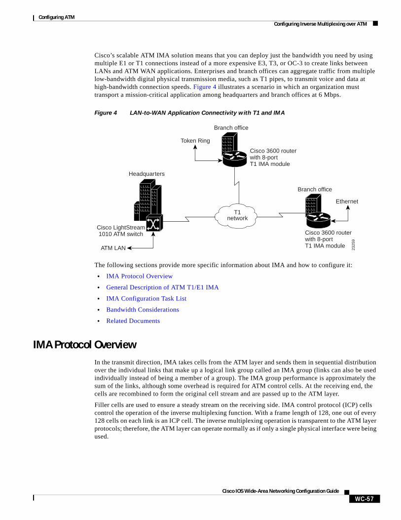
Configuring ATMConfiguring Inverse Multiplexing over ATM
WC-57Cisco IOS Wide-Area Networking Configuration Guide
Cisco’s scalable ATM IMA solution means that you can deploy just the bandwidth you need by using multiple E1 or T1 connections instead of a more expensive E3, T3, or OC-3 to create links between LANs and ATM WAN applications. Enterprises and branch offices can aggregate traffic from multiple low-bandwidth digital physical transmission media, such as T1 pipes, to transmit voice and data at high-bandwidth connection speeds. Figure 4 illustrates a scenario in which an organization must transport a mission-critical application among headquarters and branch offices at 6 Mbps.
Figure 4 LAN-to-WAN Application Connectivity with T1 and IMA
The following sections provide more specific information about IMA and how to configure it:
• IMA Protocol Overview
• General Description of ATM T1/E1 IMA
• IMA Configuration Task List
• Bandwidth Considerations
• Related Documents
IMA Protocol OverviewIn the transmit direction, IMA takes cells from the ATM layer and sends them in sequential distribution over the individual links that make up a logical link group called an IMA group (links can also be used individually instead of being a member of a group). The IMA group performance is approximately the sum of the links, although some overhead is required for ATM control cells. At the receiving end, the cells are recombined to form the original cell stream and are passed up to the ATM layer.
Filler cells are used to ensure a steady stream on the receiving side. IMA control protocol (ICP) cells control the operation of the inverse multiplexing function. With a frame length of 128, one out of every 128 cells on each link is an ICP cell. The inverse multiplexing operation is transparent to the ATM layer protocols; therefore, the ATM layer can operate normally as if only a single physical interface were being used.
2325
9
ATM LAN
Cisco LightStream1010 ATM switch
Headquarters
Branch office
Branch office
Token Ring
T1network
Cisco 3600 router with 8-port T1 IMA module
Cisco 3600 router with 8-port T1 IMA module
Ethernet
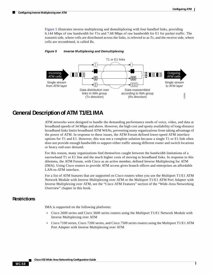
Configuring ATMConfiguring Inverse Multiplexing over ATM
WC-58Cisco IOS Wide-Area Networking Configuration Guide
Figure 5 illustrates inverse multiplexing and demultiplexing with four bundled links, providing 6.144 Mbps of raw bandwidth for T1s and 7.68 Mbps of raw bandwidth for E1 for packet traffic. The transmit side, where cells are distributed across the links, is referred to as Tx, and the receive side, where cells are recombined, is called Rx.
Figure 5 Inverse Multiplexing and Demultiplexing
General Description of ATM T1/E1 IMAATM networks were designed to handle the demanding performance needs of voice, video, and data at broadband speeds of 34 Mbps and above. However, the high cost and spotty availability of long-distance broadband links limits broadband ATM WANs, preventing many organizations from taking advantage of the power of ATM. In response to these issues, the ATM Forum defined lower-speed ATM interface options for T1 and E1. However, this was not a complete solution because a single T1 or E1 link often does not provide enough bandwidth to support either traffic among different router and switch locations or heavy end-user demand.
For this reason, many organizations find themselves caught between the bandwidth limitations of a narrowband T1 or E1 line and the much higher costs of moving to broadband links. In response to this dilemma, the ATM Forum, with Cisco as an active member, defined Inverse Multiplexing for ATM (IMA). Using Cisco routers to provide ATM access gives branch offices and enterprises an affordable LAN-to-ATM interface.
For a list of ATM features that are supported on Cisco routers when you use the Multiport T1/E1 ATM Network Module with Inverse Multiplexing over ATM or the Multiport T1/E1 ATM Port Adapter with Inverse Multiplexing over ATM, see the “Cisco ATM Features” section of the “Wide-Area Networking Overview” chapter in this book.
Restrictions
IMA is supported on the following platforms:
• Cisco 2600 series and Cisco 3600 series routers using the Multiport T1/E1 Network Module with Inverse Multiplexing over ATM
• Cisco 7100 series, Cisco 7200 series, and Cisco 7500 series routers using the Multiport T1/E1 ATM Port Adapter with Inverse Multiplexing over ATM
2326
0
Single streamfrom ATM layer
Data distribution overlinks in IMA group
(Tx direction)
Data reassembledaccording to IMA group
(Rx direction)
T1 or E1 links
Single streamto ATM layer
IncomingATM cells
OutgoingATM cells
Configuring ATMConfiguring Inverse Multiplexing over ATM
WC-59Cisco IOS Wide-Area Networking Configuration Guide
The following restrictions apply to the ATM IMA feature on Cisco 7100 series, Cisco 7200 series, and Cisco 7500 series routers:
• If common transmit clock is configured on an IMA interface using the ima clock-mode command wtih the common keyword, then the port adapter internal clock is used as the transmit clock source for all the links of the IMA interface.
• The feature does not support the ATM real-time variable bit rate (rt-VBR) traffic category. The ATM constant bit rate (CBR) traffic category can be approximated by configuring a non-real-time variable bit rate (nrt-VBR) VC with the same parameters for the sustainable cell rate (SCR) and peak cell rate (PCR).
• The following restrictions apply to SNMP:
– IMA failure alarm trap is not supported.
– Set operation for IMA MIB is not supported.
• The IP ATM_COS feature is not supported on Cisco 7500 series routers.
IMA Configuration Task ListThe following sections describe the configuration and verification tasks required to set up ATM IMA groups. You can also configure ATM links individually, but these sections include only the steps for configuring IMA groups. To configure and verify IMA groups on an ATM interface, complete the tasks in the following sections. Each task is identified as optional or required.
• Configuring an ATM Interface for IMA Operation (Required)
• Verifying an ATM Interface Configured for IMA Operation (Optional)
• Configuring IMA Groups (Required)
• Verifying IMA Group Configuration (Optional)
• Troubleshooting Tips (Optional)
For examples of IMA configuration, see the section “Inverse Multiplexing over ATM Examples” at the end of this chapter.
Configuring an ATM Interface for IMA Operation
To configure the ATM interface for IMA operation, perform the tasks in one of the following two sections:
• Configuring the ATM Interface on the Multiport T1/E1 ATM Network Module for IMA Operation
• Configuring the ATM Interface on the Multiport T1/E1 ATM Port Adapter for IMA Operation
Configuring the ATM Interface on the Multiport T1/E1 ATM Network Module for IMA Operation
To configure an ATM interface on a Multiport T1/E1 ATM Network Module with Inverse Multiplexing over ATM for IMA operation, use the following commands beginning in global configuration mode:
Command Purpose
Step 1 Router(config)# interface atm slot/port Enters interface configuration mode and specifies the location of the interface.
Step 2 Router(config-if)# clock source {line | internal | {loop-timed}
Sets the clock source for a link.
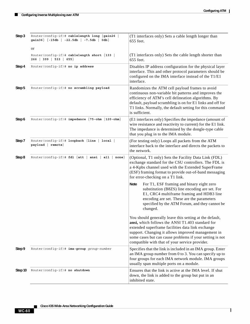
Configuring ATMConfiguring Inverse Multiplexing over ATM
WC-60Cisco IOS Wide-Area Networking Configuration Guide
Step 3 Router(config-if)# cablelength long {gain26 | gain36} {-15db | -22.5db | -7.5db | 0db}
or
Router(config-if)# cablelength short {133 | 266 | 399 | 533 | 655}
(T1 interfaces only) Sets a cable length longer than 655 feet.
(T1 interfaces only) Sets the cable length shorter than 655 feet.
Step 4 Router(config-if)# no ip address Disables IP address configuration for the physical layer interface. This and other protocol parameters should be configured on the IMA interface instead of the T1/E1 interface.
Step 5 Router(config-if)# no scrambling payload Randomizes the ATM cell payload frames to avoid continuous non-variable bit patterns and improves the efficiency of ATM’s cell delineation algorithms. By default, payload scrambling is on for E1 links and off for T1 links. Normally, the default setting for this command is sufficient.
Step 6 Router(config-if)# impedance {75-ohm |120-ohm} (E1 interfaces only) Specifies the impedance (amount of wire resistance and reactivity to current) for the E1 link. The impedance is determined by the dongle-type cable that you plug in to the IMA module.
Step 7 Router(config-if)# loopback [line | local | payload | remote]
(For testing only) Loops all packets from the ATM interface back to the interface and directs the packets to the network.
Step 8 Router(config-if)# fdl {att | ansi | all | none} (Optional, T1 only) Sets the Facility Data Link (FDL) exchange standard for the CSU controllers. The FDL is a 4-Kpbs channel used with the Extended SuperFrame (ESF) framing format to provide out-of-band messaging for error-checking on a T1 link.
Note For T1, ESF framing and binary eight zero substitution (B8ZS) line encoding are set. For E1, CRC4 multiframe framing and HDB3 line encoding are set. These are the parameters specified by the ATM Forum, and they cannot be changed.
You should generally leave this setting at the default, ansi, which follows the ANSI T1.403 standard for extended superframe facilities data link exchange support. Changing it allows improved management in some cases but can cause problems if your setting is not compatible with that of your service provider.
Step 9 Router(config-if)# ima-group group-number Specifies that the link is included in an IMA group. Enter an IMA group number from 0 to 3. You can specify up to four groups for each IMA network module. IMA groups usually span multiple ports on a module.
Step 10 Router(config-if)# no shutdown Ensures that the link is active at the IMA level. If shut down, the link is added to the group but put in an inhibited state.
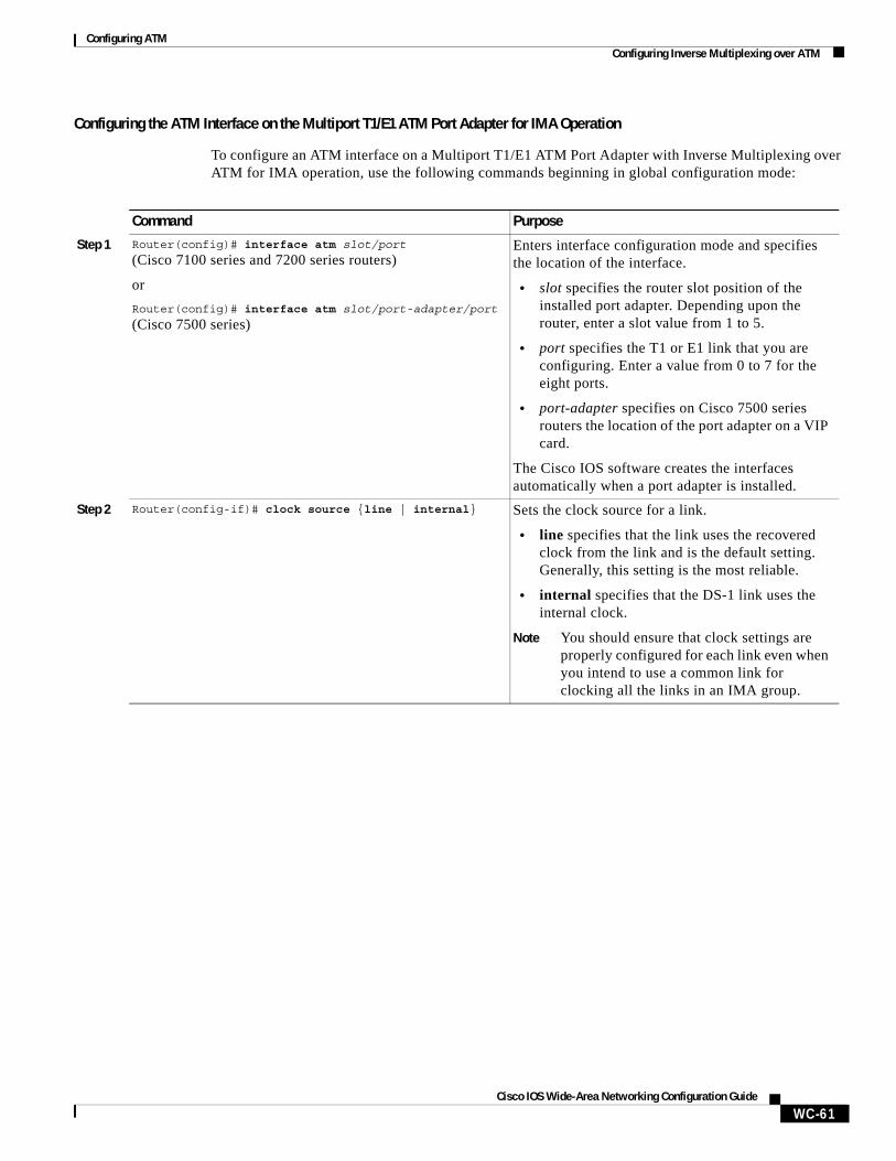
Configuring ATMConfiguring Inverse Multiplexing over ATM
WC-61Cisco IOS Wide-Area Networking Configuration Guide
Configuring the ATM Interface on the Multiport T1/E1 ATM Port Adapter for IMA Operation
To configure an ATM interface on a Multiport T1/E1 ATM Port Adapter with Inverse Multiplexing over ATM for IMA operation, use the following commands beginning in global configuration mode:
Command Purpose
Step 1 Router(config)# interface atm slot/port
(Cisco 7100 series and 7200 series routers)
or
Router(config)# interface atm slot/port-adapter/port
(Cisco 7500 series)
Enters interface configuration mode and specifies the location of the interface.
• slot specifies the router slot position of the installed port adapter. Depending upon the router, enter a slot value from 1 to 5.
• port specifies the T1 or E1 link that you are configuring. Enter a value from 0 to 7 for the eight ports.
• port-adapter specifies on Cisco 7500 series routers the location of the port adapter on a VIP card.
The Cisco IOS software creates the interfaces automatically when a port adapter is installed.
Step 2 Router(config-if)# clock source {line | internal} Sets the clock source for a link.
• line specifies that the link uses the recovered clock from the link and is the default setting. Generally, this setting is the most reliable.
• internal specifies that the DS-1 link uses the internal clock.
Note You should ensure that clock settings are properly configured for each link even when you intend to use a common link for clocking all the links in an IMA group.
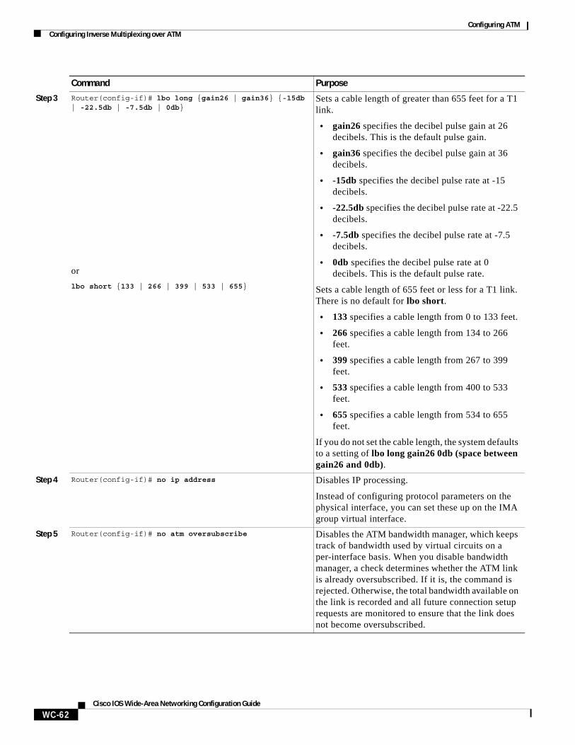
Configuring ATMConfiguring Inverse Multiplexing over ATM
WC-62Cisco IOS Wide-Area Networking Configuration Guide
Step 3 Router(config-if)# lbo long {gain26 | gain36} {-15db | -22.5db | -7.5db | 0db}
or
lbo short {133 | 266 | 399 | 533 | 655}
Sets a cable length of greater than 655 feet for a T1 link.
• gain26 specifies the decibel pulse gain at 26 decibels. This is the default pulse gain.
• gain36 specifies the decibel pulse gain at 36 decibels.
• -15db specifies the decibel pulse rate at -15 decibels.
• -22.5db specifies the decibel pulse rate at -22.5 decibels.
• -7.5db specifies the decibel pulse rate at -7.5 decibels.
• 0db specifies the decibel pulse rate at 0 decibels. This is the default pulse rate.
Sets a cable length of 655 feet or less for a T1 link. There is no default for lbo short.
• 133 specifies a cable length from 0 to 133 feet.
• 266 specifies a cable length from 134 to 266 feet.
• 399 specifies a cable length from 267 to 399 feet.
• 533 specifies a cable length from 400 to 533 feet.
• 655 specifies a cable length from 534 to 655 feet.
If you do not set the cable length, the system defaults to a setting of lbo long gain26 0db (space between gain26 and 0db).
Step 4 Router(config-if)# no ip address Disables IP processing.
Instead of configuring protocol parameters on the physical interface, you can set these up on the IMA group virtual interface.
Step 5 Router(config-if)# no atm oversubscribe Disables the ATM bandwidth manager, which keeps track of bandwidth used by virtual circuits on a per-interface basis. When you disable bandwidth manager, a check determines whether the ATM link is already oversubscribed. If it is, the command is rejected. Otherwise, the total bandwidth available on the link is recorded and all future connection setup requests are monitored to ensure that the link does not become oversubscribed.
Command Purpose
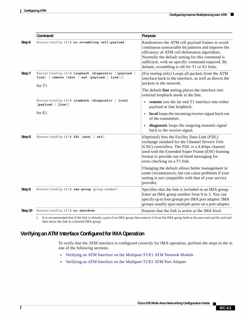
Configuring ATMConfiguring Inverse Multiplexing over ATM
WC-63Cisco IOS Wide-Area Networking Configuration Guide
Verifying an ATM Interface Configured for IMA Operation
To verify that the ATM interface is configured correctly for IMA operation, perform the steps in the in one of the following sections:
• Verifying an ATM Interface on the Multiport T1/E1 ATM Network Module
• Verifying an ATM Interface on the Multiport T1/E1 ATM Port Adapter
Step 6 Router(config-if)# no scrambling cell-payload Randomizes the ATM cell payload frames to avoid continuous nonvariable bit patterns and improve the efficiency of ATM cell delineation algorithms. Normally the default setting for this command is sufficient, with no specific command required. By default, scrambling is off for T1 or E1 links.
Step 7 Router(config-if)# loopback [diagnostic |[payload | line] | remote [iboc | esf [payload | line]]]
for T1
Router(config-if)# loopback [diagnostic | local [payload | line]]
for E1
(For testing only) Loops all packets from the ATM interface back to the interface, as well as directs the packets to the network.
The default line setting places the interface into external loopback mode at the line.
• remote sets the far end T1 interface into either payload or line loopback.
• local loops the incoming receive signal back out of the transmitter.
• diagnostic loops the outgoing transmit signal back to the receive signal.
Step 8 Router(config-if)# fdl {ansi | att} (Optional) Sets the Facility Data Link (FDL) exchange standard for the Channel Service Unit (CSU) controllers. The FDL is a 4-Kbps channel used with the Extended Super Frame (ESF) framing format to provide out-of-band messaging for error-checking on a T1 link.
Changing the default allows better management in some circumstances, but can cause problems if your setting is not compatible with that of your service provider.
Step 9 Router(config-if)# ima-group group-number1 Specifies that the link is included in an IMA group. Enter an IMA group number from 0 to 3. You can specify up to four groups per IMA port adapter. IMA groups usually span multiple ports on a port adapter.
Step 10 Router(config-if)# no shutdown Ensures that the link is active at the IMA level.
1. It is recommended that if the link is already a port of an IMA group then remove it from the IMA group both at the near end and far end and then move the link to a desired IMA group.
Command Purpose
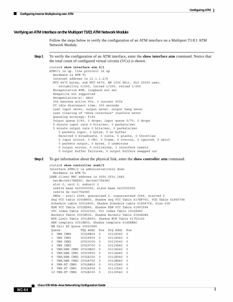
Configuring ATMConfiguring Inverse Multiplexing over ATM
WC-64Cisco IOS Wide-Area Networking Configuration Guide
Verifying an ATM Interface on the Multiport T1/E1 ATM Network Module
Follow the steps below to verify the configuration of an ATM interface on a Multiport T1/E1 ATM Network Module.
Step 1 To verify the configuration of an ATM interface, enter the show interface atm command. Notice that the total count of configured virtual circuits (VCs) is shown.
router# show interface atm 0/1ATM0/1 is up, line protocol is up Hardware is ATM T1 Internet address is 21.1.1.2/8 MTU 4470 bytes, sub MTU 4470, BW 1500 Kbit, DLY 20000 usec, reliability 0/255, txload 1/255, rxload 1/255 Encapsulation ATM, loopback not set Keepalive not supported Encapsulation(s): AAL5
256 maximum active VCs, 3 current VCCs VC idle disconnect time: 300 seconds Last input never, output never, output hang never Last clearing of "show interface" counters never Queueing strategy: fifo Output queue 0/40, 0 drops; input queue 0/75, 0 drops 5 minute input rate 0 bits/sec, 0 packets/sec 5 minute output rate 0 bits/sec, 0 packets/sec 0 packets input, 0 bytes, 0 no buffer Received 0 broadcasts, 0 runts, 0 giants, 0 throttles 0 input errors, 0 CRC, 0 frame, 0 overrun, 0 ignored, 0 abort 0 packets output, 0 bytes, 0 underruns 0 output errors, 0 collisions, 3 interface resets 0 output buffer failures, 0 output buffers swapped out
Step 2 To get information about the physical link, enter the show controller atm command.
router# show controller atm0/2Interface ATM0/2 is administratively down Hardware is ATM T1LANE client MAC address is 0050.0f0c.1482 hwidb=0x617BEE9C, ds=0x617D498C slot 0, unit 2, subunit 2 rs8234 base 0x3C000000, slave base 0x3C000000 rs8234 ds 0x617D498C SBDs - avail 2048, guaranteed 2, unguaranteed 2046, starved 0 Seg VCC table 3C00B800, Shadow Seg VCC Table 617EF76C, VCD Table 61805798 Schedule table 3C016800, Shadow Schedule table 618087C4, Size 63D RSM VCC Table 3C02ED80, Shadow RSM VCC Table 6180C994 VPI Index Table 3C02C300, VCI Index Table 3C02E980 Bucket2 Table 3C01E500, Shadow Bucket2 Table 6180A0E4 MCR Limit Table 3C01E900, Shadow MCR Table 617D2160 ABR template 3C01EB00, Shadow template 614DEEAC RM Cell RS Queue 3C02C980 Queue TXQ Addr Pos StQ Addr Pos 0 UBR CHN0 3C028B00 0 03118540 0 1 UBR CHN1 3C028F00 0 03118D40 0 2 UBR CHN2 3C029300 0 03119540 0 3 UBR CHN3 3C029700 0 03119D40 0 4 VBR/ABR CHN0 3C029B00 0 0311A540 0 5 VBR/ABR CHN1 3C029F00 0 0311AD40 0 6 VBR/ABR CHN2 3C02A300 0 0311B540 0 7 VBR/ABR CHN3 3C02A700 0 0311BD40 0 8 VBR-RT CHN0 3C02AB00 0 0311C540 0 9 VBR-RT CHN1 3C02AF00 0 0311CD40 0 10 VBR-RT CHN2 3C02B300 0 0311D540 0
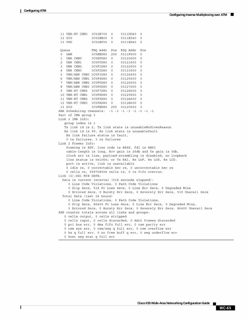
Configuring ATMConfiguring Inverse Multiplexing over ATM
WC-65Cisco IOS Wide-Area Networking Configuration Guide
11 VBR-RT CHN3 3C02B700 0 0311DD40 0 12 SIG 3C02BB00 0 0311E540 0 13 VPD 3C02BF00 0 0311ED40 0 Queue FBQ Addr Pos RSQ Addr Pos 0 OAM 3C0EED80 255 0311F600 0 1 UBR CHN0 3C0EFD80 0 03120600 0 2 UBR CHN1 3C0F0D80 0 03121600 0 3 UBR CHN2 3C0F1D80 0 03122600 0 4 UBR CHN3 3C0F2D80 0 03123600 0 5 VBR/ABR CHN0 3C0F3D80 0 03124600 0 6 VBR/ABR CHN1 3C0F4D80 0 03125600 0 7 VBR/ABR CHN2 3C0F5D80 0 03126600 0 8 VBR/ABR CHN3 3C0F6D80 0 03127600 0 9 VBR-RT CHN0 3C0F7D80 0 03128600 0 10 VBR-RT CHN1 3C0F8D80 0 03129600 0 11 VBR-RT CHN2 3C0F9D80 0 0312A600 0 12 VBR-RT CHN3 3C0FAD80 0 0312B600 0 13 SIG 3C0FBD80 255 0312C600 0SAR Scheduling channels: -1 -1 -1 -1 -1 -1 -1 -1Part of IMA group 3Link 2 IMA Info: group index is 1 Tx link id is 2, Tx link state is unusableNoGivenReason Rx link id is 99, Rx link state is unusableFault Rx link failure status is fault, 0 tx failures, 3 rx failuresLink 2 Framer Info: framing is ESF, line code is B8ZS, fdl is ANSI cable-length is long, Rcv gain is 26db and Tx gain is 0db, clock src is line, payload-scrambling is disabled, no loopback line status is 0x1064; or Tx RAI, Rx LOF, Rx LOS, Rx LCD. port is active, link is unavailable 0 idle rx, 0 correctable hec rx, 0 uncorrectable hec rx 0 cells rx, 599708004 cells tx, 0 rx fifo overrun.Link (2):DS1 MIB DATA: Data in current interval (518 seconds elapsed): 0 Line Code Violations, 0 Path Code Violations 0 Slip Secs, 518 Fr Loss Secs, 0 Line Err Secs, 0 Degraded Mins 0 Errored Secs, 0 Bursty Err Secs, 0 Severely Err Secs, 519 Unavail Secs Total Data (last 24 hours) 0 Line Code Violations, 0 Path Code Violations, 0 Slip Secs, 86400 Fr Loss Secs, 0 Line Err Secs, 0 Degraded Mins, 0 Errored Secs, 0 Bursty Err Secs, 0 Severely Err Secs, 86400 Unavail SecsSAR counter totals across all links and groups: 0 cells output, 0 cells stripped 0 cells input, 0 cells discarded, 0 AAL5 frames discarded 0 pci bus err, 0 dma fifo full err, 0 rsm parity err 0 rsm syn err, 0 rsm/seg q full err, 0 rsm overflow err 0 hs q full err, 0 no free buff q err, 0 seg underflow err 0 host seg stat q full err
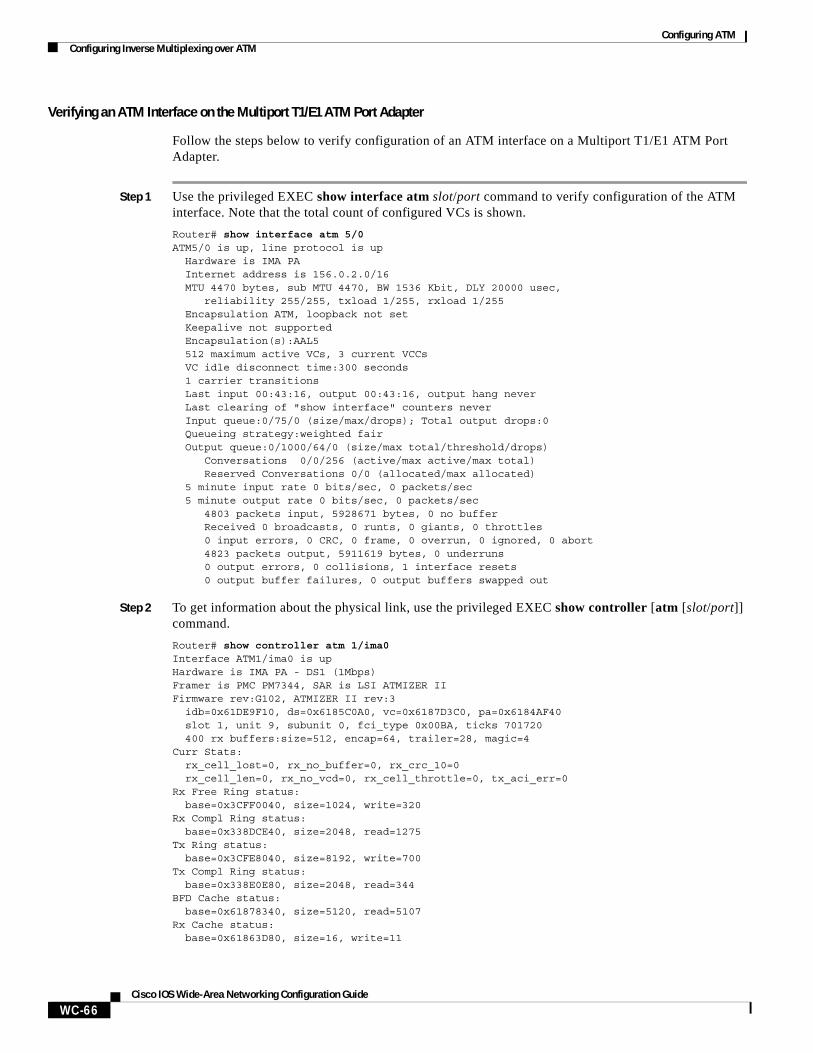
Configuring ATMConfiguring Inverse Multiplexing over ATM
WC-66Cisco IOS Wide-Area Networking Configuration Guide
Verifying an ATM Interface on the Multiport T1/E1 ATM Port Adapter
Follow the steps below to verify configuration of an ATM interface on a Multiport T1/E1 ATM Port Adapter.
Step 1 Use the privileged EXEC show interface atm slot/port command to verify configuration of the ATM interface. Note that the total count of configured VCs is shown.
Router# show interface atm 5/0ATM5/0 is up, line protocol is up Hardware is IMA PA Internet address is 156.0.2.0/16 MTU 4470 bytes, sub MTU 4470, BW 1536 Kbit, DLY 20000 usec, reliability 255/255, txload 1/255, rxload 1/255 Encapsulation ATM, loopback not set Keepalive not supported Encapsulation(s):AAL5 512 maximum active VCs, 3 current VCCs VC idle disconnect time:300 seconds 1 carrier transitions Last input 00:43:16, output 00:43:16, output hang never Last clearing of "show interface" counters never Input queue:0/75/0 (size/max/drops); Total output drops:0 Queueing strategy:weighted fair Output queue:0/1000/64/0 (size/max total/threshold/drops) Conversations 0/0/256 (active/max active/max total) Reserved Conversations 0/0 (allocated/max allocated) 5 minute input rate 0 bits/sec, 0 packets/sec 5 minute output rate 0 bits/sec, 0 packets/sec 4803 packets input, 5928671 bytes, 0 no buffer Received 0 broadcasts, 0 runts, 0 giants, 0 throttles 0 input errors, 0 CRC, 0 frame, 0 overrun, 0 ignored, 0 abort 4823 packets output, 5911619 bytes, 0 underruns 0 output errors, 0 collisions, 1 interface resets 0 output buffer failures, 0 output buffers swapped out
Step 2 To get information about the physical link, use the privileged EXEC show controller [atm [slot/port]] command.
Router# show controller atm 1/ima0Interface ATM1/ima0 is upHardware is IMA PA - DS1 (1Mbps)Framer is PMC PM7344, SAR is LSI ATMIZER IIFirmware rev:G102, ATMIZER II rev:3 idb=0x61DE9F10, ds=0x6185C0A0, vc=0x6187D3C0, pa=0x6184AF40 slot 1, unit 9, subunit 0, fci_type 0x00BA, ticks 701720 400 rx buffers:size=512, encap=64, trailer=28, magic=4Curr Stats: rx_cell_lost=0, rx_no_buffer=0, rx_crc_10=0 rx_cell_len=0, rx_no_vcd=0, rx_cell_throttle=0, tx_aci_err=0Rx Free Ring status: base=0x3CFF0040, size=1024, write=320Rx Compl Ring status: base=0x338DCE40, size=2048, read=1275Tx Ring status: base=0x3CFE8040, size=8192, write=700Tx Compl Ring status: base=0x338E0E80, size=2048, read=344BFD Cache status: base=0x61878340, size=5120, read=5107Rx Cache status: base=0x61863D80, size=16, write=11
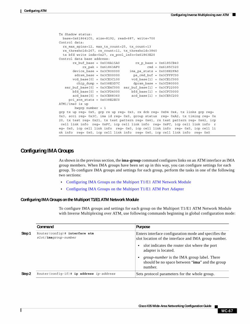
Configuring ATMConfiguring Inverse Multiplexing over ATM
WC-67Cisco IOS Wide-Area Networking Configuration Guide
Tx Shadow status: base=0x618641C0, size=8192, read=687, write=700Control data: rx_max_spins=12, max_tx_count=25, tx_count=13 rx_threshold=267, rx_count=11, tx_threshold=3840 tx bfd write indx=0x27, rx_pool_info=0x61863E20Control data base address: rx_buf_base = 0x038A15A0 rx_p_base = 0x6185CB40 rx_pak = 0x61863AF0 cmd = 0x6185C320 device_base = 0x3C800000 ima_pa_stats = 0x038E2FA0 sdram_base = 0x3CE00000 pa_cmd_buf = 0x3CFFFC00 vcd_base[0] = 0x3CE3C100 vcd_base[1] = 0x3CE1C000 chip_dump = 0x038E3D7C dpram_base = 0x3CD80000 sar_buf_base[0] = 0x3CE4C000 sar_buf_base[1] = 0x3CF22000 bfd_base[0] = 0x3CFD4000 bfd_base[1] = 0x3CFC0000 acd_base[0] = 0x3CE88360 acd_base[1] = 0x3CE5C200 pci_atm_stats = 0x038E2EC0ATM1/ima0 is up hwgrp number = 1grp tx up reg= 0x5, grp rx up reg= 0x3, rx dcb reg= 0xD4 0x4, tx links grp reg= 0x3, scci reg= 0x3C, ima id reg= 0x0, group status reg= 0xA2, tx timing reg= 0x20, tx test reg= 0x21, tx test pattern reg= 0x41, rx test pattern reg= 0x42, icp cell link info reg= 0xFC, icp cell link info reg= 0xFC, icp cell link info reg= 0x0, icp cell link info reg= 0x0, icp cell link info reg= 0x0, icp cell link info reg= 0x0, icp cell link info reg= 0x0, icp cell link info reg= 0x0
Configuring IMA Groups
As shown in the previous section, the ima-group command configures links on an ATM interface as IMA group members. When IMA groups have been set up in this way, you can configure settings for each group. To configure IMA groups and settings for each group, perform the tasks in one of the following two sections:
• Configuring IMA Groups on the Multiport T1/E1 ATM Network Module
• Configuring IMA Groups on the Multiport T1/E1 ATM Port Adapter
Configuring IMA Groups on the Multiport T1/E1 ATM Network Module
To configure IMA groups and settings for each group on the Multiport T1/E1 ATM Network Module with Inverse Multiplexing over ATM, use following commands beginning in global configuration mode:
Command Purpose
Step 1 Router(config)# interface atm slot/imagroup-number
Enters interface configuration mode and specifies the slot location of the interface and IMA group number.
• slot indicates the router slot where the port adapter is located.
• group-number is the IMA group label. There should be no space between “ima” and the group number.
Step 2 Router(config-if)# ip address ip-address Sets protocol parameters for the whole group.
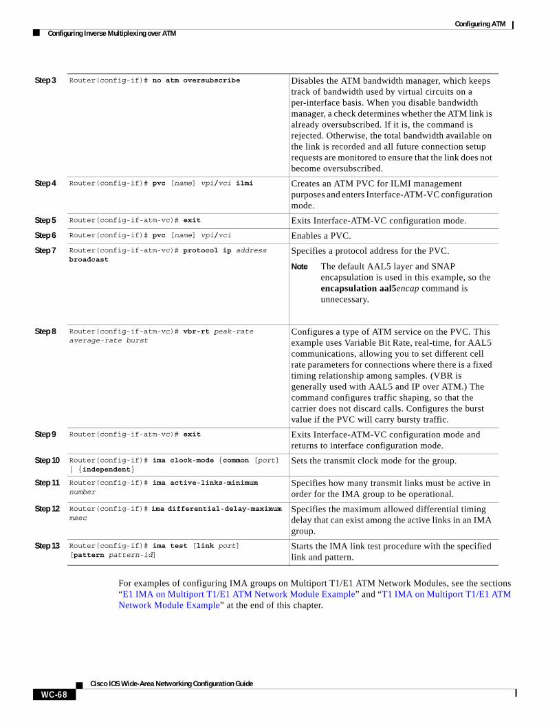
Configuring ATMConfiguring Inverse Multiplexing over ATM
WC-68Cisco IOS Wide-Area Networking Configuration Guide
For examples of configuring IMA groups on Multiport T1/E1 ATM Network Modules, see the sections “E1 IMA on Multiport T1/E1 ATM Network Module Example” and “T1 IMA on Multiport T1/E1 ATM Network Module Example” at the end of this chapter.
Step 3 Router(config-if)# no atm oversubscribe Disables the ATM bandwidth manager, which keeps track of bandwidth used by virtual circuits on a per-interface basis. When you disable bandwidth manager, a check determines whether the ATM link is already oversubscribed. If it is, the command is rejected. Otherwise, the total bandwidth available on the link is recorded and all future connection setup requests are monitored to ensure that the link does not become oversubscribed.
Step 4 Router(config-if)# pvc [name] vpi/vci ilmi Creates an ATM PVC for ILMI management purposes and enters Interface-ATM-VC configuration mode.
Step 5 Router(config-if-atm-vc)# exit Exits Interface-ATM-VC configuration mode.
Step 6 Router(config-if)# pvc [name] vpi/vci Enables a PVC.
Step 7 Router(config-if-atm-vc)# protocol ip address broadcast
Specifies a protocol address for the PVC.
Note The default AAL5 layer and SNAP encapsulation is used in this example, so the encapsulation aal5encap command is unnecessary.
Step 8 Router(config-if-atm-vc)# vbr-rt peak-rate average-rate burst
Configures a type of ATM service on the PVC. This example uses Variable Bit Rate, real-time, for AAL5 communications, allowing you to set different cell rate parameters for connections where there is a fixed timing relationship among samples. (VBR is generally used with AAL5 and IP over ATM.) The command configures traffic shaping, so that the carrier does not discard calls. Configures the burst value if the PVC will carry bursty traffic.
Step 9 Router(config-if-atm-vc)# exit Exits Interface-ATM-VC configuration mode and returns to interface configuration mode.
Step 10 Router(config-if)# ima clock-mode {common [port] | {independent}
Sets the transmit clock mode for the group.
Step 11 Router(config-if)# ima active-links-minimum number
Specifies how many transmit links must be active in order for the IMA group to be operational.
Step 12 Router(config-if)# ima differential-delay-maximum msec
Specifies the maximum allowed differential timing delay that can exist among the active links in an IMA group.
Step 13 Router(config-if)# ima test [link port][pattern pattern-id]
Starts the IMA link test procedure with the specified link and pattern.
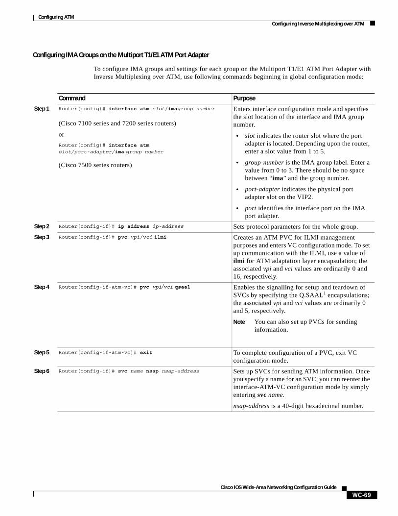
Configuring ATMConfiguring Inverse Multiplexing over ATM
WC-69Cisco IOS Wide-Area Networking Configuration Guide
Configuring IMA Groups on the Multiport T1/E1 ATM Port Adapter
To configure IMA groups and settings for each group on the Multiport T1/E1 ATM Port Adapter with Inverse Multiplexing over ATM, use following commands beginning in global configuration mode:
Command Purpose
Step 1 Router(config)# interface atm slot/imagroup number
(Cisco 7100 series and 7200 series routers)
or
Router(config)# interface atm slot/port-adapter/ima group number
(Cisco 7500 series routers)
Enters interface configuration mode and specifies the slot location of the interface and IMA group number.
• slot indicates the router slot where the port adapter is located. Depending upon the router, enter a slot value from 1 to 5.
• group-number is the IMA group label. Enter a value from 0 to 3. There should be no space between “ima” and the group number.
• port-adapter indicates the physical port adapter slot on the VIP2.
• port identifies the interface port on the IMA port adapter.
Step 2 Router(config-if)# ip address ip-address Sets protocol parameters for the whole group.
Step 3 Router(config-if)# pvc vpi/vci ilmi Creates an ATM PVC for ILMI management purposes and enters VC configuration mode. To set up communication with the ILMI, use a value of ilmi for ATM adaptation layer encapsulation; the associated vpi and vci values are ordinarily 0 and 16, respectively.
Step 4 Router(config-if-atm-vc)# pvc vpi/vci qsaal Enables the signalling for setup and teardown of SVCs by specifying the Q.SAAL1 encapsulations; the associated vpi and vci values are ordinarily 0 and 5, respectively.
Note You can also set up PVCs for sending information.
Step 5 Router(config-if-atm-vc)# exit To complete configuration of a PVC, exit VC configuration mode.
Step 6 Router(config-if)# svc name nsap nsap-address Sets up SVCs for sending ATM information. Once you specify a name for an SVC, you can reenter the interface-ATM-VC configuration mode by simply entering svc name.
nsap-address is a 40-digit hexadecimal number.
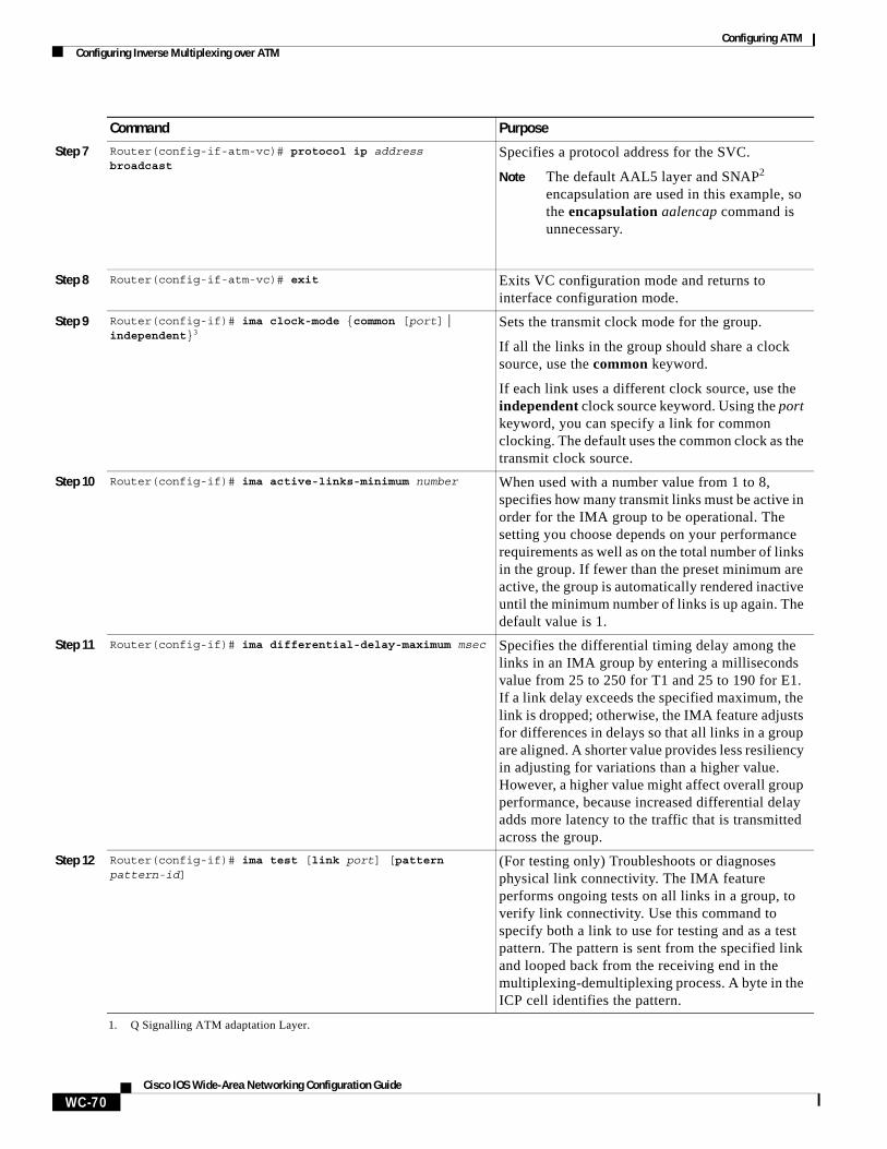
Configuring ATMConfiguring Inverse Multiplexing over ATM
WC-70Cisco IOS Wide-Area Networking Configuration Guide
Step 7 Router(config-if-atm-vc)# protocol ip address broadcast
Specifies a protocol address for the SVC.
Note The default AAL5 layer and SNAP2 encapsulation are used in this example, so the encapsulation aalencap command is unnecessary.
Step 8 Router(config-if-atm-vc)# exit Exits VC configuration mode and returns to interface configuration mode.
Step 9 Router(config-if)# ima clock-mode {common [port] | independent}3
Sets the transmit clock mode for the group.
If all the links in the group should share a clock source, use the common keyword.
If each link uses a different clock source, use the independent clock source keyword. Using the port keyword, you can specify a link for common clocking. The default uses the common clock as the transmit clock source.
Step 10 Router(config-if)# ima active-links-minimum number When used with a number value from 1 to 8, specifies how many transmit links must be active in order for the IMA group to be operational. The setting you choose depends on your performance requirements as well as on the total number of links in the group. If fewer than the preset minimum are active, the group is automatically rendered inactive until the minimum number of links is up again. The default value is 1.
Step 11 Router(config-if)# ima differential-delay-maximum msec Specifies the differential timing delay among the links in an IMA group by entering a milliseconds value from 25 to 250 for T1 and 25 to 190 for E1. If a link delay exceeds the specified maximum, the link is dropped; otherwise, the IMA feature adjusts for differences in delays so that all links in a group are aligned. A shorter value provides less resiliency in adjusting for variations than a higher value. However, a higher value might affect overall group performance, because increased differential delay adds more latency to the traffic that is transmitted across the group.
Step 12 Router(config-if)# ima test [link port] [pattern pattern-id]
(For testing only) Troubleshoots or diagnoses physical link connectivity. The IMA feature performs ongoing tests on all links in a group, to verify link connectivity. Use this command to specify both a link to use for testing and as a test pattern. The pattern is sent from the specified link and looped back from the receiving end in the multiplexing-demultiplexing process. A byte in the ICP cell identifies the pattern.
1. Q Signalling ATM adaptation Layer.
Command Purpose
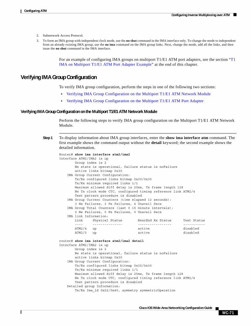
Configuring ATMConfiguring Inverse Multiplexing over ATM
WC-71Cisco IOS Wide-Area Networking Configuration Guide
For an example of configuring IMA groups on multiport T1/E1 ATM port adapters, see the section “T1 IMA on Multiport T1/E1 ATM Port Adapter Example” at the end of this chapter.
Verifying IMA Group Configuration
To verify IMA group configuration, perform the steps in one of the following two sections:
• Verifying IMA Group Configuration on the Multiport T1/E1 ATM Network Module
• Verifying IMA Group Configuration on the Multiport T1/E1 ATM Port Adapter
Verifying IMA Group Configuration on the Multiport T1/E1 ATM Network Module
Perform the following steps to verify IMA group configuration on the Multiport T1/E1 ATM Network Module.
Step 1 To display information about IMA group interfaces, enter the show ima interface atm command. The first example shows the command output without the detail keyword; the second example shows the detailed information.
Router# show ima interface atm2/ima2Interface ATM2/IMA2 is up Group index is 2 Ne state is operational, failure status is noFailure active links bitmap 0x30 IMA Group Current Configuration: Tx/Rx configured links bitmap 0x30/0x30 Tx/Rx minimum required links 1/1 Maximum allowed diff delay is 25ms, Tx frame length 128 Ne Tx clock mode CTC, configured timing reference link ATM2/4 Test pattern procedure is disabled IMA Group Current Counters (time elapsed 12 seconds): 3 Ne Failures, 3 Fe Failures, 4 Unavail Secs IMA Group Total Counters (last 0 15 minute intervals): 0 Ne Failures, 0 Fe Failures, 0 Unavail Secs IMA link Information: Link Physical Status NearEnd Rx Status Test Status ---- --------------- ----------------- ----------- ATM2/4 up active disabled ATM2/5 up active disabled
router# show ima interface atm2/ima2 detail Interface ATM2/IMA2 is up Group index is 2 Ne state is operational, failure status is noFailure active links bitmap 0x30 IMA Group Current Configuration: Tx/Rx configured links bitmap 0x30/0x30 Tx/Rx minimum required links 1/1 Maximum allowed diff delay is 25ms, Tx frame length 128 Ne Tx clock mode CTC, configured timing reference link ATM2/4 Test pattern procedure is disabled Detailed group Information: Tx/Rx Ima_id 0x22/0x40, symmetry symmetricOperation
2. Subnetwork Access Protocol.
3. To form an IMA group with independent clock mode, use the no shut command in the IMA interface only. To change the mode to independent from an already existing IMA group, use the no ima command on the IMA group links. Next, change the mode, add all the links, and then issue the no shut command in the IMA interface.
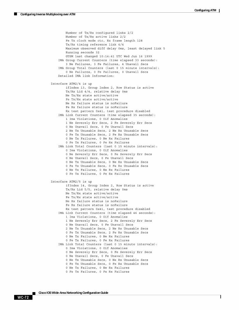
Configuring ATMConfiguring Inverse Multiplexing over ATM
WC-72Cisco IOS Wide-Area Networking Configuration Guide
Number of Tx/Rx configured links 2/2 Number of Tx/Rx active links 2/2 Fe Tx clock mode ctc, Rx frame length 128 Tx/Rx timing reference link 4/4 Maximum observed diff delay 0ms, least delayed link 5 Running seconds 32 GTSM last changed 10:14:41 UTC Wed Jun 16 1999 IMA Group Current Counters (time elapsed 33 seconds): 3 Ne Failures, 3 Fe Failures, 4 Unavail Secs IMA Group Total Counters (last 0 15 minute intervals): 0 Ne Failures, 0 Fe Failures, 0 Unavail Secs Detailed IMA link Information: Interface ATM2/4 is up ifIndex 13, Group Index 2, Row Status is active Tx/Rx Lid 4/4, relative delay 0ms Ne Tx/Rx state active/active Fe Tx/Rx state active/active Ne Rx failure status is noFailure Fe Rx failure status is noFailure Rx test pattern 0x41, test procedure disabled IMA Link Current Counters (time elapsed 35 seconds): 1 Ima Violations, 0 Oif Anomalies 1 Ne Severely Err Secs, 2 Fe Severely Err Secs 0 Ne Unavail Secs, 0 Fe Unavail Secs 2 Ne Tx Unusable Secs, 2 Ne Rx Unusable Secs 0 Fe Tx Unusable Secs, 2 Fe Rx Unusable Secs 0 Ne Tx Failures, 0 Ne Rx Failures 0 Fe Tx Failures, 0 Fe Rx Failures IMA Link Total Counters (last 0 15 minute intervals): 0 Ima Violations, 0 Oif Anomalies 0 Ne Severely Err Secs, 0 Fe Severely Err Secs 0 Ne Unavail Secs, 0 Fe Unavail Secs 0 Ne Tx Unusable Secs, 0 Ne Rx Unusable Secs 0 Fe Tx Unusable Secs, 0 Fe Rx Unusable Secs 0 Ne Tx Failures, 0 Ne Rx Failures 0 Fe Tx Failures, 0 Fe Rx Failures Interface ATM2/5 is up ifIndex 14, Group Index 2, Row Status is active Tx/Rx Lid 5/5, relative delay 0ms Ne Tx/Rx state active/active Fe Tx/Rx state active/active Ne Rx failure status is noFailure Fe Rx failure status is noFailure Rx test pattern 0x41, test procedure disabled IMA Link Current Counters (time elapsed 46 seconds): 1 Ima Violations, 0 Oif Anomalies 1 Ne Severely Err Secs, 2 Fe Severely Err Secs 0 Ne Unavail Secs, 0 Fe Unavail Secs 2 Ne Tx Unusable Secs, 2 Ne Rx Unusable Secs 0 Fe Tx Unusable Secs, 2 Fe Rx Unusable Secs 0 Ne Tx Failures, 0 Ne Rx Failures 0 Fe Tx Failures, 0 Fe Rx Failures IMA Link Total Counters (last 0 15 minute intervals): 0 Ima Violations, 0 Oif Anomalies 0 Ne Severely Err Secs, 0 Fe Severely Err Secs 0 Ne Unavail Secs, 0 Fe Unavail Secs 0 Ne Tx Unusable Secs, 0 Ne Rx Unusable Secs 0 Fe Tx Unusable Secs, 0 Fe Rx Unusable Secs 0 Ne Tx Failures, 0 Ne Rx Failures 0 Fe Tx Failures, 0 Fe Rx Failures
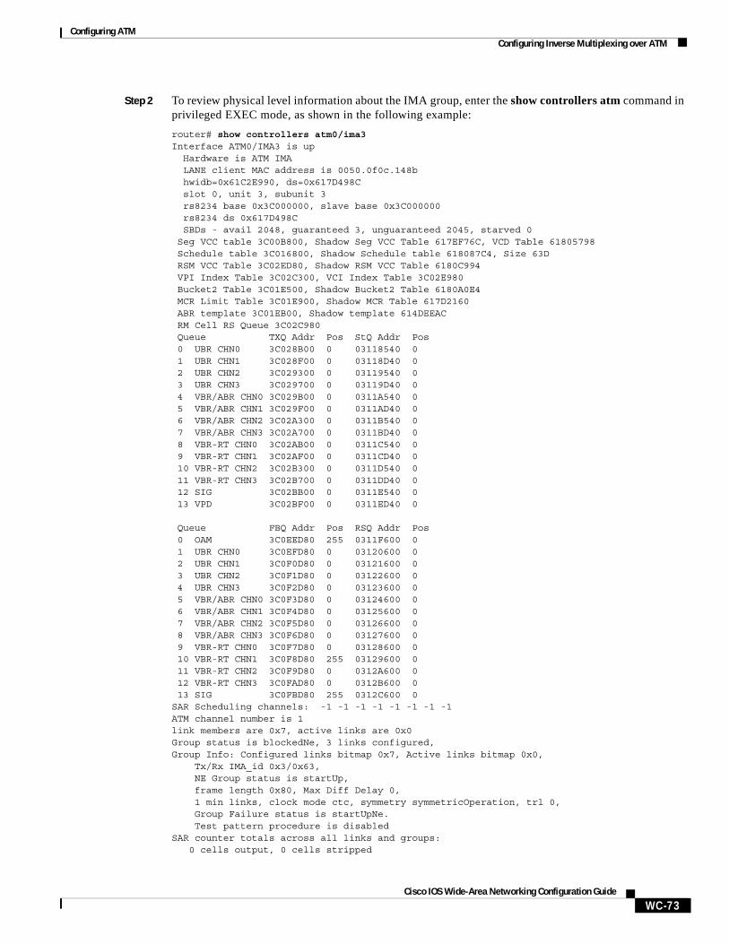
Configuring ATMConfiguring Inverse Multiplexing over ATM
WC-73Cisco IOS Wide-Area Networking Configuration Guide
Step 2 To review physical level information about the IMA group, enter the show controllers atm command in privileged EXEC mode, as shown in the following example:
router# show controllers atm0/ima3Interface ATM0/IMA3 is up Hardware is ATM IMA LANE client MAC address is 0050.0f0c.148b hwidb=0x61C2E990, ds=0x617D498C slot 0, unit 3, subunit 3 rs8234 base 0x3C000000, slave base 0x3C000000 rs8234 ds 0x617D498C SBDs - avail 2048, guaranteed 3, unguaranteed 2045, starved 0 Seg VCC table 3C00B800, Shadow Seg VCC Table 617EF76C, VCD Table 61805798 Schedule table 3C016800, Shadow Schedule table 618087C4, Size 63D RSM VCC Table 3C02ED80, Shadow RSM VCC Table 6180C994 VPI Index Table 3C02C300, VCI Index Table 3C02E980 Bucket2 Table 3C01E500, Shadow Bucket2 Table 6180A0E4 MCR Limit Table 3C01E900, Shadow MCR Table 617D2160 ABR template 3C01EB00, Shadow template 614DEEAC RM Cell RS Queue 3C02C980 Queue TXQ Addr Pos StQ Addr Pos 0 UBR CHN0 3C028B00 0 03118540 0 1 UBR CHN1 3C028F00 0 03118D40 0 2 UBR CHN2 3C029300 0 03119540 0 3 UBR CHN3 3C029700 0 03119D40 0 4 VBR/ABR CHN0 3C029B00 0 0311A540 0 5 VBR/ABR CHN1 3C029F00 0 0311AD40 0 6 VBR/ABR CHN2 3C02A300 0 0311B540 0 7 VBR/ABR CHN3 3C02A700 0 0311BD40 0 8 VBR-RT CHN0 3C02AB00 0 0311C540 0 9 VBR-RT CHN1 3C02AF00 0 0311CD40 0 10 VBR-RT CHN2 3C02B300 0 0311D540 0 11 VBR-RT CHN3 3C02B700 0 0311DD40 0 12 SIG 3C02BB00 0 0311E540 0 13 VPD 3C02BF00 0 0311ED40 0 Queue FBQ Addr Pos RSQ Addr Pos 0 OAM 3C0EED80 255 0311F600 0 1 UBR CHN0 3C0EFD80 0 03120600 0 2 UBR CHN1 3C0F0D80 0 03121600 0 3 UBR CHN2 3C0F1D80 0 03122600 0 4 UBR CHN3 3C0F2D80 0 03123600 0 5 VBR/ABR CHN0 3C0F3D80 0 03124600 0 6 VBR/ABR CHN1 3C0F4D80 0 03125600 0 7 VBR/ABR CHN2 3C0F5D80 0 03126600 0 8 VBR/ABR CHN3 3C0F6D80 0 03127600 0 9 VBR-RT CHN0 3C0F7D80 0 03128600 0 10 VBR-RT CHN1 3C0F8D80 255 03129600 0 11 VBR-RT CHN2 3C0F9D80 0 0312A600 0 12 VBR-RT CHN3 3C0FAD80 0 0312B600 0 13 SIG 3C0FBD80 255 0312C600 0SAR Scheduling channels: -1 -1 -1 -1 -1 -1 -1 -1ATM channel number is 1link members are 0x7, active links are 0x0Group status is blockedNe, 3 links configured,Group Info: Configured links bitmap 0x7, Active links bitmap 0x0, Tx/Rx IMA_id 0x3/0x63, NE Group status is startUp, frame length 0x80, Max Diff Delay 0, 1 min links, clock mode ctc, symmetry symmetricOperation, trl 0, Group Failure status is startUpNe. Test pattern procedure is disabledSAR counter totals across all links and groups: 0 cells output, 0 cells stripped
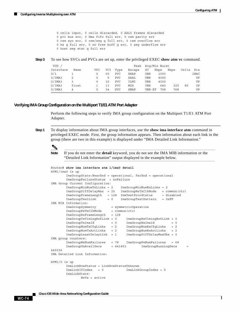
Configuring ATMConfiguring Inverse Multiplexing over ATM
WC-74Cisco IOS Wide-Area Networking Configuration Guide
0 cells input, 0 cells discarded, 0 AAL5 frames discarded 0 pci bus err, 0 dma fifo full err, 0 rsm parity err 0 rsm syn err, 0 rsm/seg q full err, 0 rsm overflow err 0 hs q full err, 0 no free buff q err, 0 seg underflow err 0 host seg stat q full err
Step 3 To see how SVCs and PVCs are set up, enter the privileged EXEC show atm vc command.
VCD / Peak Avg/Min BurstInterface Name VPI VCI Type Encaps SC Kbps Kbps Cells Sts0/1 1 0 50 PVC SNAP UBR 1000 INAC0/IMA3 2 0 5 PVC SAAL UBR 4000 UP0/IMA3 3 0 16 PVC ILMI UBR 4000 UP0/IMA3 first 1 13 PVC MUX VBR 640 320 80 UP0/IMA3 4 0 34 SVC SNAP VBR-RT 768 768 UP
Verifying IMA Group Configuration on the Multiport T1/E1 ATM Port Adapter
Perform the following steps to verify IMA group configuration on the Multiport T1/E1 ATM Port Adapter.
Step 1 To display information about IMA group interfaces, use the show ima interface atm command in privileged EXEC mode. First, the group information appears. Then information about each link in the group (there are two in this example) is displayed under “IMA Detailed Link Information.”
Note If you do not enter the detail keyword, you do not see the IMA MIB information or the “Detailed Link Information” output displayed in the example below.
Router# show ima interface atm 1/ima0 detailATM1/ima0 is up ImaGroupState:NearEnd = operational, FarEnd = operational ImaGroupFailureStatus = noFailureIMA Group Current Configuration: ImaGroupMinNumTxLinks = 2 ImaGroupMinNumRxLinks = 2 ImaGroupDiffDelayMax = 25 ImaGroupNeTxClkMode = common(ctc) ImaGroupFrameLength = 128 ImaTestProcStatus = disabled ImaGroupTestLink = 0 ImaGroupTestPattern = 0xFFIMA MIB Information: ImaGroupSymmetry = symmetricOperation ImaGroupFeTxClkMode = common(ctc) ImaGroupRxFrameLength = 128 ImaGroupTxTimingRefLink = 0 ImaGroupRxTimingRefLink = 0 ImaGroupTxImaId = 0 ImaGroupRxImaId = 0 ImaGroupNumTxCfgLinks = 2 ImaGroupNumRxCfgLinks = 2 ImaGroupNumTxActLinks = 2 ImaGroupNumRxActLinks = 2 ImaGroupLeastDelayLink = 1 ImaGroupDiffDelayMaxObs = 0IMA group counters: ImaGroupNeNumFailures = 78 ImaGroupFeNumFailures = 68 ImaGroupUnAvailSecs = 441453 ImaGroupRunningSecs =445036IMA Detailed Link Information:
ATM1/0 is up ImaLinkRowStatus = LinkRowStatusUnknown ImaLinkIfIndex = 0 ImaLinkGroupIndex = 0 ImaLinkState: NeTx = active
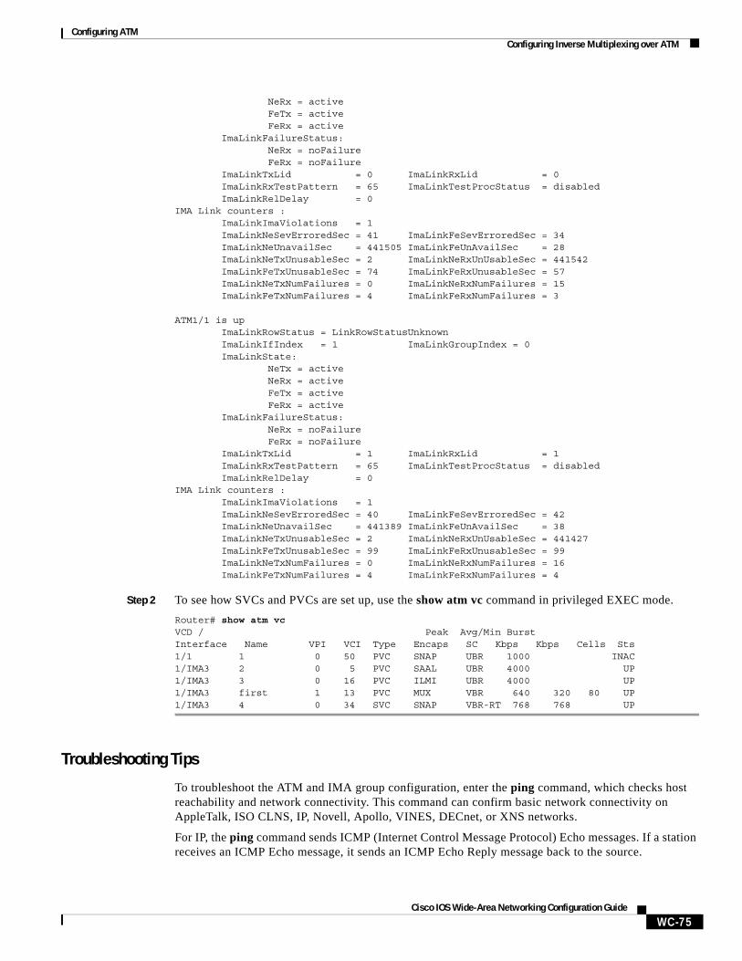
Configuring ATMConfiguring Inverse Multiplexing over ATM
WC-75Cisco IOS Wide-Area Networking Configuration Guide
NeRx = active FeTx = active FeRx = active ImaLinkFailureStatus: NeRx = noFailure FeRx = noFailure ImaLinkTxLid = 0 ImaLinkRxLid = 0 ImaLinkRxTestPattern = 65 ImaLinkTestProcStatus = disabled ImaLinkRelDelay = 0IMA Link counters : ImaLinkImaViolations = 1 ImaLinkNeSevErroredSec = 41 ImaLinkFeSevErroredSec = 34 ImaLinkNeUnavailSec = 441505 ImaLinkFeUnAvailSec = 28 ImaLinkNeTxUnusableSec = 2 ImaLinkNeRxUnUsableSec = 441542 ImaLinkFeTxUnusableSec = 74 ImaLinkFeRxUnusableSec = 57 ImaLinkNeTxNumFailures = 0 ImaLinkNeRxNumFailures = 15 ImaLinkFeTxNumFailures = 4 ImaLinkFeRxNumFailures = 3
ATM1/1 is up ImaLinkRowStatus = LinkRowStatusUnknown ImaLinkIfIndex = 1 ImaLinkGroupIndex = 0 ImaLinkState: NeTx = active NeRx = active FeTx = active FeRx = active ImaLinkFailureStatus: NeRx = noFailure FeRx = noFailure ImaLinkTxLid = 1 ImaLinkRxLid = 1 ImaLinkRxTestPattern = 65 ImaLinkTestProcStatus = disabled ImaLinkRelDelay = 0IMA Link counters : ImaLinkImaViolations = 1 ImaLinkNeSevErroredSec = 40 ImaLinkFeSevErroredSec = 42 ImaLinkNeUnavailSec = 441389 ImaLinkFeUnAvailSec = 38 ImaLinkNeTxUnusableSec = 2 ImaLinkNeRxUnUsableSec = 441427 ImaLinkFeTxUnusableSec = 99 ImaLinkFeRxUnusableSec = 99 ImaLinkNeTxNumFailures = 0 ImaLinkNeRxNumFailures = 16 ImaLinkFeTxNumFailures = 4 ImaLinkFeRxNumFailures = 4
Step 2 To see how SVCs and PVCs are set up, use the show atm vc command in privileged EXEC mode.
Router# show atm vcVCD / Peak Avg/Min BurstInterface Name VPI VCI Type Encaps SC Kbps Kbps Cells Sts1/1 1 0 50 PVC SNAP UBR 1000 INAC1/IMA3 2 0 5 PVC SAAL UBR 4000 UP1/IMA3 3 0 16 PVC ILMI UBR 4000 UP1/IMA3 first 1 13 PVC MUX VBR 640 320 80 UP1/IMA3 4 0 34 SVC SNAP VBR-RT 768 768 UP
Troubleshooting Tips
To troubleshoot the ATM and IMA group configuration, enter the ping command, which checks host reachability and network connectivity. This command can confirm basic network connectivity on AppleTalk, ISO CLNS, IP, Novell, Apollo, VINES, DECnet, or XNS networks.
For IP, the ping command sends ICMP (Internet Control Message Protocol) Echo messages. If a station receives an ICMP Echo message, it sends an ICMP Echo Reply message back to the source.
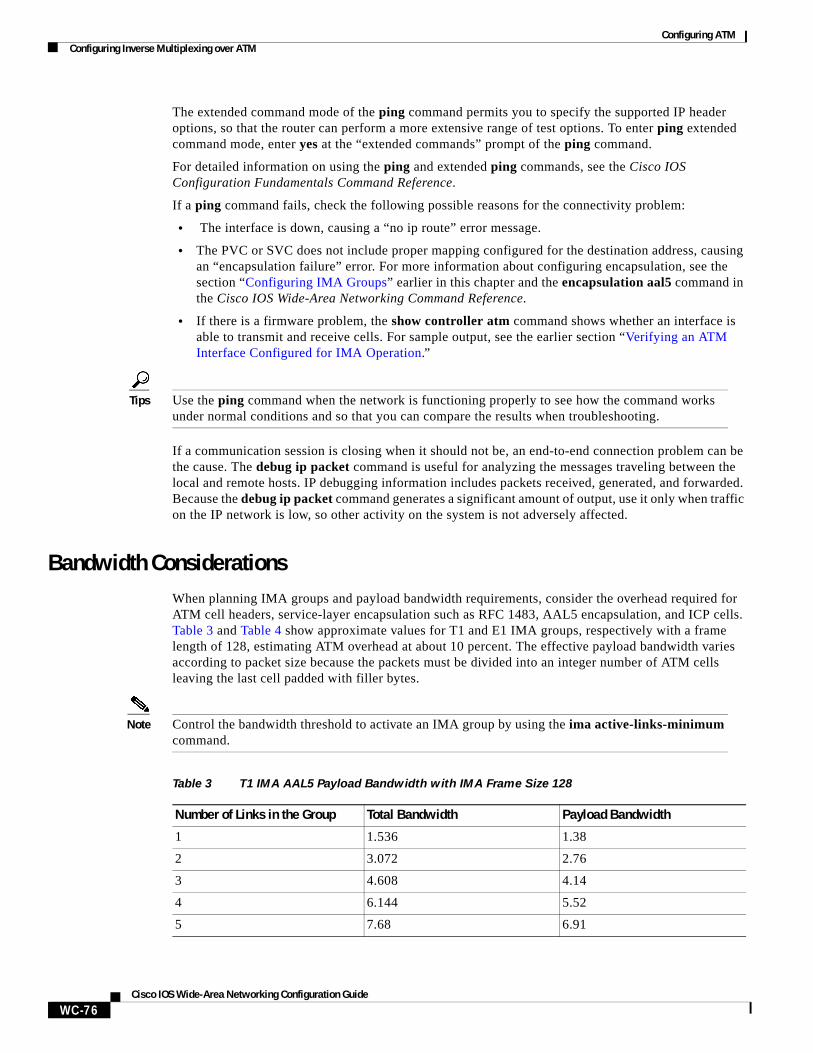
Configuring ATMConfiguring Inverse Multiplexing over ATM
WC-76Cisco IOS Wide-Area Networking Configuration Guide
The extended command mode of the ping command permits you to specify the supported IP header options, so that the router can perform a more extensive range of test options. To enter ping extended command mode, enter yes at the “extended commands” prompt of the ping command.
For detailed information on using the ping and extended ping commands, see the Cisco IOS Configuration Fundamentals Command Reference.
If a ping command fails, check the following possible reasons for the connectivity problem:
• The interface is down, causing a “no ip route” error message.
• The PVC or SVC does not include proper mapping configured for the destination address, causing an “encapsulation failure” error. For more information about configuring encapsulation, see the section “Configuring IMA Groups” earlier in this chapter and the encapsulation aal5 command in the Cisco IOS Wide-Area Networking Command Reference.
• If there is a firmware problem, the show controller atm command shows whether an interface is able to transmit and receive cells. For sample output, see the earlier section “Verifying an ATM Interface Configured for IMA Operation.”
Tips Use the ping command when the network is functioning properly to see how the command works under normal conditions and so that you can compare the results when troubleshooting.
If a communication session is closing when it should not be, an end-to-end connection problem can be the cause. The debug ip packet command is useful for analyzing the messages traveling between the local and remote hosts. IP debugging information includes packets received, generated, and forwarded. Because the debug ip packet command generates a significant amount of output, use it only when traffic on the IP network is low, so other activity on the system is not adversely affected.
Bandwidth ConsiderationsWhen planning IMA groups and payload bandwidth requirements, consider the overhead required for ATM cell headers, service-layer encapsulation such as RFC 1483, AAL5 encapsulation, and ICP cells. Table 3 and Table 4 show approximate values for T1 and E1 IMA groups, respectively with a frame length of 128, estimating ATM overhead at about 10 percent. The effective payload bandwidth varies according to packet size because the packets must be divided into an integer number of ATM cells leaving the last cell padded with filler bytes.
Note Control the bandwidth threshold to activate an IMA group by using the ima active-links-minimum command.
Table 3 T1 IMA AAL5 Payload Bandwidth with IMA Frame Size 128
Number of Links in the Group Total Bandwidth Payload Bandwidth
1 1.536 1.38
2 3.072 2.76
3 4.608 4.14
4 6.144 5.52
5 7.68 6.91
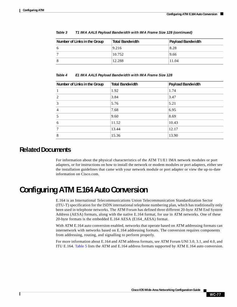
Configuring ATMConfiguring ATM E.164 Auto Conversion
WC-77Cisco IOS Wide-Area Networking Configuration Guide
Related DocumentsFor information about the physical characteristics of the ATM T1/E1 IMA network modules or port adapters, or for instructions on how to install the network or modem modules or port adapters, either see the installation guidelines that came with your network module or port adapter or view the up-to-date information on Cisco.com.
Configuring ATM E.164 Auto ConversionE.164 is an International Telecommunications Union Telecommunication Standardization Sector (ITU-T) specification for the ISDN international telephone numbering plan, which has traditionally only been used in telephone networks. The ATM Forum has defined three different 20-byte ATM End System Address (AESA) formats, along with the native E.164 format, for use in ATM networks. One of these 20-byte formats is the embedded E.164 AESA (E164_AESA) format.
With ATM E.164 auto conversion enabled, networks that operate based on ATM addressing formats can internetwork with networks based on E.164 addressing formats. The conversion requires components from addressing, routing, and signalling to perform properly.
For more information about E.164 and ATM address formats, see ATM Forum UNI 3.0, 3.1, and 4.0, and ITU E.164. Table 5 lists the ATM and E.164 address formats supported by ATM E.164 auto conversion.
6 9.216 8.28
7 10.752 9.66
8 12.288 11.04
Table 4 E1 IMA AAL5 Payload Bandwidth with IMA Frame Size 128
Number of Links in the Group Total Bandwidth Payload Bandwidth
1 1.92 1.74
2 3.84 3.47
3 5.76 5.21
4 7.68 6.95
5 9.60 8.69
6 11.52 10.43
7 13.44 12.17
8 15.36 13.90
Table 3 T1 IMA AAL5 Payload Bandwidth with IMA Frame Size 128 (continued)
Number of Links in the Group Total Bandwidth Payload Bandwidth
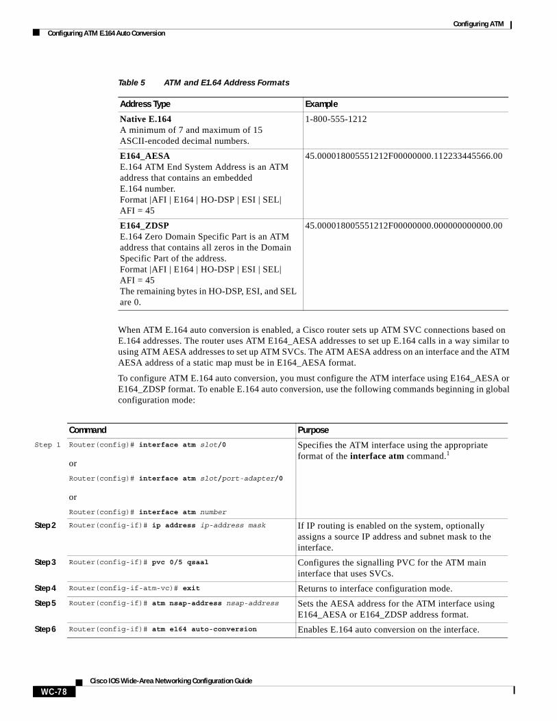
Configuring ATMConfiguring ATM E.164 Auto Conversion
WC-78Cisco IOS Wide-Area Networking Configuration Guide
When ATM E.164 auto conversion is enabled, a Cisco router sets up ATM SVC connections based on E.164 addresses. The router uses ATM E164_AESA addresses to set up E.164 calls in a way similar to using ATM AESA addresses to set up ATM SVCs. The ATM AESA address on an interface and the ATM AESA address of a static map must be in E164_AESA format.
To configure ATM E.164 auto conversion, you must configure the ATM interface using E164_AESA or E164_ZDSP format. To enable E.164 auto conversion, use the following commands beginning in global configuration mode:
Table 5 ATM and E1.64 Address Formats
Address Type Example
Native E.164A minimum of 7 and maximum of 15 ASCII-encoded decimal numbers.
1-800-555-1212
E164_AESAE.164 ATM End System Address is an ATM address that contains an embedded E.164 number.Format |AFI | E164 | HO-DSP | ESI | SEL| AFI = 45
45.000018005551212F00000000.112233445566.00
E164_ZDSPE.164 Zero Domain Specific Part is an ATM address that contains all zeros in the Domain Specific Part of the address.Format |AFI | E164 | HO-DSP | ESI | SEL| AFI = 45The remaining bytes in HO-DSP, ESI, and SEL are 0.
45.000018005551212F00000000.000000000000.00
Command Purpose
Step 1 Router(config)# interface atm slot/0
or
Router(config)# interface atm slot/port-adapter/0
or
Router(config)# interface atm number
Specifies the ATM interface using the appropriate format of the interface atm command.1
Step 2 Router(config-if)# ip address ip-address mask If IP routing is enabled on the system, optionally assigns a source IP address and subnet mask to the interface.
Step 3 Router(config-if)# pvc 0/5 qsaal Configures the signalling PVC for the ATM main interface that uses SVCs.
Step 4 Router(config-if-atm-vc)# exit Returns to interface configuration mode.
Step 5 Router(config-if)# atm nsap-address nsap-address Sets the AESA address for the ATM interface using E164_AESA or E164_ZDSP address format.
Step 6 Router(config-if)# atm e164 auto-conversion Enables E.164 auto conversion on the interface.
Configuring ATMConfiguring Circuit Emulation Services
WC-79Cisco IOS Wide-Area Networking Configuration Guide
Use the show interfaces atm command to verify that ATM E.164 auto conversion is running.
For an example of configuring ATM E.164 auto conversion, refer to the section “Configuring ATM E.164 Auto Conversion Example” at the end of this chapter.
Configuring Circuit Emulation Services For overview information and configuration tasks for Circuit Emulation Services (CES) for ATM, see the following sections:
• CES Overview
• Configuring CES on the OC-3/STM-1 ATM Circuit Emulation Service Network Module
• Configuring CES on the ATM-CES Port Adapter
• Configuring Virtual Path Shaping
CES OverviewCircuit emulation service internetworking function (CES-IWF) is a service based on ATM Forum standards that allows communications to occur between CBR or AAL1 CES and ATM UNI interfaces; that is, between non-ATM telephony devices (such as classic PBXs or TDMs) and ATM devices (such as Cisco 3600 or 7200 series routers). Thus, a Cisco 3600 series router equipped with an OC-3/STM-1 ATM Circuit Emulation Service network module or a Cisco 7200 series router equipped with an ATM-CES port adapter offers a migration path from classic T1/E1 CBR data communications services to emulated CES T1/E1 unstructured (clear channel) services or structured (N x 64) services in an ATM network.
Figure 6 shows a simplified representation of CES-IWF functions in an ATM network.
Step 7 Router(config-if)# svc [name] nsap address Specifies the destination NSAP address using E164_AESA or E164_ZDSP address format.
Step 8 Router(config-if-atm-vc)# protocol ip protocol-address
Specifies the destination IP address of the SVC.
1. To determine the correct form of the interface atm command, consult your ATM network module, port adapter, or router documentation.
Command Purpose
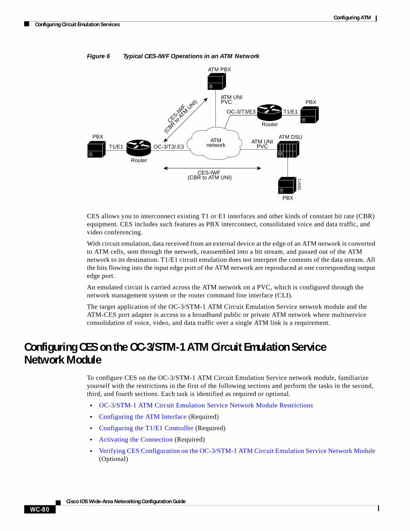
Configuring ATMConfiguring Circuit Emulation Services
WC-80Cisco IOS Wide-Area Networking Configuration Guide
Figure 6 Typical CES-IWF Operations in an ATM Network
CES allows you to interconnect existing T1 or E1 interfaces and other kinds of constant bit rate (CBR) equipment. CES includes such features as PBX interconnect, consolidated voice and data traffic, and video conferencing.
With circuit emulation, data received from an external device at the edge of an ATM network is converted to ATM cells, sent through the network, reassembled into a bit stream, and passed out of the ATM network to its destination. T1/E1 circuit emulation does not interpret the contents of the data stream. All the bits flowing into the input edge port of the ATM network are reproduced at one corresponding output edge port.
An emulated circuit is carried across the ATM network on a PVC, which is configured through the network management system or the router command line interface (CLI).
The target application of the OC-3/STM-1 ATM Circuit Emulation Service network module and the ATM-CES port adapter is access to a broadband public or private ATM network where multiservice consolidation of voice, video, and data traffic over a single ATM link is a requirement.
Configuring CES on the OC-3/STM-1 ATM Circuit Emulation Service Network Module
To configure CES on the OC-3/STM-1 ATM Circuit Emulation Service network module, familiarize yourself with the restrictions in the first of the following sections and perform the tasks in the second, third, and fourth sections. Each task is identified as required or optional.
• OC-3/STM-1 ATM Circuit Emulation Service Network Module Restrictions
• Configuring the ATM Interface (Required)
• Configuring the T1/E1 Controller (Required)
• Activating the Connection (Required)
• Verifying CES Configuration on the OC-3/STM-1 ATM Circuit Emulation Service Network Module (Optional)
ATM PBX
PBX
PBX
OC-3/T3/.E3
OC-3/T3/E3
T1/E1
T1/E1
ATM UNIPVC
ATM UNIPVC
ATM DSU
S59
71
CES-IWF (CBR to ATM UNI)
CES-IWF
(CBR to
ATM
UNI)
Router
Router
ATMnetwork
PBX
Configuring ATMConfiguring Circuit Emulation Services
WC-81Cisco IOS Wide-Area Networking Configuration Guide
Note The configuration tasks in these sections are supported only on the OC-3/STM-1 ATM Circuit Emulation Service network module.
For an example of configuring CES on an OC-3/STM-1 ATM Circuit Emulation Service network module, see the section “Configuring CES on an OC-3/STM-1 ATM Circuit Emulation Services Network Module Example” at the end of this chapter.
OC-3/STM-1 ATM Circuit Emulation Service Network Module Restrictions
The OC-3/STM-1 ATM CES network module can be configured with the following restrictions:
• The OC-3/STM-1 ATM CES network module requires Cisco IOS Release 12.1(2)T or later.
• On-hook detection is not supported.
• If you configure an ABR VC, either in a vc-class or in vcmode, the minimum guaranteed cell rate (MCR) value you enter is ignored, and an MCR of 0 is used, although this is not apparent from the configuration. Additionally, ABR PCR values are configurable in a range from 0 to line rate. The MCR is honored, however. Currently, the OC-3/STM-1 ATM CES network module rounds the configured value down to one of the following values:
– 64 Kbps
– 384 K
– 768 K
– 1,534 K
– 2 M
– 4 M
– 10 M
– 16 M
– 25.6 M
– 44 M
– 75 M
– 100 M
– 125 M
– 149 M
• When you configure a UBR+ VC, the Cisco CLI requires that you specify a peak cell rate (PCR). Because of a hardware limitation, any value you enter is ignored by the OC-3/STM-1 ATM CES network module and a value of 155 Mbits per second is used.
• The OC-3/STM-1 ATM CES network module does not allow configuring interfaces and subinterfaces by using the traffic-shape parameter. That is because the OC-3/STM-1 ATM CES network module supports traffic shaping through native ATM means by making a traffic class for UBR, UBR+, ABR, VBR-rt, VBR-ntr, and CBR.
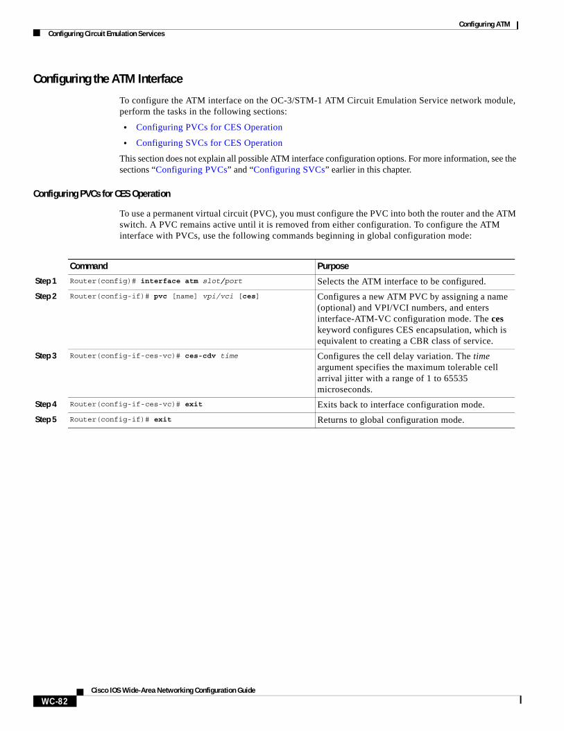
Configuring ATMConfiguring Circuit Emulation Services
WC-82Cisco IOS Wide-Area Networking Configuration Guide
Configuring the ATM Interface
To configure the ATM interface on the OC-3/STM-1 ATM Circuit Emulation Service network module, perform the tasks in the following sections:
• Configuring PVCs for CES Operation
• Configuring SVCs for CES Operation
This section does not explain all possible ATM interface configuration options. For more information, see the sections “Configuring PVCs” and “Configuring SVCs” earlier in this chapter.
Configuring PVCs for CES Operation
To use a permanent virtual circuit (PVC), you must configure the PVC into both the router and the ATM switch. A PVC remains active until it is removed from either configuration. To configure the ATM interface with PVCs, use the following commands beginning in global configuration mode:
Command Purpose
Step 1 Router(config)# interface atm slot/port Selects the ATM interface to be configured.
Step 2 Router(config-if)# pvc [name] vpi/vci [ces] Configures a new ATM PVC by assigning a name (optional) and VPI/VCI numbers, and enters interface-ATM-VC configuration mode. The ces keyword configures CES encapsulation, which is equivalent to creating a CBR class of service.
Step 3 Router(config-if-ces-vc)# ces-cdv time Configures the cell delay variation. The time argument specifies the maximum tolerable cell arrival jitter with a range of 1 to 65535 microseconds.
Step 4 Router(config-if-ces-vc)# exit Exits back to interface configuration mode.
Step 5 Router(config-if)# exit Returns to global configuration mode.
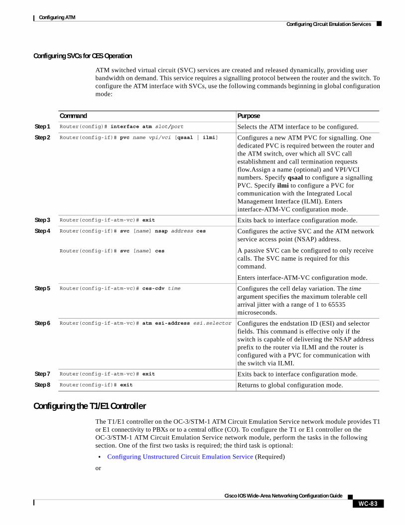
Configuring ATMConfiguring Circuit Emulation Services
WC-83Cisco IOS Wide-Area Networking Configuration Guide
Configuring SVCs for CES Operation
ATM switched virtual circuit (SVC) services are created and released dynamically, providing user bandwidth on demand. This service requires a signalling protocol between the router and the switch. To configure the ATM interface with SVCs, use the following commands beginning in global configuration mode:
Configuring the T1/E1 Controller
The T1/E1 controller on the OC-3/STM-1 ATM Circuit Emulation Service network module provides T1 or E1 connectivity to PBXs or to a central office (CO). To configure the T1 or E1 controller on the OC-3/STM-1 ATM Circuit Emulation Service network module, perform the tasks in the following section. One of the first two tasks is required; the third task is optional:
• Configuring Unstructured Circuit Emulation Service (Required)
or
Command Purpose
Step 1 Router(config)# interface atm slot/port Selects the ATM interface to be configured.
Step 2 Router(config-if)# pvc name vpi/vci [qsaal | ilmi] Configures a new ATM PVC for signalling. One dedicated PVC is required between the router and the ATM switch, over which all SVC call establishment and call termination requests flow.Assign a name (optional) and VPI/VCI numbers. Specify qsaal to configure a signalling PVC. Specify ilmi to configure a PVC for communication with the Integrated Local Management Interface (ILMI). Enters interface-ATM-VC configuration mode.
Step 3 Router(config-if-atm-vc)# exit Exits back to interface configuration mode.
Step 4 Router(config-if)# svc [name] nsap address ces
Router(config-if)# svc [name] ces
Configures the active SVC and the ATM network service access point (NSAP) address.
A passive SVC can be configured to only receive calls. The SVC name is required for this command.
Enters interface-ATM-VC configuration mode.
Step 5 Router(config-if-atm-vc)# ces-cdv time Configures the cell delay variation. The time argument specifies the maximum tolerable cell arrival jitter with a range of 1 to 65535 microseconds.
Step 6 Router(config-if-atm-vc)# atm esi-address esi.selector Configures the endstation ID (ESI) and selector fields. This command is effective only if the switch is capable of delivering the NSAP address prefix to the router via ILMI and the router is configured with a PVC for communication with the switch via ILMI.
Step 7 Router(config-if-atm-vc)# exit Exits back to interface configuration mode.
Step 8 Router(config-if)# exit Returns to global configuration mode.
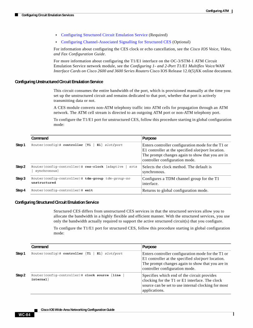
Configuring ATMConfiguring Circuit Emulation Services
WC-84Cisco IOS Wide-Area Networking Configuration Guide
• Configuring Structured Circuit Emulation Service (Required)
• Configuring Channel-Associated Signalling for Structured CES (Optional)
For information about configuring the CES clock or echo cancellation, see the Cisco IOS Voice, Video, and Fax Configuration Guide.
For more information about configuring the T1/E1 interface on the OC-3/STM-1 ATM Circuit Emulation Service network module, see the Configuring 1- and 2-Port T1/E1 Multiflex Voice/WAN Interface Cards on Cisco 2600 and 3600 Series Routers Cisco IOS Release 12.0(5)XK online document.
Configuring Unstructured Circuit Emulation Service
This circuit consumes the entire bandwidth of the port, which is provisioned manually at the time you set up the unstructured circuit and remains dedicated to that port, whether that port is actively transmitting data or not.
A CES module converts non-ATM telephony traffic into ATM cells for propagation through an ATM network. The ATM cell stream is directed to an outgoing ATM port or non-ATM telephony port.
To configure the T1/E1 port for unstructured CES, follow this procedure starting in global configuration mode:
Configuring Structured Circuit Emulation Service
Structured CES differs from unstructured CES services in that the structured services allow you to allocate the bandwidth in a highly flexible and efficient manner. With the structured services, you use only the bandwidth actually required to support the active structured circuit(s) that you configure.
To configure the T1/E1 port for structured CES, follow this procedure starting in global configuration mode:
Command Purpose
Step 1 Router(config)# controller {T1 | E1} slot/port Enters controller configuration mode for the T1 or E1 controller at the specified slot/port location. The prompt changes again to show that you are in controller configuration mode.
Step 2 Router(config-controller)# ces-clock [adaptive | srts | synchronous]
Selects the clock method. The default is synchronous.
Step 3 Router(config-controller)# tdm-group tdm-group-no unstructured
Configures a TDM channel group for the T1 interface.
Step 4 Router(config-controller)# exit Returns to global configuration mode.
Command Purpose
Step 1 Router(config)# controller {T1 | E1} slot/port Enters controller configuration mode for the T1 or E1 controller at the specified slot/port location. The prompt changes again to show that you are in controller configuration mode.
Step 2 Router(config-controller)# clock source {line | internal}
Specifies which end of the circuit provides clocking for the T1 or E1 interface. The clock source can be set to use internal clocking for most applications.
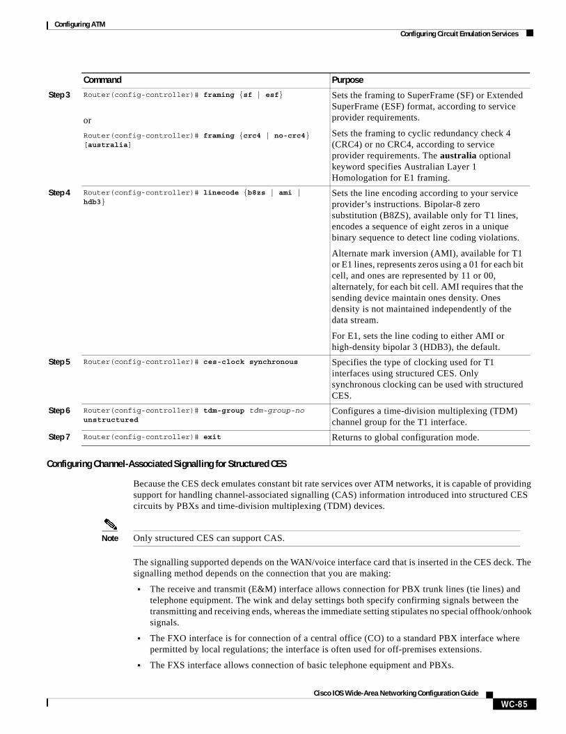
Configuring ATMConfiguring Circuit Emulation Services
WC-85Cisco IOS Wide-Area Networking Configuration Guide
Configuring Channel-Associated Signalling for Structured CES
Because the CES deck emulates constant bit rate services over ATM networks, it is capable of providing support for handling channel-associated signalling (CAS) information introduced into structured CES circuits by PBXs and time-division multiplexing (TDM) devices.
Note Only structured CES can support CAS.
The signalling supported depends on the WAN/voice interface card that is inserted in the CES deck. The signalling method depends on the connection that you are making:
• The receive and transmit (E&M) interface allows connection for PBX trunk lines (tie lines) and telephone equipment. The wink and delay settings both specify confirming signals between the transmitting and receiving ends, whereas the immediate setting stipulates no special offhook/onhook signals.
• The FXO interface is for connection of a central office (CO) to a standard PBX interface where permitted by local regulations; the interface is often used for off-premises extensions.
• The FXS interface allows connection of basic telephone equipment and PBXs.
Step 3 Router(config-controller)# framing {sf | esf}
or
Router(config-controller)# framing {crc4 | no-crc4} [australia]
Sets the framing to SuperFrame (SF) or Extended SuperFrame (ESF) format, according to service provider requirements.
Sets the framing to cyclic redundancy check 4 (CRC4) or no CRC4, according to service provider requirements. The australia optional keyword specifies Australian Layer 1 Homologation for E1 framing.
Step 4 Router(config-controller)# linecode {b8zs | ami | hdb3}
Sets the line encoding according to your service provider’s instructions. Bipolar-8 zero substitution (B8ZS), available only for T1 lines, encodes a sequence of eight zeros in a unique binary sequence to detect line coding violations.
Alternate mark inversion (AMI), available for T1 or E1 lines, represents zeros using a 01 for each bit cell, and ones are represented by 11 or 00, alternately, for each bit cell. AMI requires that the sending device maintain ones density. Ones density is not maintained independently of the data stream.
For E1, sets the line coding to either AMI or high-density bipolar 3 (HDB3), the default.
Step 5 Router(config-controller)# ces-clock synchronous Specifies the type of clocking used for T1 interfaces using structured CES. Only synchronous clocking can be used with structured CES.
Step 6 Router(config-controller)# tdm-group tdm-group-no unstructured
Configures a time-division multiplexing (TDM) channel group for the T1 interface.
Step 7 Router(config-controller)# exit Returns to global configuration mode.
Command Purpose
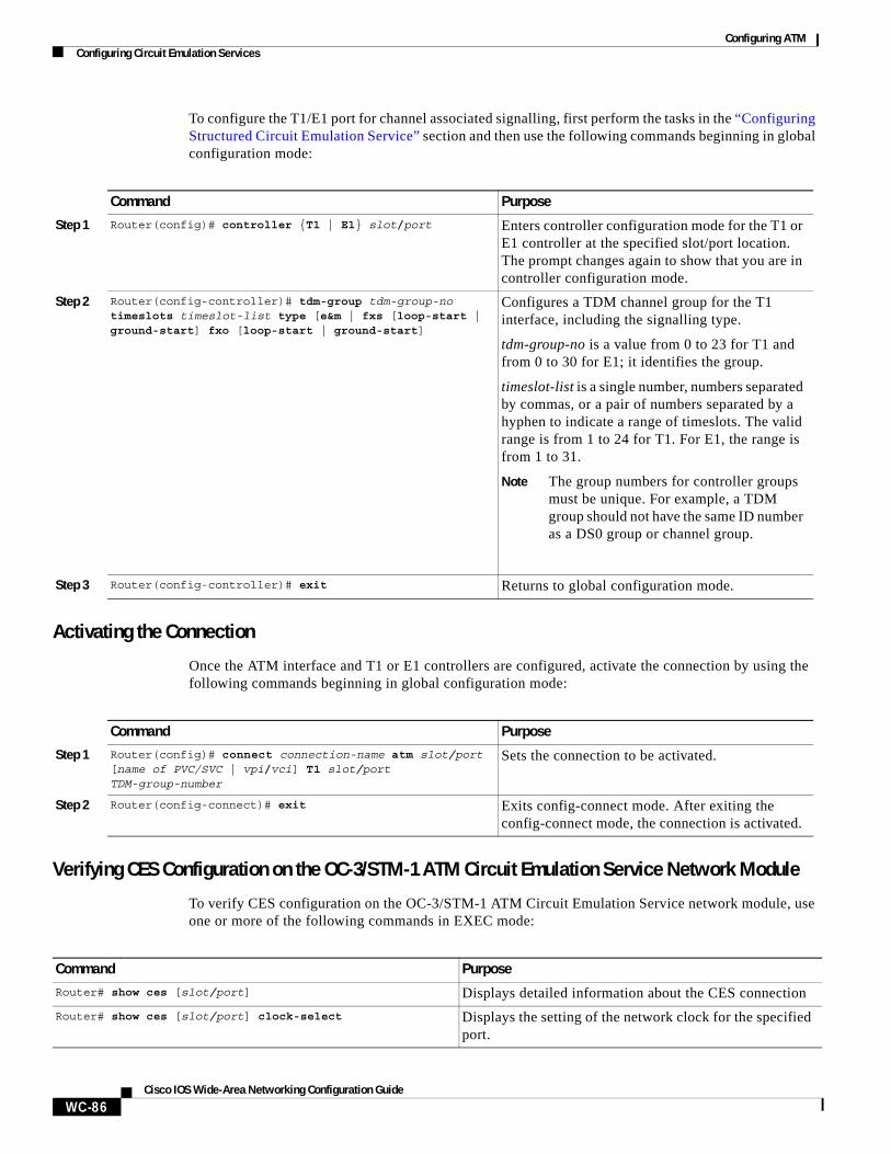
Configuring ATMConfiguring Circuit Emulation Services
WC-86Cisco IOS Wide-Area Networking Configuration Guide
To configure the T1/E1 port for channel associated signalling, first perform the tasks in the “Configuring Structured Circuit Emulation Service” section and then use the following commands beginning in global configuration mode:
Activating the Connection
Once the ATM interface and T1 or E1 controllers are configured, activate the connection by using the following commands beginning in global configuration mode:
Verifying CES Configuration on the OC-3/STM-1 ATM Circuit Emulation Service Network Module
To verify CES configuration on the OC-3/STM-1 ATM Circuit Emulation Service network module, use one or more of the following commands in EXEC mode:
Command Purpose
Step 1 Router(config)# controller {T1 | E1} slot/port Enters controller configuration mode for the T1 or E1 controller at the specified slot/port location. The prompt changes again to show that you are in controller configuration mode.
Step 2 Router(config-controller)# tdm-group tdm-group-no timeslots timeslot-list type [e&m | fxs [loop-start | ground-start] fxo [loop-start | ground-start]
Configures a TDM channel group for the T1 interface, including the signalling type.
tdm-group-no is a value from 0 to 23 for T1 and from 0 to 30 for E1; it identifies the group.
timeslot-list is a single number, numbers separated by commas, or a pair of numbers separated by a hyphen to indicate a range of timeslots. The valid range is from 1 to 24 for T1. For E1, the range is from 1 to 31.
Note The group numbers for controller groups must be unique. For example, a TDM group should not have the same ID number as a DS0 group or channel group.
Step 3 Router(config-controller)# exit Returns to global configuration mode.
Command Purpose
Step 1 Router(config)# connect connection-name atm slot/port [name of PVC/SVC | vpi/vci] T1 slot/port TDM-group-number
Sets the connection to be activated.
Step 2 Router(config-connect)# exit Exits config-connect mode. After exiting the config-connect mode, the connection is activated.
Command Purpose
Router# show ces [slot/port] Displays detailed information about the CES connection
Router# show ces [slot/port] clock-select Displays the setting of the network clock for the specified port.
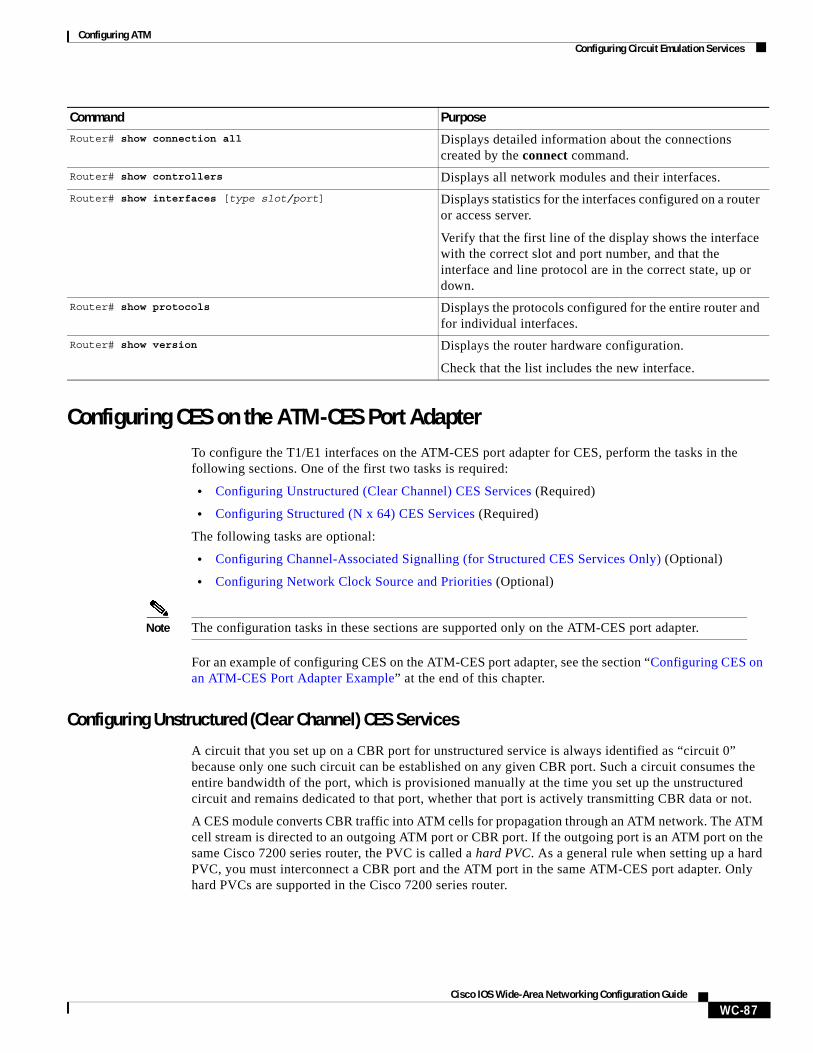
Configuring ATMConfiguring Circuit Emulation Services
WC-87Cisco IOS Wide-Area Networking Configuration Guide
Configuring CES on the ATM-CES Port AdapterTo configure the T1/E1 interfaces on the ATM-CES port adapter for CES, perform the tasks in the following sections. One of the first two tasks is required:
• Configuring Unstructured (Clear Channel) CES Services (Required)
• Configuring Structured (N x 64) CES Services (Required)
The following tasks are optional:
• Configuring Channel-Associated Signalling (for Structured CES Services Only) (Optional)
• Configuring Network Clock Source and Priorities (Optional)
Note The configuration tasks in these sections are supported only on the ATM-CES port adapter.
For an example of configuring CES on the ATM-CES port adapter, see the section “Configuring CES on an ATM-CES Port Adapter Example” at the end of this chapter.
Configuring Unstructured (Clear Channel) CES Services
A circuit that you set up on a CBR port for unstructured service is always identified as “circuit 0” because only one such circuit can be established on any given CBR port. Such a circuit consumes the entire bandwidth of the port, which is provisioned manually at the time you set up the unstructured circuit and remains dedicated to that port, whether that port is actively transmitting CBR data or not.
A CES module converts CBR traffic into ATM cells for propagation through an ATM network. The ATM cell stream is directed to an outgoing ATM port or CBR port. If the outgoing port is an ATM port on the same Cisco 7200 series router, the PVC is called a hard PVC. As a general rule when setting up a hard PVC, you must interconnect a CBR port and the ATM port in the same ATM-CES port adapter. Only hard PVCs are supported in the Cisco 7200 series router.
Router# show connection all Displays detailed information about the connections created by the connect command.
Router# show controllers Displays all network modules and their interfaces.
Router# show interfaces [type slot/port] Displays statistics for the interfaces configured on a router or access server.
Verify that the first line of the display shows the interface with the correct slot and port number, and that the interface and line protocol are in the correct state, up or down.
Router# show protocols Displays the protocols configured for the entire router and for individual interfaces.
Router# show version Displays the router hardware configuration.
Check that the list includes the new interface.
Command Purpose
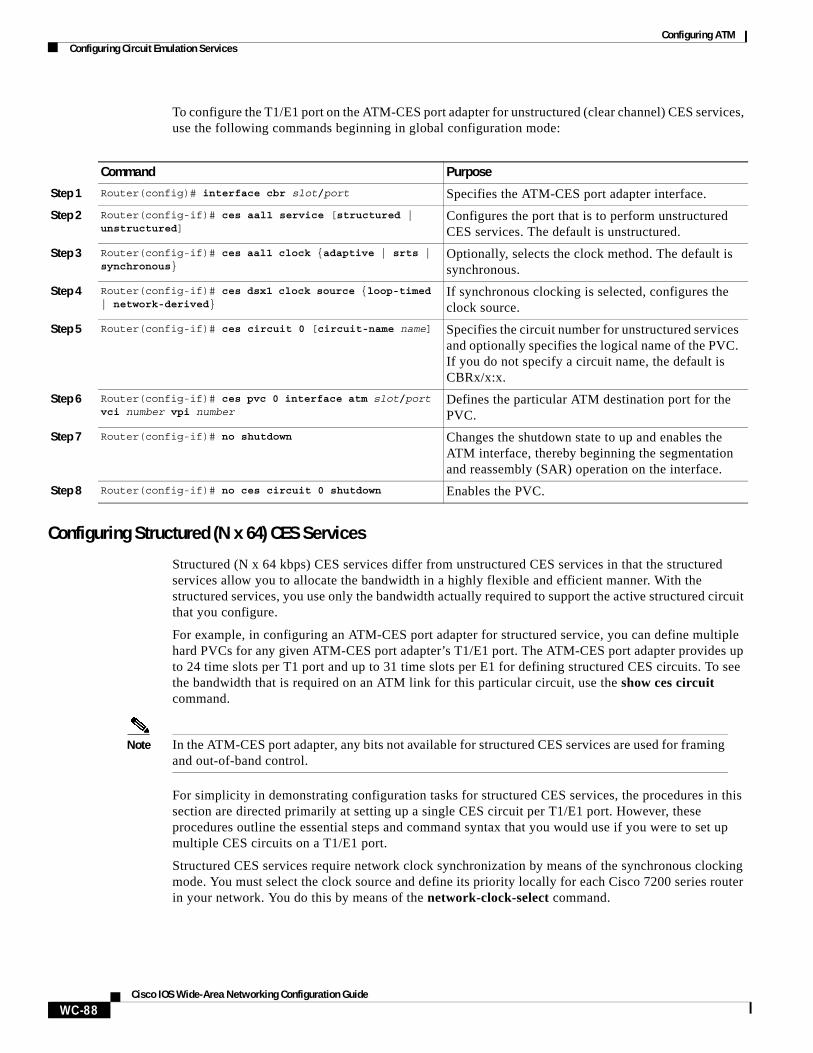
Configuring ATMConfiguring Circuit Emulation Services
WC-88Cisco IOS Wide-Area Networking Configuration Guide
To configure the T1/E1 port on the ATM-CES port adapter for unstructured (clear channel) CES services, use the following commands beginning in global configuration mode:
Configuring Structured (N x 64) CES Services
Structured (N x 64 kbps) CES services differ from unstructured CES services in that the structured services allow you to allocate the bandwidth in a highly flexible and efficient manner. With the structured services, you use only the bandwidth actually required to support the active structured circuit that you configure.
For example, in configuring an ATM-CES port adapter for structured service, you can define multiple hard PVCs for any given ATM-CES port adapter’s T1/E1 port. The ATM-CES port adapter provides up to 24 time slots per T1 port and up to 31 time slots per E1 for defining structured CES circuits. To see the bandwidth that is required on an ATM link for this particular circuit, use the show ces circuit command.
Note In the ATM-CES port adapter, any bits not available for structured CES services are used for framing and out-of-band control.
For simplicity in demonstrating configuration tasks for structured CES services, the procedures in this section are directed primarily at setting up a single CES circuit per T1/E1 port. However, these procedures outline the essential steps and command syntax that you would use if you were to set up multiple CES circuits on a T1/E1 port.
Structured CES services require network clock synchronization by means of the synchronous clocking mode. You must select the clock source and define its priority locally for each Cisco 7200 series router in your network. You do this by means of the network-clock-select command.
Command Purpose
Step 1 Router(config)# interface cbr slot/port Specifies the ATM-CES port adapter interface.
Step 2 Router(config-if)# ces aal1 service [structured | unstructured]
Configures the port that is to perform unstructured CES services. The default is unstructured.
Step 3 Router(config-if)# ces aal1 clock {adaptive | srts | synchronous}
Optionally, selects the clock method. The default is synchronous.
Step 4 Router(config-if)# ces dsx1 clock source {loop-timed | network-derived}
If synchronous clocking is selected, configures the clock source.
Step 5 Router(config-if)# ces circuit 0 [circuit-name name] Specifies the circuit number for unstructured services and optionally specifies the logical name of the PVC. If you do not specify a circuit name, the default is CBRx/x:x.
Step 6 Router(config-if)# ces pvc 0 interface atm slot/port vci number vpi number
Defines the particular ATM destination port for the PVC.
Step 7 Router(config-if)# no shutdown Changes the shutdown state to up and enables the ATM interface, thereby beginning the segmentation and reassembly (SAR) operation on the interface.
Step 8 Router(config-if)# no ces circuit 0 shutdown Enables the PVC.
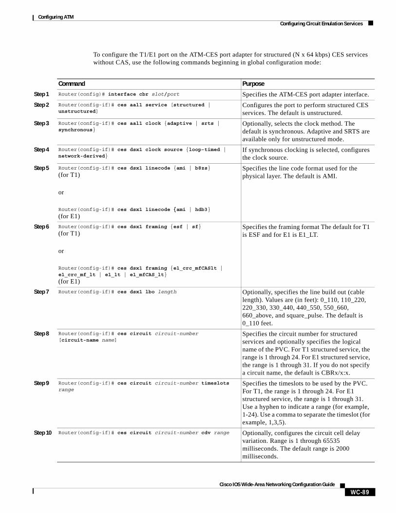
Configuring ATMConfiguring Circuit Emulation Services
WC-89Cisco IOS Wide-Area Networking Configuration Guide
To configure the T1/E1 port on the ATM-CES port adapter for structured (N x 64 kbps) CES services without CAS, use the following commands beginning in global configuration mode:
Command Purpose
Step 1 Router(config)# interface cbr slot/port Specifies the ATM-CES port adapter interface.
Step 2 Router(config-if)# ces aal1 service [structured | unstructured]
Configures the port to perform structured CES services. The default is unstructured.
Step 3 Router(config-if)# ces aal1 clock {adaptive | srts | synchronous}
Optionally, selects the clock method. The default is synchronous. Adaptive and SRTS are available only for unstructured mode.
Step 4 Router(config-if)# ces dsx1 clock source {loop-timed | network-derived}
If synchronous clocking is selected, configures the clock source.
Step 5 Router(config-if)# ces dsx1 linecode {ami | b8zs}
(for T1)
or
Router(config-if)# ces dsx1 linecode {ami | hdb3}
(for E1)
Specifies the line code format used for the physical layer. The default is AMI.
Step 6 Router(config-if)# ces dsx1 framing {esf | sf}
(for T1)
or
Router(config-if)# ces dsx1 framing {e1_crc_mfCASlt | e1_crc_mf_lt | e1_lt | e1_mfCAS_lt}
(for E1)
Specifies the framing format The default for T1 is ESF and for E1 is E1_LT.
Step 7 Router(config-if)# ces dsx1 lbo length Optionally, specifies the line build out (cable length). Values are (in feet): 0_110, 110_220, 220_330, 330_440, 440_550, 550_660, 660_above, and square_pulse. The default is 0_110 feet.
Step 8 Router(config-if)# ces circuit circuit-number [circuit-name name]
Specifies the circuit number for structured services and optionally specifies the logical name of the PVC. For T1 structured service, the range is 1 through 24. For E1 structured service, the range is 1 through 31. If you do not specify a circuit name, the default is CBRx/x:x.
Step 9 Router(config-if)# ces circuit circuit-number timeslots range
Specifies the timeslots to be used by the PVC. For T1, the range is 1 through 24. For E1 structured service, the range is 1 through 31. Use a hyphen to indicate a range (for example, 1-24). Use a comma to separate the timeslot (for example, 1,3,5).
Step 10 Router(config-if)# ces circuit circuit-number cdv range Optionally, configures the circuit cell delay variation. Range is 1 through 65535 milliseconds. The default range is 2000 milliseconds.
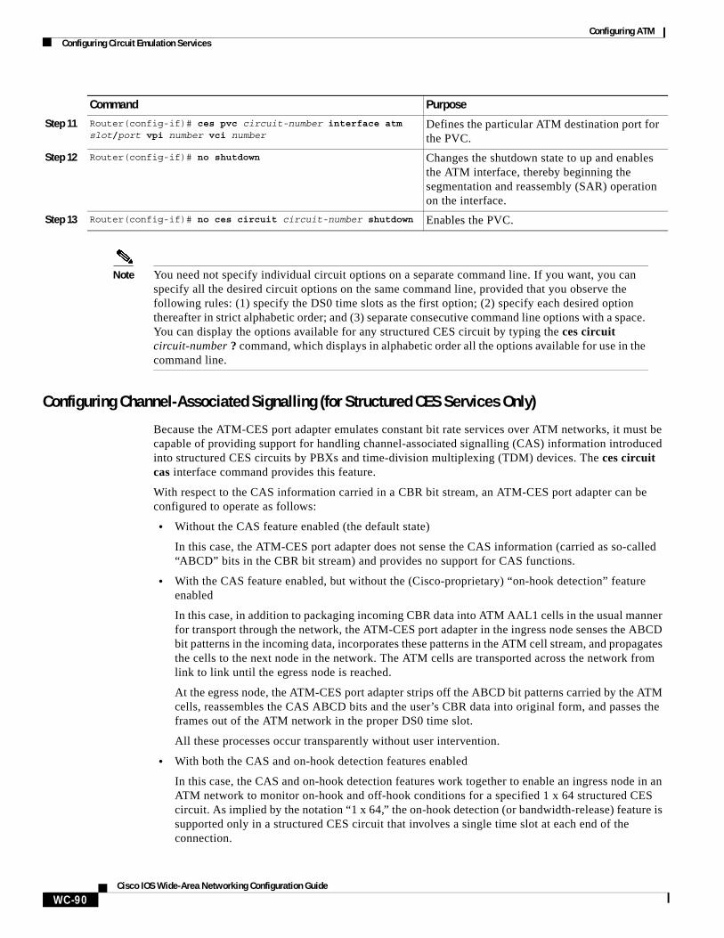
Configuring ATMConfiguring Circuit Emulation Services
WC-90Cisco IOS Wide-Area Networking Configuration Guide
Note You need not specify individual circuit options on a separate command line. If you want, you can specify all the desired circuit options on the same command line, provided that you observe the following rules: (1) specify the DS0 time slots as the first option; (2) specify each desired option thereafter in strict alphabetic order; and (3) separate consecutive command line options with a space. You can display the options available for any structured CES circuit by typing the ces circuit circuit-number ? command, which displays in alphabetic order all the options available for use in the command line.
Configuring Channel-Associated Signalling (for Structured CES Services Only)
Because the ATM-CES port adapter emulates constant bit rate services over ATM networks, it must be capable of providing support for handling channel-associated signalling (CAS) information introduced into structured CES circuits by PBXs and time-division multiplexing (TDM) devices. The ces circuit cas interface command provides this feature.
With respect to the CAS information carried in a CBR bit stream, an ATM-CES port adapter can be configured to operate as follows:
• Without the CAS feature enabled (the default state)
In this case, the ATM-CES port adapter does not sense the CAS information (carried as so-called “ABCD” bits in the CBR bit stream) and provides no support for CAS functions.
• With the CAS feature enabled, but without the (Cisco-proprietary) “on-hook detection” feature enabled
In this case, in addition to packaging incoming CBR data into ATM AAL1 cells in the usual manner for transport through the network, the ATM-CES port adapter in the ingress node senses the ABCD bit patterns in the incoming data, incorporates these patterns in the ATM cell stream, and propagates the cells to the next node in the network. The ATM cells are transported across the network from link to link until the egress node is reached.
At the egress node, the ATM-CES port adapter strips off the ABCD bit patterns carried by the ATM cells, reassembles the CAS ABCD bits and the user’s CBR data into original form, and passes the frames out of the ATM network in the proper DS0 time slot.
All these processes occur transparently without user intervention.
• With both the CAS and on-hook detection features enabled
In this case, the CAS and on-hook detection features work together to enable an ingress node in an ATM network to monitor on-hook and off-hook conditions for a specified 1 x 64 structured CES circuit. As implied by the notation “1 x 64,” the on-hook detection (or bandwidth-release) feature is supported only in a structured CES circuit that involves a single time slot at each end of the connection.
Step 11 Router(config-if)# ces pvc circuit-number interface atm slot/port vpi number vci number
Defines the particular ATM destination port for the PVC.
Step 12 Router(config-if)# no shutdown Changes the shutdown state to up and enables the ATM interface, thereby beginning the segmentation and reassembly (SAR) operation on the interface.
Step 13 Router(config-if)# no ces circuit circuit-number shutdown Enables the PVC.
Command Purpose
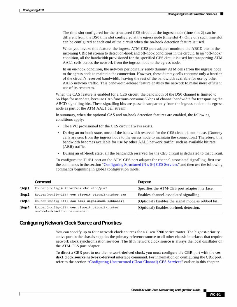
Configuring ATMConfiguring Circuit Emulation Services
WC-91Cisco IOS Wide-Area Networking Configuration Guide
The time slot configured for the structured CES circuit at the ingress node (time slot 2) can be different from the DS0 time slot configured at the egress node (time slot 4). Only one such time slot can be configured at each end of the circuit when the on-hook detection feature is used.
When you invoke this feature, the ingress ATM-CES port adapter monitors the ABCD bits in the incoming CBR bit stream to detect on-hook and off-hook conditions in the circuit. In an “off-hook” condition, all the bandwidth provisioned for the specified CES circuit is used for transporting ATM AAL1 cells across the network from the ingress node to the egress node.
In an on-hook condition, the network periodically sends dummy ATM cells from the ingress node to the egress node to maintain the connection. However, these dummy cells consume only a fraction of the circuit’s reserved bandwidth, leaving the rest of the bandwidth available for use by other AAL5 network traffic. This bandwidth-release feature enables the network to make more efficient use of its resources.
When the CAS feature is enabled for a CES circuit, the bandwidth of the DS0 channel is limited to 56 kbps for user data, because CAS functions consume 8 kbps of channel bandwidth for transporting the ABCD signalling bits. These signalling bits are passed transparently from the ingress node to the egress node as part of the ATM AAL1 cell stream.
In summary, when the optional CAS and on-hook detection features are enabled, the following conditions apply:
• The PVC provisioned for the CES circuit always exists.
• During an on-hook state, most of the bandwidth reserved for the CES circuit is not in use. (Dummy cells are sent from the ingress node to the egress node to maintain the connection.) Therefore, this bandwidth becomes available for use by other AAL5 network traffic, such as available bit rate (ABR) traffic.
• During an off-hook state, all the bandwidth reserved for the CES circuit is dedicated to that circuit.
To configure the T1/E1 port on the ATM-CES port adapter for channel-associated signalling, first use the commands in the section “Configuring Structured (N x 64) CES Services” and then use the following commands beginning in global configuration mode:
Configuring Network Clock Source and Priorities
You can specify up to four network clock sources for a Cisco 7200 series router. The highest-priority active port in the chassis supplies the primary reference source to all other chassis interfaces that require network clock synchronization services. The fifth network clock source is always the local oscillator on the ATM-CES port adapter.
To direct a CBR port to use the network-derived clock, you must configure the CBR port with the ces dsx1 clock source network-derived interface command. For information on configuring the CBR port, refer to the section “Configuring Unstructured (Clear Channel) CES Services” earlier in this chapter.
Command Purpose
Step 1 Router(config)# interface cbr slot/port Specifies the ATM-CES port adapter interface.
Step 2 Router(config-if)# ces circuit circuit-number cas Enables channel-associated signalling.
Step 3 Router(config-if)# ces dsx1 signalmode robbedbit (Optional) Enables the signal mode as robbed bit.
Step 4 Router(config-if)# ces circuit circuit-number on-hook-detection hex-number
(Optional) Enables on-hook detection.
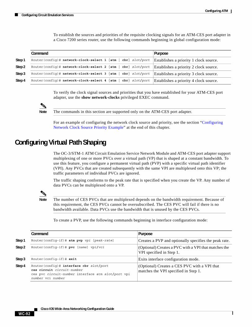
Configuring ATMConfiguring Circuit Emulation Services
WC-92Cisco IOS Wide-Area Networking Configuration Guide
To establish the sources and priorities of the requisite clocking signals for an ATM-CES port adapter in a Cisco 7200 series router, use the following commands beginning in global configuration mode:
To verify the clock signal sources and priorities that you have established for your ATM-CES port adapter, use the show network-clocks privileged EXEC command.
Note The commands in this section are supported only on the ATM-CES port adapter.
For an example of configuring the network clock source and priority, see the section “Configuring Network Clock Source Priority Example” at the end of this chapter.
Configuring Virtual Path ShapingThe OC-3/STM-1 ATM Circuit Emulation Service Network Module and ATM-CES port adapter support multiplexing of one or more PVCs over a virtual path (VP) that is shaped at a constant bandwidth. To use this feature, you configure a permanent virtual path (PVP) with a specific virtual path identifier (VPI). Any PVCs that are created subsequently with the same VPI are multiplexed onto this VP; the traffic parameters of individual PVCs are ignored.
The traffic shaping conforms to the peak rate that is specified when you create the VP. Any number of data PVCs can be multiplexed onto a VP.
Note The number of CES PVCs that are multiplexed depends on the bandwidth requirement. Because of this requirement, the CES PVCs cannot be oversubscribed. The CES PVC will fail if there is no bandwidth available. Data PVCs use the bandwidth that is unused by the CES PVCs.
To create a PVP, use the following commands beginning in interface configuration mode:
Command Purpose
Step 1 Router(config)# network-clock-select 1 {atm | cbr} slot/port Establishes a priority 1 clock source.
Step 2 Router(config)# network-clock-select 2 {atm | cbr} slot/port Establishes a priority 2 clock source.
Step 3 Router(config)# network-clock-select 3 {atm | cbr} slot/port Establishes a priority 3 clock source.
Step 4 Router(config)# network-clock-select 4 {atm | cbr} slot/port Establishes a priority 4 clock source.
Command Purpose
Step 1 Router(config-if)# atm pvp vpi [peak-rate] Creates a PVP and optionally specifies the peak rate.
Step 2 Router(config-if)# pvc [name] vpi/vci (Optional) Creates a PVC with a VPI that matches the VPI specified in Step 1.
Step 3 Router(config-if)# exit Exits interface configuration mode.
Step 4 Router(config)# interface cbr slot/portces circuit circuit-numberces pvc circuit-number interface atm slot/port vpi number vci number
(Optional) Creates a CES PVC with a VPI that matches the VPI specified in Step 1.
Configuring ATMConfiguring ATM Access over a Serial Interface
WC-93Cisco IOS Wide-Area Networking Configuration Guide
The value of the vpi argument is the virtual path identifier to be associated with the PVP (valid values are in the range 0 to 255 inclusive). The peak-rate argument is the maximum rate (in kbps) at which the PVP is allowed to transmit data. Valid values are in the range 84 kbps to line rate. The default peak rate is the line rate.
When you create a PVP, two PVCs are created (with VCI 3 and 4) by default. These PVCs are created for VP end-to-end loopback and segment loopback OAM support.
The pvc command is rejected if a non-multiplexed PVC with the specified VPI value already exists. This could happen if you first create a PVC with a given VPI value and then you subsequently enter this command.
To display information about the PVP, use the show atm vp EXEC command.
Note If you change the peak rate online, the ATM port will go down and then back up.
For an example of virtual path shaping, see the section “Configuring Virtual Path Shaping Example” at the end of this chapter.
Configuring ATM Access over a Serial InterfaceThis section describes how to configure routers that use a serial interface for ATM access through an ATM data service unit (ADSU). The configuration tasks include the steps necessary to enable Asynchronous Transfer Mode-Data Exchange Interface (ATM-DXI) encapsulation, select a multiprotocol encapsulation method using ATM-DXI, and set up a PVC for the selected encapsulation.
In routers with a serial interface, an ADSU is required to provide the ATM interface to the network, convert outgoing packets into ATM cells, and reassemble incoming ATM cells into packets.
Any serial interface can be configured for multiprotocol encapsulation over ATM-DXI, as specified by RFC 1483. At the ADSU, the DXI header is stripped off, and the protocol data is segmented into cells for transport over the ATM network.
RFC 1483 describes two methods of transporting multiprotocol connectionless network interconnect traffic over an ATM network. One method allows multiplexing of multiple protocols over a single PVC. The other method uses different virtual circuits to carry different protocols. Cisco’s implementation of RFC 1483 supports both methods and supports transport of Apollo Domain, AppleTalk, Banyan VINES, DECnet, IP, Novell IPX, ISO CLNS, and XNS traffic.
To configure ATM access over a serial interface, complete the tasks in the following sections. The first four tasks are required.
• Enabling the Serial Interface (Required)
• Enabling ATM-DXI Encapsulation (Required)
• Setting Up the ATM-DXI PVC (Required)
• Mapping Protocol Addresses to the ATM-DXI PVC (Required)
• Monitoring and Maintaining the ATM-DXI Serial Interface (Optional)
For an example of configuring ATM access over a serial interface, see the section “ATM Access over a Serial Interface Example” at the end of this chapter.
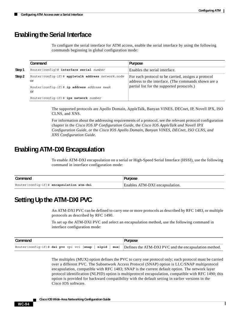
Configuring ATMConfiguring ATM Access over a Serial Interface
WC-94Cisco IOS Wide-Area Networking Configuration Guide
Enabling the Serial InterfaceTo configure the serial interface for ATM access, enable the serial interface by using the following commands beginning in global configuration mode:
The supported protocols are Apollo Domain, AppleTalk, Banyan VINES, DECnet, IP, Novell IPX, ISO CLNS, and XNS.
For information about the addressing requirements of a protocol, see the relevant protocol configuration chapter in the Cisco IOS IP Configuration Guide, the Cisco IOS AppleTalk and Novell IPX Configuration Guide, or the Cisco IOS Apollo Domain, Banyan VINES, DECnet, ISO CLNS, and XNS Configuration Guide.
Enabling ATM-DXI EncapsulationTo enable ATM-DXI encapsulation on a serial or High-Speed Serial Interface (HSSI), use the following command in interface configuration mode:
Setting Up the ATM-DXI PVCAn ATM-DXI PVC can be defined to carry one or more protocols as described by RFC 1483, or multiple protocols as described by RFC 1490.
To set up the ATM-DXI PVC and select an encapsulation method, use the following command in interface configuration mode:
The multiplex (MUX) option defines the PVC to carry one protocol only; each protocol must be carried over a different PVC. The Subnetwork Access Protocol (SNAP) option is LLC/SNAP multiprotocol encapsulation, compatible with RFC 1483; SNAP is the current default option. The network layer protocol identification (NLPID) option is multiprotocol encapsulation, compatible with RFC 1490; this option is provided for backward compatibility with the default setting in earlier versions in the Cisco IOS software.
Command Purpose
Step 1 Router(config)# interface serial number Enables the serial interface.
Step 2 Router(config-if)# appletalk address network.node
or
Router(config-if)# ip address address mask
or
Router(config-if)# ipx network number
For each protocol to be carried, assigns a protocol address to the interface. (The commands shown are a partial list for the supported protocols.)
Command Purpose
Router(config-if)# encapsulation atm-dxi Enables ATM-DXI encapsulation.
Command PurposeRouter(config-if)# dxi pvc vpi vci [snap | nlpid | mux] Defines the ATM-DXI PVC and the encapsulation method.
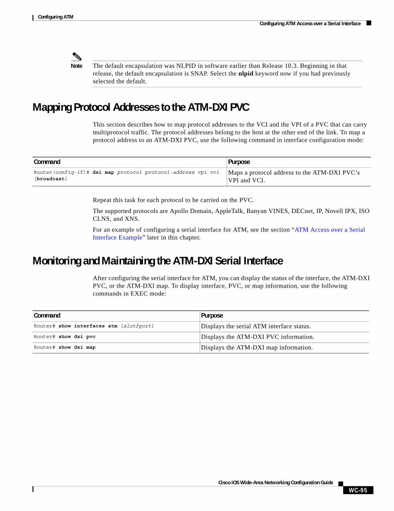
Configuring ATMConfiguring ATM Access over a Serial Interface
WC-95Cisco IOS Wide-Area Networking Configuration Guide
Note The default encapsulation was NLPID in software earlier than Release 10.3. Beginning in that release, the default encapsulation is SNAP. Select the nlpid keyword now if you had previously selected the default.
Mapping Protocol Addresses to the ATM-DXI PVCThis section describes how to map protocol addresses to the VCI and the VPI of a PVC that can carry multiprotocol traffic. The protocol addresses belong to the host at the other end of the link. To map a protocol address to an ATM-DXI PVC, use the following command in interface configuration mode:
Repeat this task for each protocol to be carried on the PVC.
The supported protocols are Apollo Domain, AppleTalk, Banyan VINES, DECnet, IP, Novell IPX, ISO CLNS, and XNS.
For an example of configuring a serial interface for ATM, see the section “ATM Access over a Serial Interface Example” later in this chapter.
Monitoring and Maintaining the ATM-DXI Serial InterfaceAfter configuring the serial interface for ATM, you can display the status of the interface, the ATM-DXI PVC, or the ATM-DXI map. To display interface, PVC, or map information, use the following commands in EXEC mode:
Command Purpose
Router(config-if)# dxi map protocol protocol-address vpi vci [broadcast]
Maps a protocol address to the ATM-DXI PVC’s VPI and VCI.
Command Purpose
Router# show interfaces atm [slot/port] Displays the serial ATM interface status.
Router# show dxi pvc Displays the ATM-DXI PVC information.
Router# show dxi map Displays the ATM-DXI map information.
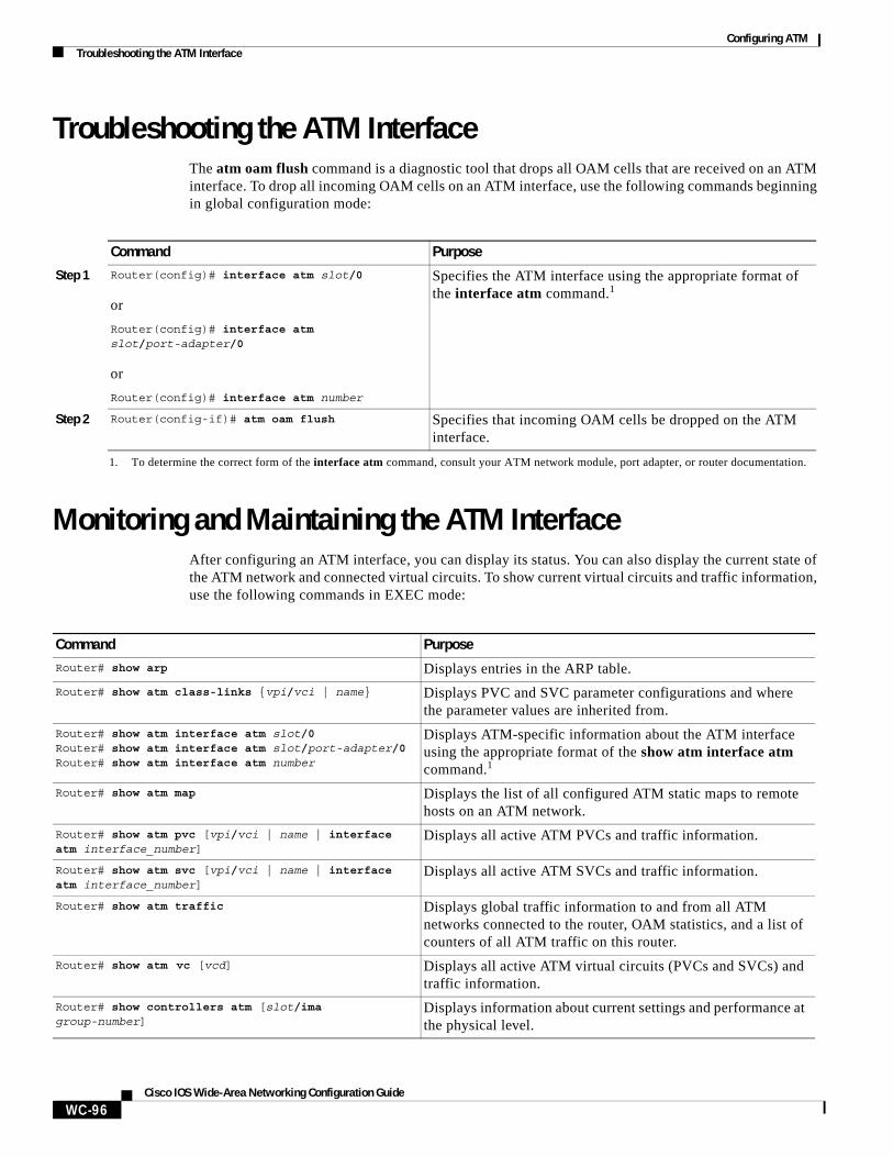
Configuring ATMTroubleshooting the ATM Interface
WC-96Cisco IOS Wide-Area Networking Configuration Guide
Troubleshooting the ATM InterfaceThe atm oam flush command is a diagnostic tool that drops all OAM cells that are received on an ATM interface. To drop all incoming OAM cells on an ATM interface, use the following commands beginning in global configuration mode:
Monitoring and Maintaining the ATM InterfaceAfter configuring an ATM interface, you can display its status. You can also display the current state of the ATM network and connected virtual circuits. To show current virtual circuits and traffic information, use the following commands in EXEC mode:
Command Purpose
Step 1 Router(config)# interface atm slot/0
or
Router(config)# interface atm slot/port-adapter/0
or
Router(config)# interface atm number
Specifies the ATM interface using the appropriate format of the interface atm command.1
1. To determine the correct form of the interface atm command, consult your ATM network module, port adapter, or router documentation.
Step 2 Router(config-if)# atm oam flush Specifies that incoming OAM cells be dropped on the ATM interface.
Command Purpose
Router# show arp Displays entries in the ARP table.
Router# show atm class-links {vpi/vci | name} Displays PVC and SVC parameter configurations and where the parameter values are inherited from.
Router# show atm interface atm slot/0Router# show atm interface atm slot/port-adapter/0Router# show atm interface atm number
Displays ATM-specific information about the ATM interface using the appropriate format of the show atm interface atm command.1
Router# show atm map Displays the list of all configured ATM static maps to remote hosts on an ATM network.
Router# show atm pvc [vpi/vci | name | interface atm interface_number]
Displays all active ATM PVCs and traffic information.
Router# show atm svc [vpi/vci | name | interface atm interface_number]
Displays all active ATM SVCs and traffic information.
Router# show atm traffic Displays global traffic information to and from all ATM networks connected to the router, OAM statistics, and a list of counters of all ATM traffic on this router.
Router# show atm vc [vcd] Displays all active ATM virtual circuits (PVCs and SVCs) and traffic information.
Router# show controllers atm [slot/ima group-number]
Displays information about current settings and performance at the physical level.
Configuring ATMATM Configuration Examples
WC-97Cisco IOS Wide-Area Networking Configuration Guide
ATM Configuration ExamplesThe examples in the following sections illustrate how to configure ATM for the features described in this chapter. The examples below are presented in the same order as the corresponding configuration task sections presented earlier in this chapter:
• Creating a PVC Example
• PVC with AAL5 and LLC/SNAP Encapsulation Examples
• PVCs in a Fully Meshed Network Example
• Configuring an ABR PVC Example
• Configuring PVC Discovery Example
• Enabling Inverse ARP Example
• Configuring Generation of End-to-End F5 OAM Loopback Cells Example
• Configuring PVC Trap Support Example
• Configuring Communication with the ILMI Example
• SVCs in a Fully Meshed Network Example
• ATM ESI Address Example
• ATM NSAP Address Example
• SVCs with Multipoint Signalling Example
• Configuring SVC Traffic Parameters Example
• Creating a VC Class Examples
• Applying a VC Class Examples
• ILMI Management on an ATM PVC Example
• OAM Management on an ATM PVC Example
• OAM Management on an ATM SVC Example
• Classical IP and ARP Examples
• Dynamic Rate Queue Examples
• PVC with AAL3/4 and SMDS Encapsulation Examples
• Transparent Bridging on an AAL5-SNAP PVC Example
• Inverse Multiplexing over ATM Examples
Router# show ima interface atm [slot]/ima [group-number] [detail]
Displays general or detailed information about IMA groups and the links in those groups.
Router# show interfaces atmRouter# show interfaces atm slot/0Router# show interfaces atm slot/port-adapter/0
Displays statistics for the ATM interface using the appropriate format of the show interfaces atm command.
Router# show network-clocks Displays the clock signal sources and priorities that you established on the router.
Router# show sscop Displays SSCOP details for the ATM interface.
1. To determine the correct form of the interface atm command, consult your ATM network module, port adapter, or router documentation.
Command Purpose
Configuring ATMATM Configuration Examples
WC-98Cisco IOS Wide-Area Networking Configuration Guide
• Configuring ATM E.164 Auto Conversion Example
• Circuit Emulation Service Examples
• ATM Access over a Serial Interface Example
• ATM Port Adapters Connected Back-to-Back Example
Creating a PVC ExampleThe following example shows how to create a PVC on an ATM main interface with AAL5/MUX encapsulation configured and a VBR-NRT QOS specified. For further information, refer to the sections “Creating a PVC” and “Configuring PVC Traffic Parameters” earlier in this chapter.
interface 2/0pvc cisco 1/40encapsulation aal5mux ipvbr-nrt 100000 50000 20exit
PVC with AAL5 and LLC/SNAP Encapsulation ExamplesThe following example shows how to create a PVC 0/50 on ATM interface 3/0. It uses the global default LLC/SNAP encapsulation over AAL5. The interface is at IP address 1.1.1.1 with 1.1.1.5 at the other end of the connection. For further information, refer to the sections “Creating a PVC” and “Mapping a Protocol Address to a PVC” earlier in this chapter.
interface atm 3/0ip address 1.1.1.1 255.255.255.0pvc 0/50protocol ip 1.1.1.5 broadcastexit
!ip route-cache cbus
The following example is a typical ATM configuration for a PVC:
interface atm 4/0ip address 172.21.168.112 255.255.255.0atm maxvc 512pvc 1/51protocol ip 171.21.168.110exit
!pvc 2/52protocol decnet 10.1 broadcastexit
!pvc 3/53protocol clns 47.004.001.0000.0c00.6e26.00 broadcastexit
!decnet cost 1clns router iso-igrp cometexit
!router iso-igrp cometnet 47.0004.0001.0000.0c00.6666.00exit
!
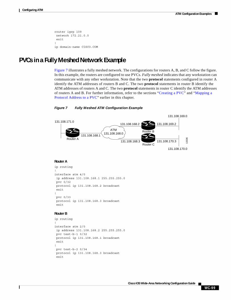
Configuring ATMATM Configuration Examples
WC-99Cisco IOS Wide-Area Networking Configuration Guide
router igrp 109network 172.21.0.0exit
!ip domain-name CISCO.COM
PVCs in a Fully Meshed Network ExampleFigure 7 illustrates a fully meshed network. The configurations for routers A, B, and C follow the figure. In this example, the routers are configured to use PVCs. Fully meshed indicates that any workstation can communicate with any other workstation. Note that the two protocol statements configured in router A identify the ATM addresses of routers B and C. The two protocol statements in router B identify the ATM addresses of routers A and C. The two protocol statements in router C identify the ATM addresses of routers A and B. For further information, refer to the sections “Creating a PVC” and “Mapping a Protocol Address to a PVC” earlier in this chapter.
Figure 7 Fully Meshed ATM Configuration Example
Router Aip routing!interface atm 4/0ip address 131.108.168.1 255.255.255.0pvc 0/32protocol ip 131.108.168.2 broadcastexit
!pvc 0/33protocol ip 131.108.168.3 broadcastexit
Router Bip routing!interface atm 2/0ip address 131.108.168.2 255.255.255.0pvc test-b-1 0/32protocol ip 131.108.168.1 broadcastexit
!pvc test-b-2 0/34protocol ip 131.108.168.3 broadcastexit
Router A
1333
6
Router B
Router C
ATM131.108.168.0
131.108.168.1
131.108.171.0131.108.168.2
131.108.168.3
131.108.169.0
131.108.169.2
131.108.170.3
131.108.170.0
Configuring ATMATM Configuration Examples
WC-100Cisco IOS Wide-Area Networking Configuration Guide
Router Cip routing!interface atm 4/0ip address 131.108.168.3 255.255.255.0pvc 0/33 protocol ip 131.108.168.1 broadcastexit
!pvc 0/34protocol ip 131.108.168.2 broadcastexit
Configuring an ABR PVC ExampleThe following example shows a typical ABR PVC configuration for the ATM-CES port adapter on a Cisco 7200 series router. In this example, the default peak cell rate and minimum cell rate is used (default PCR is the line rate and MCR is 0), and the ABR rate increase and decrease factor is set to 32. For further information, refer to the section “Configuring PVC Traffic Parameters” earlier in this chapter.
interface atm 4/0ip address 1.1.1.1 255.255.255.0pvc 0/34atm abr rate-factor 32 32no shutdownexit
Configuring PVC Discovery ExampleThe following example shows how to enable PVC Discovery on an ATM main interface 2/0. The keyword subinterface is used so that all discovered PVCs with a VPI value of 1 will be assigned to the subinterface 2/0.1. For further information, refer to the section “Configuring PVC Discovery” earlier in this chapter.
interface atm 2/0pvc RouterA 0/16 ilmiexitatm ilmi-pvc-discovery subinterfaceexit
!interface atm 2/0.1 multipointip address 172.21.51.5 255.255.255.0
Enabling Inverse ARP ExampleThe following example shows how to enable Inverse ARP on an ATM interface and specifies an Inverse ARP time period of 10 minutes. For further information, refer to the section “Enabling Inverse ARP” earlier in this chapter.
interface atm 2/0pvc 1/32inarp 10exit
Configuring ATMATM Configuration Examples
WC-101Cisco IOS Wide-Area Networking Configuration Guide
Configuring Generation of End-to-End F5 OAM Loopback Cells ExampleThe following example shows how to enable OAM management on an ATM PVC. The PVC is assigned the name routerA and the VPI and VCI are 0 and 32, respectively. OAM management is enabled with a frequency of 3 seconds between OAM cell transmissions. For further information, refer to the section “Configuring Generation of End-to-End F5 OAM Loopback Cells to Verify Connectivity” earlier in this chapter.
interface atm 2/0pvc routerA 0/32oam-pvc manage 3oam retry 5 5 10
Configuring PVC Trap Support ExampleThe following example shows how to configure PVC trap support on your Cisco router:
!For PVC trap support to work on your router, you must first have SNMP support and !an IP routing protocol configured on your router:Router(config)# snmp-server community public roRouter(config)# snmp-server host 171.69.61.90 public Router(config)# ip routingRouter(config)# router igrp 109Router(config-router)# network 172.21.0.0!!Enable PVC trap support and OAM management:Router(config)# snmp-server enable traps atm pvc interval 40 fail-interval 10Router(config)# interface atm 1/0.1 Router(config-if)# pvc 0/1Router(config-if-atm-vc)# oam-pvc manage!! Now if PVC 0/1 goes down, host 171.69.61.90 will receive traps.
For further information, refer to the “Configuring PVC Trap Support” section earlier in this chapter.
Configuring Communication with the ILMI ExampleThe following example shows how to configure the ILMI protocol on an ATM main interface. For further information, refer to the section “Configuring Communication with the ILMI” earlier in this chapter.
interface 2/0pvc cisco 0/16 ilmiexit
SVCs in a Fully Meshed Network ExampleThe following example is also a configuration for the fully meshed network shown in Figure 7, but this example uses SVCs. PVC 0/5 is the signaling PVC.
Note Configuring explicit ATM NSAP addresses on the routers in this example also requires configuring static call routing on the ATM switch in order to route the calls properly. For more information on how to configure static call routing, refer to your switch documentation.
Configuring ATMATM Configuration Examples
WC-102Cisco IOS Wide-Area Networking Configuration Guide
For further information, see the following sections earlier in this chapter:
• Configuring the PVC That Performs SVC Call Setup
• Configuring the NSAP Address
• Creating an SVC
Router Ainterface atm 4/0ip address 172.16.168.1 255.255.255.0atm nsap-address AB.CDEF.01.234567.890A.BCDE.F012.3456.7890.1234.12atm maxvc 1024pvc 0/5 qsaalexit
!svc svc-1 nsap BC.CDEF.01.234567.890A.BCDE.F012.3456.7890.1334.13protocol ip 172.16.168.2exit
!svc svc-2 nsap CA.CDEF.01.234567.890A.BCDE.F012.3456.7890.1334.12protocol ip 131.108.168.3exit
Router Binterface atm 2/0ip address 172.16.168.2 255.255.255.0atm nsap-address BC.CDEF.01.234567.890A.BCDE.F012.3456.7890.1334.13atm maxvc 1024pvc 0/5 qsaalexit
!svc svc-1 nsap AB.CDEF.01.234567.890A.BCDE.F012.3456.7890.1234.12protocol ip 172.16.168.1exit
!svc svc-2 nsap CA.CDEF.01.234567.890A.BCDE.F012.3456.7890.1334.12protocol ip 172.16.168.3exit
Router Cinterface atm 4/0 ip address 172.16.168.3 255.255.255.0 atm nsap-address CA.CDEF.01.234567.890A.BCDE.F012.3456.7890.1334.12 atm maxvc 1024 pvc 0/5 qsaal exit ! svc nsap AB.CDEF.01.234567.890A.BCDE.F012.3456.7890.1234.12 protocol ip 172.16.168.1 exit ! svc nsap BC.CDEF.01.234567.890A.BCDE.F012.3456.7890.1334.13 protocol ip 172.16.168.2 exit
Configuring ATMATM Configuration Examples
WC-103Cisco IOS Wide-Area Networking Configuration Guide
ATM ESI Address ExampleThe following example shows how to set up the ILMI PVC and how to assign the ESI and selector field values on a Cisco 7500 series router. For further information, refer to the section “Configuring the ESI and Selector Fields” earlier in this chapter.
interface atm 4/0pvc 0/16 ilmiatm esi-address 345678901234.12
ATM NSAP Address ExampleThe following example shows how to assign NSAP address AB.CDEF.01.234567.890A.BCDE.F012.3456.7890.1234.12 to ATM interface 4/0. For further information, refer to the section “Configuring the Complete NSAP Address” earlier in this chapter.
interface atm 4/0atm nsap-address AB.CDEF.01.234567.890A.BCDE.F012.3456.7890.1234.12
You can display the ATM address for the interface by executing the show interface atm command.
SVCs with Multipoint Signalling ExampleThe following example shows how to configure an ATM interface for SVCs using multipoint signalling. For further information, refer to the section “Configuring Point-to-Multipoint Signalling” earlier in this chapter.
interface atm 2/0ip address 4.4.4.6 255.255.255.0pvc 0/5 qsaalexit
!pvc 0/16 ilmiexit
!atm esi-address 3456.7890.1234.12
!svc mcast-1 nsap cd.cdef.01.234566.890a.bcde.f012.3456.7890.1234.12 broadcastprotocol ip 4.4.4.4 broadcastexit
!svc mcast-2 nsap 31.3233.34.352637.3839.3031.3233.3435.3637.3839.30 broadcastprotocol ip 4.4.4.7 broadcastexit
!atm multipoint-signallingatm maxvc 1024
Configuring SVC Traffic Parameters ExampleFigure 8 illustrates a source and destination router implementing traffic settings that correspond end-to-end. The output values for the source router correspond to the input values for the destination router. The following example shows how to specify VBR-NRT traffic parameters on the source router. For further information, refer to the section “Configuring SVC Traffic Parameters” earlier in this chapter.
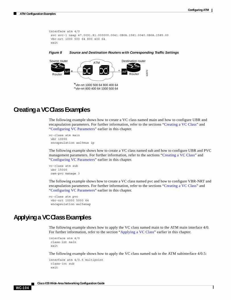
Configuring ATMATM Configuration Examples
WC-104Cisco IOS Wide-Area Networking Configuration Guide
interface atm 4/0svc svc-1 nsap 47.0091.81.000000.0041.0B0A.1581.0040.0B0A.1585.00vbr-nrt 1000 500 64 800 400 64exit
Figure 8 Source and Destination Routers with Corresponding Traffic Settings
Creating a VC Class ExamplesThe following example shows how to create a VC class named main and how to configure UBR and encapsulation parameters. For further information, refer to the sections “Creating a VC Class” and “Configuring VC Parameters” earlier in this chapter.
vc-class atm mainubr 10000encapsulation aal5mux ip
The following example shows how to create a VC class named sub and how to configure UBR and PVC management parameters. For further information, refer to the sections “Creating a VC Class” and “Configuring VC Parameters” earlier in this chapter.
vc-class atm sububr 15000oam-pvc manage 3
The following example shows how to create a VC class named pvc and how to configure VBR-NRT and encapsulation parameters. For further information, refer to the sections “Creating a VC Class” and “Configuring VC Parameters” earlier in this chapter.
vc-class atm pvcvbr-nrt 10000 5000 64encapsulation aal5snap
Applying a VC Class ExamplesThe following example shows how to apply the VC class named main to the ATM main interface 4/0. For further information, refer to the section “Applying a VC Class” earlier in this chapter.
interface atm 4/0class-int mainexit
The following example shows how to apply the VC class named sub to the ATM subinterface 4/0.5:
interface atm 4/0.5 multipointclass-int subexit
ATM
6287
0
Router RouterAIPAIP
Source router Destination router
* +
*vbr-nrt 1000 500 64 800 400 64+vbr-nrt 800 400 64 1000 500 64
Configuring ATMATM Configuration Examples
WC-105Cisco IOS Wide-Area Networking Configuration Guide
The following example shows how to apply the VC class named pvc directly on the PVC 0/56:
interface atm 4/0.5 multipointpvc 0/56class-vc pvcexit
ILMI Management on an ATM PVC ExampleThe following example first shows how to configure an ILMI PVC on the main ATM interface 0/0. ILMI management is then configured on the ATM subinterface 0/0.1. For further information, refer to the section “Configuring ILMI Management” earlier in this chapter.
interface atm 0/0pvc routerA 0/16 ilmiexit
!interface atm 0/0.1 multipointpvc 0/60ilmi manage
OAM Management on an ATM PVC ExampleThe following example shows how to enable OAM management on an ATM PVC. The PVC is assigned the name routerA and the VPI and VCI are 0 and 32, respectively. OAM management is enabled with a frequency of 3 seconds between OAM cell transmissions. For further information, refer to the section “Configuring OAM Management for PVCs” earlier in this chapter.
interface atm 2/0pvc routerA 0/32oam-pvc manage 3oam retry 5 5 10
OAM Management on an ATM SVC ExampleThe following example shows how to enable OAM management on an ATM SVC. The SVC is assigned the name routerZ and the destination NSAP address is specified. OAM management is enabled with a frequency of 3 seconds between OAM cell transmissions. For further information, refer to the section “Configuring OAM Management for SVCs” earlier in this chapter.
interface atm 1/0svc routerZ nsap 47.0091.81.000000.0040.0B0A.2501.ABC1.3333.3333.05oam-svc manage 3oam retry 5 5 10
Classical IP and ARP ExamplesThis section provides three examples of classical IP and ARP configuration, one each for a client and a server in an SVC environment, and one for ATM Inverse ARP in a PVC environment.
Configuring ATMATM Configuration Examples
WC-106Cisco IOS Wide-Area Networking Configuration Guide
Configuring ATM ARP Client in an SVC Environment Example
This example shows how to configure an ATM ARP client in an SVC environment. Note that the client in this example and the ATM ARP server in the next example are configured to be on the same IP network. For further information, refer to the section “Configuring the Router as an ATM ARP Client” earlier in this chapter.
interface atm 2/0.5atm nsap-address ac.2456.78.040000.0000.0000.0000.0000.0000.0000.00ip address 10.0.0.2 255.0.0.0pvc 0/5 qsaalatm arp-server nsap ac.1533.66.020000.0000.0000.0000.0000.0000.0000.00
Configuring ATM ARP Server in an SVC Environment Example
The following example shows how to configure ATM on an interface and configures the interface to function as the ATM ARP server for the IP subnetwork. For further information, refer to the section “Configuring the Router as an ATM ARP Server” earlier in this chapter.
interface atm 0/0ip address 10.0.0.1 255.0.0.0atm nsap-address ac.1533.66.020000.0000.0000.0000.0000.0000.0000.00atm rate-queue 1 100atm maxvc 1024pvc 0/5 qsaalatm arp-server self
Configuring ATM Inverse ARP in a PVC Environment Example
The following example shows how to configure ATM on an interface and then configures the ATM Inverse ARP mechanism on the PVCs on the interface, with Inverse ARP datagrams sent every 5 minutes on three of the PVCs. The fourth PVC will not send Inverse ATM ARP datagrams, but will receive and respond to Inverse ATM ARP requests. For further information, refer to the section “Configuring Classical IP and ARP in an SVC Environment” earlier in this chapter.
interface atm 4/0ip address 172.21.1.111 255.255.255.0pvc 0/32inarp 5exit
!pvc 0/33inarp 5exit
!pvc 0/34inarp 5exit
!interface atm 4/0.1 point-to-pointpvc 0/35exit
No map-group and map-list commands are needed for IP.
Configuring ATMATM Configuration Examples
WC-107Cisco IOS Wide-Area Networking Configuration Guide
Dynamic Rate Queue ExamplesThe following examples assume that no permanent rate queues have been configured. The software dynamically creates rate queues when a pvc command creates a new PVC that does not match any user-configured rate queue. For further information, refer to the section “Using Dynamic Rate Queues” earlier in this chapter.
The following example shows how to set the peak rate to the maximum that the PLIM will allow. Then it creates a rate queue for the peak rate of this VC.
interface 2/0pvc 1/41exit
The following example shows how to create a 100-Mbps rate queue with an average rate of 50 Mbps and a burst size of 64 cells:
interface 2/0pvc 2/42vbr-nrt 100000 50000 64exit
The following example shows how to create a 15-Mbps rate queue and set the average rate to the peak rate:
interface 2/0pvc 3/43ubr 15000exit
The following example shows how to configure a rate queue tolerance on the ATM interface with slot 2 and port 0. A tolerance-value of 20 is specified, which will apply to SVCs, discovered VCs, and PVCs.
interface atm 2/0atm rate-queue tolerance svc pvc 20
PVC with AAL3/4 and SMDS Encapsulation ExamplesThe following example shows how to create a minimal configuration of an ATM interface to support AAL3/4 and SMDS encapsulation; no protocol configuration is shown. For further information, refer to the section “Configuring ATM Subinterfaces for SMDS Networks” earlier in this chapter.
interface atm 3/0atm aal aal3/4atm smds-address c140.888.9999atm vp-filter 0atm multicast e180.0999.9999atm pvc 30 0 30 aal34smds
The following example shows how IP dynamic routing might coexist with static routing of another protocol:
interface atm 3/0ip address 172.21.168.112 255.255.255.0atm aal aal3/4atm smds-address c140.888.9999atm multicast e180.0999.9999atm vp-filter 0atm pvc 30 0 30 aal34smdsmap-group atmappletalk address 10.1appletalk zone atm
Configuring ATMATM Configuration Examples
WC-108Cisco IOS Wide-Area Networking Configuration Guide
!map-group atm atalk 10.2 smds c140.8111.1111 broadcast
This example shows that IP configured is dynamically routed, but that AppleTalk is statically routed. An AppleTalk remote host is configured at address 10.2 and is associated with SMDS address c140.8111.1111.
AAL3/4 associates a protocol address with an SMDS address, as shown in the last line of this example. In contrast, AAL5 static maps associate a protocol address with a PVC number.
Transparent Bridging on an AAL5-SNAP PVC ExampleIn the following example, three AAL5-SNAP PVCs are created on the same ATM interface. The router will broadcast all spanning tree updates to these AAL5-SNAP PVCs. No other virtual circuits will receive spanning tree updates. For further information, refer to the section “Configuring Fast-Switched Transparent Bridging for SNAP PVCs” earlier in this chapter.
interface atm 4/0ip address 1.1.1.1 255.0.0.0pvc 1/33pvc 1/34pvc 1/35bridge-group 1
!bridge 1 protocol dec
Inverse Multiplexing over ATM ExamplesFor examples of inverse multiplexing over ATM (IMA) configuration, see the following sections:
• E1 IMA on Multiport T1/E1 ATM Network Module Example
• T1 IMA on Multiport T1/E1 ATM Network Module Example
• T1 IMA on Multiport T1/E1 ATM Port Adapter Example
E1 IMA on Multiport T1/E1 ATM Network Module Example
The following example shows the setup of ATM interfaces, IMA groups, PVCs, and SVCs for E1 IMA on a Multiport T1/E1 ATM Network Module:
version 12.0service timestamps debug uptimeservice timestamps log uptimeno service password-encryption!hostname IMARouter!logging buffered 4096 debugging!ip subnet-zerono ip domain-lookupip host 10.11.16.2ip host 10.11.16.3ip host 10.11.55.192ip host 10.11.55.193ip host 10.11.55.195
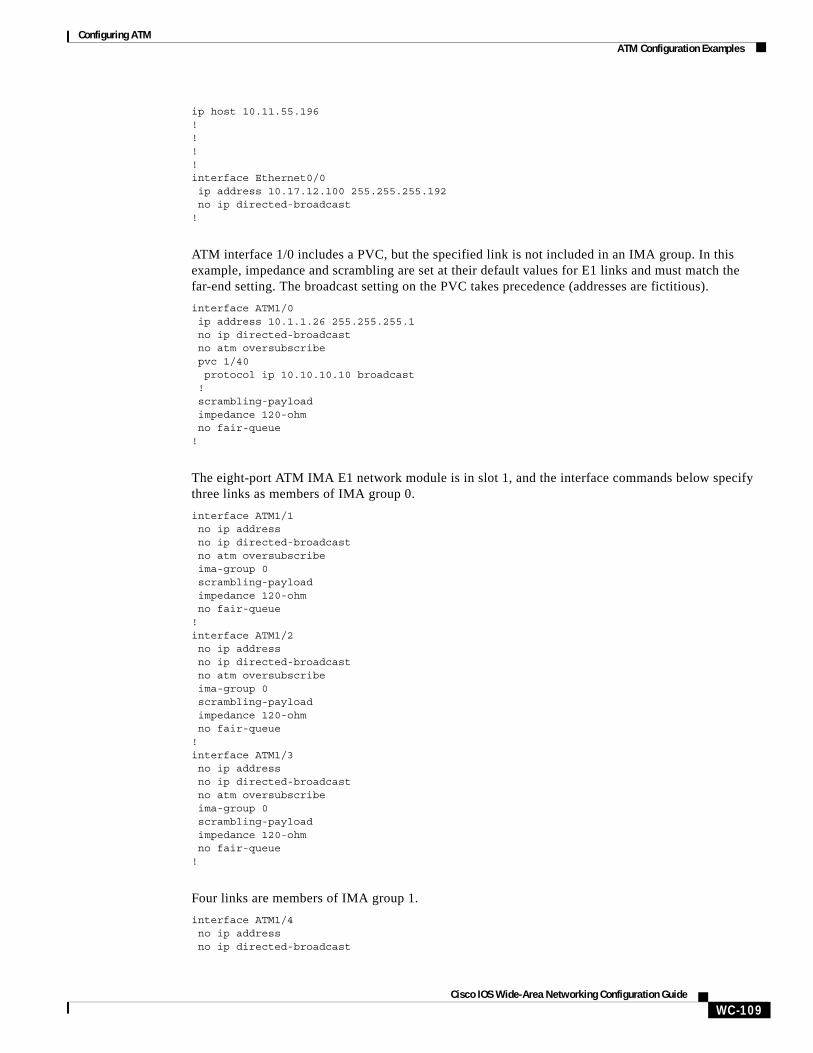
Configuring ATMATM Configuration Examples
WC-109Cisco IOS Wide-Area Networking Configuration Guide
ip host 10.11.55.196!!!!interface Ethernet0/0 ip address 10.17.12.100 255.255.255.192 no ip directed-broadcast!
ATM interface 1/0 includes a PVC, but the specified link is not included in an IMA group. In this example, impedance and scrambling are set at their default values for E1 links and must match the far-end setting. The broadcast setting on the PVC takes precedence (addresses are fictitious).
interface ATM1/0 ip address 10.1.1.26 255.255.255.1 no ip directed-broadcast no atm oversubscribe pvc 1/40 protocol ip 10.10.10.10 broadcast ! scrambling-payload impedance 120-ohm no fair-queue!
The eight-port ATM IMA E1 network module is in slot 1, and the interface commands below specify three links as members of IMA group 0.
interface ATM1/1 no ip address no ip directed-broadcast no atm oversubscribe ima-group 0 scrambling-payload impedance 120-ohm no fair-queue!interface ATM1/2 no ip address no ip directed-broadcast no atm oversubscribe ima-group 0 scrambling-payload impedance 120-ohm no fair-queue!interface ATM1/3 no ip address no ip directed-broadcast no atm oversubscribe ima-group 0 scrambling-payload impedance 120-ohm no fair-queue!
Four links are members of IMA group 1.
interface ATM1/4 no ip address no ip directed-broadcast
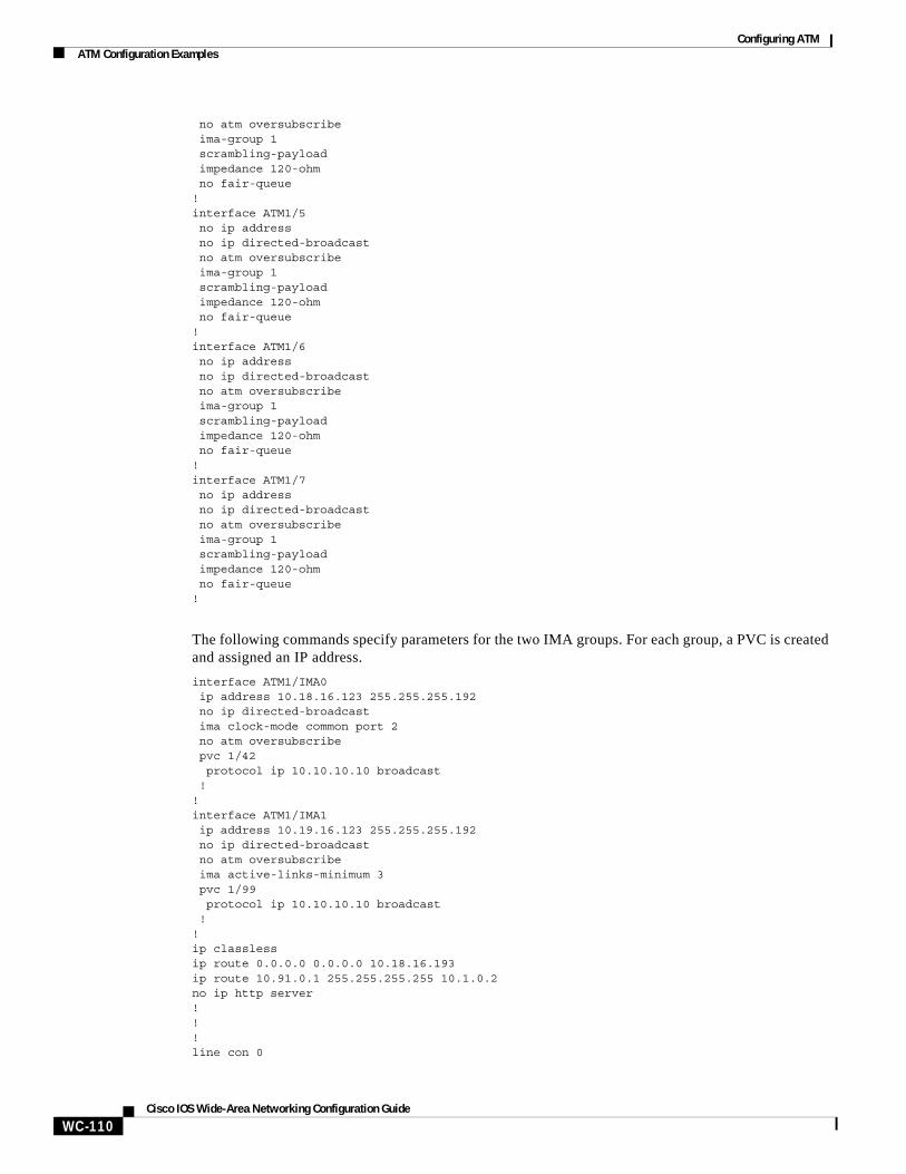
Configuring ATMATM Configuration Examples
WC-110Cisco IOS Wide-Area Networking Configuration Guide
no atm oversubscribe ima-group 1 scrambling-payload impedance 120-ohm no fair-queue!interface ATM1/5 no ip address no ip directed-broadcast no atm oversubscribe ima-group 1 scrambling-payload impedance 120-ohm no fair-queue!interface ATM1/6 no ip address no ip directed-broadcast no atm oversubscribe ima-group 1 scrambling-payload impedance 120-ohm no fair-queue!interface ATM1/7 no ip address no ip directed-broadcast no atm oversubscribe ima-group 1 scrambling-payload impedance 120-ohm no fair-queue!
The following commands specify parameters for the two IMA groups. For each group, a PVC is created and assigned an IP address.
interface ATM1/IMA0 ip address 10.18.16.123 255.255.255.192 no ip directed-broadcast ima clock-mode common port 2 no atm oversubscribe pvc 1/42 protocol ip 10.10.10.10 broadcast !!interface ATM1/IMA1 ip address 10.19.16.123 255.255.255.192 no ip directed-broadcast no atm oversubscribe ima active-links-minimum 3 pvc 1/99 protocol ip 10.10.10.10 broadcast !!ip classlessip route 0.0.0.0 0.0.0.0 10.18.16.193ip route 10.91.0.1 255.255.255.255 10.1.0.2no ip http server!!!line con 0
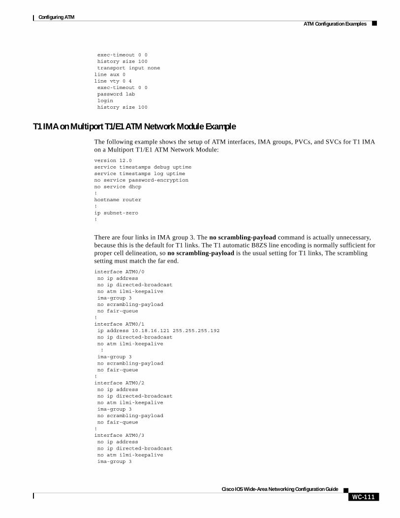
Configuring ATMATM Configuration Examples
WC-111Cisco IOS Wide-Area Networking Configuration Guide
exec-timeout 0 0 history size 100 transport input noneline aux 0line vty 0 4 exec-timeout 0 0 password lab login history size 100
T1 IMA on Multiport T1/E1 ATM Network Module Example
The following example shows the setup of ATM interfaces, IMA groups, PVCs, and SVCs for T1 IMA on a Multiport T1/E1 ATM Network Module:
version 12.0service timestamps debug uptimeservice timestamps log uptimeno service password-encryptionno service dhcp!hostname router!ip subnet-zero!
There are four links in IMA group 3. The no scrambling-payload command is actually unnecessary, because this is the default for T1 links. The T1 automatic B8ZS line encoding is normally sufficient for proper cell delineation, so no scrambling-payload is the usual setting for T1 links, The scrambling setting must match the far end.
interface ATM0/0 no ip address no ip directed-broadcast no atm ilmi-keepalive ima-group 3 no scrambling-payload no fair-queue!interface ATM0/1 ip address 10.18.16.121 255.255.255.192 no ip directed-broadcast no atm ilmi-keepalive ! ima-group 3 no scrambling-payload no fair-queue!interface ATM0/2 no ip address no ip directed-broadcast no atm ilmi-keepalive ima-group 3 no scrambling-payload no fair-queue!interface ATM0/3 no ip address no ip directed-broadcast no atm ilmi-keepalive ima-group 3
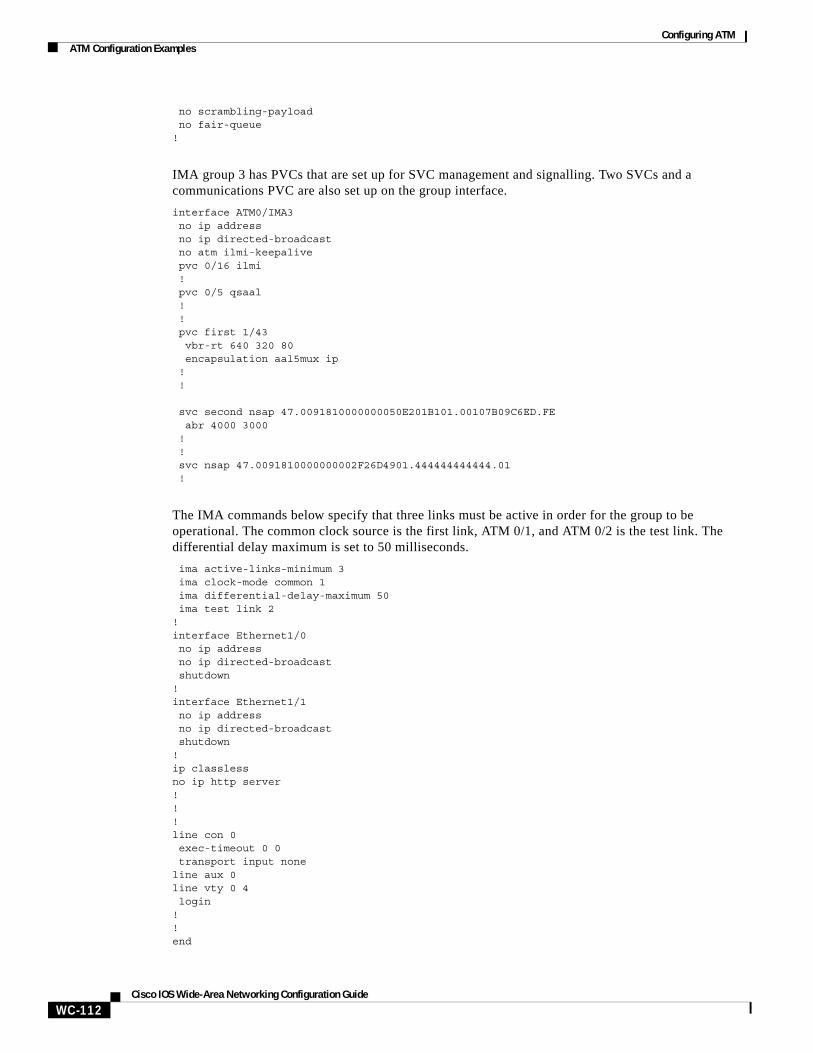
Configuring ATMATM Configuration Examples
WC-112Cisco IOS Wide-Area Networking Configuration Guide
no scrambling-payload no fair-queue!
IMA group 3 has PVCs that are set up for SVC management and signalling. Two SVCs and a communications PVC are also set up on the group interface.
interface ATM0/IMA3 no ip address no ip directed-broadcast no atm ilmi-keepalive pvc 0/16 ilmi ! pvc 0/5 qsaal ! ! pvc first 1/43 vbr-rt 640 320 80 encapsulation aal5mux ip ! !
svc second nsap 47.0091810000000050E201B101.00107B09C6ED.FE abr 4000 3000 ! ! svc nsap 47.0091810000000002F26D4901.444444444444.01 !
The IMA commands below specify that three links must be active in order for the group to be operational. The common clock source is the first link, ATM 0/1, and ATM 0/2 is the test link. The differential delay maximum is set to 50 milliseconds.
ima active-links-minimum 3 ima clock-mode common 1 ima differential-delay-maximum 50 ima test link 2 !interface Ethernet1/0 no ip address no ip directed-broadcast shutdown!interface Ethernet1/1 no ip address no ip directed-broadcast shutdown!ip classlessno ip http server!!!line con 0 exec-timeout 0 0 transport input noneline aux 0line vty 0 4 login!!end
Configuring ATMATM Configuration Examples
WC-113Cisco IOS Wide-Area Networking Configuration Guide
T1 IMA on Multiport T1/E1 ATM Port Adapter Example
The following configuration example shows the setup of ATM interfaces, IMA groups, PVCs, and SVCs for T1 IMA on a Multiport T1/E1 ATM Port Adapter:
version 12.1service timestamps debug uptimeservice timestamps log uptimeno service password-encryptionno service dhcp!hostname router!!!ip subnet-zero!!
There are four links in IMA group 3. The no scrambling cell-payload command is actually unnecessary, as this is the default for T1 links. Because the T1 default binary-eight zero substitution (B8ZS) line encoding is normally sufficient for proper cell delineation, this is the usual setting for T1 links, The scrambling setting must match the far-end receiver.
interface ATM0/0 no ip address no ip directed-broadcastno atm ilmi-keepalive
ima-group 3 no scrambling cell-payload no fair-queue!interface ATM0/1 ip address 21.1.1.2 255.0.0.0 no ip directed-broadcast no atm ilmi-keepaliveima-group 3
no scrambling-payload no fair-queue!interface ATM1/2 no ip address no ip directed-broadcast no atm ilmi-keepalive ima-group 3 no scrambling-payload no fair-queue!interface ATM0/3 no ip address no ip directed-broadcast no atm ilmi-keepalive ima-group 3 no scrambling-payload no fair-queue!
IMA group 3 has PVCs that are set up for SVC management and signalling. Two SVCs and a communications PVC are also set up on the group interface.
interface ATM0/IMA3
Configuring ATMATM Configuration Examples
WC-114Cisco IOS Wide-Area Networking Configuration Guide
no ip address no ip directed-broadcast no atm ilmi-keepalive pvc 0/16 ilmi ! pvc 0/5 qsaal ! !interface ATM0/IMA3.1 point-to-pointip address 21.1.1.1 255.255.255.0
pvc first 1/13 vbr-nrt 640 320 80 encapsulation aal5mux ip ! !svc nsap 47.0091810000000002F26D4901.444444444444.01 !
The group commands below specify that three links must be active for the group to be operational. The common clock source is the first link, ATM 0/0, and ATM 0/1 is the test link. The differential delay maximum is set to 50 milliseconds (ms).
ima active-links-minimum 3 ima clock-mode common 0 ima differential-delay-maximum 50 ima test link 1!interface Ethernet1/0 no ip address no ip directed-broadcast shutdown!interface Ethernet1/1 no ip address no ip directed-broadcast shutdown!ip classlessno ip http server!!!line con 0 exec-timeout 0 0 transport input noneline aux 0line vty 0 4 login!!
Configuring ATM E.164 Auto Conversion ExampleThe following example shows how to configure ATM E.164 auto conversion on an ATM interface. Figure 9 illustrates this example. For further information, refer to the section “Configuring ATM E.164 Auto Conversion Example” earlier in this chapter.
interface atm 0 multipointip address 120.45.20.81 255.255.255.0pvc 0/5 qsaalexit
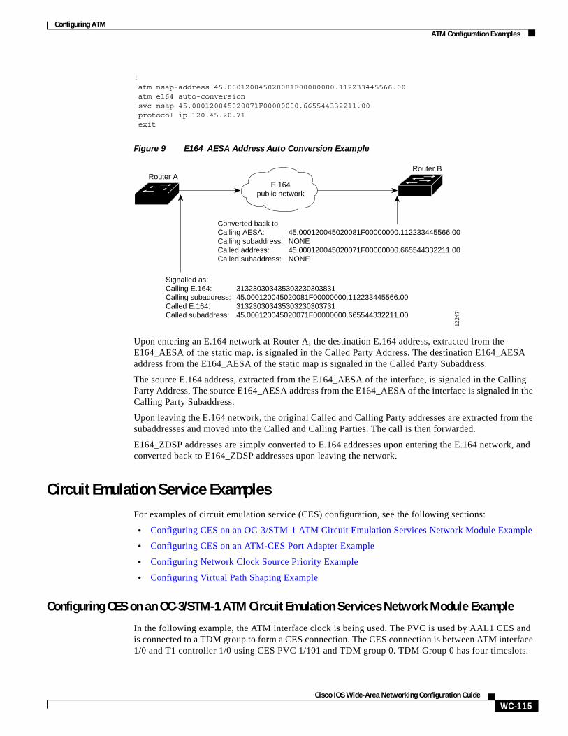
Configuring ATMATM Configuration Examples
WC-115Cisco IOS Wide-Area Networking Configuration Guide
!atm nsap-address 45.000120045020081F00000000.112233445566.00atm e164 auto-conversionsvc nsap 45.000120045020071F00000000.665544332211.00protocol ip 120.45.20.71exit
Figure 9 E164_AESA Address Auto Conversion Example
Upon entering an E.164 network at Router A, the destination E.164 address, extracted from the E164_AESA of the static map, is signaled in the Called Party Address. The destination E164_AESA address from the E164_AESA of the static map is signaled in the Called Party Subaddress.
The source E.164 address, extracted from the E164_AESA of the interface, is signaled in the Calling Party Address. The source E164_AESA address from the E164_AESA of the interface is signaled in the Calling Party Subaddress.
Upon leaving the E.164 network, the original Called and Calling Party addresses are extracted from the subaddresses and moved into the Called and Calling Parties. The call is then forwarded.
E164_ZDSP addresses are simply converted to E.164 addresses upon entering the E.164 network, and converted back to E164_ZDSP addresses upon leaving the network.
Circuit Emulation Service ExamplesFor examples of circuit emulation service (CES) configuration, see the following sections:
• Configuring CES on an OC-3/STM-1 ATM Circuit Emulation Services Network Module Example
• Configuring CES on an ATM-CES Port Adapter Example
• Configuring Network Clock Source Priority Example
• Configuring Virtual Path Shaping Example
Configuring CES on an OC-3/STM-1 ATM Circuit Emulation Services Network Module Example
In the following example, the ATM interface clock is being used. The PVC is used by AAL1 CES and is connected to a TDM group to form a CES connection. The CES connection is between ATM interface 1/0 and T1 controller 1/0 using CES PVC 1/101 and TDM group 0. TDM Group 0 has four timeslots.
E.164public network
1224
7
Router ARouter B
Signalled as:Calling E.164: 313230303435303230303831Calling subaddress: 45.000120045020081F00000000.112233445566.00Called E.164: 313230303435303230303731Called subaddress: 45.000120045020071F00000000.665544332211.00
Converted back to:Calling AESA: 45.000120045020081F00000000.112233445566.00Calling subaddress: NONECalled address: 45.000120045020071F00000000.665544332211.00Called subaddress: NONE
Configuring ATMATM Configuration Examples
WC-116Cisco IOS Wide-Area Networking Configuration Guide
hostname vpd2005!logging buffered 4096 debuggingno logging console!!ces 1/0clock-select 1 em1/0! this is the default
!ip subnet-zeroip host lab 172.18.207.11ip host rtplab 172.18.207.11ip host rtpss20 172.18.207.11ip host dev 172.18.207.10ip host rtpdev 172.18.207.10!isdn voice-call-failure 0cns event-service server!controller T1 1/0 clock source internal tdm-group 0 timeslots 4-8!controller T1 1/1 clock source internal tdm-group 1 timeslots 1!!interface Ethernet0/0 ip address 172.18.193.220 255.255.255.0 no ip directed-broadcast! interface Ethernet0/1 no ip address no ip directed-broadcast!interface Ethernet0/2 no ip address no ip directed-broadcast!interface Ethernet0/3 no ip address no ip directed-broadcast!interface ATM1/0 ip address 7.7.7.7 255.255.255.0 no ip directed-broadcast no atm ilmi-keepalive pvc 1/101 ces pvc 1/200 protocol ip 7.7.7.8 broadcast!ip classlessip route 0.0.0.0 0.0.0.0 Ethernet0/0ip route 0.0.0.0 0.0.0.0 172.18.193.1ip route 12.0.0.0 255.0.0.0 1.1.1.1no ip http server!
connect test ATM1/0 1/101 T1 1/0 0!line con 0
Configuring ATMATM Configuration Examples
WC-117Cisco IOS Wide-Area Networking Configuration Guide
exec-timeout 0 0 transport input noneline aux 0line vty 0 4 password lab login!end
Configuring CES on an ATM-CES Port Adapter Example
The following example shows how to configure the T1 port on the ATM-CES port adapter for unstructured (clear channel) CES services. In this example, the T1 port uses adaptive clocking and the circuit name “CBR-PVC-A.” For further information, refer to the section “Configuring Circuit Emulation Services” earlier in this chapter.
interface cbr 6/0ces aal1 service unstructuredces aal1 clock adaptiveatm clock internalces dsx1 clock network-derivedces circuit 0 circuit-name CBR-PVC-Aces pvc 0 interface atm 6/0 vpi 0 vci 512no shutdownno ces circuit 0 shutdownexit
Configuring Network Clock Source Priority Example
The following example shows how to establish the T1 port on the ATM-CES port adapter as the first clocking priority and the ATM port as the second clocking priority. For further information, refer to the section “Configuring Network Clock Source and Priorities” earlier in this chapter.
network-clock-select 1 cbr 6/0network-clock-select 2 atm 6/0exit
Configuring Virtual Path Shaping Example
The following example shows a typical configuration for the ATM-CES port adapter with VP shaping on a Cisco 7200 series router. In this example, a VP is created with the VPI value of 1 and with a peak rate of 2000 kbps. The subsequent VCs created, one data VC and one CES VC, are multiplexed onto this VP. For further information, refer to the section “Configuring Virtual Path Shaping” earlier in this chapter.
interface atm 6/0ip address 2.2.2.2 255.255.255.0atm pvp 1 2000pvc 1/33no shutdownexit
interface cbr 6/1ces circuit 0ces pvc 0 interface atm6/0 vpi 1 vci 100exit
Configuring ATMATM Configuration Examples
WC-118Cisco IOS Wide-Area Networking Configuration Guide
ATM Access over a Serial Interface ExampleThe following example shows how to configure a serial interface for ATM access.
In the following example, serial interface 0 is configured for ATM-DXI with MUX encapsulation. Because MUX encapsulation is used, only one protocol is carried on the PVC. This protocol is explicitly identified by a dxi map command, which also identifies the protocol address of the remote node. This PVC can carry IP broadcast traffic.
interface serial 0ip address 172.21.178.48encapsulation atm-dxidxi pvc 10 10 muxdxi map ip 172.21.178.4 10 10 broadcast
ATM Port Adapters Connected Back-to-Back ExampleThe following example shows how to connect two ATM port adapters back to back. Two routers, each containing an ATM port adapter, are connected directly with a standard cable, which allows you to verify the operation of the ATM port or to directly link the routers to build a larger node.
By default, the ATM port adapter expects a connected ATM switch to provide transmit clocking. To specify that the ATM port adapter generates the transmit clock internally for SONET PLIM operation, add the atm clock internal command to your configuration.
Router Ainterface atm 3/0ip address 192.168.1.10 255.0.0.0no keepaliveatm clock internalpvc 1/35
!protocol ip 192.168.1.20 broadcast
Router Binterface atm 3/0ip address 192.168.1.20 255.0.0.0no keepaliveatm clock internalpvc 1/35
!protocol ip 192.168.1.10 broadcast


![Cisco Expressway Basic Configuration...Routing configuration: n Task 6: Configuring transforms [p.14] n Task 7: Configuring the traversal zone [p.15] n Task 8: Configuring traversal](https://static.fdocuments.us/doc/165x107/5f0b3e977e708231d42f8ee9/cisco-expressway-basic-configuration-routing-configuration-n-task-6-configuring.jpg)