ATEX Instruction; PAHT G 2-90 in dust applications -...
10
danfoss.high-pressurepumps.com Instruction ATEX instruction for PAHT G 2-90 in dust applications MAKING MODERN LIVING POSSIBLE
Transcript of ATEX Instruction; PAHT G 2-90 in dust applications -...
danfoss.high-pressurepumps.com
Instruction
ATEX instruction forPAHT G 2-90 in dust applications
MAKING MODERN LIVING POSSIBLE
Instruction ATEX instruction for PAHT G 2-90 in dust applications
2 180R9313 / DKCFN.PI.012.B2.02 / 521B1305 / 06.2013
Table of Contents
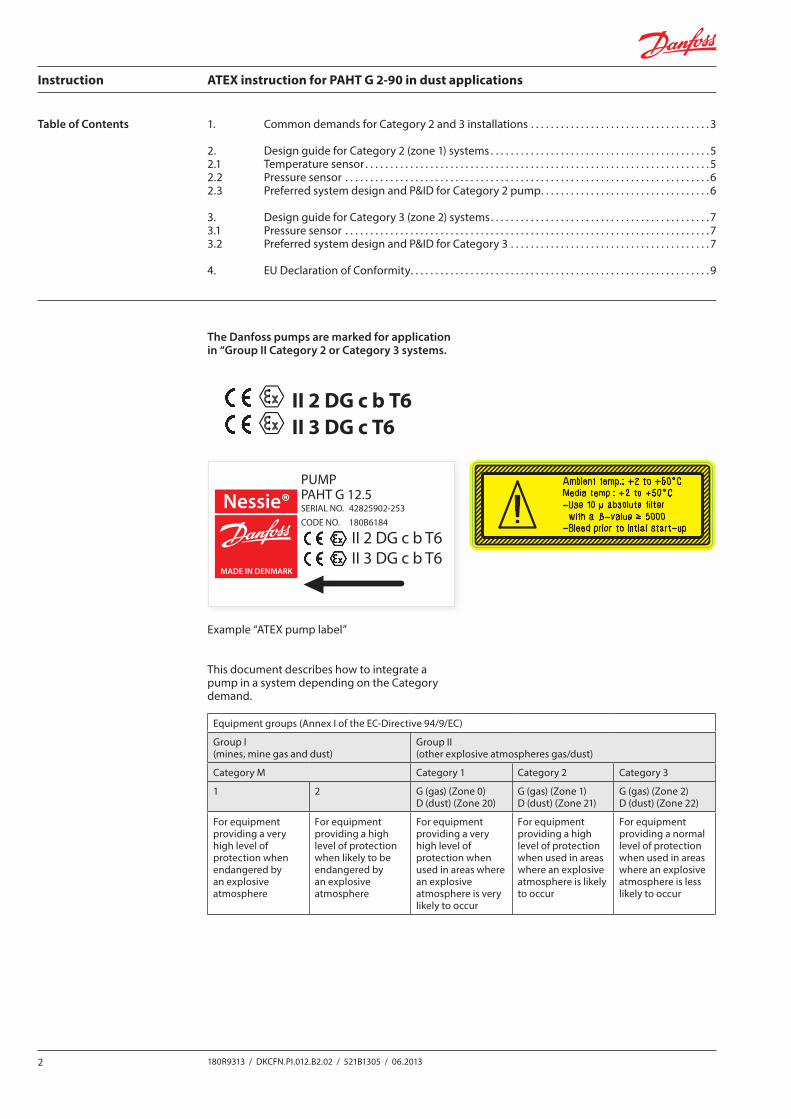
The Danfoss pumps are marked for application in “Group II Category 2 or Category 3 systems.
II 3 DG c T6II 2 DG c b T6
Example “ATEX pump label”
This document describes how to integrate a pump in a system depending on the Category demand.
1. Common demands for Category 2 and 3 installations . . . . . . . . . . . . . . . . . . . . . . . . . . . . . . . . . . . . 3
2. Design guide for Category 2 (zone 1) systems . . . . . . . . . . . . . . . . . . . . . . . . . . . . . . . . . . . . . . . . . . . . 52.1 Temperature sensor . . . . . . . . . . . . . . . . . . . . . . . . . . . . . . . . . . . . . . . . . . . . . . . . . . . . . . . . . . . . . . . . . . . . . 52.2 Pressure sensor . . . . . . . . . . . . . . . . . . . . . . . . . . . . . . . . . . . . . . . . . . . . . . . . . . . . . . . . . . . . . . . . . . . . . . . . . 62.3 Preferred system design and P&ID for Category 2 pump. . . . . . . . . . . . . . . . . . . . . . . . . . . . . . . . . . 6
3. Design guide for Category 3 (zone 2) systems. . . . . . . . . . . . . . . . . . . . . . . . . . . . . . . . . . . . . . . . . . . . 73.1 Pressure sensor . . . . . . . . . . . . . . . . . . . . . . . . . . . . . . . . . . . . . . . . . . . . . . . . . . . . . . . . . . . . . . . . . . . . . . . . . 73.2 Preferred system design and P&ID for Category 3 . . . . . . . . . . . . . . . . . . . . . . . . . . . . . . . . . . . . . . . . 7
4. EU Declaration of Conformity. . . . . . . . . . . . . . . . . . . . . . . . . . . . . . . . . . . . . . . . . . . . . . . . . . . . . . . . . . . . 9
Equipment groups (Annex I of the EC-Directive 94/9/EC)
Group I (mines, mine gas and dust)
Group II (other explosive atmospheres gas/dust)
Category M Category 1 Category 2 Category 3
1 2 G (gas) (Zone 0)D (dust) (Zone 20)
G (gas) (Zone 1)D (dust) (Zone 21)
G (gas) (Zone 2)D (dust) (Zone 22)
For equipment providing a very high level of protection when endangered by an explosive atmosphere
For equipment providing a high level of protection when likely to be endangered by an explosive atmosphere
For equipment providing a very high level of protection when used in areas where an explosive atmosphere is very likely to occur
For equipment providing a high level of protection when used in areas where an explosive atmosphere is likely to occur
For equipment providing a normal level of protection when used in areas where an explosive atmosphere is less likely to occur
Kunde: Danfoss A/SKontaktperson: Carsten Matthiesen
Repro:
Farver og papirkvalitet på dette digitale print kan variere i forhold til det endelige tryk.
Etiketnavn/nr.: Warning 180A0025Format: 30 x 85 mmMateriale: 3M 3692E 90WG Blank GulSkala: 1:1 - (alle mål i mm)
Dato: 31.05.2013 Ordre nr.: 111546Etiket nr.: 180A0025
Korrektur nr.
Fax: 74 53 47 73
1LD
Evt. bemærkning: -
Godkendt med rettelser uden ny fremsendt korr.Godkendt.
Udfyldes af kunde:
Retur med rettelser. Ny korrektur ønskes.Dato/Underskrift.
Returnér venligst tegningen, i underskreven stand inden 3 dage, hvis aftalt leveringstid skal kunne overholdes.
Udvendig nr. 1
Udvendig nr. 2
Udvendig nr. 3
Udvendig nr. 4
Indvendig nr. 1
Indvendig nr. 2
Indvendig nr. 3
Indvendig nr. 4
Kerne- diameter
25-40-45-76
Udvendig diameter max.
mm
mm
Antaletiketterpr. rulle
stk.
SPOLERETNING
Antalmeterpr. rulle
m
tommercm
Afstandpr. slag
Z-falset
Sort
Gul
-
-
-
-
-
-
FARVER:
40
1000
grafiketIndikerer Etiketstansen
Nessie®
MADE IN DENMARK
PUMPPAHT G 12.5SERIAL NO. 42825902-253CODE NO. 180B6184
II 2 DG c b T6 II 3 DG c b T6
Instruction ATEX instruction for PAHT G 2-90 in dust applications
3180R9313 / DKCFN.PI.012.B2.02 / 521B1305 / 06.2013
1. Common demands for Category 2 and 3 installations
This instruction is a supplement to existing product instruction as ATEX components are subject to some limitations compared to standard components. The limitations are described in this ATEX instruction.
Validity: Approvals are only related to water as fluid. If other fluids are used these must be non-flamma-ble fluids.
The pumps are designed to pump liquids and not gasses! It is the user’s responsibility to ensure that the pump is fluid filled during start-up and operation.
Fluids:If the pump is to operate on other fluids than water, please contact Danfoss. Other operation and maintenance conditions might apply.
Minimum suction pressure:The user must always ensure that the pump is bleeded. The pumps must always be operated with a “positive head” on suction port. The allowable minimum and maximum inlet pressure for the suction port can be found in the pump data sheet.
Maximum discharge pressure:It is the user’s responsibility that the pump discharge pressure does not exceed the max continuous discharge pressure stated in the pump data sheet.
Temperature: The pump is not to be operated in systems where the fluid temperature exceeds 50 °C/122 °F.
Filtration:The fluids entering the pump must as a minimum always be filtered according to the specification found in the pump data sheet.
External impacts due to:Gases: The pumps are made in materials resistant to most common gases. The user of the pump must ensure that materials used are resistant to the gases applied.
In ATEX dust applications, the layer of dust may never exceed 5 mm [0.002 inch], we recommend to paint the components in contrasting colors, to make deposits more visible.
Assembly of pump drive unit:Motor - Pump assembly and system integration:When assembling the pump with the bell housing, flexible couplings and motor, it is the builder’s responsibility that the parts used conform to the ATEX directive and that the components are assembled and running according to the operational data/design found in product data sheets and instructions.
In order to avoid dust accumulations, the system design must be with smooth surfaces and with as few dead spaces as possible.
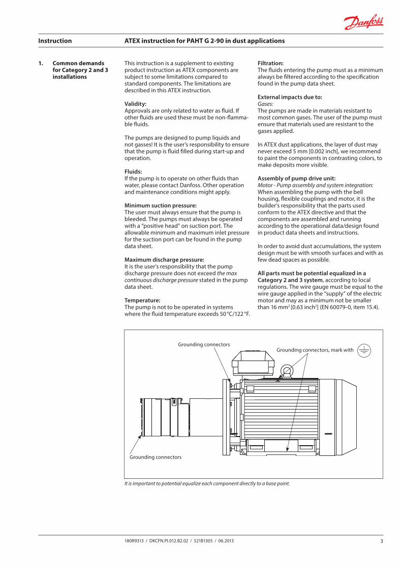
All parts must be potential equalized in a Category 2 and 3 system, according to local regulations. The wire gauge must be equal to the wire gauge applied in the “supply” of the electric motor and may as a minimum not be smaller than 16 mm2 [0.63 inch2] (EN 60079-0, item 15.4).
It is important to potential equalize each component directly to a base point.
Grounding connectors
Grounding connectorsGrounding connectors, mark with
Instruction ATEX instruction for PAHT G 2-90 in dust applications
4 180R9313 / DKCFN.PI.012.B2.02 / 521B1305 / 06.2013
Choice of bell housing and couplingThe material for the bell housing can be steel, stainless steel or aluminium with a magnesium content below 7,5%.
The bell housing must have an inspection and a drain hole. The drain hole must be placed at the lowest point to ensure the fluid can get out if there is a small leak from the pump shaft seal.
In dust applications, the bell housing, which covers the rotating parts, must minimum be an IP5x, dust proof.
Make sure that inspection and drain holes are dust proof and we recommend often inspecting for dust or fluid accumulations.
The dust may not come in contact with rotating parts, as this can cause an increased tempera-ture.
The distance between bell housing and the rotating parts must be at least 5 mm [0.2 inch].Coupling for use in hazardous areas are marked with regard to the respective permissible conditions of use.
Aluminium as coupling material is generally excluded for explosive areas.
See special conditions for safe use in coupling operation- and ATEX instruction from coupling supplier.
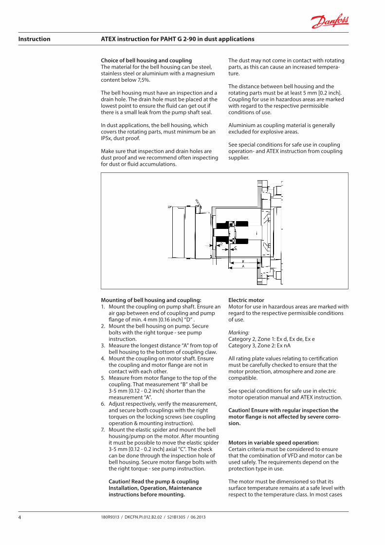
Mounting of bell housing and coupling: 1. Mount the coupling on pump shaft. Ensure an
air gap between end of coupling and pump flange of min. 4 mm [0.16 inch] “D” .
2. Mount the bell housing on pump. Secure bolts with the right torque - see pump instruction.
3. Measure the longest distance “A” from top of bell housing to the bottom of coupling claw.
4. Mount the coupling on motor shaft. Ensure the coupling and motor flange are not in contact with each other.
5. Measure from motor flange to the top of the coupling. That measurement “B” shall be 3-5 mm [0.12 - 0.2 inch] shorter than the measurement “A”.
6. Adjust respectively, verify the measurement, and secure both couplings with the right torques on the locking screws (see coupling operation & mounting instruction).
7. Mount the elastic spider and mount the bell housing/pump on the motor. After mounting it must be possible to move the elastic spider 3-5 mm [0.12 - 0.2 inch] axial “C”. The check can be done through the inspection hole of bell housing. Secure motor flange bolts with the right torque - see pump instruction.
Caution! Read the pump & coupling Installation, Operation, Maintenance instructions before mounting.
Electric motorMotor for use in hazardous areas are marked with regard to the respective permissible conditions of use.
Marking: Category 2, Zone 1: Ex d, Ex de, Ex eCategory 3, Zone 2: Ex nA
All rating plate values relating to certification must be carefully checked to ensure that the motor protection, atmosphere and zone are compatible.
See special conditions for safe use in electric motor operation manual and ATEX instruction.
Caution! Ensure with regular inspection the motor flange is not affected by severe corro-sion.
Motors in variable speed operation:Certain criteria must be considered to ensure that the combination of VFD and motor can be used safely. The requirements depend on the protection type in use.
The motor must be dimensioned so that its surface temperature remains at a safe level with respect to the temperature class. In most cases
Instruction ATEX instruction for PAHT G 2-90 in dust applications
5180R9313 / DKCFN.PI.012.B2.02 / 521B1305 / 06.2013
2. Design guide for Category 2 (zone 1) systems
this requires either combined type tests or the use of direct temperature control.
Caution! Consult motor manufacturers for right dimensioning.
Cabling and electrical connectionsSuitable cable lugs must be used for the connection of all main cables.
The cable connection must fulfil the requirement stated in the national standards for installation or in the standard EN 60204-1 and EN 60079-14.
In addition, earthing or bonding connection facilities on the outside of electrical apparatus must provide effective connection of a conduc-tor.
Caution! Read the Installation, Operation, Maintenance manual of the chosen motor to ensure all applicable warranties.
Failure modes due to operational conditionsFollowing operational conditions can cause a pump failure:• Pump running dry• Too high inlet pressure• Too low inlet pressure• Too high temperature of the fluid being
pumped• Too high ambient temperature• Pump is pumping against blocked port• Pump operate with a non-specified/
approved fluid• Pump running the wrong direction• Non-return valve in front of the pump inlet• Insufficient filtration• Pump is not being serviced accordance to
Danfoss specifications.
Danfoss recommends building systems with a high inherent safety degree. The PI&D on the next pages shows how a high degree of safety can be reached when using a Danfoss pump.
2.1 Temperature sensorPump housing temperature increase causing problems due to pump breakdown/failure in a Category 2 rated system.
In a Category 2 system, the pump housing temperature must be monitored. Pump housing temperature must always be lower than 85 °C / 185 °F.
Surface temperature must never exceed 2/3 of minimum ignition temperature of the dust cloud, not even in the case of malfunctions.
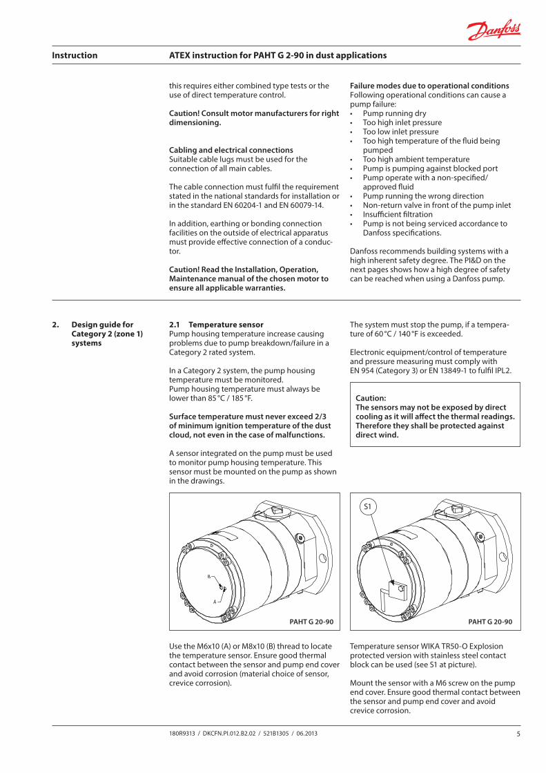
A sensor integrated on the pump must be used to monitor pump housing temperature. This sensor must be mounted on the pump as shown in the drawings.
The system must stop the pump, if a tempera-ture of 60 °C / 140 °F is exceeded.
Electronic equipment/control of temperature and pressure measuring must comply with EN 954 (Category 3) or EN 13849-1 to fulfil IPL2.
Temperature sensor WIKA TR50-O Explosion protected version with stainless steel contact block can be used (see S1 at picture).
Mount the sensor with a M6 screw on the pump end cover. Ensure good thermal contact between the sensor and pump end cover and avoid crevice corrosion.
PAHT G 20-90 PAHT G 20-90
S1
Caution:The sensors may not be exposed by direct cooling as it will affect the thermal readings. Therefore they shall be protected against direct wind.
Use the M6x10 (A) or M8x10 (B) thread to locate the temperature sensor. Ensure good thermal contact between the sensor and pump end cover and avoid corrosion (material choice of sensor, crevice corrosion).
Instruction ATEX instruction for PAHT G 2-90 in dust applications
6 180R9313 / DKCFN.PI.012.B2.02 / 521B1305 / 06.2013
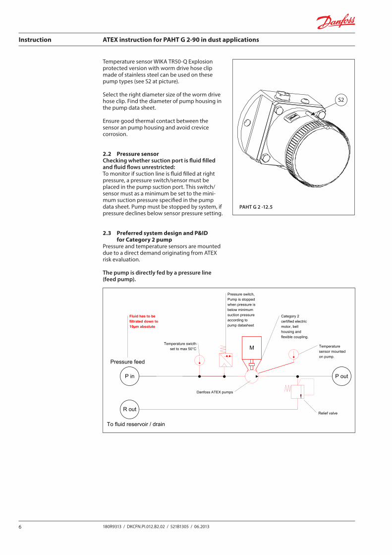
Temperature sensor WIKA TR50-Q Explosion protected version with worm drive hose clip made of stainless steel can be used on these pump types (see S2 at picture).
Select the right diameter size of the worm drive hose clip. Find the diameter of pump housing in the pump data sheet.
Ensure good thermal contact between the sensor an pump housing and avoid crevice corrosion.
2.2 Pressure sensorChecking whether suction port is fluid filled and fluid flows unrestricted:To monitor if suction line is fluid filled at right pressure, a pressure switch/sensor must be placed in the pump suction port. This switch/sensor must as a minimum be set to the mini-mum suction pressure specified in the pump data sheet. Pump must be stopped by system, if pressure declines below sensor pressure setting.
2.3 Preferred system design and P&ID for Category 2 pump
Pressure and temperature sensors are mounted due to a direct demand originating from ATEX risk evaluation.
The pump is directly fed by a pressure line (feed pump).
PAHT G 2 -12.5
S2
M
Typical Category 2 systems
Category 2 certified electric motor, bell housing and flexible coupling.
Pressure switch, Pump is stopped when pressure is below minimum suction pressure according to pump datasheet
P in P out
Danfoss ATEX pumps
Relief valveR out
Pressure feed
To fluid reservoir / drain
Temperature swicth set to max 50°C
M
R
PMinimum Water Level Switch
Maximum Water Temperature Switch set to
50°C
10µm filter
Category 2 certified electric motor, bell housing and flexible coupling.
Danfoss ATEX pumpsTank
Filter Pressure Switch
Temperature sensor mounted on pump.
Fluid has to be filtrated down to 10µm absolute
Instruction ATEX instruction for PAHT G 2-90 in dust applications
7180R9313 / DKCFN.PI.012.B2.02 / 521B1305 / 06.2013
Temperature sensor mounted on pump.
M
Category 2 certified electric motor, bell housing and flexible coupling.
Pressure switch, Pump is stopped when pressure is below minimum suction pressure according to pump datasheet
P in
P out
Danfoss ATEX pumps
Relief valve
Fluid has to be filtrated down to 10µm absolute
Tank
Minimum WaterLevel Switch
Maximum Water Temperature Switchset to 50°C
Typical Category 2 systems
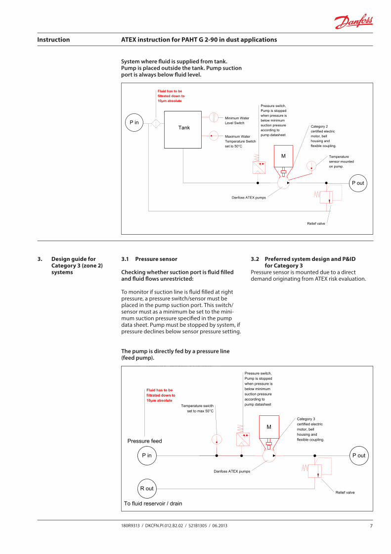
System where fluid is supplied from tank. Pump is placed outside the tank. Pump suction port is always below fluid level.
3. Design guide for Category 3 (zone 2) systems
3.1 Pressure sensor
Checking whether suction port is fluid filled and fluid flows unrestricted:
To monitor if suction line is fluid filled at right pressure, a pressure switch/sensor must be placed in the pump suction port. This switch/sensor must as a minimum be set to the mini-mum suction pressure specified in the pump data sheet. Pump must be stopped by system, if pressure declines below sensor pressure setting.
3.2 Preferred system design and P&ID for Category 3
Pressure sensor is mounted due to a direct demand originating from ATEX risk evaluation.
The pump is directly fed by a pressure line (feed pump).
M
Typical Category 3 systems
Category 3 certified electric motor, bell housing and flexible coupling.
Pressure switch, Pump is stopped when pressure is below minimum suction pressure according to pump datasheet
Fluid has to be filtrated down to 10µm absolute
P in P out
Danfoss ATEX pumps
Relief valveR out
Pressure feed
To fluid reservoir / drain
Temperature swicth set to max 50°C
M
R
PMinimum Water Level Switch
Maximum Water Temperature Switch set to
50°C
10µm filterRelief valve
Category 3 certified electric motor, bell housing and flexible coupling.
Danfoss ATEX pumpsTank
Filter Pressure Switch
Instruction ATEX instruction for PAHT G 2-90 in dust applications
8 180R9313 / DKCFN.PI.012.B2.02 / 521B1305 / 06.2013
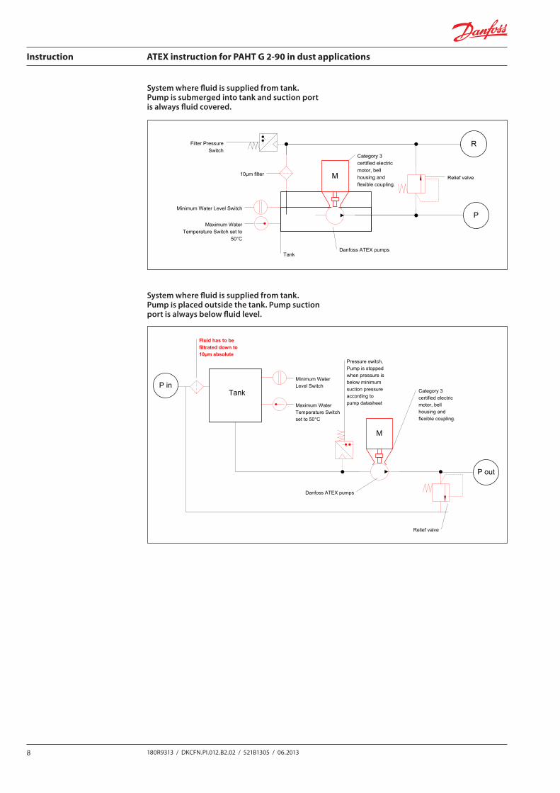
M
Typical Category 3 systems
Category 3 certified electric motor, bell housing and flexible coupling.
Pressure switch, Pump is stopped when pressure is below minimum suction pressure according to pump datasheet
Fluid has to be filtrated down to 10µm absolute
P in P out
Danfoss ATEX pumps
Relief valveR out
Pressure feed
To fluid reservoir / drain
Temperature swicth set to max 50°C
M
R
PMinimum Water Level Switch
Maximum Water Temperature Switch set to
50°C
10µm filterRelief valve
Category 3 certified electric motor, bell housing and flexible coupling.
Danfoss ATEX pumpsTank
Filter Pressure Switch
M
Category 3 certified electric motor, bell housing and flexible coupling.
Pressure switch, Pump is stopped when pressure is below minimum suction pressure according to pump datasheet
P in
P out
Danfoss ATEX pumps
Relief valve
Fluid has to be filtrated down to 10µm absolute
Tank
Minimum WaterLevel Switch
Maximum Water Temperature Switchset to 50°C
Typical Category 3 systems
System where fluid is supplied from tank. Pump is placed outside the tank. Pump suction port is always below fluid level.
System where fluid is supplied from tank. Pump is submerged into tank and suction port is always fluid covered.
9180R9313 / DKCFN.PI.012.B2.02 / 521B1305 / 06.2013
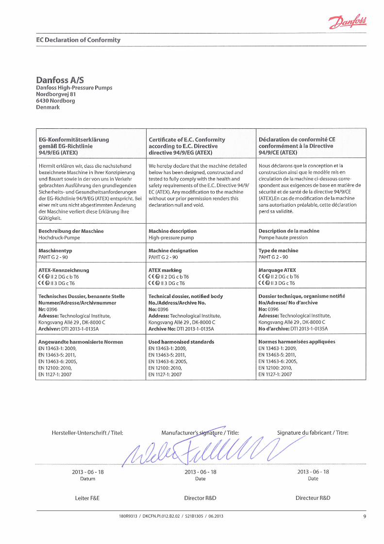
4. EU Declaration of Conformity
Instruction ATEX instruction for PAHT G 2-90 in dust applications
10 180R9313 / DKCFN.PI.012.B2.02 / 521B1305 / 06.2013
Danfoss can accept no responsibility for possible errors in catalogues, brochures and other printed material. Danfoss reserves the right to alter its products without notice. This also applies to products already on order provided that such alterations can be made without subsequential changes being necessary in specifications already agreed.All trademarks in this material are property of the respective companies. Danfoss and the Danfoss logotype are trademarks of Danfoss A/S. All rights reserved.
Danfoss A/SHigh Pressure PumpsDK-6430 NordborgDenmark