Data sheet PAHT 2-308 pumps / PAHT G 2-308 pumps … · gpm 0.6 1.2 1.6 2.7 4.0 5.3 ... Data sheet...
24
danfoss.high-pressurepumps.com Data sheet PAHT 2-308 pumps / PAHT G 2-308 pumps / ATEX PAHT G pump Lenntech [email protected] Tel. +31-152-610-900 www.lenntech.com Fax. +31-152-616-289
Transcript of Data sheet PAHT 2-308 pumps / PAHT G 2-308 pumps … · gpm 0.6 1.2 1.6 2.7 4.0 5.3 ... Data sheet...

danfoss.high-pressurepumps.com
Data sheet
PAHT 2-308 pumps /PAHT G 2-308 pumps /ATEX PAHT G pump
[email protected] Tel. +31-152-610-900www.lenntech.com Fax. +31-152-616-289
Data sheet PAHT 2-308, PAHT G 2-308 and ATEX PAHT G pumps
2 521B1247 / DKCFN.PD.012.M3.02 / 06.2014
1. Introduction . . . . . . . . . . . . . . . . . . . . . . . . . . . . . . . . . . . . . . . . . . . . . . . . . . . . . . . . . . . . . . . . . . . . . . . . . . . . 2
2. Benefits. . . . . . . . . . . . . . . . . . . . . . . . . . . . . . . . . . . . . . . . . . . . . . . . . . . . . . . . . . . . . . . . . . . . . . . . . . . . . . . . . 3
3. Application examples . . . . . . . . . . . . . . . . . . . . . . . . . . . . . . . . . . . . . . . . . . . . . . . . . . . . . . . . . . . . . . . . . . . 3
4. Technical data . . . . . . . . . . . . . . . . . . . . . . . . . . . . . . . . . . . . . . . . . . . . . . . . . . . . . . . . . . . . . . . . . . . . . . . . . . 44.1 PAHT 2-12.5 . . . . . . . . . . . . . . . . . . . . . . . . . . . . . . . . . . . . . . . . . . . . . . . . . . . . . . . . . . . . . . . . . . . . . . . . . . . . . 44.2 PAHT 20-32 . . . . . . . . . . . . . . . . . . . . . . . . . . . . . . . . . . . . . . . . . . . . . . . . . . . . . . . . . . . . . . . . . . . . . . . . . . . . . 54.3 PAHT 50-90 . . . . . . . . . . . . . . . . . . . . . . . . . . . . . . . . . . . . . . . . . . . . . . . . . . . . . . . . . . . . . . . . . . . . . . . . . . . . . 64.4 PAHT 256-308. . . . . . . . . . . . . . . . . . . . . . . . . . . . . . . . . . . . . . . . . . . . . . . . . . . . . . . . . . . . . . . . . . . . . . . . . . . 7
5. Flow . . . . . . . . . . . . . . . . . . . . . . . . . . . . . . . . . . . . . . . . . . . . . . . . . . . . . . . . . . . . . . . . . . . . . . . . . . . . . . . . . . . . 85.1 PAHT 2-6.3 typical flow curves at max pressure . . . . . . . . . . . . . . . . . . . . . . . . . . . . . . . . . . . . . . . . . . 85.2 PAHT 10-12.5 typical flow curves at max pressure . . . . . . . . . . . . . . . . . . . . . . . . . . . . . . . . . . . . . . . . 95.3 PAHT 20-32 typical flow curves at max pressure . . . . . . . . . . . . . . . . . . . . . . . . . . . . . . . . . . . . . . . . .105.4 PAHT 50-90 typical flow curves at max pressure. . . . . . . . . . . . . . . . . . . . . . . . . . . . . . . . . . . . . . . . . 115.5 PAHT 256-308 typical flow curves at max pressure . . . . . . . . . . . . . . . . . . . . . . . . . . . . . . . . . . . . . .12
6. Motor requirements. . . . . . . . . . . . . . . . . . . . . . . . . . . . . . . . . . . . . . . . . . . . . . . . . . . . . . . . . . . . . . . . . . . .13
7. Installation. . . . . . . . . . . . . . . . . . . . . . . . . . . . . . . . . . . . . . . . . . . . . . . . . . . . . . . . . . . . . . . . . . . . . . . . . . . . .147.1 Filtration . . . . . . . . . . . . . . . . . . . . . . . . . . . . . . . . . . . . . . . . . . . . . . . . . . . . . . . . . . . . . . . . . . . . . . . . . . . . . .147.2 Noise . . . . . . . . . . . . . . . . . . . . . . . . . . . . . . . . . . . . . . . . . . . . . . . . . . . . . . . . . . . . . . . . . . . . . . . . . . . . . . . . . .147.3 Open-system design . . . . . . . . . . . . . . . . . . . . . . . . . . . . . . . . . . . . . . . . . . . . . . . . . . . . . . . . . . . . . . . . . . .157.4 Closed-system design . . . . . . . . . . . . . . . . . . . . . . . . . . . . . . . . . . . . . . . . . . . . . . . . . . . . . . . . . . . . . . . . .16
8. Dimensions and connections. . . . . . . . . . . . . . . . . . . . . . . . . . . . . . . . . . . . . . . . . . . . . . . . . . . . . . . . . . .178.1 PAHT 2-6.3 . . . . . . . . . . . . . . . . . . . . . . . . . . . . . . . . . . . . . . . . . . . . . . . . . . . . . . . . . . . . . . . . . . . . . . . . . . . . .178.2 PAHT 10-12.5. . . . . . . . . . . . . . . . . . . . . . . . . . . . . . . . . . . . . . . . . . . . . . . . . . . . . . . . . . . . . . . . . . . . . . . . . . .188.3 PAHT 20 . . . . . . . . . . . . . . . . . . . . . . . . . . . . . . . . . . . . . . . . . . . . . . . . . . . . . . . . . . . . . . . . . . . . . . . . . . . . . . .198.4 PAHT 25-32 . . . . . . . . . . . . . . . . . . . . . . . . . . . . . . . . . . . . . . . . . . . . . . . . . . . . . . . . . . . . . . . . . . . . . . . . . . . .208.5 PAHT 50-90 . . . . . . . . . . . . . . . . . . . . . . . . . . . . . . . . . . . . . . . . . . . . . . . . . . . . . . . . . . . . . . . . . . . . . . . . . . . .218.6 PAHT 256-308. . . . . . . . . . . . . . . . . . . . . . . . . . . . . . . . . . . . . . . . . . . . . . . . . . . . . . . . . . . . . . . . . . . . . . . . . .22
9. Service. . . . . . . . . . . . . . . . . . . . . . . . . . . . . . . . . . . . . . . . . . . . . . . . . . . . . . . . . . . . . . . . . . . . . . . . . . . . . . . . .23
The Danfoss range of PAHT and PAHT G high-pressure pumps is specifically designed for use with technical water such as:
• Ultra-pure water that has undergone multiple reverse osmosis processes
• De-ionized water• Demineralized water
Danfoss PAHT pumps are positive displacement pumps, with axial pistons that move a fixed amount of water in each cycle. Flow is propor-tional to the number of input shaft revolutions (rpm). Unlike centrifugal pumps, they produce the same flow at a given speed independently of no matter what the discharge pressure.
The range of PAHT G pumps is based on the standard PAHT pump series. The PAHT G pumps are made with extra coatings that reduce the wear of the pump. This coating is particularly important for pumps used in gas turbine applications or other similar applications where the wear of the pumps is higher due to the ultra pure water quality.
The next pages will cover both PAHT, PAHT G and PAHT G ATEX pumps with the name PAHT pumps.
1. Introduction
Table of Contents
Data sheet PAHT 2-308, PAHT G 2-308 and ATEX PAHT G pumps
3521B1247 / DKCFN.PD.012.M3.02 / 06.2014
2. Benefits • Zero risk of lubricant contamination: - Oil lubricants are replaced with the
pumped medium, water, so there is no contamination risk from the pump.
• Low maintenance costs: - Efficient design and all-stainless steel
construction ensure exceptionally long lifetime. When Danfoss specifications are met, service intervals of up to 8,000 hours can be expected. Service is easy, and can be carried out on site due to the simple design and few parts.
• Low energy costs: - The highly efficient axial piston design
provides the lowest energy consump-tion of any comparable pump on the market.
• Easy installation: - The lightest and most compact design
available.
- Pump can be installed horizontally or vertically.
- No pulsation dampeners necessary due to extremely low-pressure pulsation.
- Powered by electric motors or combus-tion engines.
- Suitable for both boosted inlet pressure and water supply from a tank.
- No need for cooling circuits due to very high mechanical efficiency.
• Certified quality: - Fulfills the stringent hygiene require-
ments, VDI 6022, HACCP. - Certificates:
ISO 9001, ISO 14001 ATEX available on PAHT G,
API available on request
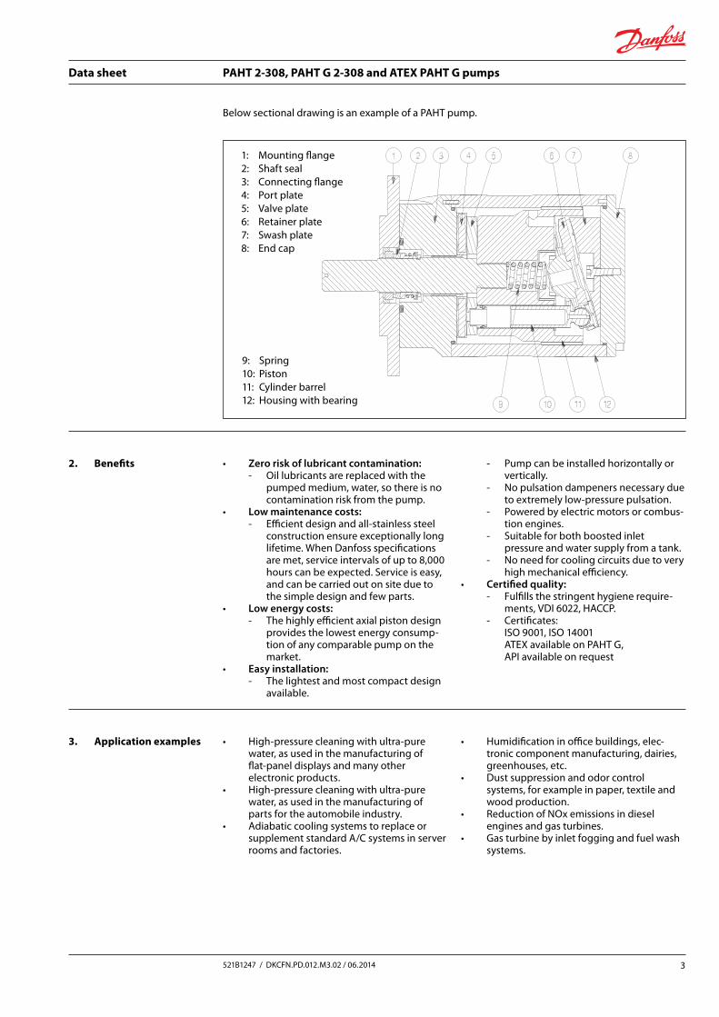
Below sectional drawing is an example of a PAHT pump.
3. Application examples • High-pressure cleaning with ultra-pure water, as used in the manufacturing of flat-panel displays and many other electronic products.
• High-pressure cleaning with ultra-pure water, as used in the manufacturing of parts for the automobile industry.
• Adiabatic cooling systems to replace or supplement standard A/C systems in server rooms and factories.
• Humidification in office buildings, elec-tronic component manufacturing, dairies, greenhouses, etc.
• Dust suppression and odor control systems, for example in paper, textile and wood production.
• Reduction of NOx emissions in diesel engines and gas turbines.
• Gas turbine by inlet fogging and fuel wash systems.
1: Mounting flange2: Shaft seal3: Connecting flange4: Port plate5: Valve plate6: Retainer plate7: Swash plate8: End cap
9: Spring10: Piston11: Cylinder barrel12: Housing with bearing
Data sheet PAHT 2-308, PAHT G 2-308 and ATEX PAHT G pumps
4 521B1247 / DKCFN.PD.012.M3.02 / 06.2014
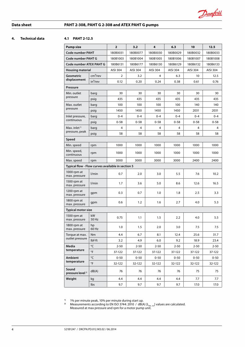
4. Technical data 4.1 PAHT 2-12.5
Pump size 2 3.2 4 6.3 10 12.5
Code number PAHT 180B0031 180B0077 180B0030 180B0029 180B0032 180B0033
Code number PAHT G 180B1003 180B1004 180B1005 180B1006 180B1007 180B1008
Code number ATEX PAHT G 180B6131 180B6177 180B6130 180B6129 180B6132 180B6133
Housing material AISI 304 AISI 304 AISI 304 AISI 304 AISI 304 AISI 304
Geometric displacement
cm³/rev 2 3.2 4 6.3 10 12.5
in³/rev 0.12 0.20 0.24 0.38 0.61 0.76
Pressure
Min. outlet pressure
barg 30 30 30 30 30 30
psig 435 435 435 435 435 435
Max. outlet pressure
barg 100 100 100 100 140 140
psig 1450 1450 1450 1450 2031 2031
Inlet pressure, continuous
barg 0-4 0-4 0-4 0-4 0-4 0-4
psig 0-58 0-58 0-58 0-58 0-58 0-58
Max. inlet 1)
pressure, peakbarg 4 4 4 4 4 4
psig 58 58 58 58 58 58
Speed
Min. speed rpm 1000 1000 1000 1000 1000 1000
Min. speed, continuous rpm 1000 1000 1000 1000 1000 1000
Max. speed rpm 3000 3000 3000 3000 2400 2400
Typical flow - Flow curves available in section 5
1000 rpm at max. pressure l/min 0.7 2.0 3.0 5.5 7.6 10.2
1500 rpm at max. pressure l/min 1.7 3.6 5.0 8.6 12.6 16.5
1200 rpm at max. pressure gpm 0.3 0.7 1.0 1.8 2.5 3.3
1800 rpm at max. pressure gpm 0.6 1.2 1.6 2.7 4.0 5.3
Typical motor size
1500 rpm at max. pressure
kW50 Hz 0.75 1.1 1.5 2.2 4.0 5.5
1800 rpm at max. pressure
hp60 Hz 1.0 1.5 2.0 3.0 7.5 7.5
Torque at max. outlet pressure
Nm 4.4 6.7 8.1 12.4 25.6 31.7
lbf-ft 3.2 4.9 6.0 9.2 18.9 23.4
Media temperature
°C 2-50 2-50 2-50 2-50 2-50 2-50
°F 37-122 37-122 37-122 37-122 37-122 37-122
Ambient temperature
°C 0-50 0-50 0-50 0-50 0-50 0-50
°F 32-122 32-122 32-122 32-122 32-122 32-122
Sound pressure level 2) dB(A) 76 76 76 76 75 75
Weight kg 4.4 4.4 4.4 4.4 7.7 7.7
lbs 9.7 9.7 9.7 9.7 17.0 17.0
1) 1% per minute peak, 10% per minute during start up.2) Measurements according to EN ISO 3744: 2010 / dB(A) [LPA, 1m] values are calculated. Measured at max pressure and rpm for a motor pump unit.
Data sheet PAHT 2-308, PAHT G 2-308 and ATEX PAHT G pumps
5521B1247 / DKCFN.PD.012.M3.02 / 06.2014
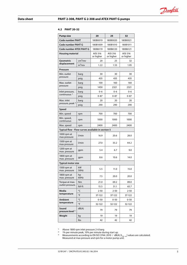
Pump size 20 25 32
Code number PAHT 180B0019 180B0020 180B0021
Code number PAHT G 180B1009 180B1010 180B1011
Code number ATEX PAHT G 180B6119 180B6120 180B6121
Housing material AISI 316 or higher
AISI 316 or higher
AISI 316 or higher
Geometric displacement
cm³/rev 20 25 32
in³/rev 1.22 1.53 1.95
Pressure
Min. outlet pressure
barg 30 30 30
psig 435 435 435
Max. outlet pressure
barg 100 160 160
psig 1450 2321 2321
Inlet pressure, continuous 1)
barg 0-6 0-6 0-6
psig 0-87 0-87 0-87
Max. inlet pressure, peak 2)
barg 20 20 20
psig 290 290 290
Speed
Min. speed rpm 700 700 700
Min. speed, continuous rpm 1000 1000 1000
Max. speed rpm 2400 2400 2400
Typical flow - Flow curves available in section 5
1000 rpm at max pressure l/min 16.9 20.6 28.0
1500 rpm at max pressure l/min 27.0 33.2 44.2
1200 rpm at max. pressure gpm 5.4 6.7 9.0
1800 rpm at max. pressure gpm 8.6 10.6 14.0
Typical motor size
1500 rpm at max. pressure
kW50Hz 5.5 11.0 15.0
1800 rpm at max. pressure
hp60Hz 7.5 20.0 20.0
Torque at max. outlet pressure
Nm 21.0 69.2 89.0
lbf-ft 15.5 51.1 65.7
Media temperature
°C 2-50 2-50 2-50
°F 37-122 37-122 37-122
Ambient temperature
°C 0-50 0-50 0-50
°F 32-122 32-122 32-122
Sound pressure level 3)
dB(A) 79 79 79
Weight kg 19 19 19
lbs 42 42 42
4.2 PAHT 20-32
1) Above 1800 rpm inlet pressure 2-6 barg2) 1% per minute peak, 10% per minute during start up.3) Measurements according to EN ISO 3744: 2010 / dB(A) [LPA, 1m] values are calculated.
Measured at max pressure and rpm for a motor pump unit.
Data sheet PAHT 2-308, PAHT G 2-308 and ATEX PAHT G pumps
6 521B1247 / DKCFN.PD.012.M3.02 / 06.2014
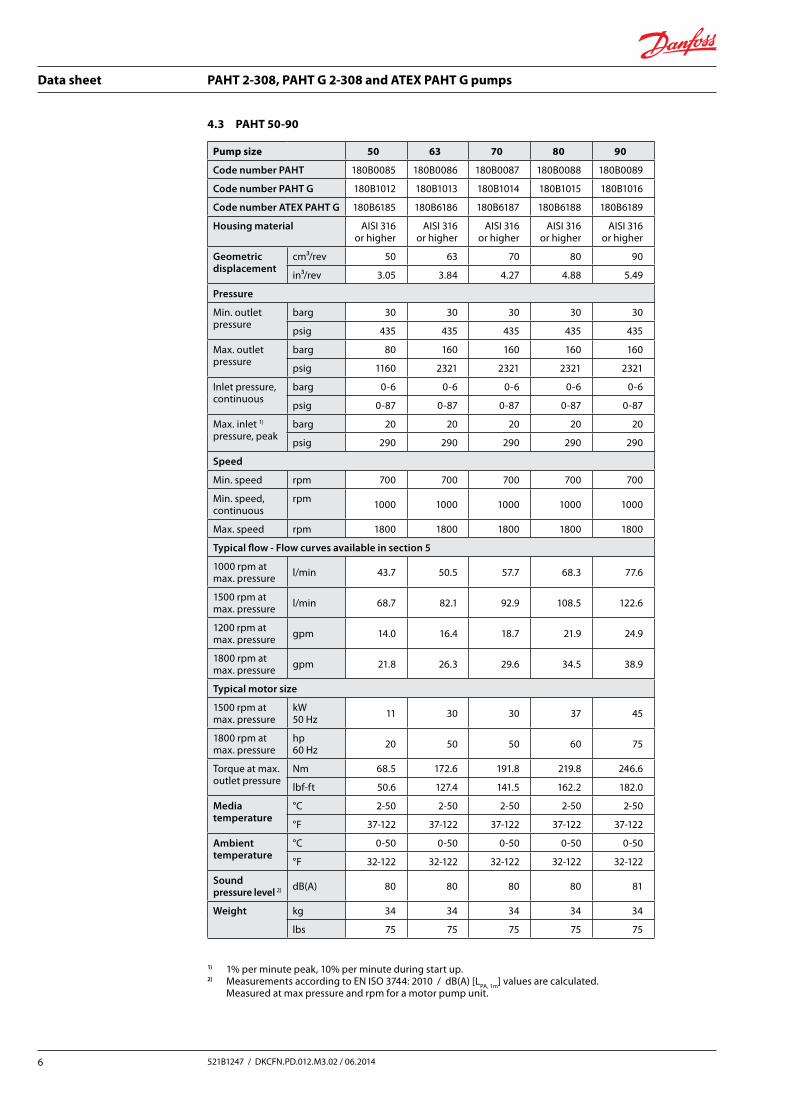
Pump size 50 63 70 80 90
Code number PAHT 180B0085 180B0086 180B0087 180B0088 180B0089
Code number PAHT G 180B1012 180B1013 180B1014 180B1015 180B1016
Code number ATEX PAHT G 180B6185 180B6186 180B6187 180B6188 180B6189
Housing material AISI 316 or higher
AISI 316 or higher
AISI 316 or higher
AISI 316 or higher
AISI 316 or higher
Geometric displacement
cm³/rev 50 63 70 80 90
in³/rev 3.05 3.84 4.27 4.88 5.49
Pressure
Min. outlet pressure
barg 30 30 30 30 30
psig 435 435 435 435 435
Max. outlet pressure
barg 80 160 160 160 160
psig 1160 2321 2321 2321 2321
Inlet pressure, continuous
barg 0-6 0-6 0-6 0-6 0-6
psig 0-87 0-87 0-87 0-87 0-87
Max. inlet 1)
pressure, peakbarg 20 20 20 20 20
psig 290 290 290 290 290
Speed
Min. speed rpm 700 700 700 700 700
Min. speed,continuous
rpm 1000 1000 1000 1000 1000
Max. speed rpm 1800 1800 1800 1800 1800
Typical flow - Flow curves available in section 5
1000 rpm at max. pressure l/min 43.7 50.5 57.7 68.3 77.6
1500 rpm at max. pressure l/min 68.7 82.1 92.9 108.5 122.6
1200 rpm at max. pressure gpm 14.0 16.4 18.7 21.9 24.9
1800 rpm at max. pressure gpm 21.8 26.3 29.6 34.5 38.9
Typical motor size
1500 rpm at max. pressure
kW50 Hz 11 30 30 37 45
1800 rpm at max. pressure
hp60 Hz 20 50 50 60 75
Torque at max. outlet pressure
Nm 68.5 172.6 191.8 219.8 246.6
lbf-ft 50.6 127.4 141.5 162.2 182.0
Media temperature
°C 2-50 2-50 2-50 2-50 2-50
°F 37-122 37-122 37-122 37-122 37-122
Ambient temperature
°C 0-50 0-50 0-50 0-50 0-50
°F 32-122 32-122 32-122 32-122 32-122
Sound pressure level 2) dB(A) 80 80 80 80 81
Weight kg 34 34 34 34 34
lbs 75 75 75 75 75
4.3 PAHT 50-90
1) 1% per minute peak, 10% per minute during start up.2) Measurements according to EN ISO 3744: 2010 / dB(A) [LPA, 1m] values are calculated.
Measured at max pressure and rpm for a motor pump unit.
Data sheet PAHT 2-308, PAHT G 2-308 and ATEX PAHT G pumps
7521B1247 / DKCFN.PD.012.M3.02 / 06.2014
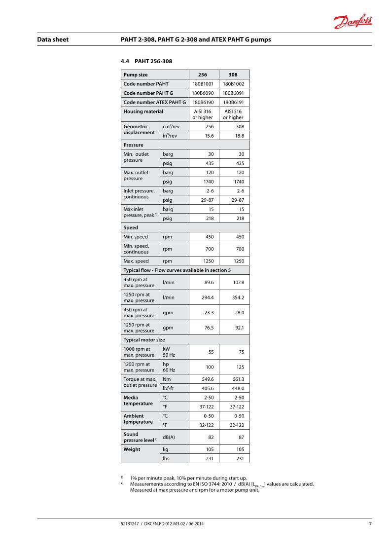
Pump size 256 308
Code number PAHT 180B1001 180B1002
Code number PAHT G 180B6090 180B6091
Code number ATEX PAHT G 180B6190 180B6191
Housing material AISI 316 or higher
AISI 316 or higher
Geometric displacement
cm³/rev 256 308
in³/rev 15.6 18.8
Pressure
Min. outlet pressure
barg 30 30
psig 435 435
Max. outlet pressure
barg 120 120
psig 1740 1740
Inlet pressure, continuous
barg 2-6 2-6
psig 29-87 29-87
Max inlet pressure, peak 1)
barg 15 15
psig 218 218
Speed
Min. speed rpm 450 450
Min. speed, continuous rpm 700 700
Max. speed rpm 1250 1250
Typical flow - Flow curves available in section 5
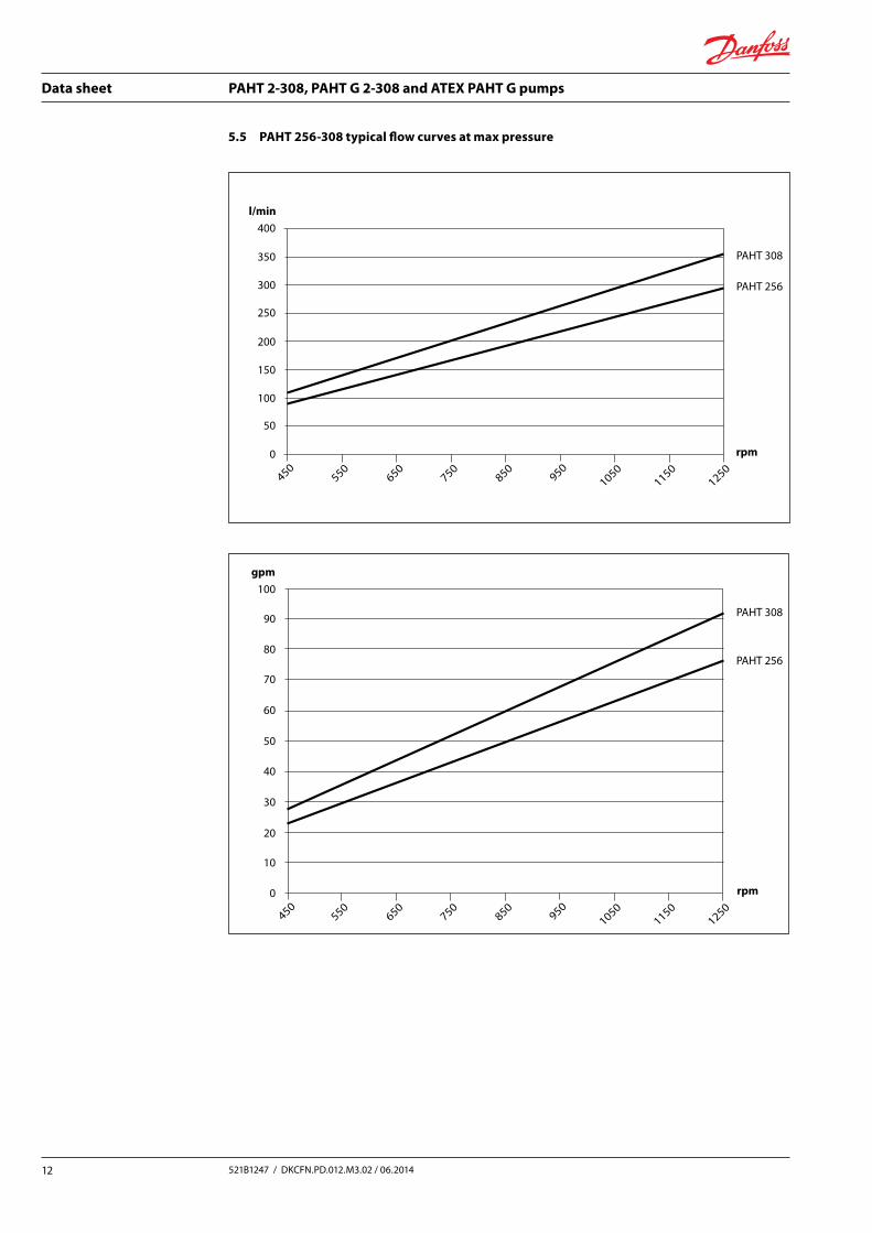
450 rpm at max. pressure l/min 89.6 107.8
1250 rpm at max. pressure l/min 294.4 354.2
450 rpm at max. pressure gpm 23.3 28.0
1250 rpm at max. pressure gpm 76.5 92.1
Typical motor size
1000 rpm at max. pressure
kW50 Hz 55 75
1200 rpm at max. pressure
hp60 Hz 100 125
Torque at max. outlet pressure
Nm 549.6 661.3
lbf-ft 405.6 448.0
Media temperature
°C 2-50 2-50
°F 37-122 37-122
Ambient temperature
°C 0-50 0-50
°F 32-122 32-122
Sound pressure level 2) dB(A) 82 87
Weight kg 105 105
lbs 231 231
4.4 PAHT 256-308
1) 1% per minute peak, 10% per minute during start up.2) Measurements according to EN ISO 3744: 2010 / dB(A) [LPA, 1m] values are calculated.
Measured at max pressure and rpm for a motor pump unit.

Data sheet PAHT 2-308, PAHT G 2-308 and ATEX PAHT G pumps
8 521B1247 / DKCFN.PD.012.M3.02 / 06.2014
5. Flow The flow (Q eff) at various pressure (pmax) can be calculated with the following equation:
Q eff = Q (th) – [(Q (th) – Q (p max)) x (p / p max)]
The theoretical flow can be calculated with the following equation:
V x nQ (th) = 1000
At zero pressure the true flow equals the theoretical flow Q (th).
Q (th): Theoretical flow (l/min / gpm)Q (pmax): Flows at max. pressure (l/min and
gpm), see 4.1-4.4p max: Max pressure (barg / psig)p: Pressure (barg / psig)V: Displacement (cm3 / rev.)n: Motor speed (rpm)
5.1 PAHT 2-6.3 typical flow curves at max pressure
20
18
16
14
12
10
8
6
4
2
0 rpm
PAHT 2.0
PAHT 3.2
PAHT 4.0
PAHT 6.3
l/min
10001250
15001750
20002500
22502750
3000
5.0
4.5
4.0
3.5
3.0
2.5
2.0
1.5
1.0
0.5
gpm
0
10001250
15001750
20002500
22502750
3000
rpm
PAHT 6.3
PAHT 4.0
PAHT 3.2
PAHT 2.0
20
18
16
14
12
10
8
6
4
2
0 rpm
PAHT 2.0
PAHT 3.2
PAHT 4.0
PAHT 6.3
l/min
10001250
15001750
20002500
22502750
3000
5.0
4.5
4.0
3.5
3.0
2.5
2.0
1.5
1.0
0.5
gpm
0
10001250
15001750
20002500
22502750
3000
rpm
PAHT 6.3
PAHT 4.0
PAHT 3.2
PAHT 2.0
Data sheet PAHT 2-308, PAHT G 2-308 and ATEX PAHT G pumps
9521B1247 / DKCFN.PD.012.M3.02 / 06.2014
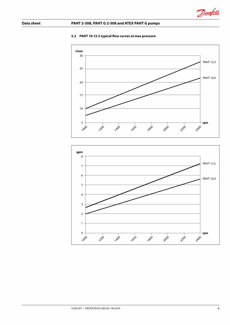
5.2 PAHT 10-12.5 typical flow curves at max pressure
30
25
20
15
10
5 rpm
PAHT 10.0
PAHT 12.5
PAHT 10.0
PAHT 12.5
l/min
gpm
10001200
14001650
18002200
20002400
rpm
10001200
14001650
18002200
20002400
8
7
6
5
4
3
2
1
0
30
25
20
15
10
5 rpm
PAHT 10.0
PAHT 12.5
PAHT 10.0
PAHT 12.5
l/min
gpm
10001200
14001650
18002200
20002400
rpm
10001200
14001650
18002200
20002400
8
7
6
5
4
3
2
1
0
Data sheet PAHT 2-308, PAHT G 2-308 and ATEX PAHT G pumps
10 521B1247 / DKCFN.PD.012.M3.02 / 06.2014
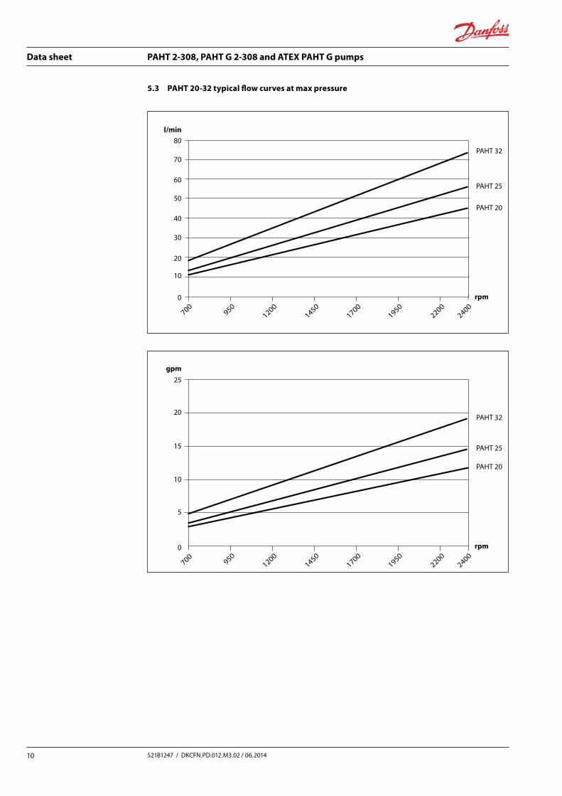
5.3 PAHT 20-32 typical flow curves at max pressure
80
70
60
50
40
30
20
10
0 rpm
PAHT 20
PAHT 25
PAHT 32
PAHT 20
PAHT 25
PAHT 32
l/min
25
20
15
10
5
gpm
700950
12001450
19501700
22002400
0 rpm
700950
12001450
19501700
22002400
80
70
60
50
40
30
20
10
0 rpm
PAHT 20
PAHT 25
PAHT 32
PAHT 20
PAHT 25
PAHT 32
l/min
25
20
15
10
5
gpm
700950
12001450
19501700
22002400
0 rpm
700950
12001450
19501700
22002400
Data sheet PAHT 2-308, PAHT G 2-308 and ATEX PAHT G pumps
11521B1247 / DKCFN.PD.012.M3.02 / 06.2014
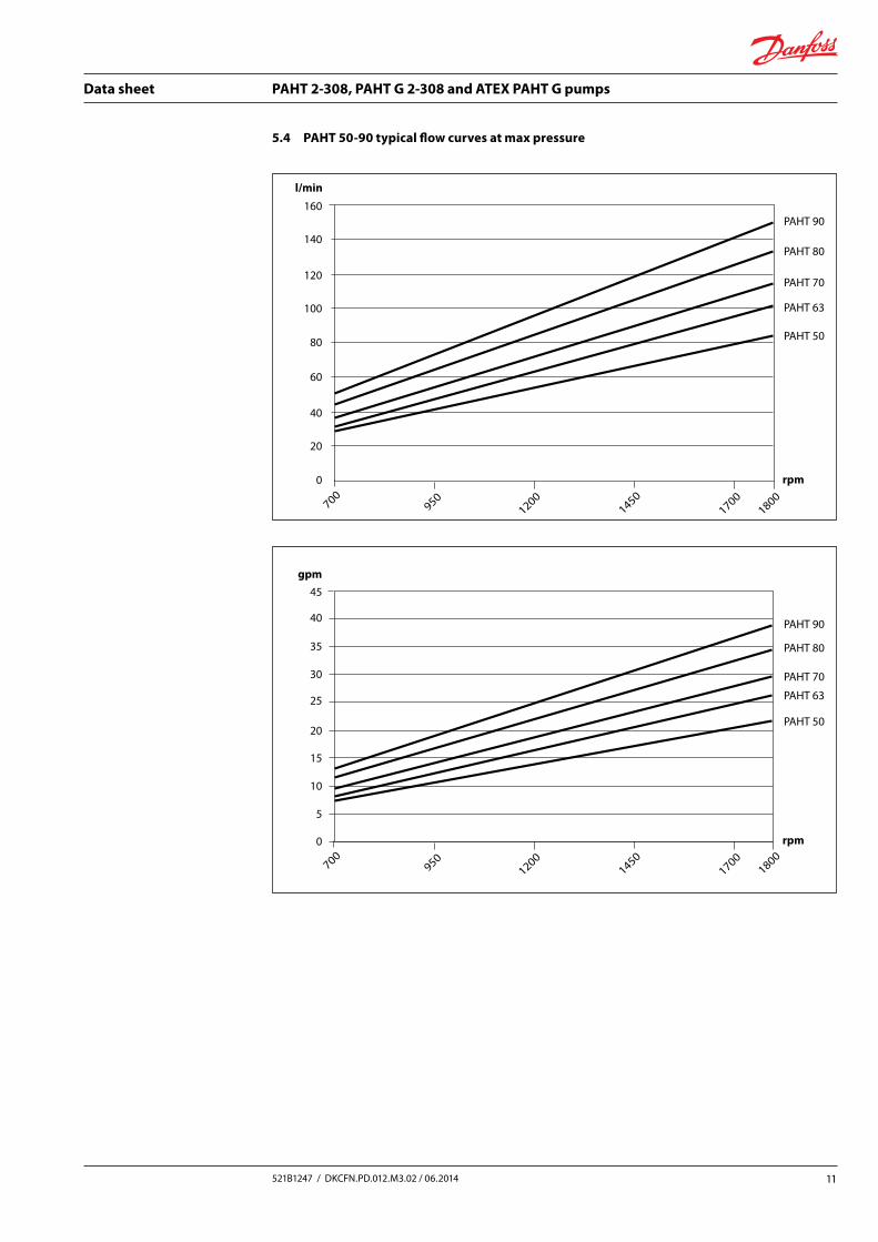
5.4 PAHT 50-90 typical flow curves at max pressure
160
140
120
100
80
60
40
20
0
0
5
10
15
20
25
30
35
40
45
l/min
gpm
1200950
14501700
1800700
rpm
PAHT 80
PAHT 50
PAHT 63
PAHT 70
PAHT 90
PAHT 80
PAHT 50
PAHT 63
PAHT 70
PAHT 90
1200950
14501700
1800700
rpm
160
140
120
100
80
60
40
20
0
0
5
10
15
20
25
30
35
40
45
l/min
gpm
1200950
14501700
1800700
rpm
PAHT 80
PAHT 50
PAHT 63
PAHT 70
PAHT 90
PAHT 80
PAHT 50
PAHT 63
PAHT 70
PAHT 90
1200950
14501700
1800700
rpm
Data sheet PAHT 2-308, PAHT G 2-308 and ATEX PAHT G pumps
12 521B1247 / DKCFN.PD.012.M3.02 / 06.2014
5.5 PAHT 256-308 typical flow curves at max pressure
400
350
300
250
200
150
100
50
0
30
20
10
0
l/min
100
90
80
70
60
50
40
gpm
550650
750850
10501150
1250950
450rpm
PAHT 256
PAHT 308
PAHT 256
PAHT 308
550650
750850
10501150
1250950
450rpm
400
350
300
250
200
150
100
50
0
30
20
10
0
l/min
100
90
80
70
60
50
40
gpm
550650
750850
10501150
1250950
450rpm
PAHT 256
PAHT 308
PAHT 256
PAHT 308
550650
750850
10501150
1250950
450rpm
Data sheet PAHT 2-308, PAHT G 2-308 and ATEX PAHT G pumps
13521B1247 / DKCFN.PD.012.M3.02 / 06.2014
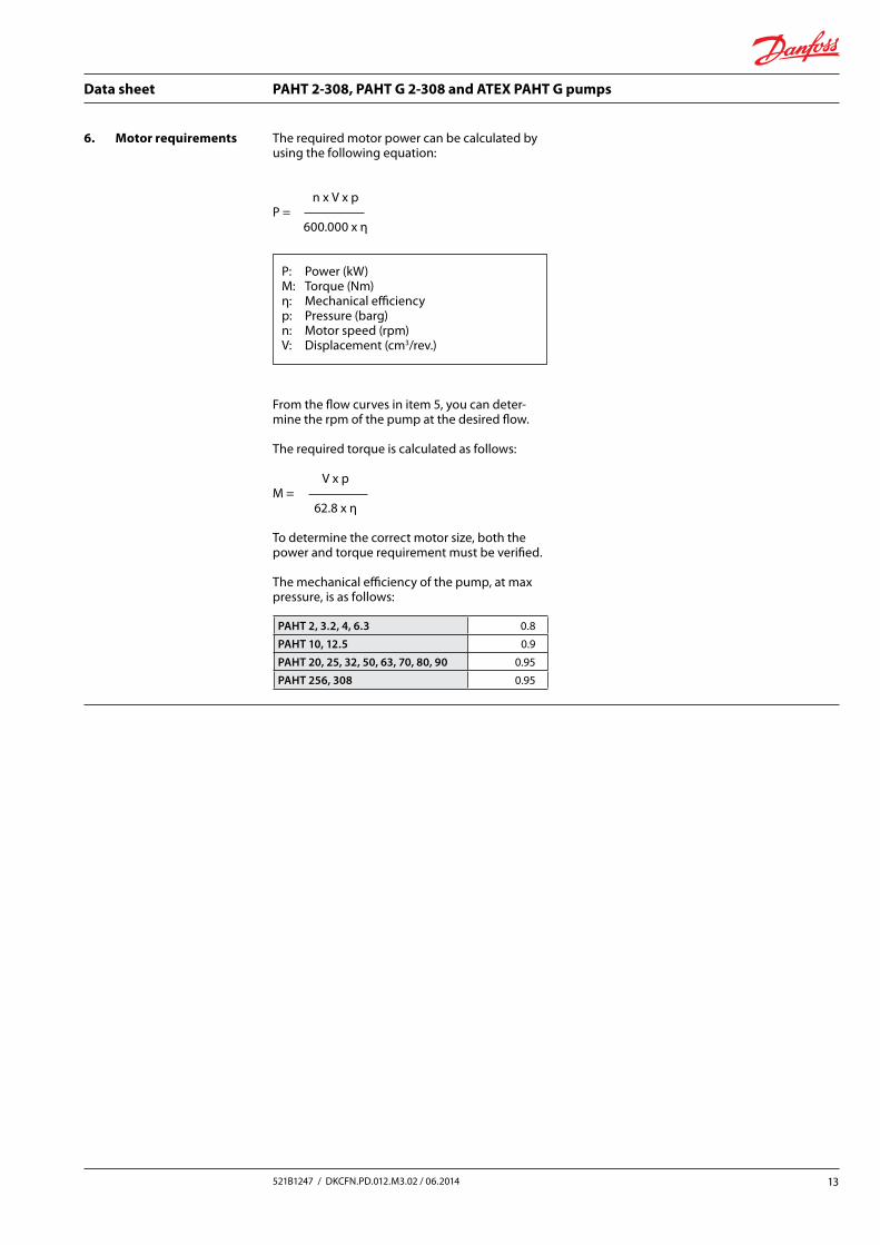
6. Motor requirements The required motor power can be calculated by using the following equation:
n x V x pP = 600.000 x η
From the flow curves in item 5, you can deter-mine the rpm of the pump at the desired flow.
The required torque is calculated as follows:
V x pM = 62.8 x η
To determine the correct motor size, both the power and torque requirement must be verified.
The mechanical efficiency of the pump, at max pressure, is as follows:
PAHT 2, 3.2, 4, 6.3 0.8
PAHT 10, 12.5 0.9
PAHT 20, 25, 32, 50, 63, 70, 80, 90 0.95
PAHT 256, 308 0.95
P: Power (kW)M: Torque (Nm)η: Mechanical efficiencyp: Pressure (barg)n: Motor speed (rpm)V: Displacement (cm3/rev.)
Data sheet PAHT 2-308, PAHT G 2-308 and ATEX PAHT G pumps
14 521B1247 / DKCFN.PD.012.M3.02 / 06.2014
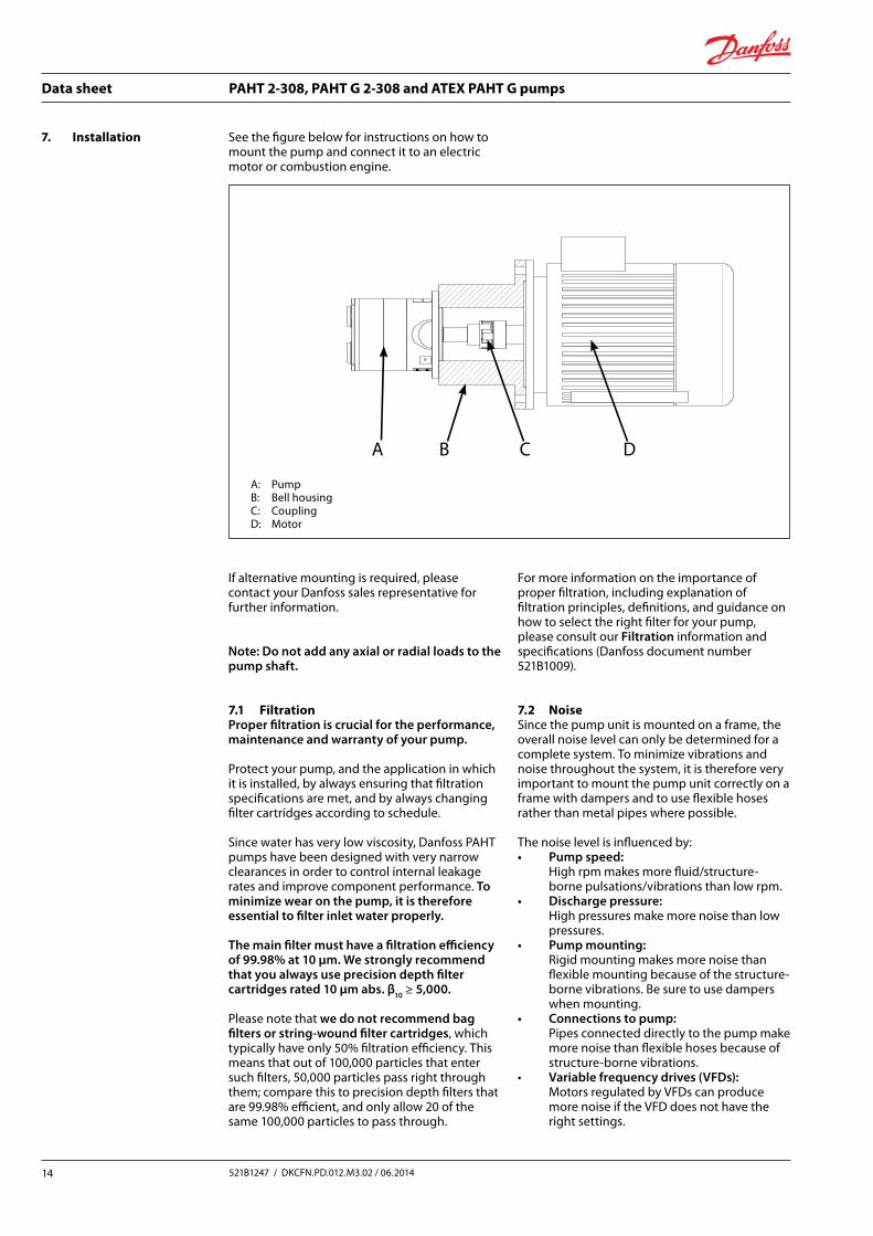
7. Installation See the figure below for instructions on how to mount the pump and connect it to an electric motor or combustion engine.
If alternative mounting is required, please contact your Danfoss sales representative for further information.
Note: Do not add any axial or radial loads to the pump shaft.
7.1 Filtration Proper filtration is crucial for the performance, maintenance and warranty of your pump.
Protect your pump, and the application in which it is installed, by always ensuring that filtration specifications are met, and by always changing filter cartridges according to schedule.
Since water has very low viscosity, Danfoss PAHT pumps have been designed with very narrow clearances in order to control internal leakage rates and improve component performance. To minimize wear on the pump, it is therefore essential to filter inlet water properly.
The main filter must have a filtration efficiency of 99.98% at 10 μm. We strongly recommend that you always use precision depth filter cartridges rated 10 μm abs. β10 ≥ 5,000.
Please note that we do not recommend bag filters or string-wound filter cartridges, which typically have only 50% filtration efficiency. This means that out of 100,000 particles that enter such filters, 50,000 particles pass right through them; compare this to precision depth filters that are 99.98% efficient, and only allow 20 of the same 100,000 particles to pass through.
For more information on the importance of proper filtration, including explanation of filtration principles, definitions, and guidance on how to select the right filter for your pump, please consult our Filtration information and specifications (Danfoss document number 521B1009).
7.2 Noise Since the pump unit is mounted on a frame, the overall noise level can only be determined for a complete system. To minimize vibrations and noise throughout the system, it is therefore very important to mount the pump unit correctly on a frame with dampers and to use flexible hoses rather than metal pipes where possible.
The noise level is influenced by: • Pump speed:
High rpm makes more fluid/structure- borne pulsations/vibrations than low rpm.
• Discharge pressure: High pressures make more noise than low pressures.
• Pump mounting: Rigid mounting makes more noise than flexible mounting because of the structure-borne vibrations. Be sure to use dampers when mounting.
• Connections to pump: Pipes connected directly to the pump make more noise than flexible hoses because of structure-borne vibrations.
• Variable frequency drives (VFDs): Motors regulated by VFDs can produce more noise if the VFD does not have the right settings.
A: PumpB: Bell housingC: CouplingD: Motor
A CB D
Data sheet PAHT 2-308, PAHT G 2-308 and ATEX PAHT G pumps
15521B1247 / DKCFN.PD.012.M3.02 / 06.2014
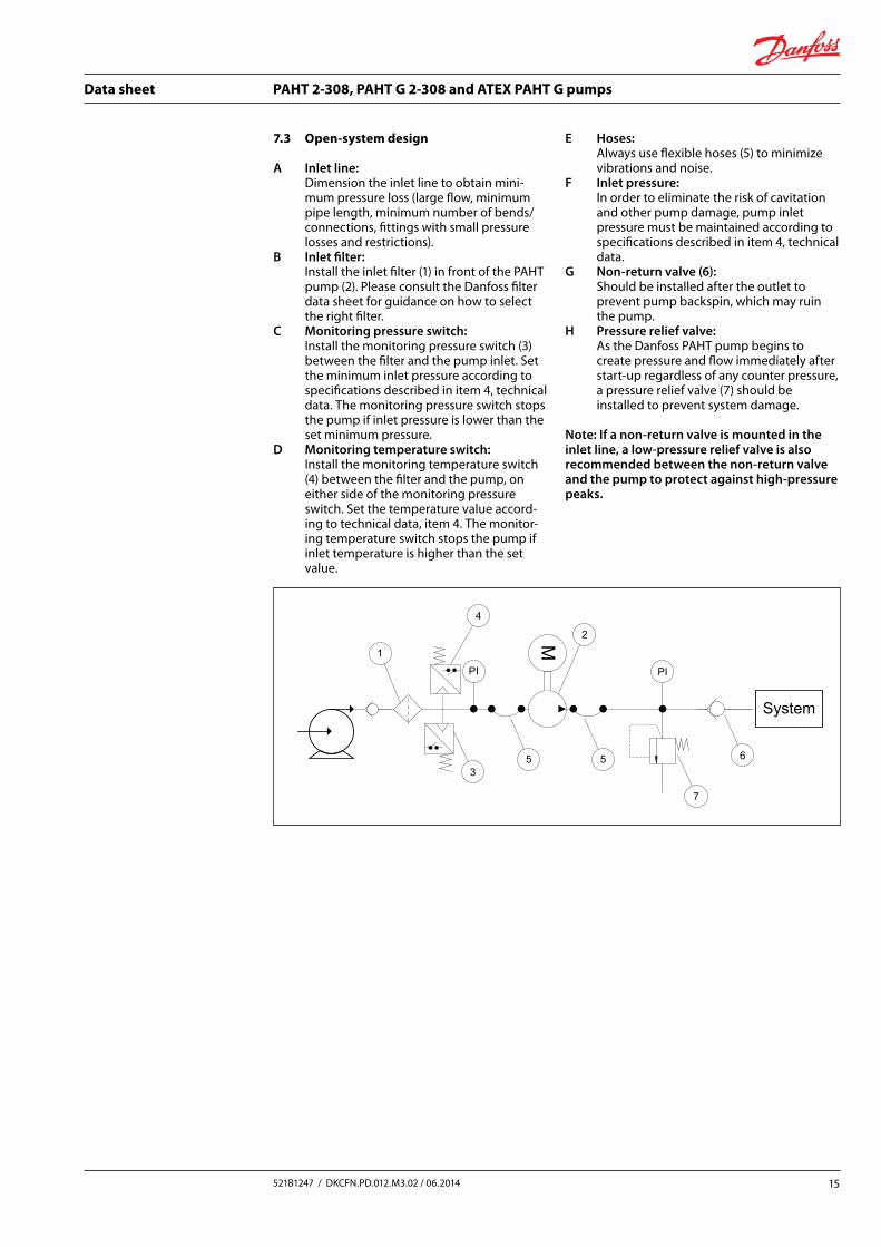
7.3 Open-system design
A Inlet line: Dimension the inlet line to obtain mini-mum pressure loss (large flow, minimum pipe length, minimum number of bends/connections, fittings with small pressure losses and restrictions).
B Inlet filter: Install the inlet filter (1) in front of the PAHT pump (2). Please consult the Danfoss filter data sheet for guidance on how to select the right filter.
C Monitoring pressure switch: Install the monitoring pressure switch (3) between the filter and the pump inlet. Set the minimum inlet pressure according to specifications described in item 4, technical data. The monitoring pressure switch stops the pump if inlet pressure is lower than the set minimum pressure.
D Monitoring temperature switch: Install the monitoring temperature switch (4) between the filter and the pump, on either side of the monitoring pressure switch. Set the temperature value accord-ing to technical data, item 4. The monitor-ing temperature switch stops the pump if inlet temperature is higher than the set value.
E Hoses: Always use flexible hoses (5) to minimize vibrations and noise.
F Inlet pressure: In order to eliminate the risk of cavitation and other pump damage, pump inlet pressure must be maintained according to specifications described in item 4, technical data.
G Non-return valve (6): Should be installed after the outlet to prevent pump backspin, which may ruin the pump.
H Pressure relief valve: As the Danfoss PAHT pump begins to create pressure and flow immediately after start-up regardless of any counter pressure, a pressure relief valve (7) should be installed to prevent system damage.
Note: If a non-return valve is mounted in the inlet line, a low-pressure relief valve is also recommended between the non-return valve and the pump to protect against high-pressure peaks.
Reservoir
PI
System
PI
MPI
System
PI
M
1
2
3
4
5 5
7
6
1
2
3
4
6 6 7
8
5
9
10
11
Data sheet PAHT 2-308, PAHT G 2-308 and ATEX PAHT G pumps
16 521B1247 / DKCFN.PD.012.M3.02 / 06.2014
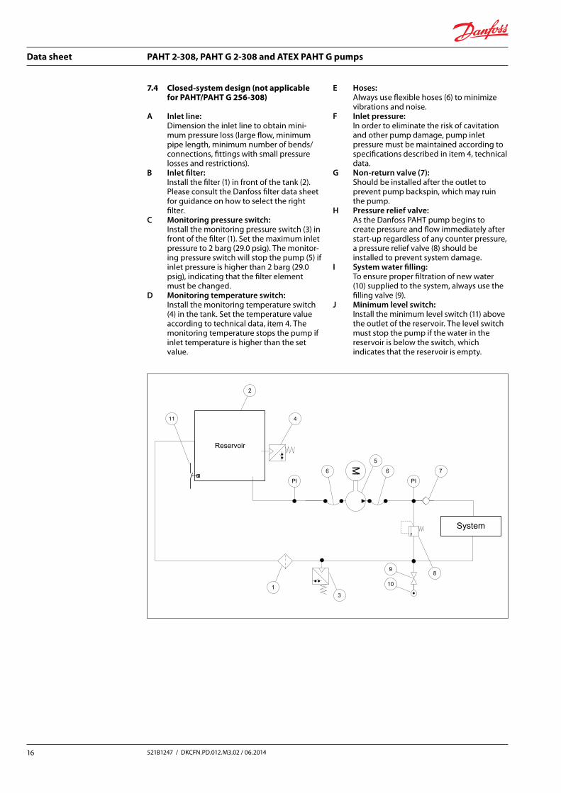
7.4 Closed-system design (not applicable for PAHT/PAHT G 256-308)
A Inlet line: Dimension the inlet line to obtain mini-mum pressure loss (large flow, minimum pipe length, minimum number of bends/connections, fittings with small pressure losses and restrictions).
B Inlet filter: Install the filter (1) in front of the tank (2). Please consult the Danfoss filter data sheet for guidance on how to select the right filter.
C Monitoring pressure switch: Install the monitoring pressure switch (3) in front of the filter (1). Set the maximum inlet pressure to 2 barg (29.0 psig). The monitor-ing pressure switch will stop the pump (5) if inlet pressure is higher than 2 barg (29.0 psig), indicating that the filter element must be changed.
D Monitoring temperature switch: Install the monitoring temperature switch (4) in the tank. Set the temperature value according to technical data, item 4. The monitoring temperature stops the pump if inlet temperature is higher than the set value.
E Hoses: Always use flexible hoses (6) to minimize vibrations and noise.
F Inlet pressure: In order to eliminate the risk of cavitation and other pump damage, pump inlet pressure must be maintained according to specifications described in item 4, technical data.
G Non-return valve (7): Should be installed after the outlet to prevent pump backspin, which may ruin the pump.
H Pressure relief valve: As the Danfoss PAHT pump begins to create pressure and flow immediately after start-up regardless of any counter pressure, a pressure relief valve (8) should be installed to prevent system damage.
I System water filling: To ensure proper filtration of new water (10) supplied to the system, always use the filling valve (9).
J Minimum level switch: Install the minimum level switch (11) above
the outlet of the reservoir. The level switch must stop the pump if the water in the reservoir is below the switch, which indicates that the reservoir is empty.
Reservoir
PI
System
PI
M
PI
System
PI
M
1
2
3
4
5 5
7
6
1
2
3
4
6 6 7
8
5
9
10
11
Data sheet PAHT 2-308, PAHT G 2-308 and ATEX PAHT G pumps
17521B1247 / DKCFN.PD.012.M3.02 / 06.2014
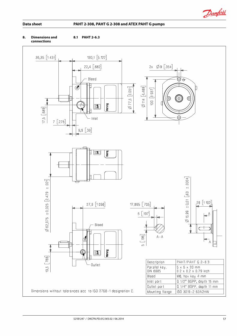
8. Dimensions and connections
8.1 PAHT 2-6.3
Data sheet PAHT 2-308, PAHT G 2-308 and ATEX PAHT G pumps
18 521B1247 / DKCFN.PD.012.M3.02 / 06.2014
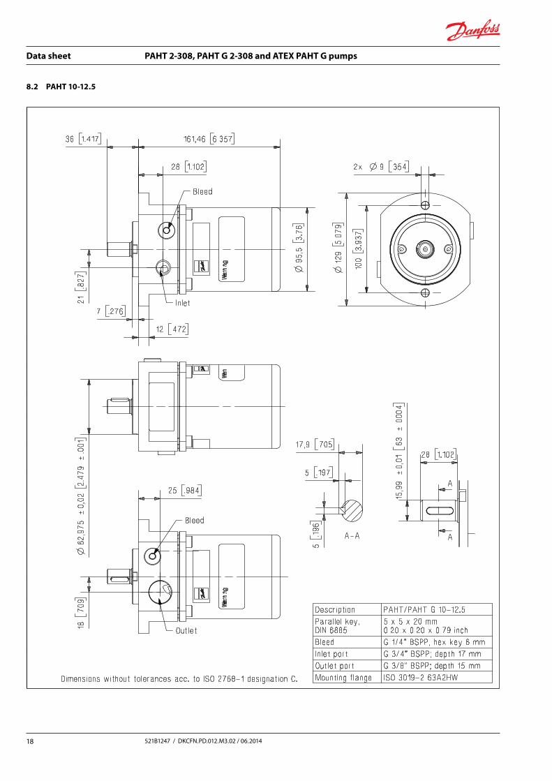
8.2 PAHT 10-12.5
Data sheet PAHT 2-308, PAHT G 2-308 and ATEX PAHT G pumps
19521B1247 / DKCFN.PD.012.M3.02 / 06.2014
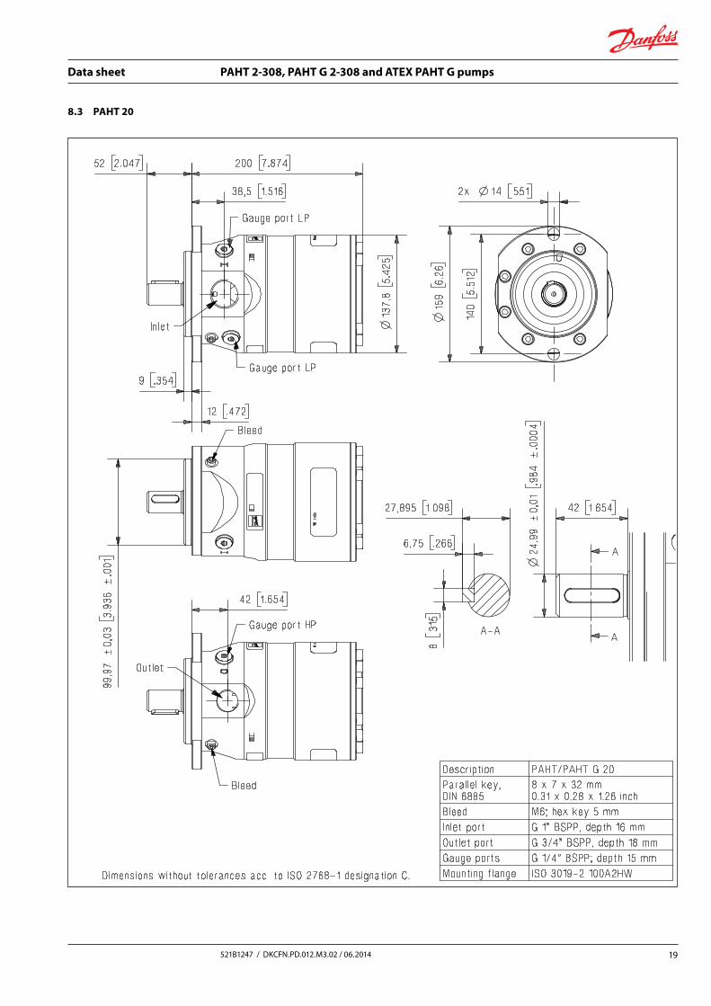
8.3 PAHT 20
Data sheet PAHT 2-308, PAHT G 2-308 and ATEX PAHT G pumps
20 521B1247 / DKCFN.PD.012.M3.02 / 06.2014
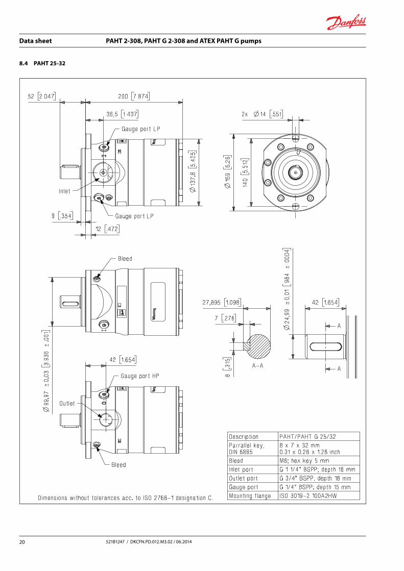
8.4 PAHT 25-32
Data sheet PAHT 2-308, PAHT G 2-308 and ATEX PAHT G pumps
21521B1247 / DKCFN.PD.012.M3.02 / 06.2014
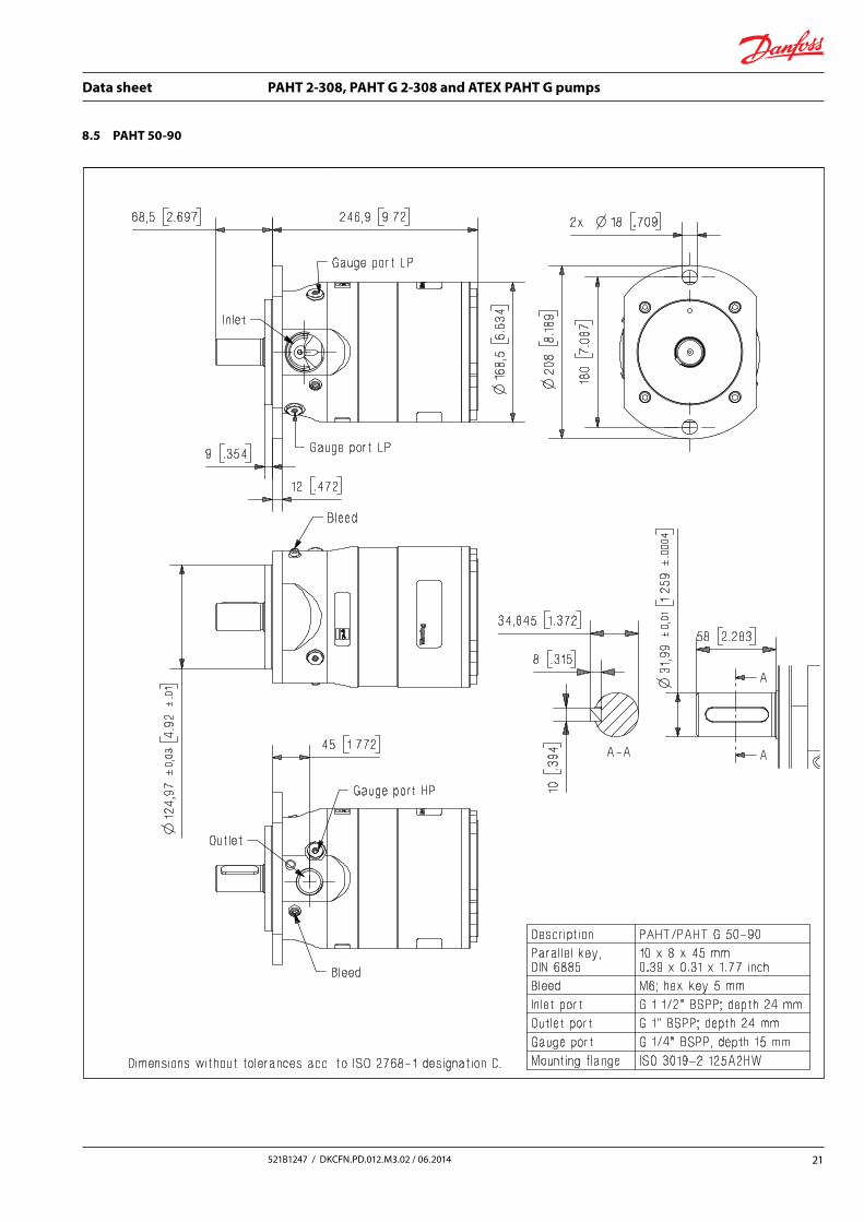
8.5 PAHT 50-90
Data sheet PAHT 2-308, PAHT G 2-308 and ATEX PAHT G pumps
22 521B1247 / DKCFN.PD.012.M3.02 / 06.2014
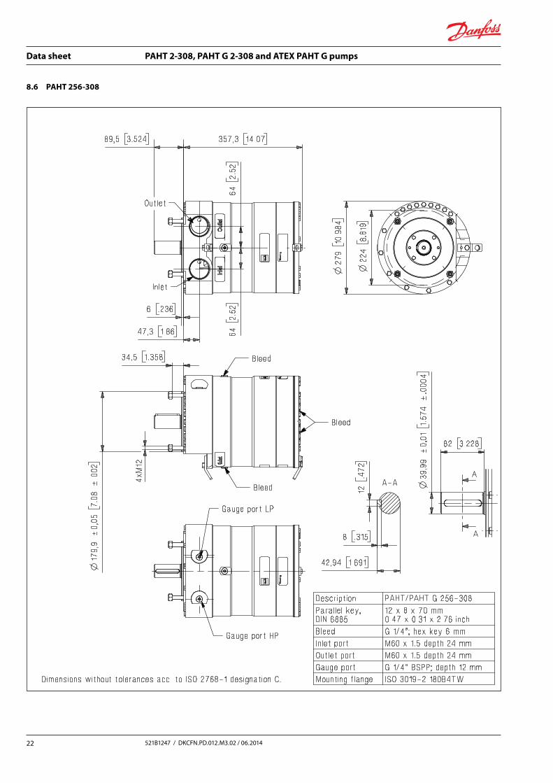
8.6 PAHT 256-308

Data sheet PAHT 2-308, PAHT G 2-308 and ATEX PAHT G pumps
23521B1247 / DKCFN.PD.012.M3.02 / 06.2014
9. Service Danfoss PAHT pumps are designed for long periods of service-free operation to ensure low maintenance and life cycle costs. Provided that the pump is installed and operated according to Danfoss specifications, Danfoss PAHT pumps typically run 8,000 hours between service. However, the service schedule for your Danfoss PAHT pump may vary according to the applica-tion and other factors.
The life of a pump may be greatly shortened if Danfoss recommendations concerning system design and operation are not followed.
In our experience, poor filtration is the number one cause of pump damage.
Other factors that affect pump performance and lifetime include:
• running the pump at speeds outside specifications
• supplying the pump with water at temper-atures higher than recommended
• running the pump at inlet pressures outside specifications
• running the pump at outlet pressures outside the specifications.
We recommend that you inspect your pump after 8,000 hours of operation even if it is running without any noticeable problems. Replace any worn parts if necessary, including pistons and shaft seals, to keep your pump running efficiently and to prevent breakdown. If worn parts are not replaced, then our guidelines recommend more frequent inspection.
Data sheet PAHT 2-308, PAHT G 2-308 and ATEX PAHT G pumps
24 521B1247 / DKCFN.PD.012.M3.02 / 06.2014
Danfoss can accept no responsibility for possible errors in catalogues, brochures and other printed material. Danfoss reserves the right to alter its products without notice. This also applies to products already on order provided that such alterations can be made without subsequential changes being necessary in specifications already agreed.All trademarks in this material are property of the respective companies. Danfoss and the Danfoss logotype are trademarks of Danfoss A/S. All rights reserved.
Danfoss A/SHigh Pressure PumpsDK-6430 NordborgDenmark
[email protected] Tel. +31-152-610-900www.lenntech.com Fax. +31-152-616-289