Extra-Solar Planets Planetary Physics Summer Term 2004 Lecture 10.

Astrometric Survey for Extra-Solar Planetswith PRIMA
Requirements on Medium-Term Stability of Air Parameters inVLTI Ducts and Delay Lines
Doc. No. VLT-SPE-AOS-15753-0003Issue 0.2.172Date June 21, 2006
Prepared Richard J. Mathar June 21, 2006Signature
Approved Denis Megevand June 21, 2006Signature
Released Didier Queloz June 21, 2006Signature

ii PRIMA: Requirements Air Parameters Issue 0.2.172 VLT-SPE-AOS-15753-0003
This page was intentionally left almost blank

PRIMA: Requirements Air Parameters Issue 0.2.172 VLT-SPE-AOS-15753-0003 iii
Change Record
Issue Date Section/Parag. affected Reason/Initiation/Documents/Remarks
0.1 07-Jul-2005 all created0.1.194 13-Jul-2005 Section 5.2 added0.1.195 14-Jul-2005 Section 6, Ref [5] added0.1.206 25-Jul-2005 Section 7.2 added0.1.291 18-Oct-2005 all updated references to current [10, 14]0.1.321 17-Nov-2005 Ref. [9] changed document number0.2.172 21-Jun-2006 all updated references to current [10, 11, 14]

iv PRIMA: Requirements Air Parameters Issue 0.2.172 VLT-SPE-AOS-15753-0003
This page was intentionally left almost blank

PRIMA: Requirements Air Parameters Issue 0.2.172 VLT-SPE-AOS-15753-0003 1
1 Abstract
Astrometry with PRIMA/VLTI puts high requirements on the knowledge of 4-way, dual-beam differ-ential optical path differences for off-axis beams impinging on two Auxiliary Telescopes. The DRS
needs accurate estimates of the refractive index of the air in the ducts, main delay line tunnel and in-terferometric laboratory to convert phase measurements to “vacuum” delays attributed to the beamsabove the atmosphere. The dependence of the refractive index on wavenumber and air compositionleads to requirements on the knowledge and/or control of temperature, pressure and humidity.
In fulfillment of the PDR AI #2 [2], the requirements are summarized here. This document is notcovered by the SOW [1].
1.1 Documents
[1] Delplancke, F. 2004, SoW for PRIMA Astrometric Operations and Software. VLT-SOW-ESO-15750-3298
[2] — 2005, Minutes of Meeting, PAOS Preliminary Design Review. TSD-05/42
[3] — 2005, PRIMA Astrometric Instrument, Template Reference Guide. VLT-TRE-ESO-15750-3669
[4] — 2005, Prima Differential Delay Line (DDL), Performance & Technical Requirement Specifi-cations. VLT-SPE-ESO-15720-2209
[5] Delplancke, F., Leveque, S., Kervella, P., Glindemann, A., & d’Arcio, L. 2000, in Interferometryin Optical Astronomy, edited by P. J. Lena, & A. Quirrenbach (Int. Soc. Optical Engineering),vol. 4006 of Proc. SPIE, 365
[6] Folco, E. D., & Koehler, B. 2002, VLTI Commissioning Part I: OPD stability, Test Report.VLT-TRE-ESO-15000-2902
[7] Glindemann, A. 2000, PRIMA, the Phase Referenced Imaging and Microarcsecond Astrometryfacility: System Description. VLT-SPE-ESO-15700-2207
[8] Leveque, S. 2000, Results of environmental tests for the VLTI at Paranal, May 11–21/00. VLT-TRE-ESO-15000-2259
[9] Mathar, R. J. 2005, Astrometric Survey for Extra-Solar Planets with PRIMA, Requirements onDifferential AT Mirror Surface Localizations. VLT-TRE-AOS-15753-0004
[10] — 2006, Astrometric Survey for Extra-Solar Planets with PRIMA, Astrometric dispersion cor-rection. UL-TRE-AOS-15753-0010
[11] — 2006, Astrometric Survey for Extra-Solar Planets with PRIMA, Choice of Detector SpectralBand Widths. UL-TRE-AOS-15753-0012
[12] Peron, M., Wallander, A., Wallace, P., Richichi, A., Ballester, P., Kaufer, A., Percheron, I.,Wittkowski, M., Hanuschik, R., Chavan, A. M., & Laing, R. 2005, Astrometric Survey forExtra-Solar Planets with PRIMA, AOS PDR RIX. VLT-SPE-AOS-15750-

2 PRIMA: Requirements Air Parameters Issue 0.2.172 VLT-SPE-AOS-15753-0003
[13] Reffert, S., Quirrenbach, A., Jaffe, W. J., & Mathar, R. J. 2005, Astrometric Survey for Extra-Solar Planets with PRIMA, Operation and Calibration Strategy. VLT-TRE-AOS-15754-0001
[14] Tubbs, R. N., & Mathar, R. J. 2006, Astrometric Survey for Extra-Solar Planets with PRIMA,Astrometric Error Budget. VLT-TRE-AOS-15753-0001
1.2 Acronyms
AI Action Item
ARC Ecole d’ingenieurs de l’arc Jurassie http://www.eiaj.ch/
ASTRON Stichting Astronomisch Onderzoek in Nederland http://www.astron.nl
AT Auxiliary Telescope (of the VLTI)http://www.eso.org/projects/vlti/AT/index at.html
DDL Differential Delay Line http://www.mpia-hd.mpg.de/PRIMA-DDL/
DOPD differential OPD
DRS Data Reduction System
EPFL Ecole Polytechnique Federale de Lausanne http://www.epfl.ch
ESO European Southern Observatory http://www.eso.org
FSU Fringe Sensing Unit
MDL main delay line
MPIA Max-Planck Institut fur Astronomie, Heidelberg http://www.mpia.de
NOVA Nederlandse Onderzoekschool voor Astronomiehttp://www.strw.leidenuniv.nl/nova/
OPD optical path difference
OPL optical path length
PDR Preliminary Design Review
PRIMA Phase-Reference Imaging and Microarcsecond Astrometryhttp://obswww.unige.ch/Instruments/PRIMA
PRIMET PRIMA Metrologyhttp://www.eso.org/projects/vlti/instru/prima/description lms prima.html
PS primary star
SOW Statement of Work
SS secondary star
UT Unit Telescope (of the VLTI) http://www.eso.org/projects/vlt/unit-tel/
VLTI Very Large Telescope Interferometer http://www.eso.org/vlti

PRIMA: Requirements Air Parameters Issue 0.2.172 VLT-SPE-AOS-15753-0003 3
2 PRIMA Astrometric Mode
The dual-beam interferometer PRIMA at the VLTI aims at µas accuracy for the differential OPD(DOPD) between the two stars/sources. Standard trigonometry for template baselines of ≈ 100 mtranslates this to requirements on the accuracy of the delay difference between the two interferometersrepresented by both beams of typically ≈ 5 nm [7]. 1
The key parameter is the DOPD
∆D = LP1 − LP2 − (LS1 − LS2) (1)
between star beams P and S from telescopes 1 and 2 to the detectors. It consists of
1. the DOPD within the atmosphere from lensing,2
2. concealed contributions from asymmetries within the two AT Coude trains,3
3. the explicit DOPD introduced by the DDL [4], optionally operating in vacuum,4
4. the implicit DOPD added by the four (different) refractive indices that convert geometric tooptical path differences in Equation (1).
This memorandum deals exclusively with the last item in this list and its role in putting requirementson environmental parameters of the VLTI tunnel.
3 Astrometric Error Budget
In rough terms, PRIMA interferometry senses phases of the two wave packets by the FSUs near their“white light” fringe position, representing the sum of the four paths L itemized in Section 2 thatcontribute to LP1 − LP2 on one FSU and LS1 − LS2 on the other. Each FSU measures a wrappedphase5
ϕ(k = K) = n(k)kDt − kD (2)
depending on
• the optical path difference nDt = L1 − L2 in the tunnel,
• the “effective” wavenumber k of the starlight,
• and the “external” D above the atmosphere,
where n(k = K) is the K-band refractive index. The DRS—in a differential way—takes these phases,reduces the PRIMET J-band DOPD to measured delay line positions Dt, then combines both to produceD.6
Here, we only look at the contribution of the variable n to the error budget, where n depends on1This transformation is detailed in Section 28.3.2 of [14], and not reviewed here.2see Section 5.4 of [10].3Section 11.4.2 of [14] and [9]4see Table 6 of [10]5In terms of radically simplified master equations of Section 6.4 of [10]6 Principles of this have been presented in Sections 4.1 and 4.2 of [11]. Use of PRIMET replaces n(k = K) − 1 in
Equation (2), which is ≈ 2 · 10−4, effectively by a term ∝ [n(k = K)− n(k = J)] which is ≈ −5 · 10−7. This has beendetailed in Section 9 of [14].

4 PRIMA: Requirements Air Parameters Issue 0.2.172 VLT-SPE-AOS-15753-0003
1. wavenumber k = 2πσ = 2π/λ (band, color)
2. molecular composition of the air, which is a function of
(a) temperature T
(b) pressure p
(c) humidity h
which all fluctuate as a function of time t and tunnel location x.
The actual fluctuations of these parameters have been characterized in Section 6.1 of [10] and inthe documentation listed in Section 23 of [14]; we explicitly do not attempt to review the actualenvironmental conditions. To the degree that the consortium has become aware of and actually gothold on documentation, and probably beyond, this information is already in the hands of ESO.
4 Dispersion Effects
4.1 Dispersion Correction
The task of the “dispersion correction” is to keep track of n to reduce the error of the knowledgeon the differential nDt below 5 nm. The dependence of air dispersion on the parameters listed inSection 3 leads to various higher-order differential terms with the potential to introduce errors.7
4.1.1 Difference in Beam Dispersion Curves
Virtual rearrangement of Equation (1) as ∆D = LP1−LS1− (LP2−LS2) shows that the “horizontal”gradients across 24 cm of beam separation remain the dominant contribution of tunnel dispersionto the error budget. Depending on how the beams are organized in the ducts, ie, whether the AT
stations are on the same or opposite side of the tunnel, the bias within LP1 − LS1 may have thesame or the opposite sign of the bias in LP2 − LS2 [8], which causes the problem to be enhanced∝ (L1 + L2), or reduced ∝ |L1 − L2|.
Pairs of consecutive measurements with swapped beams8 allow to cancel this term computationallyduring the data reduction by working with the mean of the differential phase, which eliminates theeffect to the first-order differentials ∂n/∂T , ∂n/∂h and ∂n/∂p. Considering the second order partialderivatives leads to the requirements of Section 5.1. The actual time interval between a pair ofbeam-switched measurements is left as a parameter in the calculation. This time increases if the twoconfigurations are kept apart on the template level [3].
4.1.2 Difference in Mean Star Color
Differences in the effective wavelengths of the two stars introduces two aspects when it comes toreading the two refractive indices off the dispersion curve: Knowledge of the abscissae (ie, the effectivewavenumbers), and knowledge of the refractive index at that abscissa. Only the latter belongs in
7 see Section 9 of [14] and Section 3.2.2 of [10].8Section 6.1 of the PDR documentation [13]

PRIMA: Requirements Air Parameters Issue 0.2.172 VLT-SPE-AOS-15753-0003 5
here.9 The requirements in Section 5.2 follow in straight forward manner by reverse reading of thesecond table on page 55 of [14].
4.2 Pistonic Fluctuations
Short term “statistical” contributions from density fluctuations [6] within the detector integrationtime introduce k-dependent Strehl factors (loss of coherence) that modify the effective shape of theK-band spectrum equivalent to a reddening, see Figure 1.10
0.99994
0.99995
0.99996
0.99997
0.99998
0.99999
1
2 2.05 2.1 2.15 2.2 2.25 2.3 2.35 2.4 2.45
Stre
hl
wavelength / µm
s050hz029s050hz029
s050hz33
s050hz34
Figure 1: Strehl factor exp(−σ2ϕ/2) for four measured OPL fluctuations caused by the UT3 duct [8],
assuming a t = 48 ms integration time. σϕ = 2πσL/λ and σL ∝ t3/4.
Although the high-frequency reading of PRIMET provides the information to estimate the effect,the high resolution of 11 000 requested for the effective wavenumber11 might call for frequent re-calibration of the effective K-band spectrum due to changes in the turbulence spectrum of the tunnel.
The signature of this tunnel seeing effect is separable from the atmospheric seeing effect, since itcreates a residual pistonic motion of the SS even with perfect tracking of the PS, and limits theintegration time also for the SS to increase the effect of readout and photon noise.
This establishes the requirements of Section 5.3.9The star color term listed under the second bullet of item 2 of Section 2 of [14] is off topic in this subsection because
it is not correlated to fluctuations of the ambient parameters. However, it resurfaces to produce the systematic effectof Section 4.2.
10 and Section 23.4 of [14]. The same effect is produced by mirror vibrations which show the same chromaticity inthe phase and have been measured at 100 nm in the tunnel and 100 nm in one AT arm [12, RIX 003]—which, again,is off-topic here, but means more of these error terms bite off a piece of the same cake.
11 Equation (34) and Table 1 of [14]. This assumes the layout of the FSU spectral channels as planned.

6 PRIMA: Requirements Air Parameters Issue 0.2.172 VLT-SPE-AOS-15753-0003
5 Requirements
5.1 Horizontal Inter-Beam Temperature/Humidity Gradient Drift
The horizontal temperature gradient must change on longer time-scales than needed for the beamswapping. The residual error that would not be removed by the beam swapping technique is propor-tional to the second derivative of ∂2n/∂T 2 multiplied by the half of the product of the inter-beamtemperature difference, of the temperature drift during the swap, and of L1+L2 (using the pessimisticsign of Section 4.1). More generally, the sum of the contribution of all second order derivatives withrespect to the parameters of n must stay below 5 nm. Table 1 shows
• in the first column the pair of variables that could differ between the beams and/or change intime,
• in the second column and third column the typical values of the second derivative and its units,
• and in the last column the allowance in the spatio-temporal product of inter-beam bias and timedrift between swaps to keep the error below 5 nm, assuming a typical value of (L1+L2)/2 ≈ 180m.12
2nd derivative units product requirement∂2n/∂T 2 −1.2 · 10−9 1/K2 0.023∂2n/∂h2 −3.3 · 10−7 1/(mole/m3)2 0.000082∂2n/∂p2 −2. · 10−14 1/Pa2 1400.
∂2n/(∂T∂h) 6.6 · 10−7 1/(K mole/m3) 0.000042∂2n/(∂T∂p) −1.4 · 10−10 1/(K Pa) 0.20∂2n/(∂h∂p) 1.4 · 10−10 1/(mole/m3 Pa) 0.20
Table 1: Second derivatives of the index of refraction w.r.t. temperature, absolute humidity and airpressure at a wavelength of 2.25 µm, typical values inside the VLTI tunnel.
The way of reading the first line in the table is, for example, that a temperature difference of 0.1 Kbetween the beams can lead to an error of 5 nm if both temperatures drift by 0.23 K during the beamswap, or that a temperature difference of 0.2 K to the same error of 5 nm if both drift by 0.11 Kduring the swap. The interpretation of the fourth line is, for example, that a temperature differenceof 0.1 K allows a drift of absolute humidity of 0.00042 mole/m3 or that a humidity difference of0.1 mole/m3 allows a temperature drift of 0.00042 K (the second interpretation being unrealistic, ofcourse). The sensitivity to the ambient pressure fluctuations is weak.
5.2 Mean Molecular Composition I
The error in the contribution D∆λ∂n∂k to the DOPD for known effective wavenumber difference ∆k of
the two stars consists of contributions from temperature fluctuations ∆T and humidity fluctuations∆h according to
D∆n = D∆σ∂n
∂σ+ D∆σ
(∂2n
∂σ∂T∆T +
∂2n
∂σ∂h∆h +
∂2n
∂σ∂p∆p
), (3)
12taken from Figure 11 of [10]

PRIMA: Requirements Air Parameters Issue 0.2.172 VLT-SPE-AOS-15753-0003 7
where σ = 1/λ with coefficients listed in Table 2.13
2nd derivative units product requirement∂2n/(∂σ∂T ) −3.5 · 10−13 1/(cm−1 K) 140.∂2n/(∂σ∂h) 1.25 · 10−10 1/(cm−1 mole/m3) 0.40∂2n/(∂σ∂p) 1.3 · 10−15 1/(cm−1 Pa) 37000.
Table 2: Second derivatives of the index of refraction w.r.t. spectroscopic wavenumber, temperature,absolute humidity and air pressure at a wavelength of 2.25 µm.
The second term at the r.h.s. of Equation (3) is to be kept smaller than 5 nm at a typical delayof D = 100 m, which yields the requirements on the products ∆σ∆T , ∆σ∆h and ∆σ∆p which areincluded in the last column of the table. For a total error below 5 nm, the values ought be dividedby two—the variation in the pressure is negligible and the error may be shared by the contributionfrom ∆T and ∆h. The transition from different star temperatures to ∆σ is shown with Figure 23 of[11].
Example: For the central spectral channel, ∆σ will hardly ever be larger than 10 cm−1 or ∆k/k =1/440; from the last column in Table 2 one deduces that a combined knowledge of the temperatureto 7◦C and absolute humidity to 0.02 mole/m3 suffices to keep the total error below 5 nm.14 Theeffective wavenumber of spectral channel in the short-K band, however, is much more sensitive to thestar color,15 rendering a wavenumber difference of 10 cm−1 quite plausible; an independent DOPD
estimate from this spectral channel puts more stress on the sensor network.
5.3 Turbulence
To enforce that the decoherencing described in Section 4.2 does not change the effective wavenumberby more than 0.4 cm−1 in the central spectral window on behalf of the star color term,16 the varianceσL of the differential OPD over the detector integration time interval17 at the specific star temperaturemust stay below 66 nm.18 This effect of turbulence in the ducts implicitly limits the integration timefor blind tracking on the SS, for example to 880 ms and 1.1 s for the two measurements s050hz029in Table 10 of [8], or to about 300 ms for the more turbulent environment measured under p050hz10in Table 16 of [8].
The transition from turbulent to laminar flow in the ducts could be made by reducing the air velocitybelow (estimated) 0.1 m/s.19 This would leave only larger convection rolls in the MDL tunnel causedby the vertical temperature gradients, which probably would live on outer scales larger than theinter-beam distance of 24 cm.20
13At 2.25 µm, ∂n/∂σ ≈ 1.1 · 10−10 1/cm−1, which can be read from Figures 3, 6 of [10] or 15 of [11]. ∂2n/(∂σ∂T ) ≈−(∂n/∂σ)/T at T ≈ 300 K as expected from the ideal gas equation.
14The humidity bound is usually more difficult to meet than the temperature bounds, and a trade-off can be made.15Bottom of Figure 23 of [11].16listed under the second bullet of item 2 of Section 2 of [14] to keep the error below 5 nm at 100 m OPD. To be
devided by√
2 to account for both stars.17See Figure 2 of [5]18Simulated for black body spectra from 3000 to 12000 K multiplied by the detector quantum efficiency and the
Strehl factors as in Figure 1.19see Section B.3 of [14].20This would explain why the DOPD fluctuations in the tunnel have been measured to be much smaller than in the
ducts [8]. It also predicts that the conditions in the narrower AT ducts are more turbulent than in the UT ducts.
8 PRIMA: Requirements Air Parameters Issue 0.2.172 VLT-SPE-AOS-15753-0003
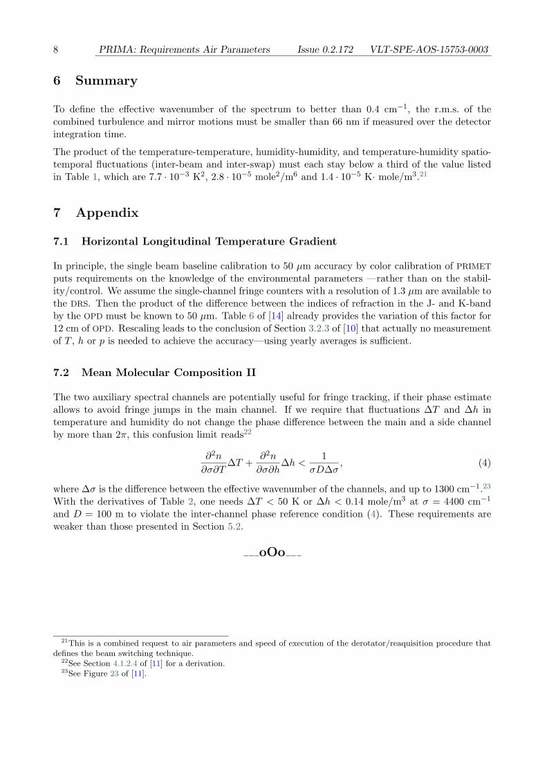
6 Summary
To define the effective wavenumber of the spectrum to better than 0.4 cm−1, the r.m.s. of thecombined turbulence and mirror motions must be smaller than 66 nm if measured over the detectorintegration time.
The product of the temperature-temperature, humidity-humidity, and temperature-humidity spatio-temporal fluctuations (inter-beam and inter-swap) must each stay below a third of the value listedin Table 1, which are 7.7 · 10−3 K2, 2.8 · 10−5 mole2/m6 and 1.4 · 10−5 K· mole/m3.21
7 Appendix
7.1 Horizontal Longitudinal Temperature Gradient
In principle, the single beam baseline calibration to 50 µm accuracy by color calibration of PRIMET
puts requirements on the knowledge of the environmental parameters —rather than on the stabil-ity/control. We assume the single-channel fringe counters with a resolution of 1.3 µm are available tothe DRS. Then the product of the difference between the indices of refraction in the J- and K-bandby the OPD must be known to 50 µm. Table 6 of [14] already provides the variation of this factor for12 cm of OPD. Rescaling leads to the conclusion of Section 3.2.3 of [10] that actually no measurementof T , h or p is needed to achieve the accuracy—using yearly averages is sufficient.
7.2 Mean Molecular Composition II
The two auxiliary spectral channels are potentially useful for fringe tracking, if their phase estimateallows to avoid fringe jumps in the main channel. If we require that fluctuations ∆T and ∆h intemperature and humidity do not change the phase difference between the main and a side channelby more than 2π, this confusion limit reads22
∂2n
∂σ∂T∆T +
∂2n
∂σ∂h∆h <
1σD∆σ
, (4)
where ∆σ is the difference between the effective wavenumber of the channels, and up to 1300 cm−1.23
With the derivatives of Table 2, one needs ∆T < 50 K or ∆h < 0.14 mole/m3 at σ = 4400 cm−1
and D = 100 m to violate the inter-channel phase reference condition (4). These requirements areweaker than those presented in Section 5.2.
oOo
21This is a combined request to air parameters and speed of execution of the derotator/reaquisition procedure thatdefines the beam switching technique.
22See Section 4.1.2.4 of [11] for a derivation.23See Figure 23 of [11].